EP3704367B1 - Transmission assembly for an engine - Google Patents
Transmission assembly for an engine Download PDFInfo
- Publication number
- EP3704367B1 EP3704367B1 EP18743979.9A EP18743979A EP3704367B1 EP 3704367 B1 EP3704367 B1 EP 3704367B1 EP 18743979 A EP18743979 A EP 18743979A EP 3704367 B1 EP3704367 B1 EP 3704367B1
- Authority
- EP
- European Patent Office
- Prior art keywords
- controlling member
- connecting rod
- support element
- pair
- engine
- Prior art date
- Legal status (The legal status is an assumption and is not a legal conclusion. Google has not performed a legal analysis and makes no representation as to the accuracy of the status listed.)
- Active
Links
Images




Classifications
-
- F—MECHANICAL ENGINEERING; LIGHTING; HEATING; WEAPONS; BLASTING
- F01—MACHINES OR ENGINES IN GENERAL; ENGINE PLANTS IN GENERAL; STEAM ENGINES
- F01B—MACHINES OR ENGINES, IN GENERAL OR OF POSITIVE-DISPLACEMENT TYPE, e.g. STEAM ENGINES
- F01B9/00—Reciprocating-piston machines or engines characterised by connections between pistons and main shafts, not specific to groups F01B1/00 - F01B7/00
- F01B9/02—Reciprocating-piston machines or engines characterised by connections between pistons and main shafts, not specific to groups F01B1/00 - F01B7/00 with crankshaft
-
- F—MECHANICAL ENGINEERING; LIGHTING; HEATING; WEAPONS; BLASTING
- F02—COMBUSTION ENGINES; HOT-GAS OR COMBUSTION-PRODUCT ENGINE PLANTS
- F02B—INTERNAL-COMBUSTION PISTON ENGINES; COMBUSTION ENGINES IN GENERAL
- F02B75/00—Other engines
- F02B75/04—Engines with variable distances between pistons at top dead-centre positions and cylinder heads
- F02B75/045—Engines with variable distances between pistons at top dead-centre positions and cylinder heads by means of a variable connecting rod length
-
- F—MECHANICAL ENGINEERING; LIGHTING; HEATING; WEAPONS; BLASTING
- F02—COMBUSTION ENGINES; HOT-GAS OR COMBUSTION-PRODUCT ENGINE PLANTS
- F02B—INTERNAL-COMBUSTION PISTON ENGINES; COMBUSTION ENGINES IN GENERAL
- F02B75/00—Other engines
- F02B75/32—Engines characterised by connections between pistons and main shafts and not specific to preceding main groups
-
- F—MECHANICAL ENGINEERING; LIGHTING; HEATING; WEAPONS; BLASTING
- F16—ENGINEERING ELEMENTS AND UNITS; GENERAL MEASURES FOR PRODUCING AND MAINTAINING EFFECTIVE FUNCTIONING OF MACHINES OR INSTALLATIONS; THERMAL INSULATION IN GENERAL
- F16C—SHAFTS; FLEXIBLE SHAFTS; ELEMENTS OR CRANKSHAFT MECHANISMS; ROTARY BODIES OTHER THAN GEARING ELEMENTS; BEARINGS
- F16C7/00—Connecting-rods or like links pivoted at both ends; Construction of connecting-rod heads
- F16C7/06—Adjustable connecting-rods
-
- F—MECHANICAL ENGINEERING; LIGHTING; HEATING; WEAPONS; BLASTING
- F02—COMBUSTION ENGINES; HOT-GAS OR COMBUSTION-PRODUCT ENGINE PLANTS
- F02B—INTERNAL-COMBUSTION PISTON ENGINES; COMBUSTION ENGINES IN GENERAL
- F02B41/00—Engines characterised by special means for improving conversion of heat or pressure energy into mechanical power
- F02B41/02—Engines with prolonged expansion
- F02B41/04—Engines with prolonged expansion in main cylinders
-
- F—MECHANICAL ENGINEERING; LIGHTING; HEATING; WEAPONS; BLASTING
- F02—COMBUSTION ENGINES; HOT-GAS OR COMBUSTION-PRODUCT ENGINE PLANTS
- F02B—INTERNAL-COMBUSTION PISTON ENGINES; COMBUSTION ENGINES IN GENERAL
- F02B75/00—Other engines
- F02B75/04—Engines with variable distances between pistons at top dead-centre positions and cylinder heads
- F02B75/044—Engines with variable distances between pistons at top dead-centre positions and cylinder heads by means of an adjustable piston length
-
- F—MECHANICAL ENGINEERING; LIGHTING; HEATING; WEAPONS; BLASTING
- F02—COMBUSTION ENGINES; HOT-GAS OR COMBUSTION-PRODUCT ENGINE PLANTS
- F02B—INTERNAL-COMBUSTION PISTON ENGINES; COMBUSTION ENGINES IN GENERAL
- F02B75/00—Other engines
- F02B75/28—Engines with two or more pistons reciprocating within same cylinder or within essentially coaxial cylinders
- F02B75/287—Engines with two or more pistons reciprocating within same cylinder or within essentially coaxial cylinders with several pistons positioned in one cylinder one behind the other
-
- F—MECHANICAL ENGINEERING; LIGHTING; HEATING; WEAPONS; BLASTING
- F02—COMBUSTION ENGINES; HOT-GAS OR COMBUSTION-PRODUCT ENGINE PLANTS
- F02G—HOT GAS OR COMBUSTION-PRODUCT POSITIVE-DISPLACEMENT ENGINE PLANTS; USE OF WASTE HEAT OF COMBUSTION ENGINES; NOT OTHERWISE PROVIDED FOR
- F02G1/00—Hot gas positive-displacement engine plants
- F02G1/04—Hot gas positive-displacement engine plants of closed-cycle type
- F02G1/043—Hot gas positive-displacement engine plants of closed-cycle type the engine being operated by expansion and contraction of a mass of working gas which is heated and cooled in one of a plurality of constantly communicating expansible chambers, e.g. Stirling cycle type engines
- F02G1/044—Hot gas positive-displacement engine plants of closed-cycle type the engine being operated by expansion and contraction of a mass of working gas which is heated and cooled in one of a plurality of constantly communicating expansible chambers, e.g. Stirling cycle type engines having at least two working members, e.g. pistons, delivering power output
-
- F—MECHANICAL ENGINEERING; LIGHTING; HEATING; WEAPONS; BLASTING
- F16—ENGINEERING ELEMENTS AND UNITS; GENERAL MEASURES FOR PRODUCING AND MAINTAINING EFFECTIVE FUNCTIONING OF MACHINES OR INSTALLATIONS; THERMAL INSULATION IN GENERAL
- F16C—SHAFTS; FLEXIBLE SHAFTS; ELEMENTS OR CRANKSHAFT MECHANISMS; ROTARY BODIES OTHER THAN GEARING ELEMENTS; BEARINGS
- F16C2360/00—Engines or pumps
- F16C2360/22—Internal combustion engines
Definitions
- the present disclosure relates to an engine transmission assembly that transforms a linear reciprocating motion of a piston into an angular motion of a crankshaft.
- crankshaft piston interface is disclosed in the Application No. US8720410B2 known in the literature. Said crankshaft piston interface improves fuel efficiency and reduces harmful gas emission of the internal combustion engines.
- crankshaft piston mechanism is positioned between the piston and the crankshaft and provides movement transmission.
- a main link, a follower and a connecting rod are provided between the piston and the crankshaft.
- the main link transfers the movement, received from the piston, towards the connecting rod.
- a hole is provided also on the connecting rod. This hole is essentially connected to the two positioning linkssuch that there is rotational freedom between the hole and the two extensions provided on the link.
- a main link sleeve bearing is used which is in pin form.
- While the connecting rod is connected to the main link from one side, it is connected to the crankshaft from the other side. Thanks to this, movement transfer is provided between the two elements.
- the connecting rod can move in a compliant manner to the linear movement of the piston and the rotational movement of the crank.
- a transmission mechanism is described in the Application No. US2015/053168A1 known in the literature. This transmission mechanism divides the conventional connecting rod, which exists between the crankshaft and the piston, into two parts and increases the efficiency of the internal combustion engine and the power output.
- One of the two parts, which exist on the connecting rod is the first part and the other one is the second part. Said first part and said second part are connected to each other by means of pin joint.
- An oscillating rocker is used for providing movement of the connecting element.
- grooves can be provided for allowing linear movement of the connecting rod. Sliding movement can be realized by engaging one edge of the connecting rod into said groove.
- Conventional transmission assemblies in engines generally include a single connecting rod connected at one end to a piston head and to a crankshaft at the other end, wherein such assembly has only one degree-of-freedom.
- the assembly should transmit the reciprocating motion of an engine piston to a torsional motion of a crank shaft, allowing for better torque conversion near top dead center without compromising the engine dimensions.
- an assembly that can fit inside the cylinders of the engine and a set of confined dimensions of a conventional cylinder block without altering the position of the crankshaft, allowing the assembly of the present disclosure to be used in retrofitting existing engines.
- aspects of the present disclosure provide an assembly for an engine configured for linking a piston head to a crankshaft of the engine, the assembly include:
- the upper portion of the secondary connecting rod may include an elongated member having a pin, wherein the pin may be inserted in an opening of the primary connecting rod.
- the upper portion of the secondary connecting rod may include two vertical extrusions that form a first semi-circular space gap between said vertical extrusions, and wherein the lower portion of the secondary connecting rod may include two parallel vertical extrusions that form a second semi-circular space gap between said parallel vertical extrusions, wherein the first and second semi-circular space gaps form the circular opening when the upper and lower portions of the secondary connecting rod are mated.
- the substantial part of the secondary connecting rod upper portion may be configured to slide inside said controlling member in a reciprocating motion.
- each of the two aligned lateral openings of said controlling member support element may include a trapezoidal opening with a semi-circular cut formed in proximity of a middle point of a base of said trapezoidal opening.
- controlling member support element may further include a pair of fixing elements each having a trapezoidal shape with a semi-circular cut formed in proximity of a middle point of a base of said trapezoidal shape.
- two circular openings may be formed when the fixing elements are inserted inside said lateral openings of the controlling member support element, wherein the circular openings may be configured to receive the pair of aligned lateral pins of said controlling member to form a pair of aligned lateral pin joints.
- the circular openings of said controlling member support element and the pair of aligned lateral pin joints of the controlling member may be configured to allow for an oscillation of said controlling member.
- controlling member support element may further include a fixing mechanism configured to affix the controlling member support element inside said engine cylinder block.
- said fixing mechanism may include a bolt configured to be tightened against said engine cylinder block.
- an engine which include:
- each of the two aligned lateral openings of said controlling member support element in the engine's transmission assembly may include a trapezoidal opening with a semi-circular cut formed in proximity of a middle point of a base of said trapezoidal opening
- the controlling member support element may further include a pair of fixing elements each having a trapezoidal shape with a semi-circular cut formed in proximity of a middle point of a base of said trapezoidal shape, wherein two circular openings may be formed when the fixing elements are inserted inside said lateral openings of the controlling member support element, wherein the circular openings may be configured to receive the pair of aligned lateral pins of said controlling member to form a pair of aligned lateral pin joints, wherein the circular openings of said controlling member support element and the pair of aligned lateral pin joints of the controlling member may be configured to allow for an oscillation of said controlling member.
- controlling member support element may further include a fixing mechanism configured to affix the controlling member support element inside the cylinder block of the engine.
- aspects of the present disclosure further provides a vehicle, which include:
- the upper portion of the secondary connecting rod of the vehicle's engine may include an elongated member having a pair of aligned pins, wherein the pair of aligned pins may be inserted in second openings of the pair of primary connecting rods, wherein the upper portion of the secondary connecting rod may include two vertical extrusions that form a first semi-circular space gap between said vertical extrusions, and wherein the lower portion of the secondary connecting rod may include two parallel vertical extrusions that form a second semi-circular space gap between said parallel vertical extrusions, wherein the first and second semi-circular space gaps form the circular opening when the upper and lower portions of the secondary connecting rod are mated.
- each of the two aligned lateral openings of said controlling member support element in the vehicle's engine may include a trapezoidal opening with a semi-circular cut formed in proximity of a middle point of a base of said trapezoidal opening
- the controlling member support element may further include a pair of fixing elements each having a trapezoidal shape with a semi-circular cut formed in proximity of a middle point of a base of said trapezoidal shape, wherein two circular openings are formed when the fixing elements are inserted inside said lateral openings of the controlling member support element, wherein the circular openings are configured to receive the pair of aligned lateral pins of said controlling member to form a pair of aligned lateral pin joints, wherein the circular openings of said controlling member support element and the pair of aligned lateral pin joints of the controlling member may be configured to allow for an oscillation of said controlling member.
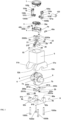
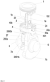
- FIGS. 1-10 illustrate a transmission assembly that transforms a linear reciprocating motion of a piston to an angular movement of a crank shaft, and that can fit inside a set of confined dimensions of a conventional cylinder block without altering the position of the crankshaft, while allowing for better torque conversion near the top dead center in the down stroke without compromising the engine's dimensions, wherein the transmission assembly is configured in accordance with embodiments of the present disclosure.
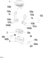
- the transmission assembly includes a pair of primary connecting rods Ia and Ib, wherein each may be connected from a first end 100a and 100b, respectively, to a piston head 1, and from a second end 101a and 101b to a secondary connecting rod 2 (e.g., see FIG. 5 ), wherein the connection to the piston head 1 may be achieved by a single degree-of-freedom joint, such as formed by a mating of the pin 102 with a corresponding hole formed in an underneath surface of the piston head 1.
- Each of the primary connecting rods la and lb may have a pair of circular openings 103a, 103b and 104a, 104b, respectively, wherein the openings 103b and 104b are in proximity to lower ends of the primary connecting rods la and lb, respectively (e.g., see FIG. 2 ).
- the secondary connecting rod 2 may include an upper portion 2a and a lower portion 2b that are separable from each other.
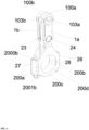
- the upper portion 2a of the secondary connecting rod 2 may include an elongated member 21 having two parallel opposed sides 22 and 23 with two laterally aligned pins 24 and 25 extending laterally outwardly from such an elongated member 21.
- the upper portion 2a of the secondary connecting rod 2 may also include two vertical extrusions 26 and 27 pointing downwards and defining a semi -circular space gap 28 between them, each of such vertical extrusions 26 and 27 may have a pass-through hole 260 and 270, respectively.
- the circular openings 103b and 104b are configured to receive the pins 24 and 25, respectively, thereby forming pin joints.
- the lower portion 2b may include two substantially parallel vertical extrusions 200a and 200b, each with a respective pass-through hole 201a and 201b, respectively.
- Such vertical extrusions 200a and 200b may be spaced apart and connected by a curved member 200c that defines a semi-circular space gap 200d between such vertical extrusions 200a and 200b.
- the pass-through holes 260 and 201b may be aligned to each other, and the pass-through holes 270 and 201a may be aligned to each other as well.
- the diameters of the semi-circular space gaps 28 and 200d may be substantially similar, wherein such gaps 28 and 200d form a substantially circular opening when the upper and lower portions 2a and 2b are connected with each other (e.g., see FIG. 6 ).
- Such a connection between the upper and lower portions 2a and 2b may be achieved by any suitable connection means, such as inserting a pair of bolts 2000a and 2000b, each through a pair of aligned holes 260, 201b, and 270, 201a, respectively, and securing each of such bolts 2000a and 2000b with nuts 2001a and 2001b, respectively.
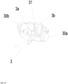
- the assembly may further include a controlling member 3, which has two opposed guiding rails 3 a and 3b extending inwardly along such controlling member 3 with a space gap 31 defined between such rails 3 a and 3b.
- the controlling member 3 may also include a pair of substantially coaxially aligned pins 30a and 30b extending laterally outwardly from the controlling member 3 in a substantially perpendicular direction to the two guiding rails 3a and 3b.
- one of the guiding rails 3a may be configured to facilitate force transmission from the pair of primary connecting rods la and lb to a crankshaft 6 in the downward stroke of the piston head 1.
- the guiding rails 3a and 3b passively control the additional degree of freedom provided by the addition of the secondary connecting rod 2, thus introducing a faster piston speed near Top Dead Center (TDC) of the cylinder block.
- TDC Top Dead Center
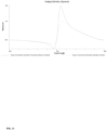
- FIG. 11 shows the difference of torque for one piston cycle (from Bottom Dead Center (BDC) to TDC to BDC) as a result of the difference in how mechanical arrangement in converting the available gas forces into a useful torque especially near TDC when high pressure introduced by combustion.
- BDC Bottom Dead Center
- the mechanical advantage of the present disclosure over the traditional slider-crank is achieved by converting more out of the available gas forces just after TDC by optimized fast piston motion, thus producing more torque compared to traditional slider-crank.
- the transmission assembly may further include a controlling member support element 4 with two substantially similar curved openings 4a and 4b, wherein each of such openings 4a and 4b may have a substantially trapezoidal profile combined with a semi-circular cut in proximity to a middle point of a base of the substantially trapezoidal profile.
- Each of the curved openings 4a and 4b may have a corresponding fixing element 40a and 40b, respectively, which are moveable laterally outwardly from the substantially trapezoidal portion of the openings 4a and 4b.
- Each of the fixing elements 40a and 40b may have a substantially trapezoidal shape with a substantially semi-circular cut 400a and 400b near a midpoint of a base of the substantially trapezoidal shape. Such fixing elements 40a and 40b may be configured to fit into the substantially trapezoidal portion of the openings 4a and 4b.
- the semi-circular cuts 400a and 400b of the fixing elements 40a and 40b, respectively, and the semi-circular portions of the openings 4a and 4b may have similar diameters, wherein such similar diameters may form two coaxially aligned circular openings configured to receive the pins 30a and 30b of the controlling member 3 to form pin joints when the fixing elements 40a and 40b are inserted in the openings 4a and 4b, respectively (e.g., see FIGS. 8-9 ).
- the controlling member support element 4 may be inserted inside a cylinder block 5 of an IC engine and may have a fixing mechanism 401 that helps in keeping such support element 4 static inside the cylinder block 5.
- a fixing mechanism 401 may include, but not limited to, a bolt that can be tightened up against an inside of the cylinder block 5 using a ratchet or an Allen key.
- the two pins 30a and 30b may be positioned on the semi-circular portions of the substantially similar curved openings 4a and 4b prior to the insertion of the fixing members 40a, 40b inside the substantially trapezoidal portions of such openings 4a, 4b.
- the transmission assembly may further include a crank shaft 6 laterally extending from a pair of mushroom-shaped counterweights 7a and 7b, wherein such counterweights are connected to each other by means of a crank shaft joint 8.
- the circular space gap formed by connecting the upper and lower portions 2a and 2b of the secondary connecting rod 2 (i.e., formed by mating the two semi-circular space gaps 28 and 200d) may be configured to receive the crank shaft joint 8.
- the cylinder block 5 may include an opening 50 (e.g., see, for example, FIG. 1 ) configured to receive the piston head 1, the primary connecting rods la and lb, the controlling member 3, the controlling member support element 4, and the secondary connecting rod 2.
- the cylinder block 5 may include a pair of vertically extruding members 51a and 51b pointing downwards, wherein each of such extruding members 51a and 51b has a semi-circular cut 52a and 52b, respectively, and a pair of parallel holes formed therein (not shown).
- the transmission assembly may further include a pair of cylinder caps 9, wherein each of such caps 9a and 9b corresponds to one of the vertically extruding members 51a and 51b, respectively, and may include a pair of pass-through parallel holes 90a, 91a, and 90b, 91b, respectively, and a semicircular cuts 92a and 92b, respectively.
- the holes of the vertically extruding members 51a and 51b and the pass-through holes 90a, 91a and 90b, 91b of the corresponding cylinder caps 9a and 9b may be aligned, wherein the cylinder caps 9a and 9b may be connected to the vertically extruding members 51a and 51b by any suitable connecting mechanism, such as bolts 1000a, 1000b, 1000c, and IOOOd.
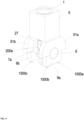
- the semi-circular cuts 52a, 92a and 52b, 92b may each form a circular opening when the cylinder caps 9a and 9b are connected to the vertically extruding members 51a and 51b, wherein such circular openings are configured to receive each end of the engine's crank shaft 6, such as illustrated in FIG. 4 .
- the elongated member 21 of the upper portion 2a of the secondary connecting rod 2 may be configured to reciprocate inside the space gap 31 of the controlling member 3 on the guiding rails 3 a and 3b.
- the controlling member 3 may be configured to oscillate about a central axis formed by the aligned pin joints 30a and 30b in a confined angle inside the controlling member support element 4.
- the oscillation of the controlling member 3 along with the reciprocation of the secondary connecting rod 2 may translate the reciprocating motion of the piston 1 to a rotation of the crank shaft 6, the counterweights 7a and 7b, and the crankshaft joint 8.
- the dimensions of all the above-mentioned components may be configured to allow the insertion of the piston 1, the primary connecting rods la and lb, the controlling member 3, the controlling member support element 4, and the secondary connecting rod 2 inside the cylinder block 5; and may be configured to allow for the oscillation of the controlling member 3, the rotation of the counter weights 7a and 7b, the crankshaft joint 8, and the crankshaft 6; and for the reciprocation of the piston 1 and the secondary connecting rod 2.
- the piston 1 may have less lateral surface area in comparison with conventional pistons, since the piston in the present disclosure may have lateral cuts. Such decrease in lateral surface area improves efficiency and lateral forces.
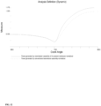
- FIG. 12 the difference in generated power as a result of the torque produced for one cycle (from BDC to TDC to BDC) is illustrated.
- the Figure gives an approximation for the net improvement of the power produced by mechanical advantage of the present disclosure, which is about 17.5%.
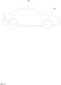
- FIG. 13 there is illustrated an exemplary vehicle 1300 that includes an engine 1301 suitable for driving wheels of the vehicle, wherein the engine 1301 is configured in accordance with embodiments of the present disclosure, wherein the engine 1301 implements the transmission assembly described herein with respect to FIGS. 1-12 .
- substantially refers to a degree of deviation that is sufficiently small so as to not measurably detract from the identified property or circumstance.
- the exact degree of deviation allowable may in some cases depend on the specific context.
Landscapes
- Engineering & Computer Science (AREA)
- General Engineering & Computer Science (AREA)
- Mechanical Engineering (AREA)
- Chemical & Material Sciences (AREA)
- Combustion & Propulsion (AREA)
- Shafts, Cranks, Connecting Bars, And Related Bearings (AREA)
Description
- This application claims priority from the
United States provisional patent application serial number 62/449,613 filed on January 24, 2017 - The present disclosure relates to an engine transmission assembly that transforms a linear reciprocating motion of a piston into an angular motion of a crankshaft.
- Conventional engines generally include of three major cases: a cylinder head sitting on top of a cylinder block, and a crank case. The cylinder block includes a plurality of cylinders, each having a piston reciprocating there through. The cylinder block along with the cylinder head forms a combustion chamber where fuel is combusted to cause the reciprocation of the pistons. In such conventional engines, the crank case includes a crankshaft connected to the piston through a transmission assembly that transforms the reciprocating motion of the pistons to torsion of the crankshaft.
A crankshaft piston interface is disclosed in the Application No.US8720410B2 known in the literature. Said crankshaft piston interface improves fuel efficiency and reduces harmful gas emission of the internal combustion engines. In order to realize this, the crankshaft piston mechanism is positioned between the piston and the crankshaft and provides movement transmission. A main link, a follower and a connecting rod are provided between the piston and the crankshaft. On said main link; a hole is provided for connecting to the piston, two positioning links are provided for connecting to the follower, and small diameter holes are provided which exist on the extensions. Thanks to this structure, the main link transfers the movement, received from the piston, towards the connecting rod. A hole is provided also on the connecting rod. This hole is essentially connected to the two positioning linkssuch that there is rotational freedom between the hole and the two extensions provided on the link. For this connection, a main link sleeve bearing is used which is in pin form. While the connecting rod is connected to the main link from one side, it is connected to the crankshaft from the other side. Thanks to this, movement transfer is provided between the two elements. The connecting rod can move in a compliant manner to the linear movement of the piston and the rotational movement of the crank.
A transmission mechanism is described in the Application No.US2015/053168A1 known in the literature. This transmission mechanism divides the conventional connecting rod, which exists between the crankshaft and the piston, into two parts and increases the efficiency of the internal combustion engine and the power output. One of the two parts, which exist on the connecting rod, is the first part and the other one is the second part. Said first part and said second part are connected to each other by means of pin joint. An oscillating rocker is used for providing movement of the connecting element. Thanks to this, degree of freedom is added to the controlled conventional piston arm, and engine efficiency is increased and fuel consumption is reduced. At the inner part of the rocker, grooves can be provided for allowing linear movement of the connecting rod. Sliding movement can be realized by engaging one edge of the connecting rod into said groove. - Conventional transmission assemblies in engines generally include a single connecting rod connected at one end to a piston head and to a crankshaft at the other end, wherein such assembly has only one degree-of-freedom.
- Therefore, it is an object of the present disclosure to provide a new assembly including moving and stationary parts, the assembly should transmit the reciprocating motion of an engine piston to a torsional motion of a crank shaft, allowing for better torque conversion near top dead center without compromising the engine dimensions.
- As another object of the present disclosure, there is provided an assembly that can fit inside the cylinders of the engine and a set of confined dimensions of a conventional cylinder block without altering the position of the crankshaft, allowing the assembly of the present disclosure to be used in retrofitting existing engines.
- Aspects of the present disclosure provide an assembly for an engine configured for linking a piston head to a crankshaft of the engine, the assembly include:
- a primary connecting rod configured to hingeably connect to said piston head;
- a secondary connecting rod comprising an upper portion and a lower portion, wherein the upper portion is hingeably connected to said primary connecting rod; a controlling member having a pair of opposing guiding rails and a pair of aligned lateral pins, wherein the controlling member is configured to receive a substantial part of the upper portion of said secondary connecting rod; and
- a controlling member support element configured to enclose the controlling member within a cylinder block of said engine, the controlling member support element comprising two aligned lateral openings configured to receive the pair of aligned lateral pins of the controlling member,
- wherein the upper and lower portions of the secondary connecting rod are configured to engage a crank shaft joint between a circular opening formed by a mating of the upper and lower portions of said secondary connecting rod.
- In some aspects, the upper portion of the secondary connecting rod may include an elongated member having a pin, wherein the pin may be inserted in an opening of the primary connecting rod.
- In other aspects, the upper portion of the secondary connecting rod may include two vertical extrusions that form a first semi-circular space gap between said vertical extrusions, and wherein the lower portion of the secondary connecting rod may include two parallel vertical extrusions that form a second semi-circular space gap between said parallel vertical extrusions, wherein the first and second semi-circular space gaps form the circular opening when the upper and lower portions of the secondary connecting rod are mated.
- In some aspects, the substantial part of the secondary connecting rod upper portion may be configured to slide inside said controlling member in a reciprocating motion.
- In other aspects, each of the two aligned lateral openings of said controlling member support element may include a trapezoidal opening with a semi-circular cut formed in proximity of a middle point of a base of said trapezoidal opening.
- In aspects of the present disclosure, the controlling member support element may further include a pair of fixing elements each having a trapezoidal shape with a semi-circular cut formed in proximity of a middle point of a base of said trapezoidal shape.
- in some aspects, two circular openings may be formed when the fixing elements are inserted inside said lateral openings of the controlling member support element, wherein the circular openings may be configured to receive the pair of aligned lateral pins of said controlling member to form a pair of aligned lateral pin joints.
- In aspects of the present disclosure, the circular openings of said controlling member support element and the pair of aligned lateral pin joints of the controlling member may be configured to allow for an oscillation of said controlling member.
- In some aspects, the piston head, the primary connecting rod, the secondary connecting rod, the controlling member, the controlling member support element, and the crank shaft joint may be enclosed in an engine cylinder block.
- In some aspects, the controlling member support element may further include a fixing mechanism configured to affix the controlling member support element inside said engine cylinder block.
- In some aspects, wherein said fixing mechanism may include a bolt configured to be tightened against said engine cylinder block.
- Other aspects of the present disclosure further provide an engine, which include:
- a piston;
- a crankshaft; and
- a transmission assembly linking the piston to the crankshaft, wherein the transmission assembly comprises:
- a primary connecting rod, each with a first opening configured to hingeably connect to said piston;
- a secondary connecting rod comprising an upper portion and a lower portion, wherein the upper portion is hingeably connected to second openings of said pair of primary connecting rods; a controlling member having a pair of opposing guiding rails and a pair of aligned lateral pins, wherein the controlling member is configured to receive a substantial part of the upper portion of said secondary connecting rod, wherein the substantial part of the upper portion of said secondary connecting rod is configured to slide inside said controlling member in a reciprocating motion; and
- a controlling member support element configured to enclose the controlling member within a cylinder block of said engine, the controlling member support element comprising two aligned lateral openings configured to receive the pair of aligned lateral pins of the controlling member,
- wherein the upper and lower portions of the secondary connecting rod may be configured to engage a joint of the crank shaft within a circular opening formed by a mating of the upper and lower portions of said secondary connecting rod, wherein the piston, the primary connecting rod, the secondary connecting rod, the controlling member, and the controlling member support element may be enclosed in the cylinder block of the engine.
- In aspects of the present disclosure, the upper portion of the secondary connecting rod of the engine's transmission assembly may include an elongated member having a pair of aligned pins, wherein the pair of aligned pins is inserted in second openings of the pair of primary connecting rods, wherein the upper portion of the secondary connecting rod may include two vertical extrusions that form a first semi-circular space gap between said vertical extrusions, and wherein the lower portion of the secondary connecting rod may include two parallel vertical extrusions that form a second semi-circular space gap between said parallel vertical extrusions, wherein the first and second semi-circular space gaps may form the circular opening when the upper and lower portions of the secondary connecting rod are mated.
- In accordance with aspects of the present disclosure, each of the two aligned lateral openings of said controlling member support element in the engine's transmission assembly may include a trapezoidal opening with a semi-circular cut formed in proximity of a middle point of a base of said trapezoidal opening, wherein the controlling member support element may further include a pair of fixing elements each having a trapezoidal shape with a semi-circular cut formed in proximity of a middle point of a base of said trapezoidal shape, wherein two circular openings may be formed when the fixing elements are inserted inside said lateral openings of the controlling member support element, wherein the circular openings may be configured to receive the pair of aligned lateral pins of said controlling member to form a pair of aligned lateral pin joints, wherein the circular openings of said controlling member support element and the pair of aligned lateral pin joints of the controlling member may be configured to allow for an oscillation of said controlling member.
- In aspects of the engine of the present disclosure, the controlling member support element may further include a fixing mechanism configured to affix the controlling member support element inside the cylinder block of the engine.
- Aspects of the present disclosure further provides a vehicle, which include:
- one or more wheels; and
- an engine suitable for driving the one or more wheels of the vehicle, wherein the engine may inlcude:
- a piston;
- a crankshaft; and
- a transmission assembly linking the piston to the crankshaft, wherein the transmission assembly comprises:
- a primary connecting rod, each with a first opening configured to hingeably connect to said piston;
- a secondary connecting rod comprising an upper portion and a lower portion, wherein the upper portion is hingeably connected to second openings of said pair of primary connecting rods;
- a controlling member having a pair of opposing guiding rails and a pair of aligned lateral pins, wherein the controlling member is configured to receive a substantial part of the upper portion of said secondary connecting rod, wherein the substantial part of the upper portion of said secondary connecting rod is configured to slide inside said controlling member in a reciprocating motion; and
- a controlling member support element configured to enclose the controlling member within a cylinder block of said engine, the controlling member support element comprising two aligned lateral openings configured to receive the pair of aligned lateral pins of the controlling member, wherein the upper and lower portions of the secondary connecting rod are configured to engage a joint of the crank shaft within a circular opening formed by a mating of the upper and lower portions of said secondary connecting rod, wherein the piston, the primary connecting rod, the secondary connecting rod, the controlling member, and the controlling member support element are enclosed in the cylinder block of the engine.
- In aspects of the present disclosure, the upper portion of the secondary connecting rod of the vehicle's engine may include an elongated member having a pair of aligned pins, wherein the pair of aligned pins may be inserted in second openings of the pair of primary connecting rods, wherein the upper portion of the secondary connecting rod may include two vertical extrusions that form a first semi-circular space gap between said vertical extrusions, and wherein the lower portion of the secondary connecting rod may include two parallel vertical extrusions that form a second semi-circular space gap between said parallel vertical extrusions, wherein the first and second semi-circular space gaps form the circular opening when the upper and lower portions of the secondary connecting rod are mated.
- In aspects of the present disclosure, each of the two aligned lateral openings of said controlling member support element in the vehicle's engine may include a trapezoidal opening with a semi-circular cut formed in proximity of a middle point of a base of said trapezoidal opening, wherein the controlling member support element may further include a pair of fixing elements each having a trapezoidal shape with a semi-circular cut formed in proximity of a middle point of a base of said trapezoidal shape, wherein two circular openings are formed when the fixing elements are inserted inside said lateral openings of the controlling member support element, wherein the circular openings are configured to receive the pair of aligned lateral pins of said controlling member to form a pair of aligned lateral pin joints, wherein the circular openings of said controlling member support element and the pair of aligned lateral pin joints of the controlling member may be configured to allow for an oscillation of said controlling member. BRIEF DESCRIPTION OF THE DRAWINGS
- The disclosure will now be described with reference to the accompanying drawings, which illustrate embodiments of the present disclosure, without restricting the scope of the disclosure, and in which:
-
FIG. 1 illustrates an exploded view of a transmission assembly for an engine configured in accordance with embodiments of the present disclosure. -
FIG. 2 illustrates an exploded view of a piston, primary connecting rods, controlling member, and controlling member support element of a transmission assembly for an engine configured in accordance with embodiments of the present disclosure. -
FIG. 3 illustrates an exploded view of a secondary connecting rod, an exemplary cylinder block, and an exemplary crank shaft of a transmission assembly for an engine configured in accordance with embodiments of the present disclosure. -
FIG. 4 illustrates a perspective view of a transmission assembly for an engine configured in accordance with embodiments of the present disclosure, the assembly being enclosed in an exemplary cylinder block. -
FIG. 5 illustrates a perspective view of secondary connecting rod of a transmission assembly for an engine configured in accordance with embodiments of the present disclosure. -
FIG. 6 illustrates a perspective view of a pair of primary connecting rods connected to a secondary connecting rod of a transmission assembly for an engine configured in accordance with embodiments of the present disclosure. -
FIG. 7 illustrates a perspective view of a pair of primary connecting rods connected to a secondary connecting rod that slides inside a controlling member of a transmission assembly for an engine configured in accordance with embodiments of the present disclosure. -
FIG. 8 illustrates a perspective view of a pair of primary connecting rods connected to a secondary connecting rod that is connected to a controlling member, the controlling member being connected to a controlling member support element of a transmission assembly for an engine configured in accordance with embodiments of the present disclosure. -
FIG. 9 illustrates a perspective view of a transmission assembly for an engine configured in accordance with embodiments of the present disclosure, the assembly being separated from the cylinder block. -
FIG. 10 illustrates a perspective view of a controlling member of a transmission assembly for an engine configured in accordance with embodiments of the present disclosure. -
FIG. 11 illustrates a plot comparing a torque produced by a transmission assembly configured in accordance with embodiments of the present disclosure and a torque produced by a conventional transmission assembly. -
FIG. 12 illustrates a plot comparing power generated by a transmission assembly configured in accordance embodiments of the present disclosure and power generated by a conventional transmission assembly. -
FIG. 13 illustrates an exemplary vehicle that includes an engine configured in accordance with embodiments of the present disclosure. -
FIGS. 1-10 illustrate a transmission assembly that transforms a linear reciprocating motion of a piston to an angular movement of a crank shaft, and that can fit inside a set of confined dimensions of a conventional cylinder block without altering the position of the crankshaft, while allowing for better torque conversion near the top dead center in the down stroke without compromising the engine's dimensions, wherein the transmission assembly is configured in accordance with embodiments of the present disclosure. - In accordance with embodiments of the present disclosure, the transmission assembly includes a pair of primary connecting rods Ia and Ib, wherein each may be connected from a
first end piston head 1, and from asecond end FIG. 5 ), wherein the connection to thepiston head 1 may be achieved by a single degree-of-freedom joint, such as formed by a mating of thepin 102 with a corresponding hole formed in an underneath surface of thepiston head 1. - Each of the primary connecting rods la and lb may have a pair of
circular openings openings FIG. 2 ). - In embodiments of the present disclosure, the secondary connecting rod 2 may include an
upper portion 2a and alower portion 2b that are separable from each other. Theupper portion 2a of the secondary connecting rod 2 may include anelongated member 21 having two parallelopposed sides pins elongated member 21. Theupper portion 2a of the secondary connecting rod 2 may also include twovertical extrusions circular space gap 28 between them, each of suchvertical extrusions hole 260 and 270, respectively. - In embodiments of the present disclosure, the
circular openings pins - In embodiments of the present disclosure, the
lower portion 2b may include two substantially parallelvertical extrusions hole vertical extrusions curved member 200c that defines asemi-circular space gap 200d between suchvertical extrusions - The pass-through
holes 260 and 201b may be aligned to each other, and the pass-throughholes - The diameters of the
semi-circular space gaps such gaps lower portions FIG. 6 ). Such a connection between the upper andlower portions bolts holes such bolts - Referring to
FIG. 10 , the assembly may further include a controllingmember 3, which has two opposed guidingrails member 3 with aspace gap 31 defined betweensuch rails member 3 may also include a pair of substantially coaxially alignedpins member 3 in a substantially perpendicular direction to the two guidingrails - Referring to
FIG. 9 , one of the guidingrails 3a may be configured to facilitate force transmission from the pair of primary connecting rods la and lb to acrankshaft 6 in the downward stroke of thepiston head 1. This is since the guidingrails crank shaft 6. The increase in torque at the TDC is illustrated inFIG. 11. FIG. 11 shows the difference of torque for one piston cycle (from Bottom Dead Center (BDC) to TDC to BDC) as a result of the difference in how mechanical arrangement in converting the available gas forces into a useful torque especially near TDC when high pressure introduced by combustion. The mechanical advantage of the present disclosure over the traditional slider-crank is achieved by converting more out of the available gas forces just after TDC by optimized fast piston motion, thus producing more torque compared to traditional slider-crank. - Referring to
FIG. 2 , for example, in accordance with embodiments of the present disclosure, the transmission assembly may further include a controllingmember support element 4 with two substantially similarcurved openings such openings curved openings corresponding fixing element openings elements semi-circular cut Such fixing elements openings semi-circular cuts elements openings pins member 3 to form pin joints when the fixingelements openings FIGS. 8-9 ). - It is appreciated that a function of the substantially trapezoidal portions of the
openings elements pins member 3 inside the engine'scylinder block 5. Therefore, in other embodiments, other profiles and shapes may be considered such as, but not limited to an inverted Y-shape, etc. - The controlling
member support element 4 may be inserted inside acylinder block 5 of an IC engine and may have afixing mechanism 401 that helps in keepingsuch support element 4 static inside thecylinder block 5. Such afixing mechanism 401 may include, but not limited to, a bolt that can be tightened up against an inside of thecylinder block 5 using a ratchet or an Allen key. - In embodiments of the present invention, the two
pins curved openings members such openings - Referring to
FIGS. 1 and3 , in accordance with embodiments of the present disclosure, the transmission assembly may further include acrank shaft 6 laterally extending from a pair of mushroom-shapedcounterweights crank shaft joint 8. - The circular space gap formed by connecting the upper and
lower portions semi-circular space gaps crank shaft joint 8. - The
cylinder block 5 may include an opening 50 (e.g., see, for example,FIG. 1 ) configured to receive thepiston head 1, the primary connecting rods la and lb, the controllingmember 3, the controllingmember support element 4, and the secondary connecting rod 2. Thecylinder block 5 may include a pair of vertically extrudingmembers such extruding members semi-circular cut - Referring to
FIG.3 , in accordance with embodiments of the present disclosure, the transmission assembly may further include a pair ofcylinder caps 9, wherein each ofsuch caps members parallel holes semicircular cuts - In embodiments of the present disclosure, the holes of the vertically extruding
members holes members bolts semi-circular cuts members shaft 6, such as illustrated inFIG. 4 . - The
elongated member 21 of theupper portion 2a of the secondary connecting rod 2 may be configured to reciprocate inside thespace gap 31 of the controllingmember 3 on the guidingrails - The controlling
member 3 may be configured to oscillate about a central axis formed by the alignedpin joints member support element 4. - In embodiments of the present disclosure, the oscillation of the controlling
member 3 along with the reciprocation of the secondary connecting rod 2 may translate the reciprocating motion of thepiston 1 to a rotation of thecrank shaft 6, thecounterweights crankshaft joint 8. - It should be appreciated that the dimensions of all the above-mentioned components may be configured to allow the insertion of the
piston 1, the primary connecting rods la and lb, the controllingmember 3, the controllingmember support element 4, and the secondary connecting rod 2 inside thecylinder block 5; and may be configured to allow for the oscillation of the controllingmember 3, the rotation of thecounter weights crankshaft joint 8, and thecrankshaft 6; and for the reciprocation of thepiston 1 and the secondary connecting rod 2. - In embodiments of the present disclosure, the
piston 1 may have less lateral surface area in comparison with conventional pistons, since the piston in the present disclosure may have lateral cuts. Such decrease in lateral surface area improves efficiency and lateral forces. - Referring to
FIG. 12 , the difference in generated power as a result of the torque produced for one cycle (from BDC to TDC to BDC) is illustrated. The Figure gives an approximation for the net improvement of the power produced by mechanical advantage of the present disclosure, which is about 17.5%. - Referring to
FIG. 13 , there is illustrated anexemplary vehicle 1300 that includes anengine 1301 suitable for driving wheels of the vehicle, wherein theengine 1301 is configured in accordance with embodiments of the present disclosure, wherein theengine 1301 implements the transmission assembly described herein with respect toFIGS. 1-12 . - The use of the term "and" in the claims is used to mean "and/or" unless explicitly indicated to refer to a collective nature only. The singular forms "a," "an," and "the" include plural referents unless the context clearly dictates otherwise.
- As used herein with respect to an identified property or circumstance, "substantially" refers to a degree of deviation that is sufficiently small so as to not measurably detract from the identified property or circumstance. The exact degree of deviation allowable may in some cases depend on the specific context.
Claims (10)
- An assembly for an engine (1301) configured for linking a piston head (1) to a crankshaft (6) of the engine (1301), the assembly comprising:a primary connecting rod (1a and 1b) configured to hingeably connect to said piston head (1);a secondary connecting rod (2) comprising an upper portion (2a) and a lower portion (2b), wherein the upper portion (2a) comprises an elongated member (21) having a pin (24 and 25) to hingeably connect the upper portion (2a) to the primary connecting rod (1a and 1b) by inserting such pin (24 and 25) in an opening (103a and 104b) of the primary connecting rod (1a and 1b), and wherein the upper and lower portions (2b) of the secondary connecting rod (2) are configured to engage a crank shaft joint (8) between a circular opening formed by mating of the upper and lower portions (2a and 2b) of said secondary connecting rod (2);characterized in havinga controlling member (3) having a pair of opposing guiding rails (3a and 3b) and a pair of aligned lateral pins (30a and 30b), wherein the controlling member (3) is configured to receive a substantial part of the upper portion (2a) of said secondary connecting rod (2); anda controlling member support element (4) configured to enclose the controlling member (3) within a cylinder block (5) of said engine (1301), the controlling member support element (4) comprising two aligned lateral openings (4a and 4b) configured to receive the pair of aligned lateral pins (30a and 30b) of the controlling member (3),the controlling member support element (4) further comprises a fixing mechanism (401) for affixing the controlling member support element (4) inside the cylinder block and for helping in keeping said controlling member support element (4) static inside the said cylinder block (5).
- The assembly of claims 1, further characterized in that the upper portion (2a) of the secondary connecting rod (2) comprises two vertical extrusions (26 and 27) that form a first semi-circular space gap between said vertical extrusions (26 and 27), and wherein the lower portion (2b) of the secondary connecting rod (2) comprises two parallel vertical extrusions (26 and 27) that form a second semi-circular space gap between said parallel vertical extrusions (26 and 27), wherein the first and second semi-circular space gaps (28 and 200d) form the circular opening when the upper and lower portions (2b) of the secondary connecting rod (2) are mated.
- The assembly of claim 1, further characterized in that the substantial part of the secondary connecting rod (2) upper portion (2a) is configured to slide inside said controlling member (3) in a reciprocating motion.
- The assembly of claim 1, further characterized in that each of the two aligned lateral openings (4a and 4b) of said controlling member (3) support element (4) comprises a trapezoidal opening with a semicircular cut formed in proximity of a middle point of a base of said trapezoidal opening.
- The assembly of claim 4, further characterized in that the controlling member (3) support element (4) further comprises a pair of fixing elements (40a and 40b) each having a trapezoidal shape with a semicircular cut formed in proximity of a middle point of a base of said trapezoidal shape.
- The assembly of claim 5, further characterized in that two circular openings (103a and 104b) are formed when the fixing elements (40a and 40b) are inserted inside said lateral openings of the controlling member (3) support element (4), wherein the circular openings (103a and 104b) are configured to receive the pair of aligned lateral pins (30a and 30b) of said controlling member (3) to form a pair of aligned lateral pin joints (30).
- The assembly of claim 6, further characterized in that the circular openings (103a and 104b) of said controlling member (3) support element (4) and the pair of aligned lateral pin joints (30) of the controlling member (3) are configured to allow for an oscillation of said controlling member (3).
- The assembly of claim 1, further characterized in that said fixing mechanism (401) comprises a bolt (1000a, 1000b, 1000c, and 1000d) configured to be tightened against said engine (1301) cylinder block (5).
- An engine comprising a piston head (1), a crankshaft (6), and an assembly connecting the piston head (1) to the crankshaft (6) according to any of the claims 1-8.
- A vehicle comprising: one or more wheels; and an engine according to claim 9.
Applications Claiming Priority (2)
| Application Number | Priority Date | Filing Date | Title |
|---|---|---|---|
| US201762449613P | 2017-01-24 | 2017-01-24 | |
| PCT/JO2018/050002 WO2018138748A2 (en) | 2017-01-24 | 2018-01-22 | Transmission assembly for an engine |
Publications (4)
| Publication Number | Publication Date |
|---|---|
| EP3704367A2 EP3704367A2 (en) | 2020-09-09 |
| EP3704367A4 EP3704367A4 (en) | 2021-03-10 |
| EP3704367C0 EP3704367C0 (en) | 2024-10-23 |
| EP3704367B1 true EP3704367B1 (en) | 2024-10-23 |
Family
ID=62978984
Family Applications (1)
| Application Number | Title | Priority Date | Filing Date |
|---|---|---|---|
| EP18743979.9A Active EP3704367B1 (en) | 2017-01-24 | 2018-01-22 | Transmission assembly for an engine |
Country Status (3)
| Country | Link |
|---|---|
| US (1) | US10934841B2 (en) |
| EP (1) | EP3704367B1 (en) |
| WO (1) | WO2018138748A2 (en) |
Families Citing this family (3)
| Publication number | Priority date | Publication date | Assignee | Title |
|---|---|---|---|---|
| JP6256551B1 (en) * | 2016-08-31 | 2018-01-10 | マツダ株式会社 | Connecting rod of engine |
| WO2024134701A1 (en) * | 2022-12-21 | 2024-06-27 | Mihyar Hashem | Transmission assembly for an engine and method of controlling the engine |
| WO2024194906A1 (en) * | 2023-03-22 | 2024-09-26 | Mihyar Tareq Raslan Hashem | Transmission assembly for an engine |
Family Cites Families (21)
| Publication number | Priority date | Publication date | Assignee | Title |
|---|---|---|---|---|
| US4266443A (en) * | 1978-07-06 | 1981-05-12 | Mcwhorter Edward M | Articulating guide spring |
| US4567866A (en) * | 1984-12-26 | 1986-02-04 | Hans Schubert | Piston crankshaft interface |
| DE3715391A1 (en) * | 1987-05-08 | 1988-12-01 | Gerhard Mederer | INTERNAL COMBUSTION ENGINE OR OTHER DRIVE |
| US5865092A (en) * | 1997-07-03 | 1999-02-02 | Woudwyk; Anthony D. | Engine connecting rod and double piston assembly |
| US6202622B1 (en) * | 1998-10-22 | 2001-03-20 | Antonio C. Raquiza, Jr. | Crank system for internal combustion engine |
| US20020043226A1 (en) * | 2000-10-17 | 2002-04-18 | Marion Gofron | Internal combustion engine featuring axially and opposingly arranged units |
| DE50104202D1 (en) * | 2001-03-19 | 2004-11-25 | Ford Global Tech Inc | Adjustable connecting rod |
| JP2003194172A (en) | 2001-12-12 | 2003-07-09 | Keisei Sai | Dual piston crank connecting rod power transmission mechanism |
| US6857401B1 (en) * | 2004-01-09 | 2005-02-22 | Ford Global Technologies, Llc | Variable compression ratio sensing system for internal combustion engine |
| US7028647B2 (en) * | 2004-01-09 | 2006-04-18 | Ford Global Technologies, Llc | Variable compression ratio connecting rod for internal combustion engine |
| US8720410B2 (en) * | 2012-10-08 | 2014-05-13 | Hans G. Schubert | Modified crankshaft piston interface for optimized cylinder pressure and torque output |
| US9243556B2 (en) * | 2013-08-20 | 2016-01-26 | Mohammad Hesham Fayiz Abazid | Transmission mechanism for a vehicle internal combustion engine |
| JP2015124635A (en) * | 2013-12-25 | 2015-07-06 | 三菱自動車工業株式会社 | Variable compression ratio device for internal combustion engine |
| JP6070683B2 (en) * | 2014-12-22 | 2017-02-01 | トヨタ自動車株式会社 | Variable length connecting rod and variable compression ratio internal combustion engine |
| US20170114826A1 (en) * | 2015-10-23 | 2017-04-27 | David Pienta | Telescopic Piston and Crankshaft Assembly |
| CN205654433U (en) | 2016-05-20 | 2016-10-19 | 西南交通大学 | Variable compression ratio engine |
| CN205663513U (en) | 2016-06-03 | 2016-10-26 | 尹建 | Serrated camshaft formula piston rod group |
| DE102016120975A1 (en) * | 2016-11-03 | 2018-05-03 | Avl List Gmbh | Length adjustable connecting rod with a cylinder-piston unit with oil filter |
| DE102017121630A1 (en) * | 2017-02-20 | 2018-08-23 | ECO Holding 1 GmbH | Connecting rod for a variable compression internal combustion engine |
| JP6528795B2 (en) * | 2017-02-28 | 2019-06-12 | トヨタ自動車株式会社 | Variable compression ratio mechanism and internal combustion engine |
| KR20200015304A (en) * | 2018-08-03 | 2020-02-12 | 현대자동차주식회사 | Variable compression ratio apparatus |
-
2018
- 2018-01-22 US US16/480,194 patent/US10934841B2/en active Active
- 2018-01-22 WO PCT/JO2018/050002 patent/WO2018138748A2/en not_active Ceased
- 2018-01-22 EP EP18743979.9A patent/EP3704367B1/en active Active
Also Published As
| Publication number | Publication date |
|---|---|
| US10934841B2 (en) | 2021-03-02 |
| WO2018138748A2 (en) | 2018-08-02 |
| EP3704367A2 (en) | 2020-09-09 |
| US20190368353A1 (en) | 2019-12-05 |
| WO2018138748A4 (en) | 2019-05-09 |
| WO2018138748A3 (en) | 2019-02-07 |
| EP3704367C0 (en) | 2024-10-23 |
| EP3704367A4 (en) | 2021-03-10 |
Similar Documents
| Publication | Publication Date | Title |
|---|---|---|
| EP3704367B1 (en) | Transmission assembly for an engine | |
| KR101318114B1 (en) | Rotary piston internal combustion engine | |
| EP2625393B1 (en) | Positive control (desmodromic) valve systems for internal combustion engines | |
| EP2021584B1 (en) | Internal combustion engine | |
| CN103797227B (en) | Crankpin including cam, connecting rod including follower, and internal combustion engine including crankpin and connecting rod | |
| JP3204412U (en) | Cam-driven reciprocating engine | |
| US7117828B2 (en) | Axial motors | |
| KR101236433B1 (en) | Solid cam type engine | |
| US9243556B2 (en) | Transmission mechanism for a vehicle internal combustion engine | |
| CN103429873B (en) | Crankpin including cam, connecting rod including follower, and internal combustion engine including crankpin and connecting rod | |
| WO2016140323A1 (en) | Drive device provided with xy-separating crank mechanism | |
| WO2024194906A1 (en) | Transmission assembly for an engine | |
| US20020088426A1 (en) | Connecting rod with increased effective length and engine using same | |
| JP2019148207A (en) | Variable compression ratio mechanism | |
| US8985070B2 (en) | Variable compression ratio V-type internal combustion engine | |
| EP1462631B1 (en) | Crankshaft coupling structure for use in an internal combustion engine | |
| US20170284545A1 (en) | Lightweight piston pin for piston inertial loading | |
| WO2024134701A1 (en) | Transmission assembly for an engine and method of controlling the engine | |
| US20260043373A1 (en) | Internal combustion engine | |
| JP2008544129A (en) | Piston assembly for barrel engine | |
| CN113811666B (en) | Piston device | |
| US20170284273A1 (en) | Lightweight power cell unit | |
| CN109469547B (en) | Horizontally-opposed engine with coaxially-arranged cylinders | |
| CN105143605B (en) | Internal combustion engine using orbital planetary gear transmission system | |
| RU2126087C1 (en) | Piston machine |
Legal Events
| Date | Code | Title | Description |
|---|---|---|---|
| STAA | Information on the status of an ep patent application or granted ep patent |
Free format text: STATUS: THE INTERNATIONAL PUBLICATION HAS BEEN MADE |
|
| PUAI | Public reference made under article 153(3) epc to a published international application that has entered the european phase |
Free format text: ORIGINAL CODE: 0009012 |
|
| STAA | Information on the status of an ep patent application or granted ep patent |
Free format text: STATUS: REQUEST FOR EXAMINATION WAS MADE |
|
| 17P | Request for examination filed |
Effective date: 20200623 |
|
| AK | Designated contracting states |
Kind code of ref document: A2 Designated state(s): AL AT BE BG CH CY CZ DE DK EE ES FI FR GB GR HR HU IE IS IT LI LT LU LV MC MK MT NL NO PL PT RO RS SE SI SK SM TR |
|
| A4 | Supplementary search report drawn up and despatched |
Effective date: 20210209 |
|
| RIC1 | Information provided on ipc code assigned before grant |
Ipc: F02B 41/04 20060101ALN20210203BHEP Ipc: F01B 9/02 20060101ALI20210203BHEP Ipc: F16C 7/06 20060101ALI20210203BHEP Ipc: F02B 75/32 20060101AFI20210203BHEP Ipc: F02B 75/04 20060101ALI20210203BHEP |
|
| RAP1 | Party data changed (applicant data changed or rights of an application transferred) |
Owner name: JAZARI POWERTRAIN OTOMOTIV TEKNOLOJI A.S. |
|
| RIN1 | Information on inventor provided before grant (corrected) |
Inventor name: ABAZID, MOHAMMAD |
|
| STAA | Information on the status of an ep patent application or granted ep patent |
Free format text: STATUS: EXAMINATION IS IN PROGRESS |
|
| 17Q | First examination report despatched |
Effective date: 20220113 |
|
| GRAP | Despatch of communication of intention to grant a patent |
Free format text: ORIGINAL CODE: EPIDOSNIGR1 |
|
| STAA | Information on the status of an ep patent application or granted ep patent |
Free format text: STATUS: GRANT OF PATENT IS INTENDED |
|
| RIC1 | Information provided on ipc code assigned before grant |
Ipc: F02B 41/04 20060101ALN20240507BHEP Ipc: F01B 9/02 20060101ALI20240507BHEP Ipc: F16C 7/06 20060101ALI20240507BHEP Ipc: F02B 75/04 20060101ALI20240507BHEP Ipc: F02B 75/32 20060101AFI20240507BHEP |
|
| INTG | Intention to grant announced |
Effective date: 20240527 |
|
| RIC1 | Information provided on ipc code assigned before grant |
Ipc: F02B 41/04 20060101ALN20240516BHEP Ipc: F01B 9/02 20060101ALI20240516BHEP Ipc: F16C 7/06 20060101ALI20240516BHEP Ipc: F02B 75/04 20060101ALI20240516BHEP Ipc: F02B 75/32 20060101AFI20240516BHEP |
|
| GRAS | Grant fee paid |
Free format text: ORIGINAL CODE: EPIDOSNIGR3 |
|
| GRAA | (expected) grant |
Free format text: ORIGINAL CODE: 0009210 |
|
| STAA | Information on the status of an ep patent application or granted ep patent |
Free format text: STATUS: THE PATENT HAS BEEN GRANTED |
|
| AK | Designated contracting states |
Kind code of ref document: B1 Designated state(s): AL AT BE BG CH CY CZ DE DK EE ES FI FR GB GR HR HU IE IS IT LI LT LU LV MC MK MT NL NO PL PT RO RS SE SI SK SM TR |
|
| REG | Reference to a national code |
Ref country code: GB Ref legal event code: FG4D |
|
| REG | Reference to a national code |
Ref country code: CH Ref legal event code: EP |
|
| REG | Reference to a national code |
Ref country code: DE Ref legal event code: R096 Ref document number: 602018075722 Country of ref document: DE |
|
| REG | Reference to a national code |
Ref country code: IE Ref legal event code: FG4D |
|
| U01 | Request for unitary effect filed |
Effective date: 20241101 |
|
| U07 | Unitary effect registered |
Designated state(s): AT BE BG DE DK EE FI FR IT LT LU LV MT NL PT RO SE SI Effective date: 20241112 |
|
| PG25 | Lapsed in a contracting state [announced via postgrant information from national office to epo] |
Ref country code: HR Free format text: LAPSE BECAUSE OF FAILURE TO SUBMIT A TRANSLATION OF THE DESCRIPTION OR TO PAY THE FEE WITHIN THE PRESCRIBED TIME-LIMIT Effective date: 20241023 Ref country code: IS Free format text: LAPSE BECAUSE OF FAILURE TO SUBMIT A TRANSLATION OF THE DESCRIPTION OR TO PAY THE FEE WITHIN THE PRESCRIBED TIME-LIMIT Effective date: 20250223 |
|
| PG25 | Lapsed in a contracting state [announced via postgrant information from national office to epo] |
Ref country code: ES Free format text: LAPSE BECAUSE OF FAILURE TO SUBMIT A TRANSLATION OF THE DESCRIPTION OR TO PAY THE FEE WITHIN THE PRESCRIBED TIME-LIMIT Effective date: 20241023 |
|
| PG25 | Lapsed in a contracting state [announced via postgrant information from national office to epo] |
Ref country code: NO Free format text: LAPSE BECAUSE OF FAILURE TO SUBMIT A TRANSLATION OF THE DESCRIPTION OR TO PAY THE FEE WITHIN THE PRESCRIBED TIME-LIMIT Effective date: 20250123 |
|
| PG25 | Lapsed in a contracting state [announced via postgrant information from national office to epo] |
Ref country code: GR Free format text: LAPSE BECAUSE OF FAILURE TO SUBMIT A TRANSLATION OF THE DESCRIPTION OR TO PAY THE FEE WITHIN THE PRESCRIBED TIME-LIMIT Effective date: 20250124 |
|
| PG25 | Lapsed in a contracting state [announced via postgrant information from national office to epo] |
Ref country code: PL Free format text: LAPSE BECAUSE OF FAILURE TO SUBMIT A TRANSLATION OF THE DESCRIPTION OR TO PAY THE FEE WITHIN THE PRESCRIBED TIME-LIMIT Effective date: 20241023 |
|
| PG25 | Lapsed in a contracting state [announced via postgrant information from national office to epo] |
Ref country code: RS Free format text: LAPSE BECAUSE OF FAILURE TO SUBMIT A TRANSLATION OF THE DESCRIPTION OR TO PAY THE FEE WITHIN THE PRESCRIBED TIME-LIMIT Effective date: 20250123 |
|
| PG25 | Lapsed in a contracting state [announced via postgrant information from national office to epo] |
Ref country code: SM Free format text: LAPSE BECAUSE OF FAILURE TO SUBMIT A TRANSLATION OF THE DESCRIPTION OR TO PAY THE FEE WITHIN THE PRESCRIBED TIME-LIMIT Effective date: 20241023 |
|
| PG25 | Lapsed in a contracting state [announced via postgrant information from national office to epo] |
Ref country code: SK Free format text: LAPSE BECAUSE OF FAILURE TO SUBMIT A TRANSLATION OF THE DESCRIPTION OR TO PAY THE FEE WITHIN THE PRESCRIBED TIME-LIMIT Effective date: 20241023 |
|
| PG25 | Lapsed in a contracting state [announced via postgrant information from national office to epo] |
Ref country code: CZ Free format text: LAPSE BECAUSE OF FAILURE TO SUBMIT A TRANSLATION OF THE DESCRIPTION OR TO PAY THE FEE WITHIN THE PRESCRIBED TIME-LIMIT Effective date: 20241023 |
|
| PLBE | No opposition filed within time limit |
Free format text: ORIGINAL CODE: 0009261 |
|
| REG | Reference to a national code |
Ref country code: CH Ref legal event code: PL |
|
| STAA | Information on the status of an ep patent application or granted ep patent |
Free format text: STATUS: NO OPPOSITION FILED WITHIN TIME LIMIT |
|
| PG25 | Lapsed in a contracting state [announced via postgrant information from national office to epo] |
Ref country code: MC Free format text: LAPSE BECAUSE OF FAILURE TO SUBMIT A TRANSLATION OF THE DESCRIPTION OR TO PAY THE FEE WITHIN THE PRESCRIBED TIME-LIMIT Effective date: 20241023 |
|
| U90 | Renewal fees not paid: noting of loss of rights |
Free format text: RENEWAL FEE NOT PAID FOR YEAR 08 Effective date: 20250819 |
|
| GBPC | Gb: european patent ceased through non-payment of renewal fee |
Effective date: 20250123 |
|
| 26N | No opposition filed |
Effective date: 20250724 |
|
| PG25 | Lapsed in a contracting state [announced via postgrant information from national office to epo] |
Ref country code: GB Free format text: LAPSE BECAUSE OF NON-PAYMENT OF DUE FEES Effective date: 20250123 |
|
| PG25 | Lapsed in a contracting state [announced via postgrant information from national office to epo] |
Ref country code: CH Free format text: LAPSE BECAUSE OF NON-PAYMENT OF DUE FEES Effective date: 20250131 |
|
| U93 | Unitary patent lapsed |
Free format text: RENEWAL FEE NOT PAID Effective date: 20250131 |
|
| PG25 | Lapsed in a contracting state [announced via postgrant information from national office to epo] |
Ref country code: IE Free format text: LAPSE BECAUSE OF NON-PAYMENT OF DUE FEES Effective date: 20250122 |