EP3704064B1 - Chlorination systems - Google Patents
Chlorination systems Download PDFInfo
- Publication number
- EP3704064B1 EP3704064B1 EP18815054.4A EP18815054A EP3704064B1 EP 3704064 B1 EP3704064 B1 EP 3704064B1 EP 18815054 A EP18815054 A EP 18815054A EP 3704064 B1 EP3704064 B1 EP 3704064B1
- Authority
- EP
- European Patent Office
- Prior art keywords
- water
- chlorinator
- salt
- housing
- gas trap
- Prior art date
- Legal status (The legal status is an assumption and is not a legal conclusion. Google has not performed a legal analysis and makes no representation as to the accuracy of the status listed.)
- Active
Links
Images


Classifications
-
- C—CHEMISTRY; METALLURGY
- C02—TREATMENT OF WATER, WASTE WATER, SEWAGE, OR SLUDGE
- C02F—TREATMENT OF WATER, WASTE WATER, SEWAGE, OR SLUDGE
- C02F1/00—Treatment of water, waste water, or sewage
- C02F1/46—Treatment of water, waste water, or sewage by electrochemical methods
- C02F1/4602—Treatment of water, waste water, or sewage by electrochemical methods for prevention or elimination of deposits
-
- C—CHEMISTRY; METALLURGY
- C02—TREATMENT OF WATER, WASTE WATER, SEWAGE, OR SLUDGE
- C02F—TREATMENT OF WATER, WASTE WATER, SEWAGE, OR SLUDGE
- C02F1/00—Treatment of water, waste water, or sewage
- C02F1/46—Treatment of water, waste water, or sewage by electrochemical methods
- C02F1/461—Treatment of water, waste water, or sewage by electrochemical methods by electrolysis
- C02F1/467—Treatment of water, waste water, or sewage by electrochemical methods by electrolysis by electrochemical disinfection; by electrooxydation or by electroreduction
- C02F1/4672—Treatment of water, waste water, or sewage by electrochemical methods by electrolysis by electrochemical disinfection; by electrooxydation or by electroreduction by electrooxydation
- C02F1/4674—Treatment of water, waste water, or sewage by electrochemical methods by electrolysis by electrochemical disinfection; by electrooxydation or by electroreduction by electrooxydation with halogen or compound of halogens, e.g. chlorine, bromine
-
- C—CHEMISTRY; METALLURGY
- C25—ELECTROLYTIC OR ELECTROPHORETIC PROCESSES; APPARATUS THEREFOR
- C25B—ELECTROLYTIC OR ELECTROPHORETIC PROCESSES FOR THE PRODUCTION OF COMPOUNDS OR NON-METALS; APPARATUS THEREFOR
- C25B1/00—Electrolytic production of inorganic compounds or non-metals
- C25B1/01—Products
- C25B1/24—Halogens or compounds thereof
- C25B1/26—Chlorine; Compounds thereof
-
- C—CHEMISTRY; METALLURGY
- C25—ELECTROLYTIC OR ELECTROPHORETIC PROCESSES; APPARATUS THEREFOR
- C25B—ELECTROLYTIC OR ELECTROPHORETIC PROCESSES FOR THE PRODUCTION OF COMPOUNDS OR NON-METALS; APPARATUS THEREFOR
- C25B15/00—Operating or servicing cells
- C25B15/02—Process control or regulation
-
- C—CHEMISTRY; METALLURGY
- C25—ELECTROLYTIC OR ELECTROPHORETIC PROCESSES; APPARATUS THEREFOR
- C25B—ELECTROLYTIC OR ELECTROPHORETIC PROCESSES FOR THE PRODUCTION OF COMPOUNDS OR NON-METALS; APPARATUS THEREFOR
- C25B15/00—Operating or servicing cells
- C25B15/02—Process control or regulation
- C25B15/023—Measuring, analysing or testing during electrolytic production
-
- E—FIXED CONSTRUCTIONS
- E04—BUILDING
- E04H—BUILDINGS OR LIKE STRUCTURES FOR PARTICULAR PURPOSES; SWIMMING OR SPLASH BATHS OR POOLS; MASTS; FENCING; TENTS OR CANOPIES, IN GENERAL
- E04H4/00—Swimming or splash baths or pools
- E04H4/12—Devices or arrangements for circulating water, i.e. devices for removal of polluted water, cleaning baths or for water treatment
- E04H4/1281—Devices for distributing chemical products in the water of swimming pools
-
- C—CHEMISTRY; METALLURGY
- C02—TREATMENT OF WATER, WASTE WATER, SEWAGE, OR SLUDGE
- C02F—TREATMENT OF WATER, WASTE WATER, SEWAGE, OR SLUDGE
- C02F2103/00—Nature of the water, waste water, sewage or sludge to be treated
- C02F2103/42—Nature of the water, waste water, sewage or sludge to be treated from bathing facilities, e.g. swimming pools
-
- C—CHEMISTRY; METALLURGY
- C02—TREATMENT OF WATER, WASTE WATER, SEWAGE, OR SLUDGE
- C02F—TREATMENT OF WATER, WASTE WATER, SEWAGE, OR SLUDGE
- C02F2201/00—Apparatus for treatment of water, waste water or sewage
- C02F2201/46—Apparatus for electrochemical processes
- C02F2201/461—Electrolysis apparatus
- C02F2201/46105—Details relating to the electrolytic devices
- C02F2201/4612—Controlling or monitoring
- C02F2201/46125—Electrical variables
- C02F2201/4614—Current
-
- C—CHEMISTRY; METALLURGY
- C02—TREATMENT OF WATER, WASTE WATER, SEWAGE, OR SLUDGE
- C02F—TREATMENT OF WATER, WASTE WATER, SEWAGE, OR SLUDGE
- C02F2201/00—Apparatus for treatment of water, waste water or sewage
- C02F2201/46—Apparatus for electrochemical processes
- C02F2201/461—Electrolysis apparatus
- C02F2201/46105—Details relating to the electrolytic devices
- C02F2201/4612—Controlling or monitoring
- C02F2201/46145—Fluid flow
-
- C—CHEMISTRY; METALLURGY
- C02—TREATMENT OF WATER, WASTE WATER, SEWAGE, OR SLUDGE
- C02F—TREATMENT OF WATER, WASTE WATER, SEWAGE, OR SLUDGE
- C02F2209/00—Controlling or monitoring parameters in water treatment
- C02F2209/02—Temperature
-
- C—CHEMISTRY; METALLURGY
- C02—TREATMENT OF WATER, WASTE WATER, SEWAGE, OR SLUDGE
- C02F—TREATMENT OF WATER, WASTE WATER, SEWAGE, OR SLUDGE
- C02F2209/00—Controlling or monitoring parameters in water treatment
- C02F2209/40—Liquid flow rate
-
- C—CHEMISTRY; METALLURGY
- C02—TREATMENT OF WATER, WASTE WATER, SEWAGE, OR SLUDGE
- C02F—TREATMENT OF WATER, WASTE WATER, SEWAGE, OR SLUDGE
- C02F2303/00—Specific treatment goals
- C02F2303/04—Disinfection
Definitions
- This invention relates to chlorination systems and more particularly, but not necessarily exclusively, to salt-water chlorinators having multiple, spaced gas traps, each with a corresponding water-flow sensor.
- chlorinators utilize a "gas trap" in an effort to determine whether water is flowing through a cell.
- chloride ions are converted into chlorine gas (which dissolves into water ultimately to form sodium hypochlorite), with hydrogen gas being liberated at the cathode of the cell.
- chlorine gas which dissolves into water ultimately to form sodium hypochlorite
- hydrogen gas being liberated at the cathode of the cell.
- gas-trap sensors Because sensing in these situations requires gas build-up within a cell, gas-trap sensors generally have slow response times. Moreover, they may be subject to false negative readings during periods of low-flow, as water may continue to flow yet at a velocity inadequate to prevent gas accumulation. Formation of a gas trap within a cell also typically requires installation of a chlorinator in a particular orientation which might not permit it to be plumbed conveniently into a pool water-circulation system.
- the present invention seeks to resolve some of the performance issues associated with existing salt-water chlorinators for swimming pools and spas.
- the present invention relates to a salt-water chlorinator comprising sensors according to claim 1.
- logic may be employed requiring both (or all) sensors to sense the existence of water flow before providing electricity to the cell.
- the mechanical barrier may inhibit any scale build up from approaching at least one flow sensor.
- the chlorinator housing may be configured so as to route, or focus, gases toward a small-sized, high point thereof. As gas accumulates in the small area, it quickly displaces water so that the water line recedes below a sensor. In this manner, rapid determination of a lack of water flow may be made by the associated sensor.
- Chlorinators of the present invention may include a level indicator designed to alert an installer or user when a cell either is not level or is installed in an incorrect orientation.
- the innovative systems additionally may automatically limit chlorine output (below maximum) of the cells when water or air temperatures are low. Chlorine demand by a pool or spa typically is lower at low temperatures, and reducing output helps mitigate reduction in cell life otherwise risked through low-temperature operation.
- FIGS. 1-4 illustrate various of these features of the invention.
- chlorinator 10 includes housing 14 and electrolysis cell 18.
- Housing 14 defines inlet 22 and outlet 26, through which circulating water of a swimming pool or spa may pass. The pressurized water hence flows through housing 14 in the direction of arrow A of FIG. 1 .
- Cell 18 includes an electrode assembly comprising at least anode plates 30 and a cathode. Also shown are two gas traps 1, 2 spaced within housing 14. Each trap 1,2 includes a corresponding flow sensor, which therefore also will be spaced within the housing 14. Electronics of chlorinator 10 may process information provided by either or both of the flow sensors to assess water-flow conditions of cell 18. In some cases, for example, logic may be utilized requiring both sensors to sense the existence of water flow before electricity is provided to cell 18. The electronics may be present on a printed circuit board (PCB) similar to that of the Davidson patent and positioned within housing 14; alternatively, they may be positioned remotely and communicate (via wire or wirelessly) with the flow sensors of traps 1, 2.
- PCB printed circuit board
- barrier 34 physically separating gas trap 1 from the electrode assembly.
- Barrier 34 may be any mechanical device suitable for inhibiting scale from approaching or contacting the flow sensor of gas trap 1.
- FIG. 3 illustrates that barrier 34 is positioned between inlet 22 and the electrode assembly and may be formed as a scoop configured also to channel pool water toward gas trap 1. By virtue of the existence and placement of barrier 34, gas trap 1 may be considered relatively "safe" from detrimental contact by scale.
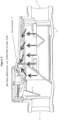
- FIG. 2 illustrates a design of housing 14 causing gases to converge at or near the sensor (denoted "Gas Sensor 2") associated with gas trap 2.
- gases may be routed, or focused, toward a small-sized, high point of housing 14 forming trap 2.
- Such routing is schematically illustrated by the arrows of FIG. 2 .
- gas trap 2 may be considered relatively "fast,” or “fast acting,” in use.
- FIG. 3 depicts ramp 38 directing water flowing within housing 14 toward gas trap 2.
- Ramp 38 (or any other appropriate geometric restriction) hence may increase flow rate to the gas trap 2, removing gas having accumulated there as generated by the plates of the chlorinator 10.
- Such structure enhances the ability to detect occurrence of water flow even when the flow is low.
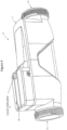
- FIG. 4 illustrates an exemplary level/orientation sensor or indicator 42 placed on an exterior surface 46 of housing 14 of chlorinator 10.
- Orientation indicator 42 may provide a visual (or other) indication of the level/orientation status of the housing 14 as, for example, by illuminating a light when housing 14 is oriented correctly. It thus may alert an installer or user when chlorinator 10 either is not level or is installed correctly. (As an example of improper installation orientation, if chlorinator 10 is installed so that gas traps 1 and 2 are not at or near the top of housing 14, gasses may not travel there.)
Landscapes
- Chemical & Material Sciences (AREA)
- Engineering & Computer Science (AREA)
- Chemical Kinetics & Catalysis (AREA)
- Electrochemistry (AREA)
- Organic Chemistry (AREA)
- Water Supply & Treatment (AREA)
- Materials Engineering (AREA)
- Metallurgy (AREA)
- Architecture (AREA)
- Environmental & Geological Engineering (AREA)
- Hydrology & Water Resources (AREA)
- Life Sciences & Earth Sciences (AREA)
- General Chemical & Material Sciences (AREA)
- Automation & Control Theory (AREA)
- Civil Engineering (AREA)
- Structural Engineering (AREA)
- Inorganic Chemistry (AREA)
- Analytical Chemistry (AREA)
- Electrolytic Production Of Non-Metals, Compounds, Apparatuses Therefor (AREA)
Description
- This application claims the benefit of and priority to
U.S. Provisional Patent Application Serial No. 62/580,200, filed November 1, 2017 - This invention relates to chlorination systems and more particularly, but not necessarily exclusively, to salt-water chlorinators having multiple, spaced gas traps, each with a corresponding water-flow sensor.
-
U.S. Patent No. 8,920,615 to Davidson, et al describes one version of a salt-water chlorinator for swimming pools and spas. Recognized by the Davidson patent in connection with chlorinators "is that scale (principally calcium salts) deposits and builds up on the cathode" of an electrolysis cell of the chlorinator, "thus reducing the efficiency of chlorine production by the cell." See Davidson, col. 1, 11. 29-32. Accordingly, proposed in the Davidson patent are mechanical scrapers for removing scale from cathodes of the cells. - Also disclosed in the Davidson patent is use of a sensor within a housing of a chlorinator "to sense flowíno flow conditions in the electrolysis cell." See id., col. 3, 11. 37-38. Although not addressed in the Davidson patent, well known in the pool and spa industry is that scale build-up may retain moisture. If scale deposits are present especially between a cathode and a flow sensor, their retained moisture may deceive the sensor into believing water is flowing through a cell when it, in fact, is not Continuing to operate a chlorinator without water flow through its electrolysis cell may prove to be a safety hazard and thus is undesirable.
- Some existing chlorinators utilize a "gas trap" in an effort to determine whether water is flowing through a cell. As electrolytic reactions occur within the cell, chloride ions are converted into chlorine gas (which dissolves into water ultimately to form sodium hypochlorite), with hydrogen gas being liberated at the cathode of the cell. When not adequately removed from the cell by flowing water, these gasses accumulate and may be sensed, directly or indirectly, as indicating lack of water flow through the cell.
- Because sensing in these situations requires gas build-up within a cell, gas-trap sensors generally have slow response times. Moreover, they may be subject to false negative readings during periods of low-flow, as water may continue to flow yet at a velocity inadequate to prevent gas accumulation. Formation of a gas trap within a cell also typically requires installation of a chlorinator in a particular orientation which might not permit it to be plumbed conveniently into a pool water-circulation system.
-
- The present invention seeks to resolve some of the performance issues associated with existing salt-water chlorinators for swimming pools and spas. The present invention relates to a salt-water chlorinator comprising sensors according to
claim 1. - If desired, logic may be employed requiring both (or all) sensors to sense the existence of water flow before providing electricity to the cell.
- The mechanical barrier may inhibit any scale build up from approaching at least one flow sensor. Additionally, the chlorinator housing may be configured so as to route, or focus, gases toward a small-sized, high point thereof. As gas accumulates in the small area, it quickly displaces water so that the water line recedes below a sensor. In this manner, rapid determination of a lack of water flow may be made by the associated sensor.
- A geometric restriction, such as a ramp, may be utilized to increase water flow to one or more of the gas traps. The increased flow tends to displace the accumulated gas more quickly, resulting in a cell design able to indicate occurrence of water flow even when the flow is low. Chlorinators of the present invention also may include a level indicator designed to alert an installer or user when a cell either is not level or is installed in an incorrect orientation. The innovative systems additionally may automatically limit chlorine output (below maximum) of the cells when water or air temperatures are low. Chlorine demand by a pool or spa typically is lower at low temperatures, and reducing output helps mitigate reduction in cell life otherwise risked through low-temperature operation.
- It thus is an object of the present invention to provide chlorinators utilizing more than one gas trap within their cells.
- It is an additional optional, non-exclusive object of the present invention to provide chlorinators whose housings may be configured so as to route, or focus, gases toward a high point thereof.
- It is also an object of the present invention to provide chlorinators having more than one water flow sensor, with the sensors being spaced within the cells.
- It is another optional, non-exclusive object of the present invention to provide chlorinators configured to require sensing of water flow at more than one location within a cell in order to allow or continue electricity supply to or within the cell.
- It is a further object of the present invention to provide chlorinators including barriers designed to inhibit scale build up from approaching at least some water flow sensors.
- It is, moreover, an optional, non-exclusive object of the present invention to provide chlorinators comprising geometric restrictions increasing water flow to at least some gas traps.
- It is yet another optional, non-exclusive object of the present invention to provide chlorinators including a level indicator.
- Other objects, features, and advantages of the present invention will be apparent to those skilled in the relevant art with reference to the remaining text and the drawings of this application.
-
-
FIGS. 1-3 are schematicized sectional views of a chlorinator consistent with the present invention. -
FIG. 4 is a perspective view of the chlorinator ofFIGS. 1-3 illustrating, among other things, a level or orientation indicator. -
FIGS. 1-4 illustrate various of these features of the invention. In a depicted embodiment of the invention,chlorinator 10 includeshousing 14 andelectrolysis cell 18.Housing 14 definesinlet 22 andoutlet 26, through which circulating water of a swimming pool or spa may pass. The pressurized water hence flows throughhousing 14 in the direction of arrow A ofFIG. 1 . -
Cell 18 includes an electrode assembly comprising at leastanode plates 30 and a cathode. Also shown are twogas traps housing 14. Eachtrap housing 14. Electronics ofchlorinator 10 may process information provided by either or both of the flow sensors to assess water-flow conditions ofcell 18. In some cases, for example, logic may be utilized requiring both sensors to sense the existence of water flow before electricity is provided tocell 18. The electronics may be present on a printed circuit board (PCB) similar to that of the Davidson patent and positioned withinhousing 14; alternatively, they may be positioned remotely and communicate (via wire or wirelessly) with the flow sensors oftraps - Additionally depicted in
FIG. 1 isbarrier 34 physically separatinggas trap 1 from the electrode assembly.Barrier 34 may be any mechanical device suitable for inhibiting scale from approaching or contacting the flow sensor ofgas trap 1.FIG. 3 illustrates thatbarrier 34 is positioned betweeninlet 22 and the electrode assembly and may be formed as a scoop configured also to channel pool water towardgas trap 1. By virtue of the existence and placement ofbarrier 34,gas trap 1 may be considered relatively "safe" from detrimental contact by scale. -
FIG. 2 illustrates a design ofhousing 14 causing gases to converge at or near the sensor (denoted "Gas Sensor 2") associated withgas trap 2. In essence, gases may be routed, or focused, toward a small-sized, high point ofhousing 14 formingtrap 2. Such routing is schematically illustrated by the arrows ofFIG. 2 . In this way, accumulating gas may quickly displace any water present so that the water line recedes below- the sensor, allowing the sensor rapidly to determine a low (or lack of) flow condition withincell 14. Accordingly,gas trap 2 may be considered relatively "fast," or "fast acting," in use. -
FIG. 3 depictsramp 38 directing water flowing withinhousing 14 towardgas trap 2. Ramp 38 (or any other appropriate geometric restriction) hence may increase flow rate to thegas trap 2, removing gas having accumulated there as generated by the plates of thechlorinator 10. Such structure enhances the ability to detect occurrence of water flow even when the flow is low. -
FIG. 4 , finally, illustrates an exemplary level/orientation sensor orindicator 42 placed on anexterior surface 46 ofhousing 14 ofchlorinator 10.Orientation indicator 42 may provide a visual (or other) indication of the level/orientation status of thehousing 14 as, for example, by illuminating a light whenhousing 14 is oriented correctly. It thus may alert an installer or user whenchlorinator 10 either is not level or is installed correctly. (As an example of improper installation orientation, ifchlorinator 10 is installed so that gas traps 1 and 2 are not at or near the top ofhousing 14, gasses may not travel there.) - The foregoing is provided for purposes of illustrating, explaining, and describing embodiments of the present invention. Modifications and adaptations to these embodiments will be apparent to those skilled in the art mid without departing from the scope of the claims. Finally, references to "pools" and "swimming pools" herein may also refer to spas or other water containing vessels used for recreation or therapy and in connection with salt-water chlorinators are used.
Claims (8)
- A salt-water chlorinator (10) comprising:a. a housing (14) defining a water inlet (22) and a water outlet (26);b. an electrolysis cell (18), at least a portion of which is positioned for use within the housing (14), said electrolysis cell including an electrode assembly;c. a first gas trap (1) comprising a first water flow sensor positioned within the housing (14); andd. a second gas trap (2) (i) spaced from the first gas trap (1) and (ii) comprising a second water flow sensor positioned within the housing (14),wherein the salt-water chlorinator (10) comprises a barrier (34) physically separating the first gas trap (1) from the electrode assembly and positioned between the water inlet (22) and the electrode assembly.
- A salt-water chlorinator (10) according to claim 1 in which the barrier (34) is formed as a scoop configured to channel water toward the first gas trap (1).
- A salt-water chlorinator (10) according to claim 1, further comprising a ramp (38) configured to direct water toward the second gas trap (2).
- A salt-water chlorinator (10) according to claim 1, further comprising means (42) for indicating orientation of the housing (14).
- A salt-water chlorinator (10) according to claim 1 in which (a) the housing (14) further defines an interior region forming a high point thereof and (b) the second gas trap (2) is located at or adjacent the high point.
- A salt-water chlorinator (10) according to claim 1, further comprising electronics configured to limit generated chlorine as a function of temperature.
- A salt-water chlorinator (10) according to claim 1, further comprising electronics configured to prevent supply of electricity to the electrolysis cell (18) unless both the first and second water flow sensors sense water flow.
- A salt-water chlorinator (10) according to claim 1 in which the barrier (34) is formed as a scoop configured to channel water toward the first gas trap (1), and in which said salt-water chlorinator further comprises:f. a ramp (38) configured to direct water toward the second gas trap (2); andg. means (42) for indicating orientation of the housing (14).
Applications Claiming Priority (2)
| Application Number | Priority Date | Filing Date | Title |
|---|---|---|---|
| US201762580200P | 2017-11-01 | 2017-11-01 | |
| PCT/US2018/058151 WO2019089548A1 (en) | 2017-11-01 | 2018-10-30 | Chlorination systems |
Publications (2)
| Publication Number | Publication Date |
|---|---|
| EP3704064A1 EP3704064A1 (en) | 2020-09-09 |
| EP3704064B1 true EP3704064B1 (en) | 2024-10-23 |
Family
ID=64607289
Family Applications (1)
| Application Number | Title | Priority Date | Filing Date |
|---|---|---|---|
| EP18815054.4A Active EP3704064B1 (en) | 2017-11-01 | 2018-10-30 | Chlorination systems |
Country Status (5)
| Country | Link |
|---|---|
| US (1) | US10981808B2 (en) |
| EP (1) | EP3704064B1 (en) |
| AU (1) | AU2018359245C1 (en) |
| ES (1) | ES2997962T3 (en) |
| WO (1) | WO2019089548A1 (en) |
Families Citing this family (1)
| Publication number | Priority date | Publication date | Assignee | Title |
|---|---|---|---|---|
| US10904851B1 (en) | 2020-01-21 | 2021-01-26 | Cisco Technology, Inc. | Systems and methods for determining locations of access points |
Family Cites Families (8)
| Publication number | Priority date | Publication date | Assignee | Title |
|---|---|---|---|---|
| AU745501C (en) | 1998-12-07 | 2003-01-16 | Integrated Pool Products (Proprietary) Limited | Water chlorinator |
| AU2003902831A0 (en) * | 2003-06-06 | 2003-06-26 | Ben Bremauer | Electrolytic sanitiser generator |
| PT2478130E (en) | 2009-09-16 | 2015-07-02 | Davey Products Pty Ltd | A salt water chlorinator |
| WO2013110144A1 (en) * | 2012-01-27 | 2013-08-01 | Zodiac Group Australia Pty Limited | Salt water pool chlorinator having a sensor |
| ES2692220T3 (en) * | 2014-01-17 | 2018-11-30 | Zodiac Pool Systems, Inc. | Devices and procedures to monitor the flow of water through a chlorine generation assembly |
| AU2016201709A1 (en) * | 2015-04-17 | 2016-11-03 | Fluidra Group Australia Pty Ltd | Electrolytic chlorinator |
| US10513447B2 (en) * | 2016-01-18 | 2019-12-24 | Magen Eco Energy A.C.S. Ltd | Chlorinator |
| EP3529210B1 (en) * | 2016-11-15 | 2020-01-08 | Zodiac Pool Systems LLC | Systems and methods of properly orienting pool equipment |
-
2018
- 2018-10-30 WO PCT/US2018/058151 patent/WO2019089548A1/en not_active Ceased
- 2018-10-30 ES ES18815054T patent/ES2997962T3/en active Active
- 2018-10-30 EP EP18815054.4A patent/EP3704064B1/en active Active
- 2018-10-30 AU AU2018359245A patent/AU2018359245C1/en active Active
- 2018-10-30 US US16/174,718 patent/US10981808B2/en active Active
Also Published As
| Publication number | Publication date |
|---|---|
| AU2018359245B2 (en) | 2021-06-17 |
| AU2018359245C1 (en) | 2021-08-12 |
| EP3704064A1 (en) | 2020-09-09 |
| US10981808B2 (en) | 2021-04-20 |
| WO2019089548A1 (en) | 2019-05-09 |
| ES2997962T3 (en) | 2025-02-18 |
| AU2018359245A1 (en) | 2020-06-11 |
| US20190127241A1 (en) | 2019-05-02 |
Similar Documents
| Publication | Publication Date | Title |
|---|---|---|
| EP2737110B1 (en) | Replaceable cell cartridges for chlorinators | |
| KR101787965B1 (en) | Detecting device for water sealing valve on gas pipe | |
| US10981808B2 (en) | Chlorination systems | |
| EP3094600B1 (en) | Devices and methods for monitoring water flow through a chlorine-generating assembly | |
| US9593977B2 (en) | Water tank notifier | |
| WO2011009170A1 (en) | An electrolytic cell | |
| JP6277132B2 (en) | Pool monitoring system and related monitoring method | |
| EP3529210B1 (en) | Systems and methods of properly orienting pool equipment | |
| US20160304365A1 (en) | Electrolytic chlorinator | |
| KR101362937B1 (en) | Drift Ice Removal System | |
| KR20120058033A (en) | Water quality monitoring apparatus for small river | |
| JP2009184679A (en) | Water receiving tank | |
| KR102311474B1 (en) | Sea water purification equipment for seawater battery | |
| ES2439644T3 (en) | Improved electrolytic cell to generate chlorine in a pool | |
| KR102020427B1 (en) | Monitoring apparatus for water sealing valve | |
| KR101998796B1 (en) | Apparatus for removing scale | |
| KR200260794Y1 (en) | Oily Water Seperator | |
| CN214538170U (en) | Steam generator and liquid level detection device thereof | |
| US20240228338A1 (en) | Water treatment unit | |
| JPH059647Y2 (en) | ||
| RU82186U1 (en) | ELECTROCHEMICAL SENSOR OF EMERGENCY LEVEL OF SEA WATER | |
| JPH0210429Y2 (en) | ||
| KR20170054687A (en) | Clamp for pipe | |
| JP2011163656A (en) | Drug infusion device for cooling tower | |
| JP2022087099A (en) | Electrolyzed water generator |
Legal Events
| Date | Code | Title | Description |
|---|---|---|---|
| STAA | Information on the status of an ep patent application or granted ep patent |
Free format text: STATUS: UNKNOWN |
|
| STAA | Information on the status of an ep patent application or granted ep patent |
Free format text: STATUS: THE INTERNATIONAL PUBLICATION HAS BEEN MADE |
|
| PUAI | Public reference made under article 153(3) epc to a published international application that has entered the european phase |
Free format text: ORIGINAL CODE: 0009012 |
|
| STAA | Information on the status of an ep patent application or granted ep patent |
Free format text: STATUS: REQUEST FOR EXAMINATION WAS MADE |
|
| 17P | Request for examination filed |
Effective date: 20200529 |
|
| AK | Designated contracting states |
Kind code of ref document: A1 Designated state(s): AL AT BE BG CH CY CZ DE DK EE ES FI FR GB GR HR HU IE IS IT LI LT LU LV MC MK MT NL NO PL PT RO RS SE SI SK SM TR |
|
| AX | Request for extension of the european patent |
Extension state: BA ME |
|
| DAV | Request for validation of the european patent (deleted) | ||
| DAX | Request for extension of the european patent (deleted) | ||
| STAA | Information on the status of an ep patent application or granted ep patent |
Free format text: STATUS: EXAMINATION IS IN PROGRESS |
|
| 17Q | First examination report despatched |
Effective date: 20220420 |
|
| GRAP | Despatch of communication of intention to grant a patent |
Free format text: ORIGINAL CODE: EPIDOSNIGR1 |
|
| STAA | Information on the status of an ep patent application or granted ep patent |
Free format text: STATUS: GRANT OF PATENT IS INTENDED |
|
| RIC1 | Information provided on ipc code assigned before grant |
Ipc: C25B 15/02 20060101ALI20240430BHEP Ipc: C02F 103/42 20060101ALI20240430BHEP Ipc: E04H 4/12 20060101ALI20240430BHEP Ipc: C25B 1/26 20060101ALI20240430BHEP Ipc: C02F 1/467 20060101AFI20240430BHEP |
|
| INTG | Intention to grant announced |
Effective date: 20240521 |
|
| GRAS | Grant fee paid |
Free format text: ORIGINAL CODE: EPIDOSNIGR3 |
|
| GRAA | (expected) grant |
Free format text: ORIGINAL CODE: 0009210 |
|
| STAA | Information on the status of an ep patent application or granted ep patent |
Free format text: STATUS: THE PATENT HAS BEEN GRANTED |
|
| AK | Designated contracting states |
Kind code of ref document: B1 Designated state(s): AL AT BE BG CH CY CZ DE DK EE ES FI FR GB GR HR HU IE IS IT LI LT LU LV MC MK MT NL NO PL PT RO RS SE SI SK SM TR |
|
| REG | Reference to a national code |
Ref country code: GB Ref legal event code: FG4D |
|
| REG | Reference to a national code |
Ref country code: CH Ref legal event code: EP |
|
| REG | Reference to a national code |
Ref country code: DE Ref legal event code: R096 Ref document number: 602018075789 Country of ref document: DE |
|
| P01 | Opt-out of the competence of the unified patent court (upc) registered |
Free format text: CASE NUMBER: APP_56391/2024 Effective date: 20241016 |
|
| REG | Reference to a national code |
Ref country code: IE Ref legal event code: FG4D |
|
| REG | Reference to a national code |
Ref country code: ES Ref legal event code: FG2A Ref document number: 2997962 Country of ref document: ES Kind code of ref document: T3 Effective date: 20250218 |
|
| REG | Reference to a national code |
Ref country code: LT Ref legal event code: MG9D |
|
| REG | Reference to a national code |
Ref country code: NL Ref legal event code: MP Effective date: 20241023 |
|
| REG | Reference to a national code |
Ref country code: AT Ref legal event code: MK05 Ref document number: 1734723 Country of ref document: AT Kind code of ref document: T Effective date: 20241023 |
|
| PG25 | Lapsed in a contracting state [announced via postgrant information from national office to epo] |
Ref country code: NL Free format text: LAPSE BECAUSE OF FAILURE TO SUBMIT A TRANSLATION OF THE DESCRIPTION OR TO PAY THE FEE WITHIN THE PRESCRIBED TIME-LIMIT Effective date: 20241023 |
|
| PG25 | Lapsed in a contracting state [announced via postgrant information from national office to epo] |
Ref country code: NL Free format text: LAPSE BECAUSE OF FAILURE TO SUBMIT A TRANSLATION OF THE DESCRIPTION OR TO PAY THE FEE WITHIN THE PRESCRIBED TIME-LIMIT Effective date: 20241023 |
|
| PG25 | Lapsed in a contracting state [announced via postgrant information from national office to epo] |
Ref country code: IS Free format text: LAPSE BECAUSE OF FAILURE TO SUBMIT A TRANSLATION OF THE DESCRIPTION OR TO PAY THE FEE WITHIN THE PRESCRIBED TIME-LIMIT Effective date: 20250223 Ref country code: PT Free format text: LAPSE BECAUSE OF FAILURE TO SUBMIT A TRANSLATION OF THE DESCRIPTION OR TO PAY THE FEE WITHIN THE PRESCRIBED TIME-LIMIT Effective date: 20250224 Ref country code: HR Free format text: LAPSE BECAUSE OF FAILURE TO SUBMIT A TRANSLATION OF THE DESCRIPTION OR TO PAY THE FEE WITHIN THE PRESCRIBED TIME-LIMIT Effective date: 20241023 |
|
| PG25 | Lapsed in a contracting state [announced via postgrant information from national office to epo] |
Ref country code: FI Free format text: LAPSE BECAUSE OF FAILURE TO SUBMIT A TRANSLATION OF THE DESCRIPTION OR TO PAY THE FEE WITHIN THE PRESCRIBED TIME-LIMIT Effective date: 20241023 |
|
| PG25 | Lapsed in a contracting state [announced via postgrant information from national office to epo] |
Ref country code: BG Free format text: LAPSE BECAUSE OF FAILURE TO SUBMIT A TRANSLATION OF THE DESCRIPTION OR TO PAY THE FEE WITHIN THE PRESCRIBED TIME-LIMIT Effective date: 20241023 |
|
| PG25 | Lapsed in a contracting state [announced via postgrant information from national office to epo] |
Ref country code: NO Free format text: LAPSE BECAUSE OF FAILURE TO SUBMIT A TRANSLATION OF THE DESCRIPTION OR TO PAY THE FEE WITHIN THE PRESCRIBED TIME-LIMIT Effective date: 20250123 |
|
| PG25 | Lapsed in a contracting state [announced via postgrant information from national office to epo] |
Ref country code: AT Free format text: LAPSE BECAUSE OF FAILURE TO SUBMIT A TRANSLATION OF THE DESCRIPTION OR TO PAY THE FEE WITHIN THE PRESCRIBED TIME-LIMIT Effective date: 20241023 Ref country code: LV Free format text: LAPSE BECAUSE OF FAILURE TO SUBMIT A TRANSLATION OF THE DESCRIPTION OR TO PAY THE FEE WITHIN THE PRESCRIBED TIME-LIMIT Effective date: 20241023 Ref country code: GR Free format text: LAPSE BECAUSE OF FAILURE TO SUBMIT A TRANSLATION OF THE DESCRIPTION OR TO PAY THE FEE WITHIN THE PRESCRIBED TIME-LIMIT Effective date: 20250124 |
|
| PG25 | Lapsed in a contracting state [announced via postgrant information from national office to epo] |
Ref country code: PL Free format text: LAPSE BECAUSE OF FAILURE TO SUBMIT A TRANSLATION OF THE DESCRIPTION OR TO PAY THE FEE WITHIN THE PRESCRIBED TIME-LIMIT Effective date: 20241023 |
|
| PG25 | Lapsed in a contracting state [announced via postgrant information from national office to epo] |
Ref country code: RS Free format text: LAPSE BECAUSE OF FAILURE TO SUBMIT A TRANSLATION OF THE DESCRIPTION OR TO PAY THE FEE WITHIN THE PRESCRIBED TIME-LIMIT Effective date: 20250123 |
|
| REG | Reference to a national code |
Ref country code: CH Ref legal event code: PL |
|
| PG25 | Lapsed in a contracting state [announced via postgrant information from national office to epo] |
Ref country code: SM Free format text: LAPSE BECAUSE OF FAILURE TO SUBMIT A TRANSLATION OF THE DESCRIPTION OR TO PAY THE FEE WITHIN THE PRESCRIBED TIME-LIMIT Effective date: 20241023 |
|
| PG25 | Lapsed in a contracting state [announced via postgrant information from national office to epo] |
Ref country code: MC Free format text: LAPSE BECAUSE OF FAILURE TO SUBMIT A TRANSLATION OF THE DESCRIPTION OR TO PAY THE FEE WITHIN THE PRESCRIBED TIME-LIMIT Effective date: 20241023 |
|
| PG25 | Lapsed in a contracting state [announced via postgrant information from national office to epo] |
Ref country code: DK Free format text: LAPSE BECAUSE OF FAILURE TO SUBMIT A TRANSLATION OF THE DESCRIPTION OR TO PAY THE FEE WITHIN THE PRESCRIBED TIME-LIMIT Effective date: 20241023 |
|
| PG25 | Lapsed in a contracting state [announced via postgrant information from national office to epo] |
Ref country code: LU Free format text: LAPSE BECAUSE OF NON-PAYMENT OF DUE FEES Effective date: 20241030 Ref country code: BE Free format text: LAPSE BECAUSE OF NON-PAYMENT OF DUE FEES Effective date: 20241031 |
|
| PG25 | Lapsed in a contracting state [announced via postgrant information from national office to epo] |
Ref country code: EE Free format text: LAPSE BECAUSE OF FAILURE TO SUBMIT A TRANSLATION OF THE DESCRIPTION OR TO PAY THE FEE WITHIN THE PRESCRIBED TIME-LIMIT Effective date: 20241023 |
|
| PG25 | Lapsed in a contracting state [announced via postgrant information from national office to epo] |
Ref country code: CH Free format text: LAPSE BECAUSE OF NON-PAYMENT OF DUE FEES Effective date: 20241031 |
|
| PG25 | Lapsed in a contracting state [announced via postgrant information from national office to epo] |
Ref country code: RO Free format text: LAPSE BECAUSE OF FAILURE TO SUBMIT A TRANSLATION OF THE DESCRIPTION OR TO PAY THE FEE WITHIN THE PRESCRIBED TIME-LIMIT Effective date: 20241023 |
|
| REG | Reference to a national code |
Ref country code: DE Ref legal event code: R097 Ref document number: 602018075789 Country of ref document: DE |
|
| PG25 | Lapsed in a contracting state [announced via postgrant information from national office to epo] |
Ref country code: SK Free format text: LAPSE BECAUSE OF FAILURE TO SUBMIT A TRANSLATION OF THE DESCRIPTION OR TO PAY THE FEE WITHIN THE PRESCRIBED TIME-LIMIT Effective date: 20241023 |
|
| PG25 | Lapsed in a contracting state [announced via postgrant information from national office to epo] |
Ref country code: CZ Free format text: LAPSE BECAUSE OF FAILURE TO SUBMIT A TRANSLATION OF THE DESCRIPTION OR TO PAY THE FEE WITHIN THE PRESCRIBED TIME-LIMIT Effective date: 20241023 |
|
| PG25 | Lapsed in a contracting state [announced via postgrant information from national office to epo] |
Ref country code: IT Free format text: LAPSE BECAUSE OF FAILURE TO SUBMIT A TRANSLATION OF THE DESCRIPTION OR TO PAY THE FEE WITHIN THE PRESCRIBED TIME-LIMIT Effective date: 20241023 |
|
| REG | Reference to a national code |
Ref country code: BE Ref legal event code: MM Effective date: 20241031 |
|
| PLBE | No opposition filed within time limit |
Free format text: ORIGINAL CODE: 0009261 |
|
| STAA | Information on the status of an ep patent application or granted ep patent |
Free format text: STATUS: NO OPPOSITION FILED WITHIN TIME LIMIT |
|
| PG25 | Lapsed in a contracting state [announced via postgrant information from national office to epo] |
Ref country code: SE Free format text: LAPSE BECAUSE OF FAILURE TO SUBMIT A TRANSLATION OF THE DESCRIPTION OR TO PAY THE FEE WITHIN THE PRESCRIBED TIME-LIMIT Effective date: 20241023 |
|
| GBPC | Gb: european patent ceased through non-payment of renewal fee |
Effective date: 20250123 |
|
| 26N | No opposition filed |
Effective date: 20250724 |
|
| PG25 | Lapsed in a contracting state [announced via postgrant information from national office to epo] |
Ref country code: GB Free format text: LAPSE BECAUSE OF NON-PAYMENT OF DUE FEES Effective date: 20250123 |
|
| PG25 | Lapsed in a contracting state [announced via postgrant information from national office to epo] |
Ref country code: IE Free format text: LAPSE BECAUSE OF NON-PAYMENT OF DUE FEES Effective date: 20241030 |
|
| PGFP | Annual fee paid to national office [announced via postgrant information from national office to epo] |
Ref country code: DE Payment date: 20251029 Year of fee payment: 8 |
|
| PGFP | Annual fee paid to national office [announced via postgrant information from national office to epo] |
Ref country code: FR Payment date: 20251027 Year of fee payment: 8 |
|
| PGFP | Annual fee paid to national office [announced via postgrant information from national office to epo] |
Ref country code: ES Payment date: 20251103 Year of fee payment: 8 |
|
| PG25 | Lapsed in a contracting state [announced via postgrant information from national office to epo] |
Ref country code: HU Free format text: LAPSE BECAUSE OF FAILURE TO SUBMIT A TRANSLATION OF THE DESCRIPTION OR TO PAY THE FEE WITHIN THE PRESCRIBED TIME-LIMIT; INVALID AB INITIO Effective date: 20181030 |
|
| PG25 | Lapsed in a contracting state [announced via postgrant information from national office to epo] |
Ref country code: CY Free format text: LAPSE BECAUSE OF FAILURE TO SUBMIT A TRANSLATION OF THE DESCRIPTION OR TO PAY THE FEE WITHIN THE PRESCRIBED TIME-LIMIT; INVALID AB INITIO Effective date: 20181030 |