EP3703938B1 - Protective cover with ground surface seal - Google Patents
Protective cover with ground surface seal Download PDFInfo
- Publication number
- EP3703938B1 EP3703938B1 EP18872549.3A EP18872549A EP3703938B1 EP 3703938 B1 EP3703938 B1 EP 3703938B1 EP 18872549 A EP18872549 A EP 18872549A EP 3703938 B1 EP3703938 B1 EP 3703938B1
- Authority
- EP
- European Patent Office
- Prior art keywords
- apron
- protective cover
- cover
- protective
- sealing tube
- Prior art date
- Legal status (The legal status is an assumption and is not a legal conclusion. Google has not performed a legal analysis and makes no representation as to the accuracy of the status listed.)
- Active
Links
Images




Classifications
-
- B—PERFORMING OPERATIONS; TRANSPORTING
- B60—VEHICLES IN GENERAL
- B60J—WINDOWS, WINDSCREENS, NON-FIXED ROOFS, DOORS, OR SIMILAR DEVICES FOR VEHICLES; REMOVABLE EXTERNAL PROTECTIVE COVERINGS SPECIALLY ADAPTED FOR VEHICLES
- B60J11/00—Removable external protective coverings specially adapted for vehicles or parts of vehicles, e.g. parking covers
- B60J11/04—Removable external protective coverings specially adapted for vehicles or parts of vehicles, e.g. parking covers for covering at least the roof of the vehicle, e.g. for covering the whole vehicle
Definitions
- the embodiments described herein are generally directed to a protective cover, and, more particularly, to a protective cover with a ground surface seal for protecting an object (e.g., vehicle, furniture, etc.) from intrusion by external influences, such as rodents, insects, weather (e.g., wind, rain, snow, etc.), and the like.
- object e.g., vehicle, furniture, etc.
- external influences such as rodents, insects, weather (e.g., wind, rain, snow, etc.), and the like.
- the protective cover comprises: a protective top cover comprising one or more edges; and an apron extending from the one or more edges of the protective top cover, wherein an edge of the apron, opposite the one or more edges of the protective top cover, comprises a sealing tube that contains a compressible, contouring material, so as to form a seal between the edge of the apron and a ground surface when the protective cover is deployed.
- the apron may be detachable from the one or more edges of the protective top cover.
- the apron may be attached to the one or more edges of the protective top cover by a zipper.
- each end may be attachable and detachable to another end (e.g., the opposite end if the apron is embodied as a single segment, or adjacent ends if the apron is embodied as a plurality of segments) by a first fastener.
- the first fastener may comprise Velcro TM .
- each end may be permanently fixed to the overlapping end (e.g., by adhesive, stitching, and/or the like).
- At least one end of the sealing tube of each segment may comprise a second fastener to close the at least one end of the sealing tube, so as to seal the contouring material within the sealing tube, and open the at least one end of the sealing tube, so as to provide access to the contouring material within the sealing tube.
- the second fastener may comprise Velcro TM .
- the sealing tube may be permanently closed with the contouring material inside. In either case, the contouring material may comprise sand.
- the sealing tube may be substantially cylindrical, and the substantially cylindrical sealing tube may have a diameter or width of at least 5 centimetres (two inches)
- the protective cover is configured to cover a vehicle.
- the protective cover is configured to cover furniture.
- a protective cover with a ground surface seal is disclosed.
- the protective cover may be used indoors or outdoors to store, cover, and protect objects (e.g., vehicles, furniture, etc.) from weather (e.g., wind, rain, snow, etc.), occupation or damage by rodents or insects, and/or the like.
- the cover may either loosely conform to the object (e.g., generic cover, such as for furniture) or tightly conform to the object (e.g., custom cover, such as a custom vehicle cover, for example, shaped for a particular vehicle).
- cover will be primarily described and illustrated herein as a vehicle cover, it should be understood that the cover may be sized and adapted to cover any object, including, without limitation, indoor and/or outdoor furniture (e.g., chairs, tables, grills, dressers, shelves, etc.).
- indoor and/or outdoor furniture e.g., chairs, tables, grills, dressers, shelves, etc.
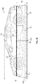
- FIGS. 1A and 1B illustrate a protective cover with a ground surface seal, according to alternative embodiments
- FIG. 1C illustrates a perspective view of the protective cover illustrated in FIG. 1B , according to an embodiment.
- the protective cover 100 comprises a protective top cover 110 and an apron 120.
- Protective top cover 110 may be made of a breathable, sun-reflective, and durable material.
- Apron 120 may be made of a water-proof or water-resistant material, which may be thicker than protective top cover 110, and which has a height H 2 .
- Protective top cover 110 and apron 120 may be made of the same material or different material.
- protective top cover 110 and apron 120 are illustrated as separate components of protective cover 100, in an alternative embodiment, protective top cover 110 and apron 120 may be manufactured as a single piece of material.
- apron 120 is sealed or fixed (e.g., sewn) to protective cover at connection 122 without any gaps.
- apron 120 is detachably fixed to protective cover (e.g., by a zipper between the edge of protective top cover 110 and apron 120) at connection 122 without any gaps.
- detachable apron 120 allows a user to separate apron 120 from protective top cover 110. This enables the user to take apron 120 with him or her.
- protective cover 100 is a vehicle cover
- detachable apron 120 enables a user to detach and leave apron 120 on the ground (e.g., with sealing tube 130 remaining in a substantially rectangular shape, representing the outline of the vehicle) and drive into or out of apron 120.
- the user only needs to place apron 120 once (e.g., in his or her garage, car port, or other parking space), and does not have to move it (or may only move it infrequently) for all subsequent uses.
- the user no longer has to lift apron 120 (which may be heavy due to sealing tube 130) over vehicle 10 for each use.
- a user may detach the top edge of apron 120 from the bottom edge of protective top cover 110 (e.g., by unzipping connection 122). Gravity will force apron 120 to collapse (e.g., crumple or fold) to the ground, but apron 120 will remain in its current outline (e.g., despite rain or other external influences), around vehicle 10, due to the weight of sealing tube 130.
- the user may remove protective top cover 110 from vehicle 10 and set it aside (e.g., by folding protective top cover 110 and/or placing protective top cover 110 within a storage space of a garage, vehicle 10, etc.).
- the user could take protective top cover 110 with him or her (e.g., place it in a storage compartment of vehicle 10, such as the trunk), and use it elsewhere (e.g., in a public parking space) without apron 120 or with a different apron 120 (e.g., previously placed in another private parking space).
- the user may drive vehicle 10 out from the surrounding apron 120 by simply driving over one side of apron 120 (i.e., the side in front of or behind vehicle 10).
- the user may again drive over one side of apron 120 to once again position vehicle 10 within the center of apron 120.
- the user may then place protective top cover 110 over vehicle 10, and pull up and reattach the top edge of apron 120 to the bottom edge of protective cover 110 (e.g., by zipping connection 122), to once again protect vehicle 10 with protective cover 100 having a ground seal formed by sealing tube 130.
- apron 120 may comprise an apron extension 126, which extends from connection 122 towards the ground with a height H 3 .
- H 3 is at least 30 centimetres (twelve inches) .
- the combined height of apron extension 126 (i.e., H 3 ) and sealing tube 130 (e.g., H 4 ) may be of a sufficient height to make it easy for the user to detach (e.g., unzip) apron 120 without having to uncomfortably bend over or lift sealing tube 130.
- conformance to the ground surface, in a resting state of apron 120 may be achieved by a sealing tube 130, which may be filled with a surface contouring material 134.
- Sealing tube 130 may be sealed or fixed (e.g., sewn) to apron extension 126 to prevent any gaps within apron 120.
- Contouring material 134 may be a dry material, such as dry, powdered sand or a material with similar characteristics. Alternatively, a wet material, such as water, may be used.
- sealing tube 130 may comprise or be formed as an envelope that contains contouring material 134.
- the envelope may be at least five centimetres (two inches) wide to ensure that sealing tube 130 is of sufficient size and weight to conform to the ground surface.
- the envelope may have a substantially cylindrical shape with a diameter of five centimetres (two inches) or more. However, a width or diameter of less than five centimetres (two inches) may be used (e.g., if the envelope is filled with a heavier contouring material 134).
- the type and amount of contouring material 134 and the size of the envelope in sealing tube 130 should be selected to gravitationally seal apron 120 to the ground surface with sufficient weight, so as to prevent or restrict rodents and/or insects from passing underneath sealing tube 130, without compromising the conformance of sealing tube 130 to the ground. If sealing tube 130 is overfilled (e.g., too much sand is used to fill the envelope), sealing tube 130 may not properly conform to the ground. On the other hand, if sealing tube 130 is under-filled (e.g., too little sand is used to fill the envelope), sealing tube 130 may not be heavy enough to seal to the ground.
- sealing tube 130 may not be heavy enough to restrict the ingress of rodents or insects.
- a proper amount of contouring material 134 will allow the particles to flow in sealing tube 130, so as to be evenly distributed along the entire length of sealing tube 130.
- FIG 4A represents a top-down or bottom-up view of apron 120, according to an embodiment.
- apron 120 e.g., one or more of connection 122, apron extension 126, and sealing tube 130
- segment 132 may be bent, and then the two ends of segment 132 may be fixed to each other to form segment 132 into an apron 120 capable of surrounding an object.
- segment only refers to the outline of apron 120, and that a single segment may comprise numerous different materials and/or components (e.g., a connection 122, apron extension 126, and/or sealing tube 130 stitched together or otherwise affixed to each other).
- the ends of segment 132 may overlap in overlap region 136 to create a firm seal.
- Overlap region 136 has a length of L.
- L is 7.6 centimetres (3 inches) or more.
- the ends of segment 132 may be fixed to each other by any conventional means, including, without limitation, adhesive, stitching, Velcro TM , and/or the like.
- FIG 4B represents a top-down or bottom-up view of apron 120, according to an alternative embodiment.
- apron 120 e.g., one or more of connection 122, apron extension 126, and sealing tube 130
- segments 132A-132D are illustrated, it should be understood that any number of segments 132 may be used.
- improper segmentation can lead to gaps between sealing tube 130 and the ground, which compromises the protective qualities of the ground seal.
- each segment 132 may overlap each adjacent segment 132 in overlap regions 136 to create a firm seal.
- each overlap region 136 has a length of L, which, in an embodiment, is 7.6 centimetres (3 inches) or more.
- the ends of segments 136 e.g., the end of segment 132A and segment 132B in overlap region 136B) may be fixed to each other by any conventional means.
- protective top cover 110 may comprise fasteners (e.g., Velcro TM or other types of straps) that can be used to remove slack in protective top cover 110, and keep protective top cover 110 from touching the ground surface. This ensures that only apron 120 (e.g., which may be made of water-proof or water-resistant material) is in contact with the ground surface.
- fasteners e.g., Velcro TM or other types of straps
Landscapes
- Engineering & Computer Science (AREA)
- Mechanical Engineering (AREA)
- Protection Of Pipes Against Damage, Friction, And Corrosion (AREA)
- Tents Or Canopies (AREA)
Description
- The embodiments described herein are generally directed to a protective cover, and, more particularly, to a protective cover with a ground surface seal for protecting an object (e.g., vehicle, furniture, etc.) from intrusion by external influences, such as rodents, insects, weather (e.g., wind, rain, snow, etc.), and the like.
- Conventional protective covers do not provide any seal at the ground surface. Unfortunately, this allows intrusion by external influences, which can damage the object being covered. External influences may include, without limitation, rodents, insects, wind, rain, snow, and/or other weather, and/or any other influence that can penetrate a gap or loose fit between an edge of the protective cover and the ground. Thus, what is needed is a protective cover with a ground surface seal to protect the object from such influences.
CN 203 832 216 U discloses the preamble ofclaim 1. - Accordingly, a protective cover with a ground surface seal is disclosed. In an embodiment, the protective cover comprises: a protective top cover comprising one or more edges; and an apron extending from the one or more edges of the protective top cover, wherein an edge of the apron, opposite the one or more edges of the protective top cover, comprises a sealing tube that contains a compressible, contouring material, so as to form a seal between the edge of the apron and a ground surface when the protective cover is deployed. The apron may be detachable from the one or more edges of the protective top cover. For example, the apron may be attached to the one or more edges of the protective top cover by a zipper.
- In an embodiment, the apron is at least 30 centimetres (12 inches) wide between the one or more edges of the protective top cover and the sealing tube. The apron may comprise a single segment whose ends are fixed to each other at an overlap region. Alternatively, the apron may comprise a plurality of segments, wherein each end of each segment overlaps with an adjacent end of an adjacent segment at an overlap region. In either case, the overlap region may be at least 7.6 centimetres (3 inches) wide.
- In an embodiment, each end may be attachable and detachable to another end (e.g., the opposite end if the apron is embodied as a single segment, or adjacent ends if the apron is embodied as a plurality of segments) by a first fastener. The first fastener may comprise Velcro™. Alternatively, each end may be permanently fixed to the overlapping end (e.g., by adhesive, stitching, and/or the like).
- In an embodiment, at least one end of the sealing tube of each segment (e.g., whether a single segment or a plurality of segments are used) may comprise a second fastener to close the at least one end of the sealing tube, so as to seal the contouring material within the sealing tube, and open the at least one end of the sealing tube, so as to provide access to the contouring material within the sealing tube. The second fastener may comprise Velcro™. Alternatively, the sealing tube may be permanently closed with the contouring material inside. In either case, the contouring material may comprise sand. In addition, the sealing tube may be substantially cylindrical, and the substantially cylindrical sealing tube may have a diameter or width of at least 5 centimetres (two inches)
- In an embodiment, the protective cover is configured to cover a vehicle. Alternatively, the protective cover is configured to cover furniture.
- The details of the present invention, both as to its structure and operation, may be gleaned in part by study of the accompanying drawings, in which like reference numerals refer to like parts, and in which:
-
FIGS. 1A and1B illustrate a protective cover, according to alternative embodiments; -
FIG. 1C illustrates a perspective view of a protective cover, according to an embodiment; -
FIG. 2 illustrates an apron of a protective cover, according to an embodiment; -
FIG. 3 illustrates a sealing tube of an apron of a protective cover, according to an embodiment; -
FIGS. 4A-4C illustrates segmentation of an apron of a protective cover, according to embodiments; -
FIG. 5 illustrates fastening between segments of an apron of a protective cover, according to an embodiment; and -
FIG. 6 illustrates fastening of an end of a sealing tube of a segment of an apron of a protective cover, according to an embodiment. - In an embodiment, a protective cover with a ground surface seal is disclosed. The protective cover may be used indoors or outdoors to store, cover, and protect objects (e.g., vehicles, furniture, etc.) from weather (e.g., wind, rain, snow, etc.), occupation or damage by rodents or insects, and/or the like. The cover may either loosely conform to the object (e.g., generic cover, such as for furniture) or tightly conform to the object (e.g., custom cover, such as a custom vehicle cover, for example, shaped for a particular vehicle). While the cover will be primarily described and illustrated herein as a vehicle cover, it should be understood that the cover may be sized and adapted to cover any object, including, without limitation, indoor and/or outdoor furniture (e.g., chairs, tables, grills, dressers, shelves, etc.).
- After reading this description, it will become apparent to one skilled in the art how to implement the invention in various alternative embodiments and alternative applications. However, although various embodiments of the present invention will be described herein, it is understood that these embodiments are presented by way of example and illustration only, and not limitation. As such, this detailed description of various embodiments should not be construed to limit the scope or breadth of the present invention as set forth in the appended claims.
-
FIGS. 1A and1B illustrate a protective cover with a ground surface seal, according to alternative embodiments, andFIG. 1C illustrates a perspective view of the protective cover illustrated inFIG. 1B , according to an embodiment. As illustrated, in both embodiments, theprotective cover 100 comprises aprotective top cover 110 and anapron 120. Protectivetop cover 110 may be made of a breathable, sun-reflective, and durable material. Apron 120 may be made of a water-proof or water-resistant material, which may be thicker than protectivetop cover 110, and which has a height H2. Protectivetop cover 110 andapron 120 may be made of the same material or different material. Furthermore, whileprotective top cover 110 andapron 120 are illustrated as separate components ofprotective cover 100, in an alternative embodiment,protective top cover 110 andapron 120 may be manufactured as a single piece of material. - In order to highlight its height and features,
apron 120 is illustrated inFIGS. 1A and1B as extending below the ground. However, it should be understood that, in an actual implementation, depending on height H1,apron 120 would either extend exactly flush with the ground (e.g., if H1 is exactly the height ofvehicle 10, i.e., from the bottom of its tires to the top of its roof) or, in a preferred embodiment, extend at least slightly beyond the bottom of the vehicle (e.g., if H1 is greater than the height of vehicle 10) so that it bends outward or inward, or crumples or folds, to lie flush with the ground. Whileapron 120 could be sized so that it hangs above the ground (e.g., if H1 is less than the height of vehicle 10), it should be understood that this would not be preferred if the objective is to provide a ground seal. - In the embodiment illustrated in
FIG. 1A ,apron 120 is sealed or fixed (e.g., sewn) to protective cover atconnection 122 without any gaps. In the alternative embodiment illustrated inFIG. 1B ,apron 120 is detachably fixed to protective cover (e.g., by a zipper between the edge ofprotective top cover 110 and apron 120) atconnection 122 without any gaps. - Advantageously,
detachable apron 120, illustrated inFIG. 1B , allows a user to separateapron 120 fromprotective top cover 110. This enables the user to takeapron 120 with him or her. In addition, ifprotective cover 100 is a vehicle cover,detachable apron 120 enables a user to detach and leaveapron 120 on the ground (e.g., with sealingtube 130 remaining in a substantially rectangular shape, representing the outline of the vehicle) and drive into or out ofapron 120. In other words, the user only needs to placeapron 120 once (e.g., in his or her garage, car port, or other parking space), and does not have to move it (or may only move it infrequently) for all subsequent uses. Furthermore, the user no longer has to lift apron 120 (which may be heavy due to sealing tube 130) overvehicle 10 for each use. - Specifically, when exiting a parking space, a user may detach the top edge of
apron 120 from the bottom edge of protective top cover 110 (e.g., by unzipping connection 122). Gravity will forceapron 120 to collapse (e.g., crumple or fold) to the ground, butapron 120 will remain in its current outline (e.g., despite rain or other external influences), aroundvehicle 10, due to the weight of sealingtube 130. The user may remove protectivetop cover 110 fromvehicle 10 and set it aside (e.g., by folding protectivetop cover 110 and/or placing protectivetop cover 110 within a storage space of a garage,vehicle 10, etc.). In some instances, the user could take protectivetop cover 110 with him or her (e.g., place it in a storage compartment ofvehicle 10, such as the trunk), and use it elsewhere (e.g., in a public parking space) withoutapron 120 or with a different apron 120 (e.g., previously placed in another private parking space). The user may drivevehicle 10 out from the surroundingapron 120 by simply driving over one side of apron 120 (i.e., the side in front of or behind vehicle 10). When the user returns to the parking space, the user may again drive over one side ofapron 120 to once again positionvehicle 10 within the center ofapron 120. The user may then place protectivetop cover 110 overvehicle 10, and pull up and reattach the top edge ofapron 120 to the bottom edge of protective cover 110 (e.g., by zipping connection 122), to once again protectvehicle 10 withprotective cover 100 having a ground seal formed by sealingtube 130. - As illustrated in a cut-out view in
FIG. 2 ,apron 120 may comprise anapron extension 126, which extends fromconnection 122 towards the ground with a height H3. In a preferred embodiment, H3 is at least 30 centimetres (twelve inches) . In the embodiment illustrated inFIG 1B , with adetachable apron 120, the combined height of apron extension 126 (i.e., H3) and sealing tube 130 (e.g., H4) may be of a sufficient height to make it easy for the user to detach (e.g., unzip)apron 120 without having to uncomfortably bend over orlift sealing tube 130. For example, the total height of apron 120 (i.e., H2=H3+H4) may be equal to or greater than 45 centimetres (eighteen inches) - As illustrated in
FIG. 3 , conformance to the ground surface, in a resting state ofapron 120, may be achieved by a sealingtube 130, which may be filled with asurface contouring material 134.Sealing tube 130 may be sealed or fixed (e.g., sewn) toapron extension 126 to prevent any gaps withinapron 120.Contouring material 134 may be a dry material, such as dry, powdered sand or a material with similar characteristics. Alternatively, a wet material, such as water, may be used. - In an embodiment, sealing
tube 130 may comprise or be formed as an envelope that contains contouringmaterial 134. The envelope may be at least five centimetres (two inches) wide to ensure that sealingtube 130 is of sufficient size and weight to conform to the ground surface. For example, the envelope may have a substantially cylindrical shape with a diameter of five centimetres (two inches) or more. However, a width or diameter of less than five centimetres (two inches) may be used (e.g., if the envelope is filled with a heavier contouring material 134). - The type and amount of contouring
material 134 and the size of the envelope in sealingtube 130 should be selected to gravitationally sealapron 120 to the ground surface with sufficient weight, so as to prevent or restrict rodents and/or insects from passing underneath sealingtube 130, without compromising the conformance of sealingtube 130 to the ground. If sealingtube 130 is overfilled (e.g., too much sand is used to fill the envelope), sealingtube 130 may not properly conform to the ground. On the other hand, if sealingtube 130 is under-filled (e.g., too little sand is used to fill the envelope), sealingtube 130 may not be heavy enough to seal to the ground. In other words, gaps may form between sealingtube 130 and the ground, or sealingtube 130 may not be heavy enough to restrict the ingress of rodents or insects. A proper amount of contouringmaterial 134 will allow the particles to flow in sealingtube 130, so as to be evenly distributed along the entire length of sealingtube 130. -
FIG 4A represents a top-down or bottom-up view ofapron 120, according to an embodiment. As illustrated inFIG. 4A , in an embodiment, apron 120 (e.g., one or more ofconnection 122,apron extension 126, and sealing tube 130) may be manufactured as a singlelinear segment 132.Segment 132 may be bent, and then the two ends ofsegment 132 may be fixed to each other to formsegment 132 into anapron 120 capable of surrounding an object. It should be understood that, as used herein, the term "segment" only refers to the outline ofapron 120, and that a single segment may comprise numerous different materials and/or components (e.g., aconnection 122,apron extension 126, and/or sealingtube 130 stitched together or otherwise affixed to each other). - As illustrated in more detail in
FIG. 4C , the ends ofsegment 132 may overlap inoverlap region 136 to create a firm seal. Overlapregion 136 has a length of L. In an embodiment, L is 7.6 centimetres (3 inches) or more. . The ends ofsegment 132 may be fixed to each other by any conventional means, including, without limitation, adhesive, stitching, Velcro™, and/or the like. -
FIG 4B represents a top-down or bottom-up view ofapron 120, according to an alternative embodiment. As illustrated inFIG. 4B , in the alternative embodiment, apron 120 (e.g., one or more ofconnection 122,apron extension 126, and sealing tube 130) is segmented into a plurality ofsegments 132. This enables a user to easily foldprotective cover 100 orapron 120 for storage or transportation. While foursegments 132A-132D are illustrated, it should be understood that any number ofsegments 132 may be used. However, improper segmentation can lead to gaps between sealingtube 130 and the ground, which compromises the protective qualities of the ground seal. Thus, as illustrated in more detail inFIG. 4C , eachsegment 132 may overlap eachadjacent segment 132 inoverlap regions 136 to create a firm seal. Again, each overlapregion 136 has a length of L, which, in an embodiment, is 7.6 centimetres (3 inches) or more. . The ends of segments 136 (e.g., the end ofsegment 132A andsegment 132B inoverlap region 136B) may be fixed to each other by any conventional means. -
FIG. 5 illustrates attachable and detachable segments ends which may be used in one ormore overlap regions 136, according to an embodiment. As illustrated, afastener 138 may be used at eachoverlap region 136 to ensure that the ends of segment(s) 132 remain detachably sealed together at theirrespective overlap region 136, so as not to compromise the seal between sealingtube 130 and the ground surface and so as not to separate from each other. In the illustrated embodiment, fastener comprises corresponding Velcro™ strips, for example, with a hook strip on the end of onesegment 132A and a loop strip on the end of anadjacent segment 132B. However, it should be understood that other types of fasteners are possible. -
FIG. 6 illustrates a cut-away view of the end of asegment 132 of sealingtube 130, according to an embodiment. As illustrated, afastener 140 may be used at one or both ends of eachsegment 132 to retaincontouring material 134 within the envelope, formed byfabric 142, of eachsegment 132. This enables contouringmaterial 134 in sealingtube 130 to be driven over or otherwise compressed (e.g., accidentally or on purpose), while still enablingcontouring material 134 to be removed from sealingtube 130 for easier storage or transportation (e.g., shipping). In an embodiment,fastener 140 may comprise corresponding Velcro™ strips, for example, with a hook strip on one surface of the end ofsegment 132 and a loop strip on an adjacent surface of the end ofsegment 132. Alternatively, the ends of eachsegment 132 may be sealed, so as to permanently sealcontouring material 134 within the sealing tube of eachsegment 132. - In the case of a generic protective cover - as opposed to a custom-fitted protective cover - protective
top cover 110 may comprise fasteners (e.g., Velcro™ or other types of straps) that can be used to remove slack in protectivetop cover 110, and keep protectivetop cover 110 from touching the ground surface. This ensures that only apron 120 (e.g., which may be made of water-proof or water-resistant material) is in contact with the ground surface. - The above description of the disclosed embodiments is provided to enable any person skilled in the art to make or use the invention. Various modifications to these embodiments will be readily apparent to those skilled in the art, and the general principles described herein can be applied to other embodiments without departing from the spirit or scope of the invention as disclosed by the claims. Thus, it is to be understood that the description and drawings presented herein represent a presently preferred embodiment of the invention and are therefore representative of the subject matter which is broadly contemplated by the present invention.
Claims (13)
- A protective cover (100) comprising:a protective top cover (110) comprising one or more edges; andan apron (120) extending from the one or more edges of the protective top cover, wherein an edge of the apron, opposite the one or more edges of the protective top cover, characterised in that the protective top further comprises a sealing tube (130) that contains a compressible, contouring material, so as to form a seal between the edge of the apron and a ground surface when the protective cover is deployedwherein the apron comprises a plurality of segments (132)wherein each end of each segment overlaps with an adjacent end of an adjacent segment at an overlap region, andwherein each end is attachable and detachable to its overlapping end by a first fastener (138).
- The protective cover of Claim 1, wherein the apron is detachable from the one or more edges of the protective top cover.
- The protective cover of Claim 2, wherein the apron is attached to the one or more edges of the protective top cover by a zipper (122).
- The protective cover of Claim 1, wherein the apron is at least 30 centimetres (twelve inches) wide between the one or more edges of the protective top cover and the sealing tube.
- The protective cover of Claim 1, wherein the overlap region is at least 7.6 centimetres (three inches) wide.
- The protective cover of Claim 1, wherein the first fastener comprises Hook- and-loop fasteners.
- The protective cover of any preceding claim, wherein at least one end of the sealing tube of each segment comprises a second fastener (140) to close the at least one end of the sealing tube, so as to seal the contouring material within the sealing tube, and open the at least one end of the sealing tube, so as to provide access to the contouring material within the sealing tube.
- The protective cover of Claim 7, wherein the second fastener comprises Hook- and-loop fasteners.
- The protective cover of Claim 1, wherein the contouring material comprises sand.
- The protective cover of Claim 1, wherein the protective cover is configured to cover a vehicle.
- The protective cover of Claim 1, wherein the protective cover is configured to cover furniture.
- The protective cover of Claim 1, wherein the sealing tube is substantially cylindrical.
- The protective cover of Claim 12, wherein the substantially cylindrically sealing tube has a diameter or width of at least five centimetres (two inches).
Applications Claiming Priority (2)
| Application Number | Priority Date | Filing Date | Title |
|---|---|---|---|
| US201762580870P | 2017-11-02 | 2017-11-02 | |
| PCT/US2018/055616 WO2019089209A1 (en) | 2017-11-02 | 2018-10-12 | Protective cover with ground surface seal |
Publications (3)
| Publication Number | Publication Date |
|---|---|
| EP3703938A1 EP3703938A1 (en) | 2020-09-09 |
| EP3703938A4 EP3703938A4 (en) | 2021-08-04 |
| EP3703938B1 true EP3703938B1 (en) | 2022-11-23 |
Family
ID=66332716
Family Applications (1)
| Application Number | Title | Priority Date | Filing Date |
|---|---|---|---|
| EP18872549.3A Active EP3703938B1 (en) | 2017-11-02 | 2018-10-12 | Protective cover with ground surface seal |
Country Status (4)
| Country | Link |
|---|---|
| US (1) | US11491855B2 (en) |
| EP (1) | EP3703938B1 (en) |
| CN (1) | CN111491791B (en) |
| WO (1) | WO2019089209A1 (en) |
Families Citing this family (3)
| Publication number | Priority date | Publication date | Assignee | Title |
|---|---|---|---|---|
| CN115666922B (en) * | 2020-01-24 | 2026-04-03 | K·J·许宁 | Protective cover with ground seal |
| CN113386541A (en) * | 2021-07-19 | 2021-09-14 | 屈世强 | Protective equipment |
| US20230129774A1 (en) * | 2021-10-25 | 2023-04-27 | Christopher Joseph McEntee | Grill Cover Complement II |
Family Cites Families (12)
| Publication number | Priority date | Publication date | Assignee | Title |
|---|---|---|---|---|
| US2243981A (en) * | 1939-11-24 | 1941-06-03 | Rowan Bridge | Automobile cover |
| US2311514A (en) * | 1942-05-12 | 1943-02-16 | Bramblett Ora | Portable shelter for motor vehicles |
| US2994356A (en) * | 1960-04-22 | 1961-08-01 | Samuel W Fleming | Automobile protector |
| US3862876A (en) * | 1973-04-02 | 1975-01-28 | James E Graves | Protective edge weighted cover cloth |
| GB2038776B (en) * | 1979-01-04 | 1982-12-15 | Airflex Containers Ltd | Evacuable containers |
| US5497819A (en) * | 1993-10-18 | 1996-03-12 | Chiang; Hsi-Ming | Modular car cover |
| AU7720000A (en) | 1999-09-27 | 2001-04-30 | Jeremy Hoenack | Ballistically deployed vehicle and utility covers |
| US6485086B2 (en) * | 2001-02-06 | 2002-11-26 | Popcover, Inc. | Self-deploying vehicle cover with lock |
| CN104507341A (en) | 2012-07-31 | 2015-04-08 | W.L.戈尔有限公司 | Combination of envelope for laminar structure providing adaptive thermal insulation and heat protection shield |
| US20140042771A1 (en) | 2012-08-13 | 2014-02-13 | Wen Liang Lo | Waterproof Car Cover |
| CN203832216U (en) | 2014-05-22 | 2014-09-17 | 陈茂彪 | Anti-mouse anti-wind multifunctional automobile cover |
| FR3037288B1 (en) | 2015-06-12 | 2017-12-22 | Arthur Veis | INFLATABLE DEVICE FOR PROTECTING AN OBJECT, IN PARTICULAR AGAINST HAIL |
-
2018
- 2018-10-12 WO PCT/US2018/055616 patent/WO2019089209A1/en not_active Ceased
- 2018-10-12 CN CN201880081740.9A patent/CN111491791B/en active Active
- 2018-10-12 US US16/760,849 patent/US11491855B2/en active Active
- 2018-10-12 EP EP18872549.3A patent/EP3703938B1/en active Active
Also Published As
| Publication number | Publication date |
|---|---|
| CN111491791B (en) | 2022-04-22 |
| EP3703938A1 (en) | 2020-09-09 |
| US20210170850A1 (en) | 2021-06-10 |
| EP3703938A4 (en) | 2021-08-04 |
| US11491855B2 (en) | 2022-11-08 |
| CN111491791A (en) | 2020-08-04 |
| WO2019089209A1 (en) | 2019-05-09 |
Similar Documents
| Publication | Publication Date | Title |
|---|---|---|
| US6439637B1 (en) | Golf cart cover | |
| US10766345B2 (en) | Hail-resistant vehicle cover | |
| US6220647B1 (en) | Retractable awning for a golf cart | |
| EP3703938B1 (en) | Protective cover with ground surface seal | |
| US2911253A (en) | Automobile trunk liner | |
| US5217275A (en) | Golf cart cover | |
| US20120248817A1 (en) | Pop up quick camper | |
| US5310235A (en) | Golf cart weathershield | |
| US4283084A (en) | Motorcycle cover | |
| US2917094A (en) | Cover for shopping carts | |
| US20110095561A1 (en) | Folding roof cover for vehicles | |
| US6749250B1 (en) | Tailgate cover | |
| US20040207229A1 (en) | Soft golf cart shield | |
| US9688129B2 (en) | Vehicle windshield cover and method therefor | |
| US5010941A (en) | Golf cart drop curtain | |
| US20140054921A1 (en) | Portable golf cart cover | |
| US20140167444A1 (en) | Vehicle snow & ice removal system/cover | |
| US2907056A (en) | Sleeping-bag-tent construction | |
| US11970050B2 (en) | Protective cover with ground surface seal | |
| US7318392B2 (en) | Protective wrap around encasement for a pet carrier | |
| US20240229498A1 (en) | Aircraft tent apparatus | |
| US20160167498A1 (en) | Vehicle Cover | |
| US20120145208A1 (en) | Tarp with pliable frame | |
| US6141891A (en) | Snow plow cover | |
| US6941709B1 (en) | Door insulator |
Legal Events
| Date | Code | Title | Description |
|---|---|---|---|
| STAA | Information on the status of an ep patent application or granted ep patent |
Free format text: STATUS: THE INTERNATIONAL PUBLICATION HAS BEEN MADE |
|
| PUAI | Public reference made under article 153(3) epc to a published international application that has entered the european phase |
Free format text: ORIGINAL CODE: 0009012 |
|
| STAA | Information on the status of an ep patent application or granted ep patent |
Free format text: STATUS: REQUEST FOR EXAMINATION WAS MADE |
|
| 17P | Request for examination filed |
Effective date: 20200430 |
|
| AK | Designated contracting states |
Kind code of ref document: A1 Designated state(s): AL AT BE BG CH CY CZ DE DK EE ES FI FR GB GR HR HU IE IS IT LI LT LU LV MC MK MT NL NO PL PT RO RS SE SI SK SM TR |
|
| AX | Request for extension of the european patent |
Extension state: BA ME |
|
| DAV | Request for validation of the european patent (deleted) | ||
| DAX | Request for extension of the european patent (deleted) | ||
| A4 | Supplementary search report drawn up and despatched |
Effective date: 20210707 |
|
| RIC1 | Information provided on ipc code assigned before grant |
Ipc: B60J 11/04 20060101AFI20210701BHEP |
|
| REG | Reference to a national code |
Ref country code: DE Ref legal event code: R079 Ref document number: 602018043483 Country of ref document: DE Free format text: PREVIOUS MAIN CLASS: B32B0003040000 Ipc: B60J0011040000 |
|
| RIC1 | Information provided on ipc code assigned before grant |
Ipc: B60J 11/04 20060101AFI20220422BHEP |
|
| GRAP | Despatch of communication of intention to grant a patent |
Free format text: ORIGINAL CODE: EPIDOSNIGR1 |
|
| STAA | Information on the status of an ep patent application or granted ep patent |
Free format text: STATUS: GRANT OF PATENT IS INTENDED |
|
| INTG | Intention to grant announced |
Effective date: 20220607 |
|
| GRAS | Grant fee paid |
Free format text: ORIGINAL CODE: EPIDOSNIGR3 |
|
| GRAA | (expected) grant |
Free format text: ORIGINAL CODE: 0009210 |
|
| STAA | Information on the status of an ep patent application or granted ep patent |
Free format text: STATUS: THE PATENT HAS BEEN GRANTED |
|
| AK | Designated contracting states |
Kind code of ref document: B1 Designated state(s): AL AT BE BG CH CY CZ DE DK EE ES FI FR GB GR HR HU IE IS IT LI LT LU LV MC MK MT NL NO PL PT RO RS SE SI SK SM TR |
|
| REG | Reference to a national code |
Ref country code: GB Ref legal event code: FG4D |
|
| REG | Reference to a national code |
Ref country code: CH Ref legal event code: EP |
|
| REG | Reference to a national code |
Ref country code: DE Ref legal event code: R096 Ref document number: 602018043483 Country of ref document: DE |
|
| REG | Reference to a national code |
Ref country code: AT Ref legal event code: REF Ref document number: 1532927 Country of ref document: AT Kind code of ref document: T Effective date: 20221215 |
|
| REG | Reference to a national code |
Ref country code: IE Ref legal event code: FG4D |
|
| REG | Reference to a national code |
Ref country code: LT Ref legal event code: MG9D |
|
| REG | Reference to a national code |
Ref country code: NL Ref legal event code: MP Effective date: 20221123 |
|
| REG | Reference to a national code |
Ref country code: AT Ref legal event code: MK05 Ref document number: 1532927 Country of ref document: AT Kind code of ref document: T Effective date: 20221123 |
|
| PG25 | Lapsed in a contracting state [announced via postgrant information from national office to epo] |
Ref country code: SE Free format text: LAPSE BECAUSE OF FAILURE TO SUBMIT A TRANSLATION OF THE DESCRIPTION OR TO PAY THE FEE WITHIN THE PRESCRIBED TIME-LIMIT Effective date: 20221123 Ref country code: PT Free format text: LAPSE BECAUSE OF FAILURE TO SUBMIT A TRANSLATION OF THE DESCRIPTION OR TO PAY THE FEE WITHIN THE PRESCRIBED TIME-LIMIT Effective date: 20230323 Ref country code: NO Free format text: LAPSE BECAUSE OF FAILURE TO SUBMIT A TRANSLATION OF THE DESCRIPTION OR TO PAY THE FEE WITHIN THE PRESCRIBED TIME-LIMIT Effective date: 20230223 Ref country code: LT Free format text: LAPSE BECAUSE OF FAILURE TO SUBMIT A TRANSLATION OF THE DESCRIPTION OR TO PAY THE FEE WITHIN THE PRESCRIBED TIME-LIMIT Effective date: 20221123 Ref country code: FI Free format text: LAPSE BECAUSE OF FAILURE TO SUBMIT A TRANSLATION OF THE DESCRIPTION OR TO PAY THE FEE WITHIN THE PRESCRIBED TIME-LIMIT Effective date: 20221123 Ref country code: ES Free format text: LAPSE BECAUSE OF FAILURE TO SUBMIT A TRANSLATION OF THE DESCRIPTION OR TO PAY THE FEE WITHIN THE PRESCRIBED TIME-LIMIT Effective date: 20221123 Ref country code: AT Free format text: LAPSE BECAUSE OF FAILURE TO SUBMIT A TRANSLATION OF THE DESCRIPTION OR TO PAY THE FEE WITHIN THE PRESCRIBED TIME-LIMIT Effective date: 20221123 |
|
| PG25 | Lapsed in a contracting state [announced via postgrant information from national office to epo] |
Ref country code: RS Free format text: LAPSE BECAUSE OF FAILURE TO SUBMIT A TRANSLATION OF THE DESCRIPTION OR TO PAY THE FEE WITHIN THE PRESCRIBED TIME-LIMIT Effective date: 20221123 Ref country code: PL Free format text: LAPSE BECAUSE OF FAILURE TO SUBMIT A TRANSLATION OF THE DESCRIPTION OR TO PAY THE FEE WITHIN THE PRESCRIBED TIME-LIMIT Effective date: 20221123 Ref country code: LV Free format text: LAPSE BECAUSE OF FAILURE TO SUBMIT A TRANSLATION OF THE DESCRIPTION OR TO PAY THE FEE WITHIN THE PRESCRIBED TIME-LIMIT Effective date: 20221123 Ref country code: IS Free format text: LAPSE BECAUSE OF FAILURE TO SUBMIT A TRANSLATION OF THE DESCRIPTION OR TO PAY THE FEE WITHIN THE PRESCRIBED TIME-LIMIT Effective date: 20230323 Ref country code: HR Free format text: LAPSE BECAUSE OF FAILURE TO SUBMIT A TRANSLATION OF THE DESCRIPTION OR TO PAY THE FEE WITHIN THE PRESCRIBED TIME-LIMIT Effective date: 20221123 Ref country code: GR Free format text: LAPSE BECAUSE OF FAILURE TO SUBMIT A TRANSLATION OF THE DESCRIPTION OR TO PAY THE FEE WITHIN THE PRESCRIBED TIME-LIMIT Effective date: 20230224 |
|
| PG25 | Lapsed in a contracting state [announced via postgrant information from national office to epo] |
Ref country code: NL Free format text: LAPSE BECAUSE OF FAILURE TO SUBMIT A TRANSLATION OF THE DESCRIPTION OR TO PAY THE FEE WITHIN THE PRESCRIBED TIME-LIMIT Effective date: 20221123 |
|
| PG25 | Lapsed in a contracting state [announced via postgrant information from national office to epo] |
Ref country code: SM Free format text: LAPSE BECAUSE OF FAILURE TO SUBMIT A TRANSLATION OF THE DESCRIPTION OR TO PAY THE FEE WITHIN THE PRESCRIBED TIME-LIMIT Effective date: 20221123 Ref country code: RO Free format text: LAPSE BECAUSE OF FAILURE TO SUBMIT A TRANSLATION OF THE DESCRIPTION OR TO PAY THE FEE WITHIN THE PRESCRIBED TIME-LIMIT Effective date: 20221123 Ref country code: EE Free format text: LAPSE BECAUSE OF FAILURE TO SUBMIT A TRANSLATION OF THE DESCRIPTION OR TO PAY THE FEE WITHIN THE PRESCRIBED TIME-LIMIT Effective date: 20221123 Ref country code: DK Free format text: LAPSE BECAUSE OF FAILURE TO SUBMIT A TRANSLATION OF THE DESCRIPTION OR TO PAY THE FEE WITHIN THE PRESCRIBED TIME-LIMIT Effective date: 20221123 Ref country code: CZ Free format text: LAPSE BECAUSE OF FAILURE TO SUBMIT A TRANSLATION OF THE DESCRIPTION OR TO PAY THE FEE WITHIN THE PRESCRIBED TIME-LIMIT Effective date: 20221123 |
|
| REG | Reference to a national code |
Ref country code: DE Ref legal event code: R097 Ref document number: 602018043483 Country of ref document: DE |
|
| PG25 | Lapsed in a contracting state [announced via postgrant information from national office to epo] |
Ref country code: SK Free format text: LAPSE BECAUSE OF FAILURE TO SUBMIT A TRANSLATION OF THE DESCRIPTION OR TO PAY THE FEE WITHIN THE PRESCRIBED TIME-LIMIT Effective date: 20221123 Ref country code: AL Free format text: LAPSE BECAUSE OF FAILURE TO SUBMIT A TRANSLATION OF THE DESCRIPTION OR TO PAY THE FEE WITHIN THE PRESCRIBED TIME-LIMIT Effective date: 20221123 |
|
| PLBE | No opposition filed within time limit |
Free format text: ORIGINAL CODE: 0009261 |
|
| STAA | Information on the status of an ep patent application or granted ep patent |
Free format text: STATUS: NO OPPOSITION FILED WITHIN TIME LIMIT |
|
| 26N | No opposition filed |
Effective date: 20230824 |
|
| P01 | Opt-out of the competence of the unified patent court (upc) registered |
Effective date: 20231004 |
|
| PG25 | Lapsed in a contracting state [announced via postgrant information from national office to epo] |
Ref country code: SI Free format text: LAPSE BECAUSE OF FAILURE TO SUBMIT A TRANSLATION OF THE DESCRIPTION OR TO PAY THE FEE WITHIN THE PRESCRIBED TIME-LIMIT Effective date: 20221123 |
|
| PG25 | Lapsed in a contracting state [announced via postgrant information from national office to epo] |
Ref country code: MC Free format text: LAPSE BECAUSE OF FAILURE TO SUBMIT A TRANSLATION OF THE DESCRIPTION OR TO PAY THE FEE WITHIN THE PRESCRIBED TIME-LIMIT Effective date: 20221123 |
|
| REG | Reference to a national code |
Ref country code: CH Ref legal event code: PL |
|
| REG | Reference to a national code |
Ref country code: BE Ref legal event code: MM Effective date: 20231031 |
|
| PG25 | Lapsed in a contracting state [announced via postgrant information from national office to epo] |
Ref country code: LU Free format text: LAPSE BECAUSE OF NON-PAYMENT OF DUE FEES Effective date: 20231012 |
|
| PG25 | Lapsed in a contracting state [announced via postgrant information from national office to epo] |
Ref country code: LU Free format text: LAPSE BECAUSE OF NON-PAYMENT OF DUE FEES Effective date: 20231012 |
|
| PG25 | Lapsed in a contracting state [announced via postgrant information from national office to epo] |
Ref country code: CH Free format text: LAPSE BECAUSE OF NON-PAYMENT OF DUE FEES Effective date: 20231031 |
|
| PG25 | Lapsed in a contracting state [announced via postgrant information from national office to epo] |
Ref country code: CH Free format text: LAPSE BECAUSE OF NON-PAYMENT OF DUE FEES Effective date: 20231031 |
|
| PG25 | Lapsed in a contracting state [announced via postgrant information from national office to epo] |
Ref country code: BE Free format text: LAPSE BECAUSE OF NON-PAYMENT OF DUE FEES Effective date: 20231031 |
|
| PG25 | Lapsed in a contracting state [announced via postgrant information from national office to epo] |
Ref country code: IE Free format text: LAPSE BECAUSE OF NON-PAYMENT OF DUE FEES Effective date: 20231012 |
|
| PG25 | Lapsed in a contracting state [announced via postgrant information from national office to epo] |
Ref country code: IE Free format text: LAPSE BECAUSE OF NON-PAYMENT OF DUE FEES Effective date: 20231012 |
|
| PG25 | Lapsed in a contracting state [announced via postgrant information from national office to epo] |
Ref country code: BG Free format text: LAPSE BECAUSE OF FAILURE TO SUBMIT A TRANSLATION OF THE DESCRIPTION OR TO PAY THE FEE WITHIN THE PRESCRIBED TIME-LIMIT Effective date: 20221123 |
|
| PG25 | Lapsed in a contracting state [announced via postgrant information from national office to epo] |
Ref country code: BG Free format text: LAPSE BECAUSE OF FAILURE TO SUBMIT A TRANSLATION OF THE DESCRIPTION OR TO PAY THE FEE WITHIN THE PRESCRIBED TIME-LIMIT Effective date: 20221123 |
|
| PG25 | Lapsed in a contracting state [announced via postgrant information from national office to epo] |
Ref country code: CY Free format text: LAPSE BECAUSE OF FAILURE TO SUBMIT A TRANSLATION OF THE DESCRIPTION OR TO PAY THE FEE WITHIN THE PRESCRIBED TIME-LIMIT; INVALID AB INITIO Effective date: 20181012 |
|
| PG25 | Lapsed in a contracting state [announced via postgrant information from national office to epo] |
Ref country code: HU Free format text: LAPSE BECAUSE OF FAILURE TO SUBMIT A TRANSLATION OF THE DESCRIPTION OR TO PAY THE FEE WITHIN THE PRESCRIBED TIME-LIMIT; INVALID AB INITIO Effective date: 20181012 |
|
| PGFP | Annual fee paid to national office [announced via postgrant information from national office to epo] |
Ref country code: IT Payment date: 20250922 Year of fee payment: 8 |
|
| PGFP | Annual fee paid to national office [announced via postgrant information from national office to epo] |
Ref country code: GB Payment date: 20250828 Year of fee payment: 8 |
|
| PGFP | Annual fee paid to national office [announced via postgrant information from national office to epo] |
Ref country code: FR Payment date: 20250908 Year of fee payment: 8 |
|
| PG25 | Lapsed in a contracting state [announced via postgrant information from national office to epo] |
Ref country code: TR Free format text: LAPSE BECAUSE OF FAILURE TO SUBMIT A TRANSLATION OF THE DESCRIPTION OR TO PAY THE FEE WITHIN THE PRESCRIBED TIME-LIMIT Effective date: 20221123 |
|
| PGFP | Annual fee paid to national office [announced via postgrant information from national office to epo] |
Ref country code: DE Payment date: 20250902 Year of fee payment: 8 |