EP3703644B1 - Filling machine - Google Patents
Filling machine Download PDFInfo
- Publication number
- EP3703644B1 EP3703644B1 EP18812253.5A EP18812253A EP3703644B1 EP 3703644 B1 EP3703644 B1 EP 3703644B1 EP 18812253 A EP18812253 A EP 18812253A EP 3703644 B1 EP3703644 B1 EP 3703644B1
- Authority
- EP
- European Patent Office
- Prior art keywords
- weighing
- capsules
- filling machine
- station
- filling
- Prior art date
- Legal status (The legal status is an assumption and is not a legal conclusion. Google has not performed a legal analysis and makes no representation as to the accuracy of the status listed.)
- Active
Links
Images


Classifications
-
- A—HUMAN NECESSITIES
- A61—MEDICAL OR VETERINARY SCIENCE; HYGIENE
- A61J—CONTAINERS SPECIALLY ADAPTED FOR MEDICAL OR PHARMACEUTICAL PURPOSES; DEVICES OR METHODS SPECIALLY ADAPTED FOR BRINGING PHARMACEUTICAL PRODUCTS INTO PARTICULAR PHYSICAL OR ADMINISTERING FORMS; DEVICES FOR ADMINISTERING FOOD OR MEDICINES ORALLY; BABY COMFORTERS; DEVICES FOR RECEIVING SPITTLE
- A61J3/00—Devices or methods specially adapted for bringing pharmaceutical products into particular physical or administering forms
- A61J3/07—Devices or methods specially adapted for bringing pharmaceutical products into particular physical or administering forms into the form of capsules or similar small containers for oral use
- A61J3/071—Devices or methods specially adapted for bringing pharmaceutical products into particular physical or administering forms into the form of capsules or similar small containers for oral use into the form of telescopically engaged two-piece capsules
- A61J3/074—Filling capsules; Related operations
-
- A—HUMAN NECESSITIES
- A61—MEDICAL OR VETERINARY SCIENCE; HYGIENE
- A61K—PREPARATIONS FOR MEDICAL, DENTAL OR TOILETRY PURPOSES
- A61K9/00—Medicinal preparations characterised by special physical form
- A61K9/48—Preparations in capsules, e.g. of gelatin, of chocolate
-
- B—PERFORMING OPERATIONS; TRANSPORTING
- B65—CONVEYING; PACKING; STORING; HANDLING THIN OR FILAMENTARY MATERIAL
- B65B—MACHINES, APPARATUS OR DEVICES FOR, OR METHODS OF, PACKAGING ARTICLES OR MATERIALS; UNPACKING
- B65B1/00—Packaging fluent solid material, e.g. powders, granular or loose fibrous material, loose masses of small articles, in individual containers or receptacles, e.g. bags, sacks, boxes, cartons, cans, or jars
- B65B1/04—Methods of, or means for, filling the material into the containers or receptacles
- B65B1/06—Methods of, or means for, filling the material into the containers or receptacles by gravity flow
-
- B—PERFORMING OPERATIONS; TRANSPORTING
- B65—CONVEYING; PACKING; STORING; HANDLING THIN OR FILAMENTARY MATERIAL
- B65B—MACHINES, APPARATUS OR DEVICES FOR, OR METHODS OF, PACKAGING ARTICLES OR MATERIALS; UNPACKING
- B65B1/00—Packaging fluent solid material, e.g. powders, granular or loose fibrous material, loose masses of small articles, in individual containers or receptacles, e.g. bags, sacks, boxes, cartons, cans, or jars
- B65B1/30—Devices or methods for controlling or determining the quantity or quality or the material fed or filled
- B65B1/32—Devices or methods for controlling or determining the quantity or quality or the material fed or filled by weighing
-
- B—PERFORMING OPERATIONS; TRANSPORTING
- B65—CONVEYING; PACKING; STORING; HANDLING THIN OR FILAMENTARY MATERIAL
- B65B—MACHINES, APPARATUS OR DEVICES FOR, OR METHODS OF, PACKAGING ARTICLES OR MATERIALS; UNPACKING
- B65B1/00—Packaging fluent solid material, e.g. powders, granular or loose fibrous material, loose masses of small articles, in individual containers or receptacles, e.g. bags, sacks, boxes, cartons, cans, or jars
- B65B1/30—Devices or methods for controlling or determining the quantity or quality or the material fed or filled
- B65B1/36—Devices or methods for controlling or determining the quantity or quality or the material fed or filled by volumetric devices or methods
-
- B—PERFORMING OPERATIONS; TRANSPORTING
- B65—CONVEYING; PACKING; STORING; HANDLING THIN OR FILAMENTARY MATERIAL
- B65B—MACHINES, APPARATUS OR DEVICES FOR, OR METHODS OF, PACKAGING ARTICLES OR MATERIALS; UNPACKING
- B65B3/00—Packaging plastic material, semiliquids, liquids or mixed solids and liquids, in individual containers or receptacles, e.g. bags, sacks, boxes, cartons, cans, or jars
- B65B3/003—Filling medical containers such as ampoules, vials, syringes or the like
-
- B—PERFORMING OPERATIONS; TRANSPORTING
- B65—CONVEYING; PACKING; STORING; HANDLING THIN OR FILAMENTARY MATERIAL
- B65B—MACHINES, APPARATUS OR DEVICES FOR, OR METHODS OF, PACKAGING ARTICLES OR MATERIALS; UNPACKING
- B65B3/00—Packaging plastic material, semiliquids, liquids or mixed solids and liquids, in individual containers or receptacles, e.g. bags, sacks, boxes, cartons, cans, or jars
- B65B3/26—Methods or devices for controlling the quantity of the material fed or filled
- B65B3/28—Methods or devices for controlling the quantity of the material fed or filled by weighing
-
- A—HUMAN NECESSITIES
- A61—MEDICAL OR VETERINARY SCIENCE; HYGIENE
- A61J—CONTAINERS SPECIALLY ADAPTED FOR MEDICAL OR PHARMACEUTICAL PURPOSES; DEVICES OR METHODS SPECIALLY ADAPTED FOR BRINGING PHARMACEUTICAL PRODUCTS INTO PARTICULAR PHYSICAL OR ADMINISTERING FORMS; DEVICES FOR ADMINISTERING FOOD OR MEDICINES ORALLY; BABY COMFORTERS; DEVICES FOR RECEIVING SPITTLE
- A61J2200/00—General characteristics or adaptations
- A61J2200/70—Device provided with specific sensor or indicating means
- A61J2200/74—Device provided with specific sensor or indicating means for weight
-
- A—HUMAN NECESSITIES
- A61—MEDICAL OR VETERINARY SCIENCE; HYGIENE
- A61K—PREPARATIONS FOR MEDICAL, DENTAL OR TOILETRY PURPOSES
- A61K9/00—Medicinal preparations characterised by special physical form
- A61K9/48—Preparations in capsules, e.g. of gelatin, of chocolate
- A61K9/4833—Encapsulating processes; Filling of capsules
-
- Y—GENERAL TAGGING OF NEW TECHNOLOGICAL DEVELOPMENTS; GENERAL TAGGING OF CROSS-SECTIONAL TECHNOLOGIES SPANNING OVER SEVERAL SECTIONS OF THE IPC; TECHNICAL SUBJECTS COVERED BY FORMER USPC CROSS-REFERENCE ART COLLECTIONS [XRACs] AND DIGESTS
- Y10—TECHNICAL SUBJECTS COVERED BY FORMER USPC
- Y10S—TECHNICAL SUBJECTS COVERED BY FORMER USPC CROSS-REFERENCE ART COLLECTIONS [XRACs] AND DIGESTS
- Y10S53/00—Package making
- Y10S53/90—Capsules
Definitions
- the present invention relates to automatic filling machines for filling capsules or casings or similar elements with products and it relates in particular to a filling machine provided with weighing systems adapted to measure the weight of the product or products dosed in the capsules.
- a filling machine provided with weighing systems adapted to measure the weight of the product or products dosed in the capsules.
- Such a device is disclosed in the WO2010070592 .
- the weight control is necessary to discard non-compliant capsules from production as they contain a quantity of product outside the admitted dosage tolerance field and for correcting possible excesses or errors in dosing the product, with feedback action on the filling machine or station.
- the quantity of the product dosed in the single capsules is exactly the required one, with very limited tolerance ranges.
- Weighing apparatuses carrying out such a type of direct measurement comprise electronic scales typically provided with a plurality of measuring cells or weighing cells, each of which is provided with a respective support (small plate) onto which the capsule must be placed for the time necessary to measure it correctly.
- the weight control can be of total type, i.e. carried out on all the capsules filled by the filling station (so called 100% weight control) or a partial control, of statistical type, carried out on a sample of filled capsules, selected randomly.
- control of all filled capsules is in any case required and, in general, such a solution is largely preferred by pharmaceutical companies in order to guarantee a better quality of the packed product.
- the filling machine While in function, in case the scales placed downstream of the filling machine detects non-compliant capsules, i.e. filled with a quantity of material outside the admitted tolerance range, the filling machine must be stopped to carry outa control and/or an adjustment of the filling station and all the capsules produced before the malfunction of the aforesaid filling station is detected and comprised between the latter and the weighing station must be discarded as they are probably non-compliant.
- the number of capsules to be discarded can be very high, according to the configuration and the dimensions of the filling machine. If the dosed pharmaceutical product is expensive, such a waste is not acceptable and it is necessary to proceed with complicated and time-consuming procedures for rescuing the product dosed in the discarded capsules.
- filling machines comprising a weighing station placed immediately downstream of the filling station so as to reduce the number of capsules to be discarded in case of dosage errors.
- proper transfer means are provided to take capsules from a movement or transport device of the machine and place them on the plates of the weighing cells and to return the capsules to the transport device after their weighing.
- the weighing operation - which comprises the transfer of the capsule from the transport device to the weighing cell or load cell, its weighing on the latter and its transfer from the weighing cell to the transport device - is carried out in one of the stop intervals of the intermittent motion whereby the filling machine moves.
- the weight control of the total type is possible, but with a lower precision and accuracy than those obtainable in filling stations with the weighing station placed outside, as the time available for the weighing operation does not allow electronic scales to stabilize completely.
- Using a longer time interval, suitable for a more precise and accurate weighing, machine productivity or speed would result too low, having to increase the duration of the stop intervals of the intermittent motion.
- a control of statistical type of the capsules weight is generally carried out, which does not require that the duration of stop intervals of the intermittent motion whereby the machine moves is the same as the time necessary to carry out the whole weighing operation.
- An object of the present invention is to improve known filling machines arranged to fill capsules or casings or similar elements with products and to measure the weight of the products dosed in the aforesaid capsules.
- Another object is to provide a filling machine able to carry out with high accuracy and precisiona weight control of the total type, i.e. able to measure the weight of all the filled capsules, even at high functioning speeds of the machine.
- Another object is to realize a filling machine which allows to verify the weight of all capsules immediately downstream of a filling station, so as to significantly limit the number of the capsules to be discarded following to a malfunctioning of the filling station detected by the weight measuring.
- a further object is to realize a particularly compact and small sized filling machine and having reliable and safe functioning.
- FIG. 1 itis schematically illustrated a filling machine1 according to the invention adapted to fill capsules 100, casings or similar elements, for example hard gelatine capsules, with a liquid, powder, granule, time-release product, tablets etcetera, in particular a pharmaceutical product.
- Each capsule 100 is formed by a body 100a and a cap 100b which can be temporarily uncoupled and separated to allow dosing the product in the body 100a.
- the filling machine 1 comprises a plurality of operative stations 20-26 arranged tocarry out operations on the capsules 100, a movement device 2 provided with a plurality of supports 3 with respective seats 33, 34 for housing and moving the capsules 100 in sequence through the operative stations 20-26, and at least one weighing station 9 for weighing capsules 100 or bodies 100a of the capsules 100.
- the movement device 2 of the known type, comprises a carousel or board, rotatable about a vertical rotation axis X and provided with a plurality of supports 3 arranged angularly spaced apart along the periphery or a circumferential rim of the aforesaid carousel.
- Each support 3 is formed by a first supporting element 31, having a plurality of first seats 33 intended to house the bodies 100a of the capsules 100, and a second supporting element 32, having a plurality of second seats 34 intended to housethe caps 100b of the capsules 100.
- the supporting elements 31, 32 have elongated shape and are movable with respect to each other between an overlaid position wherein the respective seats 33,34 are aligned and overlaid for inserting or removing all the capsules 100 (i.e. with the caps 100b applied to the respective bodies 100a) and a staggered position wherein the first seats 33 containing the bodies 100a are accessible for allowing the dosing of the product.
- the first seats 33 and second seats 34 of the supports 3 comprise respectively pass-through cavities, i.e. open at opposite ends, and having convergent shape and/or properly shaped for receiving and holding by force or interference coupling the bodies 100a and caps 100b of the capsules 100.
- the weighing station 9 is arranged to weigh bodies 100a of the capsules 100 and comprises a weighing unit 5 and transfer means 6 adapted to transfer the bodies 100a of the capsules 100 from the movement device 2 to the weighing unit 5 and vice versa.
- the filling machine 1 comprises among the plurality of operative stations 20-26 a supplying and opening station 20 of the capsules 100 whereby the latter ones are introduced in the filling machine 1, and the caps 100b are extracted and separated from their respective bodies 10 as which can thus receive the product in a subsequent filling station 21.
- the bodies 100a and caps 100b are inserted and housed respectively into the first seats 33 and into the second seats 34 of the supports 3 of the movement device 2.
- a capsule-closing station 24 is provided for coupling the caps 100b with the respective bodies 100a and thus close the capsules 100 after filling and weighing.
- the weighing station 9 is arranged for weighing all the capsules 100.
- the weighing unit 5 of the weighing station 9 comprises at least one gripping element 7 which is connected to a respective weighing cell or load cell 4 of the aforesaid weighing unit 5 and is provided with a housing 17 suitable for receiving and holding by force or interference coupling a body 100a to be weighed. More precisely, the weighing unit 5 comprises a plurality of gripping elements 7, in equal number as the seats 33, 34 present on each support 3 of the movement device 2, and an equal number of load cells 4. Thereby, all bodies 100a housed in the first seats 33 of a first supporting element 31 of the support 3 can be weighed at the same time by the weighing unit 5.
- the transfer means 6 are movable along a direction of extraction A, in particular almost vertical, and include at least a first transfer element 16 arranged to remove one respective body 100a from a respective first seat 33 of a support 3 of the movement device 2 and insert said body 100a, by forcing it, into the housing 17 to allow the load cell 4 to measure its weight.
- the transfer means 6 further comprise at least a second transfer element 18 arranged for removing the body 100a from the housing 17 and inserting the body 100a into the respective first seat 33 of the movement device 2, after the weight of said body 100a is measured.
- first transfer element 16 and the second transfer element 18 are movable along the direction of extraction A between a first operative position P1, wherein the aforesaid transfer elements 16,18 are disengaged and spaced apart from the body 100a, housed in the respective first seat 33 of a support 3 of the movement device 2 such as not to interfere with the movement of the latter, a second operative position P2, wherein the first transfer element 16 has completely extracted the body 100a from the first seat 33 and has inserted it inside the housing 17 of the gripping element 7, a third operative position P3, wherein the transfer elements 16, 18 are disengaged and spaced apart from the body 100a housed and hold by force or interference in the housing 17 such as to allow the load cell 4 to measure its weight, and a fourth operative position P4, wherein the second transfer element 18 has completely extracted thebody 100a from the housing 17 and inserted it inside the respective first seat 33.
- the transfer means 6 of the weighing station 9 comprise a plurality of first transfer elements 16 and a respective plurality of second transfer elements 18, equal in number as the seats 33, 34 of each support 3 of the movement device 2, so as to transfer at the same time all the bodies 100a housed in the first seats 33 into the housings 17 of the gripping elements 7 and vice versa.
- the weighing unit 5 with the gripping element 7 is arranged above the movement device 2 and the housing 17 has a lower opening 17a that enables the transfer means 6 to insert into, or remove from said housing 17 the body 100a along the direction of extraction A.
- the lower opening 17a of the housing 17 has a blunted or rounded rim to ease the insertion of the body 100a.
- the housing 17 extends longitudinally, in particular parallel to the direction of extraction A, and has such an extension that it contains the body 100a or capsule 100.
- the housing 17 is also convergent or tapered starting from the lower opening 17a towards the load cell 4, as its internal cross-section (almost orthogonal to a longitudinalaxis Y of the gripping element 7 which is parallel to the direction of extraction A) funnels gradually starting from the lower opening 17a to a smaller dimension of an external transverse dimension of the body 100a, or of the capsule 100.
- the housing 17 is able to hold the body 100a by force or interference coupling.
- the body 100a can be inserted and gradually pushed into the housing 17 wherein it stays reversibly fastened by virtue of the material elasticity (hard gelatine) it is made of and of its hollow shape.
- the capsule 100, the body 100a and the cap 100b have hollow cylindrical shape (the body 100a and the cap 100b are also provided with respective sphere-shaped bottoms) and the housing 17 has truncated-cone shape converging in the direction of the load cell 4, and circular inner transverse section.
- the gripping element 7 is removably connected to a stem or plate 41 of the load cell 4, extending vertically from the weighing unit 5 downwards.
- the first transfer element 16 has elongated shape and is arranged to be inserted, when moved along the direction of extraction A, inside a respective first seat 33 of a support 3 of the movement device 2 so as to abut onto the lower portion of the body 100a and therefore push the latter outside the first seat 33 inside the housing 17 along the direction of extraction A. More precisely, the first transfer element 16 is inserted into the first seat 33 through a lower opening of the latter so as to abut and push the body 100a to exit from the first seat 33 through an opposite upper opening of the latter.
- the second transfer element 18 also has elongated shape and has at least one terminal end 18a adapted to abut onto an upper portion of the body 100a in order to push the latter outside the housing 17 and inside the first seat 33. More in detail, the second transfer element 18 substantially has upside down "L" shape and comprises a first elongated portion 18b, parallel to the direction of extraction A, and a second portion which is almost orthogonal to the first portion 18b and which forms the terminal end 18a.
- the first transfer element 16 and the second transfer element 18 are fixed to a base element 8 of the transfer means 6 which is moved by action means, of the known type and not illustrated in the figures, along the direction of extraction A, between the different operative positions P1, P2, P3, P4.
- the gripping element 7 also has one or more lateral opening 19, passing through and parallel to the direction of extraction A, which allow to insert and slide the terminal end 18a of the second transfer element 18 inside the housing 17 and along the direction of extraction A.
- the filling machine 1 of the invention comprises a filling station 21 arranged to dispense and dose a product in the bodies 100a of the capsules 100; the weighing station 9 is placed downstream of the filling station 21, referring to a movement direction B of the capsules 100 in the filling machine 1, such as to measure the weight of bodies 100a containing the product.
- the filling machine 1 also comprises astation of initial weighing 10 that is provided with a respective weighing unit 5 and with respective transfer means 6 and is placed upstream of the filling machine 21, with reference to the movement direction B, in such a way as to measure the weight of the empty bodies 100a.
- the supplying and opening station 20, wherein the caps 100b were extracted and separated from the respective bodies 100a is placed upstream of the station of initial weighing 10, while the capsule closing station 24, wherein the caps 100b are reapplied to the respective bodies 100a so as to reclose the capsules 100, is placed downstream of the weighing station 9.
- the filling machine 1 of the invention further comprises a processing unit 50 connected to the weighing station 9 and to the station of initial weighing 10 and arranged to receive data about the measured weights and calculate aneffective weight of the product dosed in each capsule 100 or respective body 100a and generate a warning signal in case of a non-compliant capsule or respective non-compliant body - as containing an amount of product having a weight outside the admitted tolerance field.
- a processing unit 50 connected to the weighing station 9 and to the station of initial weighing 10 and arranged to receive data about the measured weights and calculate aneffective weight of the product dosed in each capsule 100 or respective body 100a and generate a warning signal in case of a non-compliant capsule or respective non-compliant body - as containing an amount of product having a weight outside the admitted tolerance field.
- the plurality of operative stations 20-26 of the filling machine includes, furthermore, an exit station 25 wherein the capsules 100 filled with the product and compliant are extracted from the movement device 2 and conveyed outside the filling machine 1.
- the exit station 25 is connected to the processing unit 50 for receiving from the latter the warning signal and leave non-compliant capsules on the movement device 2.
- a discard station 26 is provided downstream of the exit station 25 to remove from the movement device 2 non-compliant capsules.
- the filling station 21 is also connected to the processing unit 50 to receive therefrom the warning signal and stop such as to interrupt the filling of further capsules 100 which would result to be non-compliant.
- the functioning of the filling machine 1 of the invention provides that closed capsules 100, i.e. having caps 100b coupled with respective bodies 100a, are introduced in the filling machine 1 in the supplying and opening station 20. In such a station, the bodies 100a and the caps 100b are separated and inserted respectively in the first seats 33 and in the second seats 34 of the supports 3 of the movement device 2.
- the latter comprises a rotatable carousel rotating with intermittent motion about the rotation axis X such as to transfer the open capsules 100, i.e. having bodies 100a and caps 100b separated, through the subsequent operative stations 20-26 and weighing stations 9, 10.
- the relative transfer means 6 in one of the stop stages of the intermittent motion, transfer the empty bodies 100a, contained in the first supporting element 31 of a support 3, in the respective gripping elements 7 of the weighing unit 5. More precisely, the first transfer elements 16 of the transfer means 6 are moved, together with the second transfer elements 18, from the first operative position P1 ( figure 2 ) to the second operative position P2 ( figure 3 ) such as to remove the bodies 100a from the respective first seats 33 and insert them, pushing them, into the respective housings 17 of the gripping elements 7.
- the transfer elements 16, 18 are hence moved into the third operative position P3 ( figure 4 ) wherein they are disengaged and spaced from the body 100a housed and hold by force or interference in the housing 17 to allow the weighing cell 4 to measure the weight of the body 100a.
- the transfer elements 16, 18 are moved into the fourth operative position P4 such that the second transfer elements 18 can remove the bodies 100a from the housings 17 of the gripping elements 7 and insert them completely into their respective first seats 33 of the support 3.
- the transfer bodies 100a filled with the product, from the first seats 33 of the support 3 into the housings 17 of the gripping elements 7 of the weighing unit 5.
- the sequence of movements of the first transfer elements 16 and second transfer elements 18 of the transfer means 6 between the different and subsequent operativepositions P1-P4 is the same as the previously described one for the station of initial weighing 10, in this case weighing cells 4 of the weighing units 5 of the weighing stations 9 measuring a weight of the bodies 100a containing the product.
- transfer means 6 and gripping elements 7 receiving and holding by force bodies 100a of the capsules 100 it is possible to transfer very rapidly, easily and efficiently the aforesaid bodies 100a from/to the movement device 2 and allow to weigh precisely and accurately by means of load cells 4, connected directly to the aforesaid gripping elements 7, the bodies 100a, both empty and containing the product.
- the first transfer elements 16 and second transfer elements 18 are in fact moved linearly along the direction of extraction A with short run, which can thus be carried out in short times, between the various operative positions P1-P4.
- the time necessary to carry out the whole weighing operation - which comprises the transfer of the body 100a from the movement device 2 to the gripping element 7 of the load cell 4, the weighing thereof on the latter and transfer thereof from the gripping element 7 to the movement device 2- is very short and can be equal to the duration of the stop intervals of an intermittent motion of the filling machine 1 also having high rate or speed or productivity.
- the filling machine 1 of the invention it is possible to carry out a total weight control of the capsules 100 without reducing the functioning speed of the latter, which can thus be very high and the same as that of known filling machines which carry out a partial control of statistical type of capsules or a control of the total type but with limited precisionand accuracy.
- the processing unit 50 connected to the weighing station 9 and to the station of initial weighing 10 receives data relative to measured weights such as to calculate the effective weight of the product dosed in each body 100a and generate a warning signal in case of a non-compliant body 100a, as containing a quantity of product with a weight outside the admitted tolerance range. Such a warning signal is sent to the exit station 25, which keeps on the movement device 2 the non-compliant capsules intended to be removed from the latter in the following discard station 26.
- the weighing station 9 As the weighing station 9 is placed immediately downstream of the filling station 21, in case an anomaly is detected in the filling i.e. a malfunction of the filling station 21 (highlighted by the measurement of a weight of the dosed product outside the admitted tolerance range), it is possible to interrupt immediately the filling of the bodies 100a, i.e. the functioning of the filling station 21 in order to reduce the number of non-compliant capsules to discard.
- the capsules to be discarded are only those contained in the supports 3 comprised between the filling station 21 and the weighing station 9, therefore a reduced number.
- the weighing station 9 is placed downstream of the capsule closing station 24 and that the station of initial weighing 10 is placed upstream of a capsule opening station 100, i.e. interposed between the latter and the supplying station wherein the capsules are introduced into the filling machine 1.
- the transfer means 6 of the weighing stations 9, 10 transfer the capsules 100 respectively empty and filled with the product, from the movement device 2 to the gripping element 7 and vice versa, i.e. the weight of all the capsules 100 is weighed.
- Figure 8 illustrates another variant of the filling machine 1 of the invention which differs from the previously described embodiment in that it comprises a plurality of filling stations 21, 22, 23, for example three, arranged to supply respective different products into the bodies 100a of the capsules 100.
- the filling machine 1 further includes a plurality of weighing stations 9, 11, 12 placed downstream of respective filling stations 21, 22, 23, with reference to the movement direction B, and arranged to measure the weight of the bodies 100a filled with different products.
- the number of weighing stations 9, 11, 12 is equal to the number of filling stations 21, 22,23.
- the filling machine 1 also includes the station of initial weighing 10 which measures the weight of the empty bodies 100a and it is thus placed upstream of the filling stations 21, 22,23 and downstream of the supplying and opening station 20 of the capsules 100.
- a processing unit 50 is connected to the weighing stations 9, 10, 11 and to the station of initial weighing 10 for receiving data relative to measured weighs and calculate aneffective weight of each product dosed in the bodies 100a in the filling stations 21, 22,23.
- the processing unit 50 is also able to generate a warning signal in case the body 100a is non-compliant i.e. it contains an amount of product having a weight outside the admitted tolerance field.
- the exit station 25 is connected to the operative unit 50 for receiving from the latter the warning signal and leave the non-compliant capsules on the movement device 2.
- the filling stations 21, 22, 23 are connected to the processing unit 50 to receive therefrom the warning signal and stop such as to interrupt the filling of further capsules 100 which would result to be non-compliant.
- the filling machine 1 of the invention thanks to the weighing stations 9, 11, 12 placed directly downstream of the filling stations 21, 22, 23, it is possible to immediately detect anomalies in the filling of capsules 100, i.e. possible malfunction of filling stations 21, 22, 23 - highlighted by weight measurements outside the admitted tolerance range -and therefore interrupt the filling with products, such as to reduce the number of non-compliant capsules to be discarded.
- the first transfer elements 16 and second transfer elements 18 of the transfer means 6 are in fact moved along the direction of extraction A with short-length stroke between the various operative positions P1-P4, which can be carried out very quickly. Therefore, the time required to carry out the whole weighing operation in the different weighing stations 9, 10, 11, 12 is very short and can be equal to the duration of stop intervals of an intermittent motion of the filling machine 1 having high rate or speed or productivity. Therefore the filling machine 1 of the invention carries out a total weight control of capsules 100 even at high operative speeds.
Landscapes
- Health & Medical Sciences (AREA)
- Engineering & Computer Science (AREA)
- Mechanical Engineering (AREA)
- Pharmacology & Pharmacy (AREA)
- Chemical & Material Sciences (AREA)
- Medicinal Chemistry (AREA)
- Life Sciences & Earth Sciences (AREA)
- Animal Behavior & Ethology (AREA)
- General Health & Medical Sciences (AREA)
- Public Health (AREA)
- Veterinary Medicine (AREA)
- Quality & Reliability (AREA)
- Epidemiology (AREA)
- Basic Packing Technique (AREA)
Description
- The present invention relates to automatic filling machines for filling capsules or casings or similar elements with products and it relates in particular to a filling machine provided with weighing systems adapted to measure the weight of the product or products dosed in the capsules. Such a device is disclosed in the
WO2010070592 . - In the filling processes of capsules with liquid, powder, granule, time-release products, tablets, etcetera it is known the use of weighing apparatuses or devices placed downstream of the filling machine or of a filling station of the latter for measuring the weight of the product dosed in the capsules.
- The weight control is necessary to discard non-compliant capsules from production as they contain a quantity of product outside the admitted dosage tolerance field and for correcting possible excesses or errors in dosing the product, with feedback action on the filling machine or station. Especially in the pharmaceutical sector it is very important to verify that the quantity of the product dosed in the single capsules is exactly the required one, with very limited tolerance ranges.
- Generally, a single weighing of capsules is carried out at the end of the dosing, as the empty capsule weight is known and is included within a definite tolerance range, indicated and guaranteed by capsule suppliers/manufactures. Thereby, it is possible to calculate the weight of the dosed product (net weight) with a certain degree of precision by subtracting the known weight of the empty capsule (tare) from the weight measure of the filled capsule (gross weight).
- However, in the filling processes wherein the quantity of product to be dosed in capsules is very small, for example of few milligrams, (so called "microdoses") and the required tolerance range of the product dosage is limited, for example ±10%, normal weight variations of empty capsules greatly affect and influence the weight measurement. In fact, as the weight of the empty capsules is comparable with that of the dosed product, such weight variations can be wider than the tolerance field of the admitted dosage. In such a case controlling only the filled capsule weight is not sufficient to guarantee that the dosed quantity of product is within the requested limits and it is necessary to previously weigh the empty capsule and calculate by difference the weight of the dosed product.
- They are therefore known solutions providing a first weighing station, upstream of the filling machine or of the filling station, which measures the empty capsule weight (tare), and a second weighing station, downstream of the filling machine or of the filling station, which measures the weight of filled capsules (gross weight). The difference between the two measured weights allows to calculate precisely the net weight of the dosed product.
- Weighing apparatuses carrying out such a type of direct measurement comprise electronic scales typically provided with a plurality of measuring cells or weighing cells, each of which is provided with a respective support (small plate) onto which the capsule must be placed for the time necessary to measure it correctly.
- The weight control can be of total type, i.e. carried out on all the capsules filled by the filling station (so called 100% weight control) or a partial control, of statistical type, carried out on a sample of filled capsules, selected randomly.
- In certain types of pharmaceutical production, control of all filled capsules is in any case required and, in general, such a solution is largely preferred by pharmaceutical companies in order to guarantee a better quality of the packed product.
- It is known that, in order to carry out an accurate and precise weighing, using electronic scales, it is necessary an appropriate measuring time. In particular, a minimum time lapse must pass between the deposition of the capsule on the scales plate and the measuring of the weight thereof, necessary to allow the scales to stabilize i.e. to allow reduction of vibrations which generate when the capsule is laid down on the plate and to proceed with the detection of the weight.
- In some known filling machines for carrying out a total weight control of the capsules it is provided to place electronic scales outside the machine and/or upstream and downstream of operative stations of the machine such as to measure primarily the weight of all empty capsules before they enter the machine (or the operativestations) and therefore of all the capsules filled with the product exiting from the machine (or from operative stations). With this configuration, providing a proper number of electronic scales and/or weighing cells, it is not necessary to reduce the filling machine productivity or speed to have a suitably long measuring time for a highly precise and accurate measurement.
- While in function, in case the scales placed downstream of the filling machine detects non-compliant capsules, i.e. filled with a quantity of material outside the admitted tolerance range, the filling machine must be stopped to carry outa control and/or an adjustment of the filling station and all the capsules produced before the malfunction of the aforesaid filling station is detected and comprised between the latter and the weighing station must be discarded as they are probably non-compliant. As the scales is placed outside the filling machine, or in any case downstream of all the operative stations, the number of capsules to be discarded can be very high, according to the configuration and the dimensions of the filling machine. If the dosed pharmaceutical product is expensive, such a waste is not acceptable and it is necessary to proceed with complicated and time-consuming procedures for rescuing the product dosed in the discarded capsules.
- There are also known filling machines comprising a weighing station placed immediately downstream of the filling station so as to reduce the number of capsules to be discarded in case of dosage errors.
- In such a type of filling machine, proper transfer means are provided to take capsules from a movement or transport device of the machine and place them on the plates of the weighing cells and to return the capsules to the transport device after their weighing. The weighing operation - which comprises the transfer of the capsule from the transport device to the weighing cell or load cell, its weighing on the latter and its transfer from the weighing cell to the transport device - is carried out in one of the stop intervals of the intermittent motion whereby the filling machine moves.
- In this case, the weight control of the total type is possible, but with a lower precision and accuracy than those obtainable in filling stations with the weighing station placed outside, as the time available for the weighing operation does not allow electronic scales to stabilize completely. Using a longer time interval, suitable for a more precise and accurate weighing, machine productivity or speed would result too low, having to increase the duration of the stop intervals of the intermittent motion. For this reason, in this type of filling machine a control of statistical type of the capsules weight is generally carried out, which does not require that the duration of stop intervals of the intermittent motion whereby the machine moves is the same as the time necessary to carry out the whole weighing operation.
- An object of the present invention is to improve known filling machines arranged to fill capsules or casings or similar elements with products and to measure the weight of the products dosed in the aforesaid capsules.
- Another object is to provide a filling machine able to carry out with high accuracy and precisiona weight control of the total type, i.e. able to measure the weight of all the filled capsules, even at high functioning speeds of the machine.
- Another object is to realize a filling machine which allows to verify the weight of all capsules immediately downstream of a filling station, so as to significantly limit the number of the capsules to be discarded following to a malfunctioning of the filling station detected by the weight measuring.
- A further object is to realize a particularly compact and small sized filling machine and having reliable and safe functioning.
- Such and other objects are achieved by a filling machine according to one of the following attached claims.
- The invention shall be better understood and implemented referring to the enclosed drawings showing some exemplary and non- limiting embodiments, wherein:
-
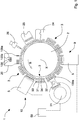
figure 1 is a plan schematic view from above of a capsule filling machine according to the invention; -
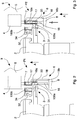
figures 2 to 5 are respective partial and enlarged sections of a movement device and of a weighing station of the filling machine offigure 1 , in subsequent stages of an operative sequence of a capsuleweighing; -
figure 6 is an enlarged and partial section of a gripping element offigure 2 associated to a body of a capsule; -
figure 7 is a perspective view of the gripping element offigure 6 ; -
figure 8 is a plan schematic view from above of a variant of the filling machine of the invention. - Referring to
figures 1 to 7 , itis schematically illustrated a filling machine1 according to the invention adapted to fillcapsules 100, casings or similar elements, for example hard gelatine capsules, with a liquid, powder, granule, time-release product, tablets etcetera, in particular a pharmaceutical product. Eachcapsule 100 is formed by abody 100a and acap 100b which can be temporarily uncoupled and separated to allow dosing the product in thebody 100a. - The
filling machine 1 comprises a plurality of operative stations 20-26 arranged tocarry out operations on thecapsules 100, amovement device 2 provided with a plurality ofsupports 3 withrespective seats capsules 100 in sequence through the operative stations 20-26, and at least oneweighing station 9 forweighing capsules 100 orbodies 100a of thecapsules 100. - The
movement device 2, of the known type, comprises a carousel or board, rotatable about a vertical rotation axis X and provided with a plurality ofsupports 3 arranged angularly spaced apart along the periphery or a circumferential rim of the aforesaid carousel. Eachsupport 3 is formed by a first supportingelement 31, having a plurality offirst seats 33 intended to house thebodies 100a of thecapsules 100, and a second supportingelement 32, having a plurality ofsecond seats 34 intended to housethecaps 100b of thecapsules 100. The supportingelements respective seats caps 100b applied to therespective bodies 100a) and a staggered position wherein thefirst seats 33 containing thebodies 100a are accessible for allowing the dosing of the product. - The
first seats 33 andsecond seats 34 of thesupports 3 comprise respectively pass-through cavities, i.e. open at opposite ends, and having convergent shape and/or properly shaped for receiving and holding by force or interference coupling thebodies 100a andcaps 100b of thecapsules 100. - In the illustrated embodiment, the
weighing station 9 is arranged to weighbodies 100a of thecapsules 100 and comprises aweighing unit 5 and transfer means 6 adapted to transfer thebodies 100a of thecapsules 100 from themovement device 2 to theweighing unit 5 and vice versa. - For this purpose the
filling machine 1 comprises among the plurality of operative stations 20-26 a supplying andopening station 20 of thecapsules 100 whereby the latter ones are introduced in thefilling machine 1, and thecaps 100b are extracted and separated from theirrespective bodies 10 as which can thus receive the product in asubsequent filling station 21. Thebodies 100a andcaps 100b are inserted and housed respectively into thefirst seats 33 and into thesecond seats 34 of thesupports 3 of themovement device 2. A capsule-closing station 24 is provided for coupling thecaps 100b with therespective bodies 100a and thus close thecapsules 100 after filling and weighing. - It is also provided,as better explained in the hereinafter description, that the
weighing station 9 is arranged for weighing all thecapsules 100. - The weighing
unit 5 of theweighing station 9 comprises at least one grippingelement 7 which is connected to a respective weighing cell orload cell 4 of theaforesaid weighing unit 5 and is provided with ahousing 17 suitable for receiving and holding by force or interference coupling abody 100a to be weighed. More precisely, theweighing unit 5 comprises a plurality ofgripping elements 7, in equal number as theseats support 3 of themovement device 2, and an equal number ofload cells 4. Thereby, allbodies 100a housed in thefirst seats 33 of a first supportingelement 31 of thesupport 3 can be weighed at the same time by the weighingunit 5. - The transfer means 6 are movable along a direction of extraction A, in particular almost vertical, and include at least a
first transfer element 16 arranged to remove onerespective body 100a from a respectivefirst seat 33 of asupport 3 of themovement device 2 and insert saidbody 100a, by forcing it, into thehousing 17 to allow theload cell 4 to measure its weight. - The transfer means 6 further comprise at least a
second transfer element 18 arranged for removing thebody 100a from thehousing 17 and inserting thebody 100a into the respectivefirst seat 33 of themovement device 2, after the weight of saidbody 100a is measured. - More precisely, the
first transfer element 16 and thesecond transfer element 18 are movable along the direction of extraction A between a first operative position P1, wherein theaforesaid transfer elements body 100a, housed in the respectivefirst seat 33 of asupport 3 of themovement device 2 such as not to interfere with the movement of the latter, a second operative position P2, wherein thefirst transfer element 16 has completely extracted thebody 100a from thefirst seat 33 and has inserted it inside thehousing 17 of thegripping element 7, a third operative position P3, wherein thetransfer elements body 100a housed and hold by force or interference in thehousing 17 such as to allow theload cell 4 to measure its weight, and a fourth operative position P4, wherein thesecond transfer element 18 has completely extracted thebody 100a from thehousing 17 and inserted it inside the respectivefirst seat 33. - In the illustrated embodiment, the transfer means 6 of the
weighing station 9 comprise a plurality offirst transfer elements 16 and a respective plurality ofsecond transfer elements 18, equal in number as theseats support 3 of themovement device 2, so as to transfer at the same time all thebodies 100a housed in thefirst seats 33 into thehousings 17 of thegripping elements 7 and vice versa. - The
weighing unit 5 with thegripping element 7 is arranged above themovement device 2 and thehousing 17 has alower opening 17a that enables the transfer means 6 to insert into, or remove from saidhousing 17 thebody 100a along the direction of extraction A. Thelower opening 17a of thehousing 17 has a blunted or rounded rim to ease the insertion of thebody 100a. - As illustrated in particular in
figures 6 and 7 , thehousing 17 extends longitudinally, in particular parallel to the direction of extraction A, and has such an extension that it contains thebody 100a orcapsule 100. Thehousing 17 is also convergent or tapered starting from thelower opening 17a towards theload cell 4, as its internal cross-section (almost orthogonal to a longitudinalaxis Y of thegripping element 7 which is parallel to the direction of extraction A) funnels gradually starting from thelower opening 17a to a smaller dimension of an external transverse dimension of thebody 100a, or of thecapsule 100. Thereby,once insertion is completed, thehousing 17 is able to hold thebody 100a by force or interference coupling. More precisely, thebody 100a can be inserted and gradually pushed into thehousing 17 wherein it stays reversibly fastened by virtue of the material elasticity (hard gelatine) it is made of and of its hollow shape. In the illustrated example, thecapsule 100, thebody 100a and thecap 100b have hollow cylindrical shape (thebody 100a and thecap 100b are also provided with respective sphere-shaped bottoms) and thehousing 17 has truncated-cone shape converging in the direction of theload cell 4, and circular inner transverse section. - The
gripping element 7 is removably connected to a stem orplate 41 of theload cell 4, extending vertically from the weighingunit 5 downwards. - The
first transfer element 16 has elongated shape and is arranged to be inserted, when moved along the direction of extraction A, inside a respectivefirst seat 33 of asupport 3 of themovement device 2 so as to abut onto the lower portion of thebody 100a and therefore push the latter outside thefirst seat 33 inside thehousing 17 along the direction of extraction A. More precisely, thefirst transfer element 16 is inserted into thefirst seat 33 through a lower opening of the latter so as to abut and push thebody 100a to exit from thefirst seat 33 through an opposite upper opening of the latter. - The
second transfer element 18 also has elongated shape and has at least oneterminal end 18a adapted to abut onto an upper portion of thebody 100a in order to push the latter outside thehousing 17 and inside thefirst seat 33. More in detail, thesecond transfer element 18 substantially has upside down "L" shape and comprises a firstelongated portion 18b, parallel to the direction of extraction A, and a second portion which is almost orthogonal to thefirst portion 18b and which forms theterminal end 18a. - The
first transfer element 16 and thesecond transfer element 18 are fixed to abase element 8 of the transfer means 6 which is moved by action means, of the known type and not illustrated in the figures, along the direction of extraction A, between the different operative positions P1, P2, P3, P4. - The
gripping element 7 also has one or morelateral opening 19, passing through and parallel to the direction of extraction A, which allow to insert and slide theterminal end 18a of thesecond transfer element 18 inside thehousing 17 and along the direction of extraction A. - Referring in particular to
figure 1 , the fillingmachine 1 of the invention comprises a fillingstation 21 arranged to dispense and dose a product in thebodies 100a of thecapsules 100; the weighingstation 9 is placed downstream of the fillingstation 21, referring to a movement direction B of thecapsules 100 in the fillingmachine 1, such as to measure the weight ofbodies 100a containing the product. - The filling
machine 1 also comprises astation of initial weighing 10 that is provided with a respective weighingunit 5 and with respective transfer means 6 and is placed upstream of the fillingmachine 21, with reference to the movement direction B, in such a way as to measure the weight of theempty bodies 100a. In such an embodiment of the fillingmachine 1 of the invention, the supplying andopening station 20, wherein thecaps 100b were extracted and separated from therespective bodies 100a, is placed upstream of the station of initial weighing 10, while thecapsule closing station 24, wherein thecaps 100b are reapplied to therespective bodies 100a so as to reclose thecapsules 100, is placed downstream of the weighingstation 9. - The filling
machine 1 of the invention further comprises aprocessing unit 50 connected to the weighingstation 9 and to the station of initial weighing 10 and arranged to receive data about the measured weights and calculate aneffective weight of the product dosed in eachcapsule 100 orrespective body 100a and generate a warning signal in case of a non-compliant capsule or respective non-compliant body - as containing an amount of product having a weight outside the admitted tolerance field. - The plurality of operative stations 20-26 of the filling machine includes, furthermore, an
exit station 25 wherein thecapsules 100 filled with the product and compliant are extracted from themovement device 2 and conveyed outside the fillingmachine 1. Theexit station 25 is connected to theprocessing unit 50 for receiving from the latter the warning signal and leave non-compliant capsules on themovement device 2. A discardstation 26 is provided downstream of theexit station 25 to remove from themovement device 2 non-compliant capsules. - The filling
station 21 is also connected to theprocessing unit 50 to receive therefrom the warning signal and stop such as to interrupt the filling offurther capsules 100 which would result to be non-compliant. - The functioning of the filling
machine 1 of the invention provides thatclosed capsules 100, i.e. havingcaps 100b coupled withrespective bodies 100a, are introduced in the fillingmachine 1 in the supplying andopening station 20. In such a station, thebodies 100a and thecaps 100b are separated and inserted respectively in thefirst seats 33 and in thesecond seats 34 of thesupports 3 of themovement device 2. - The latter comprises a rotatable carousel rotating with intermittent motion about the rotation axis X such as to transfer the
open capsules 100, i.e. havingbodies 100a and caps 100b separated, through the subsequent operative stations 20-26 and weighingstations - In particular, in the station of initial weighing 10 the relative transfer means 6, in one of the stop stages of the intermittent motion, transfer the
empty bodies 100a, contained in the first supportingelement 31 of asupport 3, in the respectivegripping elements 7 of the weighingunit 5. More precisely, thefirst transfer elements 16 of the transfer means 6 are moved, together with thesecond transfer elements 18, from the first operative position P1 (figure 2 ) to the second operative position P2 (figure 3 ) such as to remove thebodies 100a from the respectivefirst seats 33 and insert them, pushing them, into therespective housings 17 of thegripping elements 7. Thetransfer elements figure 4 ) wherein they are disengaged and spaced from thebody 100a housed and hold by force or interference in thehousing 17 to allow the weighingcell 4 to measure the weight of thebody 100a. - Once detection of the
empty bodies 100a weight is over, thetransfer elements second transfer elements 18 can remove thebodies 100a from thehousings 17 of thegripping elements 7 and insert them completely into their respectivefirst seats 33 of thesupport 3. - Similarly to the weighing
station 9 placed downstream of the fillingstation 21,the relative transfer means 6, in one of the stop stages of the intermittent motion, thetransfer bodies 100a, filled with the product, from thefirst seats 33 of thesupport 3 into thehousings 17 of thegripping elements 7 of the weighingunit 5. - The sequence of movements of the
first transfer elements 16 andsecond transfer elements 18 of the transfer means 6 between the different and subsequent operativepositions P1-P4 is the same as the previously described one for the station of initial weighing 10, in thiscase weighing cells 4 of the weighingunits 5 of the weighingstations 9 measuring a weight of thebodies 100a containing the product. - It is worth noting that thanks to transfer means 6 and
gripping elements 7 receiving and holding byforce bodies 100a of thecapsules 100 it is possible to transfer very rapidly, easily and efficiently theaforesaid bodies 100a from/to themovement device 2 and allow to weigh precisely and accurately by means ofload cells 4, connected directly to the aforesaidgripping elements 7, thebodies 100a, both empty and containing the product. Thefirst transfer elements 16 andsecond transfer elements 18 are in fact moved linearly along the direction of extraction A with short run, which can thus be carried out in short times, between the various operative positions P1-P4. Therefore, the time necessary to carry out the whole weighing operation - which comprises the transfer of thebody 100a from themovement device 2 to thegripping element 7 of theload cell 4, the weighing thereof on the latter and transfer thereof from thegripping element 7 to the movement device 2- is very short and can be equal to the duration of the stop intervals of an intermittent motion of the fillingmachine 1 also having high rate or speed or productivity. In other words, thanks to the fillingmachine 1 of the invention it is possible to carry out a total weight control of thecapsules 100 without reducing the functioning speed of the latter, which can thus be very high and the same as that of known filling machines which carry out a partial control of statistical type of capsules or a control of the total type but with limited precisionand accuracy. - The
processing unit 50 connected to the weighingstation 9 and to the station of initial weighing 10 receives data relative to measured weights such as to calculate the effective weight of the product dosed in eachbody 100a and generate a warning signal in case of anon-compliant body 100a, as containing a quantity of product with a weight outside the admitted tolerance range. Such a warning signal is sent to theexit station 25, which keeps on themovement device 2 the non-compliant capsules intended to be removed from the latter in the following discardstation 26. - As the weighing
station 9 is placed immediately downstream of the fillingstation 21, in case an anomaly is detected in the filling i.e. a malfunction of the filling station 21 (highlighted by the measurement of a weight of the dosed product outside the admitted tolerance range), it is possible to interrupt immediately the filling of thebodies 100a, i.e. the functioning of the fillingstation 21 in order to reduce the number of non-compliant capsules to discard. In particular, the capsules to be discarded are only those contained in thesupports 3 comprised between the fillingstation 21 and the weighingstation 9, therefore a reduced number. - In one variant of the filling
machine 1 of the invention non shown in the figures, it is provided that the weighingstation 9 is placed downstream of thecapsule closing station 24 and that the station of initial weighing 10 is placed upstream of acapsule opening station 100, i.e. interposed between the latter and the supplying station wherein the capsules are introduced into the fillingmachine 1. In this variant of the fillingmachine 1 of the invention, the transfer means 6 of the weighingstations capsules 100 respectively empty and filled with the product, from themovement device 2 to thegripping element 7 and vice versa, i.e. the weight of all thecapsules 100 is weighed. -
Figure 8 illustrates another variant of the fillingmachine 1 of the invention which differs from the previously described embodiment in that it comprises a plurality of fillingstations bodies 100a of thecapsules 100. The fillingmachine 1 further includes a plurality of weighingstations respective filling stations bodies 100a filled with different products. The number of weighingstations stations - The filling
machine 1 also includes the station of initial weighing 10 which measures the weight of theempty bodies 100a and it is thus placed upstream of the fillingstations opening station 20 of thecapsules 100. Aprocessing unit 50 is connected to the weighingstations bodies 100a in the fillingstations processing unit 50 is also able to generate a warning signal in case thebody 100a is non-compliant i.e. it contains an amount of product having a weight outside the admitted tolerance field. - The
exit station 25 is connected to theoperative unit 50 for receiving from the latter the warning signal and leave the non-compliant capsules on themovement device 2. The discardstation 26, provided downstream of theexit station 25, removesthe non-compliant capsulesfrom themovement device 2. - The filling
stations processing unit 50 to receive therefrom the warning signal and stop such as to interrupt the filling offurther capsules 100 which would result to be non-compliant. - In the filling
machine 1 of the invention, thanks to the weighingstations stations capsules 100, i.e. possible malfunction of fillingstations - In this version also of the filling
machine 1, thanks to the transfer means 6 and thegripping elements 7 included in each of the weighingstations bodies 100a from/to themovement device 2 and weigh precisely and accurately throughload cells 4, directly connected to thegripping elements 7, thebodies 100a, empty and containing the different products. - The
first transfer elements 16 andsecond transfer elements 18 of the transfer means 6 are in fact moved along the direction of extraction A with short-length stroke between the various operative positions P1-P4, which can be carried out very quickly. Therefore, the time required to carry out the whole weighing operation in the different weighingstations machine 1 having high rate or speed or productivity. Therefore the fillingmachine 1 of the invention carries out a total weight control ofcapsules 100 even at high operative speeds.
Claims (12)
- Filling machine (1) for filling capsules (100) or similar elements with at least one product, each capsule (100) having a body (100a) and a cap (100b), comprising:- a plurality of operative stations (20-26) for carrying out operations on said capsules (100);- a movement device (2) provided with a plurality of supports (3) with respective seats (33, 34) for housing and moving said capsules (100) in sequence through said operative stations (20-26); and- at least one weighing station (9, 10, 11, 12) to weigh at least bodies (100a) of said capsules (100), comprising a weighing unit (5) and transfer means (6) to transfer at least said bodies (100a) from said movement device (2) to said weighing unit (5) and vice versa;characterized in that said weighing unit (5) comprises at least one gripping element (7) connected to a respective weighing cell (4) of said weighing unit (5) and provided with a housing (17) suitable for receiving and holding by force coupling at least one body (100a) to be weighed, said transfer means (6) being moveable along a direction of extraction (A) and including a first transfer element (16) arranged to remove said at least one body (100a) from a respective first seat (33) of said movement device (2) and insert the body (100a) into said housing (17) to allow said weighing cell (4) to measure the weight of said body (100a), and a second transfer element (18) to remove said at least one body (100a) from said housing (17) and insert said at least one body (100a) into the respective first seat (33) of said movement device (2), after the weight of said body (100a) is measured.
- Filling machine (1) according to claim 1, wherein said first transfer element (16) and said second transfer element (18) are moveable along said direction of extraction (A), in particular substantially vertical, between a first operative position (P1), wherein said transfer elements (16, 18) are disengaged and spaced apart from said at least one body (100a), which is housed in the respective first seat (33) of said movement device (2) such as not to interfere with the movement of the latter, a second operative position (P2), wherein said first transfer element (16) has completely extracted said at least one body (100a) from said first seat (33) and has inserted said at least one body (100a) inside said housing (17) of the gripping element (7), a third operative position (P3), wherein said transfer elements (16, 18) are disengaged and spaced apart from said at least one body (100a) housed and holdby force or interference in said housing (17) so that said weighing cell (4) can measure the weight thereof, and a fourth operative position (P4), wherein said second transfer element (18) has completely extracted said at least one body (100a) from said housing (17) and has inserted said at least one body (100a) inside the respective first seat (33) of said movement device (2).
- Filling machine (1) according to claim 1 or 2, wherein said weighing unit (5) with said at least one gripping element (7) is arranged above said movement device (2), said housing (17) having a lower opening (17a) that enables said transfer means (6) to insert in, or extract from, said housing (17) said at least one body (100a) along said direction of extraction (A).
- Filling machine (1) according to any preceding claim, wherein said first transfer element (16) has an elongated shape and is arranged to be inserted, when moved along said direction of extraction (A), inside a respective first seat (33) of said movement device (2) to abut onto a lower portion of at least one body (100a) and push the latter outside said first seat (33) and inside said housing (17).
- Filling machine (1) according to any preceding claim, wherein said second transfer element (18) has an elongated shape and has at least one terminal end (18a) adapted to abut onto an upper portion of said at least one body (100a) in order to push the latter outside said housing (17) and inside said first seat (33).
- Filling machine (1) according to claim 5, wherein said gripping element (7) has at least one lateral opening (19), in particular parallel to said direction of extraction (A), for inserting and sliding said terminal end (18a) of said second transfer element (18) inside said housing (17) and along said direction of extraction (A).
- Filling machine (1) according to any preceding claim, wherein said housing (17) extends longitudinally, in particular parallel to said direction of extraction (A), and is convergent starting from a lower opening (17a) arranged for the insertion and extraction of said at least one body (100a), and towards said weighing cell (4), an internal cross-section of said housing (17) progressively funneling from said lower opening (17a) to a smaller dimension of an external transverse dimension of said at least one body (100a) so as to receive and hold the latterby force or interferencecoupling.
- Filling machine (1) according to any preceding claim, wherein said plurality of operative stations (20-26) comprises at least one filling station (21) arranged to dispense a product into the bodies (100a) of said capsules (100), said weighing station (9) being placed downstream of said filling station (21), with reference to a movement direction (B) of said capsules (100) in said filling machine (1), to measure the weightof said bodies (100a) containing said product.
- Filling machine (1) according to claim 8, comprising a station of initial weighing (10) provided with a respective weighing unit (5) and with respective transfer means (6) and placed upstream of said filling station (21), with reference to said movement direction (B), to measure the weight of said empty bodies (100a).
- Filling machine (1) according to claim 9, comprising a processing unit (50) connected to said weighing station (9) and to said station of initial weighing (10) and configured to receive data about the measured weights, calculate an effective weight of the product dosed in each capsule (100) and generate a warning signal in case of a non-compliant capsule.
- Filling machine (1) according to any preceding claim, wherein said plurality of operative stations (20-26) comprises a plurality of filling stations (21, 22, 23) arranged to supply respective products in the bodies (100a) of said capsules (100), a plurality of weighing stations (9, 11, 12) placed downstream of the respective filling stations (21, 22, 23), with reference to said movement direction (B), and configured to measure the weight of said bodies (100a) filled with said products, and a station of initial weighing (10) placed upstream of said filling stations (21, 22, 23) to measure the weight of said empty bodies (100a).
- Filling machine (1) according to any preceding claim, wherein said movement device (2) comprises a carousel rotating about a vertical rotation axis (X) and provided with said plurality of supports (3), placed angularly spaced apart along a circumferential rim of said carousel.
Applications Claiming Priority (2)
| Application Number | Priority Date | Filing Date | Title |
|---|---|---|---|
| IT102017000123930A IT201700123930A1 (en) | 2017-10-31 | 2017-10-31 | Filling machine. |
| PCT/IB2018/058494 WO2019087066A1 (en) | 2017-10-31 | 2018-10-30 | Filling machine |
Publications (2)
| Publication Number | Publication Date |
|---|---|
| EP3703644A1 EP3703644A1 (en) | 2020-09-09 |
| EP3703644B1 true EP3703644B1 (en) | 2021-07-14 |
Family
ID=61527006
Family Applications (1)
| Application Number | Title | Priority Date | Filing Date |
|---|---|---|---|
| EP18812253.5A Active EP3703644B1 (en) | 2017-10-31 | 2018-10-30 | Filling machine |
Country Status (7)
| Country | Link |
|---|---|
| US (1) | US11376196B2 (en) |
| EP (1) | EP3703644B1 (en) |
| KR (1) | KR102450818B1 (en) |
| CN (1) | CN111315340B (en) |
| ES (1) | ES2886250T3 (en) |
| IT (1) | IT201700123930A1 (en) |
| WO (1) | WO2019087066A1 (en) |
Families Citing this family (11)
| Publication number | Priority date | Publication date | Assignee | Title |
|---|---|---|---|---|
| IT201700018745A1 (en) * | 2017-02-20 | 2018-08-20 | Gd Spa | Method and device for controlling the amount of liquid contained in a cartridge for an aerosol generating device |
| KR102759059B1 (en) | 2019-05-13 | 2025-01-24 | 아이.엠.에이. 인듀스트리아 마친 오토메티크 에스.피.에이. | Mass measuring device and mass measuring method for automatic processing machines |
| IT201900006838A1 (en) * | 2019-05-15 | 2020-11-15 | Ima Spa | Weighing system for a capsule filling machine. |
| IT202000010855A1 (en) * | 2020-05-13 | 2021-11-13 | Ima Spa | MACHINE TO FILL CAPSULES. |
| IT202000011485A1 (en) | 2020-05-19 | 2021-11-19 | Ima Spa | METHOD OF HANDLING CONTAINERS IN A PROCESSING LINE OF SUCH CONTAINERS, AND RELATIVE PROCESSING LINE. |
| CN112874900A (en) * | 2021-01-28 | 2021-06-01 | 谈文娟 | Preparation method of probiotic health-care capsule |
| JP2023004471A (en) * | 2021-06-25 | 2023-01-17 | 澁谷工業株式会社 | Filling device |
| IT202100019868A1 (en) | 2021-07-26 | 2023-01-26 | Ima Spa | Tablet dispenser. |
| EP4282395B1 (en) * | 2022-05-23 | 2024-09-25 | Harro Höfliger Verpackungsmaschinen GmbH | Capsule filling machine |
| DE102022130430B4 (en) * | 2022-11-17 | 2025-04-10 | Syntegon Technology Gmbh | Capsule filling machine for filling a capsule and method for operating a capsule filling machine |
| CN116968959B (en) * | 2023-08-16 | 2025-07-11 | 安徽省力捷机器人技术应用有限公司 | Automatic powder quantitative servo weighing packaging machine and feeding weighing control method |
Family Cites Families (21)
| Publication number | Priority date | Publication date | Assignee | Title |
|---|---|---|---|---|
| FR2720824B1 (en) * | 1994-06-02 | 1997-01-24 | Macofar Spa | Method for online control of the weight of capsules and relative apparatus. |
| JP3343480B2 (en) * | 1996-08-05 | 2002-11-11 | アンリツ株式会社 | Capsule weight measuring device |
| IT1304779B1 (en) * | 1998-12-03 | 2001-03-29 | Ima Spa | DISC AND PESTEL DISPENSER, INTERMITTENTLY OPERATING, SINGLE-SIDED, PARTICULARLY SUITABLE FOR PACKAGING DOSES |
| ITBO20020282A1 (en) | 2002-05-13 | 2003-11-13 | Bl Macchine Automatiche | WRAPPING MACHINE FOR THE PACKAGING OF INCONERENT PRODUCTS IN HARD JELLY CAPSULES |
| ITBO20020431A1 (en) * | 2002-07-03 | 2004-01-05 | Ima Spa | UNIT FOR THE CONTROL OF THE DOSAGE OF PHARMACEUTICAL MATERIAL IN AN OPERATING MACHINE |
| GB0414813D0 (en) * | 2004-07-01 | 2004-08-04 | Meridica Ltd | Dispensing small quantities of powder |
| EP1762512B1 (en) * | 2005-09-09 | 2008-07-30 | MG2 S.r.l. | Device for conveying capsules containing at least one pharmaceutical product |
| DE102005057393A1 (en) * | 2005-11-30 | 2007-05-31 | Robert Bosch Gmbh | Weighing device e.g. intermittent capsule filling machine for filling a product to be dosed into capsule, has first and second weighing device whereby second weighing device which detects net weight of capsule |
| DE602007007054D1 (en) * | 2007-04-19 | 2010-07-22 | Mg2 Srl | Apparatus and method for filling capsules |
| WO2010003280A1 (en) * | 2008-07-09 | 2010-01-14 | 上海恒谊制药设备有限公司 | Apparatus for quickly detecting weight of capsules |
| IT1392005B1 (en) | 2008-11-28 | 2012-02-09 | Ima Spa | MACHINE AND METHOD FOR FILLING AND WEIGHING CAPSULES |
| IT1392277B1 (en) * | 2008-12-18 | 2012-02-24 | Ima Spa | MACHINE AND METHOD TO FILL AND CHECK CAPSULES |
| DE102010038544A1 (en) * | 2009-10-19 | 2011-04-21 | Robert Bosch Gmbh | Sensor device for a packaging machine |
| IT1401415B1 (en) * | 2010-08-20 | 2013-07-26 | Ima Spa | SYSTEM AND METHOD FOR WEIGHING ITEMS |
| DE102011085283B4 (en) * | 2011-02-21 | 2025-03-27 | Syntegon Technology Gmbh | Device for dosing powdered filling material |
| DE102012212033A1 (en) * | 2012-07-10 | 2014-01-16 | Robert Bosch Gmbh | Capsule weighing apparatus, capsule filling machine and method for weighing a capsule |
| ITBO20130178A1 (en) * | 2013-04-19 | 2014-10-20 | Mg 2 Srl | CONTINUOUS ROTARY MACHINE FOR FILLING CAPSULES WITH PHARMACEUTICALS |
| ITBO20130440A1 (en) | 2013-08-05 | 2015-02-06 | I M A Ind Macchine Automatic He S P A | FILLING MACHINE AND METHOD FOR WEIGHING ITEMS |
| ITBO20130488A1 (en) | 2013-09-12 | 2015-03-13 | I M A Ind Macchine Automatic He S P A | METHOD FOR WEIGHING CONTAINERS IN A FILLING AND RELATED MACHINE MACHINE |
| PL3307637T3 (en) * | 2015-06-09 | 2020-11-16 | Sluis Cigar Machinery B.V. | Filling station and method for filling cartridges of electronic cigarettes |
| DE102018200068A1 (en) * | 2018-01-04 | 2019-07-04 | Robert Bosch Gmbh | Device for determining the weight of a capsule arranged in a capsule holder of a stepwise rotated delivery wheel |
-
2017
- 2017-10-31 IT IT102017000123930A patent/IT201700123930A1/en unknown
-
2018
- 2018-10-30 KR KR1020207015443A patent/KR102450818B1/en active Active
- 2018-10-30 CN CN201880070881.0A patent/CN111315340B/en active Active
- 2018-10-30 US US16/760,614 patent/US11376196B2/en active Active
- 2018-10-30 ES ES18812253T patent/ES2886250T3/en active Active
- 2018-10-30 WO PCT/IB2018/058494 patent/WO2019087066A1/en not_active Ceased
- 2018-10-30 EP EP18812253.5A patent/EP3703644B1/en active Active
Also Published As
| Publication number | Publication date |
|---|---|
| US20210177700A1 (en) | 2021-06-17 |
| WO2019087066A1 (en) | 2019-05-09 |
| CN111315340A (en) | 2020-06-19 |
| US11376196B2 (en) | 2022-07-05 |
| IT201700123930A1 (en) | 2019-05-01 |
| CN111315340B (en) | 2022-03-22 |
| EP3703644A1 (en) | 2020-09-09 |
| ES2886250T3 (en) | 2021-12-16 |
| KR20200074994A (en) | 2020-06-25 |
| KR102450818B1 (en) | 2022-10-06 |
Similar Documents
| Publication | Publication Date | Title |
|---|---|---|
| US11376196B2 (en) | Filling machine | |
| US9021772B2 (en) | Machine and method for filling and weighing capsules | |
| US9157784B2 (en) | Machine and method for filling and checking capsules | |
| EP2205489B1 (en) | Apparatus and method for weighing containers | |
| KR102759060B1 (en) | Metering system for capsule filling machine | |
| US20130206484A1 (en) | System and method for weighing articles | |
| EP2851060A2 (en) | Filling machine and method for weighing articles | |
| EP2851303B1 (en) | Method for weighing containers in a filling machine and related machine | |
| EP1941249B1 (en) | Apparatus and corresponding method for weighing containers | |
| US11987414B2 (en) | Capsule filling machine for filling two-piece capsules, and method for filling two-piece capsules | |
| EP4734907A1 (en) | Apparatus and method for weighing and feeding capsules |
Legal Events
| Date | Code | Title | Description |
|---|---|---|---|
| STAA | Information on the status of an ep patent application or granted ep patent |
Free format text: STATUS: UNKNOWN |
|
| STAA | Information on the status of an ep patent application or granted ep patent |
Free format text: STATUS: THE INTERNATIONAL PUBLICATION HAS BEEN MADE |
|
| PUAI | Public reference made under article 153(3) epc to a published international application that has entered the european phase |
Free format text: ORIGINAL CODE: 0009012 |
|
| STAA | Information on the status of an ep patent application or granted ep patent |
Free format text: STATUS: REQUEST FOR EXAMINATION WAS MADE |
|
| 17P | Request for examination filed |
Effective date: 20200528 |
|
| AK | Designated contracting states |
Kind code of ref document: A1 Designated state(s): AL AT BE BG CH CY CZ DE DK EE ES FI FR GB GR HR HU IE IS IT LI LT LU LV MC MK MT NL NO PL PT RO RS SE SI SK SM TR |
|
| AX | Request for extension of the european patent |
Extension state: BA ME |
|
| DAV | Request for validation of the european patent (deleted) | ||
| DAX | Request for extension of the european patent (deleted) | ||
| GRAP | Despatch of communication of intention to grant a patent |
Free format text: ORIGINAL CODE: EPIDOSNIGR1 |
|
| STAA | Information on the status of an ep patent application or granted ep patent |
Free format text: STATUS: GRANT OF PATENT IS INTENDED |
|
| INTG | Intention to grant announced |
Effective date: 20210322 |
|
| GRAS | Grant fee paid |
Free format text: ORIGINAL CODE: EPIDOSNIGR3 |
|
| GRAA | (expected) grant |
Free format text: ORIGINAL CODE: 0009210 |
|
| STAA | Information on the status of an ep patent application or granted ep patent |
Free format text: STATUS: THE PATENT HAS BEEN GRANTED |
|
| AK | Designated contracting states |
Kind code of ref document: B1 Designated state(s): AL AT BE BG CH CY CZ DE DK EE ES FI FR GB GR HR HU IE IS IT LI LT LU LV MC MK MT NL NO PL PT RO RS SE SI SK SM TR |
|
| REG | Reference to a national code |
Ref country code: GB Ref legal event code: FG4D |
|
| REG | Reference to a national code |
Ref country code: DE Ref legal event code: R096 Ref document number: 602018020216 Country of ref document: DE |
|
| REG | Reference to a national code |
Ref country code: IE Ref legal event code: FG4D |
|
| REG | Reference to a national code |
Ref country code: AT Ref legal event code: REF Ref document number: 1410091 Country of ref document: AT Kind code of ref document: T Effective date: 20210815 |
|
| REG | Reference to a national code |
Ref country code: LT Ref legal event code: MG9D |
|
| REG | Reference to a national code |
Ref country code: NL Ref legal event code: MP Effective date: 20210714 |
|
| REG | Reference to a national code |
Ref country code: AT Ref legal event code: MK05 Ref document number: 1410091 Country of ref document: AT Kind code of ref document: T Effective date: 20210714 |
|
| REG | Reference to a national code |
Ref country code: ES Ref legal event code: FG2A Ref document number: 2886250 Country of ref document: ES Kind code of ref document: T3 Effective date: 20211216 |
|
| PG25 | Lapsed in a contracting state [announced via postgrant information from national office to epo] |
Ref country code: RS Free format text: LAPSE BECAUSE OF FAILURE TO SUBMIT A TRANSLATION OF THE DESCRIPTION OR TO PAY THE FEE WITHIN THE PRESCRIBED TIME-LIMIT Effective date: 20210714 Ref country code: SE Free format text: LAPSE BECAUSE OF FAILURE TO SUBMIT A TRANSLATION OF THE DESCRIPTION OR TO PAY THE FEE WITHIN THE PRESCRIBED TIME-LIMIT Effective date: 20210714 Ref country code: FI Free format text: LAPSE BECAUSE OF FAILURE TO SUBMIT A TRANSLATION OF THE DESCRIPTION OR TO PAY THE FEE WITHIN THE PRESCRIBED TIME-LIMIT Effective date: 20210714 Ref country code: PT Free format text: LAPSE BECAUSE OF FAILURE TO SUBMIT A TRANSLATION OF THE DESCRIPTION OR TO PAY THE FEE WITHIN THE PRESCRIBED TIME-LIMIT Effective date: 20211115 Ref country code: NL Free format text: LAPSE BECAUSE OF FAILURE TO SUBMIT A TRANSLATION OF THE DESCRIPTION OR TO PAY THE FEE WITHIN THE PRESCRIBED TIME-LIMIT Effective date: 20210714 Ref country code: NO Free format text: LAPSE BECAUSE OF FAILURE TO SUBMIT A TRANSLATION OF THE DESCRIPTION OR TO PAY THE FEE WITHIN THE PRESCRIBED TIME-LIMIT Effective date: 20211014 Ref country code: HR Free format text: LAPSE BECAUSE OF FAILURE TO SUBMIT A TRANSLATION OF THE DESCRIPTION OR TO PAY THE FEE WITHIN THE PRESCRIBED TIME-LIMIT Effective date: 20210714 Ref country code: AT Free format text: LAPSE BECAUSE OF FAILURE TO SUBMIT A TRANSLATION OF THE DESCRIPTION OR TO PAY THE FEE WITHIN THE PRESCRIBED TIME-LIMIT Effective date: 20210714 Ref country code: BG Free format text: LAPSE BECAUSE OF FAILURE TO SUBMIT A TRANSLATION OF THE DESCRIPTION OR TO PAY THE FEE WITHIN THE PRESCRIBED TIME-LIMIT Effective date: 20211014 Ref country code: LT Free format text: LAPSE BECAUSE OF FAILURE TO SUBMIT A TRANSLATION OF THE DESCRIPTION OR TO PAY THE FEE WITHIN THE PRESCRIBED TIME-LIMIT Effective date: 20210714 |
|
| PG25 | Lapsed in a contracting state [announced via postgrant information from national office to epo] |
Ref country code: PL Free format text: LAPSE BECAUSE OF FAILURE TO SUBMIT A TRANSLATION OF THE DESCRIPTION OR TO PAY THE FEE WITHIN THE PRESCRIBED TIME-LIMIT Effective date: 20210714 Ref country code: LV Free format text: LAPSE BECAUSE OF FAILURE TO SUBMIT A TRANSLATION OF THE DESCRIPTION OR TO PAY THE FEE WITHIN THE PRESCRIBED TIME-LIMIT Effective date: 20210714 Ref country code: GR Free format text: LAPSE BECAUSE OF FAILURE TO SUBMIT A TRANSLATION OF THE DESCRIPTION OR TO PAY THE FEE WITHIN THE PRESCRIBED TIME-LIMIT Effective date: 20211015 |
|
| REG | Reference to a national code |
Ref country code: DE Ref legal event code: R097 Ref document number: 602018020216 Country of ref document: DE |
|
| PG25 | Lapsed in a contracting state [announced via postgrant information from national office to epo] |
Ref country code: DK Free format text: LAPSE BECAUSE OF FAILURE TO SUBMIT A TRANSLATION OF THE DESCRIPTION OR TO PAY THE FEE WITHIN THE PRESCRIBED TIME-LIMIT Effective date: 20210714 |
|
| PLBE | No opposition filed within time limit |
Free format text: ORIGINAL CODE: 0009261 |
|
| STAA | Information on the status of an ep patent application or granted ep patent |
Free format text: STATUS: NO OPPOSITION FILED WITHIN TIME LIMIT |
|
| PG25 | Lapsed in a contracting state [announced via postgrant information from national office to epo] |
Ref country code: SM Free format text: LAPSE BECAUSE OF FAILURE TO SUBMIT A TRANSLATION OF THE DESCRIPTION OR TO PAY THE FEE WITHIN THE PRESCRIBED TIME-LIMIT Effective date: 20210714 Ref country code: SK Free format text: LAPSE BECAUSE OF FAILURE TO SUBMIT A TRANSLATION OF THE DESCRIPTION OR TO PAY THE FEE WITHIN THE PRESCRIBED TIME-LIMIT Effective date: 20210714 Ref country code: RO Free format text: LAPSE BECAUSE OF FAILURE TO SUBMIT A TRANSLATION OF THE DESCRIPTION OR TO PAY THE FEE WITHIN THE PRESCRIBED TIME-LIMIT Effective date: 20210714 Ref country code: EE Free format text: LAPSE BECAUSE OF FAILURE TO SUBMIT A TRANSLATION OF THE DESCRIPTION OR TO PAY THE FEE WITHIN THE PRESCRIBED TIME-LIMIT Effective date: 20210714 Ref country code: CZ Free format text: LAPSE BECAUSE OF FAILURE TO SUBMIT A TRANSLATION OF THE DESCRIPTION OR TO PAY THE FEE WITHIN THE PRESCRIBED TIME-LIMIT Effective date: 20210714 Ref country code: AL Free format text: LAPSE BECAUSE OF FAILURE TO SUBMIT A TRANSLATION OF THE DESCRIPTION OR TO PAY THE FEE WITHIN THE PRESCRIBED TIME-LIMIT Effective date: 20210714 |
|
| REG | Reference to a national code |
Ref country code: CH Ref legal event code: PL |
|
| 26N | No opposition filed |
Effective date: 20220419 |
|
| REG | Reference to a national code |
Ref country code: BE Ref legal event code: MM Effective date: 20211031 |
|
| PG25 | Lapsed in a contracting state [announced via postgrant information from national office to epo] |
Ref country code: MC Free format text: LAPSE BECAUSE OF FAILURE TO SUBMIT A TRANSLATION OF THE DESCRIPTION OR TO PAY THE FEE WITHIN THE PRESCRIBED TIME-LIMIT Effective date: 20210714 |
|
| PG25 | Lapsed in a contracting state [announced via postgrant information from national office to epo] |
Ref country code: LU Free format text: LAPSE BECAUSE OF NON-PAYMENT OF DUE FEES Effective date: 20211030 Ref country code: BE Free format text: LAPSE BECAUSE OF NON-PAYMENT OF DUE FEES Effective date: 20211031 |
|
| PG25 | Lapsed in a contracting state [announced via postgrant information from national office to epo] |
Ref country code: LI Free format text: LAPSE BECAUSE OF NON-PAYMENT OF DUE FEES Effective date: 20211031 Ref country code: CH Free format text: LAPSE BECAUSE OF NON-PAYMENT OF DUE FEES Effective date: 20211031 |
|
| PG25 | Lapsed in a contracting state [announced via postgrant information from national office to epo] |
Ref country code: IE Free format text: LAPSE BECAUSE OF NON-PAYMENT OF DUE FEES Effective date: 20211030 |
|
| P01 | Opt-out of the competence of the unified patent court (upc) registered |
Effective date: 20230509 |
|
| PG25 | Lapsed in a contracting state [announced via postgrant information from national office to epo] |
Ref country code: CY Free format text: LAPSE BECAUSE OF FAILURE TO SUBMIT A TRANSLATION OF THE DESCRIPTION OR TO PAY THE FEE WITHIN THE PRESCRIBED TIME-LIMIT Effective date: 20210714 |
|
| PG25 | Lapsed in a contracting state [announced via postgrant information from national office to epo] |
Ref country code: HU Free format text: LAPSE BECAUSE OF FAILURE TO SUBMIT A TRANSLATION OF THE DESCRIPTION OR TO PAY THE FEE WITHIN THE PRESCRIBED TIME-LIMIT; INVALID AB INITIO Effective date: 20181030 |
|
| PG25 | Lapsed in a contracting state [announced via postgrant information from national office to epo] |
Ref country code: MK Free format text: LAPSE BECAUSE OF FAILURE TO SUBMIT A TRANSLATION OF THE DESCRIPTION OR TO PAY THE FEE WITHIN THE PRESCRIBED TIME-LIMIT Effective date: 20210714 |
|
| PG25 | Lapsed in a contracting state [announced via postgrant information from national office to epo] |
Ref country code: MT Free format text: LAPSE BECAUSE OF FAILURE TO SUBMIT A TRANSLATION OF THE DESCRIPTION OR TO PAY THE FEE WITHIN THE PRESCRIBED TIME-LIMIT Effective date: 20210714 |
|
| PGFP | Annual fee paid to national office [announced via postgrant information from national office to epo] |
Ref country code: IT Payment date: 20250923 Year of fee payment: 8 |
|
| PGFP | Annual fee paid to national office [announced via postgrant information from national office to epo] |
Ref country code: GB Payment date: 20250923 Year of fee payment: 8 |
|
| PGFP | Annual fee paid to national office [announced via postgrant information from national office to epo] |
Ref country code: FR Payment date: 20250925 Year of fee payment: 8 |
|
| PG25 | Lapsed in a contracting state [announced via postgrant information from national office to epo] |
Ref country code: TR Free format text: LAPSE BECAUSE OF FAILURE TO SUBMIT A TRANSLATION OF THE DESCRIPTION OR TO PAY THE FEE WITHIN THE PRESCRIBED TIME-LIMIT Effective date: 20210714 |
|
| PGFP | Annual fee paid to national office [announced via postgrant information from national office to epo] |
Ref country code: DE Payment date: 20250923 Year of fee payment: 8 |
|
| PGFP | Annual fee paid to national office [announced via postgrant information from national office to epo] |
Ref country code: ES Payment date: 20251103 Year of fee payment: 8 |