EP3703478A1 - Fan cover - Google Patents
Fan cover Download PDFInfo
- Publication number
- EP3703478A1 EP3703478A1 EP20159324.1A EP20159324A EP3703478A1 EP 3703478 A1 EP3703478 A1 EP 3703478A1 EP 20159324 A EP20159324 A EP 20159324A EP 3703478 A1 EP3703478 A1 EP 3703478A1
- Authority
- EP
- European Patent Office
- Prior art keywords
- fan
- fan cover
- spiral
- frame
- cover
- Prior art date
- Legal status (The legal status is an assumption and is not a legal conclusion. Google has not performed a legal analysis and makes no representation as to the accuracy of the status listed.)
- Withdrawn
Links
- 239000004033 plastic Substances 0.000 claims description 8
- 238000010276 construction Methods 0.000 claims description 6
- 239000000463 material Substances 0.000 claims description 6
- 238000001816 cooling Methods 0.000 description 13
- 238000000034 method Methods 0.000 description 5
- 229910000831 Steel Inorganic materials 0.000 description 4
- 229910052782 aluminium Inorganic materials 0.000 description 4
- XAGFODPZIPBFFR-UHFFFAOYSA-N aluminium Chemical compound [Al] XAGFODPZIPBFFR-UHFFFAOYSA-N 0.000 description 4
- 229910001220 stainless steel Inorganic materials 0.000 description 4
- 239000010935 stainless steel Substances 0.000 description 4
- 239000010959 steel Substances 0.000 description 4
- 230000000694 effects Effects 0.000 description 3
- 230000000670 limiting effect Effects 0.000 description 3
- 230000004075 alteration Effects 0.000 description 2
- 230000006872 improvement Effects 0.000 description 2
- 238000009434 installation Methods 0.000 description 2
- 229910052751 metal Inorganic materials 0.000 description 2
- 239000002184 metal Substances 0.000 description 2
- 238000012986 modification Methods 0.000 description 2
- 230000004048 modification Effects 0.000 description 2
- 238000004088 simulation Methods 0.000 description 2
- 230000002411 adverse Effects 0.000 description 1
- 230000008859 change Effects 0.000 description 1
- 229920001577 copolymer Polymers 0.000 description 1
- 230000003247 decreasing effect Effects 0.000 description 1
- 230000001419 dependent effect Effects 0.000 description 1
- 239000003365 glass fiber Substances 0.000 description 1
- VNWKTOKETHGBQD-UHFFFAOYSA-N methane Chemical class C VNWKTOKETHGBQD-UHFFFAOYSA-N 0.000 description 1
- 230000006855 networking Effects 0.000 description 1
- 230000035755 proliferation Effects 0.000 description 1
- 230000002829 reductive effect Effects 0.000 description 1
- 230000002441 reversible effect Effects 0.000 description 1
- 239000004065 semiconductor Substances 0.000 description 1
Images





Classifications
-
- F—MECHANICAL ENGINEERING; LIGHTING; HEATING; WEAPONS; BLASTING
- F04—POSITIVE - DISPLACEMENT MACHINES FOR LIQUIDS; PUMPS FOR LIQUIDS OR ELASTIC FLUIDS
- F04D—NON-POSITIVE-DISPLACEMENT PUMPS
- F04D29/00—Details, component parts, or accessories
- F04D29/70—Suction grids; Strainers; Dust separation; Cleaning
- F04D29/701—Suction grids; Strainers; Dust separation; Cleaning especially adapted for elastic fluid pumps
- F04D29/703—Suction grids; Strainers; Dust separation; Cleaning especially adapted for elastic fluid pumps specially for fans, e.g. fan guards
-
- F—MECHANICAL ENGINEERING; LIGHTING; HEATING; WEAPONS; BLASTING
- F04—POSITIVE - DISPLACEMENT MACHINES FOR LIQUIDS; PUMPS FOR LIQUIDS OR ELASTIC FLUIDS
- F04D—NON-POSITIVE-DISPLACEMENT PUMPS
- F04D25/00—Pumping installations or systems
- F04D25/02—Units comprising pumps and their driving means
- F04D25/06—Units comprising pumps and their driving means the pump being electrically driven
- F04D25/0606—Units comprising pumps and their driving means the pump being electrically driven the electric motor being specially adapted for integration in the pump
- F04D25/0613—Units comprising pumps and their driving means the pump being electrically driven the electric motor being specially adapted for integration in the pump the electric motor being of the inside-out type, i.e. the rotor is arranged radially outside a central stator
-
- F—MECHANICAL ENGINEERING; LIGHTING; HEATING; WEAPONS; BLASTING
- F04—POSITIVE - DISPLACEMENT MACHINES FOR LIQUIDS; PUMPS FOR LIQUIDS OR ELASTIC FLUIDS
- F04D—NON-POSITIVE-DISPLACEMENT PUMPS
- F04D19/00—Axial-flow pumps
- F04D19/002—Axial flow fans
-
- F—MECHANICAL ENGINEERING; LIGHTING; HEATING; WEAPONS; BLASTING
- F04—POSITIVE - DISPLACEMENT MACHINES FOR LIQUIDS; PUMPS FOR LIQUIDS OR ELASTIC FLUIDS
- F04D—NON-POSITIVE-DISPLACEMENT PUMPS
- F04D25/00—Pumping installations or systems
- F04D25/02—Units comprising pumps and their driving means
- F04D25/08—Units comprising pumps and their driving means the working fluid being air, e.g. for ventilation
-
- F—MECHANICAL ENGINEERING; LIGHTING; HEATING; WEAPONS; BLASTING
- F04—POSITIVE - DISPLACEMENT MACHINES FOR LIQUIDS; PUMPS FOR LIQUIDS OR ELASTIC FLUIDS
- F04D—NON-POSITIVE-DISPLACEMENT PUMPS
- F04D29/00—Details, component parts, or accessories
- F04D29/005—Decorative aspects, i.e. features which have no effect on the functioning of the pump
-
- F—MECHANICAL ENGINEERING; LIGHTING; HEATING; WEAPONS; BLASTING
- F04—POSITIVE - DISPLACEMENT MACHINES FOR LIQUIDS; PUMPS FOR LIQUIDS OR ELASTIC FLUIDS
- F04D—NON-POSITIVE-DISPLACEMENT PUMPS
- F04D29/00—Details, component parts, or accessories
- F04D29/40—Casings; Connections of working fluid
- F04D29/42—Casings; Connections of working fluid for radial or helico-centrifugal pumps
- F04D29/4206—Casings; Connections of working fluid for radial or helico-centrifugal pumps especially adapted for elastic fluid pumps
- F04D29/4226—Fan casings
-
- F—MECHANICAL ENGINEERING; LIGHTING; HEATING; WEAPONS; BLASTING
- F04—POSITIVE - DISPLACEMENT MACHINES FOR LIQUIDS; PUMPS FOR LIQUIDS OR ELASTIC FLUIDS
- F04D—NON-POSITIVE-DISPLACEMENT PUMPS
- F04D29/00—Details, component parts, or accessories
- F04D29/40—Casings; Connections of working fluid
- F04D29/52—Casings; Connections of working fluid for axial pumps
- F04D29/54—Fluid-guiding means, e.g. diffusers
- F04D29/541—Specially adapted for elastic fluid pumps
- F04D29/542—Bladed diffusers
- F04D29/544—Blade shapes
-
- F—MECHANICAL ENGINEERING; LIGHTING; HEATING; WEAPONS; BLASTING
- F04—POSITIVE - DISPLACEMENT MACHINES FOR LIQUIDS; PUMPS FOR LIQUIDS OR ELASTIC FLUIDS
- F04D—NON-POSITIVE-DISPLACEMENT PUMPS
- F04D29/00—Details, component parts, or accessories
- F04D29/58—Cooling; Heating; Diminishing heat transfer
- F04D29/582—Cooling; Heating; Diminishing heat transfer specially adapted for elastic fluid pumps
-
- F—MECHANICAL ENGINEERING; LIGHTING; HEATING; WEAPONS; BLASTING
- F04—POSITIVE - DISPLACEMENT MACHINES FOR LIQUIDS; PUMPS FOR LIQUIDS OR ELASTIC FLUIDS
- F04D—NON-POSITIVE-DISPLACEMENT PUMPS
- F04D29/00—Details, component parts, or accessories
- F04D29/66—Combating cavitation, whirls, noise, vibration or the like; Balancing
- F04D29/68—Combating cavitation, whirls, noise, vibration or the like; Balancing by influencing boundary layers
- F04D29/681—Combating cavitation, whirls, noise, vibration or the like; Balancing by influencing boundary layers especially adapted for elastic fluid pumps
- F04D29/682—Combating cavitation, whirls, noise, vibration or the like; Balancing by influencing boundary layers especially adapted for elastic fluid pumps by fluid extraction
-
- F—MECHANICAL ENGINEERING; LIGHTING; HEATING; WEAPONS; BLASTING
- F04—POSITIVE - DISPLACEMENT MACHINES FOR LIQUIDS; PUMPS FOR LIQUIDS OR ELASTIC FLUIDS
- F04D—NON-POSITIVE-DISPLACEMENT PUMPS
- F04D29/00—Details, component parts, or accessories
- F04D29/66—Combating cavitation, whirls, noise, vibration or the like; Balancing
- F04D29/68—Combating cavitation, whirls, noise, vibration or the like; Balancing by influencing boundary layers
- F04D29/681—Combating cavitation, whirls, noise, vibration or the like; Balancing by influencing boundary layers especially adapted for elastic fluid pumps
- F04D29/684—Combating cavitation, whirls, noise, vibration or the like; Balancing by influencing boundary layers especially adapted for elastic fluid pumps by fluid injection
-
- H—ELECTRICITY
- H05—ELECTRIC TECHNIQUES NOT OTHERWISE PROVIDED FOR
- H05K—PRINTED CIRCUITS; CASINGS OR CONSTRUCTIONAL DETAILS OF ELECTRIC APPARATUS; MANUFACTURE OF ASSEMBLAGES OF ELECTRICAL COMPONENTS
- H05K7/00—Constructional details common to different types of electric apparatus
- H05K7/20—Modifications to facilitate cooling, ventilating, or heating
- H05K7/20009—Modifications to facilitate cooling, ventilating, or heating using a gaseous coolant in electronic enclosures
- H05K7/20136—Forced ventilation, e.g. by fans
- H05K7/20172—Fan mounting or fan specifications
-
- H—ELECTRICITY
- H05—ELECTRIC TECHNIQUES NOT OTHERWISE PROVIDED FOR
- H05K—PRINTED CIRCUITS; CASINGS OR CONSTRUCTIONAL DETAILS OF ELECTRIC APPARATUS; MANUFACTURE OF ASSEMBLAGES OF ELECTRICAL COMPONENTS
- H05K7/00—Constructional details common to different types of electric apparatus
- H05K7/20—Modifications to facilitate cooling, ventilating, or heating
- H05K7/20009—Modifications to facilitate cooling, ventilating, or heating using a gaseous coolant in electronic enclosures
- H05K7/20136—Forced ventilation, e.g. by fans
- H05K7/20181—Filters; Louvers
-
- H—ELECTRICITY
- H05—ELECTRIC TECHNIQUES NOT OTHERWISE PROVIDED FOR
- H05K—PRINTED CIRCUITS; CASINGS OR CONSTRUCTIONAL DETAILS OF ELECTRIC APPARATUS; MANUFACTURE OF ASSEMBLAGES OF ELECTRICAL COMPONENTS
- H05K7/00—Constructional details common to different types of electric apparatus
- H05K7/20—Modifications to facilitate cooling, ventilating, or heating
- H05K7/20709—Modifications to facilitate cooling, ventilating, or heating for server racks or cabinets; for data centers, e.g. 19-inch computer racks
- H05K7/20718—Forced ventilation of a gaseous coolant
- H05K7/20736—Forced ventilation of a gaseous coolant within cabinets for removing heat from server blades
-
- F—MECHANICAL ENGINEERING; LIGHTING; HEATING; WEAPONS; BLASTING
- F05—INDEXING SCHEMES RELATING TO ENGINES OR PUMPS IN VARIOUS SUBCLASSES OF CLASSES F01-F04
- F05D—INDEXING SCHEME FOR ASPECTS RELATING TO NON-POSITIVE-DISPLACEMENT MACHINES OR ENGINES, GAS-TURBINES OR JET-PROPULSION PLANTS
- F05D2250/00—Geometry
- F05D2250/10—Two-dimensional
- F05D2250/19—Two-dimensional machined; miscellaneous
- F05D2250/191—Two-dimensional machined; miscellaneous perforated
-
- F—MECHANICAL ENGINEERING; LIGHTING; HEATING; WEAPONS; BLASTING
- F05—INDEXING SCHEMES RELATING TO ENGINES OR PUMPS IN VARIOUS SUBCLASSES OF CLASSES F01-F04
- F05D—INDEXING SCHEME FOR ASPECTS RELATING TO NON-POSITIVE-DISPLACEMENT MACHINES OR ENGINES, GAS-TURBINES OR JET-PROPULSION PLANTS
- F05D2250/00—Geometry
- F05D2250/20—Three-dimensional
- F05D2250/25—Three-dimensional helical
Definitions
- the present disclosure relates generally to the cooling systems used in a data center environment, and more particularly to a cooling rack fan module having an improved fan cover configured to improve thermal cooling of the cooling system.
- Equipment enclosures or racks for housing electronic equipment have been used for many years. Such racks are used to contain and to arrange the equipment in large data centers, as well as small wiring closets and equipment rooms.
- an equipment rack can be an open configuration and can be housed within a rack enclosure, although the enclosure may be included when referring to a rack.
- a standard rack typically includes front mounting rails to which multiple units of electronic equipment, such as servers, CPUs and telecommunication equipment, are mounted and stacked vertically within the rack.
- servers, CPUs and telecommunication equipment are mounted and stacked vertically within the rack.
- Heat produced by rack-mounted equipment can have adverse effects on the performance, reliability and useful life of the equipment components.
- rack-mounted equipment housed within an enclosure, may be vulnerable to heat build-up and hot spots produced within the confines of the enclosure during operation.
- the amount of heat generated by a rack of equipment is dependent on the amount of electrical power drawn by equipment in the rack during operation.
- users of electronic equipment may add, remove, and rearrange rack-mounted components as their needs change and new needs develop.
- Fan modules are used to cool electronic equipment, including semiconductors, in combination with heat sinks.
- Such a fan module typically includes a bladed fan driven by a motor at high rotational speeds, and can be positioned within an electronics equipment rack behind a door of the equipment rack.
- Such fans are also used on cooling racks.
- FIGS. 1A-1C illustrate some well-known fan module configurations.
- Such fan modules further include a fan cover to protect a person accessing the equipment rack from the high-speed rotating blades.
- Known fan covers include a grill fan cover, typically fabricated from metal or plastic, that is used to protect the person accessing the equipment rack from the fan blades.
- a shortcoming associated with most fan covers is that while the fan covers protect the person from placing fingers within the fan module, the fan cover blocks the flow of air generated by the bladed fan of the fan module. The openings can be increased but at the risk of failing to protect the person from the bladed fan of the fan module.
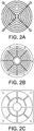
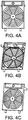
- FIGS. 2A-2C , 3A-3C and 4A-4C illustrate known fan covers that can be employed within an equipment rack environment. As shown, FIGS. 2A-2C illustrate typical grille-type fan covers. FIGS. 3A-3C illustrate perforated-type fan covers. FIGS. 4A-4C illustrate a fan cover that is used on existing equipment racks.
- the fan cover configured to be mounted on a housing of a fan module.
- the fan cover comprises a frame having an opening formed therein, a central hub positioned within the opening of the frame, and a plurality of spiral-shaped air guidance members that extend from the central hub to the frame. Gaps between the spiral-shaped air guidance members of the plurality of spiral-shaped air guidance members enable air to flow from the fan module through the fan cover.
- Embodiments of the fan cover further may include a plurality of projections extending from the frame.
- the plurality of projections each are received within a corresponding aperture formed in the housing of the fan module to align and receive the fan cover to the fan module.
- the plurality of projections may include four projections.
- Each spiral-shaped air guidance member may extend perpendicularly from the central hub and curves towards the frame at an angle with respect to the opening of the frame.
- Each spiral-shaped air guidance member may project above a plane defined by the frame.
- the spiral-shaped air guidance member may be helical in construction.
- Each spiral-shaped air guidance member may have a plurality of openings formed therein.
- a diameter of the opening of the frame may be larger than a fan vent of the fan module, and a diameter of the central hub may be smaller than a diameter of a fan motor of the fan module.
- the fan cover may be fabricated from plastic material. Each spiral-shaped air guidance member may be shaped to approximate a fan blade of the fan module.
- the fan cover may be configured to make a thermal source cooler.
- a fan module comprising a housing, an axial fan coupled to the housing, a motor coupled to the axial fan to drive a rotation of the axial fan, and a cover configured to be mounted on a housing of a fan module.
- the fan cover includes a frame having an opening formed therein, the frame being configured to be secured to the housing, a central hub positioned within the opening of the frame, and a plurality of spiral-shaped air guidance members that extend from the central hub to the frame. Gaps between the spiral-shaped air guidance members of the plurality of spiral-shaped air guidance members enable air to flow from the fan module through the fan cover.
- Embodiments of the fan module further may include a plurality of projections extending from the frame.
- the plurality of projections each are received within a corresponding aperture formed in the housing of the fan module to align and receive the fan cover to the fan module.
- the plurality of projections may include four projections.
- Each projection may include a shaft and a rivet head that is formed on the end of the shaft.
- Each spiral-shaped air guidance member may extend perpendicularly from the central hub and curves towards the frame at an angle with respect to the opening of the frame.
- Each spiral-shaped air guidance member may project above a plane defined by the frame.
- Each spiral-shaped air guidance member may have a plurality of openings formed therein.
- a diameter of the central hub is smaller than a diameter of the fan motor of the fan module.
- At least one embodiment of the present disclosure is directed a fan module having a fan cover that is used within equipment enclosures or racks of a data center.
- "enclosures” and “racks” are used to describe apparatus designed to support electronic equipment. Data centers are typically large rooms designed, in certain instances, to house hundreds of electronic equipment racks arranged in rows within the data center. "Enclosures” and “racks” are further used to describe apparatus designed to support cooling equipment used to provide strategic cooling within the data center. In some embodiments, "enclosures” and “racks” can support electronic equipment and cooling equipment.
- Embodiments of equipment racks and/or cooling racks embody fan modules, such as an exemplary fan module generally indicated at 10 shown in FIG. 5 , within the racks to move air within the racks.
- Each rack can be configured to employ multiple fan modules 10 within the rack environment.
- fan units are configured to draw air from the front of the rack to the back of the rack.
- the fan module 10 may be assembled and wired within the housing of the rack such that the fan module is removed by removing fasteners and sliding the fan module out of a receptacle formed in the housing of the rack.
- the electrical power provided to each fan module 10 may be connected and disconnected by a suitable connector, such as a blindmate connector.
- a controller may be configured to monitor the operation of the fan so as to predict the failure of a fan based on power draw variances of the fan.
- the controller is also configured to control the operation of the other working components of the rack.
- the fan module 10 includes a generally rectangular casing or housing, generally indicated at 12, that is configured to support the components of the fan module.
- the housing 12 includes an outer flange 14, an inner flange 16 and a cylindrical wall 18 that connects the outer flange and the inner flange.
- a support structure 20 is connected to the cylindrical wall 18 to support a motor and an axial fan of the fan module.
- the housing 12 can be fabricated from any number of materials, including, aluminum, steel (painted or galvanized), stainless steel, and plastic.
- the housing 12 of the fan module 10 can embody any size and shape depending on the intended use of the fan module.
- the fan module 10 further includes an axial fan, generally indicated at 22, having a motor 24 supported by the support structure 20, and a plurality of fan blades, each indicated at 26, that extend from a housing of the motor.
- the motor 24 is located in the central part of the axial fan 22 and is rotatably coupled to the support structure 20 of the housing, with the housing of the motor being fabricated from aluminum, steel, stainless steel, and plastic.
- the motor 24 includes a motor shaft to mount the axial fan. As shown, each blade 26 is mounted on the housing of the motor 24, with the blades being dynamically balanced to prevent unwanted vibration of the axial fan 22 module during operation.
- the blades 26 can be made from the same materials as the housing of the motor, e.g., aluminum, steel, stainless steel, glass- and carbon-fiber composites, and the like.
- the blades 26 can be secured to the housing of the motor 24 at different angles, which has a direct influence on the flow characteristics of the axial fan 22.
- the axial fan 22 is configured to rotate in one direction, but can be configured to be reversible to rotate in clockwise and counterclockwise directions.
- the motor 24 can includes several speed motor or a variable speed motor to vary a rate of rotation of the axial fan 22. For example, two-speed motors combine variable operating conditions and a lower operating cost.
- the fan module 10 further includes a fan cover, generally indicated at 30.
- the fan cover 30 is configured to be mounted on the housing 12 of the fan module 10.
- the fan cover 30 includes a frame 32 having a relatively large opening 34 formed therein.
- the frame 32 of the fan cover 30 can be fabricated from any number of materials, including, aluminum, steel, stainless steel, and plastic.
- the fan cover 30 is fabricated from plastic material, such as a polycarbonate-siloxane copolymer.
- the fan cover 30 further includes a central hub 36 positioned within the opening 34 of the frame 32 and a plurality of spiral-shaped air guidance members, each indicated at 38, that extend from the central hub to the frame.
- the fan cover 30 includes twelve spiral-shaped air guidance members 38; however, any number of air guidance members can be provided and fall within the scope of the present disclosure.
- the arrangement is such that gaps 40 between the spiral-shaped air guidance members 38 enable air to flow from the fan module 10 through the fan cover 30.
- Each spiral-shaped air guidance member 38 is shaped to approximate a fan blade of the fan module.
- the construction of the spiral-shaped air guidance members 38 facilitate the flow of air generated by the axial fan through the gaps 40 of the fan cover 30, thereby providing more effective thermal management of the space in which the fan module 10 operates.
- the fan cover 30 is configured to make a thermal source cooler, which will be described below.
- each spiral-shaped air guidance member 38 extends generally perpendicularly from the central hub 36 and curves towards an outer periphery of the frame 32 at an angle with respect to the opening 34 of the frame where the air guidance member is secured to the frame. As best shown in FIG. 9 , each spiral-shaped air guidance member 38 projects above a plane defined by the frame 32. As shown, the central hub 36 is elevated with respect to a plane defined by the frame 32 so that the spiral-shaped air guidance members curve upwardly in addition to curing to an outer periphery of the frame. In one embodiment, each spiral-shaped air guidance member 38 is helical in construction.
- each spiral-shaped air guidance member 38 has a plurality of openings, each indicated at 42, formed therein.
- each spiral-shaped guidance member 38 includes two rows or series of openings 42 that extend along a length of the air guidance member, with each guidance member having approximately 17 openings formed therein.
- any number of openings 42 or rows of openings can be provided to achieve improved airflow through the fan cover 10 described herein.
- These openings 42, along with the gaps 40 between the spiral-shaped air guidance members 38, further facilitate the flow of air generated by the axial fan 22 through the fan cover 30, while providing protection from a person's fingers being inserted into the fan module 10.
- the increased flow provided by the fan cover 30 is better understood with reference to FIGS. 14-17 , which are described below.
- the fan cover 30 is configured to be mounted on the housing 12 of the fan module 10.
- the fan cover 30 includes several, e.g., four, projections, each indicated at 44, which extend perpendicularly from the frame 32.
- each projection 44 includes a cylindrical shaft that is configured with a rivet head 46 to secure the fan cover 30 to the housing 12 of the fan module 10.
- the rivet head 46 is formed by applying a large current and high resistance to an end of the projection 44 with an electric pole.
- the housing 12 of the fan module 10 includes several, e.g., four, installation apertures 48, to receive the projections 44 of the fan cover 30.
- the outer flange 14 of the housing 12 has an aperture 48 provided at the four corners of the outer flange.
- the inner flange 16 is also provided with installation apertures to address the situation when the fan cover 30 is mounted on the other side of the fan module 10.
- Each projection 44 is received within a corresponding aperture 48 formed in the housing 12 of the fan module 10 to align and receive the fan cover 30 to the fan module. Once the projections 44 are inserted into their respective apertures 48, the rivet heads 46 are formed on the projections to secure the projections and the fan cover 30 to the housing 12 of the fan module 10.
- a diameter of the opening 34 of the frame 32 is larger than a fan vent of the fan module 10. Moreover, a diameter of the central hub 36 of the fan cover 30 is smaller than a diameter of the fan motor 24 of the fan module 10.
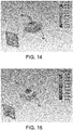
- FIGS. 14-17 the effectiveness of the fan cover 30 of the present disclosure as compared to prior art fan covers is represented.
- a thermal source e.g., a heat sink with an electronic package mounted thereon
- the electronic package is a 250 Watt thermal source.
- FIG. 14 illustrates a metal wire, grille-type fan cover.
- FIG. 15 illustrates a plastic grille-type fan cover.
- FIG. 16 illustrates a perforated-type, e.g., hex cut, fan cover.
- FIG. 17 illustrates a fan cover of an embodiment of the present disclosure.
- the fan cover described herein reduced the simulated temperature by more than two degrees Celsius as compared to the next effective fan cover, i.e., the perforated-type fan cover.
- the fan cover of an embodiment of the present disclosure makes the thermal source cooler, so as to improve thermal conditions within the equipment or cooling rack.
- references to "or” may be construed as inclusive so that any terms described using “or” may indicate any of a single, more than one, and all of the described terms. Any references to front and back, left and right, top and bottom, upper and lower, and vertical and horizontal are intended for convenience of description, not to limit the present systems and methods or their components to any one positional or spatial orientation.
Landscapes
- Engineering & Computer Science (AREA)
- General Engineering & Computer Science (AREA)
- Mechanical Engineering (AREA)
- Microelectronics & Electronic Packaging (AREA)
- Physics & Mathematics (AREA)
- Thermal Sciences (AREA)
- Computer Hardware Design (AREA)
- Geometry (AREA)
- Cooling Or The Like Of Electrical Apparatus (AREA)
- Structures Of Non-Positive Displacement Pumps (AREA)
Abstract
Description
- The present disclosure relates generally to the cooling systems used in a data center environment, and more particularly to a cooling rack fan module having an improved fan cover configured to improve thermal cooling of the cooling system.
- Equipment enclosures or racks for housing electronic equipment, such as data processing, networking and telecommunications equipment have been used for many years. Such racks are used to contain and to arrange the equipment in large data centers, as well as small wiring closets and equipment rooms. In certain embodiments, an equipment rack can be an open configuration and can be housed within a rack enclosure, although the enclosure may be included when referring to a rack. A standard rack typically includes front mounting rails to which multiple units of electronic equipment, such as servers, CPUs and telecommunication equipment, are mounted and stacked vertically within the rack. With the proliferation of the Internet, it is not uncommon for a data center to contain hundreds of these racks. Further, with the ever decreasing size of computer equipment, and in particular, computer servers and blades, the number of electrical devices mounted in each rack has been increasing, raising concerns about adequately cooling the equipment.
- Heat produced by rack-mounted equipment can have adverse effects on the performance, reliability and useful life of the equipment components. In particular, rack-mounted equipment, housed within an enclosure, may be vulnerable to heat build-up and hot spots produced within the confines of the enclosure during operation. The amount of heat generated by a rack of equipment is dependent on the amount of electrical power drawn by equipment in the rack during operation. In addition, users of electronic equipment may add, remove, and rearrange rack-mounted components as their needs change and new needs develop.
- There is a continuous need to improve the performance of the cooling within such environments, including increasing energy efficiency and air flow rate. Fan modules are used to cool electronic equipment, including semiconductors, in combination with heat sinks. Such a fan module typically includes a bladed fan driven by a motor at high rotational speeds, and can be positioned within an electronics equipment rack behind a door of the equipment rack. Such fans are also used on cooling racks.
FIGS. 1A-1C illustrate some well-known fan module configurations. - Such fan modules further include a fan cover to protect a person accessing the equipment rack from the high-speed rotating blades. Known fan covers include a grill fan cover, typically fabricated from metal or plastic, that is used to protect the person accessing the equipment rack from the fan blades. A shortcoming associated with most fan covers is that while the fan covers protect the person from placing fingers within the fan module, the fan cover blocks the flow of air generated by the bladed fan of the fan module. The openings can be increased but at the risk of failing to protect the person from the bladed fan of the fan module.
-
FIGS. 2A-2C ,3A-3C and4A-4C illustrate known fan covers that can be employed within an equipment rack environment. As shown,FIGS. 2A-2C illustrate typical grille-type fan covers.FIGS. 3A-3C illustrate perforated-type fan covers.FIGS. 4A-4C illustrate a fan cover that is used on existing equipment racks. - One aspect of the disclosure is directed to a fan cover configured to be mounted on a housing of a fan module. In one embodiment, the fan cover comprises a frame having an opening formed therein, a central hub positioned within the opening of the frame, and a plurality of spiral-shaped air guidance members that extend from the central hub to the frame. Gaps between the spiral-shaped air guidance members of the plurality of spiral-shaped air guidance members enable air to flow from the fan module through the fan cover.
- Embodiments of the fan cover further may include a plurality of projections extending from the frame. The plurality of projections each are received within a corresponding aperture formed in the housing of the fan module to align and receive the fan cover to the fan module. The plurality of projections may include four projections. Each spiral-shaped air guidance member may extend perpendicularly from the central hub and curves towards the frame at an angle with respect to the opening of the frame. Each spiral-shaped air guidance member may project above a plane defined by the frame. The spiral-shaped air guidance member may be helical in construction. Each spiral-shaped air guidance member may have a plurality of openings formed therein. A diameter of the opening of the frame may be larger than a fan vent of the fan module, and a diameter of the central hub may be smaller than a diameter of a fan motor of the fan module. The fan cover may be fabricated from plastic material. Each spiral-shaped air guidance member may be shaped to approximate a fan blade of the fan module. The fan cover may be configured to make a thermal source cooler.
- Another aspect of the present disclosure is directed to a fan module comprising a housing, an axial fan coupled to the housing, a motor coupled to the axial fan to drive a rotation of the axial fan, and a cover configured to be mounted on a housing of a fan module. In one embodiment, the fan cover includes a frame having an opening formed therein, the frame being configured to be secured to the housing, a central hub positioned within the opening of the frame, and a plurality of spiral-shaped air guidance members that extend from the central hub to the frame. Gaps between the spiral-shaped air guidance members of the plurality of spiral-shaped air guidance members enable air to flow from the fan module through the fan cover.
- Embodiments of the fan module further may include a plurality of projections extending from the frame. The plurality of projections each are received within a corresponding aperture formed in the housing of the fan module to align and receive the fan cover to the fan module. The plurality of projections may include four projections. Each projection may include a shaft and a rivet head that is formed on the end of the shaft. Each spiral-shaped air guidance member may extend perpendicularly from the central hub and curves towards the frame at an angle with respect to the opening of the frame. Each spiral-shaped air guidance member may project above a plane defined by the frame. Each spiral-shaped air guidance member may have a plurality of openings formed therein. A diameter of the central hub is smaller than a diameter of the fan motor of the fan module.
- Various aspects of at least one embodiment are discussed below with reference to the accompanying figures, which are not intended to be drawn to scale. Where technical features in the figures, detailed description or any claim are followed by references signs, the reference signs have been included for the sole purpose of increasing the intelligibility of the figures, detailed description, and claims. Accordingly, neither the reference signs nor their absence are intended to have any limiting effect on the scope of any claim elements. In the figures, each identical or nearly identical component that is illustrated in various figures is represented by a like numeral. For purposes of clarity, not every component may be labeled in every figure. The figures are provided for the purposes of illustration and explanation and are not intended as a definition of the limits of the disclosure. In the figures:
-
FIGS. 1A-1C are views of known fan module configurations; -
FIGS. 2A-2C are front views of known grille-type fan covers; -
FIGS. 3A-3C are front views of known perforated-type fan covers; -
FIGS. 4A-4C are views of a known fan cover for an equipment rack; -
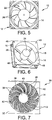
FIG. 5 is a front perspective view of a fan module; -
FIG. 6 is a front perspective view of a housing of the fan module; -
FIG. 7 is a front perspective view of a fan cover of an embodiment of the present disclosure; -
FIG. 8 is a back perspective view of the fan cover; -
FIG. 9 is a side view of the fan cover; -
FIGS. 10-13 are views showing features provided to mount the fan cover on the fan module; -
FIGS. 14-16 are graphical representations of thermal effects of prior art fan covers proximate a heat sink having an electronic package; and -
FIG. 17 is a graphical representation of the thermal effect of the fan cover of embodiments of the present disclosure proximate a heat sink having an electronic package. - At least one embodiment of the present disclosure is directed a fan module having a fan cover that is used within equipment enclosures or racks of a data center. As used herein, "enclosures" and "racks" are used to describe apparatus designed to support electronic equipment. Data centers are typically large rooms designed, in certain instances, to house hundreds of electronic equipment racks arranged in rows within the data center. "Enclosures" and "racks" are further used to describe apparatus designed to support cooling equipment used to provide strategic cooling within the data center. In some embodiments, "enclosures" and "racks" can support electronic equipment and cooling equipment.
- Embodiments of equipment racks and/or cooling racks embody fan modules, such as an exemplary fan module generally indicated at 10 shown in
FIG. 5 , within the racks to move air within the racks. Each rack can be configured to employmultiple fan modules 10 within the rack environment. For example, within an equipment rack and/or a cooling rack, fan units are configured to draw air from the front of the rack to the back of the rack. In one embodiment, thefan module 10 may be assembled and wired within the housing of the rack such that the fan module is removed by removing fasteners and sliding the fan module out of a receptacle formed in the housing of the rack. The electrical power provided to eachfan module 10 may be connected and disconnected by a suitable connector, such as a blindmate connector. The arrangement is such that thefan modules 10 are "hot swappable" based on voltage requirements as well as their easy removal from the receptacle and the blindmate connector. In some embodiments, a controller may be configured to monitor the operation of the fan so as to predict the failure of a fan based on power draw variances of the fan. The controller is also configured to control the operation of the other working components of the rack. - As shown in
FIGS. 5 and 6 , thefan module 10 includes a generally rectangular casing or housing, generally indicated at 12, that is configured to support the components of the fan module. As best shown inFIG. 6 , thehousing 12 includes anouter flange 14, aninner flange 16 and acylindrical wall 18 that connects the outer flange and the inner flange. Asupport structure 20 is connected to thecylindrical wall 18 to support a motor and an axial fan of the fan module. Thehousing 12 can be fabricated from any number of materials, including, aluminum, steel (painted or galvanized), stainless steel, and plastic. In addition, although rectangular in shape, thehousing 12 of thefan module 10 can embody any size and shape depending on the intended use of the fan module. - The
fan module 10 further includes an axial fan, generally indicated at 22, having amotor 24 supported by thesupport structure 20, and a plurality of fan blades, each indicated at 26, that extend from a housing of the motor. Themotor 24 is located in the central part of theaxial fan 22 and is rotatably coupled to thesupport structure 20 of the housing, with the housing of the motor being fabricated from aluminum, steel, stainless steel, and plastic. Themotor 24 includes a motor shaft to mount the axial fan. As shown, eachblade 26 is mounted on the housing of themotor 24, with the blades being dynamically balanced to prevent unwanted vibration of theaxial fan 22 module during operation. Theblades 26 can be made from the same materials as the housing of the motor, e.g., aluminum, steel, stainless steel, glass- and carbon-fiber composites, and the like. Theblades 26 can be secured to the housing of themotor 24 at different angles, which has a direct influence on the flow characteristics of theaxial fan 22. Theaxial fan 22 is configured to rotate in one direction, but can be configured to be reversible to rotate in clockwise and counterclockwise directions. Themotor 24 can includes several speed motor or a variable speed motor to vary a rate of rotation of theaxial fan 22. For example, two-speed motors combine variable operating conditions and a lower operating cost. - Referring to
FIGS. 7-9 , thefan module 10 further includes a fan cover, generally indicated at 30. As will be described in greater detail below, thefan cover 30 is configured to be mounted on thehousing 12 of thefan module 10. In one embodiment, thefan cover 30 includes aframe 32 having a relativelylarge opening 34 formed therein. As with thehousing 12 of thefan module 10, theframe 32 of thefan cover 30 can be fabricated from any number of materials, including, aluminum, steel, stainless steel, and plastic. However, preferably thefan cover 30 is fabricated from plastic material, such as a polycarbonate-siloxane copolymer. - The
fan cover 30 further includes acentral hub 36 positioned within theopening 34 of theframe 32 and a plurality of spiral-shaped air guidance members, each indicated at 38, that extend from the central hub to the frame. In the shown embodiment, thefan cover 30 includes twelve spiral-shapedair guidance members 38; however, any number of air guidance members can be provided and fall within the scope of the present disclosure. The arrangement is such thatgaps 40 between the spiral-shapedair guidance members 38 enable air to flow from thefan module 10 through thefan cover 30. Each spiral-shapedair guidance member 38 is shaped to approximate a fan blade of the fan module. The construction of the spiral-shapedair guidance members 38 facilitate the flow of air generated by the axial fan through thegaps 40 of thefan cover 30, thereby providing more effective thermal management of the space in which thefan module 10 operates. Thefan cover 30 is configured to make a thermal source cooler, which will be described below. - In a certain embodiment, each spiral-shaped
air guidance member 38 extends generally perpendicularly from thecentral hub 36 and curves towards an outer periphery of theframe 32 at an angle with respect to theopening 34 of the frame where the air guidance member is secured to the frame. As best shown inFIG. 9 , each spiral-shapedair guidance member 38 projects above a plane defined by theframe 32. As shown, thecentral hub 36 is elevated with respect to a plane defined by theframe 32 so that the spiral-shaped air guidance members curve upwardly in addition to curing to an outer periphery of the frame. In one embodiment, each spiral-shapedair guidance member 38 is helical in construction. - As shown in
FIGS. 7 and8 , each spiral-shapedair guidance member 38 has a plurality of openings, each indicated at 42, formed therein. In the shown embodiment, each spiral-shapedguidance member 38 includes two rows or series ofopenings 42 that extend along a length of the air guidance member, with each guidance member having approximately 17 openings formed therein. It should be noted that any number ofopenings 42 or rows of openings can be provided to achieve improved airflow through thefan cover 10 described herein. Theseopenings 42, along with thegaps 40 between the spiral-shapedair guidance members 38, further facilitate the flow of air generated by theaxial fan 22 through thefan cover 30, while providing protection from a person's fingers being inserted into thefan module 10. The increased flow provided by thefan cover 30 is better understood with reference toFIGS. 14-17 , which are described below. - The
fan cover 30 is configured to be mounted on thehousing 12 of thefan module 10. In one embodiment, with reference toFIGS. 10-13 , thefan cover 30 includes several, e.g., four, projections, each indicated at 44, which extend perpendicularly from theframe 32. As shown best inFIG. 13 , eachprojection 44 includes a cylindrical shaft that is configured with arivet head 46 to secure thefan cover 30 to thehousing 12 of thefan module 10. In one embodiment, therivet head 46 is formed by applying a large current and high resistance to an end of theprojection 44 with an electric pole. Thehousing 12 of thefan module 10 includes several, e.g., four,installation apertures 48, to receive theprojections 44 of thefan cover 30. In the shown embodiment, theouter flange 14 of thehousing 12 has anaperture 48 provided at the four corners of the outer flange. Theinner flange 16 is also provided with installation apertures to address the situation when thefan cover 30 is mounted on the other side of thefan module 10. Eachprojection 44 is received within a correspondingaperture 48 formed in thehousing 12 of thefan module 10 to align and receive thefan cover 30 to the fan module. Once theprojections 44 are inserted into theirrespective apertures 48, the rivet heads 46 are formed on the projections to secure the projections and thefan cover 30 to thehousing 12 of thefan module 10. - In one embodiment, a diameter of the
opening 34 of theframe 32 is larger than a fan vent of thefan module 10. Moreover, a diameter of thecentral hub 36 of thefan cover 30 is smaller than a diameter of thefan motor 24 of thefan module 10. - Referring to
FIGS. 14-17 , the effectiveness of thefan cover 30 of the present disclosure as compared to prior art fan covers is represented. In these figures, a thermal source, e.g., a heat sink with an electronic package mounted thereon, is subjected to airflow provided by different types of fan covers. In the simulations, the electronic package is a 250 Watt thermal source.FIG. 14 illustrates a metal wire, grille-type fan cover.FIG. 15 illustrates a plastic grille-type fan cover.FIG. 16 illustrates a perforated-type, e.g., hex cut, fan cover.FIG. 17 illustrates a fan cover of an embodiment of the present disclosure. In the simulation, the fan cover described herein reduced the simulated temperature by more than two degrees Celsius as compared to the next effective fan cover, i.e., the perforated-type fan cover. The fan cover of an embodiment of the present disclosure makes the thermal source cooler, so as to improve thermal conditions within the equipment or cooling rack. - It is to be appreciated that embodiments of the devices and methods discussed herein are not limited in application to the details of construction and the arrangement of components set forth in the following description or illustrated in the accompanying drawings. The devices and methods are capable of implementation in other embodiments and of being practiced or of being carried out in various ways. Examples of specific implementations are provided herein for illustrative purposes only and are not intended to be limiting. In particular, acts, elements and features discussed in connection with any one or more embodiments are not intended to be excluded from a similar role in any other embodiments.
- Also, the phraseology and terminology used herein is for the purpose of description and should not be regarded as limiting. Any references to embodiments or elements or acts of the systems and methods herein referred to in the singular may also embrace embodiments including a plurality of these elements, and any references in plural to any embodiment or element or act herein may also embrace embodiments including only a single element. References in the singular or plural form are not intended to limit the presently disclosed systems or methods, their components, acts, or elements. The use herein of "including," "comprising," "having," "containing," "involving," and variations thereof is meant to encompass the items listed thereafter and equivalents thereof as well as additional items. References to "or" may be construed as inclusive so that any terms described using "or" may indicate any of a single, more than one, and all of the described terms. Any references to front and back, left and right, top and bottom, upper and lower, and vertical and horizontal are intended for convenience of description, not to limit the present systems and methods or their components to any one positional or spatial orientation.
- Having thus described several aspects of at least one embodiment, it is to be appreciated various alterations, modifications, and improvements will readily occur to those skilled in the art. Such alterations, modifications, and improvements are intended to be part of this disclosure and are intended to be within the scope of the disclosure. Accordingly, the foregoing description and drawings are by way of example only, and the scope of the disclosure should be determined from proper construction of the appended claims, and their equivalents.
Claims (14)
- A fan cover configured to be mounted on a housing of a fan module, the fan cover comprising:a frame having an opening formed therein;a central hub positioned within the opening of the frame; anda plurality of spiral-shaped air guidance members that extend from the central hub to the frame,wherein gaps between the spiral-shaped air guidance members of the plurality of spiral-shaped air guidance members enable air to flow from the fan module through the fan cover.
- The fan cover of claim 1, wherein each spiral-shaped air guidance member extends perpendicularly from the central hub and curves towards the frame at an angle with respect to the opening of the frame.
- The fan cover of claim 2, wherein each spiral-shaped air guidance member projects above a plane defined by the frame.
- The fan cover of claim 3, wherein the spiral-shaped air guidance member is helical in construction.
- The fan cover of claim 4, wherein each spiral-shaped air guidance member has a plurality of openings formed therein.
- The fan cover of claim 1, further comprising a plurality of projections extending from the frame, the plurality of projections each being received within a corresponding aperture formed in the housing of the fan module to align and receive the fan cover to the fan module.
- The fan cover of claim 6, wherein the plurality of projections includes four projections.
- The fan cover of claim 1, wherein a diameter of the opening of the frame is larger than a fan vent of the fan module.
- The fan cover of claim 1, wherein a diameter of the central hub is smaller than a diameter of a fan motor of the fan module.
- The fan cover of claim 1, wherein the fan cover is fabricated from plastic material.
- The fan cover of claim 1, wherein each spiral-shaped air guidance member is shaped to approximate a fan blade of the fan module.
- The fan cover of claim 1, wherein the fan cover is configured to make a thermal source cooler.
- A fan module comprising:a housing;an axial fan coupled to the housing;a motor coupled to the axial fan to drive a rotation of the axial fan; anda cover configured to be mounted on a housing of a fan module
- The fan module of claim 13, wherein each projection includes a shaft and a rivet head that is formed on the end of the shaft.
Applications Claiming Priority (1)
| Application Number | Priority Date | Filing Date | Title |
|---|---|---|---|
| CN201910152107.0A CN111622992A (en) | 2019-02-28 | 2019-02-28 | Fan cover |
Publications (1)
| Publication Number | Publication Date |
|---|---|
| EP3703478A1 true EP3703478A1 (en) | 2020-09-02 |
Family
ID=69902973
Family Applications (1)
| Application Number | Title | Priority Date | Filing Date |
|---|---|---|---|
| EP20159324.1A Withdrawn EP3703478A1 (en) | 2019-02-28 | 2020-02-25 | Fan cover |
Country Status (3)
| Country | Link |
|---|---|
| US (1) | US11280352B2 (en) |
| EP (1) | EP3703478A1 (en) |
| CN (1) | CN111622992A (en) |
Families Citing this family (4)
| Publication number | Priority date | Publication date | Assignee | Title |
|---|---|---|---|---|
| KR102802862B1 (en) * | 2020-03-02 | 2025-04-30 | 엘지전자 주식회사 | Portable air caring device |
| US11982294B2 (en) | 2022-08-02 | 2024-05-14 | Schneider Electric It Corporation | System and method for replacing a fan in an energized state |
| US12055159B2 (en) * | 2022-09-26 | 2024-08-06 | ZT Group Int'l, Inc. | Fan guard |
| CN117874500B (en) * | 2024-03-13 | 2024-06-07 | 广东工业大学 | Multi-view fusion offshore wind farm cluster power prediction method |
Citations (2)
| Publication number | Priority date | Publication date | Assignee | Title |
|---|---|---|---|---|
| US20030026691A1 (en) * | 2001-08-01 | 2003-02-06 | Wen-Shi Huang | Composite heat-dissipating system and its used fan guard with additional supercharging function |
| US20090101315A1 (en) * | 2007-10-17 | 2009-04-23 | Liang-Ho Cheng | Turbo-guiding type cooling apparatus |
Family Cites Families (29)
| Publication number | Priority date | Publication date | Assignee | Title |
|---|---|---|---|---|
| JPS6141886U (en) | 1984-08-21 | 1986-03-17 | 株式会社 日本計器製作所 | Juan Motor |
| TW488497U (en) * | 1999-03-02 | 2002-05-21 | Delta Electronics Inc | Supercharged fan stator for wind diversion |
| US7008180B2 (en) * | 2002-06-28 | 2006-03-07 | Seiko Epson Corporation | Axial-flow fan and projector provided with the same |
| JP2004143983A (en) * | 2002-10-23 | 2004-05-20 | Matsushita Electric Ind Co Ltd | Fan cover, fan cover fixing method and equipment |
| US7118333B2 (en) | 2002-11-22 | 2006-10-10 | Nidec Corporation | Electric cooling fan and case of electronic or electric device |
| CA2607971A1 (en) * | 2005-05-12 | 2006-11-16 | Advantec Australasia Pty. Limited | Vent and grilles |
| TW200801346A (en) * | 2006-06-12 | 2008-01-01 | geng-wen Ceng | Fan device using static fan blades and dynamic fan blades to change pressure |
| WO2008123846A1 (en) * | 2007-04-03 | 2008-10-16 | Carrier Corporation | Outlet guide vanes for axial flow fans |
| DE102008044505B4 (en) * | 2008-09-08 | 2010-07-01 | Friedrich-Alexander-Universität Erlangen-Nürnberg | centrifugal compressors |
| US20130000493A1 (en) | 2010-05-18 | 2013-01-03 | Takashi Watanabe | Automatic bread machine |
| FR2989999B1 (en) * | 2012-04-26 | 2016-01-01 | Sdmo Ind | COOLING DEVICE COMPRISING AN AXIAL FAN WITH CENTRAL FLOW RECTIFICATION AND CORRESPONDING ELECTROGEN GROUP. |
| GB2501725B (en) * | 2012-04-30 | 2019-04-10 | Nidec Control Techniques Ltd | Fan guard |
| US9151294B2 (en) * | 2012-07-18 | 2015-10-06 | Bel'air International Group Ltd. | Fan device with fluidic air function |
| TR201314979A2 (en) * | 2013-12-19 | 2015-07-21 | Arcelik Lg Klima Sanayi Ve Ticaret Anonim Sirketi | A fan connection system. |
| JP2016017458A (en) * | 2014-07-08 | 2016-02-01 | ダイキン工業株式会社 | Fan housing and blower unit |
| TWM497203U (en) * | 2014-10-15 | 2015-03-11 | Zhen-Ming Su | Improved internal-spinning swirl cyclone wind scooper and fan device including the same |
| US10267234B2 (en) * | 2015-07-06 | 2019-04-23 | Dresser-Rand Company | Motive air conditioning system for gas turbines |
| CN106224293B (en) * | 2016-09-30 | 2019-08-27 | 广东美的环境电器制造有限公司 | Diffuser, power system and bladeless fan |
| RU169892U1 (en) * | 2017-01-09 | 2017-04-05 | Общество с ограниченной ответственностью "Научно исследовательский институт технических систем "Пилот" | Hydrodynamic device of an electric centrifugal pump for magnetic processing of well fluid |
| CN106837832B (en) * | 2017-01-22 | 2019-03-22 | 佛山市顺德区新双岭机电科技有限公司 | A kind of novel portable electric fan |
| CN106930977A (en) * | 2017-03-17 | 2017-07-07 | 中国大唐集团科技工程有限公司 | A kind of direct-cooled noise reduction axial flow blower |
| CN107339265B (en) * | 2017-07-31 | 2019-08-23 | 广东美的环境电器制造有限公司 | Fan with cooling device |
| JP6363811B1 (en) * | 2017-09-29 | 2018-07-25 | アイリスオーヤマ株式会社 | Circulator |
| CN108194394A (en) * | 2018-02-07 | 2018-06-22 | 广东美的环境电器制造有限公司 | Preceding screen panel of fan and fan that has it |
| CN109139570B (en) * | 2018-08-24 | 2025-10-31 | 珠海格力电器股份有限公司 | Air inlet grille and fan |
| CN109340179B (en) * | 2018-11-27 | 2024-05-10 | 星德胜科技(苏州)股份有限公司 | High-strength centrifugal impeller and motor suitable for dust collector |
| JP2020109258A (en) * | 2018-12-28 | 2020-07-16 | 日本電産株式会社 | Air blowing device |
| GB201911291D0 (en) * | 2019-08-07 | 2019-09-18 | Rolls Royce Plc | Aerofoil |
| US20210062816A1 (en) * | 2019-08-28 | 2021-03-04 | Pax Scientific, Inc. | Fan assembly |
-
2019
- 2019-02-28 CN CN201910152107.0A patent/CN111622992A/en active Pending
-
2020
- 2020-02-25 EP EP20159324.1A patent/EP3703478A1/en not_active Withdrawn
- 2020-02-26 US US16/801,719 patent/US11280352B2/en not_active Expired - Fee Related
Patent Citations (2)
| Publication number | Priority date | Publication date | Assignee | Title |
|---|---|---|---|---|
| US20030026691A1 (en) * | 2001-08-01 | 2003-02-06 | Wen-Shi Huang | Composite heat-dissipating system and its used fan guard with additional supercharging function |
| US20090101315A1 (en) * | 2007-10-17 | 2009-04-23 | Liang-Ho Cheng | Turbo-guiding type cooling apparatus |
Also Published As
| Publication number | Publication date |
|---|---|
| US11280352B2 (en) | 2022-03-22 |
| CN111622992A (en) | 2020-09-04 |
| US20200277969A1 (en) | 2020-09-03 |
Similar Documents
| Publication | Publication Date | Title |
|---|---|---|
| US11280352B2 (en) | Fan cover | |
| US6813149B2 (en) | High capacity air-cooling systems for electronic apparatus and associated methods | |
| CN102484956B (en) | Passively cooled enclosure system and method for electronic devices | |
| US11197394B2 (en) | Protective louver assembly for air-moving assembly | |
| US10271460B2 (en) | Server system | |
| US8451605B2 (en) | Enclosure of electronic apparatus | |
| US6462944B1 (en) | Computer cabinet cooling system | |
| EP2983461B1 (en) | Cabinet structure and container data centre thereof | |
| US7400501B2 (en) | Method and apparatus for acoustic noise reduction in a computer system having a vented cover | |
| US6437980B1 (en) | Low profile high density rack mountable enclosure with superior cooling and highly accessible re-configurable components | |
| US9049802B2 (en) | Apparatus for receiving servers | |
| US20160095257A1 (en) | Locking louver assembly for air-moving assembly | |
| WO2001078479A2 (en) | Cooling system and method for high density electronics enclosure | |
| US20050231909A1 (en) | Chassis air guide thermal cooling solution | |
| WO2007043119A1 (en) | Fan device | |
| US9690338B2 (en) | Electronic device with cooling facility | |
| US20130108431A1 (en) | Fan assembly | |
| EP3068204A1 (en) | Unit device | |
| CN102339093A (en) | Server | |
| JP5316665B2 (en) | Fan device | |
| JP6775567B2 (en) | Cooling system and fan components to provide streamlined airflow | |
| JP5516629B2 (en) | Fan device | |
| JP5892122B2 (en) | Fan device and electronic device | |
| EP3432308A1 (en) | Modular ducting solution |
Legal Events
| Date | Code | Title | Description |
|---|---|---|---|
| PUAI | Public reference made under article 153(3) epc to a published international application that has entered the european phase |
Free format text: ORIGINAL CODE: 0009012 |
|
| STAA | Information on the status of an ep patent application or granted ep patent |
Free format text: STATUS: THE APPLICATION HAS BEEN PUBLISHED |
|
| AK | Designated contracting states |
Kind code of ref document: A1 Designated state(s): AL AT BE BG CH CY CZ DE DK EE ES FI FR GB GR HR HU IE IS IT LI LT LU LV MC MK MT NL NO PL PT RO RS SE SI SK SM TR |
|
| AX | Request for extension of the european patent |
Extension state: BA ME |
|
| STAA | Information on the status of an ep patent application or granted ep patent |
Free format text: STATUS: REQUEST FOR EXAMINATION WAS MADE |
|
| 17P | Request for examination filed |
Effective date: 20210127 |
|
| RBV | Designated contracting states (corrected) |
Designated state(s): AL AT BE BG CH CY CZ DE DK EE ES FI FR GB GR HR HU IE IS IT LI LT LU LV MC MK MT NL NO PL PT RO RS SE SI SK SM TR |
|
| REG | Reference to a national code |
Ref country code: DE Ref legal event code: R079 Free format text: PREVIOUS MAIN CLASS: H05K0007200000 Ipc: F04D0025060000 |
|
| GRAP | Despatch of communication of intention to grant a patent |
Free format text: ORIGINAL CODE: EPIDOSNIGR1 |
|
| STAA | Information on the status of an ep patent application or granted ep patent |
Free format text: STATUS: GRANT OF PATENT IS INTENDED |
|
| RIC1 | Information provided on ipc code assigned before grant |
Ipc: H05K 7/20 20060101ALI20220329BHEP Ipc: F04D 29/70 20060101ALI20220329BHEP Ipc: F04D 29/00 20060101ALI20220329BHEP Ipc: F04D 25/06 20060101AFI20220329BHEP |
|
| INTG | Intention to grant announced |
Effective date: 20220428 |
|
| STAA | Information on the status of an ep patent application or granted ep patent |
Free format text: STATUS: THE APPLICATION IS DEEMED TO BE WITHDRAWN |
|
| 18D | Application deemed to be withdrawn |
Effective date: 20220909 |