EP3703278A1 - Optical transmission device and optical transmission method - Google Patents
Optical transmission device and optical transmission method Download PDFInfo
- Publication number
- EP3703278A1 EP3703278A1 EP18870817.6A EP18870817A EP3703278A1 EP 3703278 A1 EP3703278 A1 EP 3703278A1 EP 18870817 A EP18870817 A EP 18870817A EP 3703278 A1 EP3703278 A1 EP 3703278A1
- Authority
- EP
- European Patent Office
- Prior art keywords
- signal
- optical transmission
- control signal
- optical
- control
- Prior art date
- Legal status (The legal status is an assumption and is not a legal conclusion. Google has not performed a legal analysis and makes no representation as to the accuracy of the status listed.)
- Withdrawn
Links
- 230000003287 optical effect Effects 0.000 title claims abstract description 263
- 230000005540 biological transmission Effects 0.000 title claims abstract description 143
- 238000000034 method Methods 0.000 title claims description 42
- 230000004044 response Effects 0.000 claims abstract description 168
- 230000007274 generation of a signal involved in cell-cell signaling Effects 0.000 claims abstract description 37
- 238000000605 extraction Methods 0.000 claims abstract description 17
- 230000005284 excitation Effects 0.000 claims description 20
- 230000035945 sensitivity Effects 0.000 abstract description 8
- 239000000284 extract Substances 0.000 abstract description 4
- 238000010586 diagram Methods 0.000 description 17
- 230000007423 decrease Effects 0.000 description 6
- 238000006243 chemical reaction Methods 0.000 description 4
- 238000001228 spectrum Methods 0.000 description 4
- 230000000694 effects Effects 0.000 description 3
- 230000008859 change Effects 0.000 description 2
- 230000006870 function Effects 0.000 description 2
- 238000012544 monitoring process Methods 0.000 description 2
- 239000013307 optical fiber Substances 0.000 description 2
- 238000001069 Raman spectroscopy Methods 0.000 description 1
- 230000009471 action Effects 0.000 description 1
- 230000003321 amplification Effects 0.000 description 1
- 230000008901 benefit Effects 0.000 description 1
- 230000008033 biological extinction Effects 0.000 description 1
- 230000004048 modification Effects 0.000 description 1
- 238000012986 modification Methods 0.000 description 1
- 238000003199 nucleic acid amplification method Methods 0.000 description 1
- 230000008569 process Effects 0.000 description 1
- 239000004065 semiconductor Substances 0.000 description 1
Images



Classifications
-
- H—ELECTRICITY
- H04—ELECTRIC COMMUNICATION TECHNIQUE
- H04B—TRANSMISSION
- H04B10/00—Transmission systems employing electromagnetic waves other than radio-waves, e.g. infrared, visible or ultraviolet light, or employing corpuscular radiation, e.g. quantum communication
- H04B10/29—Repeaters
- H04B10/291—Repeaters in which processing or amplification is carried out without conversion of the main signal from optical form
- H04B10/293—Signal power control
-
- H—ELECTRICITY
- H04—ELECTRIC COMMUNICATION TECHNIQUE
- H04B—TRANSMISSION
- H04B10/00—Transmission systems employing electromagnetic waves other than radio-waves, e.g. infrared, visible or ultraviolet light, or employing corpuscular radiation, e.g. quantum communication
- H04B10/07—Arrangements for monitoring or testing transmission systems; Arrangements for fault measurement of transmission systems
- H04B10/075—Arrangements for monitoring or testing transmission systems; Arrangements for fault measurement of transmission systems using an in-service signal
- H04B10/077—Arrangements for monitoring or testing transmission systems; Arrangements for fault measurement of transmission systems using an in-service signal using a supervisory or additional signal
- H04B10/0773—Network aspects, e.g. central monitoring of transmission parameters
-
- H—ELECTRICITY
- H04—ELECTRIC COMMUNICATION TECHNIQUE
- H04B—TRANSMISSION
- H04B10/00—Transmission systems employing electromagnetic waves other than radio-waves, e.g. infrared, visible or ultraviolet light, or employing corpuscular radiation, e.g. quantum communication
- H04B10/07—Arrangements for monitoring or testing transmission systems; Arrangements for fault measurement of transmission systems
- H04B10/075—Arrangements for monitoring or testing transmission systems; Arrangements for fault measurement of transmission systems using an in-service signal
- H04B10/077—Arrangements for monitoring or testing transmission systems; Arrangements for fault measurement of transmission systems using an in-service signal using a supervisory or additional signal
-
- H—ELECTRICITY
- H04—ELECTRIC COMMUNICATION TECHNIQUE
- H04B—TRANSMISSION
- H04B10/00—Transmission systems employing electromagnetic waves other than radio-waves, e.g. infrared, visible or ultraviolet light, or employing corpuscular radiation, e.g. quantum communication
- H04B10/07—Arrangements for monitoring or testing transmission systems; Arrangements for fault measurement of transmission systems
- H04B10/075—Arrangements for monitoring or testing transmission systems; Arrangements for fault measurement of transmission systems using an in-service signal
- H04B10/077—Arrangements for monitoring or testing transmission systems; Arrangements for fault measurement of transmission systems using an in-service signal using a supervisory or additional signal
- H04B10/0777—Monitoring line amplifier or line repeater equipment
-
- H—ELECTRICITY
- H04—ELECTRIC COMMUNICATION TECHNIQUE
- H04J—MULTIPLEX COMMUNICATION
- H04J14/00—Optical multiplex systems
- H04J14/02—Wavelength-division multiplex systems
- H04J14/0227—Operation, administration, maintenance or provisioning [OAMP] of WDM networks, e.g. media access, routing or wavelength allocation
-
- H—ELECTRICITY
- H04—ELECTRIC COMMUNICATION TECHNIQUE
- H04B—TRANSMISSION
- H04B2210/00—Indexing scheme relating to optical transmission systems
- H04B2210/07—Monitoring an optical transmission system using a supervisory signal
- H04B2210/074—Monitoring an optical transmission system using a supervisory signal using a superposed, over-modulated signal
-
- H—ELECTRICITY
- H04—ELECTRIC COMMUNICATION TECHNIQUE
- H04B—TRANSMISSION
- H04B2210/00—Indexing scheme relating to optical transmission systems
- H04B2210/07—Monitoring an optical transmission system using a supervisory signal
- H04B2210/075—Monitoring an optical transmission system using a supervisory signal using a pilot tone
-
- H—ELECTRICITY
- H04—ELECTRIC COMMUNICATION TECHNIQUE
- H04B—TRANSMISSION
- H04B2210/00—Indexing scheme relating to optical transmission systems
- H04B2210/07—Monitoring an optical transmission system using a supervisory signal
- H04B2210/078—Monitoring an optical transmission system using a supervisory signal using a separate wavelength
Definitions
- the present invention relates to an optical transmission device and an optical transmission method, and particularly relates to an optical transmission device and an optical transmission method that output a response signal according to a received control signal.
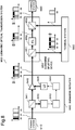
- Fig. 8 is a block diagram illustrating a configuration of a general submarine optical transmission system 900.
- the submarine optical transmission system 900 includes terminal stations 910, 920, and 930 located on land, a submarine repeater 940, and a submarine splitting device 950.
- the submarine repeater 940 receives an optical signal acquired by wavelength-multiplexing a control signal S0 and main signals S2 and S3 from the terminal station 910.
- the control signal S0 and the main signals S2 and S3 have wavelength bands different from one another.
- spectra of the control signal S0 and the main signals S2 to S4 of each unit on a transmission path are also illustrated in a diagram with a vertical axis as amplitude and a horizontal axis as wavelength.
- the control signal S0 is a signal for controlling the submarine repeater 940.
- the main signal S2 is a signal sent from the terminal station 910 to the terminal station 920.
- the main signal S3 is a signal sent from the terminal station 910 to the terminal station 930.
- WDM wavelength division multiplexed
- the submarine repeater 940 includes an optical coupler 941, an optical receiver 942, a control unit 943, a drive unit 944, a laser diode (LD) 945, and an optical amplifier 946.
- the optical coupler 941 splits the control signal S0 and the main signals S2 and S3, and outputs the control signal S0 and the main signals S2 and S3 to the optical receiver 942 and the optical amplifier 946.
- the optical receiver 942 performs optical-electrical (O/E) conversion on the control signal S0.
- the control unit 943 processes the control signal, and generates a response signal, based on a processing result.
- the optical amplifier 946 amplifies the control signal S0 and the main signals S2 and S3 split by the optical coupler 941.
- the LD 945 generates excitation light of the optical amplifier 946.
- the drive unit 944 modulates an amplitude of a drive current of the LD 945, based on the response signal generated by the control unit 943. In this way, a WDM signal including the control signal S0 and the main signals S2 and S3 input to the optical amplifier 946 is subjected to the amplitude modulation.
- a black region in the diagram indicating the spectrum of each of the signals in Fig. 8 schematically indicates the amplitude modulation of the WDM signal.
- the submarine splitting device 950 includes optical couplers 951 and 953 and an optical filter (FIL) 952.
- the optical coupler 951 splits the WDM signal output from the optical amplifier 946 of the submarine repeater 940, and outputs the WDM signals to the terminal station 930 and the optical filter 952.
- the terminal station 930 selects the main signal S3 being a signal addressed to the terminal station 930 from the received control signal S0 and the received main signals S2 and S3, and demodulates the main signal S3.
- the terminal station 930 sends a main signal S4 addressed to the terminal station 920.
- the main signal S4 is a signal having the same wavelength band as that of the main signal S3.
- the optical filter 952 blocks a wavelength range of the main signal S3.
- the optical coupler 953 outputs, to the terminal station 920, the WDM signal acquired by combining the control signal S0 and the main signal S2 that are transmitted from the terminal station 910 with the main signal S4 transmitted from the terminal station 930.
- the terminal station 920 can receive the main signals S2 and S4, and can also extract the response signal generated by the control unit 943 from an amplitude change in the control signal S0 and the main signal S2.
- PTL 1 describes a configuration in which a Raman amplification relay device generates a response signal with respect to a control signal, and sends the response signal to another terminal station.
- PTLs 2 and 3 describe a technique for monitoring an optical repeater by using monitoring signal light.
- the drive unit 944 controls excitation light power of the optical amplifier 946 by causing a fluctuation in drive current of the LD 945 by a response signal.
- the response signal is superimposed on light output power of the optical amplifier 946.
- an amplitude of the optical signal (S0, S2, and S3) included in the whole band that passes through the optical amplifier 946 is modulated based on the response signal. Therefore, when a modulation degree of the response signal is increased by increasing an amount of fluctuation in drive current of the LD 945, a transmission characteristic deteriorates due to an increase in amplitude fluctuation of the main signal, and thus the modulation degree of the response signal cannot be increased much.
- the WDM signal output from the submarine repeater 940 passes through the submarine splitting device 950 and is transmitted to the terminal station 920, the main signal S3 is blocked by the optical filter 952, and the main signal S4 that does not include a component of the response signal is multiplexed by the optical coupler 953.
- the modulation degree of the response signal decreases during demodulation of the response signal based on the WDM signal received by the terminal station 920.
- a general submarine optical transmission system has a problem that it is difficult to increase a modulation degree of a response signal generated by a submarine repeater, and, as a result, it is difficult to improve reception sensitivity of the response signal at a terminal station.
- An object of the present invention is to provide an optical transmission device and an optical transmission method, being capable of generating a response signal that can suppress a decrease in reception sensitivity during reception of the response signal.
- An optical transmission device includes:
- An optical transmission method includes:
- the optical transmission device and the optical transmission method according to the present invention can generate a response signal capable of suppressing a decrease in reception sensitivity during reception of the response signal.
- Example embodiments according to the present invention will be described below.
- An arrow in a block diagram for describing the example embodiments exemplifies an orientation of a signal for description, and does not limit the orientation of the signal. Further, a component that has already been described is provided with the same reference sign, and the repeated description thereof is omitted.
- Fig. 1 is a block diagram illustrating a configuration example of an optical transmission device 100 according to a first example embodiment of the present invention.
- the optical transmission device 100 receives a WDM signal including a control signal S0, a main signal S2, and a main signal S3 from an optical transmission path, and outputs a WDM signal including a response signal S1 and the main signals S2 and S3 to the optical transmission path.
- the optical transmission device 100 includes a reception unit 110, a control unit 120, an extraction unit 130, a response signal generation unit 140, and a multiplexing unit 150.
- a wavelength band of the control signal S0 may be a dedicated wavelength band different from that of a main signal system, or may be a wavelength band that is not used among wavelength bands of the main signal system.
- the reception unit 110 serves as a reception means for receiving the control signal S0 including a predetermined instruction and the main signals S2 and S3 via the optical transmission path connected to a terminal station.
- the control unit 120 serves as a control means for performing the predetermined instruction included in the received control signal S0.
- the extraction unit 130 serves as an extraction means for extracting light in a wavelength band of the control signal S0, and outputting the light to the response signal generation unit 140.
- the response signal generation unit serves as a response signal generation means for modulating the extracted light in the band of the control signal S0, and outputting the light as the response signal S1.
- the multiplexing unit 150 serves as a multiplexing means for multiplexing and outputting the response signal S1 and the main signals S2 and S3.
- the control unit 120 controls modulation by the response signal generation unit 140 according to the control signal S0.
- spectra of the control signal S0, the response signal S1, and the main signal of each unit are also illustrated in a diagram with a vertical axis as amplitude and a horizontal axis as wavelength.
- a black region of the spectra of the control signal S0 and the response signal S1 schematically indicates amplitude modulation.
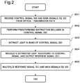
- Fig. 2 is a flowchart illustrating an optical transmission method being an example of an operation procedure of the optical transmission device 100.
- the reception unit 110 receives the control signal S0 and the main signals S2 and S3 from the optical transmission path (step S01 in Fig. 2 ).
- the control unit 120 performs a predetermined instruction included in the control signal S0 (step S02).
- the extraction unit 130 extracts light in a wavelength band of the control signal S0 (step S03).
- the response signal generation unit 140 modulates the extracted light according to the control signal S0, and outputs the response signal S1 (step S04).
- the multiplexing unit 150 multiplexes the response signal S1 and the main signals S2 and S3 (step S05).
- the response signal generation unit 140 performs modulation according to the control signal S0 only on a signal in a band being extracted by the extraction unit 130, and a response signal is not superimposed on the main signals S2 and S3.
- the optical transmission device 100 can generate the response signal capable of suppressing a decrease in reception sensitivity during reception of the response signal S1.
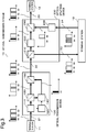
- Fig. 3 is a block diagram illustrating a configuration example of an optical transmission system 10 according to a second example embodiment of the present invention.
- the optical transmission system 10 includes terminal stations 11 to 13, an optical transmission device 100, and an optical splitting device 200.
- An optical fiber cable is used as optical transmission paths 21 to 25.
- the terminal station 11 transmits a WDM signal including a control signal S0 and main signals S2 and S3 to the optical transmission device 100 by using the optical transmission path 21.
- the control signal S0 is a signal for controlling the optical transmission device 100
- the main signal S2 is a signal addressed to the terminal station 12 from the terminal station 11
- the main signal S3 is a signal addressed to the terminal station 13 from the terminal station 11.
- the optical transmission system 10 includes the optical transmission device 100 described in the first example embodiment.
- the optical transmission device 100 outputs a WDM signal including a response signal S1 and the main signals S2 and S3 to the optical splitting device 200 by using the optical transmission path 22.
- a detailed configuration example of the optical transmission device 100 in the second example embodiment will be described later with reference to Fig. 4 .
- the optical splitting device 200 splits the WDM signal received from the optical transmission path 22 into directions to the terminal station 12 and the terminal station 13.
- the optical splitting device 200 is, for example, an optical add/drop multiplexer (OADM) device, and includes functions of splitting and combining a WDM signal.
- the optical splitting device 200 includes optical couplers 210 and 240 and optical filters 220 and 230.
- the optical splitting device 200 outputs a WDM signal including the main signal S3 to the terminal station 13, and outputs a WDM signal including the response signal S1, the main signal S2, and a main signal S4 to the terminal station 12.
- OADM optical add/drop multiplexer
- the terminal station 13 selects the main signal S3 being a signal addressed to the terminal station 13 from the WDM signal received from the optical transmission path 23, and demodulates the main signal S3. Furthermore, the terminal station 13 sends a WDM signal that is addressed to the terminal station 12 and includes the main signal S4 and a dummy signal D1 to the optical splitting device 200 by using the optical transmission path 24.
- the main signal S4 is a signal in the same wavelength band as that of the main signal S3.
- the dummy signal D1 is an optical signal in a wavelength range different from that of the main signal S4, which is added for maintaining, in a predetermined range, input power of the WDM signal to an optical amplifier on the optical transmission path 24, and the dummy signal D1 does not include information that needs to be transmitted. Sending of the dummy signal D1 is not necessary.
- the terminal station 12 demodulates the response signal S1 included in the WDM signal received from the optical transmission path 25, and confirms response data included in the response signal S1.
- the response data include information about a control result of the optical transmission device 100 by the control signal S0. Therefore, the terminal station 12 can confirm the control result of the optical transmission device 100 by the control signal S0.
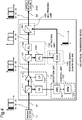
- Fig. 4 is a block diagram illustrating a configuration example of the optical transmission device 100 according to the second example embodiment.
- the optical transmission device 100 includes a reception unit 110, a control unit 120, an extraction unit 130, a response signal generation unit 140, and a multiplexing unit 150, similarly to the first example embodiment.
- the optical transmission device 100 is an optical repeater that relays a received WDM signal. In the present example embodiment, a more detailed configuration of the optical transmission device 100 will be described.
- the reception unit 110 includes an optical coupler 111, an optical receiver (RX) 112, an optical amplifier 113, and a drive circuit (LD) 114.
- the optical coupler 111 splits the WDM signal received from the optical transmission path 21, and outputs the WDM signals to the optical receiver 112 and the optical amplifier 113.
- the optical receiver 112 performs O/E conversion on the control signal S0 included in one of the split WDM signals, and outputs the control signal S0 to the control unit 120.
- the optical receiver 112 may include an optical filter that passes a wavelength including the control signal S0. Control data (for example, an instruction of a control content) are included in the control signal S0.
- the optical amplifier 113 is an optical fiber amplifier, and amplifies the WDM signal including the control signal S0 and the main signals S2 and S3 and outputs the WDM signal to the extraction unit 130.
- An excitation LD of the optical amplifier 113 and a control circuit of the excitation LD are included in the drive circuit 114.
- the control circuit of the excitation LD controls output power of the excitation LD in such a way that output power of the optical amplifier 113 falls within a constant range, for example.
- the control unit 120 includes a central processing unit (CPU) 121 and a memory (MEM) 122.
- a function of the optical transmission device 100 may be achieved by executing a program stored in the memory 122 by the central processing unit 121 (computer).
- the memory 122 is a tangible and non-transitory recording medium, and is, for example, a semiconductor memory or a fixed magnetic disk device, which is not limited thereto.
- the control unit 120 extracts control data from an electric signal acquired by performing the O/E conversion on the control signal S0, controls the optical transmission device 100, based on the control data, and generates response data.
- the response data include an execution result (control result) of control of the optical transmission device 100, based on the control signal S0.
- the response data include, for example, information about a success or a failure of control and state information of each unit of the optical transmission device 100 being read based on control.
- the response data are output as an electric signal from the control unit 120 to the response signal generation unit 140.
- the response data are expressed by ON/OFF of an electric signal.
- the response data express a control result by combining one or more pieces of data of 8 bits.
- the extraction unit 130 includes a coupler 131 and optical filters (FIL) 132 and 133.
- the coupler 131 splits, into two, the WDM signal that is output from the optical amplifier 113 and includes the control signal S0 and the main signals S2 and S3, and outputs the WDM signals to the optical filters 132 and 133.
- the optical filter 132 blocks light in a wavelength range of the control signal S0, and passes light in a wavelength range of the main signals S2 and S3.
- the optical filter 133 passes the light in the wavelength range of the control signal S0, and blocks the light in the wavelength range of the main signals S2 and S3.
- the main signals S2 and S3 are output to the multiplexing unit 150, and the control signal S0 is output to the response signal generation unit 140.
- a wavelength filter that separates a wavelength range including the control signal S0 and a wavelength range including the main signals S2 and S3 may be used.
- a variable optical attenuator (VOA) 141 is used as the response signal generation unit 140.
- the variable optical attenuator 141 modulates an amplitude of light with a wavelength of the control signal S0, based on ON/OFF (namely, "0" and "1" of a bit string) of the response data received from the control unit 120.
- the variable optical attenuator 141 controls an amount of attenuation in such a way as to be maximum or minimum according to ON/OFF of the response data. By such control, the response data are transmitted according to ON/OFF of the light with the wavelength of the control signal S0.
- the response signal S1 is an optical signal acquired by on-off keying modulation of the response data, the response data being a control result by the control signal S0.
- a modulation speed (namely, a width of a bit string) of the response data and a length of a bit string can be defined in a range in which the response signal S1 does not affect transmission of the main signals S2 to S4.
- Fig. 5 is a diagram for describing an operation example of the optical transmission device 100 according to the second example embodiment.
- a vertical direction indicates the control signal S0, the response signal S1, and an operation of each unit, and a horizontal axis indicates time.
- the control signal S0 received from the terminal station 11 is continuous wave (CW) light when there is no control from the terminal station 11.
- CW continuous wave
- the control signal S0 is modulated by the control data.
- the control signal S0 is a burst signal.
- the sending of the control data by the control signal S0 continues until a time T1.
- the control signal S0 returns to CW light.
- the control unit 120 performs control of the optical transmission device 100, based on the control data demodulated by the optical receiver 112, and also collects a control result from a control target.
- the control unit 120 waits for reception of the control data to be terminated at the time T1, and outputs a control result as response data to the response signal generation unit 140 at and after a time T2.
- the control unit 120 may hold the response data in the memory 122 until the time T2. Further, the control unit 120 may acquire information about whether the control signal S0 includes the control data from the reception unit 110.
- the variable optical attenuator 141 When receiving the response data from the control unit 120, the variable optical attenuator 141 modulates, by the response data, the control signal S0 that has become the CW light, and generates the response signal S1.
- the response signal S1 is output to the multiplexing unit 150.
- the response signal S1 may be modulated in such a way as to be associated with an amplitude of the response data. For example, an amount of attenuation of the variable optical attenuator 141 may be set to minimum while a bit of the response data is "1", and an amount of attenuation of the variable optical attenuator 141 may be set to maximum while a bit of the response data is "0".
- an amount of attenuation of the variable optical attenuator 141 may be set to maximum while a bit of the response data is "1", and an amount of attenuation of the variable optical attenuator 141 may be set to minimum while a bit of the response data is "0".
- Such a procedure of the modulation generates the response signal S1 acquired by modulating presence or absence of light according to ON/OFF of the response data.
- the modulation operation of the variable optical attenuator 141 is also terminated, and the response signal S1 returns to the CW light.
- the control unit 120 stops sending of the response data to the response signal generation unit 140. In this way, a collision between the response signal S1 and the control signal S0 in the response signal generation unit 140 can be avoided. Further, the modulation by the response data is not performed during the reception of the control data S0.
- control data S0 may be output as the response signal S1 to the multiplexing unit 150 with an amount of attenuation of the variable optical attenuator 141 being set to minimum.
- control data S0 may not be output to the multiplexing unit 150 with an amount of attenuation of the variable optical attenuator 141 being set to maximum.
- Fig. 6 is a flowchart illustrating an example of an operation procedure of the optical transmission device 100 according to the second example embodiment.
- the optical transmission device 100 receives the WDM signal including the control signal S0 from the optical transmission path 21, and outputs one of the WDM signals split by the optical coupler 111 to the optical receiver 112 (step S11 in Fig. 6 ).
- the optical receiver 112 performs the O/E conversion on the control signal S0, and outputs the control signal S0 to the control unit 120 (step S12).
- the control unit 120 controls the optical transmission device 100, based on an instruction (control data) included in the control signal S0, and generates response data (step S13).
- the control unit 120 After confirming the reception termination of the control signal S0, the control unit 120 outputs the response data to the response signal generation unit 140 (step S14).
- the response signal generation unit 140 controls the variable optical attenuator 141 according to the response data, modulates light with a wavelength of the control signal S0 being extracted by the extraction unit 130, and generates the response signal S1 (step S15).
- the multiplexing unit 150 multiplexes the response signal S1 and the main signals S2 and S3, and outputs the response signal S1 and the main signals S2 and S3 to the optical transmission path 22 (step S16).
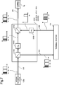
- Fig. 7 is a block diagram illustrating a configuration example of the optical splitting device 200 according to the second example embodiment.
- the optical coupler 210 splits the WDM signal output from the optical transmission device 100 to the optical transmission path 22, and outputs the WDM signals to the terminal station 13 and the optical filter 220.
- the optical filter 220 passes the wavelength range of the response signal S1 and the main signal S2, and blocks the wavelength range of the main signal S3.
- the optical filter 230 passes the wavelength range of the main signal S4, and blocks the wavelength range of the dummy signal D1.
- the optical coupler 240 generates the WDM signal by combining the response signal S1 and the main signal S2 that are transmitted from the optical transmission device 100 with the main signal S4 transmitted from the terminal station 13, and outputs the WDM signal to the optical transmission path 25.
- a wavelength filter that combines the response signal S1 and the main signal S2 with the main signal S4 may be used. With such a configuration, the optical splitting device 200 outputs, without any change, the response signal S1 received from the optical transmission device 100 to the terminal station 12.
- the response signal S1 is controlled by ON/OFF, and thus has a high modulation degree.
- the control data of the response signal S1 are extracted from the optical power of the WDM signal at the terminal station 12, the extraction of the response signal S1 is facilitated as compared to when a drive current of the excitation LD is modulated and the control data are superimposed on the WDM signal with a low modulation degree.
- the response signal generation unit 140 performs modulation of ON/OFF according to the control signal S0 only on a signal in a band being extracted by the extraction unit 130, and generates the response signal S1.
- a modulation degree of the response signal S1 can be increased, and thus a decrease in reception sensitivity to the response signal at the terminal station can be suppressed.
- the optical transmission system 10 may include only the terminal station 11 (first terminal station), the terminal station 12 (second terminal station), and the optical transmission device 100, and the optical transmission path 22 connected to an output of the optical transmission device 100 may be directly connected to the terminal station 12.
- an effect capable of suppressing a decrease in reception sensitivity to the response signal at the terminal station can also be acquired.
- variable optical attenuator 141 is used in the response signal generation unit 140.
- another optical device capable of controlling an amount of attenuation with an electric signal may be used instead of the variable optical attenuator 141.
- the response signal S1 may be generated by modulating CW light by using an optical modulator using an optical waveguide.
- an optical switch and an optical shutter capable of controlling passage and blockage of light with an electric signal may be used instead of the variable optical attenuator.
- the procedure according to the second example embodiment and a general procedure of superimposing a response signal on an amplitude of a WDM signal by control of a drive current of the drive circuit 114 may be used together.
- the control of the excitation power may be performed by the control unit 120.
- an amount of transmission of response data can be increased by transmitting different pieces of response data by different procedures.
- redundancy may be provided by transmitting the same response data by different procedures.
- a response signal is generated not by modulating the entire wavelength of a WDM signal but by modulating a specific wavelength band (band of the response signal S1).
- a response signal by modulation having a high extinction ratio can be generated.
- a response signal generated by using the specific wavelength band can reach a terminal station that receives the response signal without being affected by Add/Drop by an adjacent optical splitting device.
- the optical transmission system 10 according to the second example embodiment can provide the optical transmission device capable of generating a response signal having high reception sensitivity.
- An optical transmission device including:
- control means controls modulation by the response signal generation means, based on an execution result of the predetermined instruction.
- optical transmission device according to Supplementary Note 1 or 2, wherein the response signal generation means modulates the extracted light in the band of the control signal by on-off-keying.
- control means causes the response signal generation means to generate the response signal when the control signal including the predetermined instruction is not received in the reception means.
- optical transmission device wherein light in a band of the control signal is continuous light when the control signal does not include the predetermined instruction, and the response signal generation means generates the response signal by modulating the continuous light.
- optical transmission device according to any one of Supplementary Notes 1 to 5, further including an optical amplifier that amplifies the main signal by an excitation light source, wherein the control means controls excitation power of the excitation light source according to the control signal.
- the optical transmission device according to any one of Supplementary Notes 1 to 6, wherein the response signal generation means modulates the extracted light in the band of the control signal by using any one of a variable optical attenuator, an optical modulator, an optical switch, and an optical shutter.
- An optical transmission system wherein a first terminal station that sends an optical signal including a control signal including the predetermined instruction and the main signal, the optical transmission device according to any one of Supplementary Notes 1 to 7 that receives the optical signal including the control signal including the predetermined instruction and the main signal from the first terminal station, and a second terminal station that receives the response signal are connected to one another with an optical transmission path.
- An optical transmission method including:
- optical transmission method according to any one of Supplementary Notes 9 to 11, wherein the response signal is generated when the control signal including the predetermined instruction is not received.
- optical transmission method wherein light in a band of the control signal is continuous light when the control signal does not include the predetermined instruction, and the optical transmission method further includes generating the response signal by modulating the continuous light.
- optical transmission method according to any one of Supplementary Notes 9 to 13, further including controlling excitation power of an excitation light source of an optical amplifier that amplifies the main signal according to the control signal.
- a program of an optical transmission device causing a computer of the optical transmission device to perform:
- optical transmission system and the optical transmission device according to each of the example embodiments are applicable to both of a land optical transmission system and a submarine optical transmission system.
- each of the example embodiments is not necessarily exclusive.
- the action and effects of the present invention may be achieved by a configuration combining the whole or a part of the above-mentioned example embodiments.
Landscapes
- Engineering & Computer Science (AREA)
- Computer Networks & Wireless Communication (AREA)
- Signal Processing (AREA)
- Physics & Mathematics (AREA)
- Electromagnetism (AREA)
- Optical Communication System (AREA)
Abstract
Description
- The present invention relates to an optical transmission device and an optical transmission method, and particularly relates to an optical transmission device and an optical transmission method that output a response signal according to a received control signal.
- In a submarine optical transmission system, control of a repeater installed on a sea bottom is performed from a terminal station on land.
Fig. 8 is a block diagram illustrating a configuration of a general submarineoptical transmission system 900. The submarineoptical transmission system 900 includesterminal stations submarine repeater 940, and asubmarine splitting device 950. - The
submarine repeater 940 receives an optical signal acquired by wavelength-multiplexing a control signal S0 and main signals S2 and S3 from theterminal station 910. The control signal S0 and the main signals S2 and S3 have wavelength bands different from one another. InFig. 8 , spectra of the control signal S0 and the main signals S2 to S4 of each unit on a transmission path are also illustrated in a diagram with a vertical axis as amplitude and a horizontal axis as wavelength. The control signal S0 is a signal for controlling thesubmarine repeater 940. The main signal S2 is a signal sent from theterminal station 910 to theterminal station 920. The main signal S3 is a signal sent from theterminal station 910 to theterminal station 930. Hereinafter, a wavelength-multiplexed signal is described as a wavelength division multiplexed (WDM) signal. - The
submarine repeater 940 includes anoptical coupler 941, anoptical receiver 942, acontrol unit 943, adrive unit 944, a laser diode (LD) 945, and anoptical amplifier 946. Theoptical coupler 941 splits the control signal S0 and the main signals S2 and S3, and outputs the control signal S0 and the main signals S2 and S3 to theoptical receiver 942 and theoptical amplifier 946. Theoptical receiver 942 performs optical-electrical (O/E) conversion on the control signal S0. Thecontrol unit 943 processes the control signal, and generates a response signal, based on a processing result. Theoptical amplifier 946 amplifies the control signal S0 and the main signals S2 and S3 split by theoptical coupler 941. The LD 945 generates excitation light of theoptical amplifier 946. - The
drive unit 944 modulates an amplitude of a drive current of theLD 945, based on the response signal generated by thecontrol unit 943. In this way, a WDM signal including the control signal S0 and the main signals S2 and S3 input to theoptical amplifier 946 is subjected to the amplitude modulation. A black region in the diagram indicating the spectrum of each of the signals inFig. 8 schematically indicates the amplitude modulation of the WDM signal. - The
submarine splitting device 950 includesoptical couplers optical coupler 951 splits the WDM signal output from theoptical amplifier 946 of thesubmarine repeater 940, and outputs the WDM signals to theterminal station 930 and theoptical filter 952. Theterminal station 930 selects the main signal S3 being a signal addressed to theterminal station 930 from the received control signal S0 and the received main signals S2 and S3, and demodulates the main signal S3. Theterminal station 930 sends a main signal S4 addressed to theterminal station 920. The main signal S4 is a signal having the same wavelength band as that of the main signal S3. - The
optical filter 952 blocks a wavelength range of the main signal S3. Theoptical coupler 953 outputs, to theterminal station 920, the WDM signal acquired by combining the control signal S0 and the main signal S2 that are transmitted from theterminal station 910 with the main signal S4 transmitted from theterminal station 930. As a result, theterminal station 920 can receive the main signals S2 and S4, and can also extract the response signal generated by thecontrol unit 943 from an amplitude change in the control signal S0 and the main signal S2. - In relation to the present invention,
PTL 1 describes a configuration in which a Raman amplification relay device generates a response signal with respect to a control signal, and sends the response signal to another terminal station. PTLs 2 and 3 describe a technique for monitoring an optical repeater by using monitoring signal light. -
- [PTL 1] Japanese Unexamined Patent Application Publication No.
2004-228761 - [PTL 2] Japanese Unexamined Patent Application Publication No.
2005-136602 - [PTL 3] Japanese Unexamined Patent Application Publication No.
2001-223643 - The
drive unit 944 controls excitation light power of theoptical amplifier 946 by causing a fluctuation in drive current of theLD 945 by a response signal. As a result, the response signal is superimposed on light output power of theoptical amplifier 946. At this time, an amplitude of the optical signal (S0, S2, and S3) included in the whole band that passes through theoptical amplifier 946 is modulated based on the response signal. Therefore, when a modulation degree of the response signal is increased by increasing an amount of fluctuation in drive current of theLD 945, a transmission characteristic deteriorates due to an increase in amplitude fluctuation of the main signal, and thus the modulation degree of the response signal cannot be increased much. On the other hand, when the WDM signal output from thesubmarine repeater 940 passes through thesubmarine splitting device 950 and is transmitted to theterminal station 920, the main signal S3 is blocked by theoptical filter 952, and the main signal S4 that does not include a component of the response signal is multiplexed by theoptical coupler 953. Thus, when the signal multiplexed by theoptical coupler 953 is received by theterminal station 920, the modulation degree of the response signal decreases during demodulation of the response signal based on the WDM signal received by theterminal station 920. - In other words, a general submarine optical transmission system has a problem that it is difficult to increase a modulation degree of a response signal generated by a submarine repeater, and, as a result, it is difficult to improve reception sensitivity of the response signal at a terminal station.
- An object of the present invention is to provide an optical transmission device and an optical transmission method, being capable of generating a response signal that can suppress a decrease in reception sensitivity during reception of the response signal.
- An optical transmission device according to the present invention includes:
- a reception means for receiving a control signal including a predetermined instruction and a main signal, via an optical transmission path connected to a terminal station;
- a control means for performing the predetermined instruction of the received control signal;
- an extraction means for extracting light in a band of the control signal;
- a response signal generation means for modulating the extracted light in the band of the control signal, and outputting a response signal; and
- a multiplexing means for multiplexing and outputting the response signal and the main signal, wherein
- the control means controls modulation by the response signal generation means according to the control signal.
- An optical transmission method according to the present invention includes:
- receiving a control signal including a predetermined instruction and a main signal, via an optical transmission path connected to a terminal station;
- performing the predetermined instruction of the received control signal;
- extracting light in a band of the control signal;
- modulating the extracted light in the band of the control signal according to the control signal, and outputting a response signal; and multiplexing and outputting the response signal and the main signal.
- The optical transmission device and the optical transmission method according to the present invention can generate a response signal capable of suppressing a decrease in reception sensitivity during reception of the response signal.
-
- [
Fig. 1] Fig. 1 is a block diagram illustrating a configuration example of anoptical transmission device 100 according to a first example embodiment. - [
Fig. 2] Fig. 2 is a flowchart illustrating an example of an operation procedure of theoptical transmission device 100 according to the first example embodiment. - [
Fig. 3] Fig. 3 is a block diagram illustrating a configuration example of anoptical transmission system 10 according to a second example embodiment. - [
Fig. 4] Fig. 4 is a block diagram illustrating a configuration example of anoptical transmission device 100 according to the second example embodiment. - [
Fig. 5] Fig. 5 is a diagram for describing an operation example of theoptical transmission device 100 according to the second example embodiment. - [
Fig. 6] Fig. 6 is a flowchart illustrating an example of an operation procedure of theoptical transmission device 100 according to the second example embodiment. - [
Fig. 7] Fig. 7 is a block diagram illustrating a configuration example of anoptical splitting device 200 according to the second example embodiment. - [
Fig. 8] Fig. 8 is a block diagram illustrating a configuration of a general submarineoptical transmission system 900. - Example embodiments according to the present invention will be described below. An arrow in a block diagram for describing the example embodiments exemplifies an orientation of a signal for description, and does not limit the orientation of the signal. Further, a component that has already been described is provided with the same reference sign, and the repeated description thereof is omitted.
-
Fig. 1 is a block diagram illustrating a configuration example of anoptical transmission device 100 according to a first example embodiment of the present invention. Theoptical transmission device 100 receives a WDM signal including a control signal S0, a main signal S2, and a main signal S3 from an optical transmission path, and outputs a WDM signal including a response signal S1 and the main signals S2 and S3 to the optical transmission path. Theoptical transmission device 100 includes areception unit 110, acontrol unit 120, anextraction unit 130, a responsesignal generation unit 140, and amultiplexing unit 150. Note that a wavelength band of the control signal S0 may be a dedicated wavelength band different from that of a main signal system, or may be a wavelength band that is not used among wavelength bands of the main signal system. - The
reception unit 110 serves as a reception means for receiving the control signal S0 including a predetermined instruction and the main signals S2 and S3 via the optical transmission path connected to a terminal station. Thecontrol unit 120 serves as a control means for performing the predetermined instruction included in the received control signal S0. Theextraction unit 130 serves as an extraction means for extracting light in a wavelength band of the control signal S0, and outputting the light to the responsesignal generation unit 140. The response signal generation unit serves as a response signal generation means for modulating the extracted light in the band of the control signal S0, and outputting the light as the response signal S1. Themultiplexing unit 150 serves as a multiplexing means for multiplexing and outputting the response signal S1 and the main signals S2 and S3. Herein, thecontrol unit 120 controls modulation by the responsesignal generation unit 140 according to the control signal S0. - Note that, in block diagrams in the present example embodiment and the subsequent example embodiment, spectra of the control signal S0, the response signal S1, and the main signal of each unit are also illustrated in a diagram with a vertical axis as amplitude and a horizontal axis as wavelength. A black region of the spectra of the control signal S0 and the response signal S1 schematically indicates amplitude modulation.
-
Fig. 2 is a flowchart illustrating an optical transmission method being an example of an operation procedure of theoptical transmission device 100. Thereception unit 110 receives the control signal S0 and the main signals S2 and S3 from the optical transmission path (step S01 inFig. 2 ). Thecontrol unit 120 performs a predetermined instruction included in the control signal S0 (step S02). Theextraction unit 130 extracts light in a wavelength band of the control signal S0 (step S03). The responsesignal generation unit 140 modulates the extracted light according to the control signal S0, and outputs the response signal S1 (step S04). Themultiplexing unit 150 multiplexes the response signal S1 and the main signals S2 and S3 (step S05). - In the
optical transmission device 100 having such a configuration, the responsesignal generation unit 140 performs modulation according to the control signal S0 only on a signal in a band being extracted by theextraction unit 130, and a response signal is not superimposed on the main signals S2 and S3. As a result, theoptical transmission device 100 can generate the response signal capable of suppressing a decrease in reception sensitivity during reception of the response signal S1. -
Fig. 3 is a block diagram illustrating a configuration example of anoptical transmission system 10 according to a second example embodiment of the present invention. Theoptical transmission system 10 includesterminal stations 11 to 13, anoptical transmission device 100, and anoptical splitting device 200. An optical fiber cable is used asoptical transmission paths 21 to 25. Theterminal station 11 transmits a WDM signal including a control signal S0 and main signals S2 and S3 to theoptical transmission device 100 by using theoptical transmission path 21. The control signal S0 is a signal for controlling theoptical transmission device 100, the main signal S2 is a signal addressed to theterminal station 12 from theterminal station 11, and the main signal S3 is a signal addressed to theterminal station 13 from theterminal station 11. Theoptical transmission system 10 includes theoptical transmission device 100 described in the first example embodiment. Theoptical transmission device 100 outputs a WDM signal including a response signal S1 and the main signals S2 and S3 to theoptical splitting device 200 by using theoptical transmission path 22. A detailed configuration example of theoptical transmission device 100 in the second example embodiment will be described later with reference toFig. 4 . - The
optical splitting device 200 splits the WDM signal received from theoptical transmission path 22 into directions to theterminal station 12 and theterminal station 13. Theoptical splitting device 200 is, for example, an optical add/drop multiplexer (OADM) device, and includes functions of splitting and combining a WDM signal. Theoptical splitting device 200 includesoptical couplers optical filters optical splitting device 200 outputs a WDM signal including the main signal S3 to theterminal station 13, and outputs a WDM signal including the response signal S1, the main signal S2, and a main signal S4 to theterminal station 12. A detailed configuration example of theoptical splitting device 200 will be described later with reference toFig. 7 . - The
terminal station 13 selects the main signal S3 being a signal addressed to theterminal station 13 from the WDM signal received from theoptical transmission path 23, and demodulates the main signal S3. Furthermore, theterminal station 13 sends a WDM signal that is addressed to theterminal station 12 and includes the main signal S4 and a dummy signal D1 to theoptical splitting device 200 by using theoptical transmission path 24. The main signal S4 is a signal in the same wavelength band as that of the main signal S3. The dummy signal D1 is an optical signal in a wavelength range different from that of the main signal S4, which is added for maintaining, in a predetermined range, input power of the WDM signal to an optical amplifier on theoptical transmission path 24, and the dummy signal D1 does not include information that needs to be transmitted. Sending of the dummy signal D1 is not necessary. - The
terminal station 12 demodulates the response signal S1 included in the WDM signal received from theoptical transmission path 25, and confirms response data included in the response signal S1. The response data include information about a control result of theoptical transmission device 100 by the control signal S0. Therefore, theterminal station 12 can confirm the control result of theoptical transmission device 100 by the control signal S0. -
Fig. 4 is a block diagram illustrating a configuration example of theoptical transmission device 100 according to the second example embodiment. Theoptical transmission device 100 includes areception unit 110, acontrol unit 120, anextraction unit 130, a responsesignal generation unit 140, and amultiplexing unit 150, similarly to the first example embodiment. Theoptical transmission device 100 is an optical repeater that relays a received WDM signal. In the present example embodiment, a more detailed configuration of theoptical transmission device 100 will be described. - The
reception unit 110 includes anoptical coupler 111, an optical receiver (RX) 112, anoptical amplifier 113, and a drive circuit (LD) 114. Theoptical coupler 111 splits the WDM signal received from theoptical transmission path 21, and outputs the WDM signals to theoptical receiver 112 and theoptical amplifier 113. Theoptical receiver 112 performs O/E conversion on the control signal S0 included in one of the split WDM signals, and outputs the control signal S0 to thecontrol unit 120. Theoptical receiver 112 may include an optical filter that passes a wavelength including the control signal S0. Control data (for example, an instruction of a control content) are included in the control signal S0. Theoptical amplifier 113 is an optical fiber amplifier, and amplifies the WDM signal including the control signal S0 and the main signals S2 and S3 and outputs the WDM signal to theextraction unit 130. An excitation LD of theoptical amplifier 113 and a control circuit of the excitation LD are included in thedrive circuit 114. The control circuit of the excitation LD controls output power of the excitation LD in such a way that output power of theoptical amplifier 113 falls within a constant range, for example. - The
control unit 120 includes a central processing unit (CPU) 121 and a memory (MEM) 122. A function of theoptical transmission device 100 may be achieved by executing a program stored in thememory 122 by the central processing unit 121 (computer). Thememory 122 is a tangible and non-transitory recording medium, and is, for example, a semiconductor memory or a fixed magnetic disk device, which is not limited thereto. - The
control unit 120 extracts control data from an electric signal acquired by performing the O/E conversion on the control signal S0, controls theoptical transmission device 100, based on the control data, and generates response data. The response data include an execution result (control result) of control of theoptical transmission device 100, based on the control signal S0. The response data include, for example, information about a success or a failure of control and state information of each unit of theoptical transmission device 100 being read based on control. The response data are output as an electric signal from thecontrol unit 120 to the responsesignal generation unit 140. In the present example embodiment, the response data are expressed by ON/OFF of an electric signal. For example, the response data express a control result by combining one or more pieces of data of 8 bits. - The
extraction unit 130 includes acoupler 131 and optical filters (FIL) 132 and 133. Thecoupler 131 splits, into two, the WDM signal that is output from theoptical amplifier 113 and includes the control signal S0 and the main signals S2 and S3, and outputs the WDM signals to theoptical filters optical filter 132 blocks light in a wavelength range of the control signal S0, and passes light in a wavelength range of the main signals S2 and S3. Theoptical filter 133 passes the light in the wavelength range of the control signal S0, and blocks the light in the wavelength range of the main signals S2 and S3. With such a configuration, the main signals S2 and S3 are output to themultiplexing unit 150, and the control signal S0 is output to the responsesignal generation unit 140. As theextraction unit 130, a wavelength filter that separates a wavelength range including the control signal S0 and a wavelength range including the main signals S2 and S3 may be used. - In the present example embodiment, a variable optical attenuator (VOA) 141 is used as the response
signal generation unit 140. The variable optical attenuator 141 modulates an amplitude of light with a wavelength of the control signal S0, based on ON/OFF (namely, "0" and "1" of a bit string) of the response data received from thecontrol unit 120. The variable optical attenuator 141 controls an amount of attenuation in such a way as to be maximum or minimum according to ON/OFF of the response data. By such control, the response data are transmitted according to ON/OFF of the light with the wavelength of the control signal S0. Hereinafter, the light with the wavelength of the control signal S0 modulated by the variable optical attenuator 141 is referred to as a response signal S1. In other words, the response signal S1 is an optical signal acquired by on-off keying modulation of the response data, the response data being a control result by the control signal S0. A modulation speed (namely, a width of a bit string) of the response data and a length of a bit string can be defined in a range in which the response signal S1 does not affect transmission of the main signals S2 to S4. -
Fig. 5 is a diagram for describing an operation example of theoptical transmission device 100 according to the second example embodiment. A vertical direction indicates the control signal S0, the response signal S1, and an operation of each unit, and a horizontal axis indicates time. The control signal S0 received from theterminal station 11 is continuous wave (CW) light when there is no control from theterminal station 11. When sending of a signal including control data starts at a time T0, the control signal S0 is modulated by the control data. In this way, the control signal S0 is a burst signal. The sending of the control data by the control signal S0 continues until a time T1. When the sending of the control data is terminated at the time T1, the control signal S0 returns to CW light. - The
control unit 120 performs control of theoptical transmission device 100, based on the control data demodulated by theoptical receiver 112, and also collects a control result from a control target. Thecontrol unit 120 waits for reception of the control data to be terminated at the time T1, and outputs a control result as response data to the responsesignal generation unit 140 at and after a time T2. Thecontrol unit 120 may hold the response data in thememory 122 until the time T2. Further, thecontrol unit 120 may acquire information about whether the control signal S0 includes the control data from thereception unit 110. - When receiving the response data from the
control unit 120, the variable optical attenuator 141 modulates, by the response data, the control signal S0 that has become the CW light, and generates the response signal S1. The response signal S1 is output to themultiplexing unit 150. The response signal S1 may be modulated in such a way as to be associated with an amplitude of the response data. For example, an amount of attenuation of the variable optical attenuator 141 may be set to minimum while a bit of the response data is "1", and an amount of attenuation of the variable optical attenuator 141 may be set to maximum while a bit of the response data is "0". Conversely, an amount of attenuation of the variable optical attenuator 141 may be set to maximum while a bit of the response data is "1", and an amount of attenuation of the variable optical attenuator 141 may be set to minimum while a bit of the response data is "0". Such a procedure of the modulation generates the response signal S1 acquired by modulating presence or absence of light according to ON/OFF of the response data. - When generation of the response data is terminated at a time T3, the modulation operation of the variable optical attenuator 141 is also terminated, and the response signal S1 returns to the CW light. Note that, when sending of the control signal S0 from the terminal station S11 starts during the generation of the response signal S1, the
control unit 120 stops sending of the response data to the responsesignal generation unit 140. In this way, a collision between the response signal S1 and the control signal S0 in the responsesignal generation unit 140 can be avoided. Further, the modulation by the response data is not performed during the reception of the control data S0. During the reception of the control signal S0, the control data S0 may be output as the response signal S1 to themultiplexing unit 150 with an amount of attenuation of the variable optical attenuator 141 being set to minimum. Alternatively, the control data S0 may not be output to themultiplexing unit 150 with an amount of attenuation of the variable optical attenuator 141 being set to maximum. -
Fig. 6 is a flowchart illustrating an example of an operation procedure of theoptical transmission device 100 according to the second example embodiment. Theoptical transmission device 100 receives the WDM signal including the control signal S0 from theoptical transmission path 21, and outputs one of the WDM signals split by theoptical coupler 111 to the optical receiver 112 (step S11 inFig. 6 ). Theoptical receiver 112 performs the O/E conversion on the control signal S0, and outputs the control signal S0 to the control unit 120 (step S12). Thecontrol unit 120 controls theoptical transmission device 100, based on an instruction (control data) included in the control signal S0, and generates response data (step S13). After confirming the reception termination of the control signal S0, thecontrol unit 120 outputs the response data to the response signal generation unit 140 (step S14). The responsesignal generation unit 140 controls the variable optical attenuator 141 according to the response data, modulates light with a wavelength of the control signal S0 being extracted by theextraction unit 130, and generates the response signal S1 (step S15). Themultiplexing unit 150 multiplexes the response signal S1 and the main signals S2 and S3, and outputs the response signal S1 and the main signals S2 and S3 to the optical transmission path 22 (step S16). -
Fig. 7 is a block diagram illustrating a configuration example of theoptical splitting device 200 according to the second example embodiment. Theoptical coupler 210 splits the WDM signal output from theoptical transmission device 100 to theoptical transmission path 22, and outputs the WDM signals to theterminal station 13 and theoptical filter 220. Theoptical filter 220 passes the wavelength range of the response signal S1 and the main signal S2, and blocks the wavelength range of the main signal S3. Theoptical filter 230 passes the wavelength range of the main signal S4, and blocks the wavelength range of the dummy signal D1. Theoptical coupler 240 generates the WDM signal by combining the response signal S1 and the main signal S2 that are transmitted from theoptical transmission device 100 with the main signal S4 transmitted from theterminal station 13, and outputs the WDM signal to theoptical transmission path 25. As theoptical coupler 240, a wavelength filter that combines the response signal S1 and the main signal S2 with the main signal S4 may be used. With such a configuration, theoptical splitting device 200 outputs, without any change, the response signal S1 received from theoptical transmission device 100 to theterminal station 12. - The response signal S1 is controlled by ON/OFF, and thus has a high modulation degree. Thus, even when the control data of the response signal S1 are extracted from the optical power of the WDM signal at the
terminal station 12, the extraction of the response signal S1 is facilitated as compared to when a drive current of the excitation LD is modulated and the control data are superimposed on the WDM signal with a low modulation degree. - In other words, in the
optical transmission system 10 and theoptical transmission device 100 according to the second example embodiment, the responsesignal generation unit 140 performs modulation of ON/OFF according to the control signal S0 only on a signal in a band being extracted by theextraction unit 130, and generates the response signal S1. As a result, a modulation degree of the response signal S1 can be increased, and thus a decrease in reception sensitivity to the response signal at the terminal station can be suppressed. - Note that the
optical transmission system 10 according to the second example embodiment may include only the terminal station 11 (first terminal station), the terminal station 12 (second terminal station), and theoptical transmission device 100, and theoptical transmission path 22 connected to an output of theoptical transmission device 100 may be directly connected to theterminal station 12. In such a configuration, an effect capable of suppressing a decrease in reception sensitivity to the response signal at the terminal station can also be acquired. - In the second example embodiment, the variable optical attenuator 141 is used in the response
signal generation unit 140. However, another optical device capable of controlling an amount of attenuation with an electric signal may be used instead of the variable optical attenuator 141. For example, the response signal S1 may be generated by modulating CW light by using an optical modulator using an optical waveguide. Further, since the response signal S1 is an ON/OFF signal of light, an optical switch and an optical shutter capable of controlling passage and blockage of light with an electric signal may be used instead of the variable optical attenuator. - Further, the procedure according to the second example embodiment and a general procedure of superimposing a response signal on an amplitude of a WDM signal by control of a drive current of the drive circuit 114 (namely, control of excitation power of an excitation light source) may be used together. The control of the excitation power may be performed by the
control unit 120. In this way, an amount of transmission of response data can be increased by transmitting different pieces of response data by different procedures. Alternatively, redundancy may be provided by transmitting the same response data by different procedures. - In the
optical transmission system 10 according to the second example embodiment, a response signal is generated not by modulating the entire wavelength of a WDM signal but by modulating a specific wavelength band (band of the response signal S1). Thus, a response signal by modulation having a high extinction ratio can be generated. Further, a response signal generated by using the specific wavelength band can reach a terminal station that receives the response signal without being affected by Add/Drop by an adjacent optical splitting device. As described above, theoptical transmission system 10 according to the second example embodiment can provide the optical transmission device capable of generating a response signal having high reception sensitivity. - The whole or part of the example embodiments disclosed above can be described as, but not limited to, the following supplementary notes.
- An optical transmission device, including:
- reception means for receiving a control signal including a predetermined instruction and a main signal, via an optical transmission path connected to a terminal station;
- control means for performing the predetermined instruction of the received control signal;
- extraction means for extracting light in a band of the control signal;
- response signal generation means for modulating the extracted light in the band of the control signal, and outputting a response signal; and
- multiplexing means for multiplexing and outputting the response signal and the main signal, wherein
- the control means controls modulation by the response signal generation means according to the control signal.
- The optical transmission device according to
Supplementary Note 1, wherein
the control means controls modulation by the response signal generation means, based on an execution result of the predetermined instruction. - The optical transmission device according to
Supplementary Note 1 or 2, wherein
the response signal generation means modulates the extracted light in the band of the control signal by on-off-keying. - The optical transmission device according to any one of
Supplementary Notes 1 to 3, wherein
the control means causes the response signal generation means to generate the response signal when the control signal including the predetermined instruction is not received in the reception means. - The optical transmission device according to
Supplementary Note 4, wherein
light in a band of the control signal is continuous light when the control signal does not include the predetermined instruction, and the response signal generation means generates the response signal by modulating the continuous light. - The optical transmission device according to any one of
Supplementary Notes 1 to 5, further including
an optical amplifier that amplifies the main signal by an excitation light source, wherein
the control means controls excitation power of the excitation light source according to the control signal. - The optical transmission device according to any one of
Supplementary Notes 1 to 6, wherein
the response signal generation means modulates the extracted light in the band of the control signal by using any one of a variable optical attenuator, an optical modulator, an optical switch, and an optical shutter. - An optical transmission system, wherein
a first terminal station that sends an optical signal including a control signal including the predetermined instruction and the main signal, the optical transmission device according to any one ofSupplementary Notes 1 to 7 that receives the optical signal including the control signal including the predetermined instruction and the main signal from the first terminal station, and
a second terminal station that receives the response signal are connected to one another with an optical transmission path. - An optical transmission method, including:
- receiving a control signal including a predetermined instruction and a main signal, via an optical transmission path connected to a terminal station, and performing the predetermined instruction of the received control signal;
- extracting light in a band of the control signal;
- modulating the extracted light in the band of the control signal according to the control signal, and outputting a response signal; and
- multiplexing and outputting the response signal and the main signal.
- The optical transmission method according to Supplementary Note 9, wherein
the modulating the extracted band of the control signal is performed based on an execution result of the predetermined instruction. - The optical transmission method according to
Supplementary Note 9 or 10, wherein
the modulating the extracted light in the band of the control signal is performed by on-off-keying. - The optical transmission method according to any one of Supplementary Notes 9 to 11, wherein
the response signal is generated when the control signal including the predetermined instruction is not received. - The optical transmission method according to
Supplementary Note 12, wherein
light in a band of the control signal is continuous light when the control signal does not include the predetermined instruction, and the optical transmission method further includes generating the response signal by modulating the continuous light. - The optical transmission method according to any one of Supplementary Notes 9 to 13, further including
controlling excitation power of an excitation light source of an optical amplifier that amplifies the main signal according to the control signal. - A program of an optical transmission device causing a computer of the optical transmission device to perform:
- a procedure of receiving a control signal including a predetermined instruction and a main signal, via an optical transmission path connected to a terminal station;
- a procedure of performing the predetermined instruction of the received control signal;
- a procedure of extracting light in a band of the control signal;
- a procedure of modulating the extracted light in the band of the control signal according to the control signal, and outputting a response signal; and
- a procedure of multiplexing and outputting the response signal and the main signal.
- While the invention has been particularly shown and described with reference to example embodiments thereof, the invention is not limited to these embodiments. It will be understood by those of ordinary skill in the art that various changes in form and details may be made therein without departing from the spirit and scope of the present invention as defined by the claims. For example, the optical transmission system and the optical transmission device according to each of the example embodiments are applicable to both of a land optical transmission system and a submarine optical transmission system.
- Further, the configuration described in each of the example embodiments is not necessarily exclusive. The action and effects of the present invention may be achieved by a configuration combining the whole or a part of the above-mentioned example embodiments.
- This application is based upon and claims the benefit of priority from Japanese patent application No.
2017-207102, filed on October 26, 2017 -
- 10
- Optical transmission system
- 11 to 13
- Terminal station
- 21 to 25
- Optical transmission path
- 100
- Optical transmission device
- 110
- Reception unit
- 111
- Optical coupler
- 112
- Optical receiver
- 113
- Optical amplifier
- 114
- Drive circuit
- 120
- Control unit
- 121
- Central processing unit
- 122
- Memory
- 130
- Extraction unit
- 131
- Coupler
- 132
- Optical filter
- 133
- Optical filter
- 140
- Response signal generation unit
- 141
- Variable optical attenuator
- 150
- Multiplexing unit
- 200
- Optical splitting device
- 210, 240
- Optical coupler
- 220, 230
- Optical filter
- 900
- Submarine optical transmission system
- 910, 920, 930
- Terminal station
- 940
- Submarine repeater
- 941, 951, 953
- Optical coupler
- 942
- Optical receiver
- 943
- Control unit
- 944
- Drive unit
- 946
- Optical amplifier
- 950
- Submarine splitting device
- 952
- Optical filter
Claims (15)
- An optical transmission device, comprising:reception means for receiving a control signal including a predetermined instruction and a main signal, via an optical transmission path connected to a terminal station;control means for performing the predetermined instruction of the received control signal;extraction means for extracting light in a band of the control signal;response signal generation means for modulating the extracted light in the band of the control signal, and outputting a response signal; andmultiplexing means for multiplexing and outputting the response signal and the main signal, whereinthe control means controls modulation by the response signal generation means according to the control signal.
- The optical transmission device according to claim 1, wherein
the control means controls modulation by the response signal generation means, based on an execution result of the predetermined instruction. - The optical transmission device according to claim 1 or 2, wherein
the response signal generation means modulates the extracted light in the band of the control signal by on-off-keying. - The optical transmission device according to any one of claims 1 to 3, wherein
the control means causes the response signal generation means to generate the response signal when the control signal including the predetermined instruction is not received in the reception means. - The optical transmission device according to claim 4, wherein
light in a band of the control signal is continuous light when the control signal does not include the predetermined instruction, and the response signal generation means generates the response signal by modulating the continuous light. - The optical transmission device according to any one of claims 1 to 5, further comprising
an optical amplifier that amplifies the main signal by using an excitation light source, wherein
the control means controls excitation power of the excitation light source according to the control signal. - The optical transmission device according to any one of claims 1 to 6, wherein
the response signal generation means modulates the extracted light in the band of the control signal by using any one of a variable optical attenuator, an optical modulator, an optical switch, and an optical shutter. - An optical transmission system, whereina first terminal station that sends an optical signal including a control signal including the predetermined instruction and the main signal, the optical transmission device according to any one of claims 1 to 7 that receives the optical signal including the control signal including the predetermined instruction and the main signal from the first terminal station, anda second terminal station that receives the response signal are connected to one another with an optical transmission path.
- An optical transmission method, comprising:receiving a control signal including a predetermined instruction and a main signal, via an optical transmission path connected to a terminal station, and performing the predetermined instruction of the received control signal;extracting light in a band of the control signal;modulating the extracted light in the band of the control signal according to the control signal, and outputting a response signal; andmultiplexing and outputting the response signal and the main signal.
- The optical transmission method according to claim 9, wherein
the modulating the extracted band of the control signal is performed based on an execution result of the predetermined instruction. - The optical transmission method according to claim 9 or 10, wherein
the modulating the extracted light in the band of the control signal is performed by on-off-keying. - The optical transmission method according to any one of claims 9 to 11, wherein
the response signal is generated when the control signal including the predetermined instruction is not received. - The optical transmission method according to claim 12, wherein
light in a band of the control signal is continuous light when the control signal does not include the predetermined instruction, and the optical transmission method further comprises generating the response signal by modulating the continuous light. - The optical transmission method according to any one of claims 9 to 13, further comprising
controlling excitation power of an excitation light source of an optical amplifier that amplifies the main signal, according to the control signal. - A recording medium that records a program of an optical transmission device causing a computer of the optical transmission device to perform:a procedure of receiving a control signal including a predetermined instruction and a main signal, via an optical transmission path connected to a terminal station;a procedure of performing the predetermined instruction of the received control signal;a procedure of extracting light in a band of the control signal;a procedure of modulating the extracted light in the band of the control signal according to the control signal, and outputting a response signal; anda procedure of multiplexing and outputting the response signal and the main signal.
Applications Claiming Priority (2)
| Application Number | Priority Date | Filing Date | Title |
|---|---|---|---|
| JP2017207102 | 2017-10-26 | ||
| PCT/JP2018/039255 WO2019082862A1 (en) | 2017-10-26 | 2018-10-23 | Optical transmission device and optical transmission method |
Publications (2)
| Publication Number | Publication Date |
|---|---|
| EP3703278A1 true EP3703278A1 (en) | 2020-09-02 |
| EP3703278A4 EP3703278A4 (en) | 2020-12-16 |
Family
ID=66246486
Family Applications (1)
| Application Number | Title | Priority Date | Filing Date |
|---|---|---|---|
| EP18870817.6A Withdrawn EP3703278A4 (en) | 2017-10-26 | 2018-10-23 | Optical transmission device and optical transmission method |
Country Status (5)
| Country | Link |
|---|---|
| US (1) | US11057110B2 (en) |
| EP (1) | EP3703278A4 (en) |
| JP (1) | JPWO2019082862A1 (en) |
| CN (1) | CN111279632B (en) |
| WO (1) | WO2019082862A1 (en) |
Families Citing this family (1)
| Publication number | Priority date | Publication date | Assignee | Title |
|---|---|---|---|---|
| EP4007186A1 (en) * | 2019-07-29 | 2022-06-01 | NEC Corporation | Re-modulation device, demodulation reception device, modulation transmission device, modulation communication system, re-modulation method, and recording medium |
Family Cites Families (18)
| Publication number | Priority date | Publication date | Assignee | Title |
|---|---|---|---|---|
| US5864414A (en) | 1994-01-26 | 1999-01-26 | British Telecommunications Public Limited Company | WDM network with control wavelength |
| GB9401488D0 (en) | 1994-01-26 | 1994-03-23 | British Telecomm | Optical communications |
| JPH09321701A (en) | 1996-05-31 | 1997-12-12 | Fujitsu Ltd | Optical communication system and optical amplifier |
| JP2000278248A (en) * | 1999-03-24 | 2000-10-06 | Fujitsu Ltd | Sub-signal communication system of optical communication system, optical linear repeater and optical terminal equipment |
| JP3440872B2 (en) * | 1999-05-07 | 2003-08-25 | 日本電気株式会社 | Supervisory signal transfer device in optical transmission system |
| JP2001244885A (en) * | 2000-02-28 | 2001-09-07 | Nippon Telegr & Teleph Corp <Ntt> | Optical circuits and WDM optical networks |
| JP3509748B2 (en) | 2000-12-18 | 2004-03-22 | 日本電気株式会社 | Optical amplification repeater and monitoring method thereof |
| JP4632585B2 (en) | 2001-07-16 | 2011-02-16 | 富士通株式会社 | Optical transmission system |
| JP4467213B2 (en) | 2001-08-14 | 2010-05-26 | 富士通株式会社 | Optical transmission system |
| JP2003348017A (en) * | 2002-05-29 | 2003-12-05 | Nec Corp | Variable gain equalizer and method for monitoring remote control gain equalization |
| JP4122884B2 (en) * | 2002-07-30 | 2008-07-23 | 日本電気株式会社 | Optical repeater |
| JP4205959B2 (en) | 2003-01-21 | 2009-01-07 | 富士通株式会社 | Relay device and Raman amplification relay system |
| JP2005136602A (en) | 2003-10-29 | 2005-05-26 | Nec Corp | Optical repeater and optical repeating system |
| JP4710357B2 (en) * | 2005-03-09 | 2011-06-29 | 日本電気株式会社 | Optical amplification apparatus, operation control method thereof, and program |
| JP5099137B2 (en) * | 2007-07-27 | 2012-12-12 | 富士通株式会社 | Optical amplifier and optical transmission system including the same |
| ES2641472T3 (en) * | 2013-01-15 | 2017-11-10 | Huawei Marine Networks Co., Limited | Communications device and method |
| WO2015145985A1 (en) * | 2014-03-27 | 2015-10-01 | 日本電気株式会社 | Optical relay device, optical communication system, optical relay method, and storage medium |
| JP6765711B2 (en) | 2016-05-16 | 2020-10-07 | 有限会社イノン | Underwater camera arm member |
-
2018
- 2018-10-23 US US16/755,959 patent/US11057110B2/en active Active
- 2018-10-23 WO PCT/JP2018/039255 patent/WO2019082862A1/en not_active Ceased
- 2018-10-23 CN CN201880069500.7A patent/CN111279632B/en active Active
- 2018-10-23 JP JP2019551136A patent/JPWO2019082862A1/en active Pending
- 2018-10-23 EP EP18870817.6A patent/EP3703278A4/en not_active Withdrawn
Also Published As
| Publication number | Publication date |
|---|---|
| US11057110B2 (en) | 2021-07-06 |
| CN111279632B (en) | 2023-05-09 |
| JPWO2019082862A1 (en) | 2020-10-22 |
| CN111279632A (en) | 2020-06-12 |
| WO2019082862A1 (en) | 2019-05-02 |
| EP3703278A4 (en) | 2020-12-16 |
| US20200266912A1 (en) | 2020-08-20 |
Similar Documents
| Publication | Publication Date | Title |
|---|---|---|
| JP6317357B2 (en) | Disaster recovery in branched optical networks | |
| JP5387311B2 (en) | Wavelength multiplexed optical network system and wavelength multiplexed optical transmission / reception method | |
| US11336386B2 (en) | Submarine branching apparatus, optical submarine cable system, and optical communication method | |
| EP3439201A1 (en) | Signal loopback circuit and signal loopback method | |
| US6823138B2 (en) | Optical communications terminal station, optical signal transmission method, and optical signal increasing method in wavelength multiplexing system | |
| JP6497439B2 (en) | COMMUNICATION DEVICE, COMMUNICATION METHOD, AND COMMUNICATION SYSTEM | |
| JPWO2013183146A1 (en) | Optical fiber connection state determination method, optical fiber connection state determination optical module, and optical transmission device | |
| US10819443B2 (en) | Optical communications system and optical frequency control method | |
| EP3934135B1 (en) | Optical branch coupler and optical branching coupling method | |
| US11025360B2 (en) | Optical add and drop multiplexer, optical communication system, and method for controlling optical add and drop multiplexer | |
| US11057110B2 (en) | Optical transmission device and optical transmission method | |
| US11817907B2 (en) | Optical transmission device and optical transmission method | |
| US12451962B2 (en) | Monitoring signal light output apparatus, submarine apparatus, and optical communication system | |
| US12574111B2 (en) | Light control device, method for controlling light control device, and recording medium | |
| EP3952150A1 (en) | Optical add/drop multiplexer and optical transmission method | |
| EP3859998A1 (en) | Optical transmitter and optical receiver | |
| JP7428234B2 (en) | Spectrum monitoring equipment, submarine equipment and optical communication systems | |
| CN113491078A (en) | Optical multiplexer/demultiplexer, optical submarine cable system, optical multiplexing/demultiplexing method, and non-transitory computer-readable medium | |
| JP2015039110A (en) | Transmission device | |
| WO2024201555A1 (en) | Optical receiver, optical monitor system, and optical reception method |
Legal Events
| Date | Code | Title | Description |
|---|---|---|---|
| STAA | Information on the status of an ep patent application or granted ep patent |
Free format text: STATUS: THE INTERNATIONAL PUBLICATION HAS BEEN MADE |
|
| PUAI | Public reference made under article 153(3) epc to a published international application that has entered the european phase |
Free format text: ORIGINAL CODE: 0009012 |
|
| STAA | Information on the status of an ep patent application or granted ep patent |
Free format text: STATUS: REQUEST FOR EXAMINATION WAS MADE |
|
| 17P | Request for examination filed |
Effective date: 20200426 |
|
| AK | Designated contracting states |
Kind code of ref document: A1 Designated state(s): AL AT BE BG CH CY CZ DE DK EE ES FI FR GB GR HR HU IE IS IT LI LT LU LV MC MK MT NL NO PL PT RO RS SE SI SK SM TR |
|
| AX | Request for extension of the european patent |
Extension state: BA ME |
|
| A4 | Supplementary search report drawn up and despatched |
Effective date: 20201118 |
|
| RIC1 | Information provided on ipc code assigned before grant |
Ipc: H04B 10/29 20130101ALI20201112BHEP Ipc: H04B 10/077 20130101AFI20201112BHEP |
|
| DAV | Request for validation of the european patent (deleted) | ||
| DAX | Request for extension of the european patent (deleted) | ||
| STAA | Information on the status of an ep patent application or granted ep patent |
Free format text: STATUS: THE APPLICATION HAS BEEN WITHDRAWN |
|
| 18W | Application withdrawn |
Effective date: 20220811 |