EP3703243A1 - Device for detecting rotation direction and method for detecting rotation direction of motor, and motor control device - Google Patents
Device for detecting rotation direction and method for detecting rotation direction of motor, and motor control device Download PDFInfo
- Publication number
- EP3703243A1 EP3703243A1 EP18871102.2A EP18871102A EP3703243A1 EP 3703243 A1 EP3703243 A1 EP 3703243A1 EP 18871102 A EP18871102 A EP 18871102A EP 3703243 A1 EP3703243 A1 EP 3703243A1
- Authority
- EP
- European Patent Office
- Prior art keywords
- motor
- rotation direction
- current
- voltage
- detector
- Prior art date
- Legal status (The legal status is an assumption and is not a legal conclusion. Google has not performed a legal analysis and makes no representation as to the accuracy of the status listed.)
- Granted
Links
Images


Classifications
-
- H—ELECTRICITY
- H02—GENERATION; CONVERSION OR DISTRIBUTION OF ELECTRIC POWER
- H02P—CONTROL OR REGULATION OF ELECTRIC MOTORS, ELECTRIC GENERATORS OR DYNAMO-ELECTRIC CONVERTERS; CONTROLLING TRANSFORMERS, REACTORS OR CHOKE COILS
- H02P7/00—Arrangements for regulating or controlling the speed or torque of electric DC motors
- H02P7/0094—Arrangements for regulating or controlling the speed or torque of electric DC motors wherein the position is detected using the ripple of the current caused by the commutator
-
- H—ELECTRICITY
- H02—GENERATION; CONVERSION OR DISTRIBUTION OF ELECTRIC POWER
- H02P—CONTROL OR REGULATION OF ELECTRIC MOTORS, ELECTRIC GENERATORS OR DYNAMO-ELECTRIC CONVERTERS; CONTROLLING TRANSFORMERS, REACTORS OR CHOKE COILS
- H02P7/00—Arrangements for regulating or controlling the speed or torque of electric DC motors
- H02P7/03—Arrangements for regulating or controlling the speed or torque of electric DC motors for controlling the direction of rotation of DC motors
Definitions
- the invention relates to a technique for detecting a motor operation, and more particularly relates to a device and a method for detecting a rotation direction of a motor without using a rotation sensing element.
- Patent Document 1 discloses a DC motor that detects the rotation speed of the motor using a current ripple which is generated when the contact between the brush and the commutator piece is switched.
- a rotation direction detecting device for a motor according to the invention is connected to a power supply line that supplies electric power to the motor and detects a rotation direction of the motor.
- the rotation direction detecting device includes: a current detector detecting a direction of a current flowing through the motor; a voltage detector detecting voltages before and after the motor in the power supply line; and a rotation direction detector detecting the rotation direction of the motor based on the direction of the current detected by the current detector and the voltages detected by the voltage detector.
- the direction of the current flowing through the motor is detected by the current detector, and the voltages before and after the motor are detected by the voltage detector. Then, based on the direction of the current and the voltages before and after the motor, the rotation direction of the motor is detected by the rotation direction detector.
- the rotation direction of the motor can be detected without using a rotation sensing element. Therefore, the rotation direction can be detected without using a rotation sensing element even if the motor enters the coasting state after energization, the motor rotates reversely after the motor stops, or the armature rotates due to an external force when the motor is not energized, for example.
- the voltage detector may include a voltage monitor that compares the voltages before and after the motor with a predetermined threshold value and converts the voltages into Hi/Lo signals respectively to be output.
- the power supply line may be connected to a terminal on one side and a terminal on the other side of the motor.
- the current detector may determine the direction of the current between a case where the current flows from the terminal on one side to the terminal on the other side and a case where the current flows from the terminal on the other side to the terminal on one side.
- the voltage detector may respectively detect voltages of the terminal side on one side and the terminal side on the other side of the motor in the power supply line.
- the rotation direction detector may detect the rotation direction of the motor by a combination of the directions of the current of the two cases and the Hi/Lo signals converted and formed with respect to the voltages on the one side and the other side of the motor.
- the rotation direction detector may determine that the motor is rotating in one direction when the direction of the current is from the one side to the other side, and the voltage on the one side in the power supply line is Hi and the voltage on the other side is Lo, and determine that the motor is rotating in the other direction when the direction of the current is from the other side to the one side, and the voltage on the one side in the power supply line is Lo and the voltage on the other side is Hi.
- the rotation direction detector may determine that the motor is rotating in one direction when the direction of the current is from the other side to the one side, and the voltage on the one side and the voltage on the other side in the power supply line are both recognized as Lo, and determine that the motor is rotating in the other direction when the direction of the current is from the one side to the other side, and the voltage on the one side and the voltage on the other side in the power supply line are both recognized as Lo.
- a rotation direction detecting method for a motor is for detecting a rotation direction of the motor.
- the motor is connected to a power supply line for supplying electric power to the motor.
- the rotation direction detecting method includes: detecting a direction of a current flowing through the motor; detecting voltages before and after the motor in the power supply line; and detecting the rotation direction of the motor based on the direction of the current and the voltages.
- the direction of the current flowing through the motor is detected, the voltages before and after the motor are detected, and the rotation direction of the motor is detected based on the direction of the current and the voltages before and after the motor.
- the rotation direction of the motor can be detected without using a rotation sensing element. Therefore, the rotation direction can be detected without using a rotation sensing element even if the motor enters the coasting state after energization, the motor rotates reversely after the motor stops, or the armature rotates due to an external force when the motor is not energized, for example.
- the voltages before and after the motor may be compared with a predetermined threshold value and the voltages may be converted into Hi/Lo signals respectively; and the rotation direction of the motor may be detected based on the direction of the current and the Hi/Lo signals corresponding to the voltages.
- the power supply line may be connected to a terminal on one side and a terminal on the other side of the motor.
- the direction of the current may be determined between a case where the current flows from the terminal on one side to the terminal on the other side and a case where the current flows from the terminal on the other side to the terminal on one side.
- Voltages of the terminal side on one side and the terminal side on the other side of the motor may be respectively detected as the voltages before and after the motor in the power supply line.
- the rotation direction of the motor may be detected by a combination of the directions of the current of the two cases and the Hi/Lo signals converted and formed with respect to the voltages on the one side and the other side of the motor.
- a motor control device includes a rotation direction detecting device connected to a power supply line that supplies electric power to a motor and detecting a rotation direction of the motor.
- the rotation direction detecting device includes: a current detector detecting a direction of a current flowing through the motor; a voltage detector detecting voltages before and after the motor in the power supply line; and a rotation direction detector detecting the rotation direction of the motor based on the direction of the current detected by the current detector and the voltages detected by the voltage detector.
- the rotation direction detecting device which includes the current detector detecting the direction of the current flowing through the motor; the voltage detector detecting the voltages before and after the motor; and the rotation direction detector detecting the rotation direction of the motor based on the direction of the current and the voltages before and after the motor, is provided in the motor control device to detect the rotation direction of the motor based on the direction of the current and the voltages before and after the motor.
- the rotation direction of the motor can be detected without using a rotation sensing element.
- the rotation direction can be detected without using a rotation sensing element even if the motor enters the coasting state after energization, the motor rotates reversely after the motor stops, or the armature rotates due to an external force when the motor is not energized, for example.
- the motor operation state can be accurately grasped, and the accuracy of the rotation position information can be increased to improve the motor control accuracy.
- the current detector detecting the direction of the current flowing through the motor
- the voltage detector detecting the voltages before and after the motor
- the rotation direction detector detecting the rotation direction of the motor based on the direction of the current and the voltages before and after the motor.
- the direction of the current flowing through the motor is detected, the voltages before and after the motor are detected, and the rotation direction of the motor is detected based on the direction of the current and the voltages before and after the motor.
- the rotation direction of the motor can be detected without using a rotation sensing element. Therefore, the rotation direction can be detected without using a rotation sensing element even if the motor enters the coasting state after energization, the motor rotates reversely after the motor stops, or the armature rotates due to an external force when the motor is not energized, for example.
- the rotation direction detecting device which includes the current detector detecting the direction of the current flowing through the motor; the voltage detector detecting the voltages before and after the motor; and the rotation direction detector detecting the rotation direction of the motor based on the direction of the current and the voltages before and after the motor, is provided in the motor control device.
- the rotation direction of the motor can be detected without using a rotation sensing element. Therefore, the rotation direction can be detected without using a rotation sensing element even if the motor enters the coasting state after energization, the motor rotates reversely after the motor stops, or the armature rotates due to an external force when the motor is not energized, for example.
- the motor operation state can be accurately grasped to improve the motor control accuracy.
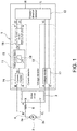
- FIG. 1 is a block diagram showing a configuration of a rotation direction detecting device 1 which is the first embodiment of the invention, and a rotation direction detecting method according to the invention is also performed by the device.
- the rotation direction detecting device 1 is, for example, used in a motor operation control device for a power window of a vehicle, and detects whether the motor is rotating and the rotation direction by a logical combination of the direction of a motor current (armature current) and a motor terminal voltage without using a rotation sensing element.
- the rotation direction detecting device 1 is connected to a power supply line 4 that supplies electric power from a motor driver 2 to a brush DC motor 3 (hereinafter, abbreviated as motor 3).
- the power supply line 4 is connected to a terminal 3a (terminal on one side) and a terminal 3b (terminal on the other side) of the motor 3.
- the power supply line 4 is provided with a shunt resistor 5.
- the rotation direction detecting device 1 is connected to points A and B before and after the shunt resistor 5 (the side of the motor driver 2 and the side of the motor 3) and points A and C before and after the motor 3.
- the rotation direction detecting device 1 In the rotation direction detecting device 1, the current (motor current) flowing through the power supply line 4 is detected from before and after the shunt resistor 5, and the terminal voltage of the motor 3 is detected from before and after the motor 3.
- the output of the rotation direction detecting device 1 is sent to a drive control device of the motor 3.
- the drive control device controls the operation of the motor 3 based on the detection result of the rotation direction detecting device 1.
- the rotation direction detecting device 1 includes a current detector 11 connected before and after the shunt resistor 5, a voltage detector 12 connected before and after the motor 3, and a rotation direction detector 13 detecting the rotation direction of the motor 3 based on information obtained by the current detector 11 and the voltage detector 12.
- the current detector 11 is provided with a current monitor 14, a voltage signal adjuster 15, and a current waveform direction determination part 16.
- the current detector 11 detects the direction (A ⁇ B, B ⁇ A) of the current flowing through the shunt resistor 5 and sends the current direction to the rotation direction detector 13 as current direction information CI.
- the voltage detector 12 is provided with a voltage monitor 17.
- the voltage detector 12 detects the voltages at the points A and C before and after the motor 3 due to the induced voltage, and sends the detected voltages to the rotation direction detector 13 as motor terminal voltage information VI.
- the rotation direction detector 13 determines the rotation direction of the motor 3 based on the current direction information CI obtained from the current waveform direction determination part 16 and the motor terminal voltage information VI obtained from the voltage monitor 17.
- FIG. 2 is an explanatory diagram showing an internal configuration of the current waveform direction determination part 16 and the rotation direction detector 13.
- a logic circuit is formed in the rotation direction detector 13, and the rotation direction of the motor 3 is detected from a combination of the current direction information CI indicating the current direction and the motor terminal voltage information VI indicating the voltages at two ends of the motor.
- a detection signal is output from a port R when the motor 3 rotates forward and from a port L when the motor 3 rotates reversely.
- clockwise rotation is referred to as forward rotation (rotation in one direction) and counterclockwise rotation is referred to as reverse rotation (rotation in the other direction), but the forward and reverse rotations are relative, and any of the clockwise and counterclockwise rotation directions may be the forward (or reverse) direction.
- the current monitor 14 of the current detector 11 detects the voltage difference (voltage drop) before and after the shunt resistor 5 to detect the voltage of the current flowing through the power supply line 4, and outputs the change of the voltage as a voltage change signal (electric signal) S1.
- FIG. 3 is an example of the output signal from the current monitor 14.
- the voltage difference before and after the shunt resistor 5 is output in a differentially amplified form with reference to a bias voltage Voff1 based on the power supply voltage.
- the voltage change signal S1 is output as a vertically symmetric waveform with respect to Voff1 depending on the current direction.
- the voltage change signal S1 output from the current monitor 14 contains a noise component and a current ripple component as can be seen from FIG. 3 . Therefore, in the rotation direction detecting device 1, the central value of the current ripple component is extracted from the voltage change signal S1 by the voltage signal adjuster 15 as a change component of the motor current.
- FIG. 4 is an explanatory diagram showing processing in the voltage signal adjuster 15.
- the voltage signal adjuster 15 uses a low-pass filter 18 to extract from the voltage change signal S1 ( FIG. 3 ) the change component of the motor current ( FIG. 4 ), and outputs it as a current waveform signal CV.
- the current waveform direction determination part 16 determines the direction of the motor current based on the current waveform signal CV input from the voltage signal adjuster 15. As described above, the voltage change signal S1 has a vertically symmetric waveform depending on the current direction, and similar to the voltage change signal S1, the current waveform signal CV also has a vertically symmetric waveform depending on the current direction. Thus, in the current waveform direction determination part 16, the current waveform signal CV is compared with a midpoint voltage Voff1', and the current direction is determined as A ⁇ B when the waveform changes above the midpoint voltage Voff1', and the current direction is determined as B ⁇ A when the waveform changes below the midpoint voltage Voff1'. The current waveform direction determination part 16 sends the current direction information CI from the port P to the rotation direction detector 13 when the current direction is A ⁇ B, and sends the current direction information CI from the port Q to the rotation direction detector 13 when the current direction is B ⁇ A.
- the voltages at the points A and C before and after the motor 3 are detected by the voltage monitor 17.
- the voltage across the points A and C is compared with a predetermined threshold value Vs (for example, 1V). Then, if the voltage across the points A and C is larger than the threshold value Vs, a Hi signal is formed, and if the voltage is smaller than the threshold value Vs, a Lo signal is formed and amplified, and the signal is output from the voltage monitor 17 as the motor terminal voltage information VI. That is, in the voltage monitor 17, the voltage across the points A and C is converted into the Hi/Lo signal and input to the rotation direction detector 13. In the rotation direction detector 13, the rotation direction of the motor 3 is detected by a combination of the motor terminal voltage information VI (Hi or Lo) and the current direction information CI (A ⁇ B or B ⁇ A).
- FIG. 5 is a table showing the detection processing in the rotation direction detector 13.
- the "motor drive output” in FIG. 5 indicates the output of the motor driver 2.
- the current direction is A ⁇ B and the motor 3 rotates forward (shown as clockwise in the table).
- the output X side is - and the output Y side is +
- the current direction is B ⁇ A and the motor 3 rotates reversely (shown as counterclockwise in the table).
- ⁇ motor drive output
- the current waveform direction determination part 16 sends the current direction information CI (A ⁇ B) from the port P to the rotation direction detector 13.
- the information CI (A ⁇ B) is input to AND1 of the rotation direction detector 13.
- the current waveform direction determination part 16 sends the current direction information CI (B ⁇ A) from the port Q to the rotation direction detector 13.
- the information CI (B ⁇ A) is input to AND 2 of the rotation direction detector 13.
- the Lo signal is output from the voltage monitor 17 for both A and C.
- the motor terminal voltage information VI is both in the Lo state. Therefore, the rotation direction detector 13 recognizes that the motor terminal voltages A and C are both Lo.
- the Lo signal is output from the voltage monitor 17 for both A and C, and the rotation direction detector 13 recognizes that the motor terminal voltages A and C are both Lo.
- the rotation direction detecting device 1 of the invention it is possible to detect whether the motor 3 rotates and the rotation direction by a logical combination of the direction of the motor current and the motor terminal voltage without using a rotation sensing element. For example, whether the motor rotates and the direction can be accurately detected even if the motor enters the coasting state after energization, the motor rotates reversely after the motor stops, or the armature rotates due to an external force when the motor is not energized. Therefore, the motor operation state can be accurately grasped, and the accuracy of the rotation position information can be increased to improve the motor control accuracy. As a result, for example, the pinch detection accuracy of the motor for power window can be increased to improve the reliability.
- the elimination of a rotation sensing element eliminates the need for an element housing space, and correspondingly the size of the motor is reduced and the manufacturing cost of the motor is also reduced.
- FIG. 8 is an explanatory diagram showing an internal configuration of a rotation direction detector 21 in a rotation direction detecting device 20 which is the second embodiment of the invention.
- an induced voltage complementing circuit 22 in the rotation direction detector 21 has a configuration different from that of the induced voltage complementing circuit 19 of the first embodiment. That is, as shown in FIG. 8 , the induced voltage complementing circuit 22 is configured by omitting AND5 from the induced voltage complementing circuit 19 of the first embodiment.
- the other configuration is the same as that of the rotation direction detecting device 1 of the first embodiment.
- parts the same as those of the first embodiment are denoted by the same reference numerals and the description thereof is omitted.
- a hazard may occur when the logic is switched during a motor operation, such as when energization is stopped and the motor enters the coasting state.
- a motor operation such as when energization is stopped and the motor enters the coasting state.
- the logic switches during the coasting state. In other words, when the motor is in the coasting state and the rotation speed is decreasing, the induced voltage falls below the threshold value Vs at some point and the logic is rapidly switched.
- the motor terminal voltage information VI from the voltage monitor 17 and the complementary output Z formed from the information VI through the induced voltage complementing circuit 19 are input to OR3 and OR4. Then, the outputs of OR3 and OR4 may become unstable for a moment due to the influence of the delay time of the element.
- OR1 L
- the detection signal from the port R is also interrupted for a moment. That is, if the outputs of OR3 and OR4 become unstable during coasting, the outputs from the ports R and L may also be disturbed, and the detection accuracy of the rotation direction may drop.
- the induced voltage complementing circuit 22 of the second embodiment adopts a configuration in which AND5 is omitted, the output of NOT1 is input to OR4, and the output of NOT2 is input to OR3, so as to prevent occurrence of a hazard and reduce the number of elements.
- AND5 is omitted
- the output of NOT1 is input to OR4
- the output of NOT2 is input to OR3, so as to prevent occurrence of a hazard and reduce the number of elements.
- the current waveform direction determination part 16 sends the current direction information CI (A ⁇ B) from the port P to the rotation direction detector 21.
- the information CI (A ⁇ B) is input to AND1 of the rotation direction detector 21.
- OR1 which inputs the signal from AND1 receives the signal and outputs a signal, and a detection signal of forward rotation is output from the port R.
- the motor drive control device can grasp that the motor 3 is in the rotation state of forward rotation.
- the current waveform direction determination part 16 sends the current direction information CI (B ⁇ A) from the port Q to the rotation direction detector 21.
- the information CI (B ⁇ A) is input to AND2 of the rotation direction detector 21.
- OR2 which inputs the signal from AND2 receives the signal and outputs a signal, and a detection signal of reverse rotation is output from the port L.
- the motor drive control device can grasp that the motor 3 is in the rotation state of reverse rotation.
- the Lo signal is output for both A and C.
- OR4 and OR3 which receive the Hi signal output signals to AND4 and AND3.
- the current direction information CI A ⁇ B
- AND4 receives the signals from OR4 and the port P and outputs a signal to OR2.
- OR2 receives the signal from AND4 and outputs a detection signal of reverse rotation from the port L.
- the rotation direction detecting device of the second embodiment it is also possible to detect whether the motor 3 rotates and the rotation direction by a logical combination of the direction of the motor current and the motor terminal voltage without using a rotation sensing element.
- the induced voltage complementing circuit 22 eliminates one element from the induced voltage complementing circuit 19 of the first embodiment because AND5 is omitted, so the circuit configuration can be simplified and the number of components can be reduced.
- OR3 and OR4 input the Hi signal from NOT1 and NOT2 if any of the motor terminal voltage information VI (A and C) is Lo. Therefore, signals are output from OR3 and OR4 regardless of the values of the induced voltage and the threshold value Vs. That is, even if the logic is switched during the coasting state, the outputs of OR3 and OR4 are not affected by the delay time of the element and are maintained without interruption. Therefore, it is possible to prevent occurrence of a hazard when the logic is switched.
- the invention is not limited to the above-described embodiments, and it is possible to make various changes without departing from the scope of the invention.
- the above-described embodiments illustrate a configuration using the logic circuit as shown in FIG. 2 in the rotation direction detector 13, the configuration of the rotation direction detector 13 is not limited thereto.
- the relationship between the current direction and the motor terminal voltage may be tabulated, and the rotation direction of the motor may be detected by a CPU or the like based on this table.
- the rotation direction detecting device and the rotation direction detecting method according to the invention are applicable not only to the operation control of the motor for power window as in the above-described embodiments, but also to motors for other in-vehicle electric devices such as wipers and power seats.
- motors for other in-vehicle electric devices such as wipers and power seats.
- the invention is applicable not only to in-vehicle motors but also to brush motors used for household electric appliances or the like.
Landscapes
- Engineering & Computer Science (AREA)
- Power Engineering (AREA)
- Indicating Or Recording The Presence, Absence, Or Direction Of Movement (AREA)
- Control Of Direct Current Motors (AREA)
- Transmission And Conversion Of Sensor Element Output (AREA)
Abstract
Description
- The invention relates to a technique for detecting a motor operation, and more particularly relates to a device and a method for detecting a rotation direction of a motor without using a rotation sensing element.
- It has been widely adopted to use a sensing element such as a Hall IC to detect the rotation direction and rotation speed of an electric motor when controlling the driving of the electric motor (Patent Document 1). On the other hand, from the viewpoints of cost reduction and motor weight reduction, so-called sensing element-less motors that detect the rotation direction of the motor without using a sensing element have also been increasing in recent years. For example,
Patent Document 2 discloses a DC motor that detects the rotation speed of the motor using a current ripple which is generated when the contact between the brush and the commutator piece is switched. -
- [Patent Document 1] Japanese Laid-Open No.
2010-154688 - [Patent Document 2] Japanese Laid-Open No.
2016-77130 - However, if rotation detection is performed using a current ripple, it may be difficult to detect the rotation direction of the motor as the state changes when the motor is energized or not energized. For example, if the motor enters a coasting state after the drive current is released (OFF), the drive current value decreases, so it is difficult to detect rotation based on a current ripple. The same applies to the case where the motor rotates reversely after the motor stops or the case where the armature is rotated by an external force during non-energization. In these cases, it may not be possible to know the rotation direction of the motor.
- A rotation direction detecting device for a motor according to the invention is connected to a power supply line that supplies electric power to the motor and detects a rotation direction of the motor. The rotation direction detecting device includes: a current detector detecting a direction of a current flowing through the motor; a voltage detector detecting voltages before and after the motor in the power supply line; and a rotation direction detector detecting the rotation direction of the motor based on the direction of the current detected by the current detector and the voltages detected by the voltage detector.
- In the invention, the direction of the current flowing through the motor is detected by the current detector, and the voltages before and after the motor are detected by the voltage detector. Then, based on the direction of the current and the voltages before and after the motor, the rotation direction of the motor is detected by the rotation direction detector. Thus, the rotation direction of the motor can be detected without using a rotation sensing element. Therefore, the rotation direction can be detected without using a rotation sensing element even if the motor enters the coasting state after energization, the motor rotates reversely after the motor stops, or the armature rotates due to an external force when the motor is not energized, for example.
- In the rotation direction detecting device, the voltage detector may include a voltage monitor that compares the voltages before and after the motor with a predetermined threshold value and converts the voltages into Hi/Lo signals respectively to be output.
- Further, the power supply line may be connected to a terminal on one side and a terminal on the other side of the motor. The current detector may determine the direction of the current between a case where the current flows from the terminal on one side to the terminal on the other side and a case where the current flows from the terminal on the other side to the terminal on one side. The voltage detector may respectively detect voltages of the terminal side on one side and the terminal side on the other side of the motor in the power supply line. The rotation direction detector may detect the rotation direction of the motor by a combination of the directions of the current of the two cases and the Hi/Lo signals converted and formed with respect to the voltages on the one side and the other side of the motor.
- In addition, in the rotation direction detecting device, if electric power is supplied to the motor, the rotation direction detector may determine that the motor is rotating in one direction when the direction of the current is from the one side to the other side, and the voltage on the one side in the power supply line is Hi and the voltage on the other side is Lo, and determine that the motor is rotating in the other direction when the direction of the current is from the other side to the one side, and the voltage on the one side in the power supply line is Lo and the voltage on the other side is Hi.
- Further, in the rotation direction detecting device, if electric power is not supplied to the motor, the rotation direction detector may determine that the motor is rotating in one direction when the direction of the current is from the other side to the one side, and the voltage on the one side and the voltage on the other side in the power supply line are both recognized as Lo, and determine that the motor is rotating in the other direction when the direction of the current is from the one side to the other side, and the voltage on the one side and the voltage on the other side in the power supply line are both recognized as Lo.
- Meanwhile, a rotation direction detecting method for a motor according to the invention is for detecting a rotation direction of the motor. The motor is connected to a power supply line for supplying electric power to the motor. The rotation direction detecting method includes: detecting a direction of a current flowing through the motor; detecting voltages before and after the motor in the power supply line; and detecting the rotation direction of the motor based on the direction of the current and the voltages.
- In the invention, the direction of the current flowing through the motor is detected, the voltages before and after the motor are detected, and the rotation direction of the motor is detected based on the direction of the current and the voltages before and after the motor. Thus, the rotation direction of the motor can be detected without using a rotation sensing element. Therefore, the rotation direction can be detected without using a rotation sensing element even if the motor enters the coasting state after energization, the motor rotates reversely after the motor stops, or the armature rotates due to an external force when the motor is not energized, for example.
- In the rotation direction detecting method, the voltages before and after the motor may be compared with a predetermined threshold value and the voltages may be converted into Hi/Lo signals respectively; and the rotation direction of the motor may be detected based on the direction of the current and the Hi/Lo signals corresponding to the voltages.
- In addition, the power supply line may be connected to a terminal on one side and a terminal on the other side of the motor. The direction of the current may be determined between a case where the current flows from the terminal on one side to the terminal on the other side and a case where the current flows from the terminal on the other side to the terminal on one side. Voltages of the terminal side on one side and the terminal side on the other side of the motor may be respectively detected as the voltages before and after the motor in the power supply line. The rotation direction of the motor may be detected by a combination of the directions of the current of the two cases and the Hi/Lo signals converted and formed with respect to the voltages on the one side and the other side of the motor.
- Furthermore, a motor control device according to the invention includes a rotation direction detecting device connected to a power supply line that supplies electric power to a motor and detecting a rotation direction of the motor. The rotation direction detecting device includes: a current detector detecting a direction of a current flowing through the motor; a voltage detector detecting voltages before and after the motor in the power supply line; and a rotation direction detector detecting the rotation direction of the motor based on the direction of the current detected by the current detector and the voltages detected by the voltage detector.
- In the invention, the rotation direction detecting device, which includes the current detector detecting the direction of the current flowing through the motor; the voltage detector detecting the voltages before and after the motor; and the rotation direction detector detecting the rotation direction of the motor based on the direction of the current and the voltages before and after the motor, is provided in the motor control device to detect the rotation direction of the motor based on the direction of the current and the voltages before and after the motor. Thus, the rotation direction of the motor can be detected without using a rotation sensing element. Therefore, the rotation direction can be detected without using a rotation sensing element even if the motor enters the coasting state after energization, the motor rotates reversely after the motor stops, or the armature rotates due to an external force when the motor is not energized, for example. Hence, the motor operation state can be accurately grasped, and the accuracy of the rotation position information can be increased to improve the motor control accuracy.
- According to the motor rotation direction detecting device of the invention, the current detector detecting the direction of the current flowing through the motor, the voltage detector detecting the voltages before and after the motor, and the rotation direction detector detecting the rotation direction of the motor based on the direction of the current and the voltages before and after the motor are provided. Thus, the rotation direction of the motor can be detected without using a rotation sensing element. Therefore, the rotation direction can be detected without using a rotation sensing element even if the motor enters the coasting state after energization, the motor rotates reversely after the motor stops, or the armature rotates due to an external force when the motor is not energized, for example.
- According to the motor rotation direction detecting method of the invention, the direction of the current flowing through the motor is detected, the voltages before and after the motor are detected, and the rotation direction of the motor is detected based on the direction of the current and the voltages before and after the motor. Thus, the rotation direction of the motor can be detected without using a rotation sensing element. Therefore, the rotation direction can be detected without using a rotation sensing element even if the motor enters the coasting state after energization, the motor rotates reversely after the motor stops, or the armature rotates due to an external force when the motor is not energized, for example.
- According to the motor control device of the invention, the rotation direction detecting device, which includes the current detector detecting the direction of the current flowing through the motor; the voltage detector detecting the voltages before and after the motor; and the rotation direction detector detecting the rotation direction of the motor based on the direction of the current and the voltages before and after the motor, is provided in the motor control device. Thus, the rotation direction of the motor can be detected without using a rotation sensing element. Therefore, the rotation direction can be detected without using a rotation sensing element even if the motor enters the coasting state after energization, the motor rotates reversely after the motor stops, or the armature rotates due to an external force when the motor is not energized, for example. The motor operation state can be accurately grasped to improve the motor control accuracy.
-
-
FIG. 1 is a block diagram showing a configuration of a rotation direction detecting device which is the first embodiment of the invention. -
FIG. 2 is an explanatory diagram showing an internal configuration of the rotation direction detecting device. -
FIG. 3 is an example of an output signal from a current monitor. -
FIG. 4 is an explanatory diagram showing processing in a voltage signal adjuster. -
FIG. 5 is a table showing detection processing in a rotation direction detector. -
FIG. 6 is an explanatory diagram showing a state of a current direction and a motor terminal voltage during a motor operation (rotation mode (3)). -
FIG. 7 is an explanatory diagram showing a state of the current direction and the motor terminal voltage during a motor operation (rotation mode (4)). -
FIG. 8 is an explanatory diagram showing an internal configuration of a rotation direction detecting device in the rotation direction detecting device which is the second embodiment of the invention. -
FIG. 9 is an explanatory diagram of a hazard phenomenon in an induced voltage complementing circuit. - Hereinafter, embodiments of the invention will be described in detail with reference to the drawings. The following embodiments are to provide a rotation direction detecting device and a rotation direction detecting method that can accurately detect the rotation direction of a motor without using a rotation sensing element.
-
FIG. 1 is a block diagram showing a configuration of a rotationdirection detecting device 1 which is the first embodiment of the invention, and a rotation direction detecting method according to the invention is also performed by the device. The rotationdirection detecting device 1 is, for example, used in a motor operation control device for a power window of a vehicle, and detects whether the motor is rotating and the rotation direction by a logical combination of the direction of a motor current (armature current) and a motor terminal voltage without using a rotation sensing element. - The rotation
direction detecting device 1 is connected to apower supply line 4 that supplies electric power from amotor driver 2 to a brush DC motor 3 (hereinafter, abbreviated as motor 3). Thepower supply line 4 is connected to aterminal 3a (terminal on one side) and aterminal 3b (terminal on the other side) of themotor 3. Thepower supply line 4 is provided with ashunt resistor 5. The rotationdirection detecting device 1 is connected to points A and B before and after the shunt resistor 5 (the side of themotor driver 2 and the side of the motor 3) and points A and C before and after themotor 3. In the rotationdirection detecting device 1, the current (motor current) flowing through thepower supply line 4 is detected from before and after theshunt resistor 5, and the terminal voltage of themotor 3 is detected from before and after themotor 3. The output of the rotationdirection detecting device 1 is sent to a drive control device of themotor 3. The drive control device controls the operation of themotor 3 based on the detection result of the rotationdirection detecting device 1. - As shown in
FIG. 1 , the rotationdirection detecting device 1 includes acurrent detector 11 connected before and after theshunt resistor 5, avoltage detector 12 connected before and after themotor 3, and arotation direction detector 13 detecting the rotation direction of themotor 3 based on information obtained by thecurrent detector 11 and thevoltage detector 12. Thecurrent detector 11 is provided with acurrent monitor 14, avoltage signal adjuster 15, and a current waveformdirection determination part 16. Thecurrent detector 11 detects the direction (A→B, B→A) of the current flowing through theshunt resistor 5 and sends the current direction to therotation direction detector 13 as current direction information CI. Thevoltage detector 12 is provided with avoltage monitor 17. Thevoltage detector 12 detects the voltages at the points A and C before and after themotor 3 due to the induced voltage, and sends the detected voltages to therotation direction detector 13 as motor terminal voltage information VI. - The
rotation direction detector 13 determines the rotation direction of themotor 3 based on the current direction information CI obtained from the current waveformdirection determination part 16 and the motor terminal voltage information VI obtained from thevoltage monitor 17.FIG. 2 is an explanatory diagram showing an internal configuration of the current waveformdirection determination part 16 and therotation direction detector 13. As shown inFIG. 2 , in the rotationdirection detecting device 1, a logic circuit is formed in therotation direction detector 13, and the rotation direction of themotor 3 is detected from a combination of the current direction information CI indicating the current direction and the motor terminal voltage information VI indicating the voltages at two ends of the motor. In therotation direction detector 13, a detection signal is output from a port R when themotor 3 rotates forward and from a port L when themotor 3 rotates reversely. Here, clockwise rotation is referred to as forward rotation (rotation in one direction) and counterclockwise rotation is referred to as reverse rotation (rotation in the other direction), but the forward and reverse rotations are relative, and any of the clockwise and counterclockwise rotation directions may be the forward (or reverse) direction. - The
current monitor 14 of thecurrent detector 11 detects the voltage difference (voltage drop) before and after theshunt resistor 5 to detect the voltage of the current flowing through thepower supply line 4, and outputs the change of the voltage as a voltage change signal (electric signal) S1.FIG. 3 is an example of the output signal from thecurrent monitor 14. In thecurrent monitor 14, the voltage difference before and after theshunt resistor 5 is output in a differentially amplified form with reference to a bias voltage Voff1 based on the power supply voltage. As shown inFIG. 3 , the voltage change signal S1 is output as a vertically symmetric waveform with respect to Voff1 depending on the current direction. - The voltage change signal S1 output from the
current monitor 14 contains a noise component and a current ripple component as can be seen fromFIG. 3 . Therefore, in the rotationdirection detecting device 1, the central value of the current ripple component is extracted from the voltage change signal S1 by thevoltage signal adjuster 15 as a change component of the motor current.FIG. 4 is an explanatory diagram showing processing in thevoltage signal adjuster 15. Thevoltage signal adjuster 15 uses a low-pass filter 18 to extract from the voltage change signal S1 (FIG. 3 ) the change component of the motor current (FIG. 4 ), and outputs it as a current waveform signal CV. - The current waveform
direction determination part 16 determines the direction of the motor current based on the current waveform signal CV input from thevoltage signal adjuster 15. As described above, the voltage change signal S1 has a vertically symmetric waveform depending on the current direction, and similar to the voltage change signal S1, the current waveform signal CV also has a vertically symmetric waveform depending on the current direction. Thus, in the current waveformdirection determination part 16, the current waveform signal CV is compared with a midpoint voltage Voff1', and the current direction is determined as A→B when the waveform changes above the midpoint voltage Voff1', and the current direction is determined as B→A when the waveform changes below the midpoint voltage Voff1'. The current waveformdirection determination part 16 sends the current direction information CI from the port P to therotation direction detector 13 when the current direction is A→B, and sends the current direction information CI from the port Q to therotation direction detector 13 when the current direction is B→A. - Further, in the
voltage detector 12, the voltages at the points A and C before and after themotor 3 are detected by thevoltage monitor 17. In thevoltage monitor 17, the voltage across the points A and C is compared with a predetermined threshold value Vs (for example, 1V). Then, if the voltage across the points A and C is larger than the threshold value Vs, a Hi signal is formed, and if the voltage is smaller than the threshold value Vs, a Lo signal is formed and amplified, and the signal is output from the voltage monitor 17 as the motor terminal voltage information VI. That is, in thevoltage monitor 17, the voltage across the points A and C is converted into the Hi/Lo signal and input to therotation direction detector 13. In therotation direction detector 13, the rotation direction of themotor 3 is detected by a combination of the motor terminal voltage information VI (Hi or Lo) and the current direction information CI (A→ B or B→A). -
FIG. 5 is a table showing the detection processing in therotation direction detector 13. The "motor drive output" inFIG. 5 indicates the output of themotor driver 2. In this case, when themotor 3 is in the energized state, and the output X side is + and the output Y side is -, the current direction is A→B and themotor 3 rotates forward (shown as clockwise in the table). On the other hand, when the output X side is - and the output Y side is +, the current direction is B→A and themotor 3 rotates reversely (shown as counterclockwise in the table). In addition, when themotor 3 is in the non-energized state, there is no motor drive output ("×"). Therefore, when no electric power is supplied to themotor 3 and themotor 3 is coasting or is rotated reversely by an external force, the motor drive output becomes "×". However, in the case of reverse rotation due to the coasting state or an external force, an induced voltage is generated by the rotation of themotor 3, and a current of A→B or B→A is generated between the points A and B depending on the rotation direction. - As shown in
FIG. 5 , here, according to the motor terminal voltage information VI (Hi or Lo) and the current direction information CI (A→B or B→A), there are four combinations (rotation modes) (1) to (4). Hereinafter, the detection processing of therotation direction detector 13 in each of the rotation modes (1) to (4) will be described. - Current direction: A→B (from one side to the other side)
Motor terminal voltage: A (one side) = Hi, C (the other side) = Lo
In this case, the output X side is +, the output Y side is -, electric power is supplied to the motor 3 (energized state), and themotor 3 is rotating forward. - When the current direction is A→B, the current waveform
direction determination part 16 sends the current direction information CI (A→B) from the port P to therotation direction detector 13. The information CI (A→B) is input to AND1 of therotation direction detector 13. - On the other hand, from the
voltage monitor 17, the motor terminal voltage information VI of A = Hi and C = Lo is sent to therotation direction detector 13, and therotation direction detector 13 recognizes that A = Hi and C = Lo. A = Hi is input to AND1. AND1 generates an output only when (A→B) and (A = Hi), and in this case, a signal is sent from AND1 to OR1. Since OR1 which inputs the signal from AND1 is "OR", OR1 receives the signal and outputs a signal, and a detection signal of forward rotation is output from the port R. As a result, the motor drive control device arranged after the rotationdirection detecting device 1 can grasp that themotor 3 is in the rotation state of forward rotation (rotation in one direction). - In the induced
voltage complementing circuit 19, since A = Hi, the output of NOT1 becomes Lo and AND5 does not output a signal, but because OR3 is "OR", it receives A = Hi and outputs a signal to AND3. In AND3, since the current direction is A→B, the current direction information CI is not input from the port Q and the output of AND3 is "L". However, as described above, since OR1 is "OR", the signal from AND1 is received and a detection signal of forward rotation is output from the port R. On the other hand, since no signal is output from AND5 to OR4 and C = Lo, no signal is output from OR4 to AND4. Therefore, no signal is output from AND4 to OR2. At this time, the current direction information CI is not sent from the port Q to AND2 and no signal comes from AND2 to OR2. Therefore, no signal is output from the port L. - Current direction: B→A (from the other side to one side)
Motor terminal voltage: A = Lo, C = Hi
In this case, the output X side is - and the output Y side is + (energized state), and themotor 3 is rotating reversely. - When the current direction is B→A, the current waveform
direction determination part 16 sends the current direction information CI (B→A) from the port Q to therotation direction detector 13. The information CI (B→A) is input to AND 2 of therotation direction detector 13. - On the other hand, from the
voltage monitor 17, the motor terminal voltage information VI of A = Lo and C = Hi is sent to therotation direction detector 13, and therotation direction detector 13 recognizes that A = Lo and C = Hi. C = Hi is input to AND2. AND2 generates an output only when (B→A) and (C = Hi), and in this case, a signal is sent from AND2 to OR2. Since OR2 which inputs the signal from AND2 is "OR", OR2 receives the signal and outputs a signal, and a detection signal of reverse rotation is output from the port L. As a result, the motor drive control device can grasp that themotor 3 is in the rotation state of reverse rotation (rotation in the other direction). - Also, in this case, in the induced
voltage complementing circuit 19, since C = Hi, the output of NOT2 becomes Lo and AND5 does not output a signal, but because OR4 is "OR", it receives C = Hi and outputs a signal to AND3. In AND4, since the current direction is B→A, the current direction information CI is not input from the port P and the output of AND4 becomes "L". However, as described above, since OR2 is "OR", the signal from AND2 is received and a detection signal of reverse rotation is output from the port L. On the other hand, since no signal is output from AND5 to OR3 and A = Lo, no signal is output from OR3 to AND3. Therefore, no signal is output from AND3 to OR1. At this time, the current direction information CI is not sent from the port P to AND1 and no signal comes from AND1 to OR1. Therefore, no signal is output from the port R. - Current direction: B→A
Motor terminal voltage: A = Hi (weak), C = Lo (weak)
In this case, themotor 3 is in the non-energized state, and the output X side and Y side are both ×.FIG. 6 is an explanatory diagram showing a state of the current direction and the motor terminal voltage during a motor operation corresponding to the rotation mode (3), and here it shows a case where energization is turned off during forward rotation of the motor and the motor enters the coasting state. As shown inFIG. 6 , themotor 3 remains rotating even after energization is turned off, and an induced voltage is generated. At this time, the motor terminal voltages A and C are A = Hi and C = Lo. However, since the voltage level resulting from the induced voltage is low (equal to or smaller than the threshold value Vs), the Lo signal is output from the voltage monitor 17 for both A and C. In other words, although the current direction information CI is present, the motor terminal voltage information VI is both in the Lo state. Therefore, therotation direction detector 13 recognizes that the motor terminal voltages A and C are both Lo. - As shown in
FIG. 2 , at this time, the motor terminal voltage information VI = Lo is input to NOT1 and NOT2 and converted into a Hi signal, and then input to AND5. AND5 outputs a signal only when the signals of NOT1 and NOT2 are both Hi. Therefore, in the case of the rotation mode (3), since the outputs of NOT1 and NOT2 are both Hi, a signal (complementary output Z: ON = Hi) is output to OR3 and OR4. - Here, in the case of the rotation mode (3), since the current direction is B→A, the current direction information CI (B→A) is sent from the port Q to the
rotation direction detector 13, and this signal is input to AND3 (there is no input to AND4). AND3 generates an output only when (B→A) and (complementary output Z: ON). In the rotation mode (3), since (B→A) and (Z: ON), a signal is sent from AND3 to OR1. OR1 which inputs the signal from AND3 receives the signal and outputs a signal, and a detection signal of forward rotation is output from the port R. As a result, the motor drive control device can grasp that themotor 3 is in the rotation state of forward rotation. In other words, whether themotor 3 rotates and the rotation direction are detected even in the non-energized state. - Current direction: A→B
Motor terminal voltage: A = Lo (weak), C = Hi (weak)
Similar to the case of the rotation mode (3), themotor 3 is in the non-energized state, and the output X side and Y side are both ×.FIG. 7 is an explanatory diagram showing a state of the current direction and the motor terminal voltage during a motor operation corresponding to the rotation mode (4), and here it shows a case where the rotation is restricted while the motor is rotating forward, and then the motor is released and rotates reversely. As shown inFIG. 7 , after the motor is released from rotation restriction, themotor 3 rotates reversely due to the reaction and an induced voltage is generated. At this time, the motor terminal voltages A and C are A = Lo and C = Hi. However, since the voltage level resulting from the induced voltage is low (equal to or smaller than the threshold value Vs), similar to the rotation mode (3), the Lo signal is output from the voltage monitor 17 for both A and C, and therotation direction detector 13 recognizes that the motor terminal voltages A and C are both Lo. - Also, in this case, the motor terminal voltage information VI = Lo is input to NOT1 and NOT2 and converted into a Hi signal, and then input to AND5. In the case of the rotation mode (4), since the outputs of NOT1 and NOT2 are both Hi, a signal (complementary output Z: ON = Hi) is output to OR3 and OR4. Since OR3 and OR4 which input the complementary output Z from AND5 are "OR", they receive the signal and output a signal to AND3 and AND4.
- In the case of the rotation mode (4), since the current direction is A→B, the current direction information CI (A→B) is sent from the port P to the
rotation direction detector 13, and this signal is input to AND4 (there is no input to AND3). AND4 generates an output only when (A→B) and (complementary output Z: ON), and in the rotation mode (4), since (A→B) and (Z: ON), a signal is output from AND4 to OR2. OR2 which inputs the signal from AND4 receives the signal and outputs a signal, and a detection signal of reverse rotation is output from the port L. As a result, the motor drive control device can grasp that themotor 3 is in the rotation state of reverse rotation. In other words, similar to the case of the rotation mode (3), whether themotor 3 rotates and the rotation direction are detected even in the non-energized state. - As described above, with the rotation
direction detecting device 1 of the invention, it is possible to detect whether themotor 3 rotates and the rotation direction by a logical combination of the direction of the motor current and the motor terminal voltage without using a rotation sensing element. For example, whether the motor rotates and the direction can be accurately detected even if the motor enters the coasting state after energization, the motor rotates reversely after the motor stops, or the armature rotates due to an external force when the motor is not energized. Therefore, the motor operation state can be accurately grasped, and the accuracy of the rotation position information can be increased to improve the motor control accuracy. As a result, for example, the pinch detection accuracy of the motor for power window can be increased to improve the reliability. In addition, the elimination of a rotation sensing element eliminates the need for an element housing space, and correspondingly the size of the motor is reduced and the manufacturing cost of the motor is also reduced. - Next, a rotation direction detecting device which is the second embodiment of the invention will be described.
FIG. 8 is an explanatory diagram showing an internal configuration of arotation direction detector 21 in a rotationdirection detecting device 20 which is the second embodiment of the invention. In the rotationdirection detecting device 20, an inducedvoltage complementing circuit 22 in therotation direction detector 21 has a configuration different from that of the inducedvoltage complementing circuit 19 of the first embodiment. That is, as shown inFIG. 8 , the inducedvoltage complementing circuit 22 is configured by omitting AND5 from the inducedvoltage complementing circuit 19 of the first embodiment. The other configuration is the same as that of the rotationdirection detecting device 1 of the first embodiment. In the following description, parts the same as those of the first embodiment are denoted by the same reference numerals and the description thereof is omitted. - Here, for the above-described induced
voltage complementing circuit 19, there is a concern that a hazard may occur when the logic is switched during a motor operation, such as when energization is stopped and the motor enters the coasting state. For example, when shifting from the rotation mode (1) to the rotation mode (3), an induced voltage is generated in themotor 3 due to the stop of energization. At this time, if the induced voltage is larger than the threshold value Vs, the logic switches during the coasting state. In other words, when the motor is in the coasting state and the rotation speed is decreasing, the induced voltage falls below the threshold value Vs at some point and the logic is rapidly switched. At this time, in therotation direction detector 13 of the first embodiment, the motor terminal voltage information VI from the voltage monitor 17 and the complementary output Z formed from the information VI through the inducedvoltage complementing circuit 19 are input to OR3 and OR4. Then, the outputs of OR3 and OR4 may become unstable for a moment due to the influence of the delay time of the element. - For example, in OR3, when the induced voltage is larger than the threshold value Vs, OR3: H (signal output) due to A(VI) = Hi. Thereafter, when the induced voltage becomes smaller than the threshold value Vs, A = Lo, and this time, OR3: H due to Z = Hi. Therefore, logically, a signal is continuously output from OR3. However, if there is a moment when A and Z both become Lo due to the delay of the induced
voltage complementing circuit 19, that moment results in OR3: L (signal non-output). Then, as shown inFIG. 9 , the output of AND3 also becomes "L". At this time, since A = Lo, AND1 becomes "L", and AND1 and AND3 are both "L". As a result, OR1: L, and the detection signal from the port R is also interrupted for a moment. That is, if the outputs of OR3 and OR4 become unstable during coasting, the outputs from the ports R and L may also be disturbed, and the detection accuracy of the rotation direction may drop. - Thus, the induced
voltage complementing circuit 22 of the second embodiment adopts a configuration in which AND5 is omitted, the output of NOT1 is input to OR4, and the output of NOT2 is input to OR3, so as to prevent occurrence of a hazard and reduce the number of elements. Hereinafter, the operation of the inducedvoltage complementing circuit 22 in the above-described rotation modes (1) to (4) will be described. - When the current direction is A→B, the current waveform
direction determination part 16 sends the current direction information CI (A→B) from the port P to therotation direction detector 21. The information CI (A→B) is input to AND1 of therotation direction detector 21. Further, the motor terminal voltage information VI of A = Hi and C = Lo is sent from thevoltage monitor 17, and therotation direction detector 21 recognizes that A = Hi and C = Lo. A = Hi is input to AND1, and a signal is sent from AND1 to OR1. OR1 which inputs the signal from AND1 receives the signal and outputs a signal, and a detection signal of forward rotation is output from the port R. As a result, the motor drive control device can grasp that themotor 3 is in the rotation state of forward rotation. - In the induced
voltage complementing circuit 22, when A = Hi and C = Lo is input, the outputs of NOT1 and NOT2 become Lo and Hi respectively and are input to OR4 and OR3. OR3 receives A = Hi and NOT2: Hi and outputs a signal to AND3. However, since the current direction is A→B, the current direction information CI is not sent from the port Q to AND3, and the output of AND3 becomes "L". However, as described above, since OR1 is "OR", the signal from AND1 is received, and a detection signal of forward rotation is output from the port R. On the other hand, since NOT1: Lo and C = Lo is input, OR4 does not output a signal to AND4. Therefore, no signal is output from AND4 to OR2. At this time, since no signal comes from the port Q, AND2 does not output a signal to OR2 and no signal is output from the port L. - When the current direction is B→A, the current waveform
direction determination part 16 sends the current direction information CI (B→A) from the port Q to therotation direction detector 21. The information CI (B→A) is input to AND2 of therotation direction detector 21. Further, the motor terminal voltage information VI of A = Lo and C = Hi is sent from the voltage monitor 17 to therotation direction detector 21, and therotation direction detector 21 recognizes that A = Lo and C = Hi. C = Hi is input to AND2, and a signal is sent from AND2 to OR2. OR2 which inputs the signal from AND2 receives the signal and outputs a signal, and a detection signal of reverse rotation is output from the port L. As a result, the motor drive control device can grasp that themotor 3 is in the rotation state of reverse rotation. - Also, in this case, in the induced
voltage complementing circuit 22, when A = Lo and C = Hi is input, the outputs of NOT1 and NOT2 become Hi and Lo respectively and are input to OR4 and OR3. OR4 receives C = Hi and NOT1: Hi and outputs a signal to AND4. However, since the current direction is A→B, the current direction information CI is not sent from the port P to AND4, and the output of AND4 becomes "L". However, as described above, since OR2 is "OR", the signal from AND2 is received, and a detection signal of reverse rotation is output from port L. On the other hand, since NOT2: Lo and A = Lo is input, OR3 does not output a signal to AND3. Therefore, no signal is output from AND3 to OR1. At this time, since no signal comes from the port P, AND1 does not output a signal to OR1 and no signal is output from the port R. - In the rotation mode (3), the motor terminal voltages A and C are A = Hi and C = Lo, but as described above, the Lo signal is output from the voltage monitor 17 for both A and C. A, C = Lo is input to NOT1 and NOT2 and converted into a Hi signal, and then input to OR4 and OR3. OR4 and OR3 which receive the Hi signal output signals to AND4 and AND3. In the case of the rotation mode (3), the current direction information CI (B→A) is sent from the port Q to the
rotation direction detector 21, and this signal is input to AND3 and AND2. Therefore, AND3 receives the signals from OR3 and the port Q, and outputs a signal to OR1. OR1 receives the signal from AND3 and outputs a detection signal of forward rotation from the port R. On the other hand, since no signal comes from the port P, AND4 does not output a signal to OR2. Due to C = Lo, no signal comes to OR2 from AND2 either, and therefore, no signal is output from the port L. - Similar to the case of the rotation mode (3), the Lo signal is output for both A and C. A, C = Lo is input to NOT1 and NOT2 and converted into a Hi signal, and then input to OR4 and OR3. OR4 and OR3 which receive the Hi signal output signals to AND4 and AND3. In the case of the rotation mode (4), the current direction information CI (A→B) is sent from the port P to the
rotation direction detector 21, and this signal is input to AND4 and AND1. Therefore, AND4 receives the signals from OR4 and the port P and outputs a signal to OR2. OR2 receives the signal from AND4 and outputs a detection signal of reverse rotation from the port L. On the other hand, since no signal comes from the port Q, AND3 does not output a signal to OR1. Due to A = Lo, no signal comes to OR1 from AND1 either, and therefore, no signal is output from the port R. - As described above, with the rotation direction detecting device of the second embodiment, it is also possible to detect whether the
motor 3 rotates and the rotation direction by a logical combination of the direction of the motor current and the motor terminal voltage without using a rotation sensing element. In addition, the inducedvoltage complementing circuit 22 eliminates one element from the inducedvoltage complementing circuit 19 of the first embodiment because AND5 is omitted, so the circuit configuration can be simplified and the number of components can be reduced. - Furthermore, in the induced
voltage complementing circuit 19, OR3 and OR4 input the Hi signal from NOT1 and NOT2 if any of the motor terminal voltage information VI (A and C) is Lo. Therefore, signals are output from OR3 and OR4 regardless of the values of the induced voltage and the threshold value Vs. That is, even if the logic is switched during the coasting state, the outputs of OR3 and OR4 are not affected by the delay time of the element and are maintained without interruption. Therefore, it is possible to prevent occurrence of a hazard when the logic is switched. - For example, in the
motor 3, when the induced voltage is larger than the threshold value Vs, A(VI) = Hi and C(VI) = Lo, but the Hi signal is input from NOT1 to OR3 together with A = Hi, and it becomes OR3: H. On the other hand, when the induced voltage is smaller than the threshold value Vs, A = Lo and C = Lo, but C = Lo→NOT1 = Hi does not change, and the output of OR3 is maintained at "H" without being affected by the logic switching. Therefore, the detection signal from the port R is not interrupted due to the hazard during logic switching, and the outputs from the ports R and L can be stabilized to improve the detection accuracy of the rotation direction. - Nevertheless, the invention is not limited to the above-described embodiments, and it is possible to make various changes without departing from the scope of the invention. For example, although the above-described embodiments illustrate a configuration using the logic circuit as shown in
FIG. 2 in therotation direction detector 13, the configuration of therotation direction detector 13 is not limited thereto. The relationship between the current direction and the motor terminal voltage may be tabulated, and the rotation direction of the motor may be detected by a CPU or the like based on this table. - The rotation direction detecting device and the rotation direction detecting method according to the invention are applicable not only to the operation control of the motor for power window as in the above-described embodiments, but also to motors for other in-vehicle electric devices such as wipers and power seats. For example, by applying the invention to the motor for power seat, seat position control can be improved. Further, the invention is applicable not only to in-vehicle motors but also to brush motors used for household electric appliances or the like.
-
- 1
- Rotation direction detecting device
- 2
- Motor driver
- 3
- Brush DC motor
- 3a
- Motor terminal (one side)
- 3b
- Motor terminal (the other side)
- 4
- Power supply line
- 5
- Shunt resistor
- 11
- Current detector
- 12
- Voltage detector
- 13
- Rotation direction detector
- 14
- Current monitor
- 15
- Voltage signal adjuster
- 16
- Current waveform direction determination part
- 17
- Voltage monitor
- 18
- Low-pass filter
- 19
- Induced voltage complementing circuit
- 20
- Rotation direction detecting device
- 21
- Rotation direction detector
- 22
- Induced voltage complementing circuit
- CI
- Current direction information
- VI
- Motor terminal voltage information
- CV
- Current waveform signal
- P
- Current direction output port
- Q
- Current direction output port
- L
- Rotation direction output port
- R
- Rotation direction output port
- S1
- Voltage change signal
- Voff1
- Bias voltage
- Voff1'
- Midpoint voltage
- X
- Motor driver output
- Y
- Motor driver output
- Z
- Complementary output
- Vs
- Motor terminal voltage information threshold value
Claims (9)
- A rotation direction detecting device for a motor, the rotation direction detecting device being connected to a power supply line that supplies electric power to the motor and detecting a rotation direction of the motor, the rotation direction detecting device comprising:a current detector detecting a direction of a current flowing through the motor;a voltage detector detecting voltages before and after the motor in the power supply line; anda rotation direction detector detecting the rotation direction of the motor based on the direction of the current detected by the current detector and the voltages detected by the voltage detector.
- The rotation direction detecting device according to claim 1, wherein the voltage detector comprises a voltage monitor that compares the voltages before and after the motor with a predetermined threshold value and converts the voltages into Hi/Lo signals respectively to be output.
- The rotation direction detecting device according to claim 2, wherein the power supply line is connected to a terminal on one side and a terminal on the other side of the motor,
the current detector determines the direction of the current between a case where the current flows from the terminal on one side to the terminal on the other side and a case where the current flows from the terminal on the other side to the terminal on one side,
the voltage detector respectively detects voltages of the terminal side on one side and the terminal side on the other side of the motor in the power supply line, and
the rotation direction detector detects the rotation direction of the motor by a combination of the directions of the current of the two cases and the Hi/Lo signals converted and formed with respect to the voltages on the one side and the other side of the motor. - The rotation direction detecting device according to claim 3, wherein if electric power is supplied to the motor, the rotation direction detector
determines that the motor is rotating in one direction when the direction of the current is from the one side to the other side, and the voltage on the one side in the power supply line is Hi and the voltage on the other side is Lo, and
determines that the motor is rotating in the other direction when the direction of the current is from the other side to the one side, and the voltage on the one side in the power supply line is Lo and the voltage on the other side is Hi. - The rotation direction detecting device according to claim 3 or 4, wherein if electric power is not supplied to the motor, the rotation direction detector
determines that the motor is rotating in one direction when the direction of the current is from the other side to the one side, and the voltage on the one side and the voltage on the other side in the power supply line are both recognized as Lo, and
determines that the motor is rotating in the other direction when the direction of the current is from the one side to the other side, and the voltage on the one side and the voltage on the other side in the power supply line are both recognized as Lo. - A rotation direction detecting method for a motor for detecting a rotation direction of the motor, the motor being connected to a power supply line for supplying electric power to the motor, the rotation direction detecting method comprising:detecting a direction of a current flowing through the motor;detecting voltages before and after the motor in the power supply line; anddetecting the rotation direction of the motor based on the direction of the current and the voltages.
- The rotation direction detecting method according to claim 6, comprising:comparing the voltages before and after the motor with a predetermined threshold value and converting the voltages into Hi/Lo signals respectively; anddetecting the rotation direction of the motor based on the direction of the current and the Hi/Lo signals corresponding to the voltages.
- The rotation direction detecting method according to claim 7, wherein the power supply line is connected to a terminal on one side and a terminal on the other side of the motor,
the direction of the current is determined between a case where the current flows from the terminal on one side to the terminal on the other side and a case where the current flows from the terminal on the other side to the terminal on one side,
voltages of the terminal side on one side and the terminal side on the other side of the motor are respectively detected as the voltages before and after the motor in the power supply line, and
the rotation direction of the motor is detected by a combination of the directions of the current of the two cases and the Hi/Lo signals converted and formed with respect to the voltages on the one side and the other side of the motor. - A motor control device, comprising a rotation direction detecting device connected to a power supply line that supplies electric power to a motor and detecting a rotation direction of the motor, wherein the rotation direction detecting device comprises:a current detector detecting a direction of a current flowing through the motor;a voltage detector detecting voltages before and after the motor in the power supply line; anda rotation direction detector detecting the rotation direction of the motor based on the direction of the current detected by the current detector and the voltages detected by the voltage detector.
Applications Claiming Priority (2)
| Application Number | Priority Date | Filing Date | Title |
|---|---|---|---|
| JP2017205846 | 2017-10-25 | ||
| PCT/JP2018/038816 WO2019082785A1 (en) | 2017-10-25 | 2018-10-18 | Device for detecting rotation direction and method for detecting rotation direction of motor, and motor control device |
Publications (3)
| Publication Number | Publication Date |
|---|---|
| EP3703243A1 true EP3703243A1 (en) | 2020-09-02 |
| EP3703243A4 EP3703243A4 (en) | 2021-06-30 |
| EP3703243B1 EP3703243B1 (en) | 2022-12-07 |
Family
ID=66247497
Family Applications (1)
| Application Number | Title | Priority Date | Filing Date |
|---|---|---|---|
| EP18871102.2A Active EP3703243B1 (en) | 2017-10-25 | 2018-10-18 | Device for detecting rotation direction and method for detecting rotation direction of motor, and motor control device |
Country Status (4)
| Country | Link |
|---|---|
| US (1) | US11128244B2 (en) |
| EP (1) | EP3703243B1 (en) |
| JP (1) | JP6914351B2 (en) |
| WO (1) | WO2019082785A1 (en) |
Families Citing this family (2)
| Publication number | Priority date | Publication date | Assignee | Title |
|---|---|---|---|---|
| JP2021191098A (en) * | 2020-05-29 | 2021-12-13 | 株式会社ミツバ | Motor control system and motor control method |
| JP7848731B2 (en) * | 2023-03-15 | 2026-04-21 | 株式会社デンソーエレクトロニクス | Wiper control device |
Family Cites Families (10)
| Publication number | Priority date | Publication date | Assignee | Title |
|---|---|---|---|---|
| JPS60106353A (en) | 1983-11-14 | 1985-06-11 | Hitachi Ltd | Commutation compensating device of dc electric machine |
| JP3700612B2 (en) | 2001-06-11 | 2005-09-28 | 日産自動車株式会社 | Control device and control method for vehicle driving motor |
| JP4125265B2 (en) * | 2004-06-14 | 2008-07-30 | アルプス電気株式会社 | Motor drive control device |
| DE102007029709A1 (en) | 2007-06-27 | 2009-01-08 | Robert Bosch Gmbh | Method and device for detecting the direction of rotation of a drive unit |
| JP5404029B2 (en) | 2008-12-25 | 2014-01-29 | 株式会社東芝 | Linear motor |
| AT512477B1 (en) * | 2012-02-03 | 2016-09-15 | Fts Computertechnik Gmbh | METHOD AND DEVICE FOR MONITORING THE SHORT-CIRCUIT SWITCHING DEVICE OF A THREE-PHASE MOTOR |
| JP5541404B2 (en) | 2012-07-30 | 2014-07-09 | ダイキン工業株式会社 | Rotation position detector and air conditioner |
| JP6428129B2 (en) | 2014-10-09 | 2018-11-28 | 株式会社デンソー | DC motor |
| US10312847B2 (en) * | 2016-05-09 | 2019-06-04 | Allegro Microsystems, Llc | Motor control using phase current and phase voltage |
| KR101905954B1 (en) * | 2016-05-24 | 2018-10-08 | 현대자동차주식회사 | Apparatus and Method for Controlling Motor of Ripple Current Sensing Type |
-
2018
- 2018-10-18 US US16/645,494 patent/US11128244B2/en not_active Expired - Fee Related
- 2018-10-18 JP JP2019551070A patent/JP6914351B2/en not_active Expired - Fee Related
- 2018-10-18 EP EP18871102.2A patent/EP3703243B1/en active Active
- 2018-10-18 WO PCT/JP2018/038816 patent/WO2019082785A1/en not_active Ceased
Also Published As
| Publication number | Publication date |
|---|---|
| EP3703243B1 (en) | 2022-12-07 |
| US20200204094A1 (en) | 2020-06-25 |
| JP6914351B2 (en) | 2021-08-04 |
| US11128244B2 (en) | 2021-09-21 |
| EP3703243A4 (en) | 2021-06-30 |
| JPWO2019082785A1 (en) | 2020-07-16 |
| WO2019082785A1 (en) | 2019-05-02 |
Similar Documents
| Publication | Publication Date | Title |
|---|---|---|
| US9821839B2 (en) | Rotation detection apparatus, rotation angle detection apparatus, and electric power steering system | |
| US5652487A (en) | Electric power steering controller with failure detecting function | |
| CN102916651B (en) | Motor control device | |
| US7019486B1 (en) | Motor control device | |
| CN109195859B (en) | Electronic control device and operation control method thereof | |
| CN110654454B (en) | Vehicle motor control apparatus and method | |
| EP3703243B1 (en) | Device for detecting rotation direction and method for detecting rotation direction of motor, and motor control device | |
| KR101038668B1 (en) | Control method and control system of 3-phase XLC motor | |
| US9559622B2 (en) | Motor driving device, electronic appliance, and vehicle | |
| CN104283474B (en) | Rotary electric machine controller with abnormal detection function | |
| US7969107B2 (en) | Motor control device | |
| CN114982126B (en) | Motor control device | |
| CN110937018B (en) | Steering apparatus, steering method, and steering control device | |
| JPH1020001A (en) | Method and apparatus for diagnosing failure of motor drive circuit | |
| JP4225988B2 (en) | DC motor failure detection method | |
| JP5330728B2 (en) | Brushless motor drive device | |
| JP4332172B2 (en) | Control device for vehicle alternator | |
| US10670658B2 (en) | Arrangement and method for detecting an electrical line interruption during operation of a drive system | |
| KR100814757B1 (en) | Implementation method of interlock circuit using estimated position information of LAC motor | |
| US11205980B2 (en) | Motor driving control device | |
| JP6798330B2 (en) | Motor control device and motor control method | |
| JP2021112021A (en) | Motor control device and motor control method | |
| JPH07274573A (en) | DC motor rotation failure detection device and DC motor drive device | |
| CN115088184A (en) | Diagnostic method and diagnostic device for three-phase AC motor | |
| JP2009101946A (en) | Electric power steering device |
Legal Events
| Date | Code | Title | Description |
|---|---|---|---|
| STAA | Information on the status of an ep patent application or granted ep patent |
Free format text: STATUS: THE INTERNATIONAL PUBLICATION HAS BEEN MADE |
|
| PUAI | Public reference made under article 153(3) epc to a published international application that has entered the european phase |
Free format text: ORIGINAL CODE: 0009012 |
|
| STAA | Information on the status of an ep patent application or granted ep patent |
Free format text: STATUS: REQUEST FOR EXAMINATION WAS MADE |
|
| 17P | Request for examination filed |
Effective date: 20200309 |
|
| AK | Designated contracting states |
Kind code of ref document: A1 Designated state(s): AL AT BE BG CH CY CZ DE DK EE ES FI FR GB GR HR HU IE IS IT LI LT LU LV MC MK MT NL NO PL PT RO RS SE SI SK SM TR |
|
| AX | Request for extension of the european patent |
Extension state: BA ME |
|
| DAV | Request for validation of the european patent (deleted) | ||
| DAX | Request for extension of the european patent (deleted) | ||
| A4 | Supplementary search report drawn up and despatched |
Effective date: 20210601 |
|
| RIC1 | Information provided on ipc code assigned before grant |
Ipc: H02P 7/06 20060101AFI20210526BHEP Ipc: H02P 7/03 20160101ALI20210526BHEP |
|
| GRAP | Despatch of communication of intention to grant a patent |
Free format text: ORIGINAL CODE: EPIDOSNIGR1 |
|
| STAA | Information on the status of an ep patent application or granted ep patent |
Free format text: STATUS: GRANT OF PATENT IS INTENDED |
|
| INTG | Intention to grant announced |
Effective date: 20220825 |
|
| GRAS | Grant fee paid |
Free format text: ORIGINAL CODE: EPIDOSNIGR3 |
|
| GRAA | (expected) grant |
Free format text: ORIGINAL CODE: 0009210 |
|
| STAA | Information on the status of an ep patent application or granted ep patent |
Free format text: STATUS: THE PATENT HAS BEEN GRANTED |
|
| AK | Designated contracting states |
Kind code of ref document: B1 Designated state(s): AL AT BE BG CH CY CZ DE DK EE ES FI FR GB GR HR HU IE IS IT LI LT LU LV MC MK MT NL NO PL PT RO RS SE SI SK SM TR |
|
| REG | Reference to a national code |
Ref country code: GB Ref legal event code: FG4D |
|
| REG | Reference to a national code |
Ref country code: CH Ref legal event code: EP Ref country code: AT Ref legal event code: REF Ref document number: 1536904 Country of ref document: AT Kind code of ref document: T Effective date: 20221215 |
|
| REG | Reference to a national code |
Ref country code: DE Ref legal event code: R096 Ref document number: 602018044102 Country of ref document: DE |
|
| REG | Reference to a national code |
Ref country code: IE Ref legal event code: FG4D |
|
| REG | Reference to a national code |
Ref country code: LT Ref legal event code: MG9D |
|
| REG | Reference to a national code |
Ref country code: NL Ref legal event code: MP Effective date: 20221207 |
|
| PG25 | Lapsed in a contracting state [announced via postgrant information from national office to epo] |
Ref country code: SE Free format text: LAPSE BECAUSE OF FAILURE TO SUBMIT A TRANSLATION OF THE DESCRIPTION OR TO PAY THE FEE WITHIN THE PRESCRIBED TIME-LIMIT Effective date: 20221207 Ref country code: NO Free format text: LAPSE BECAUSE OF FAILURE TO SUBMIT A TRANSLATION OF THE DESCRIPTION OR TO PAY THE FEE WITHIN THE PRESCRIBED TIME-LIMIT Effective date: 20230307 Ref country code: LT Free format text: LAPSE BECAUSE OF FAILURE TO SUBMIT A TRANSLATION OF THE DESCRIPTION OR TO PAY THE FEE WITHIN THE PRESCRIBED TIME-LIMIT Effective date: 20221207 Ref country code: FI Free format text: LAPSE BECAUSE OF FAILURE TO SUBMIT A TRANSLATION OF THE DESCRIPTION OR TO PAY THE FEE WITHIN THE PRESCRIBED TIME-LIMIT Effective date: 20221207 Ref country code: ES Free format text: LAPSE BECAUSE OF FAILURE TO SUBMIT A TRANSLATION OF THE DESCRIPTION OR TO PAY THE FEE WITHIN THE PRESCRIBED TIME-LIMIT Effective date: 20221207 |
|
| REG | Reference to a national code |
Ref country code: AT Ref legal event code: MK05 Ref document number: 1536904 Country of ref document: AT Kind code of ref document: T Effective date: 20221207 |
|
| PG25 | Lapsed in a contracting state [announced via postgrant information from national office to epo] |
Ref country code: RS Free format text: LAPSE BECAUSE OF FAILURE TO SUBMIT A TRANSLATION OF THE DESCRIPTION OR TO PAY THE FEE WITHIN THE PRESCRIBED TIME-LIMIT Effective date: 20221207 Ref country code: PL Free format text: LAPSE BECAUSE OF FAILURE TO SUBMIT A TRANSLATION OF THE DESCRIPTION OR TO PAY THE FEE WITHIN THE PRESCRIBED TIME-LIMIT Effective date: 20221207 Ref country code: LV Free format text: LAPSE BECAUSE OF FAILURE TO SUBMIT A TRANSLATION OF THE DESCRIPTION OR TO PAY THE FEE WITHIN THE PRESCRIBED TIME-LIMIT Effective date: 20221207 Ref country code: HR Free format text: LAPSE BECAUSE OF FAILURE TO SUBMIT A TRANSLATION OF THE DESCRIPTION OR TO PAY THE FEE WITHIN THE PRESCRIBED TIME-LIMIT Effective date: 20221207 Ref country code: GR Free format text: LAPSE BECAUSE OF FAILURE TO SUBMIT A TRANSLATION OF THE DESCRIPTION OR TO PAY THE FEE WITHIN THE PRESCRIBED TIME-LIMIT Effective date: 20230308 |
|
| PG25 | Lapsed in a contracting state [announced via postgrant information from national office to epo] |
Ref country code: NL Free format text: LAPSE BECAUSE OF FAILURE TO SUBMIT A TRANSLATION OF THE DESCRIPTION OR TO PAY THE FEE WITHIN THE PRESCRIBED TIME-LIMIT Effective date: 20221207 |
|
| PG25 | Lapsed in a contracting state [announced via postgrant information from national office to epo] |
Ref country code: SM Free format text: LAPSE BECAUSE OF FAILURE TO SUBMIT A TRANSLATION OF THE DESCRIPTION OR TO PAY THE FEE WITHIN THE PRESCRIBED TIME-LIMIT Effective date: 20221207 Ref country code: RO Free format text: LAPSE BECAUSE OF FAILURE TO SUBMIT A TRANSLATION OF THE DESCRIPTION OR TO PAY THE FEE WITHIN THE PRESCRIBED TIME-LIMIT Effective date: 20221207 Ref country code: PT Free format text: LAPSE BECAUSE OF FAILURE TO SUBMIT A TRANSLATION OF THE DESCRIPTION OR TO PAY THE FEE WITHIN THE PRESCRIBED TIME-LIMIT Effective date: 20230410 Ref country code: EE Free format text: LAPSE BECAUSE OF FAILURE TO SUBMIT A TRANSLATION OF THE DESCRIPTION OR TO PAY THE FEE WITHIN THE PRESCRIBED TIME-LIMIT Effective date: 20221207 Ref country code: CZ Free format text: LAPSE BECAUSE OF FAILURE TO SUBMIT A TRANSLATION OF THE DESCRIPTION OR TO PAY THE FEE WITHIN THE PRESCRIBED TIME-LIMIT Effective date: 20221207 Ref country code: AT Free format text: LAPSE BECAUSE OF FAILURE TO SUBMIT A TRANSLATION OF THE DESCRIPTION OR TO PAY THE FEE WITHIN THE PRESCRIBED TIME-LIMIT Effective date: 20221207 |
|
| PG25 | Lapsed in a contracting state [announced via postgrant information from national office to epo] |
Ref country code: SK Free format text: LAPSE BECAUSE OF FAILURE TO SUBMIT A TRANSLATION OF THE DESCRIPTION OR TO PAY THE FEE WITHIN THE PRESCRIBED TIME-LIMIT Effective date: 20221207 Ref country code: IS Free format text: LAPSE BECAUSE OF FAILURE TO SUBMIT A TRANSLATION OF THE DESCRIPTION OR TO PAY THE FEE WITHIN THE PRESCRIBED TIME-LIMIT Effective date: 20230407 Ref country code: AL Free format text: LAPSE BECAUSE OF FAILURE TO SUBMIT A TRANSLATION OF THE DESCRIPTION OR TO PAY THE FEE WITHIN THE PRESCRIBED TIME-LIMIT Effective date: 20221207 |
|
| REG | Reference to a national code |
Ref country code: DE Ref legal event code: R097 Ref document number: 602018044102 Country of ref document: DE |
|
| PLBE | No opposition filed within time limit |
Free format text: ORIGINAL CODE: 0009261 |
|
| STAA | Information on the status of an ep patent application or granted ep patent |
Free format text: STATUS: NO OPPOSITION FILED WITHIN TIME LIMIT |
|
| PG25 | Lapsed in a contracting state [announced via postgrant information from national office to epo] |
Ref country code: DK Free format text: LAPSE BECAUSE OF FAILURE TO SUBMIT A TRANSLATION OF THE DESCRIPTION OR TO PAY THE FEE WITHIN THE PRESCRIBED TIME-LIMIT Effective date: 20221207 |
|
| 26N | No opposition filed |
Effective date: 20230908 |
|
| PG25 | Lapsed in a contracting state [announced via postgrant information from national office to epo] |
Ref country code: SI Free format text: LAPSE BECAUSE OF FAILURE TO SUBMIT A TRANSLATION OF THE DESCRIPTION OR TO PAY THE FEE WITHIN THE PRESCRIBED TIME-LIMIT Effective date: 20221207 |
|
| PGFP | Annual fee paid to national office [announced via postgrant information from national office to epo] |
Ref country code: DE Payment date: 20230830 Year of fee payment: 6 |
|
| PG25 | Lapsed in a contracting state [announced via postgrant information from national office to epo] |
Ref country code: IT Free format text: LAPSE BECAUSE OF FAILURE TO SUBMIT A TRANSLATION OF THE DESCRIPTION OR TO PAY THE FEE WITHIN THE PRESCRIBED TIME-LIMIT Effective date: 20221207 Ref country code: MC Free format text: LAPSE BECAUSE OF FAILURE TO SUBMIT A TRANSLATION OF THE DESCRIPTION OR TO PAY THE FEE WITHIN THE PRESCRIBED TIME-LIMIT Effective date: 20221207 |
|
| REG | Reference to a national code |
Ref country code: CH Ref legal event code: PL |
|
| REG | Reference to a national code |
Ref country code: BE Ref legal event code: MM Effective date: 20231031 |
|
| PG25 | Lapsed in a contracting state [announced via postgrant information from national office to epo] |
Ref country code: LU Free format text: LAPSE BECAUSE OF NON-PAYMENT OF DUE FEES Effective date: 20231018 |
|
| GBPC | Gb: european patent ceased through non-payment of renewal fee |
Effective date: 20231018 |
|
| PG25 | Lapsed in a contracting state [announced via postgrant information from national office to epo] |
Ref country code: LU Free format text: LAPSE BECAUSE OF NON-PAYMENT OF DUE FEES Effective date: 20231018 |
|
| PG25 | Lapsed in a contracting state [announced via postgrant information from national office to epo] |
Ref country code: GB Free format text: LAPSE BECAUSE OF NON-PAYMENT OF DUE FEES Effective date: 20231018 |
|
| PG25 | Lapsed in a contracting state [announced via postgrant information from national office to epo] |
Ref country code: CH Free format text: LAPSE BECAUSE OF NON-PAYMENT OF DUE FEES Effective date: 20231031 |
|
| PG25 | Lapsed in a contracting state [announced via postgrant information from national office to epo] |
Ref country code: GB Free format text: LAPSE BECAUSE OF NON-PAYMENT OF DUE FEES Effective date: 20231018 Ref country code: FR Free format text: LAPSE BECAUSE OF NON-PAYMENT OF DUE FEES Effective date: 20231031 Ref country code: CH Free format text: LAPSE BECAUSE OF NON-PAYMENT OF DUE FEES Effective date: 20231031 |
|
| PG25 | Lapsed in a contracting state [announced via postgrant information from national office to epo] |
Ref country code: BE Free format text: LAPSE BECAUSE OF NON-PAYMENT OF DUE FEES Effective date: 20231031 |
|
| PG25 | Lapsed in a contracting state [announced via postgrant information from national office to epo] |
Ref country code: IE Free format text: LAPSE BECAUSE OF NON-PAYMENT OF DUE FEES Effective date: 20231018 |
|
| PG25 | Lapsed in a contracting state [announced via postgrant information from national office to epo] |
Ref country code: IE Free format text: LAPSE BECAUSE OF NON-PAYMENT OF DUE FEES Effective date: 20231018 |
|
| PG25 | Lapsed in a contracting state [announced via postgrant information from national office to epo] |
Ref country code: BG Free format text: LAPSE BECAUSE OF FAILURE TO SUBMIT A TRANSLATION OF THE DESCRIPTION OR TO PAY THE FEE WITHIN THE PRESCRIBED TIME-LIMIT Effective date: 20221207 |
|
| PG25 | Lapsed in a contracting state [announced via postgrant information from national office to epo] |
Ref country code: BG Free format text: LAPSE BECAUSE OF FAILURE TO SUBMIT A TRANSLATION OF THE DESCRIPTION OR TO PAY THE FEE WITHIN THE PRESCRIBED TIME-LIMIT Effective date: 20221207 |
|
| REG | Reference to a national code |
Ref country code: DE Ref legal event code: R119 Ref document number: 602018044102 Country of ref document: DE |
|
| PG25 | Lapsed in a contracting state [announced via postgrant information from national office to epo] |
Ref country code: DE Free format text: LAPSE BECAUSE OF NON-PAYMENT OF DUE FEES Effective date: 20250501 |
|
| PG25 | Lapsed in a contracting state [announced via postgrant information from national office to epo] |
Ref country code: CY Free format text: LAPSE BECAUSE OF FAILURE TO SUBMIT A TRANSLATION OF THE DESCRIPTION OR TO PAY THE FEE WITHIN THE PRESCRIBED TIME-LIMIT; INVALID AB INITIO Effective date: 20181018 |
|
| PG25 | Lapsed in a contracting state [announced via postgrant information from national office to epo] |
Ref country code: HU Free format text: LAPSE BECAUSE OF FAILURE TO SUBMIT A TRANSLATION OF THE DESCRIPTION OR TO PAY THE FEE WITHIN THE PRESCRIBED TIME-LIMIT; INVALID AB INITIO Effective date: 20181018 |
|
| PG25 | Lapsed in a contracting state [announced via postgrant information from national office to epo] |
Ref country code: TR Free format text: LAPSE BECAUSE OF FAILURE TO SUBMIT A TRANSLATION OF THE DESCRIPTION OR TO PAY THE FEE WITHIN THE PRESCRIBED TIME-LIMIT Effective date: 20221207 |