EP3703101A1 - Sample exchange device and charged particle beam device - Google Patents
Sample exchange device and charged particle beam device Download PDFInfo
- Publication number
- EP3703101A1 EP3703101A1 EP20159277.1A EP20159277A EP3703101A1 EP 3703101 A1 EP3703101 A1 EP 3703101A1 EP 20159277 A EP20159277 A EP 20159277A EP 3703101 A1 EP3703101 A1 EP 3703101A1
- Authority
- EP
- European Patent Office
- Prior art keywords
- sample
- holding member
- transport mechanism
- exchange chamber
- sample holding
- Prior art date
- Legal status (The legal status is an assumption and is not a legal conclusion. Google has not performed a legal analysis and makes no representation as to the accuracy of the status listed.)
- Ceased
Links
Images




Classifications
-
- H—ELECTRICITY
- H01—ELECTRIC ELEMENTS
- H01J—ELECTRIC DISCHARGE TUBES OR DISCHARGE LAMPS
- H01J37/00—Discharge tubes with provision for introducing objects or material to be exposed to the discharge, e.g. for the purpose of examination or processing thereof
- H01J37/02—Details
- H01J37/20—Means for supporting or positioning the object or the material; Means for adjusting diaphragms or lenses associated with the support
-
- H—ELECTRICITY
- H01—ELECTRIC ELEMENTS
- H01J—ELECTRIC DISCHARGE TUBES OR DISCHARGE LAMPS
- H01J37/00—Discharge tubes with provision for introducing objects or material to be exposed to the discharge, e.g. for the purpose of examination or processing thereof
- H01J37/02—Details
- H01J37/18—Vacuum locks ; Means for obtaining or maintaining the desired pressure within the vessel
- H01J37/185—Means for transferring objects between different enclosures of different pressure or atmosphere
-
- H—ELECTRICITY
- H01—ELECTRIC ELEMENTS
- H01J—ELECTRIC DISCHARGE TUBES OR DISCHARGE LAMPS
- H01J37/00—Discharge tubes with provision for introducing objects or material to be exposed to the discharge, e.g. for the purpose of examination or processing thereof
- H01J37/02—Details
- H01J37/16—Vessels; Containers
-
- H—ELECTRICITY
- H01—ELECTRIC ELEMENTS
- H01J—ELECTRIC DISCHARGE TUBES OR DISCHARGE LAMPS
- H01J37/00—Discharge tubes with provision for introducing objects or material to be exposed to the discharge, e.g. for the purpose of examination or processing thereof
- H01J37/02—Details
- H01J37/244—Detectors; Associated components or circuits therefor
-
- H—ELECTRICITY
- H01—ELECTRIC ELEMENTS
- H01J—ELECTRIC DISCHARGE TUBES OR DISCHARGE LAMPS
- H01J2237/00—Discharge tubes exposing object to beam, e.g. for analysis treatment, etching, imaging
- H01J2237/18—Vacuum control means
- H01J2237/184—Vacuum locks
-
- H—ELECTRICITY
- H01—ELECTRIC ELEMENTS
- H01J—ELECTRIC DISCHARGE TUBES OR DISCHARGE LAMPS
- H01J2237/00—Discharge tubes exposing object to beam, e.g. for analysis treatment, etching, imaging
- H01J2237/20—Positioning, supporting, modifying or maintaining the physical state of objects being observed or treated
- H01J2237/204—Means for introducing and/or outputting objects
-
- H—ELECTRICITY
- H01—ELECTRIC ELEMENTS
- H01J—ELECTRIC DISCHARGE TUBES OR DISCHARGE LAMPS
- H01J2237/00—Discharge tubes exposing object to beam, e.g. for analysis treatment, etching, imaging
- H01J2237/26—Electron or ion microscopes
Definitions
- the present invention relates to a sample exchange device and a charged particle beam device.
- a sample In a case where a sample is observed with a charged particle beam device such as an electron microscope, when a sample such as a biological sample or a polymer material is irradiated with a charged particle beam such as an electron beam, the structure of the sample may be destroyed so that the sample in a normal state cannot be observed. In this case, for example, when the sample is cooled below a liquid nitrogen temperature (for example, extremely low temperature), even if the sample is irradiated with a charged particle beam such as an electron beam, the sample is difficult to break, and the sample in a normal state cannot be observed.
- a liquid nitrogen temperature for example, extremely low temperature
- JP 2015-88237 A discloses a charged particle beam device that cools a sample to a liquid nitrogen temperature or lower (for example, an extremely low temperature).
- JP 2015-88237 A includes a magazine that can transport a plurality of samples to a sample exchange chamber at one time. In a case where a plurality of samples can be transported at one time, other samples can be observed without transporting the observed samples to the outside of the sample exchange chamber, so that the observed samples can be stored in a low-temperature environment. As a result, the sample observed once can be observed again.
- the present invention is made in consideration of the actual situation in the above related art, and an object is to provide a sample exchange device and a charged particle beam device capable of detecting whether or not a sample holding member is gripped by a transport mechanism in a sample exchange chamber.
- a sample exchange device of the present invention includes:
- the control unit turns on the fiber sensor when the grip portion of the first transport mechanism enters the sample exchange chamber and turns off the fiber sensor after it is detected whether or not the grip portion of the first transport mechanism grips the sample holding member.
- a charged particle beam device of the present invention includes:
- the present invention it is possible to detect whether or not the sample holding member is gripped by the transport mechanism in the sample exchange chamber.
- FIG. 1 is a schematic configuration diagram illustrating a charged particle beam device of the present invention.
- a charged particle beam device 100 includes a sample chamber 110, a charged particle beam source 120, an optical system 130, an imaging device 140, and a sample exchange device 200.
- the charged particle beam device 100 is installed on a gantry 160 via a vibration isolator 150.
- the sample chamber 110 includes a lens barrel 112, and is a space defined by the inner wall of the lens barrel 112.
- the lens barrel 112 may be a vacuum container including the sample chamber 110.
- the inside of the sample chamber 110 is evacuated by an evacuation device (not illustrated). Thereby, the sample chamber 110 is kept in a vacuum.
- the vacuum means a space state where the pressure is lower than the atmospheric pressure.
- evacuation means exhausting internal gas in order to obtain the target vacuum state.
- an ion pump, a scroll pump, or a turbo molecular pump can be used as the evacuation device for evacuating the sample chamber 110.
- a sample support unit 114 that supports a sample S is disposed in the sample chamber 110.
- the sample support unit 114 is provided at the tip of a sample holder 116.
- a goniometer 118 positions the sample S supported by the sample support unit 114 in the sample chamber 110.
- the sample support unit 114 supports the sample S by supporting a sample holding member 2 holding the sample S.
- the sample chamber 110 is a space where the sample S is irradiated with a charged particle beam (electron beam).
- a charged particle beam electron beam
- the sample chamber 110 irradiates the sample S supported by the sample support unit 114 with an electron beam.
- the electron beam transmitted through the sample S is imaged by the optical system 130, and an electron microscope image is obtained.
- the charged particle beam source 120 generates an electron beam (charged particle beam) EB.
- a known electron gun can be used as the charged particle beam source 120.
- the electron gun used as the charged particle beam source 120 is not particularly limited, and for example, an electron gun such as a thermionic emission type electron gun, a thermal field emission type electron gun, and a cold cathode field emission type electron gun can be used.
- the optical system 130 includes an irradiation lens 132 for irradiating the sample S with an electron beam EB, an objective lens 134, an intermediate lens 136, and a projection lens 138 configuring an imaging system for forming an image with the electron beam EB transmitted through the sample S.
- the imaging device 140 images an electron microscope image formed by the imaging system (lenses 134, 136, and 138).
- the imaging device 140 has, for example, a charged-coupled devices (CCD) camera having a solid-state imaging device disposed two-dimensionally, images an electron microscope image, and outputs information of the electron microscope image.
- CCD charged-coupled devices
- FIG. 2 is an explanatory view illustrating an example of a main part of the charged particle beam device.
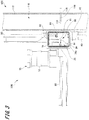
- FIG. 3 is an explanatory view illustrating a state where a plate-like member attached with a fiber sensor is removed from a sample exchange chamber of the charged particle beam device.
- the sample exchange device 200 is provided at a position opposite to the goniometer 118 across the lens barrel 112.
- the position where the sample exchange device 200 is provided is not particularly limited as long as the sample S can be exchanged in the sample chamber 110.
- the sample exchange device 200 includes a sample exchange chamber 30, a sample container 40, a plurality of fiber sensors 50, a sample storage unit 60, a cooling unit 70, a first transport mechanism 80, a second transport mechanism 90, and an evacuation device (not illustrated).
- the sample exchange chamber 30 is a space surrounded by the vacuum container 34.
- the vacuum container 34 is a hollow casing, and the side surface is connected to the lens barrel 112.
- the sample exchange chamber 30 communicates with the sample chamber 110.
- a gate valve (not illustrated) is provided between the sample exchange chamber 30 and the sample chamber 110. This gate valve is used as a vacuum partition between the sample exchange chamber 30 and the sample chamber 110.
- the sample exchange chamber 30 and the sample chamber 110 communicate with each other by opening the gate valve. Further, the sample exchange chamber 30 and the sample chamber 110 are isolated by closing the gate valve.
- the sample exchange chamber 30 is evacuated by the evacuation device (not illustrated).
- the sample container 40 is detachably connected to the bottom surface of the vacuum container 34 via a connection member 42.
- the connection member 42 is formed in a cylindrical shape, one end in the axial direction is continuous with the vacuum container 34, and the sample container 40 is connected to the other end.
- the other end of the connection member 42 and the sample container 40 are sealed with an O-ring.
- the sample container 40 is a container for transporting the cooled sample S.
- the sample S and a refrigerant for cooling the sample S are accommodated.
- the cooled sample S is held by a sample holding member 2 (see FIGS. 4 and 5 ) to be described later, and the sample container 40 accommodates a magazine 4 (to be described later; see FIGS. 6 and 7 ) to which the sample holding member 2 is attached.
- a gate valve is provided between the sample container 40 and the sample exchange chamber 30. The sample container 40 is connected to the sample exchange chamber 30 with the gate valve closed.
- the sample container 40 is evacuated by the evacuation device (not illustrated) with the gate valve closed.
- the refrigerant for example, liquid nitrogen
- the refrigerant for example, liquid nitrogen
- the refrigerant solidifies, solid refrigerant particles (solid nitrogen) with fine particles accumulate, creating gaps between the particles and expanding the volume.
- the refrigerant is surrounded by the heat conducting member. Thereby, even if the refrigerant is solidified, the expansion of the volume can be suppressed, and the solid refrigerant (solid nitrogen) can be prevented from adhering to the magazine 4, the sample holding member 2, and the sample S. Further, after the sample container 40 is evacuated, the gate valve opens, and the sample container 40 and the sample exchange chamber 30 communicate with each other.
- the refrigerant that cools the sample S is, for example, liquid nitrogen.
- the refrigerant may be liquid methane, liquid ethane, or liquid butane.
- the refrigerant is not particularly limited as long as the refrigerant can cool the sample S and is solidified when the sample container 40 is evacuated by the evacuation device (to be described later).
- the plurality of fiber sensors 50 are provided in the sample exchange chamber 30.
- the plurality of fiber sensors 50 includes fiber sensors 50A, 50B, 50C, 50D, and 50E, and are attached to the sample exchange chamber 30 (vacuum container 34) via two plate-like members 35.
- An opening 34a is formed on each of two opposing side surfaces of the vacuum container 34, and the two openings 34a are closed by two plate-like members 35.
- the fiber sensors 50A to 50E are, for example, transmissive photoelectric sensors, and have a projector and a light receiver. When there is a detection target between the projector and the light receiver, the light emitted from the projector is blocked by the detection target, so the fiber sensors 50A to 50E detect that the detection target is present. On the other hand, when there is no detection target between the projector and the light receiver, the light emitted from the projector is received by the light receiver, and thus the fiber sensors 50A to 50E detect that there is no detection target.
- the fiber sensor according to the present invention is not limited to the transmission type, and may be, for example, a reflection type having a light emitter and receiver or a regressive reflection type having a light emitter and receiver and a reflector.
- the fiber sensors 50A and 50B are disposed above the connection portion of the sample container 40 in the sample exchange chamber 30. These fiber sensors 50A and 50B detect whether or not the sample holding member 2 is attached to the magazine 4 (to be described later) transported to the sample exchange chamber 30. The fiber sensors 50A and 50B detect whether or not the sample holding member 2 is attached to a predetermined position of the magazine 4.
- the fiber sensors 50C and 50D are disposed at positions facing a sample storage unit 60 (to be described later; see FIG. 3 ). These fiber sensors 50C and 50D detect whether or not the sample holding member 2 is stored in the sample storage unit 60. Further, the fiber sensors 50C and 50D detect whether or not the sample holding member 2 is stored at a predetermined position of the sample storage unit 60.
- the fiber sensor 50E faces one end of the second transport mechanism 90.
- One end of the second transport mechanism 90 is disposed in the sample exchange chamber 30, and a grip portion 91 that grips the sample holding member 2 is provided at one end of the second transport mechanism 90.
- the fiber sensor 50E detects whether or not the grip portion 91 of the second transport mechanism 90 grips the sample holding member 2.
- the sample storage unit 60 is provided in the sample exchange chamber 30.
- the sample storage unit 60 is cooled by the cooling unit 70. Therefore, the sample storage unit 60 can store the sample S held by the sample holding member 2 in a cooled state.
- the sample storage unit 60 includes a cabinet 61 having a plurality of placement shelves on which a plurality of sample holding members 2 are placed, and a cabinet moving mechanism 62 that moves the cabinet 61 in the vertical direction.
- the cabinet 61 is made of a material having a high thermal conductivity, for example.
- the cabinet moving mechanism 62 moves the cabinet 61 in the vertical direction so that the sample holding member 2 placed on each placement shelf faces the grip portion 91 of the second transport mechanism 90. Thereby, the grip portion 91 of the second transport mechanism 90 can grip the sample holding member 2 placed on the placement shelf.
- the cabinet moving mechanism 62 moves the cabinet 61 in the vertical direction so that the sample holding member 2 placed on each placement shelf faces the fiber sensors 50C and 50D.
- the fiber sensors 50C and 50D detect whether or not the sample holding member 2 is placed (stored) on each placement shelf of the cabinet 61.
- the fiber sensors 50C and 50D detect whether or not the sample holding member 2 is placed (stored) at a predetermined position on each placement shelf of the cabinet 61.
- the cooling unit 70 cools the sample storage unit 60.
- the cooling unit 70 includes, for example, a tank 72 containing a refrigerant (for example, a liquid nitrogen tank containing liquid nitrogen) and a heat conducting member 74 which thermally connects the tank 72, the sample storage unit 60, the first transport mechanism 80, and the second transport mechanism 90.
- the cooling unit 70 cools the sample storage unit 60, the first transport mechanism 80, and the second transport mechanism 90 by cooling the heat conducting member 74 with the refrigerant contained in the tank 72.
- the heat conducting member 74 is, for example, a copper wire.
- the first transport mechanism 80 is described as a specific example of the magazine transport mechanism according to the present invention, and the magazine 4 (the sample holding member 2 that holds the sample S) is transported between the sample container 40 and the sample exchange chamber 30.
- the first transport mechanism 80 holds the magazine 4 accommodated in the sample container 40 and transports the magazine to the sample exchange chamber 30. Further, the first transport mechanism 80 transports the magazine 4 in the sample exchange chamber 30 to the sample container 40.
- the first transport mechanism 80 includes the grip portion 81 that grips the magazine 4, and moves the magazine 4 gripped by the grip portion 81 in the Z direction (vertical direction). That is, the first transport mechanism 80 transports the magazine 4 from the sample container 40 to the sample exchange chamber 30 by gripping the magazine 4 in the sample container 40 and moving the magazine in the +Z direction (upward). The first transport mechanism 80 transports the magazine 4 (sample S) in the sample exchange chamber 30 to the sample container 40 by moving the magazine in the -Z direction (downward).
- the first transport mechanism 80 is cooled by the cooling unit 70. Therefore, even when the first transport mechanism 80 touches the cooled magazine 4, the magazine 4 can maintain the temperature.
- the second transport mechanism 90 transports the sample holding member 2 (sample S) between the magazine 4 gripped by the first transport mechanism 80 and the sample storage unit 60 in the sample exchange chamber 30.
- the second transport mechanism 90 transports the sample holding member 2 to the sample storage unit 60 by gripping the sample holding member 2 attached to the magazine 4 with the grip portion 91 and moving the sample holding member 2 in the horizontal direction.
- the second transport mechanism 90 transports the sample holding member 2 to the magazine 4 gripped by the first transport mechanism 80 by taking out the sample holding member 2 from the sample storage unit 60 and moving the sample holding member 2 in the horizontal direction.
- the second transport mechanism 90 transports the sample holding member 2 between the sample storage unit 60 and the sample chamber 110.
- the second transport mechanism 90 transports the sample holding member 2 to the sample support unit 114 of the sample chamber 110 by taking out the sample holding member 2 from the sample storage unit 60 and moving the sample holding member 2 in the horizontal direction.
- the second transport mechanism 90 transports the sample holding member 2 to the sample storage unit 60 by taking out the sample holding member 2 from the sample support unit 114 of the sample chamber 110 and moving the sample holding member 2 in the horizontal direction.
- the second transport mechanism 90 transports the sample holding member 2 between the magazine 4 gripped by the first transport mechanism 80 and the sample chamber 110 in the sample exchange chamber 30.
- the second transport mechanism 90 transports the sample holding member 2 to the magazine 4 gripped by the first transport mechanism 80 by taking out the sample holding member 2 from the sample support unit 114 of the sample chamber 110 and moving the sample holding member 2 in the horizontal direction.
- the second transport mechanism 90 transports the sample holding member 2 to the sample support unit 114 of the sample chamber 110 by taking out the sample holding member 2 from the magazine 4 gripped by the first transport mechanism 80 and moving the sample holding member 2 in the horizontal direction.
- the second transport mechanism 90 is cooled by the cooling unit 70. Therefore, even when the second transport mechanism 90 touches the cooled sample holding member 2, the sample holding member 2 can maintain the temperature.
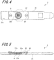
- FIG. 4 is a top view illustrating the sample holding member.
- FIG. 5 is a longitudinal sectional view illustrating a sample holding member.
- the sample holding member 2 is a plate-like member, and is called, for example, a retainer or a cartridge.
- the sample holding member 2 includes a base plate 21 and a fixing piece 22 fixed to the base plate 21.
- the sample holding member 2 is desirably formed of a material having excellent thermal conductivity.
- the base plate 21 is formed of a rectangular plate, and a through hole 21a is formed in a substantially central portion. Further, a recess is formed around the through hole 21a, and the bottom surface of the recess is a sample installation surface 21b (see FIG. 5 ) on which the sample S is installed. Further, a gripping notch 21c (see FIG. 4 ) with which the grip portion 91 of the second transport mechanism 90 is engaged is formed at one end of the base plate 21 in the longitudinal direction.
- the fixing piece 22 is made of a rectangular plate and has a through hole 22a.
- the length of the fixing piece 22 in the short direction is substantially equal to the length of the base plate 21 in the short direction. Further, screw holes are formed at both ends of the fixing piece 22 in the longitudinal direction.
- the fixing piece 22 is fixed to the base plate 21 by a screw 23 that passes through the screw hole.
- the sample S is sandwiched between the fixing piece 22 and the sample installation surface 21b of the base plate 21. Further, in a state where the fixing piece 22 is fixed to the base plate 21, the through hole 22a of the fixing piece 22 faces the through hole 21a of the base plate 21. Therefore, the sample S is interposed between the through hole 21a of the base plate 21 and the through hole 22a of the fixing piece 22.
- the sample S is a sample such as a biological sample or a polymer material of which the structure is easily destroyed by a charged particle beam such as an electron beam or ion beam.
- the sample S is held by the sample holding member 2 after being cooled to, for example, a liquid nitrogen temperature or lower (for example, extremely low temperature).
- the sample holding member 2 holding the sample S is attached to the magazine 4 and stored in the sample container 40.
- the sample holding member 2 holding the sample S is attached to the magazine 4 to be accommodated in the sample container 40, and is transported to the sample exchange chamber 30 by the first transport mechanism 80.
- the sample holding member 2 may be directly accommodated in the sample container 40 without using the magazine 4.
- FIG. 6 is a perspective view illustrating the magazine.
- FIG. 7 is a side view illustrating the magazine.
- the magazine 4 includes a plurality of mounting shelves 25, an upper surface lid 26, and a gripped portion 27.
- the magazine 4 is preferably formed of a material having excellent thermal conductivity.
- Each mounting shelf 25 has a circular portion 25a formed in a disc shape and a flat plate portion 25b continuous to the peripheral surface of the circular portion 25a.
- a recess to which the sample holding member 2 is attached is provided on the upper surface of the circular portion 25a and the flat plate portion 25b.
- the circular portion 25a is provided with two detection holes 28 (one detection hole 28 is illustrated in FIG. 7 ) communicating with the recess to which the sample holding member 2 is attached.
- the two detection holes 28 face each other with the recess to which the sample holding member 2 is attached interposed therebetween. A part of the sample holding member 2 attached to the mounting shelf 25 is exposed from the two detection holes 28.
- the two detection holes 28 in one mounting shelf 25 face the above-described fiber sensor 50B. Therefore, when the sample holding member 2 is attached to a normal position (a predetermined position of the magazine 4) of the mounting shelf 25, the sample holding member 2 is detected by the fiber sensor 50B.
- the sample holding member 2 is not attached to the normal position (predetermined position of the magazine 4) of the mounting shelf 25 or when the sample holding member 2 is not attached to the mounting shelf 25, the sample holding member 2 is not detected by the fiber sensor 50B.
- a notch through which the sample holding member 2 passes is formed in the flat plate portion 25b.
- the detection protrusion 21d of the sample holding member 2 attached to one mounting shelf 25 faces the fiber sensor 50A described above. Therefore, when the sample holding member 2 is attached to the mounting shelf 25, the sample holding member 2 is detected by the fiber sensor 50A. On the other hand, when the sample holding member 2 is not attached to the mounting shelf 25, the sample holding member 2 is not detected by the fiber sensor 50A.
- the sample holding member 2 when the sample holding member 2 is detected by the fiber sensors 50A and 50B, it is determined that the sample holding member 2 is attached to a normal position (a predetermined position of the magazine 4) of the mounting shelf 25. On the other hand, when the sample holding member 2 is not detected by the fiber sensors 50A and 50B, it is determined that the sample holding member 2 is not attached to the mounting shelf 25.
- the sample holding member 2 is detected by the fiber sensor 50A, and the sample holding member 2 is not detected by the fiber sensor 50B, it is determined that the sample holding member 2 is not attached to the normal position of the mounting shelf 25.
- the first transport mechanism 80 causes the detection protrusion 21d of the sample holding member 2 attached to each mounting shelf 25 and the two detection holes 28 of each mounting shelf 25 to sequentially face the fiber sensors 50A and 50B. Thereby, whether or not the sample holding member 2 is attached to each mounting shelf 25, and whether or not the sample holding member 2 is attached to a normal position (predetermined position of the magazine 4) of each mounting shelf 25 can be detected.
- the upper surface lid 26 closes the recess of the uppermost mounting shelf 25 in the plurality of mounting shelves 25.
- the gripped portion 27 is connected to the upper surface lid 26.
- the gripped portion 27 is formed in a cylindrical shape and is gripped by the grip portion 81 (see FIG. 3 ) of the first transport mechanism 80.
- the cabinet 61 of the sample storage unit 60 described above has the same structure as the plurality of mounting shelves 25 of the magazine 4. That is, the detection protrusion 21d of the sample holding member 2 stored in the cabinet 61 faces the fiber sensor 50C. Further, the two detection holes of the cabinet 61 face the fiber sensor 50D. Thereby, whether or not the sample holding member 2 is stored (placed) on each placement shelf of the cabinet 61, and whether or not the sample holding member 2 is stored (placed) at a normal position (the predetermined position of the cabinet 61) of each placement shelf can be detected.
- FIG. 8 is a block diagram illustrating the configuration of the control circuit in the sample exchange device.
- the control circuit in the sample exchange device includes a control unit 201.
- the control unit 201 includes, for example, a microcomputer as a main component, and the microcomputer includes a central processing unit (CPU), a read only memory (ROM), and a random access memory (RAM).
- the ROM stores a control program executed by the CPU, a data table, data for transmitting a control command to the transport mechanism, and the like.
- Various data determined by execution of the control program are stored in the RAM.
- the fiber sensors 50A to 50E are connected to the control unit 201. Each of the fiber sensors 50A to 50E transmits a fiber sensor signal to the control unit 201.
- the control unit 201 receives information on whether or not the sample holding member 2 described above is detected by receiving the fiber sensor signal. Further, the control unit 201 transmits ON/OFF signals to the fiber sensors 50A to 50E, and controls ON/OFF of the fiber sensors 50A to 50E.
- control unit 201 is connected to the drive source of the first transport mechanism 80 and a grip portion detection sensor.
- the grip portion detection sensor of the first transport mechanism 80 detects the position of the grip portion 81 of the first transport mechanism 80 and transmits the position information to the control unit 201.
- control unit 201 transmits a control signal to the drive source of the first transport mechanism 80 to control the driving of the first transport mechanism 80.
- control unit 201 is connected to the drive source of the second transport mechanism 90 and a grip portion detection sensor.
- the grip portion detection sensor of the second transport mechanism 90 detects the position of the grip portion 91 of the second transport mechanism 90 and transmits the position information to the control unit 201.
- control unit 201 transmits a control signal to the drive source of the second transport mechanism 90 to control the driving of the second transport mechanism 90.
- the control unit 201 is connected to the drive source of the sample storage unit 60 and a cabinet detection sensor.
- the cabinet detection sensor of the sample storage unit 60 detects the position of the cabinet 61 and transmits the position information to the control unit 201.
- the control unit 201 transmits a control signal to the drive source of the cabinet moving mechanism 62 in the sample storage unit 60 to control the driving of the cabinet moving mechanism 62.
- the cooled sample S is held by the sample holding member 2. Specifically, the sample S is sandwiched between the base plate 21 and the fixing piece 22 of the sample holding member 2. Note that the sample holding members 2 holding the sample S are prepared as many as needed.
- the sample holding member 2 holding the sample S is attached to the magazine 4. Then, the magazine 4 to which the sample holding member 2 is attached is accommodated in the sample container 40 that is cooled in advance with a refrigerant.
- the sample container 40 is attached to the sample exchange chamber 30 in a state where the sample container 40 is sealed so that air containing external moisture does not enter the sample container 40.
- the sample container 40 is connected to the sample exchange chamber 30 via the connection member 42, and the space between the connection member 42 and the sample container 40 is sealed by an O-ring.
- the sample exchange chamber 30 and the sample container 40 are closed by a gate valve. Note that the inside of the sample exchange chamber 30 is evacuated in advance by the evacuation device and kept in a vacuum.
- the inside of the sample container 40 is evacuated by the evacuation device.
- the refrigerant in the sample container 40 is solidified by raising the freezing point.
- the gate valve between the sample exchange chamber 30 and the sample container 40 is opened. At this time, since the refrigerant in the sample container 40 is solidified, even if the refrigerant remains in the sample container 40, deterioration of the degree of vacuum in the sample exchange chamber 30 can be suppressed.
- the magazine 4 is gripped by the grip portion 81 of the first transport mechanism 80, and the magazine 4 is moved in the +Z direction (upward direction) and transported from the sample container 40 into the sample exchange chamber 30. Then, the gate valve between the sample exchange chamber 30 and the sample container 40 is closed.
- the detection process of the sample holding member 2 attached to the magazine 4 is performed.
- the detection process of the sample holding member 2 it is detected which mounting shelf 25 of the plurality of mounting shelves 25 of the magazine 4 is attached with the sample holding member 2. Further, it is detected whether or not the sample holding member 2 is attached to a normal position of the mounting shelf 25 (a predetermined position of the magazine 4).
- the sample holding member 2 is taken out from the magazine 4 gripped by the grip portion 81 of the first transport mechanism 80 using the grip portion 91 of the second transport mechanism 90. Then, the gate valve between the sample exchange chamber 30 and the sample chamber 110 is opened, the sample holding member 2 is moved in the horizontal direction by the second transport mechanism 90, and the sample holding member 2 (sample S) is introduced in the sample chamber 110. Thereafter, the sample holding member 2 is fixed to the sample support unit 114.
- the sample S can be introduced from the sample container 40 into the sample chamber 110. Then, the second transport mechanism 90 returns to the original position, and the gate valve between the sample exchange chamber 30 and the sample chamber 110 is closed. Thereafter, the sample S is irradiated with the charged particle beam (electron beam) generated by the charged particle beam source 120 (see FIG. 1 ), and the observation of the sample S is started.
- the charged particle beam electrotron beam
- the detection process of the sample holding member 2 in the magazine 4 held by the grip portion 81 of the first transport mechanism 80 is performed. In this process, it is detected which mounting shelf 25 of the plurality of mounting shelves 25 of the magazine 4 is empty (whether the sample holding member 2 is not attached). This process is the same as the detection process of the sample holding member 2.
- the detection process of the sample holding member 2 in the magazine 4 may be omitted.
- the gate valve between the sample exchange chamber 30 and the sample chamber 110 is opened, and the sample holding member 2 (sample S) supported by the sample support unit 114 is gripped using the grip portion 91 of the second transport mechanism 90. Then, the sample holding member 2 (sample S) is moved in the horizontal direction by the second transport mechanism 90 and transferred from the sample chamber 110 to the sample exchange chamber 30.
- the gate valve between the sample exchange chamber 30 and the sample chamber 110 is closed, and the sample holding member 2 gripped by the grip portion 91 of the second transport mechanism 90 is attached to the empty mounting shelf 25 of the magazine 4 gripped by the grip portion 81 of the first transport mechanism 80.
- the inside of the sample container 40 is evacuated by the evacuation device to solidify the refrigerant. Then, the gate valve between the sample exchange chamber 30 and the sample container 40 is opened. At this time, since the refrigerant in the sample container 40 is solidified, the deterioration of the sample exchange chamber 30 in the degree of vacuum can be suppressed even when the refrigerant remains in the sample container 40.
- the magazine 4 is moved in the -Z direction (downward) by the first transport mechanism 80 and transported from the sample exchange chamber 30 into the sample container 40. Thereafter, the gate valve between the sample exchange chamber 30 and the sample container 40 is closed. Thereby, the sample S can be returned from the sample chamber 110 to the sample container 40.
- the sample container 40 is removed from the sample exchange chamber 30 after being returned to atmospheric pressure by vaporization of refrigerant, supply of nitrogen gas, or the like.
- the detection process of the sample holding member 2 in the cabinet 61 of the sample storage unit 60 is performed. In this process, it is detected which placement shelf of the plurality of placement shelves in the cabinet 61 is empty (whether the sample holding member 2 is not stored). This process is the same as the detection process of the sample holding member 2 in the magazine 4.
- the detection process of the sample holding member 2 in the cabinet 61 may be omitted.
- sample S sample S supported by the sample support unit 114 is gripped by the grip portion 91 of the second transport mechanism 90. Then, the sample holding member 2 is moved in the horizontal direction by the second transport mechanism 90 and transferred from the sample chamber 110 to the sample exchange chamber 30.
- the gate valve between the sample exchange chamber 30 and the sample chamber 110 is closed.
- the sample holding member 2 gripped by the grip portion 91 of the second transport mechanism 90 is placed (stored) on an empty placement shelf in the sample storage unit 60.
- the cabinet 61 is moved downward by the cabinet moving mechanism 62 of the sample storage unit 60 so that the empty placement shelf of the cabinet 61 faces the sample holding member 2 (sample S) gripped by the second transport mechanism 90.
- the cabinet 61 is moved upward by the cabinet moving mechanism 62 and returned to a position where the operation of the second transport mechanism 90 is not hindered. Accordingly, the sample S (sample holding member 2) that has been observed can be stored in the sample storage unit 60.
- the sample S stored in the sample storage unit 60 is transported to the sample chamber 110, a procedure reverse to the above-described procedure is performed.
- the detection process of the sample holding member 2 in the cabinet 61 of the sample storage unit 60 is performed.
- the placement shelf, on which the sample holding member 2 is stored (placed), among the plurality of mounting shelves of the cabinet 61 is detected. This process is the same as the detection process of the sample holding member 2 in the magazine 4.
- the detection process of the sample holding member 2 in the cabinet 61 may be omitted.
- the detection process of the sample holding member 2 in the magazine 4 gripped by the grip portion 81 of the first transport mechanism 80 is performed. In this process, it is detected which mounting shelf 25 of the plurality of mounting shelves 25 of the magazine 4 is empty (whether the sample holding member 2 is not attached). This process is the same as the detection process of the sample holding member 2.
- the detection process of the sample holding member 2 in the magazine 4 may be omitted.
- the cabinet 61 is moved downward by the cabinet moving mechanism 62 of the sample storage unit 60, so that the placement shelf on which the sample holding member 2 to be transported to the sample container 40 is stored (loaded) faces the grip portion 91 of the second transport mechanism 90. Then, the sample holding member 2 (sample S) which is stored on the placement shelf of the cabinet 61 is gripped by the grip portion 91 of the second transport mechanism 90.
- the sample holding member 2 gripped by the grip portion 91 of the second transport mechanism 90 is attached to the empty mounting shelf 25 of the magazine 4 gripped by the grip portion 81 of the first transport mechanism 80. Then, the gate valve between the sample exchange chamber 30 and the sample container 40 is opened, the sample holding member 2 is moved in the -Z direction (downward) by the second transport mechanism 90, and the magazine 4 is transported from the sample exchange chamber 30 into the sample container 40.
- the gate valve between the sample exchange chamber 30 and the sample container 40 is closed. Accordingly, the sample S can be returned from the sample storage unit 60 to the sample container 40.
- the sample container 40 is removed from the sample exchange chamber 30 after being returned to atmospheric pressure by vaporization of refrigerant, supply of nitrogen gas, or the like. In a case where the sample S is transported from the sample container 40 to the sample storage unit 60, a procedure reverse to the procedure described above is performed.
- FIG. 9 is a flowchart illustrating an example of the detection process of the sample holding member.
- the control unit 201 determines whether or not the grip portion 81 of the first transport mechanism 80 moves to a specific position (S1). In the process of S1, whether or not the grip portion 81 moves to a specific position is determined based on the position information of the grip portion 81 transmitted from the position detection sensor of the first transport mechanism 80.
- the specific position may be, for example, a position where the grip portion 81 grips the magazine 4 in the sample container 40 or a position where the grip portion 81 enters the sample exchange chamber 30 from the sample container 40. Further, the specific position may be a position where the uppermost mounting shelf 25 in the magazine 4 held by the grip portion 81 faces the fiber sensors 50A and 50B.
- the control unit 201 waits until the grip portion 81 moves to a specific position.
- the control unit 201 turns on the fiber sensors 50A and 50B (S2).
- control unit 201 transmits a control signal to the first transport mechanism 80 and transports the magazine 4 gripped by the grip portion 81 of the first transport mechanism 80 upward to face the fiber sensors 50A and 50B (S3).
- the fiber sensors 50A and 50B transmit the fiber sensor signal regarding the opposite mounting shelf 25 to the control unit 201.
- control unit 201 detects whether or not the sample holding member 2 is attached to the mounting shelf 25 (facing the fiber sensors 50A and 50B) that is a detection target based on the received fiber sensor signal. Further, the control unit 201 detects whether or not the sample holding member 2 is attached to a normal position of the mounting shelf 25 (a predetermined position of the magazine 4) (S4).
- the control unit 201 transmits a control signal for stopping the transportation of the magazine 4 to the first transport mechanism 80.
- the first transport mechanism 80 stops the transportation of the magazine 4 and returns the magazine 4 to the sample container 40.
- the control unit 201 determines whether or not the mounting shelf 25 facing the fiber sensors 50A and 50B is the lowermost mounting shelf 25 (S5). In the process of S5, whether or not the mounting shelf 25 is the lowermost mounting shelf 25 is determined with comparing the number of steps of the mounting shelf 25 stored in the ROM or RAM in advance with the number of the detections of the sample holding member 2, that is, the number of processes of S4.
- the control unit 201 shifts the process to S3. As a result, the control unit 201 causes the mounting shelf 25 at the next step to face the fiber sensors 50A and 50B.
- the control unit 201 turns off the fiber sensors 50A and 50B (S6). After the process of S6, the control unit 201 ends the detection process of the sample holding member 2 in the magazine 4.
- the embodiment described above includes the sample holding member 2 that holds the sample S, the sample exchange chamber 30 that is connected to the sample chamber 110, and the first transport mechanism 80 that has the grip portion 81 for gripping the sample holding member 2 and transports the sample holding member 2 to the sample exchange chamber 30.
- the embodiment includes fiber sensors 50A and 50B that detect whether or not the grip portion 81 of the first transport mechanism 80 grips the sample holding member 2 in the sample exchange chamber 30.
- the fiber sensors 50A and 50B are used to detect whether or not the grip portion 81 of the first transport mechanism 80 grips the sample holding member 2 in a non-contact manner. As a result, the detection unit does not come into contact with the sample holding member 2 and the sample S to transfer heat.
- the fiber sensors 50A and 50B are turned on. Then, after whether or not the grip portion 81 of the first transport mechanism 80 grips the sample holding member 2 is detected, the fiber sensors 50A and 50B are turned off. Thereby, it is possible to shorten the time during which light is emitted from the fiber sensors 50A and 50B, and it is possible to suppress the temperature increase of the sample S due to the light from the fiber sensors 50A and 50B.
- the above-described embodiment includes the sample storage unit 60 that stores the sample holding member 2 transported to the sample exchange chamber 30.
- a plurality of sample holding members 2 samples S
- the plurality of samples S can be introduced into the evacuated sample exchange chamber 30, and the plurality of samples S can be observed to be compared and examined.
- the cooling unit for cooling the sample exchange chamber 30 is provided, the observed sample can be stored in a low-temperature environment, and the observed sample can be observed again.
- the grip portion detection sensor that detects the position of the grip portion 81 of the first transport mechanism 80 is provided, and the fiber sensors 50A and 50B are turned on when the grip portion is transported to a specific position by the grip portion detection sensor.
- the timing at which the fiber sensors 50A and 50B are turned on can always be made constant, and the time during which light is emitted from the fiber sensors 50A and 50B can be easily reduced.
- the above-described embodiment includes the magazine 4 to which the plurality of sample holding members 2 can be attached. Thereby, the plurality of samples can be transported to the sample exchange chamber at one time, and the time required for observing the plurality of samples S can be shortened.
- the fiber sensors 50A and 50B detect whether or not the sample holding member 2 is present and whether or not the sample holding member 2 is attached to the predetermined position (the normal position of the mounting shelf 25) of the magazine 4. Then, when the sample holding member 2 is not attached to the predetermined position of the magazine 4, the transportation of the magazine 4 is stopped. Thereby, it is possible to prevent the sample holding member 2 that is not attached to the predetermined position of the magazine 4 from colliding with the second transport mechanism 90, the sample storage unit 60, and the like in advance. Further, it is possible to prevent the sample holding member 2 from falling from the magazine 4 in advance.
- the above-described embodiment includes the fiber sensors 50C and 50D (fiber sensors for the sample storage unit) that detect whether or not the sample holding member 2 is stored in the sample storage unit 60. Accordingly, it can be determined whether or not the sample holding member 2 can be stored in the sample storage unit 60, and the sample holding member 2 can be stored smoothly.
- the fiber sensors 50C and 50D detect whether or not the sample holding member 2 is present and whether the sample holding member 2 is stored at the predetermined position (the normal position of the placement shelf) of the sample storage unit 60.
- the storage (placement) position of the sample holding member 2 is adjusted by the second transport mechanism 90. Thereby, it is possible to prevent the sample holding member 2 from falling from the sample storage unit 60 in advance.
- the fiber sensor 50E detects whether or not the grip portion 91 of the second transport mechanism 90 grips the sample holding member 2 stored in the sample storage unit 60. Thus, after it is confirmed that the grip portion 91 of the second transport mechanism 90 grips the sample holding member 2, the sample holding member 2 can be transported. Further, after it is confirmed that the grip portion 91 of the second transport mechanism 90 does not grip the sample holding member 2, it is possible to perform driving for taking out the sample holding member 2 from the magazine 4.
- the present invention is not limited to the above-described embodiments, and various modifications can be made without departing from the spirit of the invention described in the claims.
- the transmission electron microscope has been described as an example of the charged particle beam device.
- the charged particle beam device according to the present invention is not particularly limited as long as the device uses a charged particle beam such as electrons and ions. That is, the charged particle beam device according to the present invention may be an electron microscope such as a scanning transmission electron microscope and a scanning electron microscope, an electron probe micro analyzer, a focused ion beam apparatus, an electron beam exposure apparatus, or the like.
- the plurality of fiber sensors 50A to 50E are provided on the plate-like member 35 that can be attached to and detached from the sample exchange chamber 30 (vacuum container 34).
- the fiber sensor according to the present invention is not limited to the one attached to the sample exchange chamber 30 (vacuum container 34) via the plate-like member 35.
- the fiber sensor may be one attached directly to the sample exchange chamber 30 (vacuum container 34).
- a plurality of plate-like members having different positions at which the fiber sensor is fixed may be provided.
- the position of the fiber sensor can be easily changed by changing the plate-like member, the sample holding member can be easily detected even if the size of the sample holding member or the mounting position of the sample holding member with respect to the magazine 4 is changed.
Landscapes
- Chemical & Material Sciences (AREA)
- Analytical Chemistry (AREA)
- Analysing Materials By The Use Of Radiation (AREA)
- Sampling And Sample Adjustment (AREA)
Abstract
Description
- The present invention relates to a sample exchange device and a charged particle beam device.
- In a case where a sample is observed with a charged particle beam device such as an electron microscope, when a sample such as a biological sample or a polymer material is irradiated with a charged particle beam such as an electron beam, the structure of the sample may be destroyed so that the sample in a normal state cannot be observed. In this case, for example, when the sample is cooled below a liquid nitrogen temperature (for example, extremely low temperature), even if the sample is irradiated with a charged particle beam such as an electron beam, the sample is difficult to break, and the sample in a normal state cannot be observed.
- For example,
JP 2015-88237 A JP 2015-88237 A - However, in the charged particle beam device described in
JP 2015-88237 A - Accordingly, the present invention is made in consideration of the actual situation in the above related art, and an object is to provide a sample exchange device and a charged particle beam device capable of detecting whether or not a sample holding member is gripped by a transport mechanism in a sample exchange chamber.
- In order to achieve the above object, a sample exchange device of the present invention includes:
- a sample holding member that holds the sample;
- a sample exchange chamber that is connected to a sample chamber;
- a first transport mechanism that includes a grip portion for gripping the sample holding member and transports the sample holding member to the sample exchange chamber;
- a cooling unit that cools the sample exchange chamber;
- a fiber sensor that detects whether or not the grip portion of the first transport mechanism grips the sample holding member in the sample exchange chamber;
- a control unit that controls ON/OFF of the fiber sensor;
- a sample storage unit that stores the sample holding member transported to the sample exchange chamber; and
- a second transport mechanism that transports the sample holding member transported to the sample exchange chamber to the sample chamber.
- The control unit turns on the fiber sensor when the grip portion of the first transport mechanism enters the sample exchange chamber and turns off the fiber sensor after it is detected whether or not the grip portion of the first transport mechanism grips the sample holding member.
- In order to achieve the above object, a charged particle beam device of the present invention includes:
- a sample chamber that is evacuated; and
- the sample exchange device that is connected to the sample chamber.
- According to the present invention, it is possible to detect whether or not the sample holding member is gripped by the transport mechanism in the sample exchange chamber.
-
-
FIG. 1 is a schematic configuration diagram illustrating a charged particle beam device according to this embodiment; -
FIG. 2 is an explanatory view illustrating an example of a main part of the charged particle beam device according to this embodiment; -
FIG. 3 is an explanatory view illustrating a state where a plate-like member attached with a fiber sensor is removed from a sample exchange chamber of the charged particle beam device according to this embodiment; -
FIG. 4 is a top view illustrating a sample holding member of the charged particle beam device according to this embodiment; -
FIG. 5 is a longitudinal sectional view illustrating the sample holding member of the charged particle beam device according to this embodiment; -
FIG. 6 is a perspective view illustrating a magazine of the charged particle beam device according to this embodiment; -
FIG. 7 is a side view illustrating the magazine of the charged particle beam device according to this embodiment; -
FIG. 8 is a block diagram illustrating a configuration of a control circuit in the sample exchange device according to this embodiment; and -
FIG. 9 is a flowchart illustrating an example of an ON/OFF process of a fiber sensor in the sample exchange device according to this embodiment. - Hereinafter, modes for carrying out the present invention (hereinafter referred to as "embodiments") will be described in detail with reference to the drawings. The present invention is not limited to the embodiments, and various numerical values in the embodiments are examples. In this specification and drawings, the same components or components having substantially the same function are denoted by the same reference numerals, and redundant description is omitted.
- Before describing a sample exchange device of the present invention, a charged particle beam device of the present invention including the sample exchange device will be described. Here, an example of a transmission electron microscope will be described as the charged particle beam device of the present invention.
FIG. 1 is a schematic configuration diagram illustrating a charged particle beam device of the present invention. - As illustrated in
FIG. 1 , a chargedparticle beam device 100 includes asample chamber 110, a chargedparticle beam source 120, anoptical system 130, animaging device 140, and asample exchange device 200. The chargedparticle beam device 100 is installed on agantry 160 via avibration isolator 150. - The
sample chamber 110 includes alens barrel 112, and is a space defined by the inner wall of thelens barrel 112. In other words, thelens barrel 112 may be a vacuum container including thesample chamber 110. The inside of thesample chamber 110 is evacuated by an evacuation device (not illustrated). Thereby, thesample chamber 110 is kept in a vacuum. - Here, the vacuum means a space state where the pressure is lower than the atmospheric pressure. Moreover, evacuation means exhausting internal gas in order to obtain the target vacuum state. As the evacuation device for evacuating the
sample chamber 110, for example, an ion pump, a scroll pump, or a turbo molecular pump can be used. - In the
sample chamber 110, asample support unit 114 that supports a sample S is disposed. Thesample support unit 114 is provided at the tip of asample holder 116. Agoniometer 118 positions the sample S supported by thesample support unit 114 in thesample chamber 110. Here, thesample support unit 114 supports the sample S by supporting asample holding member 2 holding the sample S. - The
sample chamber 110 is a space where the sample S is irradiated with a charged particle beam (electron beam). In the chargedparticle beam device 100, thesample chamber 110 irradiates the sample S supported by thesample support unit 114 with an electron beam. The electron beam transmitted through the sample S is imaged by theoptical system 130, and an electron microscope image is obtained. - The charged
particle beam source 120 generates an electron beam (charged particle beam) EB. As the chargedparticle beam source 120, for example, a known electron gun can be used. The electron gun used as the chargedparticle beam source 120 is not particularly limited, and for example, an electron gun such as a thermionic emission type electron gun, a thermal field emission type electron gun, and a cold cathode field emission type electron gun can be used. - The
optical system 130 includes anirradiation lens 132 for irradiating the sample S with an electron beam EB, anobjective lens 134, anintermediate lens 136, and aprojection lens 138 configuring an imaging system for forming an image with the electron beam EB transmitted through the sample S. - The
imaging device 140 images an electron microscope image formed by the imaging system (lenses imaging device 140 has, for example, a charged-coupled devices (CCD) camera having a solid-state imaging device disposed two-dimensionally, images an electron microscope image, and outputs information of the electron microscope image. - Next, the configuration of the
sample exchange device 200 will be described with reference toFIGS. 2 and3 . -
FIG. 2 is an explanatory view illustrating an example of a main part of the charged particle beam device.FIG. 3 is an explanatory view illustrating a state where a plate-like member attached with a fiber sensor is removed from a sample exchange chamber of the charged particle beam device. - As illustrated in
FIGS. 2 and3 , thesample exchange device 200 is provided at a position opposite to thegoniometer 118 across thelens barrel 112. The position where thesample exchange device 200 is provided is not particularly limited as long as the sample S can be exchanged in thesample chamber 110. - The
sample exchange device 200 includes asample exchange chamber 30, asample container 40, a plurality offiber sensors 50, asample storage unit 60, a coolingunit 70, afirst transport mechanism 80, asecond transport mechanism 90, and an evacuation device (not illustrated). - The
sample exchange chamber 30 is a space surrounded by thevacuum container 34. Thevacuum container 34 is a hollow casing, and the side surface is connected to thelens barrel 112. Thesample exchange chamber 30 communicates with thesample chamber 110. - A gate valve (not illustrated) is provided between the
sample exchange chamber 30 and thesample chamber 110. This gate valve is used as a vacuum partition between thesample exchange chamber 30 and thesample chamber 110. Thesample exchange chamber 30 and thesample chamber 110 communicate with each other by opening the gate valve. Further, thesample exchange chamber 30 and thesample chamber 110 are isolated by closing the gate valve. Thesample exchange chamber 30 is evacuated by the evacuation device (not illustrated). - The
sample container 40 is detachably connected to the bottom surface of thevacuum container 34 via aconnection member 42. Theconnection member 42 is formed in a cylindrical shape, one end in the axial direction is continuous with thevacuum container 34, and thesample container 40 is connected to the other end. The other end of theconnection member 42 and thesample container 40 are sealed with an O-ring. - The
sample container 40 is a container for transporting the cooled sample S. In thesample container 40, the sample S and a refrigerant for cooling the sample S are accommodated. The cooled sample S is held by a sample holding member 2 (seeFIGS. 4 and 5 ) to be described later, and thesample container 40 accommodates a magazine 4 (to be described later; seeFIGS. 6 and 7 ) to which thesample holding member 2 is attached. A gate valve is provided between thesample container 40 and thesample exchange chamber 30. Thesample container 40 is connected to thesample exchange chamber 30 with the gate valve closed. - The
sample container 40 is evacuated by the evacuation device (not illustrated) with the gate valve closed. Thereby, the refrigerant (for example, liquid nitrogen) accommodated in thesample container 40 is solidified by raising the freezing point. As the refrigerant solidifies, solid refrigerant particles (solid nitrogen) with fine particles accumulate, creating gaps between the particles and expanding the volume. - In the
sample container 40, the refrigerant is surrounded by the heat conducting member. Thereby, even if the refrigerant is solidified, the expansion of the volume can be suppressed, and the solid refrigerant (solid nitrogen) can be prevented from adhering to themagazine 4, thesample holding member 2, and the sample S. Further, after thesample container 40 is evacuated, the gate valve opens, and thesample container 40 and thesample exchange chamber 30 communicate with each other. - The refrigerant that cools the sample S is, for example, liquid nitrogen. The refrigerant may be liquid methane, liquid ethane, or liquid butane. The refrigerant is not particularly limited as long as the refrigerant can cool the sample S and is solidified when the
sample container 40 is evacuated by the evacuation device (to be described later). - As illustrated in
FIG. 2 , the plurality offiber sensors 50 are provided in thesample exchange chamber 30. The plurality offiber sensors 50 includesfiber sensors like members 35. Anopening 34a is formed on each of two opposing side surfaces of thevacuum container 34, and the twoopenings 34a are closed by two plate-like members 35. - The
fiber sensors 50A to 50E are, for example, transmissive photoelectric sensors, and have a projector and a light receiver. When there is a detection target between the projector and the light receiver, the light emitted from the projector is blocked by the detection target, so thefiber sensors 50A to 50E detect that the detection target is present. On the other hand, when there is no detection target between the projector and the light receiver, the light emitted from the projector is received by the light receiver, and thus thefiber sensors 50A to 50E detect that there is no detection target. - The fiber sensor according to the present invention is not limited to the transmission type, and may be, for example, a reflection type having a
light emitter and receiver or a regressive reflection type having a light emitter and receiver and a reflector. - The
fiber sensors sample container 40 in thesample exchange chamber 30. Thesefiber sensors sample holding member 2 is attached to the magazine 4 (to be described later) transported to thesample exchange chamber 30. Thefiber sensors sample holding member 2 is attached to a predetermined position of themagazine 4. - The
fiber sensors FIG. 3 ). Thesefiber sensors sample holding member 2 is stored in thesample storage unit 60. Further, thefiber sensors sample holding member 2 is stored at a predetermined position of thesample storage unit 60. - Further, the
fiber sensor 50E faces one end of thesecond transport mechanism 90. One end of thesecond transport mechanism 90 is disposed in thesample exchange chamber 30, and agrip portion 91 that grips thesample holding member 2 is provided at one end of thesecond transport mechanism 90. Thefiber sensor 50E detects whether or not thegrip portion 91 of thesecond transport mechanism 90 grips thesample holding member 2. - As illustrated in
FIG. 3 , thesample storage unit 60 is provided in thesample exchange chamber 30. Thesample storage unit 60 is cooled by the coolingunit 70. Therefore, thesample storage unit 60 can store the sample S held by thesample holding member 2 in a cooled state. Thesample storage unit 60 includes acabinet 61 having a plurality of placement shelves on which a plurality ofsample holding members 2 are placed, and acabinet moving mechanism 62 that moves thecabinet 61 in the vertical direction. Thecabinet 61 is made of a material having a high thermal conductivity, for example. - The
cabinet moving mechanism 62 moves thecabinet 61 in the vertical direction so that thesample holding member 2 placed on each placement shelf faces thegrip portion 91 of thesecond transport mechanism 90. Thereby, thegrip portion 91 of thesecond transport mechanism 90 can grip thesample holding member 2 placed on the placement shelf. - Further, the
cabinet moving mechanism 62 moves thecabinet 61 in the vertical direction so that thesample holding member 2 placed on each placement shelf faces thefiber sensors fiber sensors sample holding member 2 is placed (stored) on each placement shelf of thecabinet 61. Thefiber sensors sample holding member 2 is placed (stored) at a predetermined position on each placement shelf of thecabinet 61. - The cooling
unit 70 cools thesample storage unit 60. The coolingunit 70 includes, for example, atank 72 containing a refrigerant (for example, a liquid nitrogen tank containing liquid nitrogen) and aheat conducting member 74 which thermally connects thetank 72, thesample storage unit 60, thefirst transport mechanism 80, and thesecond transport mechanism 90. The coolingunit 70 cools thesample storage unit 60, thefirst transport mechanism 80, and thesecond transport mechanism 90 by cooling theheat conducting member 74 with the refrigerant contained in thetank 72. Theheat conducting member 74 is, for example, a copper wire. - The
first transport mechanism 80 is described as a specific example of the magazine transport mechanism according to the present invention, and the magazine 4 (thesample holding member 2 that holds the sample S) is transported between thesample container 40 and thesample exchange chamber 30. Thefirst transport mechanism 80 holds themagazine 4 accommodated in thesample container 40 and transports the magazine to thesample exchange chamber 30. Further, thefirst transport mechanism 80 transports themagazine 4 in thesample exchange chamber 30 to thesample container 40. - As illustrated in
FIG. 3 , thefirst transport mechanism 80 includes thegrip portion 81 that grips themagazine 4, and moves themagazine 4 gripped by thegrip portion 81 in the Z direction (vertical direction). That is, thefirst transport mechanism 80 transports themagazine 4 from thesample container 40 to thesample exchange chamber 30 by gripping themagazine 4 in thesample container 40 and moving the magazine in the +Z direction (upward). Thefirst transport mechanism 80 transports the magazine 4 (sample S) in thesample exchange chamber 30 to thesample container 40 by moving the magazine in the -Z direction (downward). - As described above, the
first transport mechanism 80 is cooled by the coolingunit 70. Therefore, even when thefirst transport mechanism 80 touches the cooledmagazine 4, themagazine 4 can maintain the temperature. - The
second transport mechanism 90 transports the sample holding member 2 (sample S) between themagazine 4 gripped by thefirst transport mechanism 80 and thesample storage unit 60 in thesample exchange chamber 30. Thesecond transport mechanism 90 transports thesample holding member 2 to thesample storage unit 60 by gripping thesample holding member 2 attached to themagazine 4 with thegrip portion 91 and moving thesample holding member 2 in the horizontal direction. Thesecond transport mechanism 90 transports thesample holding member 2 to themagazine 4 gripped by thefirst transport mechanism 80 by taking out thesample holding member 2 from thesample storage unit 60 and moving thesample holding member 2 in the horizontal direction. - Further, the
second transport mechanism 90 transports thesample holding member 2 between thesample storage unit 60 and thesample chamber 110. Thesecond transport mechanism 90 transports thesample holding member 2 to thesample support unit 114 of thesample chamber 110 by taking out thesample holding member 2 from thesample storage unit 60 and moving thesample holding member 2 in the horizontal direction. Further, thesecond transport mechanism 90 transports thesample holding member 2 to thesample storage unit 60 by taking out thesample holding member 2 from thesample support unit 114 of thesample chamber 110 and moving thesample holding member 2 in the horizontal direction. - The
second transport mechanism 90 transports thesample holding member 2 between themagazine 4 gripped by thefirst transport mechanism 80 and thesample chamber 110 in thesample exchange chamber 30. Thesecond transport mechanism 90 transports thesample holding member 2 to themagazine 4 gripped by thefirst transport mechanism 80 by taking out thesample holding member 2 from thesample support unit 114 of thesample chamber 110 and moving thesample holding member 2 in the horizontal direction. Further, thesecond transport mechanism 90 transports thesample holding member 2 to thesample support unit 114 of thesample chamber 110 by taking out thesample holding member 2 from themagazine 4 gripped by thefirst transport mechanism 80 and moving thesample holding member 2 in the horizontal direction. - As described above, the
second transport mechanism 90 is cooled by the coolingunit 70. Therefore, even when thesecond transport mechanism 90 touches the cooledsample holding member 2, thesample holding member 2 can maintain the temperature. - Next, the sample holding member will be described with reference to
FIGS. 4 and 5 . -
FIG. 4 is a top view illustrating the sample holding member.FIG. 5 is a longitudinal sectional view illustrating a sample holding member. - As illustrated in
FIGS. 4 and 5 , thesample holding member 2 is a plate-like member, and is called, for example, a retainer or a cartridge. Thesample holding member 2 includes abase plate 21 and a fixingpiece 22 fixed to thebase plate 21. Note that thesample holding member 2 is desirably formed of a material having excellent thermal conductivity. - The
base plate 21 is formed of a rectangular plate, and a throughhole 21a is formed in a substantially central portion. Further, a recess is formed around the throughhole 21a, and the bottom surface of the recess is asample installation surface 21b (seeFIG. 5 ) on which the sample S is installed. Further, a grippingnotch 21c (seeFIG. 4 ) with which thegrip portion 91 of thesecond transport mechanism 90 is engaged is formed at one end of thebase plate 21 in the longitudinal direction. - The fixing
piece 22 is made of a rectangular plate and has a throughhole 22a. The length of the fixingpiece 22 in the short direction is substantially equal to the length of thebase plate 21 in the short direction. Further, screw holes are formed at both ends of the fixingpiece 22 in the longitudinal direction. The fixingpiece 22 is fixed to thebase plate 21 by ascrew 23 that passes through the screw hole. - When the fixing
piece 22 is fixed to thebase plate 21, the sample S is sandwiched between the fixingpiece 22 and thesample installation surface 21b of thebase plate 21. Further, in a state where the fixingpiece 22 is fixed to thebase plate 21, the throughhole 22a of the fixingpiece 22 faces the throughhole 21a of thebase plate 21. Therefore, the sample S is interposed between the throughhole 21a of thebase plate 21 and the throughhole 22a of the fixingpiece 22. - For example, the sample S is a sample such as a biological sample or a polymer material of which the structure is easily destroyed by a charged particle beam such as an electron beam or ion beam. Further, the sample S is held by the
sample holding member 2 after being cooled to, for example, a liquid nitrogen temperature or lower (for example, extremely low temperature). Thesample holding member 2 holding the sample S is attached to themagazine 4 and stored in thesample container 40. - In this embodiment, the
sample holding member 2 holding the sample S is attached to themagazine 4 to be accommodated in thesample container 40, and is transported to thesample exchange chamber 30 by thefirst transport mechanism 80. However, in the sample exchange device and the charged particle beam device according to the present invention, thesample holding member 2 may be directly accommodated in thesample container 40 without using themagazine 4. - Next, the magazine will be described with reference to
FIGS. 6 and 7 . -
FIG. 6 is a perspective view illustrating the magazine.FIG. 7 is a side view illustrating the magazine. - As illustrated in
FIGS. 6 and 7 , themagazine 4 includes a plurality of mountingshelves 25, anupper surface lid 26, and a grippedportion 27. Note that themagazine 4 is preferably formed of a material having excellent thermal conductivity. - The plurality of mounting
shelves 25 are connected in an overlapping manner in the vertical direction. Each mountingshelf 25 has acircular portion 25a formed in a disc shape and aflat plate portion 25b continuous to the peripheral surface of thecircular portion 25a. A recess to which thesample holding member 2 is attached is provided on the upper surface of thecircular portion 25a and theflat plate portion 25b. - As illustrated in
FIG. 7 , thecircular portion 25a is provided with two detection holes 28 (onedetection hole 28 is illustrated inFIG. 7 ) communicating with the recess to which thesample holding member 2 is attached. The twodetection holes 28 face each other with the recess to which thesample holding member 2 is attached interposed therebetween. A part of thesample holding member 2 attached to the mountingshelf 25 is exposed from the two detection holes 28. - When the
magazine 4 is disposed at a predetermined position in thesample exchange chamber 30 by thefirst transport mechanism 80, the twodetection holes 28 in one mountingshelf 25 face the above-describedfiber sensor 50B. Therefore, when thesample holding member 2 is attached to a normal position (a predetermined position of the magazine 4) of the mountingshelf 25, thesample holding member 2 is detected by thefiber sensor 50B. - On the other hand, when the
sample holding member 2 is not attached to the normal position (predetermined position of the magazine 4) of the mountingshelf 25 or when thesample holding member 2 is not attached to the mountingshelf 25, thesample holding member 2 is not detected by thefiber sensor 50B. - A notch through which the
sample holding member 2 passes is formed in theflat plate portion 25b. As a result, when thesample holding member 2 is attached to the mountingshelf 25, one end (on thegripping notch 21c side) of thebase plate 21 of thesample holding member 2 in the longitudinal direction projects from the notch of theflat plate portion 25b to the outside of the mountingshelf 25. Hereinafter, a portion of thesample holding member 2 that protrudes outside the mountingshelf 25 is referred to as adetection protrusion 21d. - When the
magazine 4 is disposed at a predetermined position in thesample exchange chamber 30 by the first transport mechanism 80 (seeFIG. 2 ), thedetection protrusion 21d of thesample holding member 2 attached to one mountingshelf 25 faces thefiber sensor 50A described above. Therefore, when thesample holding member 2 is attached to the mountingshelf 25, thesample holding member 2 is detected by thefiber sensor 50A. On the other hand, when thesample holding member 2 is not attached to the mountingshelf 25, thesample holding member 2 is not detected by thefiber sensor 50A. - For example, when the
sample holding member 2 is detected by thefiber sensors sample holding member 2 is attached to a normal position (a predetermined position of the magazine 4) of the mountingshelf 25. On the other hand, when thesample holding member 2 is not detected by thefiber sensors sample holding member 2 is not attached to the mountingshelf 25. - Further, when the
sample holding member 2 is detected by thefiber sensor 50A, and thesample holding member 2 is not detected by thefiber sensor 50B, it is determined that thesample holding member 2 is not attached to the normal position of the mountingshelf 25. - Note that the
first transport mechanism 80 causes thedetection protrusion 21d of thesample holding member 2 attached to each mountingshelf 25 and the twodetection holes 28 of each mountingshelf 25 to sequentially face thefiber sensors sample holding member 2 is attached to each mountingshelf 25, and whether or not thesample holding member 2 is attached to a normal position (predetermined position of the magazine 4) of each mountingshelf 25 can be detected. - The
upper surface lid 26 closes the recess of theuppermost mounting shelf 25 in the plurality of mountingshelves 25. Thus, the sample S held by thesample holding member 2 can be covered and protected by theupper surface lid 26. The grippedportion 27 is connected to theupper surface lid 26. The grippedportion 27 is formed in a cylindrical shape and is gripped by the grip portion 81 (seeFIG. 3 ) of thefirst transport mechanism 80. - Note that the
cabinet 61 of thesample storage unit 60 described above has the same structure as the plurality of mountingshelves 25 of themagazine 4. That is, thedetection protrusion 21d of thesample holding member 2 stored in thecabinet 61 faces thefiber sensor 50C. Further, the two detection holes of thecabinet 61 face thefiber sensor 50D. Thereby, whether or not thesample holding member 2 is stored (placed) on each placement shelf of thecabinet 61, and whether or not thesample holding member 2 is stored (placed) at a normal position (the predetermined position of the cabinet 61) of each placement shelf can be detected. - Next, the configuration of the control circuit in the sample exchange device will be described with reference to
FIG. 8 . -
FIG. 8 is a block diagram illustrating the configuration of the control circuit in the sample exchange device. - As illustrated in
FIG. 8 , the control circuit in the sample exchange device includes acontrol unit 201. Thecontrol unit 201 includes, for example, a microcomputer as a main component, and the microcomputer includes a central processing unit (CPU), a read only memory (ROM), and a random access memory (RAM). The ROM stores a control program executed by the CPU, a data table, data for transmitting a control command to the transport mechanism, and the like. Various data determined by execution of the control program are stored in the RAM. - The
fiber sensors 50A to 50E are connected to thecontrol unit 201. Each of thefiber sensors 50A to 50E transmits a fiber sensor signal to thecontrol unit 201. Thecontrol unit 201 receives information on whether or not thesample holding member 2 described above is detected by receiving the fiber sensor signal. Further, thecontrol unit 201 transmits ON/OFF signals to thefiber sensors 50A to 50E, and controls ON/OFF of thefiber sensors 50A to 50E. - Further, the
control unit 201 is connected to the drive source of thefirst transport mechanism 80 and a grip portion detection sensor. The grip portion detection sensor of thefirst transport mechanism 80 detects the position of thegrip portion 81 of thefirst transport mechanism 80 and transmits the position information to thecontrol unit 201. In addition, thecontrol unit 201 transmits a control signal to the drive source of thefirst transport mechanism 80 to control the driving of thefirst transport mechanism 80. - Further, the
control unit 201 is connected to the drive source of thesecond transport mechanism 90 and a grip portion detection sensor. The grip portion detection sensor of thesecond transport mechanism 90 detects the position of thegrip portion 91 of thesecond transport mechanism 90 and transmits the position information to thecontrol unit 201. In addition, thecontrol unit 201 transmits a control signal to the drive source of thesecond transport mechanism 90 to control the driving of thesecond transport mechanism 90. - The
control unit 201 is connected to the drive source of thesample storage unit 60 and a cabinet detection sensor. The cabinet detection sensor of thesample storage unit 60 detects the position of thecabinet 61 and transmits the position information to thecontrol unit 201. In addition, thecontrol unit 201 transmits a control signal to the drive source of thecabinet moving mechanism 62 in thesample storage unit 60 to control the driving of thecabinet moving mechanism 62. - Next, the operation of the charged
particle beam device 100 will be described. - First, a method for introducing the sample S from the
sample container 40 into thesample chamber 110 will be described. - First, the cooled sample S is held by the
sample holding member 2. Specifically, the sample S is sandwiched between thebase plate 21 and the fixingpiece 22 of thesample holding member 2. Note that thesample holding members 2 holding the sample S are prepared as many as needed. - Next, the
sample holding member 2 holding the sample S is attached to themagazine 4. Then, themagazine 4 to which thesample holding member 2 is attached is accommodated in thesample container 40 that is cooled in advance with a refrigerant. - Next, the
sample container 40 is attached to thesample exchange chamber 30 in a state where thesample container 40 is sealed so that air containing external moisture does not enter thesample container 40. At this time, thesample container 40 is connected to thesample exchange chamber 30 via theconnection member 42, and the space between theconnection member 42 and thesample container 40 is sealed by an O-ring. Thesample exchange chamber 30 and thesample container 40 are closed by a gate valve. Note that the inside of thesample exchange chamber 30 is evacuated in advance by the evacuation device and kept in a vacuum. - Next, the inside of the
sample container 40 is evacuated by the evacuation device. When the inside of thesample container 40 is evacuated, the refrigerant in thesample container 40 is solidified by raising the freezing point. Next, the gate valve between thesample exchange chamber 30 and thesample container 40 is opened. At this time, since the refrigerant in thesample container 40 is solidified, even if the refrigerant remains in thesample container 40, deterioration of the degree of vacuum in thesample exchange chamber 30 can be suppressed. - Next, the
magazine 4 is gripped by thegrip portion 81 of thefirst transport mechanism 80, and themagazine 4 is moved in the +Z direction (upward direction) and transported from thesample container 40 into thesample exchange chamber 30. Then, the gate valve between thesample exchange chamber 30 and thesample container 40 is closed. - Next, the detection process of the
sample holding member 2 attached to themagazine 4 is performed. In the detection process of thesample holding member 2, it is detected which mountingshelf 25 of the plurality of mountingshelves 25 of themagazine 4 is attached with thesample holding member 2. Further, it is detected whether or not thesample holding member 2 is attached to a normal position of the mounting shelf 25 (a predetermined position of the magazine 4). - Next, the
sample holding member 2 is taken out from themagazine 4 gripped by thegrip portion 81 of thefirst transport mechanism 80 using thegrip portion 91 of thesecond transport mechanism 90. Then, the gate valve between thesample exchange chamber 30 and thesample chamber 110 is opened, thesample holding member 2 is moved in the horizontal direction by thesecond transport mechanism 90, and the sample holding member 2 (sample S) is introduced in thesample chamber 110. Thereafter, thesample holding member 2 is fixed to thesample support unit 114. - Thereby, the sample S can be introduced from the
sample container 40 into thesample chamber 110. Then, thesecond transport mechanism 90 returns to the original position, and the gate valve between thesample exchange chamber 30 and thesample chamber 110 is closed. Thereafter, the sample S is irradiated with the charged particle beam (electron beam) generated by the charged particle beam source 120 (seeFIG. 1 ), and the observation of the sample S is started. - Next, a process of taking the sample S from the
sample chamber 110 and returning the sample to thesample container 40 will be described. - First, the detection process of the
sample holding member 2 in themagazine 4 held by thegrip portion 81 of thefirst transport mechanism 80 is performed. In this process, it is detected which mountingshelf 25 of the plurality of mountingshelves 25 of themagazine 4 is empty (whether thesample holding member 2 is not attached). This process is the same as the detection process of thesample holding member 2. - If the
sample holding member 2 is not attached to themagazine 4 after the above-described detection process of thesample holding member 2, which mountingshelf 25 is empty is determined from the information obtained in the detection process of thesample holding member 2. In this case, the detection process of thesample holding member 2 in themagazine 4 may be omitted. - Next, the gate valve between the
sample exchange chamber 30 and thesample chamber 110 is opened, and the sample holding member 2 (sample S) supported by thesample support unit 114 is gripped using thegrip portion 91 of thesecond transport mechanism 90. Then, the sample holding member 2 (sample S) is moved in the horizontal direction by thesecond transport mechanism 90 and transferred from thesample chamber 110 to thesample exchange chamber 30. - Next, the gate valve between the
sample exchange chamber 30 and thesample chamber 110 is closed, and thesample holding member 2 gripped by thegrip portion 91 of thesecond transport mechanism 90 is attached to theempty mounting shelf 25 of themagazine 4 gripped by thegrip portion 81 of thefirst transport mechanism 80. - Next, the inside of the
sample container 40 is evacuated by the evacuation device to solidify the refrigerant. Then, the gate valve between thesample exchange chamber 30 and thesample container 40 is opened. At this time, since the refrigerant in thesample container 40 is solidified, the deterioration of thesample exchange chamber 30 in the degree of vacuum can be suppressed even when the refrigerant remains in thesample container 40. - Next, the
magazine 4 is moved in the -Z direction (downward) by thefirst transport mechanism 80 and transported from thesample exchange chamber 30 into thesample container 40. Thereafter, the gate valve between thesample exchange chamber 30 and thesample container 40 is closed. Thereby, the sample S can be returned from thesample chamber 110 to thesample container 40. Note that thesample container 40 is removed from thesample exchange chamber 30 after being returned to atmospheric pressure by vaporization of refrigerant, supply of nitrogen gas, or the like. - Next, a method for using the
sample storage unit 60 will be described. Here, a case where the sample S in thesample chamber 110 that has been observed is stored in thesample storage unit 60 and a case where the sample S stored in thesample storage unit 60 is transported to thesample container 40 will be described. - When the sample S in the
sample chamber 110 that has been observed is stored in thesample storage unit 60, first, the detection process of thesample holding member 2 in thecabinet 61 of thesample storage unit 60 is performed. In this process, it is detected which placement shelf of the plurality of placement shelves in thecabinet 61 is empty (whether thesample holding member 2 is not stored). This process is the same as the detection process of thesample holding member 2 in themagazine 4. - Note that if it is known which mounting shelf of the plurality of placement shelves in the
cabinet 61 is empty (the storage area stores the empty information of the placement shelf), the detection process of thesample holding member 2 in thecabinet 61 may be omitted. - Next, the gate valve between the
sample exchange chamber 30 and thesample chamber 110 is opened. Next, the sample holding member 2 (sample S) supported by thesample support unit 114 is gripped by thegrip portion 91 of thesecond transport mechanism 90. Then, thesample holding member 2 is moved in the horizontal direction by thesecond transport mechanism 90 and transferred from thesample chamber 110 to thesample exchange chamber 30. - Next, the gate valve between the
sample exchange chamber 30 and thesample chamber 110 is closed. Next, thesample holding member 2 gripped by thegrip portion 91 of thesecond transport mechanism 90 is placed (stored) on an empty placement shelf in thesample storage unit 60. At this time, thecabinet 61 is moved downward by thecabinet moving mechanism 62 of thesample storage unit 60 so that the empty placement shelf of thecabinet 61 faces the sample holding member 2 (sample S) gripped by thesecond transport mechanism 90. - Thereafter, the
cabinet 61 is moved upward by thecabinet moving mechanism 62 and returned to a position where the operation of thesecond transport mechanism 90 is not hindered. Accordingly, the sample S (sample holding member 2) that has been observed can be stored in thesample storage unit 60. When the sample S stored in thesample storage unit 60 is transported to thesample chamber 110, a procedure reverse to the above-described procedure is performed. - Next, a case where the sample S is transported from the
sample storage unit 60 to thesample container 40 will be described. When the sample S is transported from thesample storage unit 60 to thesample container 40, first, the detection process of thesample holding member 2 in thecabinet 61 of thesample storage unit 60 is performed. In this process, the placement shelf, on which thesample holding member 2 is stored (placed), among the plurality of mounting shelves of thecabinet 61 is detected. This process is the same as the detection process of thesample holding member 2 in themagazine 4. - Note that if the mounting shelf, on which the
sample holding member 2 is stored (placed), among the plurality of mounting shelves of thecabinet 61 is known (the storage information of the placement shelf is stored in the storage area), the detection process of thesample holding member 2 in thecabinet 61 may be omitted. - In addition, the detection process of the
sample holding member 2 in themagazine 4 gripped by thegrip portion 81 of thefirst transport mechanism 80 is performed. In this process, it is detected which mountingshelf 25 of the plurality of mountingshelves 25 of themagazine 4 is empty (whether thesample holding member 2 is not attached). This process is the same as the detection process of thesample holding member 2. - Note that if the
empty mounting shelf 25 of the plurality of mountingshelves 25 of themagazine 4 is known (the storage area stores the empty information of the mounting shelf 25), the detection process of thesample holding member 2 in themagazine 4 may be omitted. - Next, the
cabinet 61 is moved downward by thecabinet moving mechanism 62 of thesample storage unit 60, so that the placement shelf on which thesample holding member 2 to be transported to thesample container 40 is stored (loaded) faces thegrip portion 91 of thesecond transport mechanism 90. Then, the sample holding member 2 (sample S) which is stored on the placement shelf of thecabinet 61 is gripped by thegrip portion 91 of thesecond transport mechanism 90. - Next, the
sample holding member 2 gripped by thegrip portion 91 of thesecond transport mechanism 90 is attached to theempty mounting shelf 25 of themagazine 4 gripped by thegrip portion 81 of thefirst transport mechanism 80. Then, the gate valve between thesample exchange chamber 30 and thesample container 40 is opened, thesample holding member 2 is moved in the -Z direction (downward) by thesecond transport mechanism 90, and themagazine 4 is transported from thesample exchange chamber 30 into thesample container 40. - Thereafter, the gate valve between the
sample exchange chamber 30 and thesample container 40 is closed. Accordingly, the sample S can be returned from thesample storage unit 60 to thesample container 40. Thesample container 40 is removed from thesample exchange chamber 30 after being returned to atmospheric pressure by vaporization of refrigerant, supply of nitrogen gas, or the like. In a case where the sample S is transported from thesample container 40 to thesample storage unit 60, a procedure reverse to the procedure described above is performed. - Next, the detection process of the
sample holding member 2 in themagazine 4 will be described with reference toFIG. 9 . -
FIG. 9 is a flowchart illustrating an example of the detection process of the sample holding member. - When the detection process of the
sample holding member 2 in themagazine 4 is started, first, thecontrol unit 201 determines whether or not thegrip portion 81 of thefirst transport mechanism 80 moves to a specific position (S1). In the process of S1, whether or not thegrip portion 81 moves to a specific position is determined based on the position information of thegrip portion 81 transmitted from the position detection sensor of thefirst transport mechanism 80. - Further, the specific position may be, for example, a position where the
grip portion 81 grips themagazine 4 in thesample container 40 or a position where thegrip portion 81 enters thesample exchange chamber 30 from thesample container 40. Further, the specific position may be a position where theuppermost mounting shelf 25 in themagazine 4 held by thegrip portion 81 faces thefiber sensors - In the process of S1, when it is determined that the
grip portion 81 of thefirst transport mechanism 80 does not move to a specific position (when it is determined that S1 is NO), thecontrol unit 201 waits until thegrip portion 81 moves to a specific position. - On the other hand, when it is determined in the process of S1 that the
grip portion 81 of thefirst transport mechanism 80 moves to a specific position (when it is determined that S1 is YES), thecontrol unit 201 turns on thefiber sensors - Next, the
control unit 201 transmits a control signal to thefirst transport mechanism 80 and transports themagazine 4 gripped by thegrip portion 81 of thefirst transport mechanism 80 upward to face thefiber sensors fiber sensors opposite mounting shelf 25 to thecontrol unit 201. - Next, the
control unit 201 detects whether or not thesample holding member 2 is attached to the mounting shelf 25 (facing thefiber sensors control unit 201 detects whether or not thesample holding member 2 is attached to a normal position of the mounting shelf 25 (a predetermined position of the magazine 4) (S4). - In the process of S4, when it is detected that the
sample holding member 2 is not attached to the normal position of the mounting shelf 25 (the predetermined position of the magazine 4), thecontrol unit 201 transmits a control signal for stopping the transportation of themagazine 4 to thefirst transport mechanism 80. As a result, thefirst transport mechanism 80 stops the transportation of themagazine 4 and returns themagazine 4 to thesample container 40. - Next, the
control unit 201 determines whether or not the mountingshelf 25 facing thefiber sensors shelf 25 is thelowermost mounting shelf 25 is determined with comparing the number of steps of the mountingshelf 25 stored in the ROM or RAM in advance with the number of the detections of thesample holding member 2, that is, the number of processes of S4. - In the process of S5, when it is determined that the mounting
shelf 25 facing thefiber sensors control unit 201 shifts the process to S3. As a result, thecontrol unit 201 causes the mountingshelf 25 at the next step to face thefiber sensors - On the other hand, in the process of S5, when it is determined that the mounting
shelf 25 facing thefiber sensors control unit 201 turns off thefiber sensors control unit 201 ends the detection process of thesample holding member 2 in themagazine 4. - The embodiment described above includes the
sample holding member 2 that holds the sample S, thesample exchange chamber 30 that is connected to thesample chamber 110, and thefirst transport mechanism 80 that has thegrip portion 81 for gripping thesample holding member 2 and transports thesample holding member 2 to thesample exchange chamber 30. In addition, the embodiment includesfiber sensors grip portion 81 of thefirst transport mechanism 80 grips thesample holding member 2 in thesample exchange chamber 30. - Thereby, it is possible to detect whether or not the
sample holding member 2 is gripped by thegrip portion 81 of thefirst transport mechanism 80 in thesample exchange chamber 30. As a result, it can be determined whether or not thesample holding member 2 holding the observed sample can be held by thegrip portion 81 of thefirst transport mechanism 80, and thesample holding member 2 can be transported smoothly. - In the above-described embodiment, the
fiber sensors grip portion 81 of thefirst transport mechanism 80 grips thesample holding member 2 in a non-contact manner. As a result, the detection unit does not come into contact with thesample holding member 2 and the sample S to transfer heat. - In the above-described embodiment, when the
grip portion 81 of thefirst transport mechanism 80 enters thesample exchange chamber 30, thefiber sensors grip portion 81 of thefirst transport mechanism 80 grips thesample holding member 2 is detected, thefiber sensors fiber sensors fiber sensors - Further, the above-described embodiment includes the
sample storage unit 60 that stores thesample holding member 2 transported to thesample exchange chamber 30. Thereby, a plurality of sample holding members 2 (samples S) can be introduced into the evacuatedsample exchange chamber 30, and the plurality of samples S can be observed to be compared and examined. In addition, since the cooling unit for cooling thesample exchange chamber 30 is provided, the observed sample can be stored in a low-temperature environment, and the observed sample can be observed again. - In the above-described embodiment, the grip portion detection sensor that detects the position of the
grip portion 81 of thefirst transport mechanism 80 is provided, and thefiber sensors fiber sensors fiber sensors - The above-described embodiment includes the
magazine 4 to which the plurality ofsample holding members 2 can be attached. Thereby, the plurality of samples can be transported to the sample exchange chamber at one time, and the time required for observing the plurality of samples S can be shortened. - In the above-described embodiment, the
fiber sensors sample holding member 2 is present and whether or not thesample holding member 2 is attached to the predetermined position (the normal position of the mounting shelf 25) of themagazine 4. Then, when thesample holding member 2 is not attached to the predetermined position of themagazine 4, the transportation of themagazine 4 is stopped. Thereby, it is possible to prevent thesample holding member 2 that is not attached to the predetermined position of themagazine 4 from colliding with thesecond transport mechanism 90, thesample storage unit 60, and the like in advance. Further, it is possible to prevent thesample holding member 2 from falling from themagazine 4 in advance. - Further, the above-described embodiment includes the
fiber sensors sample holding member 2 is stored in thesample storage unit 60. Accordingly, it can be determined whether or not thesample holding member 2 can be stored in thesample storage unit 60, and thesample holding member 2 can be stored smoothly. - Further, in the above-described embodiment, the
fiber sensors sample holding member 2 is present and whether thesample holding member 2 is stored at the predetermined position (the normal position of the placement shelf) of thesample storage unit 60. When thesample holding member 2 is not stored at the predetermined position of thesample storage unit 60, the storage (placement) position of thesample holding member 2 is adjusted by thesecond transport mechanism 90. Thereby, it is possible to prevent thesample holding member 2 from falling from thesample storage unit 60 in advance. - In the above-described embodiment, the
fiber sensor 50E detects whether or not thegrip portion 91 of thesecond transport mechanism 90 grips thesample holding member 2 stored in thesample storage unit 60. Thus, after it is confirmed that thegrip portion 91 of thesecond transport mechanism 90 grips thesample holding member 2, thesample holding member 2 can be transported. Further, after it is confirmed that thegrip portion 91 of thesecond transport mechanism 90 does not grip thesample holding member 2, it is possible to perform driving for taking out thesample holding member 2 from themagazine 4. - The present invention is not limited to the above-described embodiments, and various modifications can be made without departing from the spirit of the invention described in the claims. For example, in the above-described embodiments, the transmission electron microscope has been described as an example of the charged particle beam device. However, the charged particle beam device according to the present invention is not particularly limited as long as the device uses a charged particle beam such as electrons and ions. That is, the charged particle beam device according to the present invention may be an electron microscope such as a scanning transmission electron microscope and a scanning electron microscope, an electron probe micro analyzer, a focused ion beam apparatus, an electron beam exposure apparatus, or the like.
- In the embodiment described above, the plurality of
fiber sensors 50A to 50E are provided on the plate-like member 35 that can be attached to and detached from the sample exchange chamber 30 (vacuum container 34). However, the fiber sensor according to the present invention is not limited to the one attached to the sample exchange chamber 30 (vacuum container 34) via the plate-like member 35. For example, the fiber sensor may be one attached directly to the sample exchange chamber 30 (vacuum container 34). - Moreover, as the sample exchange device according to the present invention, a plurality of plate-like members having different positions at which the fiber sensor is fixed may be provided. In this case, since the position of the fiber sensor can be easily changed by changing the plate-like member, the sample holding member can be easily detected even if the size of the sample holding member or the mounting position of the sample holding member with respect to the
magazine 4 is changed. - 2
- Sample holding member
- 4
- Magazine
- 21
- Base plate
- 22
- Fixing piece
- 25
- Mounting shelf
- 26
- Upper surface lid
- 27
- Gripped portion
- 28
- Detection hole
- 30
- Sample exchange chamber
- 34
- Vacuum container
- 34a
- Opening
- 35
- Plate-like member
- 40
- Sample container
- 42
- Connection member
- 50A,
- 50B, 50C, 50D, 50EFiber sensor
- 60
- Sample storage unit
- 70
- Cooling unit
- 80
- First transport mechanism
- 81
- Grip portion
- 90
- Second transport mechanism
- 91
- Grip portion
- 100
- Charged particle beam device
- 110
- Sample chamber
- 120
- Charged particle beam source
- 130
- Optical system
- 140
- Imaging device
- 150
- Vibration isolator
- 160
- Gantry
- 200
- Sample exchange device
- 201
- Control unit
Claims (6)
- A sample exchange device (200) comprising:a sample holding member (2) that holds the sample;a sample exchange chamber (30) that is connected to a sample chamber (110);a first transport mechanism (80) that includes a grip portion (81) for gripping the sample holding member (2) and transports the sample holding member (2) to the sample exchange chamber (30);a cooling unit (70) that cools the sample exchange chamber (30);a fiber sensor (50A, 50B) that detects whether or not the grip portion (81) of the first transport mechanism (80) grips the sample holding member (2) in the sample exchange chamber (30);a control unit (201) that controls ON/OFF of the fiber sensor (50A, 50B);a sample storage unit (60) that stores the sample holding member (2) transported to the sample exchange chamber (30); anda second transport mechanism (90) that transports the sample holding member (2) transported to the sample exchange chamber (30) to the sample chamber (110), whereinthe control unit (201) turns on the fiber sensor (50A, 50B) when the grip portion (81) of the first transport mechanism (80) enters the sample exchange chamber (30) and turns off the fiber sensor (50A, 50B) after it is detected whether or not the grip portion (81) of the first transport mechanism (80) grips the sample holding member (2) .
- The sample exchange device (200) according to claim 1, the device comprising:a grip portion detection sensor that is provided in the first transport mechanism (80) and detects a position of the grip portion (81), whereinthe control unit (201) turns on the fiber sensor (50A, 50B) when the grip portion (81) is transported to a specific position by the grip portion detection sensor.
- The sample exchange device (200) according to claim 1 or 2, the device comprising:a magazine (4) in which a plurality of the sample holding members (2) are mountable, whereinthe grip portion (81) of the first transport mechanism (80) grips the magazine (4), andthe sample storage unit (60) stores the sample holding member (2) taken out from the magazine (4) transported to the sample exchange chamber (30).
- The sample exchange device (200) according to claim 3, wherein
the two fiber sensors (50A, 50B) are provided to detect whether or not the sample holding member (2) is present and whether or not the sample holding member (2) is attached to a predetermined position of the magazine (4), and
the first transport mechanism (80) stops transporting the magazine (4) when the sample holding member (2) is not attached to a predetermined position of the magazine (4). - The sample exchange device (200) according to any one of claims 1 to 4, the device comprising:
a fiber sensor (50C, 50D) for a sample storage unit (60) that is provided in the sample exchange chamber (30) to detect whether or not the sample holding member (2) is stored in the sample storage unit (60). - A charged particle beam device (100) comprising:a sample chamber (110) that is evacuated; anda sample exchange device (200) that is connected to the sample chamber (110), whereinthe sample exchange device (200) includesa sample holding member (2) that holds the sample,a sample exchange chamber (30) that is connected to a sample chamber (110),a first transport mechanism (80) that includes a grip portion (81) for gripping the sample holding member (2) and transports the sample holding member (2) to the sample exchange chamber (30),a cooling unit (70) that cools the sample exchange chamber (30),a fiber sensor (50A, 50B) that is provided in the sample exchange chamber (30) to detect whether or not the sample holding member (2) is transported to the sample exchange chamber (30),a control unit (201) that controls ON/OFF of the fiber sensor (50A, 50B),a sample storage unit (60) that stores the sample holding member (2) transported to the sample exchange chamber (30), anda second transport mechanism (90) that transports the sample holding member (2) transported to the sample exchange chamber (30) to the sample chamber (110), whereinthe control unit (201) turns on the fiber sensor (50A, 50B) when the grip portion (81) of the first transport mechanism (80) enters the sample exchange chamber (30) and turns off the fiber sensor (50A, 50B) after it is detected whether or not the sample holding member (2) is transported to the sample exchange chamber (30).
Applications Claiming Priority (1)
| Application Number | Priority Date | Filing Date | Title |
|---|---|---|---|
| JP2019032339A JP6914978B2 (en) | 2019-02-26 | 2019-02-26 | Sample exchange device and charged particle beam device |
Publications (1)
| Publication Number | Publication Date |
|---|---|
| EP3703101A1 true EP3703101A1 (en) | 2020-09-02 |
Family
ID=69740149
Family Applications (1)
| Application Number | Title | Priority Date | Filing Date |
|---|---|---|---|
| EP20159277.1A Ceased EP3703101A1 (en) | 2019-02-26 | 2020-02-25 | Sample exchange device and charged particle beam device |
Country Status (3)
| Country | Link |
|---|---|
| US (1) | US11205558B2 (en) |
| EP (1) | EP3703101A1 (en) |
| JP (1) | JP6914978B2 (en) |
Cited By (1)
| Publication number | Priority date | Publication date | Assignee | Title |
|---|---|---|---|---|
| EP4027367A3 (en) * | 2021-01-07 | 2022-10-12 | Jeol Ltd. | Sample loading method and charged particle beam apparatus |
Families Citing this family (2)
| Publication number | Priority date | Publication date | Assignee | Title |
|---|---|---|---|---|
| JP7440484B2 (en) | 2021-12-23 | 2024-02-28 | 日本電子株式会社 | Sample cartridge transport system |
| CN119890014B (en) * | 2024-12-05 | 2025-10-14 | 宁波伯锐锶电子束科技有限公司 | Sample taking and delivering mechanism for electron microscope system and electron microscope |
Citations (3)
| Publication number | Priority date | Publication date | Assignee | Title |
|---|---|---|---|---|
| JP2015088237A (en) | 2013-10-28 | 2015-05-07 | 日本電子株式会社 | Charged particle beam device and sample container |
| US20150166273A1 (en) * | 2013-11-11 | 2015-06-18 | Howard Hughes Medical Institute | Workpiece holder for workpiece transport apparatus |
| US20170133197A1 (en) * | 2015-08-12 | 2017-05-11 | Jeol Ltd. | Charged Particle Beam System |
Family Cites Families (12)
| Publication number | Priority date | Publication date | Assignee | Title |
|---|---|---|---|---|
| JPS56135930A (en) * | 1980-03-28 | 1981-10-23 | Hitachi Ltd | Electron-beam drawing device |
| JPS58108742A (en) * | 1981-12-23 | 1983-06-28 | Hitachi Ltd | Sample replacing device |
| JPS58106939U (en) * | 1982-01-14 | 1983-07-21 | 株式会社日立製作所 | Sample exchange device for electron beam lithography equipment |
| JPH06338558A (en) * | 1993-05-28 | 1994-12-06 | Tel Varian Ltd | Detector and processing device |
| JP3998435B2 (en) * | 2001-03-08 | 2007-10-24 | 日本電子株式会社 | Sample changer |
| JP4064361B2 (en) * | 2004-03-15 | 2008-03-19 | 川崎重工業株式会社 | Method for acquiring position information of transfer position of transfer device |
| JP2008171774A (en) * | 2007-01-15 | 2008-07-24 | Hitachi High-Technologies Corp | electronic microscope |
| US7952073B2 (en) * | 2008-08-01 | 2011-05-31 | Direct Electron, Lp | Apparatus and method including a direct bombardment detector and a secondary detector for use in electron microscopy |
| WO2015127039A1 (en) * | 2014-02-19 | 2015-08-27 | Protochips, Inc. | Method for monitoring environmental states of a microscope sample with an electron microscope sample holder |
| JP6219747B2 (en) * | 2014-02-25 | 2017-10-25 | 日本電子株式会社 | Charged particle beam drawing system |
| WO2018209212A1 (en) * | 2017-05-11 | 2018-11-15 | Pickreign Richard J | Automated multi-grid handling apparatus |
| EP3770945B1 (en) * | 2019-07-26 | 2024-06-19 | Bruker Nano GmbH | Kikuchi diffraction detector |
-
2019
- 2019-02-26 JP JP2019032339A patent/JP6914978B2/en active Active
-
2020
- 2020-02-25 EP EP20159277.1A patent/EP3703101A1/en not_active Ceased
- 2020-02-25 US US16/800,419 patent/US11205558B2/en active Active
Patent Citations (4)
| Publication number | Priority date | Publication date | Assignee | Title |
|---|---|---|---|---|
| JP2015088237A (en) | 2013-10-28 | 2015-05-07 | 日本電子株式会社 | Charged particle beam device and sample container |
| US20150137000A1 (en) * | 2013-10-28 | 2015-05-21 | Jeol Ltd. | Charged Particle Beam Instrument and Sample Container |
| US20150166273A1 (en) * | 2013-11-11 | 2015-06-18 | Howard Hughes Medical Institute | Workpiece holder for workpiece transport apparatus |
| US20170133197A1 (en) * | 2015-08-12 | 2017-05-11 | Jeol Ltd. | Charged Particle Beam System |
Cited By (1)
| Publication number | Priority date | Publication date | Assignee | Title |
|---|---|---|---|---|
| EP4027367A3 (en) * | 2021-01-07 | 2022-10-12 | Jeol Ltd. | Sample loading method and charged particle beam apparatus |
Also Published As
| Publication number | Publication date |
|---|---|
| JP2020136233A (en) | 2020-08-31 |
| JP6914978B2 (en) | 2021-08-04 |
| US20200273660A1 (en) | 2020-08-27 |
| US11205558B2 (en) | 2021-12-21 |
Similar Documents
| Publication | Publication Date | Title |
|---|---|---|
| US11205558B2 (en) | Sample exchange device and charged particle beam device | |
| JP6173879B2 (en) | Charged particle beam apparatus and sample container | |
| JP6336198B2 (en) | Loading station for reloading frozen samples at low temperatures | |
| US9236217B2 (en) | Inspection or observation apparatus and sample inspection or observation method | |
| JP5745757B2 (en) | Charged particle optics with double mounting optics | |
| EP3006867B1 (en) | Low-temperature storage device with rotating lock chamber | |
| JP7114426B2 (en) | Charged particle beam device | |
| US10269533B2 (en) | Anti-contamination trap, and vacuum application device | |
| US12596083B2 (en) | Automated analyzer | |
| US11342158B2 (en) | Charged particle beam system | |
| US11651936B2 (en) | Charged particle beam apparatus | |
| US11705303B2 (en) | Sample loading method and charged particle beam apparatus | |
| JP4098690B2 (en) | Scanning probe microscope | |
| JP2023138935A (en) | Systems and methods for handling samples for research in charged particle instruments such as transmission electron microscopy | |
| JPH05258701A (en) | Electron beam equipment | |
| KR20100079547A (en) | A wafer loader device | |
| JPH05128988A (en) | Electron beam equipment | |
| JP2024017051A (en) | Sample holder and charged particle beam device | |
| JP2004342401A (en) | Sample exchange device in transmission electron microscope |
Legal Events
| Date | Code | Title | Description |
|---|---|---|---|
| PUAI | Public reference made under article 153(3) epc to a published international application that has entered the european phase |
Free format text: ORIGINAL CODE: 0009012 |
|
| STAA | Information on the status of an ep patent application or granted ep patent |
Free format text: STATUS: THE APPLICATION HAS BEEN PUBLISHED |
|
| AK | Designated contracting states |
Kind code of ref document: A1 Designated state(s): AL AT BE BG CH CY CZ DE DK EE ES FI FR GB GR HR HU IE IS IT LI LT LU LV MC MK MT NL NO PL PT RO RS SE SI SK SM TR |
|
| AX | Request for extension of the european patent |
Extension state: BA ME |
|
| STAA | Information on the status of an ep patent application or granted ep patent |
Free format text: STATUS: REQUEST FOR EXAMINATION WAS MADE |
|
| 17P | Request for examination filed |
Effective date: 20201027 |
|
| RBV | Designated contracting states (corrected) |
Designated state(s): AL AT BE BG CH CY CZ DE DK EE ES FI FR GB GR HR HU IE IS IT LI LT LU LV MC MK MT NL NO PL PT RO RS SE SI SK SM TR |
|
| STAA | Information on the status of an ep patent application or granted ep patent |
Free format text: STATUS: EXAMINATION IS IN PROGRESS |
|
| 17Q | First examination report despatched |
Effective date: 20240327 |
|
| STAA | Information on the status of an ep patent application or granted ep patent |
Free format text: STATUS: THE APPLICATION HAS BEEN REFUSED |
|
| 18R | Application refused |
Effective date: 20251218 |