EP3702910A1 - Online firmware upgrade of a node in a process control system - Google Patents
Online firmware upgrade of a node in a process control system Download PDFInfo
- Publication number
- EP3702910A1 EP3702910A1 EP19160284.6A EP19160284A EP3702910A1 EP 3702910 A1 EP3702910 A1 EP 3702910A1 EP 19160284 A EP19160284 A EP 19160284A EP 3702910 A1 EP3702910 A1 EP 3702910A1
- Authority
- EP
- European Patent Office
- Prior art keywords
- component
- node
- upgraded
- new
- new component
- Prior art date
- Legal status (The legal status is an assumption and is not a legal conclusion. Google has not performed a legal analysis and makes no representation as to the accuracy of the status listed.)
- Granted
Links
Images




Classifications
-
- G—PHYSICS
- G06—COMPUTING OR CALCULATING; COUNTING
- G06F—ELECTRIC DIGITAL DATA PROCESSING
- G06F8/00—Arrangements for software engineering
- G06F8/60—Software deployment
- G06F8/65—Updates
- G06F8/656—Updates while running
-
- G—PHYSICS
- G06—COMPUTING OR CALCULATING; COUNTING
- G06F—ELECTRIC DIGITAL DATA PROCESSING
- G06F8/00—Arrangements for software engineering
- G06F8/60—Software deployment
- G06F8/65—Updates
-
- G—PHYSICS
- G06—COMPUTING OR CALCULATING; COUNTING
- G06F—ELECTRIC DIGITAL DATA PROCESSING
- G06F16/00—Information retrieval; Database structures therefor; File system structures therefor
- G06F16/20—Information retrieval; Database structures therefor; File system structures therefor of structured data, e.g. relational data
- G06F16/27—Replication, distribution or synchronisation of data between databases or within a distributed database system; Distributed database system architectures therefor
Definitions
- Embodiments presented herein relate to a method, a node manager, a computer program, and a computer program product for online firmware upgrade of a node in a process control system.
- I/O interfaces and devices are configured and scanned by the controller, which makes the controller dependent on knowledge about the hardware topology as well as I/O interface, device and fieldbus specific implementations. Access of I/O interfaces and device data from upper system levels is routed through the controller, and sometimes requires modifications of the control logic.
- An object of embodiments herein is to provide efficient firmware upgrade of a process control system.
- a method for online firmware upgrade of a node in a process control system comprises components. Each component is a separate executable running in a separate operating system process as provided by a real time operating system of the node.
- the method is performed by a node manager of the node to be upgraded.
- the method comprises creating a new component for each of the at least one of the components to be upgraded such that each new component is implementing a part of the firmware upgrade corresponding to its component to be upgraded, and where each new component is a separate executable running in a separate operating system process.
- the method comprises synchronizing runtime data in each new component with runtime data of its corresponding component to be upgraded.
- the method comprises replacing the at least one component to be upgraded with its new component and thereby upgrading the node.
- a node manager for online firmware upgrade of a node in a process control system.
- the node manager comprises processing circuitry.
- the processing circuitry is configured to cause the node manager to perform a method according to the first aspect.
- a process control system comprising at least one node and node manager according to the second aspect.
- a computer program for online firmware upgrade of a node in a process control system comprising computer program code which, when run on a node manager, causes the node manager to perform a method according to the first aspect.
- a computer program product comprising a computer program according to the fourth aspect and a computer readable storage medium on which the computer program is stored.
- the computer readable storage medium could be a non-transitory computer readable storage medium.
- control system behavior can be used to avoid unforeseen, and undesirable, impacts on the control system runtime behavior and dynamics.
- I/O entities and devices are not "owned” by a controller, as in a controller-centric process control system architecture.
- the engineering tool for I/O entity and device configuration deploys configuration data to the I/O entities and devices without involving a (central) controller. Controllers are focused on execution of control logic and can access I/O signals from any I/O entity or device.
- the network-centric process control system architecture provides a system-wide easy access to I/O entity information and device information from upper system levels, such as Operations and Engineering, without any routing of information through the controller.
- the control logic does not have to be updated to access I/O entity information and device information.
- control services represent the principal services in controllers, gateways and devices, e.g. execution of control logic in a controller, scanning of I/O and field devices in a fieldbus gateway, managing the device functionality in a device, etc.
- Control services are typically allocated in different nodes, with one or multiple control services per node.
- a control service has no knowledge about where other control services that it interacts with are allocated. This is handled by the middleware and is transparent to the control service.
- Fig. 2 shows an example of a process control system 100' with four control services 310a, 310b, 310c, 310d executing in three nodes; such as in a node 300b being a device, a node 300c being a fieldbus gateway and a node 300a being a controller, where the node 300a hosts two control services 310a, 310b, where the node 300b hosts one control service 310c, and where the node 300c hosts one control service 310d.
- Nodes 300a, 300b, and 300c each have a corresponding a middleware, such as middleware 330a, 330b and 330c that handle the signal exchange between the control services in the different nodes as well as between control services allocated in the same node (i.e. in the controller 330a in this example).
- middleware 330a, 330b and 330c that handle the signal exchange between the control services in the different nodes as well as between control services allocated in the same node (i.e. in the controller 330a in this example).
- An Internet of Things (IoT) connect control service 310 operatively connects the controller 300a to IoT devices 110, and a fieldbus connect control service 310 of a fieldbus gateway 300c operatively connects the fieldbus gateway to fieldbus devices 120, e.g. Profibus devices.
- IoT Internet of Things
- Such control services can execute in any node, e.g. in the controller node, as the IoT connect control service, or in a separate node, as the fieldbus connect control service.
- Middleware and control services might be provided as separate executables, running in separate operating system processes, for memory protection and isolation of faults.
- a control service interacts with middleware through inter process communication.
- Control services are configured by a set of engineering tools; one tool for each control service type, e.g. one engineering tool for control logic configuration and another tool for I/O entity configuration and device configuration. This gives an isolation of e.g. control logic engineering from I/O engineering. That is, the control logic can be completely engineered without knowing where it will be executed, or how/where the I/O entities and devices are connected.
- Middleware is configured by a middleware configuration component, which uses signal definitions provided by the engineering tools to create the middleware configuration.
- the middleware configuration is sent with the control service configuration and forwarded to the middleware by the control services.
- a signal defines a contract/interface between a publisher and a subscriber for the process data to be exchanged.
- a signal comprises the following attributes: system unique signal identity (ID), data type for the signal value, range and engineering unit for the signal value (for analog signals only), override value (used by the signal subscriber in case of bad quality), and substitute value (used by the signal publisher in case of bad quality).
- ID system unique signal identity
- Signals are configured and connected to control logic variables and I/O channels, in the engineering tools for control logic and I/O engineering, and downloaded to the nodes. It is the responsibility of the middleware configuration component to guarantee that the signal IDs are unique within the system.
- the herein disclosed embodiments enable online firmware upgrade of a singular component, or a set of components, in non-redundant controllers, gateways and devices, as well as redundant controllers, gateways and devices.
- the control system behavior can be evaluated during a control service firmware upgrade to avoid unforeseen and undesirable impact on the control system runtime behavior and dynamics due to the online firmware upgrade.
- the online firmware upgrade can thus be supervised and evaluated before it is accepted or rejected.
- Fig. 3 schematically illustrates the component architecture for a node 300a in the process control system 100, 100'.
- the node 300a is a controller, a gateway, or a process device.
- the node 300a has one or multiple control service components 310a, 310b running on a platform component 320a.
- the platform component 320a comprises the following components: middleware 330a, a node manager 200a, and a communication interface 340a.
- the communication interface 340a comprises, or acts as, a vertical communication component.
- Each component is a separate executable running in a separate operating system process provided by a real time operating system (not shown in the figure) of the node 300a.
- the at least one component to be reconfigured is a control service component and/or a platform component 320a on which the control service component is running.
- Each component might comprise middleware 330a for signal exchange that makes it possible for, for example, any control service to access any signal in any other control service without knowledge of network layout, control service deployment, or control service internals.
- the middleware 330a makes it possible to move a signal publisher from one node 300a to another node without affecting the subscribers, and vice versa.
- each control service component 310a, 310b is provided with three subcomponents; middleware (MW) application programming interface (API) 350a, 350b, node manager (NM) API 360a, 360b, and an address space 370a, 370b to be used in the control service interactions with the platform component 320a.
- middleware application programming interface
- NM node manager
- address space 370a, 370b to be used in the control service interactions with the platform component 320a.
- these subcomponents can also be copied to be part of the platform components. That is, in some examples the control service component comprises a middleware API, a node manager API, and an address space.
- Each component has its own database for runtime and configuration data. That is, there is no separate component acting as a central database used by all components.
- the component runtime database is optimized for the most frequent data accesses, e.g. for control logic execution and allows control services to have a specific information model, e.g. IEC 61131-3 information model with program organization units (POUs), variables, etc. Information not needed by other components is hidden inside the control service.
- the database might be provided as anything that is configured to store data such as a traditional database, a class, a table, or any other type of suitable data structure.
- the node manager 200a is configured for the startup of all components in the node 300, and for supervision of the runtime behavior, health, etc. for the components.
- the node manager 200a might be configured to, depending on its configuration, stop or restart execution of components.
- the node manager 200a is configured for performing the online firmware upgrade in the node 300a.
- each component is a separate executable and as each component has its own database for runtime and configuration data, singular components as well as the complete set of components in a node 300a can be upgraded without requiring a redundant hardware of the node 300a.
- the real time operating system runs on non-redundant hardware in the node 300a.
- online upgrade of the real time operating system generally requires redundant hardware. That is, in other aspects the real time operating system runs on redundant hardware in the node 300a.
- the example embodiments disclosed herein in particular relate to mechanisms for online firmware upgrade of a node 300a in a process control system 100, 100'.
- a node manager 200 In order to obtain such mechanisms there is provided a node manager 200, a method performed by the node manager 200a, a computer program product comprising code, for example in the form of a computer program, that when run on a node manager 200a, causes the node manager 200a to perform the method.
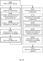
- Fig. 4A illustrates, in accordance with the exemplary aspects of the disclosure, a method for online firmware upgrade of a node 300a in a process control system 100, 100', wherein the node 300a comprises components, where each component is a separate executable running in a separate operating system process as provided by a real time operating system of the node 300a.
- the method is performed by a node manager 200a of the node 300a to be reconfigured.
- the method is advantageously provided as a computer program 1020.
- process block 104 starts in process block 104, by creating a new component for each of the at least one of the components to be upgraded such that each new component is implementing a part of the firmware upgrade corresponding to its component to be upgraded, and where each new component is a separate executable running in a separate operating system process, as further described below and in greater detail in conjunction with below figures.
- runtime data in each new component is synchronized with runtime data of its corresponding component to be upgraded, as further described below and in greater detail in conjunction with below figures.
- process block S112 the at least one component to be upgraded is replaced with its new component and thereby upgrading the node 300a, as further described below and in greater detail in conjunction with below figures.
- Fig. 4B is a flowchart illustrating further embodiments of methods for online firmware upgrade of a node 300 in a process control system 100, 100' shown in Fig. 4A .
- the node 300a comprises components. Each component is a separate executable running in a separate operating system process as provided by a real time operating system of the node 300a.
- the methods are performed by the node manager 200a.
- the methods are advantageously provided as computer programs 1020.
- Fig. 5 there are four use cases for the methods; 1) online firmware upgrade of a singular control service of the node 300, 2) online firmware upgrade of a singular platform component 320 of the node 300, 3) online firmware upgrade of all components of the node 300, and 4) online firmware upgrade of the complete firmware using redundant hardware.
- the use cases are illustrated in Fig. 5 , where use case 1 is illustrated at (a), use case 2 is illustrated at (b), use case 3 is illustrated at (c), and use case 4 is illustrated at (d), In Fig. 5 dotted lines are used to identify any component 200b, 310c, 310d, 330b, 340b to be upgraded, and where the redundant hardware is defined by node 300b.
- the formulation "firmware upgrade of at least one component” will be used when no differentiation needs to be made between these use cases.
- the firmware of a singular component 200b, 310c, 310d, 330b, 340b is upgraded. Upgrade of the firmware of a singular component requires that the new component (resulting from the firmware upgrade) is compatible with the remaining existing components in the node 300. If this is not the case, the third use case at (c) and (d) where the firmware of all components is upgraded.
- redundant hardware as defined by node 300b is used, which might be required for online upgrade of the firmware of the real time operating system and the node manager 200a.
- the firmware upgrade might be orchestrated from a firmware upgrade tool.
- the firmware upgrade tool might thus be used to transfer new firmware to the node 300a, and for sending upgrade commands during the upgrade process as defined by below process blocks S102-S112.
- the node manager 200a is thus the receiver of the upgrade commands and the new firmware and is configured to execute the upgrade commands by performing the method according to below process blocks S102-S112.
- the node manager 200a is configured to perform (optional) process block S102: S102:
- the node manager 200a obtains a firmware upgrade for at least one of the components of the node 300a.
- the node manager 200a uses the firmware upgrade to create new component executable(s) in parallel with the component executable(s) to be upgraded. That is, the node manager 200a is configured to perform process block S104: S104: The node manager 200a creates a new component for each of the at least one of the components to be upgraded such that each new component is implementing a part of the firmware upgrade corresponding to its component to be upgraded. Each new component is a separate executable running in a separate operating system process. Each operating system process might be provided by the real time operating system of the node 300a. The new component is created whilst the at least one of the components to be reconfigured is still running.
- the new component(s) are configured using the same configuration files as was used when configuring the old version.
- new configuration files are transferred with the new firmware. That is, according to an embodiment, each new component, when being created, is configured with same configuration as its corresponding component to be upgraded, and according to another embodiment, each new component, when being created, is configured with configuration as provided by the firmware upgrade.
- the node manager 200a might then stop the execution of all component(s) to be upgraded. That is, according to an embodiment the node manager 200a is configured to perform (optional) process block S106: S106: The node manager 200a stops execution of each component to be upgraded and running on the node 300a.
- the node manager 200a then starts the synchronization of runtime data in the new component(s) with runtime data from the old component(s). That is, the node manager 200a is configured to perform process block S108: S108: The node manager 200a synchronizes runtime data in each new component with runtime data of its corresponding component to be upgraded.
- Fig. 6(a) illustrates use cases 1 and 2
- Fig. 6(b) illustrates use cases 3 and 4.
- node 300a in Fig. 6(a) comprises the same components as node 300a of Fig. 5(a) and in addition explicitly shows the subcomponents 350a, 350b, 360a, 360b, 370a, 370b of control services 310a, 310b.
- Fig. 6(a) also shows subcomponents 350d, 360d, 370d corresponding to subcomponents of control service 310d in Fig. 5(a) .
- node 300a in Fig. 6(b) comprises the same components as node 300a of Fig.
- Fig. 5(d) shows the subcomponents 350a, 350b, 360a, 360b, 370a, 370b of control services 310a, 310b.
- Fig. 6(b) also shows the corresponding subcomponents 200a, 310c, 310d, 330b, 340b, 350c, 350d, 360c, 360d, 370c, 370d of node 300b in Fig. 5(d) .
- node manager API 360b subcomponent In uses cases 1 and 2 all control logic variables etc. that contains states that must be retained, are collected and submitted to the node manager API 360b subcomponent, which packages them into a container and forwards them to the node manager 200a, as symbolically illustrated by arrow 600a.
- the node manager 200a sends them to the node manager API 360c in the new component 310c, as symbolically illustrated by arrow 600b, where they are used for update of the runtime data.
- the collected states are submitted to the node manager 200, as symbolically illustrated by arrow 600c, which packages and forwards them, as symbolically illustrated by arrow 600d, to the new node manager 200b, which forwards them to the other new components, for update of the runtime data, as symbolically illustrated by arrow 600e.
- collection and update of states are only shown for one component; for control Service B.
- the transferred states have a version independent representation in the container to enable state transfer although the component internal state representations differ between the new and existing component versions.
- the node manager 200a After completed synchronization, the node manager 200a starts the new component(s), and deletes the old component(s). In use case 4, this is done through a switch over to the passive hardware unit (defined by node 300b), initiated by the node manager 200a. That is, the node manager 200a is configured to perform process block S112: S112: The node manager 200a replaces the at least one component to be upgraded with its new component and thereby upgrades the node 300a. In some aspects the node manager 200 upgrades the node 300a by starting execution of each new component upon having deleted the at least one component to be upgraded.
- Embodiments relating to further details of online firmware upgrade of a node 300a in a process control system 100, 100' as performed by the node manager 200a will now be disclosed.
- the node manager 200a is configured to perform (optional) process block S110: S110: The node manager 200a evaluates performance of each new component after synchronizing the runtime data but before deleting the at least one component to be upgraded.
- the evaluation is performed after the synchronization in process block S108.
- the node manager 200a is configured to perform (optional) process block S110a as part of process block S110: S110a: The node manager 200a starts parallel execution of each new component and the at least one component to be upgraded. Each new component and the at least one component to be upgraded are thus run in parallel. Each new component and the at least one component to be upgraded are run with same input, but only output produced by running the at least one component to be upgraded with the input is used in the process control system 100, 100'. That is, only the existing component controls the outputs.
- the firmware upgrade tool verifies that the new component has acceptable behavior, and thus performs as expected, by verifying that the new component produces expected output (for the given input). In other aspects verification is performed internally in the node.
- the node manager 200 is configured to perform (optional) process block Snob as part of process block S110: S110b: The node manager 200a verifies that each new component produces expected output.
- the node manager 200 is configured to perform (optional) process block S110c as part of process block S110: S110c: The node manager 200a, based on the verifying, stops execution of each new component and the at least one component to be upgraded. In other words, the execution is stopped upon the firmware upgrade tool, or the node manager 200a, having verified that each new component produces the same output as its corresponding component to be upgraded.
- each new component is, via the node manager 200a, provided with the input from its corresponding component to be upgraded.
- differences due to firmware upgrade of platform components cannot be evaluated. That is, according to an embodiment, the evaluating in processing block S110 is only performed when it is the firmware of the control service component that is to be upgraded. Hence, in view of the above, the evaluation might be performed for any of above use cases 1, 3 and 4.
- the new component can be set to active, i.e. being the component that e.g. controls the outputs of the node 300a and is accessed through the namespace of the new component. In use case 4, this is implemented through a switch, initiated by the node manager 200a, over to the hardware unit (defined by node 300b) running the new component.
- the node manager 200a and the node manager API 360a handle the synchronization of runtime data in the control services
- the node manager 200a and the node manager API 360a handle the synchronization of the component inputs as well as synchronization of the component execution.
- the new component subscribes to input signals and registers its output signals in the middleware (using the middleware API), thereby enabling a fast switch to the new component.
- the new component will not use the received signals during the evaluation and will not publish its signals to the middleware 330a, which during the evaluation are blocked by middleware API. Instead the new component will use input signals received from the existing component.
- the middleware API and the address space in the existing component forwards all received inputs to the node manager API, which packages them into a version independent container and submits them to the node manager 200a which forwards them to the node manager API in the new component, which makes them available to the middleware API.
- Fig. 7 illustrates synchronization of input data for use case 1 (at (a)) and case 4 (at (b)). The figure does not show all the details, e.g. that subscribed signals are received by both component versions (i.e., existing and new).
- Fig. 7(a) illustrates a node 300a having identical components as node 300a in Fig. 6(a) .
- Fig. 7(b) illustrates nodes 300a, 300b having identical components as nodes 300a, 300b in Fig. 6(b) .
- Input data from upper system parts are received as symbolically shown by arrow 700a by the communication interface 340a which forwards it to the address space 370b in the existing component as symbolically shown by arrow 700b.
- the address space 370b sends the input data to the node manager API 360b which forwards it to the new component as symbolically shown by arrows 700c, 700d.
- Other input data e.g. received by an I/O scanner in a component, is sent by the existing component to the new component using the node manager API 360.
- the new component is e.g. an I/O scanner, it will not control the I/O and devices during the evaluation. This is handled by the existing component.
- the executions of the component to be upgraded are synchronized, i.e. synchronization of input data as described above, copying signal values to internal variables, executing the control or scanner logic etc., and copying internal variable values to the signals.
- the middleware API 350 triggers the synchronization (e.g. copy-in, execute, copy-out, input data sync) using the node manager API 360, which forwards the synchronization information using the infrastructure as described above.
- Fig. 8(a) illustrates a node 300a having identical components as node 300a in Fig. 7(a) .
- Fig. 8(b) illustrates nodes 300a, 300b having identical components as nodes 300a, 300b in Fig. 7(b) .
- the new component in some aspects uses a separate namespace, an evaluation namespace, for its entities.
- a temporary namespace is used for each new component when evaluating the performance in process block S110.
- a specific control logic variable will have the same item ID in the existing component as in the new component, but different namespace IDs.
- the separate evaluation namespace is not needed in use case 4 since the existing component and the new component are running in different nodes 300a.
- the communication interface 340a, 340b subcomponent can be used to read control logic or I/O scanner variables values, signal values etc.
- the firmware upgrade tool might be configured to evaluate potential differences in runtime behavior and dynamics, by reading values from both namespaces, the ordinary namespace and the evaluation namespace.
- the firmware upgrade tool uses the namespace ID to identify which component (i.e., the existing component or the new component) to request for the value.
- the address space 370a-370e of the requested control service uses the item ID to find the corresponding entity.
- a control service has no knowledge about where its control service communication partners are allocated. Therefore, a control service that publishes a data set (a group of signals) can be replaced by another control service in the same node 300a or in a different node 300a without affecting the subscriber(s) of the data set, and a control service that subscribes to a data set can be replaced by another control service in the same node 300a or in a different node 300a without affecting the publisher of the data set.
- Fig. 9 schematically illustrates, in terms of a number of functional units, the components of a node manager 200a according to an embodiment.
- Processing circuitry 210 is provided using any combination of one or more of a suitable central processing unit (CPU), multiprocessor, microcontroller, digital signal processor (DSP), etc., capable of executing software instructions stored in a computer program product 1010 (as in Fig. 10 ), e.g. in the form of a storage medium 230.
- the processing circuitry 210 may further be provided as at least one application specific integrated circuit (ASIC), or field programmable gate array (FPGA).
- ASIC application specific integrated circuit
- FPGA field programmable gate array
- the processing circuitry 210 is configured to cause the node manager 200a to perform a set of operations, or process blocks, as disclosed above.
- the storage medium 230 may store the set of operations
- the processing circuitry 210 may be configured to retrieve the set of operations from the storage medium 230 to cause the node manager 200a to perform the set of operations.
- the set of operations may be provided as a set of executable instructions.
- the processing circuitry 210 is thereby arranged to execute methods as herein disclosed.
- the storage medium 230 may also comprise persistent storage, which, for example, can be any single one or combination of magnetic memory, optical memory, solid state memory or even remotely mounted memory.
- the node manager 200a may further comprise a communications interface 220 at least configured for communications with other components of the node. As such the communications interface 220 may comprise one or more transmitters and receivers, comprising analogue and digital components.
- the processing circuitry 210 controls the general operation of the node manager 200a e.g. by sending data and control signals to the communications interface 220 and the storage medium 230, by receiving data and reports from the communications interface 220, and by retrieving data and instructions from the storage medium 230.
- Other components, as well as the related functionality, of the node manager 200a are omitted in order not to obscure the concepts presented herein.
- the node manager 200a might be provided as a component of a node 300a and may hence share resources, such as processing circuitry 210, etc. with the node 300a as needed.
- Fig . 10 shows one example of a computer program product 1010 comprising computer readable storage medium 1030.
- a computer program 1020 can be stored, which computer program 1020 can cause the processing circuitry 210 and thereto operatively coupled entities and devices, such as the communications interface 220 and the storage medium 230, to execute methods according to embodiments described herein.
- the computer program 1020 and/or computer program product 1010 may thus provide means for performing any process blocks as herein disclosed.
- the computer program product 1010 is illustrated as an optical disc, such as a CD (compact disc) or a DVD (digital versatile disc) or a Blu-Ray disc.
- the computer program product 1010 could also be embodied as a memory, such as a random access memory (RAM), a read-only memory (ROM), an erasable programmable read-only memory (EPROM), or an electrically erasable programmable read-only memory (EEPROM) and more particularly as a non-volatile storage medium of a device in an external memory such as a USB (Universal Serial Bus) memory or a Flash memory, such as a compact Flash memory.
- the computer program 1020 is here schematically shown as a track on the depicted optical disk, the computer program 1020 can be stored in any way which is suitable for the computer program product 1010.
Landscapes
- Engineering & Computer Science (AREA)
- Theoretical Computer Science (AREA)
- General Engineering & Computer Science (AREA)
- Software Systems (AREA)
- Physics & Mathematics (AREA)
- General Physics & Mathematics (AREA)
- Computer Security & Cryptography (AREA)
- Databases & Information Systems (AREA)
- Computing Systems (AREA)
- Data Mining & Analysis (AREA)
- Stored Programmes (AREA)
Abstract

Description
- Embodiments presented herein relate to a method, a node manager, a computer program, and a computer program product for online firmware upgrade of a node in a process control system.
- Process control systems of today have a controller centric architecture, i.e. each controller executes a set of control logic applications using input/output (I/O) interfaces and devices connected to the controller, or via fieldbuses connected to the controller. I/O interfaces and devices are configured and scanned by the controller, which makes the controller dependent on knowledge about the hardware topology as well as I/O interface, device and fieldbus specific implementations. Access of I/O interfaces and device data from upper system levels is routed through the controller, and sometimes requires modifications of the control logic.
- Process control systems of today require redundant controller hardware, redundant gateway hardware, redundant device hardware etc., to support online firmware upgrade. This has a cost in terms of extra hardware, and sometimes also extra engineering.
- During an online firmware upgrade there might be a small unneglectable risk that the new firmware version has an unforeseen and undesirable impact on the control system runtime behaviour and dynamics, which in worst case can result in production losses.
- Hence, there is still a need for an improved firmware upgrade of process control systems.
- An object of embodiments herein is to provide efficient firmware upgrade of a process control system.
- According to a first aspect there is presented a method for online firmware upgrade of a node in a process control system. The node comprises components. Each component is a separate executable running in a separate operating system process as provided by a real time operating system of the node. The method is performed by a node manager of the node to be upgraded. The method comprises creating a new component for each of the at least one of the components to be upgraded such that each new component is implementing a part of the firmware upgrade corresponding to its component to be upgraded, and where each new component is a separate executable running in a separate operating system process. The method comprises synchronizing runtime data in each new component with runtime data of its corresponding component to be upgraded. The method comprises replacing the at least one component to be upgraded with its new component and thereby upgrading the node.
- According to a second aspect there is presented a node manager for online firmware upgrade of a node in a process control system. The node manager comprises processing circuitry. The processing circuitry is configured to cause the node manager to perform a method according to the first aspect.
- According to a third aspect there is presented a process control system comprising at least one node and node manager according to the second aspect.
- According to a fourth aspect there is presented a computer program for online firmware upgrade of a node in a process control system, the computer program comprising computer program code which, when run on a node manager, causes the node manager to perform a method according to the first aspect.
- According to a fifth aspect there is presented a computer program product comprising a computer program according to the fourth aspect and a computer readable storage medium on which the computer program is stored. The computer readable storage medium could be a non-transitory computer readable storage medium.
- Advantageously this provides efficient firmware upgrade of the node in the process control system.
- Advantageously this enables online upgrade of the firmware of a singular component or a set of components in non-redundant controllers, gateways, and devices as well as redundant controllers, gateways, and devices.
- Advantageously this can be combined with performance evaluation of the new components.
- Advantageously, such evaluation of the control system behavior can be used to avoid unforeseen, and undesirable, impacts on the control system runtime behavior and dynamics.
- Other objectives, features and advantages of the enclosed embodiments will be apparent from the following detailed disclosure, from the attached dependent claims as well as from the drawings.
- Generally, all terms used in the claims are to be interpreted according to their ordinary meaning in the technical field, unless explicitly defined otherwise herein. All references to "a/an/the element, apparatus, component, means, module, process block, etc." are to be interpreted openly as referring to at least one instance of the element, apparatus, component, means, module, process block, etc., unless explicitly stated otherwise. The process blocks of any method disclosed herein do not have to be performed in the exact order disclosed, unless explicitly stated.
- The inventive concept is now described, by way of example, with reference to the accompanying drawings, in which:
-
Fig. 1 schematically illustrates a network-centric architecture of a process control system; -
Fig. 2 schematically illustrates control services allocated to different nodes; -
Fig. 3 schematically illustrates a node architecture according to an embodiment; -
Figs. 4A and4B are flowcharts of methods according to embodiments; -
Fig. 5 schematically illustrates four uses cases for online firmware upgrade according to an embodiment; -
Fig. 6 schematically illustrates synchronization of runtime data according to an embodiment; -
Fig. 7 schematically illustrates synchronization of input data according to an embodiment; -
Fig. 8 schematically illustrates synchronization of execution according to an embodiment; -
Fig. 9 is a schematic diagram showing functional units of a node manager according to an embodiment; and -
Fig. 10 shows one example of a computer program product comprising computer readable storage medium according to an embodiment. - The inventive concept will now be described more fully hereinafter with reference to the accompanying drawings, in which certain embodiments of the inventive concept are shown. This inventive concept may, however, be embodied in many different forms and should not be construed as limited to the embodiments set forth herein; rather, these embodiments are provided by way of example so that this disclosure will be thorough and complete, and will fully convey the scope of the inventive concept to those skilled in the art. Like numbers refer to like elements throughout the description. Any process block or feature illustrated by dashed lines should be regarded as optional.
- In a network-centric architecture of the
process control system 100 as illustrated inFig. 1 , input/output (I/O) entities and devices, being examples ofnodes 300, are not "owned" by a controller, as in a controller-centric process control system architecture. The engineering tool for I/O entity and device configuration deploys configuration data to the I/O entities and devices without involving a (central) controller. Controllers are focused on execution of control logic and can access I/O signals from any I/O entity or device. The network-centric process control system architecture provides a system-wide easy access to I/O entity information and device information from upper system levels, such as Operations and Engineering, without any routing of information through the controller. The control logic does not have to be updated to access I/O entity information and device information. - In general terms, the exchange of process data between control services is handled by middleware. Data is then represented as signals. The control services represent the principal services in controllers, gateways and devices, e.g. execution of control logic in a controller, scanning of I/O and field devices in a fieldbus gateway, managing the device functionality in a device, etc.
- Control services are typically allocated in different nodes, with one or multiple control services per node.
- In general terms, a control service has no knowledge about where other control services that it interacts with are allocated. This is handled by the middleware and is transparent to the control service.
Fig. 2 shows an example of a process control system 100' with fourcontrol services node 300b being a device, anode 300c being a fieldbus gateway and anode 300a being a controller, where thenode 300a hosts twocontrol services node 300b hosts onecontrol service 310c, and where thenode 300c hosts onecontrol service 310d.Nodes middleware controller 330a in this example). - Interactions with controllers, devices etc. not using middleware, are handled by control services specific for the communication protocol needed for the interaction, as illustrated in
Fig. 2 . An Internet of Things (IoT) connect control service 310 operatively connects thecontroller 300a toIoT devices 110, and a fieldbus connect control service 310 of afieldbus gateway 300c operatively connects the fieldbus gateway to fieldbusdevices 120, e.g. Profibus devices. Such control services can execute in any node, e.g. in the controller node, as the IoT connect control service, or in a separate node, as the fieldbus connect control service. - Middleware and control services might be provided as separate executables, running in separate operating system processes, for memory protection and isolation of faults. A control service interacts with middleware through inter process communication.
- Control services are configured by a set of engineering tools; one tool for each control service type, e.g. one engineering tool for control logic configuration and another tool for I/O entity configuration and device configuration. This gives an isolation of e.g. control logic engineering from I/O engineering. That is, the control logic can be completely engineered without knowing where it will be executed, or how/where the I/O entities and devices are connected.
- Middleware is configured by a middleware configuration component, which uses signal definitions provided by the engineering tools to create the middleware configuration. The middleware configuration is sent with the control service configuration and forwarded to the middleware by the control services.
- In general terms, a signal defines a contract/interface between a publisher and a subscriber for the process data to be exchanged. A signal comprises the following attributes: system unique signal identity (ID), data type for the signal value, range and engineering unit for the signal value (for analog signals only), override value (used by the signal subscriber in case of bad quality), and substitute value (used by the signal publisher in case of bad quality). Signals are configured and connected to control logic variables and I/O channels, in the engineering tools for control logic and I/O engineering, and downloaded to the nodes. It is the responsibility of the middleware configuration component to guarantee that the signal IDs are unique within the system.
- Existing process control systems require redundant controller hardware, redundant gateway hardware, redundant device hardware, etc., to support online firmware upgrade. This has a cost in terms of extra hardware, and sometimes also extra engineering. Further, during an online firmware upgrade there could be a small unneglectable risk that the new firmware version has an unforeseen and undesirable impact on the control system runtime behavior and dynamics, which in worst case can result in production losses.
- The herein disclosed embodiments enable online firmware upgrade of a singular component, or a set of components, in non-redundant controllers, gateways and devices, as well as redundant controllers, gateways and devices. The control system behavior can be evaluated during a control service firmware upgrade to avoid unforeseen and undesirable impact on the control system runtime behavior and dynamics due to the online firmware upgrade. The online firmware upgrade can thus be supervised and evaluated before it is accepted or rejected.
-
Fig. 3 schematically illustrates the component architecture for anode 300a in theprocess control system 100, 100'. In some examples thenode 300a is a controller, a gateway, or a process device. - The
node 300a has one or multiplecontrol service components platform component 320a. Theplatform component 320a comprises the following components:middleware 330a, anode manager 200a, and acommunication interface 340a. In some examples thecommunication interface 340a comprises, or acts as, a vertical communication component. - Each component is a separate executable running in a separate operating system process provided by a real time operating system (not shown in the figure) of the
node 300a. In some examples the at least one component to be reconfigured is a control service component and/or aplatform component 320a on which the control service component is running. - Each component might comprise
middleware 330a for signal exchange that makes it possible for, for example, any control service to access any signal in any other control service without knowledge of network layout, control service deployment, or control service internals. - The
middleware 330a makes it possible to move a signal publisher from onenode 300a to another node without affecting the subscribers, and vice versa. - To simplify the control service implementation and to harmonize the control services behavior, each
control service component API address space platform component 320a. These subcomponents can also be copied to be part of the platform components. That is, in some examples the control service component comprises a middleware API, a node manager API, and an address space. - Each component has its own database for runtime and configuration data. That is, there is no separate component acting as a central database used by all components. The component runtime database is optimized for the most frequent data accesses, e.g. for control logic execution and allows control services to have a specific information model, e.g. IEC 61131-3 information model with program organization units (POUs), variables, etc. Information not needed by other components is hidden inside the control service. In this respect, the database might be provided as anything that is configured to store data such as a traditional database, a class, a table, or any other type of suitable data structure.
- The
node manager 200a is configured for the startup of all components in thenode 300, and for supervision of the runtime behavior, health, etc. for the components. Thenode manager 200a might be configured to, depending on its configuration, stop or restart execution of components. - The
node manager 200a is configured for performing the online firmware upgrade in thenode 300a. - As each component is a separate executable and as each component has its own database for runtime and configuration data, singular components as well as the complete set of components in a
node 300a can be upgraded without requiring a redundant hardware of thenode 300a. Hence, in some aspects the real time operating system runs on non-redundant hardware in thenode 300a. However, online upgrade of the real time operating system generally requires redundant hardware. That is, in other aspects the real time operating system runs on redundant hardware in thenode 300a. - The example embodiments disclosed herein in particular relate to mechanisms for online firmware upgrade of a
node 300a in aprocess control system 100, 100'. In order to obtain such mechanisms there is provided anode manager 200, a method performed by thenode manager 200a, a computer program product comprising code, for example in the form of a computer program, that when run on anode manager 200a, causes thenode manager 200a to perform the method. -
Fig. 4A illustrates, in accordance with the exemplary aspects of the disclosure, a method for online firmware upgrade of anode 300a in aprocess control system 100, 100', wherein thenode 300a comprises components, where each component is a separate executable running in a separate operating system process as provided by a real time operating system of thenode 300a. In an exemplary embodiment, the method is performed by anode manager 200a of thenode 300a to be reconfigured. The method is advantageously provided as acomputer program 1020. - The process starts in process block 104, by creating a new component for each of the at least one of the components to be upgraded such that each new component is implementing a part of the firmware upgrade corresponding to its component to be upgraded, and where each new component is a separate executable running in a separate operating system process, as further described below and in greater detail in conjunction with below figures.
- Next, in process block S108, runtime data in each new component is synchronized with runtime data of its corresponding component to be upgraded, as further described below and in greater detail in conjunction with below figures.
- Next, in process block S112, the at least one component to be upgraded is replaced with its new component and thereby upgrading the
node 300a, as further described below and in greater detail in conjunction with below figures. -
Fig. 4B is a flowchart illustrating further embodiments of methods for online firmware upgrade of anode 300 in aprocess control system 100, 100' shown inFig. 4A . Referring toFig. 4B , thenode 300a comprises components. Each component is a separate executable running in a separate operating system process as provided by a real time operating system of thenode 300a. In an exemplary embodiment, the methods are performed by thenode manager 200a. The methods are advantageously provided ascomputer programs 1020. - In general terms, there are four use cases for the methods; 1) online firmware upgrade of a singular control service of the
node 300, 2) online firmware upgrade of a singular platform component 320 of thenode 300, 3) online firmware upgrade of all components of thenode 300, and 4) online firmware upgrade of the complete firmware using redundant hardware. The use cases are illustrated inFig. 5 , whereuse case 1 is illustrated at (a), use case 2 is illustrated at (b),use case 3 is illustrated at (c), anduse case 4 is illustrated at (d), InFig. 5 dotted lines are used to identify anycomponent node 300b. The formulation "firmware upgrade of at least one component" will be used when no differentiation needs to be made between these use cases. In the first two use cases at (a) and (b), the firmware of asingular component node 300. If this is not the case, the third use case at (c) and (d) where the firmware of all components is upgraded. In the fourth use case (d) redundant hardware as defined bynode 300b is used, which might be required for online upgrade of the firmware of the real time operating system and thenode manager 200a. - The firmware upgrade might be orchestrated from a firmware upgrade tool. The firmware upgrade tool might thus be used to transfer new firmware to the
node 300a, and for sending upgrade commands during the upgrade process as defined by below process blocks S102-S112. Thenode manager 200a is thus the receiver of the upgrade commands and the new firmware and is configured to execute the upgrade commands by performing the method according to below process blocks S102-S112. Hence, according to an embodiment thenode manager 200a is configured to perform (optional) process block S102:
S102: Thenode manager 200a obtains a firmware upgrade for at least one of the components of thenode 300a. - The
node manager 200a uses the firmware upgrade to create new component executable(s) in parallel with the component executable(s) to be upgraded. That is, thenode manager 200a is configured to perform process block S104:
S104: Thenode manager 200a creates a new component for each of the at least one of the components to be upgraded such that each new component is implementing a part of the firmware upgrade corresponding to its component to be upgraded. Each new component is a separate executable running in a separate operating system process. Each operating system process might be provided by the real time operating system of thenode 300a. The new component is created whilst the at least one of the components to be reconfigured is still running. - The new component(s) are configured using the same configuration files as was used when configuring the old version. In case the old configuration file format is not compatible with the new firmware version, new configuration files are transferred with the new firmware. That is, according to an embodiment, each new component, when being created, is configured with same configuration as its corresponding component to be upgraded, and according to another embodiment, each new component, when being created, is configured with configuration as provided by the firmware upgrade.
- The
node manager 200a might then stop the execution of all component(s) to be upgraded. That is, according to an embodiment thenode manager 200a is configured to perform (optional) process block S106:
S106: Thenode manager 200a stops execution of each component to be upgraded and running on thenode 300a. - The
node manager 200a then starts the synchronization of runtime data in the new component(s) with runtime data from the old component(s). That is, thenode manager 200a is configured to perform process block S108:
S108: Thenode manager 200a synchronizes runtime data in each new component with runtime data of its corresponding component to be upgraded. - The synchronization is schematically illustrated in
Fig. 6 .Fig. 6(a) illustratesuse cases 1 and 2 andFig. 6(b) illustratesuse cases node 300a inFig. 6(a) comprises the same components asnode 300a ofFig. 5(a) and in addition explicitly shows the subcomponents 350a, 350b, 360a, 360b, 370a, 370b ofcontrol services Fig. 6(a) also showssubcomponents control service 310d inFig. 5(a) . Further,node 300a inFig. 6(b) comprises the same components asnode 300a ofFig. 5(d) and in addition explicitly shows the subcomponents 350a, 350b, 360a, 360b, 370a, 370b ofcontrol services Fig. 6(b) also shows the corresponding subcomponents 200a, 310c, 310d, 330b, 340b, 350c, 350d, 360c, 360d, 370c, 370d ofnode 300b inFig. 5(d) . - In uses
cases 1 and 2 all control logic variables etc. that contains states that must be retained, are collected and submitted to thenode manager API 360b subcomponent, which packages them into a container and forwards them to thenode manager 200a, as symbolically illustrated byarrow 600a. Thenode manager 200a sends them to thenode manager API 360c in thenew component 310c, as symbolically illustrated byarrow 600b, where they are used for update of the runtime data. - In
use cases node manager 200, as symbolically illustrated byarrow 600c, which packages and forwards them, as symbolically illustrated byarrow 600d, to thenew node manager 200b, which forwards them to the other new components, for update of the runtime data, as symbolically illustrated byarrow 600e. To simplify the figure, collection and update of states are only shown for one component; for control Service B. The transferred states have a version independent representation in the container to enable state transfer although the component internal state representations differ between the new and existing component versions. - After completed synchronization, the
node manager 200a starts the new component(s), and deletes the old component(s). Inuse case 4, this is done through a switch over to the passive hardware unit (defined bynode 300b), initiated by thenode manager 200a. That is, thenode manager 200a is configured to perform process block S112:
S112: Thenode manager 200a replaces the at least one component to be upgraded with its new component and thereby upgrades thenode 300a. In some aspects thenode manager 200 upgrades thenode 300a by starting execution of each new component upon having deleted the at least one component to be upgraded. - Embodiments relating to further details of online firmware upgrade of a
node 300a in aprocess control system 100, 100' as performed by thenode manager 200a will now be disclosed. - To avoid unforeseen and undesirable impact on the control system runtime behavior and dynamics due to the online firmware upgrade, in some aspects there is provided a mechanism for evaluation of the control system behavior during the firmware upgrade. In some aspects performance evaluation is performed by the firmware upgrade tool. In other aspects the performance evaluation is performed internally in the node. Hence, according to an embodiment, the
node manager 200a is configured to perform (optional) process block S110:
S110: Thenode manager 200a evaluates performance of each new component after synchronizing the runtime data but before deleting the at least one component to be upgraded. - The evaluation is performed after the synchronization in process block S108.
- Both the new component and the existing component to be upgraded are started and run in parallel. Hence, according to an embodiment, the
node manager 200a is configured to perform (optional) process block S110a as part of process block S110:
S110a: Thenode manager 200a starts parallel execution of each new component and the at least one component to be upgraded. Each new component and the at least one component to be upgraded are thus run in parallel. Each new component and the at least one component to be upgraded are run with same input, but only output produced by running the at least one component to be upgraded with the input is used in theprocess control system 100, 100'. That is, only the existing component controls the outputs. - Potential differences in runtime behavior and dynamics for one or multiple components can thereby be evaluated. In some aspects the firmware upgrade tool verifies that the new component has acceptable behavior, and thus performs as expected, by verifying that the new component produces expected output (for the given input). In other aspects verification is performed internally in the node. In particular, according to an embodiment, the
node manager 200 is configured to perform (optional) process block Snob as part of process block S110:
S110b: Thenode manager 200a verifies that each new component produces expected output. - Once this has been verified the execution is stopped. In particular, according to an embodiment, the
node manager 200 is configured to perform (optional) process block S110c as part of process block S110:
S110c: Thenode manager 200a, based on the verifying, stops execution of each new component and the at least one component to be upgraded. In other words, the execution is stopped upon the firmware upgrade tool, or thenode manager 200a, having verified that each new component produces the same output as its corresponding component to be upgraded. - In case the firmware upgrade tool, or the
node manager 200a, cannot verify that each new component produces the expected output the online firmware upgrade process is aborted. In case of abortion each new component is deleted and operation of thenode 300a is continued using the corresponding component(s) that was/were to be upgraded. - As will be further disclosed below, according to an embodiment, each new component is, via the
node manager 200a, provided with the input from its corresponding component to be upgraded. - In some aspects, differences due to firmware upgrade of platform components cannot be evaluated. That is, according to an embodiment, the evaluating in processing block S110 is only performed when it is the firmware of the control service component that is to be upgraded. Hence, in view of the above, the evaluation might be performed for any of
above use cases - Once it has been verified that the new firmware version, as resulting from the firmware upgrade, operates as expected, the new component can be set to active, i.e. being the component that e.g. controls the outputs of the
node 300a and is accessed through the namespace of the new component. Inuse case 4, this is implemented through a switch, initiated by thenode manager 200a, over to the hardware unit (defined bynode 300b) running the new component. - In a similar way as the
node manager 200a and thenode manager API 360a handle the synchronization of runtime data in the control services, thenode manager 200a and thenode manager API 360a handle the synchronization of the component inputs as well as synchronization of the component execution. - In the startup of the new component, the new component subscribes to input signals and registers its output signals in the middleware (using the middleware API), thereby enabling a fast switch to the new component. However, the new component will not use the received signals during the evaluation and will not publish its signals to the
middleware 330a, which during the evaluation are blocked by middleware API. Instead the new component will use input signals received from the existing component. The middleware API and the address space in the existing component forwards all received inputs to the node manager API, which packages them into a version independent container and submits them to thenode manager 200a which forwards them to the node manager API in the new component, which makes them available to the middleware API. -
Fig. 7 illustrates synchronization of input data for use case 1 (at (a)) and case 4 (at (b)). The figure does not show all the details, e.g. that subscribed signals are received by both component versions (i.e., existing and new).Fig. 7(a) illustrates anode 300a having identical components asnode 300a inFig. 6(a) .Fig. 7(b) illustratesnodes nodes Fig. 6(b) . - Other types of input data e.g. from communication with upper system parts, from an I/O scanner or from a communication stack are also synchronized. Input data from upper system parts are received as symbolically shown by
arrow 700a by thecommunication interface 340a which forwards it to theaddress space 370b in the existing component as symbolically shown byarrow 700b. Theaddress space 370b sends the input data to thenode manager API 360b which forwards it to the new component as symbolically shown byarrows - The executions of the component to be upgraded are synchronized, i.e. synchronization of input data as described above, copying signal values to internal variables, executing the control or scanner logic etc., and copying internal variable values to the signals. In this respect, the middleware API 350 triggers the synchronization (e.g. copy-in, execute, copy-out, input data sync) using the node manager API 360, which forwards the synchronization information using the infrastructure as described above. This is illustrated by
arrows Fig. 8 for use case 1 (at (a)) and case 3 (at (b)).Fig. 8(a) illustrates anode 300a having identical components asnode 300a inFig. 7(a) .Fig. 8(b) illustratesnodes nodes Fig. 7(b) . - As the existing component and the new component expose the same entities in address space, the new component in some aspects uses a separate namespace, an evaluation namespace, for its entities. Hence, according to an embodiment, a temporary namespace is used for each new component when evaluating the performance in process block S110. For example, a specific control logic variable will have the same item ID in the existing component as in the new component, but different namespace IDs. However, the separate evaluation namespace is not needed in
use case 4 since the existing component and the new component are running indifferent nodes 300a. - The
communication interface address space 370a-370e of the requested control service uses the item ID to find the corresponding entity. - A control service has no knowledge about where its control service communication partners are allocated. Therefore, a control service that publishes a data set (a group of signals) can be replaced by another control service in the
same node 300a or in adifferent node 300a without affecting the subscriber(s) of the data set, and a control service that subscribes to a data set can be replaced by another control service in thesame node 300a or in adifferent node 300a without affecting the publisher of the data set. -
Fig. 9 schematically illustrates, in terms of a number of functional units, the components of anode manager 200a according to an embodiment.Processing circuitry 210 is provided using any combination of one or more of a suitable central processing unit (CPU), multiprocessor, microcontroller, digital signal processor (DSP), etc., capable of executing software instructions stored in a computer program product 1010 (as inFig. 10 ), e.g. in the form of astorage medium 230. Theprocessing circuitry 210 may further be provided as at least one application specific integrated circuit (ASIC), or field programmable gate array (FPGA). - Particularly, the
processing circuitry 210 is configured to cause thenode manager 200a to perform a set of operations, or process blocks, as disclosed above. For example, thestorage medium 230 may store the set of operations, and theprocessing circuitry 210 may be configured to retrieve the set of operations from thestorage medium 230 to cause thenode manager 200a to perform the set of operations. The set of operations may be provided as a set of executable instructions. - Thus the
processing circuitry 210 is thereby arranged to execute methods as herein disclosed. Thestorage medium 230 may also comprise persistent storage, which, for example, can be any single one or combination of magnetic memory, optical memory, solid state memory or even remotely mounted memory. Thenode manager 200a may further comprise acommunications interface 220 at least configured for communications with other components of the node. As such thecommunications interface 220 may comprise one or more transmitters and receivers, comprising analogue and digital components. Theprocessing circuitry 210 controls the general operation of thenode manager 200a e.g. by sending data and control signals to thecommunications interface 220 and thestorage medium 230, by receiving data and reports from thecommunications interface 220, and by retrieving data and instructions from thestorage medium 230. Other components, as well as the related functionality, of thenode manager 200a are omitted in order not to obscure the concepts presented herein. - As disclosed above, the
node manager 200a might be provided as a component of anode 300a and may hence share resources, such asprocessing circuitry 210, etc. with thenode 300a as needed. -
Fig. 10 shows one example of acomputer program product 1010 comprising computerreadable storage medium 1030. On this computerreadable storage medium 1030, acomputer program 1020 can be stored, whichcomputer program 1020 can cause theprocessing circuitry 210 and thereto operatively coupled entities and devices, such as thecommunications interface 220 and thestorage medium 230, to execute methods according to embodiments described herein. Thecomputer program 1020 and/orcomputer program product 1010 may thus provide means for performing any process blocks as herein disclosed. - In the example of
Fig. 10 , thecomputer program product 1010 is illustrated as an optical disc, such as a CD (compact disc) or a DVD (digital versatile disc) or a Blu-Ray disc. Thecomputer program product 1010 could also be embodied as a memory, such as a random access memory (RAM), a read-only memory (ROM), an erasable programmable read-only memory (EPROM), or an electrically erasable programmable read-only memory (EEPROM) and more particularly as a non-volatile storage medium of a device in an external memory such as a USB (Universal Serial Bus) memory or a Flash memory, such as a compact Flash memory. Thus, while thecomputer program 1020 is here schematically shown as a track on the depicted optical disk, thecomputer program 1020 can be stored in any way which is suitable for thecomputer program product 1010. - The inventive concept has mainly been described above with reference to a few embodiments. However, as is readily appreciated by a person skilled in the art, other embodiments than the ones disclosed above are equally possible within the scope of the inventive concept, as defined by the appended patent claims.
Claims (15)
- A method for online firmware upgrade of a node (300a) in a process control system (100,100'), wherein the node (300a) comprises components, where each component is a separate executable running in a separate operating system process as provided by a real time operating system of the node (300a), the method being performed by a node manager (200a) of the node (300a) to be upgraded, the method comprising:creating (S104) a new component for each of the at least one of the components to be upgraded such that each new component is implementing a part of the firmware upgrade corresponding to its component to be upgraded, and where each new component is a separate executable running in a separate operating system process;synchronizing (S108) runtime data in each new component with runtime data of its corresponding component to be upgraded; andreplacing (S112) the at least one component to be upgraded with its new component and thereby upgrading the node (300a).
- The method according to claim 1, wherein each new component, when being created, is configured with same configuration as its corresponding component to be upgraded.
- The method according to claim 1, wherein each new component, when being created, is configured with configuration as provided by the firmware upgrade.
- The method according to claim 1, wherein the real time operating system runs on non-redundant hardware in the node (300a).
- The method according to claim 1, further comprising:
evaluating (S110) performance of each new component after synchronizing the runtime data but before deleting the at least one component to be upgraded. - The method according to claim 5, wherein evaluating the performance comprises:starting (S11a) parallel execution of each new component and the at least one component to be upgraded, wherein each new component and the at least one component to be upgraded are run with same input, but wherein only output produced by running the at least one component to be upgraded with the input is used in the process control system (100, 100');verifying (S104b) that each new component produces expected output; andstopping (S110C), based on the verifying, execution of each new component and the at least one component to be upgraded.
- The method according to claim 6, wherein each new component is, via the node manager (200a), provided with the input from its corresponding component to be upgraded.
- The method according to any of claims 5, 6, or 7, wherein a temporary namespace is used for each new component when evaluating the performance.
- The method according to claim 1, wherein the at least one component to be upgraded is a control service component (310a) and/or a platform component (340a) on which the control service component (310a) is running.
- The method according to claim 9, wherein the control service component (310a) comprises a middleware API (350a), a node manager API (360a), and an address space (370a).
- The method according to claim 9, wherein the platform component (320) comprises middleware (330a), the node manager (200a), and a communication interface (340a).
- The method according to any of claims 5 or 6 in combination with any of claims 9, 10, or 11, wherein the evaluating is only performed when it is the firmware of the control service component (310a) that is to be upgraded.
- The method according to claim 1, further comprising:
stopping (S106) execution of each component to be upgraded and running on the node (300a) after having created the new component and before synchronizing the runtime data. - A node manager (200a) for online firmware upgrade of a node (300a) in a process control system (100, 100'), wherein the node (300a) comprises components, where each component is a separate executable running in a separate operating system process as provided by a real time operating system of the node (300a), the node manager (200a) comprising processing circuitry (210), the processing circuitry (210a) being configured to cause the node manager (200a) to perform a method according to any of the preceding claims.
- A computer program (1020) for online firmware upgrade of a node (300a) in a process control system (100, 100'), wherein the node (300a) comprises components, where each component is a separate executable running in a separate operating system process as provided by a real time operating system of the node (300a), the computer program comprising computer code which, when run on processing circuitry (210) of a node manager (200a), causes the node manager (200a) to perform a method according to any of the preceding claims
Priority Applications (3)
| Application Number | Priority Date | Filing Date | Title |
|---|---|---|---|
| EP19160284.6A EP3702910B1 (en) | 2019-03-01 | 2019-03-01 | Online firmware upgrade of a node in a process control system |
| US16/800,362 US11281448B2 (en) | 2019-03-01 | 2020-02-25 | Online firmware upgrade of a node in a process control system |
| CN202010130758.2A CN111638890B (en) | 2019-03-01 | 2020-02-28 | Method, node manager and computer program product for online firmware upgrade of nodes in a process control system |
Applications Claiming Priority (1)
| Application Number | Priority Date | Filing Date | Title |
|---|---|---|---|
| EP19160284.6A EP3702910B1 (en) | 2019-03-01 | 2019-03-01 | Online firmware upgrade of a node in a process control system |
Publications (2)
| Publication Number | Publication Date |
|---|---|
| EP3702910A1 true EP3702910A1 (en) | 2020-09-02 |
| EP3702910B1 EP3702910B1 (en) | 2022-06-29 |
Family
ID=65724162
Family Applications (1)
| Application Number | Title | Priority Date | Filing Date |
|---|---|---|---|
| EP19160284.6A Active EP3702910B1 (en) | 2019-03-01 | 2019-03-01 | Online firmware upgrade of a node in a process control system |
Country Status (3)
| Country | Link |
|---|---|
| US (1) | US11281448B2 (en) |
| EP (1) | EP3702910B1 (en) |
| CN (1) | CN111638890B (en) |
Families Citing this family (3)
| Publication number | Priority date | Publication date | Assignee | Title |
|---|---|---|---|---|
| EP4063974B1 (en) * | 2021-03-23 | 2025-10-22 | ABB Schweiz AG | Controlling an industrial process using virtualized instances of control software |
| EP4372550A1 (en) * | 2022-11-17 | 2024-05-22 | VEGA Grieshaber KG | Method for reducing interruption times during a software update of a field device |
| EP4506811A1 (en) * | 2023-08-11 | 2025-02-12 | Siemens Aktiengesellschaft | Method for updating a software version for a control device |
Citations (1)
| Publication number | Priority date | Publication date | Assignee | Title |
|---|---|---|---|---|
| US10114665B2 (en) * | 2015-11-18 | 2018-10-30 | Level 3 Communications, Llc | Communication node upgrade system and method for a communication network |
Family Cites Families (11)
| Publication number | Priority date | Publication date | Assignee | Title |
|---|---|---|---|---|
| EP1890230A1 (en) * | 2006-08-15 | 2008-02-20 | Alcatel Lucent | Software replacement in a stream processing system |
| US20090076628A1 (en) * | 2007-09-18 | 2009-03-19 | David Mark Smith | Methods and apparatus to upgrade and provide control redundancy in process plants |
| US8856776B2 (en) * | 2009-02-05 | 2014-10-07 | International Business Machines Corporation | Updating firmware without disrupting service |
| US9639347B2 (en) * | 2009-12-21 | 2017-05-02 | International Business Machines Corporation | Updating a firmware package |
| US20140304696A1 (en) * | 2011-10-11 | 2014-10-09 | Sandvik Mining And Construction Oy | Arrangement for updating a control system |
| US9256412B2 (en) * | 2012-07-04 | 2016-02-09 | Sap Se | Scheduled and quarantined software deployment based on dependency analysis |
| CN104572229B (en) * | 2015-02-12 | 2018-07-20 | 西安诺瓦电子科技有限公司 | The firmware upgrade method and device for upgrading firmware of embedded system |
| JP6675271B2 (en) * | 2015-09-14 | 2020-04-01 | パナソニック インテレクチュアル プロパティ コーポレーション オブ アメリカPanasonic Intellectual Property Corporation of America | Gateway device, in-vehicle network system, and firmware update method |
| US9880829B2 (en) * | 2015-12-14 | 2018-01-30 | Telefonaktiebolaget Lm Ericsson (Publ) | Method and apparatus for performing hitless update of line cards of a network device |
| CN107515776B (en) * | 2017-07-18 | 2021-04-09 | 深信服科技股份有限公司 | Method for upgrading service continuously, node to be upgraded and readable storage medium |
| US10642603B2 (en) * | 2018-01-16 | 2020-05-05 | Nutanix, Inc. | Scheduling upgrades in distributed computing systems |
-
2019
- 2019-03-01 EP EP19160284.6A patent/EP3702910B1/en active Active
-
2020
- 2020-02-25 US US16/800,362 patent/US11281448B2/en active Active
- 2020-02-28 CN CN202010130758.2A patent/CN111638890B/en active Active
Patent Citations (1)
| Publication number | Priority date | Publication date | Assignee | Title |
|---|---|---|---|---|
| US10114665B2 (en) * | 2015-11-18 | 2018-10-30 | Level 3 Communications, Llc | Communication node upgrade system and method for a communication network |
Also Published As
| Publication number | Publication date |
|---|---|
| CN111638890A (en) | 2020-09-08 |
| CN111638890B (en) | 2024-09-17 |
| US20200278856A1 (en) | 2020-09-03 |
| EP3702910B1 (en) | 2022-06-29 |
| US11281448B2 (en) | 2022-03-22 |
Similar Documents
| Publication | Publication Date | Title |
|---|---|---|
| US11575769B2 (en) | Redundancy in a network centric process control system | |
| US11281448B2 (en) | Online firmware upgrade of a node in a process control system | |
| CN112583630B (en) | Device management method, device, system, device and storage medium | |
| US11544076B2 (en) | Online reconfiguration of a node in a process control system | |
| CN101727475B (en) | Method, device and system for acquiring database access process | |
| US11500690B2 (en) | Dynamic load balancing in network centric process control systems | |
| US11693643B2 (en) | Network-based solution module deployment platform | |
| US20160378434A1 (en) | Integration of revision control systems and process tools | |
| US20120324436A1 (en) | Method of updating versioned software using a shared cache | |
| CN112241280B (en) | Firmware updates for modular node components | |
| WO2021136233A1 (en) | Service upgrading method, device and system | |
| CN113867778A (en) | A method, device, electronic device and storage medium for generating an image file | |
| CN119512568A (en) | A convenient deployment method for multiple optional components based on DevOps | |
| CN111741102A (en) | Upgrading method and device for distributed micro-service application | |
| WO2020036094A1 (en) | Support device, support program, and control system | |
| US20150282121A1 (en) | Local resource sharing method of machine to machine component and apparatus thereof | |
| EP3702920A1 (en) | Heterogeneous execution engines in a network centric process control system | |
| JP7814618B1 (en) | Function expansion device, function expansion system, edge device, function expansion method, and function expansion program | |
| CN120762734B (en) | Application release control method, system and server | |
| JP2001177549A (en) | System for changing inter-device communication parameter in transmission network system | |
| KR102039593B1 (en) | Apparatus and method for managing service | |
| CN121309337A (en) | Configuration methods, devices, electronic equipment, and storage media for C2F application gateways | |
| CN119690531A (en) | A code dynamic loading execution method, executor and system | |
| CN121098895A (en) | Service start-stop control method, device, equipment and storage medium | |
| CN116841690A (en) | Application deployment method, device, electronic equipment and storage medium |
Legal Events
| Date | Code | Title | Description |
|---|---|---|---|
| PUAI | Public reference made under article 153(3) epc to a published international application that has entered the european phase |
Free format text: ORIGINAL CODE: 0009012 |
|
| STAA | Information on the status of an ep patent application or granted ep patent |
Free format text: STATUS: THE APPLICATION HAS BEEN PUBLISHED |
|
| AK | Designated contracting states |
Kind code of ref document: A1 Designated state(s): AL AT BE BG CH CY CZ DE DK EE ES FI FR GB GR HR HU IE IS IT LI LT LU LV MC MK MT NL NO PL PT RO RS SE SI SK SM TR |
|
| AX | Request for extension of the european patent |
Extension state: BA ME |
|
| STAA | Information on the status of an ep patent application or granted ep patent |
Free format text: STATUS: REQUEST FOR EXAMINATION WAS MADE |
|
| 17P | Request for examination filed |
Effective date: 20210301 |
|
| RBV | Designated contracting states (corrected) |
Designated state(s): AL AT BE BG CH CY CZ DE DK EE ES FI FR GB GR HR HU IE IS IT LI LT LU LV MC MK MT NL NO PL PT RO RS SE SI SK SM TR |
|
| STAA | Information on the status of an ep patent application or granted ep patent |
Free format text: STATUS: EXAMINATION IS IN PROGRESS |
|
| 17Q | First examination report despatched |
Effective date: 20210804 |
|
| GRAP | Despatch of communication of intention to grant a patent |
Free format text: ORIGINAL CODE: EPIDOSNIGR1 |
|
| STAA | Information on the status of an ep patent application or granted ep patent |
Free format text: STATUS: GRANT OF PATENT IS INTENDED |
|
| INTG | Intention to grant announced |
Effective date: 20220215 |
|
| GRAS | Grant fee paid |
Free format text: ORIGINAL CODE: EPIDOSNIGR3 |
|
| GRAA | (expected) grant |
Free format text: ORIGINAL CODE: 0009210 |
|
| STAA | Information on the status of an ep patent application or granted ep patent |
Free format text: STATUS: THE PATENT HAS BEEN GRANTED |
|
| AK | Designated contracting states |
Kind code of ref document: B1 Designated state(s): AL AT BE BG CH CY CZ DE DK EE ES FI FR GB GR HR HU IE IS IT LI LT LU LV MC MK MT NL NO PL PT RO RS SE SI SK SM TR |
|
| RAP3 | Party data changed (applicant data changed or rights of an application transferred) |
Owner name: ABB SCHWEIZ AG |
|
| REG | Reference to a national code |
Ref country code: CH Ref legal event code: EP |
|
| REG | Reference to a national code |
Ref country code: AT Ref legal event code: REF Ref document number: 1501787 Country of ref document: AT Kind code of ref document: T Effective date: 20220715 |
|
| REG | Reference to a national code |
Ref country code: IE Ref legal event code: FG4D |
|
| REG | Reference to a national code |
Ref country code: DE Ref legal event code: R096 Ref document number: 602019016300 Country of ref document: DE |
|
| REG | Reference to a national code |
Ref country code: LT Ref legal event code: MG9D |
|
| PG25 | Lapsed in a contracting state [announced via postgrant information from national office to epo] |
Ref country code: SE Free format text: LAPSE BECAUSE OF FAILURE TO SUBMIT A TRANSLATION OF THE DESCRIPTION OR TO PAY THE FEE WITHIN THE PRESCRIBED TIME-LIMIT Effective date: 20220629 Ref country code: NO Free format text: LAPSE BECAUSE OF FAILURE TO SUBMIT A TRANSLATION OF THE DESCRIPTION OR TO PAY THE FEE WITHIN THE PRESCRIBED TIME-LIMIT Effective date: 20220929 Ref country code: LT Free format text: LAPSE BECAUSE OF FAILURE TO SUBMIT A TRANSLATION OF THE DESCRIPTION OR TO PAY THE FEE WITHIN THE PRESCRIBED TIME-LIMIT Effective date: 20220629 Ref country code: HR Free format text: LAPSE BECAUSE OF FAILURE TO SUBMIT A TRANSLATION OF THE DESCRIPTION OR TO PAY THE FEE WITHIN THE PRESCRIBED TIME-LIMIT Effective date: 20220629 Ref country code: GR Free format text: LAPSE BECAUSE OF FAILURE TO SUBMIT A TRANSLATION OF THE DESCRIPTION OR TO PAY THE FEE WITHIN THE PRESCRIBED TIME-LIMIT Effective date: 20220930 Ref country code: FI Free format text: LAPSE BECAUSE OF FAILURE TO SUBMIT A TRANSLATION OF THE DESCRIPTION OR TO PAY THE FEE WITHIN THE PRESCRIBED TIME-LIMIT Effective date: 20220629 Ref country code: BG Free format text: LAPSE BECAUSE OF FAILURE TO SUBMIT A TRANSLATION OF THE DESCRIPTION OR TO PAY THE FEE WITHIN THE PRESCRIBED TIME-LIMIT Effective date: 20220929 |
|
| REG | Reference to a national code |
Ref country code: NL Ref legal event code: MP Effective date: 20220629 |
|
| REG | Reference to a national code |
Ref country code: AT Ref legal event code: MK05 Ref document number: 1501787 Country of ref document: AT Kind code of ref document: T Effective date: 20220629 |
|
| PG25 | Lapsed in a contracting state [announced via postgrant information from national office to epo] |
Ref country code: RS Free format text: LAPSE BECAUSE OF FAILURE TO SUBMIT A TRANSLATION OF THE DESCRIPTION OR TO PAY THE FEE WITHIN THE PRESCRIBED TIME-LIMIT Effective date: 20220629 Ref country code: LV Free format text: LAPSE BECAUSE OF FAILURE TO SUBMIT A TRANSLATION OF THE DESCRIPTION OR TO PAY THE FEE WITHIN THE PRESCRIBED TIME-LIMIT Effective date: 20220629 |
|
| PG25 | Lapsed in a contracting state [announced via postgrant information from national office to epo] |
Ref country code: NL Free format text: LAPSE BECAUSE OF FAILURE TO SUBMIT A TRANSLATION OF THE DESCRIPTION OR TO PAY THE FEE WITHIN THE PRESCRIBED TIME-LIMIT Effective date: 20220629 |
|
| PG25 | Lapsed in a contracting state [announced via postgrant information from national office to epo] |
Ref country code: SM Free format text: LAPSE BECAUSE OF FAILURE TO SUBMIT A TRANSLATION OF THE DESCRIPTION OR TO PAY THE FEE WITHIN THE PRESCRIBED TIME-LIMIT Effective date: 20220629 Ref country code: SK Free format text: LAPSE BECAUSE OF FAILURE TO SUBMIT A TRANSLATION OF THE DESCRIPTION OR TO PAY THE FEE WITHIN THE PRESCRIBED TIME-LIMIT Effective date: 20220629 Ref country code: RO Free format text: LAPSE BECAUSE OF FAILURE TO SUBMIT A TRANSLATION OF THE DESCRIPTION OR TO PAY THE FEE WITHIN THE PRESCRIBED TIME-LIMIT Effective date: 20220629 Ref country code: PT Free format text: LAPSE BECAUSE OF FAILURE TO SUBMIT A TRANSLATION OF THE DESCRIPTION OR TO PAY THE FEE WITHIN THE PRESCRIBED TIME-LIMIT Effective date: 20221031 Ref country code: ES Free format text: LAPSE BECAUSE OF FAILURE TO SUBMIT A TRANSLATION OF THE DESCRIPTION OR TO PAY THE FEE WITHIN THE PRESCRIBED TIME-LIMIT Effective date: 20220629 Ref country code: EE Free format text: LAPSE BECAUSE OF FAILURE TO SUBMIT A TRANSLATION OF THE DESCRIPTION OR TO PAY THE FEE WITHIN THE PRESCRIBED TIME-LIMIT Effective date: 20220629 Ref country code: AT Free format text: LAPSE BECAUSE OF FAILURE TO SUBMIT A TRANSLATION OF THE DESCRIPTION OR TO PAY THE FEE WITHIN THE PRESCRIBED TIME-LIMIT Effective date: 20220629 |
|
| PG25 | Lapsed in a contracting state [announced via postgrant information from national office to epo] |
Ref country code: PL Free format text: LAPSE BECAUSE OF FAILURE TO SUBMIT A TRANSLATION OF THE DESCRIPTION OR TO PAY THE FEE WITHIN THE PRESCRIBED TIME-LIMIT Effective date: 20220629 Ref country code: IS Free format text: LAPSE BECAUSE OF FAILURE TO SUBMIT A TRANSLATION OF THE DESCRIPTION OR TO PAY THE FEE WITHIN THE PRESCRIBED TIME-LIMIT Effective date: 20221029 |
|
| REG | Reference to a national code |
Ref country code: DE Ref legal event code: R097 Ref document number: 602019016300 Country of ref document: DE |
|
| PG25 | Lapsed in a contracting state [announced via postgrant information from national office to epo] |
Ref country code: AL Free format text: LAPSE BECAUSE OF FAILURE TO SUBMIT A TRANSLATION OF THE DESCRIPTION OR TO PAY THE FEE WITHIN THE PRESCRIBED TIME-LIMIT Effective date: 20220629 |
|
| PG25 | Lapsed in a contracting state [announced via postgrant information from national office to epo] |
Ref country code: DK Free format text: LAPSE BECAUSE OF FAILURE TO SUBMIT A TRANSLATION OF THE DESCRIPTION OR TO PAY THE FEE WITHIN THE PRESCRIBED TIME-LIMIT Effective date: 20220629 Ref country code: CZ Free format text: LAPSE BECAUSE OF FAILURE TO SUBMIT A TRANSLATION OF THE DESCRIPTION OR TO PAY THE FEE WITHIN THE PRESCRIBED TIME-LIMIT Effective date: 20220629 |
|
| PLBE | No opposition filed within time limit |
Free format text: ORIGINAL CODE: 0009261 |
|
| STAA | Information on the status of an ep patent application or granted ep patent |
Free format text: STATUS: NO OPPOSITION FILED WITHIN TIME LIMIT |
|
| 26N | No opposition filed |
Effective date: 20230330 |
|
| PG25 | Lapsed in a contracting state [announced via postgrant information from national office to epo] |
Ref country code: SI Free format text: LAPSE BECAUSE OF FAILURE TO SUBMIT A TRANSLATION OF THE DESCRIPTION OR TO PAY THE FEE WITHIN THE PRESCRIBED TIME-LIMIT Effective date: 20220629 |
|
| PG25 | Lapsed in a contracting state [announced via postgrant information from national office to epo] |
Ref country code: MC Free format text: LAPSE BECAUSE OF FAILURE TO SUBMIT A TRANSLATION OF THE DESCRIPTION OR TO PAY THE FEE WITHIN THE PRESCRIBED TIME-LIMIT Effective date: 20220629 |
|
| REG | Reference to a national code |
Ref country code: CH Ref legal event code: PL |
|
| REG | Reference to a national code |
Ref country code: BE Ref legal event code: MM Effective date: 20230331 |
|
| PG25 | Lapsed in a contracting state [announced via postgrant information from national office to epo] |
Ref country code: LU Free format text: LAPSE BECAUSE OF NON-PAYMENT OF DUE FEES Effective date: 20230301 |
|
| REG | Reference to a national code |
Ref country code: IE Ref legal event code: MM4A |
|
| PG25 | Lapsed in a contracting state [announced via postgrant information from national office to epo] |
Ref country code: LI Free format text: LAPSE BECAUSE OF NON-PAYMENT OF DUE FEES Effective date: 20230331 Ref country code: IT Free format text: LAPSE BECAUSE OF FAILURE TO SUBMIT A TRANSLATION OF THE DESCRIPTION OR TO PAY THE FEE WITHIN THE PRESCRIBED TIME-LIMIT Effective date: 20220629 Ref country code: IE Free format text: LAPSE BECAUSE OF NON-PAYMENT OF DUE FEES Effective date: 20230301 Ref country code: FR Free format text: LAPSE BECAUSE OF NON-PAYMENT OF DUE FEES Effective date: 20230331 Ref country code: CH Free format text: LAPSE BECAUSE OF NON-PAYMENT OF DUE FEES Effective date: 20230331 |
|
| PG25 | Lapsed in a contracting state [announced via postgrant information from national office to epo] |
Ref country code: BE Free format text: LAPSE BECAUSE OF NON-PAYMENT OF DUE FEES Effective date: 20230331 |
|
| PG25 | Lapsed in a contracting state [announced via postgrant information from national office to epo] |
Ref country code: BG Free format text: LAPSE BECAUSE OF FAILURE TO SUBMIT A TRANSLATION OF THE DESCRIPTION OR TO PAY THE FEE WITHIN THE PRESCRIBED TIME-LIMIT Effective date: 20220629 |
|
| PG25 | Lapsed in a contracting state [announced via postgrant information from national office to epo] |
Ref country code: BG Free format text: LAPSE BECAUSE OF FAILURE TO SUBMIT A TRANSLATION OF THE DESCRIPTION OR TO PAY THE FEE WITHIN THE PRESCRIBED TIME-LIMIT Effective date: 20220629 |
|
| PG25 | Lapsed in a contracting state [announced via postgrant information from national office to epo] |
Ref country code: CY Free format text: LAPSE BECAUSE OF FAILURE TO SUBMIT A TRANSLATION OF THE DESCRIPTION OR TO PAY THE FEE WITHIN THE PRESCRIBED TIME-LIMIT; INVALID AB INITIO Effective date: 20190301 |
|
| PG25 | Lapsed in a contracting state [announced via postgrant information from national office to epo] |
Ref country code: HU Free format text: LAPSE BECAUSE OF FAILURE TO SUBMIT A TRANSLATION OF THE DESCRIPTION OR TO PAY THE FEE WITHIN THE PRESCRIBED TIME-LIMIT; INVALID AB INITIO Effective date: 20190301 |
|
| PG25 | Lapsed in a contracting state [announced via postgrant information from national office to epo] |
Ref country code: TR Free format text: LAPSE BECAUSE OF FAILURE TO SUBMIT A TRANSLATION OF THE DESCRIPTION OR TO PAY THE FEE WITHIN THE PRESCRIBED TIME-LIMIT Effective date: 20220629 |
|
| PGFP | Annual fee paid to national office [announced via postgrant information from national office to epo] |
Ref country code: GB Payment date: 20260324 Year of fee payment: 8 |
|
| PGFP | Annual fee paid to national office [announced via postgrant information from national office to epo] |
Ref country code: DE Payment date: 20260319 Year of fee payment: 8 |