EP3702874A1 - Governor flyweight assemblies - Google Patents
Governor flyweight assemblies Download PDFInfo
- Publication number
- EP3702874A1 EP3702874A1 EP19211153.2A EP19211153A EP3702874A1 EP 3702874 A1 EP3702874 A1 EP 3702874A1 EP 19211153 A EP19211153 A EP 19211153A EP 3702874 A1 EP3702874 A1 EP 3702874A1
- Authority
- EP
- European Patent Office
- Prior art keywords
- flyweight
- base
- recited
- transmission
- tab
- Prior art date
- Legal status (The legal status is an assumption and is not a legal conclusion. Google has not performed a legal analysis and makes no representation as to the accuracy of the status listed.)
- Granted
Links
Images

Classifications
-
- F—MECHANICAL ENGINEERING; LIGHTING; HEATING; WEAPONS; BLASTING
- F16—ENGINEERING ELEMENTS AND UNITS; GENERAL MEASURES FOR PRODUCING AND MAINTAINING EFFECTIVE FUNCTIONING OF MACHINES OR INSTALLATIONS; THERMAL INSULATION IN GENERAL
- F16K—VALVES; TAPS; COCKS; ACTUATING-FLOATS; DEVICES FOR VENTING OR AERATING
- F16K31/00—Actuating devices; Operating means; Releasing devices
- F16K31/44—Mechanical actuating means
-
- G—PHYSICS
- G05—CONTROLLING; REGULATING
- G05D—SYSTEMS FOR CONTROLLING OR REGULATING NON-ELECTRIC VARIABLES
- G05D13/00—Control of linear speed; Control of angular speed; Control of acceleration or deceleration, e.g. of a prime mover
- G05D13/08—Control of linear speed; Control of angular speed; Control of acceleration or deceleration, e.g. of a prime mover without auxiliary power
- G05D13/10—Centrifugal governors with fly-weights
- G05D13/12—Details
- G05D13/14—Fly weights; Mountings thereof; Adjusting equipment for limits, e.g. temporarily
-
- G—PHYSICS
- G05—CONTROLLING; REGULATING
- G05D—SYSTEMS FOR CONTROLLING OR REGULATING NON-ELECTRIC VARIABLES
- G05D13/00—Control of linear speed; Control of angular speed; Control of acceleration or deceleration, e.g. of a prime mover
- G05D13/08—Control of linear speed; Control of angular speed; Control of acceleration or deceleration, e.g. of a prime mover without auxiliary power
-
- G—PHYSICS
- G01—MEASURING; TESTING
- G01P—MEASURING LINEAR OR ANGULAR SPEED, ACCELERATION, DECELERATION, OR SHOCK; INDICATING PRESENCE, ABSENCE, OR DIRECTION, OF MOVEMENT
- G01P3/00—Measuring linear or angular speed; Measuring differences of linear or angular speeds
- G01P3/42—Devices characterised by the use of electric or magnetic means
- G01P3/44—Devices characterised by the use of electric or magnetic means for measuring angular speed
- G01P3/48—Devices characterised by the use of electric or magnetic means for measuring angular speed by measuring frequency of generated current or voltage
- G01P3/481—Devices characterised by the use of electric or magnetic means for measuring angular speed by measuring frequency of generated current or voltage of pulse signals
- G01P3/487—Devices characterised by the use of electric or magnetic means for measuring angular speed by measuring frequency of generated current or voltage of pulse signals delivered by rotating magnets
-
- G—PHYSICS
- G05—CONTROLLING; REGULATING
- G05D—SYSTEMS FOR CONTROLLING OR REGULATING NON-ELECTRIC VARIABLES
- G05D13/00—Control of linear speed; Control of angular speed; Control of acceleration or deceleration, e.g. of a prime mover
- G05D13/08—Control of linear speed; Control of angular speed; Control of acceleration or deceleration, e.g. of a prime mover without auxiliary power
- G05D13/10—Centrifugal governors with fly-weights
-
- Y—GENERAL TAGGING OF NEW TECHNOLOGICAL DEVELOPMENTS; GENERAL TAGGING OF CROSS-SECTIONAL TECHNOLOGIES SPANNING OVER SEVERAL SECTIONS OF THE IPC; TECHNICAL SUBJECTS COVERED BY FORMER USPC CROSS-REFERENCE ART COLLECTIONS [XRACs] AND DIGESTS
- Y10—TECHNICAL SUBJECTS COVERED BY FORMER USPC
- Y10T—TECHNICAL SUBJECTS COVERED BY FORMER US CLASSIFICATION
- Y10T137/00—Fluid handling
- Y10T137/0971—Speed responsive valve control
- Y10T137/108—Centrifugal mass type [exclusive of liquid]
Definitions
- the present disclosure relates to flyweights, and more particularly to flyweights for governor assemblies such as used in Integrated Drive Generators (IDGs) or the like.
- IDGs Integrated Drive Generators
- IGDs use governor flyweight assemblies with magnetic flyweights.
- the flyweights use a soldered joint to connect an alnico magnet to a low alloy base or toe. Typically, the solder material for joining these components includes cadmium or gold.
- the magnetic flyweight is used to control a valve. As the flyweights revolve, a magnetic field from voltage applied to a coil interacts with the alnico magnets to control the swing position of the flyweights.
- the flyweights are connected through a linkage to a linear valve so that the swing position of the flyweights determines the valve position to control the amount of flow, e.g., flow of transmission oil, through the valve. For example, the further outward the flyweights swing, the less is the oil flow to the transmission, and the further inward the flyweights swing, the greater is the oil flow to the transmission.
- a flyweight system includes a base defining a through-bore for connection to a flyweight governor.
- the base defines a track therein.
- a magnet is seated in the track of the base.
- a tab is mounted to the base, sandwiching the magnet between the base and the tab to retain the magnet in the track.
- the magnet can be devoid of solder joining it to the base and tab.
- the tab can be mounted to the base with a bolt extending through the tab and in threaded engagement with the base.
- the base can include hardened steel.
- the tab can include low alloy steel.
- the magnet can be a permanent magnet that includes samarium-cobalt.
- the through-bore can run along a pivot axis, and the track can define an open channel defined in the base along a direction parallel to the pivot axis.
- the through-bore can be mounted through a bearing to an axle extending along the pivot axis.
- a control horn can extend from the base, wherein the control horn is connected to a linkage of a flyweight governor.
- a linear actuated valve can be connected to the linkage for linear change of position of a valve member of the linear actuated valve as a function of swing position of the base.
- At least one additional flyweight can be operatively connected to the flyweight governor for cooperative actuation of the linear actuated valve, wherein the flyweights are arranged to revolve about a revolution axis.
- the linear actuated valve can be in fluid communication between a fluid source and a transmission for control of flow rate between the fluid source and the transmission.
- a generator can be connected to the transmission, wherein the transmission is configured to drive the generator given prime mover input to the transmission.
- the transmission can be configured to drive the generator at a relatively constant rate given variable input rate form the prime mover.
- the transmission can be connected to the flyweight governor to revolve the flyweights about the revolution axis.
- Fig. 1 a partial view of an exemplary embodiment of a flyweight system in accordance with the disclosure is shown in Fig. 1 and is designated generally by reference character 100.
- Other embodiments of systems in accordance with the disclosure, or aspects thereof, are provided in Figs. 2-3 , as will be described.
- the systems and methods described herein can be used for governing flow, e.g., of transmission fluids in Integrated Drive Generators (IDGs).
- IDGs Integrated Drive Generators
- the flyweight system 100 includes a plurality of flyweights 102.
- Each flyweight 102 includes a base 104.
- a control horn 106 extends from the base 104.
- the control horn 106 is connected to a linkage 108 of the flyweight governor 110.
- a linear actuated valve 112 is connected to the linkage 108 for linear change of position of a valve member 114 of the linear actuated valve 112 as a function of swing position of the base 104, as indicated in Fig. 1 by the three arrows 116.
- the flyweights 102 cooperate in actuation of the linear actuated valve 112 as the flyweights 102 revolve about a revolution axis A.
- the linear actuated valve 112 is in fluid communication in a flow line 122 between a fluid source, indicated by source arrow 118 in Fig. 1 , and a transmission 120 for control of flow rate between the fluid source 118 and the transmission 120. Fluid can flow out of the transmission 120 as indicated by arrow 124, e.g. to return to the source 118 such as a sump.
- a generator 126 is connected to the transmission 120, wherein the transmission 120 is configured to drive the generator 126 given input from a prime mover, indicated schematically by arrow 128 in Fig. 1 , to the transmission 120.
- the transmission 120 is configured to drive the generator 126 at a relatively constant rate given variable input rate form the prime mover 128.
- the transmission 120 is connected to the flyweight governor 110 to revolve the flyweights 102 about the revolution axis A.
- each flyweight 102 defines a through-bore 130 passing through a pair of tines 132 for connection of the base to the flyweight governor 110 shown in Fig. 1 .
- the base 104 defines a track 134 therein, which includes an open channel defined by surfaces 136, 138, and 140 of the base 104 that is open on the top 144, and the lateral sides 142 of the base as oriented in Fig. 2 .
- a magnet 146 is seated in the track 134 of the base 104.
- the through-bore 130 runs along a pivot axis P, and the track 134 defines the open channel running in the base 104 along a direction D parallel to the pivot axis P.
- the through-bore 130 is mounted through a bearing 152 to an axle 154 extending along the pivot axis P, as shown schematically in Fig. 1 .
- a tab 148 is mounted to the base 104, sandwiching the magnet 146 between the base 104 and the tab 148 to retain the magnet 146 in the track 134 without any need for solder joining the magnet 146 to the base 104 and tab 148.
- the tab 148 is mounted to the base 104 with a bolt 150 extending through the tab 148 and in threaded engagement with the base 104. Eliminating solder also allows elimination of costly or problematic solder constituents such as gold or cadmium.
- the base 104 can include hardened steel (hardened relative to the tab 148), and the tab 148 can includes low alloy steel (low alloy relative to the base 104).
- the permanent magnet can include samarium-cobalt.
- the coils 156 in the flyweight governor 110 can generate a magnetic field from a voltage applied to the coils 156.
- the magnetic field determines the swing position, indicated by the arrows 116 in Fig. 1 , of the flyweights 102, allowing control of fluid flow to the transmission.
Landscapes
- Engineering & Computer Science (AREA)
- General Engineering & Computer Science (AREA)
- Physics & Mathematics (AREA)
- General Physics & Mathematics (AREA)
- Automation & Control Theory (AREA)
- Mechanical Engineering (AREA)
- Control Of Eletrric Generators (AREA)
- High-Pressure Fuel Injection Pump Control (AREA)
Abstract
Description
- The present disclosure relates to flyweights, and more particularly to flyweights for governor assemblies such as used in Integrated Drive Generators (IDGs) or the like.
- IGDs use governor flyweight assemblies with magnetic flyweights. The flyweights use a soldered joint to connect an alnico magnet to a low alloy base or toe. Typically, the solder material for joining these components includes cadmium or gold. The magnetic flyweight is used to control a valve. As the flyweights revolve, a magnetic field from voltage applied to a coil interacts with the alnico magnets to control the swing position of the flyweights. The flyweights are connected through a linkage to a linear valve so that the swing position of the flyweights determines the valve position to control the amount of flow, e.g., flow of transmission oil, through the valve. For example, the further outward the flyweights swing, the less is the oil flow to the transmission, and the further inward the flyweights swing, the greater is the oil flow to the transmission.
- The conventional techniques have been considered satisfactory for their intended purpose. However, there is an ever present need for improved governor flyweight assemblies. This disclosure provides a solution for this need.
- A flyweight system includes a base defining a through-bore for connection to a flyweight governor. The base defines a track therein. A magnet is seated in the track of the base. A tab is mounted to the base, sandwiching the magnet between the base and the tab to retain the magnet in the track.
- The magnet can be devoid of solder joining it to the base and tab. The tab can be mounted to the base with a bolt extending through the tab and in threaded engagement with the base. The base can include hardened steel. The tab can include low alloy steel. The magnet can be a permanent magnet that includes samarium-cobalt.
- The through-bore can run along a pivot axis, and the track can define an open channel defined in the base along a direction parallel to the pivot axis. The through-bore can be mounted through a bearing to an axle extending along the pivot axis.
- A control horn can extend from the base, wherein the control horn is connected to a linkage of a flyweight governor. A linear actuated valve can be connected to the linkage for linear change of position of a valve member of the linear actuated valve as a function of swing position of the base. At least one additional flyweight can be operatively connected to the flyweight governor for cooperative actuation of the linear actuated valve, wherein the flyweights are arranged to revolve about a revolution axis. The linear actuated valve can be in fluid communication between a fluid source and a transmission for control of flow rate between the fluid source and the transmission. A generator can be connected to the transmission, wherein the transmission is configured to drive the generator given prime mover input to the transmission. The transmission can be configured to drive the generator at a relatively constant rate given variable input rate form the prime mover. The transmission can be connected to the flyweight governor to revolve the flyweights about the revolution axis.
- These and other features of the systems and methods of the subject disclosure will become more readily apparent to those skilled in the art from the following detailed description of the preferred embodiments taken in conjunction with the drawings.
- So that those skilled in the art to which the subject disclosure appertains will readily understand how to make and use the devices and methods of the subject disclosure without undue experimentation, preferred embodiments thereof will be described in detail herein below with reference to certain figures, wherein:
-
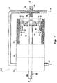
Fig. 1 is a schematic view of an exemplary embodiment of a system constructed in accordance with the present disclosure, showing a generator, transmission, and a flyweight system connected so the flyweights can govern fluid flow to the transmission; -
Fig. 2 is a perspective view of one of the flyweights ofFig. 1 , showing the magnet seated in the track; and -
Fig. 3 is a cross-sectional side elevation view of the flyweight ofFig. 2 , showing the magnet sandwiched between the base and the tab without solder. - Reference will now be made to the drawings wherein like reference numerals identify similar structural features or aspects of the subject disclosure. For purposes of explanation and illustration, and not limitation, a partial view of an exemplary embodiment of a flyweight system in accordance with the disclosure is shown in
Fig. 1 and is designated generally byreference character 100. Other embodiments of systems in accordance with the disclosure, or aspects thereof, are provided inFigs. 2-3 , as will be described. The systems and methods described herein can be used for governing flow, e.g., of transmission fluids in Integrated Drive Generators (IDGs). - The
flyweight system 100 includes a plurality offlyweights 102. Eachflyweight 102 includes abase 104. Acontrol horn 106 extends from thebase 104. Thecontrol horn 106 is connected to alinkage 108 of the flyweight governor 110. A linear actuatedvalve 112 is connected to thelinkage 108 for linear change of position of avalve member 114 of the linear actuatedvalve 112 as a function of swing position of thebase 104, as indicated inFig. 1 by the threearrows 116. Theflyweights 102 cooperate in actuation of the linear actuatedvalve 112 as theflyweights 102 revolve about a revolution axis A. The linear actuatedvalve 112 is in fluid communication in aflow line 122 between a fluid source, indicated bysource arrow 118 inFig. 1 , and atransmission 120 for control of flow rate between thefluid source 118 and thetransmission 120. Fluid can flow out of thetransmission 120 as indicated byarrow 124, e.g. to return to thesource 118 such as a sump. Agenerator 126 is connected to thetransmission 120, wherein thetransmission 120 is configured to drive thegenerator 126 given input from a prime mover, indicated schematically byarrow 128 inFig. 1 , to thetransmission 120. Thetransmission 120 is configured to drive thegenerator 126 at a relatively constant rate given variable input rate form theprime mover 128. Thetransmission 120 is connected to the flyweight governor 110 to revolve theflyweights 102 about the revolution axis A. - With reference now to
Fig. 2 , thebase 104 of eachflyweight 102 defines a through-bore 130 passing through a pair oftines 132 for connection of the base to the flyweight governor 110 shown inFig. 1 . Thebase 104 defines atrack 134 therein, which includes an open channel defined bysurfaces base 104 that is open on thetop 144, and thelateral sides 142 of the base as oriented inFig. 2 . Amagnet 146 is seated in thetrack 134 of thebase 104. The through-bore 130 runs along a pivot axis P, and thetrack 134 defines the open channel running in thebase 104 along a direction D parallel to the pivot axis P. The through-bore 130 is mounted through abearing 152 to anaxle 154 extending along the pivot axis P, as shown schematically inFig. 1 . - With reference to
Fig. 3 , atab 148 is mounted to thebase 104, sandwiching themagnet 146 between thebase 104 and thetab 148 to retain themagnet 146 in thetrack 134 without any need for solder joining themagnet 146 to thebase 104 andtab 148. Thetab 148 is mounted to thebase 104 with abolt 150 extending through thetab 148 and in threaded engagement with thebase 104. Eliminating solder also allows elimination of costly or problematic solder constituents such as gold or cadmium. - The
base 104 can include hardened steel (hardened relative to the tab 148), and thetab 148 can includes low alloy steel (low alloy relative to the base 104). The permanent magnet can include samarium-cobalt. - Referring again to
Fig. 1 , thecoils 156 in the flyweight governor 110 can generate a magnetic field from a voltage applied to thecoils 156. The magnetic field determines the swing position, indicated by thearrows 116 inFig. 1 , of theflyweights 102, allowing control of fluid flow to the transmission. - The methods and systems of the present disclosure, as described above and shown in the drawings, provide for flyweight systems with superior properties including elimination of solder from the flyweights. While the apparatus and methods of the subject disclosure have been shown and described with reference to preferred embodiments, those skilled in the art will readily appreciate that changes and/or modifications may be made thereto without departing from the scope of the subject disclosure.
Claims (15)
- A flyweight system comprising:a base (104) defining a through-bore for connection to a flyweight governor (110), wherein the base (104) defines a track (134) therein;a magnet (146) seated in the track (134) of the base (104); anda tab (148) mounted to the base (104), sandwiching the magnet (146) between the base (104) and the tab (148) to retain the magnet (146) in the track (134).
- The flyweight system as recited in claim 1, wherein the magnet (148) is devoid of solder joining it to the base (104) and tab (148).
- The flyweight system as recited in claims 1 or 2, wherein the tab (148) is mounted to the base (104) with a bolt extending through the tab (148) and in threaded engagement with the base (104).
- The flyweight system as recited in any preceding claim, wherein the base (104) includes hardened steel.
- The flyweight system as recited in any preceding claim, wherein the tab (148) includes low alloy steel.
- The flyweight system as recited in any preceding claim, wherein the magnet (146) is a permanent magnet that includes samarium-cobalt.
- The flyweight system as recited in any preceding claim, wherein the through-bore (130) runs along a pivot axis, and wherein the track (134) defines an open channel defined in the base (104) along a direction parallel to the pivot axis.
- The flyweight system as recited in any preceding claim, wherein the through-bore (130) is mounted through a bearing to an axle extending along the pivot axis.
- The flyweight system as recited in any preceding claim, further comprising a control horn (106) extending from the base (104), wherein the control horn (106) is connected to a linkage of a flyweight governor (110).
- The flyweight system as recited in claim 9, further comprising a linear actuated valve (112) connected to the linkage for linear change of position of a valve member of the linear actuated valve (112) as a function of swing position of the base (104).
- The flyweight system as recited in claim 10, wherein the base (104), flyweight, and tab (148) comprise a first flyweight and further comprising at least one additional flyweight operatively connected to the flyweight governor (110) for cooperative actuation of the linear actuated valve (42), wherein the flyweights are arranged to revolve about a revolution axis.
- The flyweight system as recited in claim 11, wherein the linear actuated valve (112) is in fluid communication between a fluid source and a transmission for control of flow rate between the fluid source and the transmission.
- The flyweight system as recited in claim 12, further comprising a generator connected to the transmission, wherein the transmission is configured to drive the generator given prime mover input to the transmission.
- The flyweight system as recited in claim 13, wherein the transmission is configured to drive the generator at a relatively constant rate given variable input rate form the prime mover.
- The flyweight system as recited in claim 14, wherein the transmission is connected to the flyweight governor (110) to revolve the flyweights about the revolution axis.
Applications Claiming Priority (1)
| Application Number | Priority Date | Filing Date | Title |
|---|---|---|---|
| US16/285,777 US10975980B2 (en) | 2019-02-26 | 2019-02-26 | Governor flyweight assemblies |
Publications (2)
| Publication Number | Publication Date |
|---|---|
| EP3702874A1 true EP3702874A1 (en) | 2020-09-02 |
| EP3702874B1 EP3702874B1 (en) | 2025-04-02 |
Family
ID=68655337
Family Applications (1)
| Application Number | Title | Priority Date | Filing Date |
|---|---|---|---|
| EP19211153.2A Active EP3702874B1 (en) | 2019-02-26 | 2019-11-25 | Governor flyweight assemblies |
Country Status (2)
| Country | Link |
|---|---|
| US (1) | US10975980B2 (en) |
| EP (1) | EP3702874B1 (en) |
Citations (3)
| Publication number | Priority date | Publication date | Assignee | Title |
|---|---|---|---|---|
| US3370600A (en) * | 1965-09-09 | 1968-02-27 | Sundstrand Corp | Centrifugal governor for dual control of a servo-motor and a hydraulic switch |
| GB1143852A (en) * | 1967-12-21 | 1969-02-26 | ||
| US4869106A (en) * | 1988-09-02 | 1989-09-26 | Sundstrand Corporation | Governor checkout apparatus and method |
Family Cites Families (4)
| Publication number | Priority date | Publication date | Assignee | Title |
|---|---|---|---|---|
| US2890877A (en) * | 1955-10-19 | 1959-06-16 | Sundstrand Machine Tool Co | Governor |
| US3831615A (en) * | 1970-08-11 | 1974-08-27 | Piqua Aircraft Co | Electrically controlled governors |
| US3751993A (en) * | 1972-06-14 | 1973-08-14 | Woodward Governor Co | Magnetic ball head speed governor |
| US8823331B2 (en) | 2011-09-15 | 2014-09-02 | Lovejoy Controls Corporation | Permanent magnet generator |
-
2019
- 2019-02-26 US US16/285,777 patent/US10975980B2/en active Active
- 2019-11-25 EP EP19211153.2A patent/EP3702874B1/en active Active
Patent Citations (3)
| Publication number | Priority date | Publication date | Assignee | Title |
|---|---|---|---|---|
| US3370600A (en) * | 1965-09-09 | 1968-02-27 | Sundstrand Corp | Centrifugal governor for dual control of a servo-motor and a hydraulic switch |
| GB1143852A (en) * | 1967-12-21 | 1969-02-26 | ||
| US4869106A (en) * | 1988-09-02 | 1989-09-26 | Sundstrand Corporation | Governor checkout apparatus and method |
Also Published As
| Publication number | Publication date |
|---|---|
| US10975980B2 (en) | 2021-04-13 |
| EP3702874B1 (en) | 2025-04-02 |
| US20200271239A1 (en) | 2020-08-27 |
Similar Documents
| Publication | Publication Date | Title |
|---|---|---|
| EP0860046B1 (en) | Rotary pump | |
| EP3449132B1 (en) | Method for detecting an abnormal operating state of a pump unit | |
| EP1727988B1 (en) | Pump | |
| DE3341716C2 (en) | ||
| DE60007584T2 (en) | Active, hydraulic, vibration-damping bearing and system containing this bearing | |
| DE3018581A1 (en) | ROTATING ELECTRICAL MACHINE | |
| EP2178581B1 (en) | Linear drive and pump system, in particular an artificial heart | |
| DE2537367A1 (en) | TURBOVACUUM PUMP | |
| DE112012005062T5 (en) | A method for realizing the dynamic equilibrium of the magnetic levitation molecular pump | |
| WO1998032214A1 (en) | Electronic starting and operating control system for a single-phase synchronous motor with a permanent magnetic rotor, also in case of failure | |
| DE102008014684A1 (en) | Turbocharger having a bearing assembly for supporting a shaft of the turbocharger | |
| DE3850851T2 (en) | Control unit for the liquid drive of a fan with an integrated speed sensor. | |
| EP0971212A1 (en) | Method to determine the pressure loss and the flow rate through a pump | |
| EP3702874B1 (en) | Governor flyweight assemblies | |
| DE2825551C3 (en) | Magnetic storage | |
| JP2012041967A (en) | Linear solenoid control device | |
| DE102013008793B4 (en) | Method and device for adjusting a variable displacement pump in the open hydraulic circuit | |
| DE102008035086B4 (en) | Turbocharger having a magnetic bearing assembly for supporting a shaft of the turbocharger and a method for supporting the shaft | |
| DE112007000140T5 (en) | drive system | |
| DE112019000807B4 (en) | Linear compressor and linear compressor control system | |
| EP3900159A1 (en) | Electric motor with different star points | |
| EP2354557B1 (en) | Device with a stator and a rotor laid within the stator | |
| EP3683449B1 (en) | Magnetic bearing and vacuum apparatus | |
| DE102014225534B3 (en) | Method for optimizing a drive dynamics of an electric motor, preferably for use in a hydrostatic clutch actuator of a motor vehicle | |
| EP3653884B1 (en) | Vacuum pump |
Legal Events
| Date | Code | Title | Description |
|---|---|---|---|
| PUAI | Public reference made under article 153(3) epc to a published international application that has entered the european phase |
Free format text: ORIGINAL CODE: 0009012 |
|
| STAA | Information on the status of an ep patent application or granted ep patent |
Free format text: STATUS: THE APPLICATION HAS BEEN PUBLISHED |
|
| AK | Designated contracting states |
Kind code of ref document: A1 Designated state(s): AL AT BE BG CH CY CZ DE DK EE ES FI FR GB GR HR HU IE IS IT LI LT LU LV MC MK MT NL NO PL PT RO RS SE SI SK SM TR |
|
| AX | Request for extension of the european patent |
Extension state: BA ME |
|
| STAA | Information on the status of an ep patent application or granted ep patent |
Free format text: STATUS: REQUEST FOR EXAMINATION WAS MADE |
|
| 17P | Request for examination filed |
Effective date: 20210302 |
|
| RBV | Designated contracting states (corrected) |
Designated state(s): AL AT BE BG CH CY CZ DE DK EE ES FI FR GB GR HR HU IE IS IT LI LT LU LV MC MK MT NL NO PL PT RO RS SE SI SK SM TR |
|
| STAA | Information on the status of an ep patent application or granted ep patent |
Free format text: STATUS: EXAMINATION IS IN PROGRESS |
|
| 17Q | First examination report despatched |
Effective date: 20220225 |
|
| GRAP | Despatch of communication of intention to grant a patent |
Free format text: ORIGINAL CODE: EPIDOSNIGR1 |
|
| STAA | Information on the status of an ep patent application or granted ep patent |
Free format text: STATUS: GRANT OF PATENT IS INTENDED |
|
| INTG | Intention to grant announced |
Effective date: 20240515 |
|
| GRAJ | Information related to disapproval of communication of intention to grant by the applicant or resumption of examination proceedings by the epo deleted |
Free format text: ORIGINAL CODE: EPIDOSDIGR1 |
|
| STAA | Information on the status of an ep patent application or granted ep patent |
Free format text: STATUS: EXAMINATION IS IN PROGRESS |
|
| GRAP | Despatch of communication of intention to grant a patent |
Free format text: ORIGINAL CODE: EPIDOSNIGR1 |
|
| STAA | Information on the status of an ep patent application or granted ep patent |
Free format text: STATUS: GRANT OF PATENT IS INTENDED |
|
| INTC | Intention to grant announced (deleted) | ||
| INTG | Intention to grant announced |
Effective date: 20240710 |
|
| GRAJ | Information related to disapproval of communication of intention to grant by the applicant or resumption of examination proceedings by the epo deleted |
Free format text: ORIGINAL CODE: EPIDOSDIGR1 |
|
| STAA | Information on the status of an ep patent application or granted ep patent |
Free format text: STATUS: EXAMINATION IS IN PROGRESS |
|
| GRAP | Despatch of communication of intention to grant a patent |
Free format text: ORIGINAL CODE: EPIDOSNIGR1 |
|
| STAA | Information on the status of an ep patent application or granted ep patent |
Free format text: STATUS: GRANT OF PATENT IS INTENDED |
|
| INTC | Intention to grant announced (deleted) | ||
| INTG | Intention to grant announced |
Effective date: 20241112 |
|
| GRAS | Grant fee paid |
Free format text: ORIGINAL CODE: EPIDOSNIGR3 |
|
| GRAA | (expected) grant |
Free format text: ORIGINAL CODE: 0009210 |
|
| STAA | Information on the status of an ep patent application or granted ep patent |
Free format text: STATUS: THE PATENT HAS BEEN GRANTED |
|
| AK | Designated contracting states |
Kind code of ref document: B1 Designated state(s): AL AT BE BG CH CY CZ DE DK EE ES FI FR GB GR HR HU IE IS IT LI LT LU LV MC MK MT NL NO PL PT RO RS SE SI SK SM TR |
|
| REG | Reference to a national code |
Ref country code: GB Ref legal event code: FG4D |
|
| REG | Reference to a national code |
Ref country code: CH Ref legal event code: EP |
|
| REG | Reference to a national code |
Ref country code: DE Ref legal event code: R096 Ref document number: 602019068027 Country of ref document: DE |
|
| REG | Reference to a national code |
Ref country code: IE Ref legal event code: FG4D |
|
| REG | Reference to a national code |
Ref country code: NL Ref legal event code: MP Effective date: 20250402 |
|
| PG25 | Lapsed in a contracting state [announced via postgrant information from national office to epo] |
Ref country code: NL Free format text: LAPSE BECAUSE OF FAILURE TO SUBMIT A TRANSLATION OF THE DESCRIPTION OR TO PAY THE FEE WITHIN THE PRESCRIBED TIME-LIMIT Effective date: 20250402 |
|
| REG | Reference to a national code |
Ref country code: AT Ref legal event code: MK05 Ref document number: 1781882 Country of ref document: AT Kind code of ref document: T Effective date: 20250402 |
|
| PG25 | Lapsed in a contracting state [announced via postgrant information from national office to epo] |
Ref country code: PT Free format text: LAPSE BECAUSE OF FAILURE TO SUBMIT A TRANSLATION OF THE DESCRIPTION OR TO PAY THE FEE WITHIN THE PRESCRIBED TIME-LIMIT Effective date: 20250804 Ref country code: ES Free format text: LAPSE BECAUSE OF FAILURE TO SUBMIT A TRANSLATION OF THE DESCRIPTION OR TO PAY THE FEE WITHIN THE PRESCRIBED TIME-LIMIT Effective date: 20250402 Ref country code: FI Free format text: LAPSE BECAUSE OF FAILURE TO SUBMIT A TRANSLATION OF THE DESCRIPTION OR TO PAY THE FEE WITHIN THE PRESCRIBED TIME-LIMIT Effective date: 20250402 |
|
| REG | Reference to a national code |
Ref country code: LT Ref legal event code: MG9D |
|
| PG25 | Lapsed in a contracting state [announced via postgrant information from national office to epo] |
Ref country code: NO Free format text: LAPSE BECAUSE OF FAILURE TO SUBMIT A TRANSLATION OF THE DESCRIPTION OR TO PAY THE FEE WITHIN THE PRESCRIBED TIME-LIMIT Effective date: 20250702 Ref country code: GR Free format text: LAPSE BECAUSE OF FAILURE TO SUBMIT A TRANSLATION OF THE DESCRIPTION OR TO PAY THE FEE WITHIN THE PRESCRIBED TIME-LIMIT Effective date: 20250703 |
|
| PG25 | Lapsed in a contracting state [announced via postgrant information from national office to epo] |
Ref country code: PL Free format text: LAPSE BECAUSE OF FAILURE TO SUBMIT A TRANSLATION OF THE DESCRIPTION OR TO PAY THE FEE WITHIN THE PRESCRIBED TIME-LIMIT Effective date: 20250402 |
|
| PG25 | Lapsed in a contracting state [announced via postgrant information from national office to epo] |
Ref country code: BG Free format text: LAPSE BECAUSE OF FAILURE TO SUBMIT A TRANSLATION OF THE DESCRIPTION OR TO PAY THE FEE WITHIN THE PRESCRIBED TIME-LIMIT Effective date: 20250402 |
|
| PG25 | Lapsed in a contracting state [announced via postgrant information from national office to epo] |
Ref country code: HR Free format text: LAPSE BECAUSE OF FAILURE TO SUBMIT A TRANSLATION OF THE DESCRIPTION OR TO PAY THE FEE WITHIN THE PRESCRIBED TIME-LIMIT Effective date: 20250402 |
|
| PG25 | Lapsed in a contracting state [announced via postgrant information from national office to epo] |
Ref country code: AT Free format text: LAPSE BECAUSE OF FAILURE TO SUBMIT A TRANSLATION OF THE DESCRIPTION OR TO PAY THE FEE WITHIN THE PRESCRIBED TIME-LIMIT Effective date: 20250402 |
|
| PG25 | Lapsed in a contracting state [announced via postgrant information from national office to epo] |
Ref country code: RS Free format text: LAPSE BECAUSE OF FAILURE TO SUBMIT A TRANSLATION OF THE DESCRIPTION OR TO PAY THE FEE WITHIN THE PRESCRIBED TIME-LIMIT Effective date: 20250702 |
|
| PG25 | Lapsed in a contracting state [announced via postgrant information from national office to epo] |
Ref country code: IS Free format text: LAPSE BECAUSE OF FAILURE TO SUBMIT A TRANSLATION OF THE DESCRIPTION OR TO PAY THE FEE WITHIN THE PRESCRIBED TIME-LIMIT Effective date: 20250802 |
|
| PG25 | Lapsed in a contracting state [announced via postgrant information from national office to epo] |
Ref country code: LV Free format text: LAPSE BECAUSE OF FAILURE TO SUBMIT A TRANSLATION OF THE DESCRIPTION OR TO PAY THE FEE WITHIN THE PRESCRIBED TIME-LIMIT Effective date: 20250402 |
|
| REG | Reference to a national code |
Ref country code: DE Ref legal event code: R097 Ref document number: 602019068027 Country of ref document: DE |
|
| PG25 | Lapsed in a contracting state [announced via postgrant information from national office to epo] |
Ref country code: DK Free format text: LAPSE BECAUSE OF FAILURE TO SUBMIT A TRANSLATION OF THE DESCRIPTION OR TO PAY THE FEE WITHIN THE PRESCRIBED TIME-LIMIT Effective date: 20250402 Ref country code: SM Free format text: LAPSE BECAUSE OF FAILURE TO SUBMIT A TRANSLATION OF THE DESCRIPTION OR TO PAY THE FEE WITHIN THE PRESCRIBED TIME-LIMIT Effective date: 20250402 |
|
| PGFP | Annual fee paid to national office [announced via postgrant information from national office to epo] |
Ref country code: FR Payment date: 20251022 Year of fee payment: 7 |
|
| PG25 | Lapsed in a contracting state [announced via postgrant information from national office to epo] |
Ref country code: CZ Free format text: LAPSE BECAUSE OF FAILURE TO SUBMIT A TRANSLATION OF THE DESCRIPTION OR TO PAY THE FEE WITHIN THE PRESCRIBED TIME-LIMIT Effective date: 20250402 |
|
| PG25 | Lapsed in a contracting state [announced via postgrant information from national office to epo] |
Ref country code: EE Free format text: LAPSE BECAUSE OF FAILURE TO SUBMIT A TRANSLATION OF THE DESCRIPTION OR TO PAY THE FEE WITHIN THE PRESCRIBED TIME-LIMIT Effective date: 20250402 |
|
| PG25 | Lapsed in a contracting state [announced via postgrant information from national office to epo] |
Ref country code: SK Free format text: LAPSE BECAUSE OF FAILURE TO SUBMIT A TRANSLATION OF THE DESCRIPTION OR TO PAY THE FEE WITHIN THE PRESCRIBED TIME-LIMIT Effective date: 20250402 Ref country code: RO Free format text: LAPSE BECAUSE OF FAILURE TO SUBMIT A TRANSLATION OF THE DESCRIPTION OR TO PAY THE FEE WITHIN THE PRESCRIBED TIME-LIMIT Effective date: 20250402 |
|
| PG25 | Lapsed in a contracting state [announced via postgrant information from national office to epo] |
Ref country code: IT Free format text: LAPSE BECAUSE OF FAILURE TO SUBMIT A TRANSLATION OF THE DESCRIPTION OR TO PAY THE FEE WITHIN THE PRESCRIBED TIME-LIMIT Effective date: 20250402 |
|
| PLBE | No opposition filed within time limit |
Free format text: ORIGINAL CODE: 0009261 |
|
| STAA | Information on the status of an ep patent application or granted ep patent |
Free format text: STATUS: NO OPPOSITION FILED WITHIN TIME LIMIT |
|
| REG | Reference to a national code |
Ref country code: CH Ref legal event code: L10 Free format text: ST27 STATUS EVENT CODE: U-0-0-L10-L00 (AS PROVIDED BY THE NATIONAL OFFICE) Effective date: 20260211 |
|
| 26N | No opposition filed |
Effective date: 20260105 |