EP3702867B1 - Server and vehicle control system - Google Patents
Server and vehicle control system Download PDFInfo
- Publication number
- EP3702867B1 EP3702867B1 EP20159768.9A EP20159768A EP3702867B1 EP 3702867 B1 EP3702867 B1 EP 3702867B1 EP 20159768 A EP20159768 A EP 20159768A EP 3702867 B1 EP3702867 B1 EP 3702867B1
- Authority
- EP
- European Patent Office
- Prior art keywords
- trajectory
- vehicle
- traveling
- traveling trajectory
- information
- Prior art date
- Legal status (The legal status is an assumption and is not a legal conclusion. Google has not performed a legal analysis and makes no representation as to the accuracy of the status listed.)
- Active
Links
Images


Classifications
-
- B—PERFORMING OPERATIONS; TRANSPORTING
- B60—VEHICLES IN GENERAL
- B60W—CONJOINT CONTROL OF VEHICLE SUB-UNITS OF DIFFERENT TYPE OR DIFFERENT FUNCTION; CONTROL SYSTEMS SPECIALLY ADAPTED FOR HYBRID VEHICLES; ROAD VEHICLE DRIVE CONTROL SYSTEMS FOR PURPOSES NOT RELATED TO THE CONTROL OF A PARTICULAR SUB-UNIT
- B60W60/00—Drive control systems specially adapted for autonomous road vehicles
- B60W60/001—Planning or execution of driving tasks
- B60W60/0011—Planning or execution of driving tasks involving control alternatives for a single driving scenario, e.g. planning several paths to avoid obstacles
-
- G—PHYSICS
- G05—CONTROLLING; REGULATING
- G05D—SYSTEMS FOR CONTROLLING OR REGULATING NON-ELECTRIC VARIABLES
- G05D1/00—Control of position, course, altitude or attitude of land, water, air or space vehicles, e.g. using automatic pilots
- G05D1/02—Control of position or course in two dimensions
- G05D1/021—Control of position or course in two dimensions specially adapted to land vehicles
- G05D1/0276—Control of position or course in two dimensions specially adapted to land vehicles using signals provided by a source external to the vehicle
- G05D1/028—Control of position or course in two dimensions specially adapted to land vehicles using signals provided by a source external to the vehicle using a RF signal
- G05D1/0282—Control of position or course in two dimensions specially adapted to land vehicles using signals provided by a source external to the vehicle using a RF signal generated in a local control room
-
- B—PERFORMING OPERATIONS; TRANSPORTING
- B60—VEHICLES IN GENERAL
- B60W—CONJOINT CONTROL OF VEHICLE SUB-UNITS OF DIFFERENT TYPE OR DIFFERENT FUNCTION; CONTROL SYSTEMS SPECIALLY ADAPTED FOR HYBRID VEHICLES; ROAD VEHICLE DRIVE CONTROL SYSTEMS FOR PURPOSES NOT RELATED TO THE CONTROL OF A PARTICULAR SUB-UNIT
- B60W40/00—Estimation or calculation of non-directly measurable driving parameters for road vehicle drive control systems not related to the control of a particular sub unit, e.g. by using mathematical models
-
- B—PERFORMING OPERATIONS; TRANSPORTING
- B60—VEHICLES IN GENERAL
- B60W—CONJOINT CONTROL OF VEHICLE SUB-UNITS OF DIFFERENT TYPE OR DIFFERENT FUNCTION; CONTROL SYSTEMS SPECIALLY ADAPTED FOR HYBRID VEHICLES; ROAD VEHICLE DRIVE CONTROL SYSTEMS FOR PURPOSES NOT RELATED TO THE CONTROL OF A PARTICULAR SUB-UNIT
- B60W40/00—Estimation or calculation of non-directly measurable driving parameters for road vehicle drive control systems not related to the control of a particular sub unit, e.g. by using mathematical models
- B60W40/02—Estimation or calculation of non-directly measurable driving parameters for road vehicle drive control systems not related to the control of a particular sub unit, e.g. by using mathematical models related to ambient conditions
-
- G—PHYSICS
- G05—CONTROLLING; REGULATING
- G05D—SYSTEMS FOR CONTROLLING OR REGULATING NON-ELECTRIC VARIABLES
- G05D1/00—Control of position, course, altitude or attitude of land, water, air or space vehicles, e.g. using automatic pilots
- G05D1/02—Control of position or course in two dimensions
- G05D1/021—Control of position or course in two dimensions specially adapted to land vehicles
- G05D1/0212—Control of position or course in two dimensions specially adapted to land vehicles with means for defining a desired trajectory
- G05D1/0214—Control of position or course in two dimensions specially adapted to land vehicles with means for defining a desired trajectory in accordance with safety or protection criteria, e.g. avoiding hazardous areas
-
- G—PHYSICS
- G08—SIGNALLING
- G08G—TRAFFIC CONTROL SYSTEMS
- G08G1/00—Traffic control systems for road vehicles
- G08G1/09—Arrangements for giving variable traffic instructions
- G08G1/0962—Arrangements for giving variable traffic instructions having an indicator mounted inside the vehicle, e.g. giving voice messages
- G08G1/0968—Systems involving transmission of navigation instructions to the vehicle
- G08G1/096805—Systems involving transmission of navigation instructions to the vehicle where the transmitted instructions are used to compute a route
- G08G1/096827—Systems involving transmission of navigation instructions to the vehicle where the transmitted instructions are used to compute a route where the route is computed onboard
-
- G—PHYSICS
- G08—SIGNALLING
- G08G—TRAFFIC CONTROL SYSTEMS
- G08G1/00—Traffic control systems for road vehicles
- G08G1/09—Arrangements for giving variable traffic instructions
- G08G1/0962—Arrangements for giving variable traffic instructions having an indicator mounted inside the vehicle, e.g. giving voice messages
- G08G1/0968—Systems involving transmission of navigation instructions to the vehicle
- G08G1/096833—Systems involving transmission of navigation instructions to the vehicle where different aspects are considered when computing the route
- G08G1/096844—Systems involving transmission of navigation instructions to the vehicle where different aspects are considered when computing the route where the complete route is dynamically recomputed based on new data
-
- H—ELECTRICITY
- H04—ELECTRIC COMMUNICATION TECHNIQUE
- H04W—WIRELESS COMMUNICATION NETWORKS
- H04W4/00—Services specially adapted for wireless communication networks; Facilities therefor
- H04W4/30—Services specially adapted for particular environments, situations or purposes
- H04W4/40—Services specially adapted for particular environments, situations or purposes for vehicles, e.g. vehicle-to-pedestrians [V2P]
-
- B—PERFORMING OPERATIONS; TRANSPORTING
- B60—VEHICLES IN GENERAL
- B60W—CONJOINT CONTROL OF VEHICLE SUB-UNITS OF DIFFERENT TYPE OR DIFFERENT FUNCTION; CONTROL SYSTEMS SPECIALLY ADAPTED FOR HYBRID VEHICLES; ROAD VEHICLE DRIVE CONTROL SYSTEMS FOR PURPOSES NOT RELATED TO THE CONTROL OF A PARTICULAR SUB-UNIT
- B60W2555/00—Input parameters relating to exterior conditions, not covered by groups B60W2552/00, B60W2554/00
- B60W2555/20—Ambient conditions, e.g. wind or rain
-
- B—PERFORMING OPERATIONS; TRANSPORTING
- B60—VEHICLES IN GENERAL
- B60W—CONJOINT CONTROL OF VEHICLE SUB-UNITS OF DIFFERENT TYPE OR DIFFERENT FUNCTION; CONTROL SYSTEMS SPECIALLY ADAPTED FOR HYBRID VEHICLES; ROAD VEHICLE DRIVE CONTROL SYSTEMS FOR PURPOSES NOT RELATED TO THE CONTROL OF A PARTICULAR SUB-UNIT
- B60W2556/00—Input parameters relating to data
- B60W2556/45—External transmission of data to or from the vehicle
- B60W2556/50—External transmission of data to or from the vehicle of positioning data, e.g. GPS [Global Positioning System] data
-
- G—PHYSICS
- G08—SIGNALLING
- G08G—TRAFFIC CONTROL SYSTEMS
- G08G1/00—Traffic control systems for road vehicles
- G08G1/16—Anti-collision systems
Definitions
- the present invention relates to a vehicle control system.
- JP 2018-531385 A discloses a data processing system for determining an optimal route by executing, in view of physical characteristics of an autonomous vehicle, a simulation of a route on each of routes being described in motion planning and control data indicating that the autonomous vehicle is to move from a first point to a second point and extending from the first point to the second point.
- US 2017/315551 A1 shows a vehicle control system including an automated drive control unit that performs automated driving wherein the automated drive control unit executes a handover where an automated driving mode is switched to a manual driving mode, a calculating unit that calculates an occurrence frequency of the handover or an occurrence probability of the handover on a traveling route that the vehicle will travel.
- the determination of the optimal traveling trajectory for the vehicle to perform autonomous movement may be affected not only by the physical characteristics of the vehicle but also by an ambient environment of the vehicle. Therefore, in a case where the ambient environment changes with the lapse of time, even a traveling trajectory determined as optimal once is not always optimal at a timing when the vehicle actually travels.
- JP 2018-531385 A even in a case where the traveling trajectory that has been set once becomes non-optimal due to changes in the ambient environment, it is impossible to reset the optimal traveling trajectory.
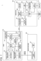
- FIG. 1 is a view illustrating a configuration of a vehicle control system according to a first embodiment of the present invention.
- a vehicle control system 1 illustrated in Fig. 1 includes a server 100, an infrastructure sensor 200, and an onboard device 300.
- the vehicle control system 1 performs a control to set, for a vehicle on which the onboard device 300 is mounted, a traveling trajectory leading to a designated point and to cause the vehicle to move autonomously.
- the vehicle that is to be controlled by the vehicle control system 1, i.e., the vehicle on which the onboard device 300 is mounted is referred to as a "target vehicle".
- the server 100 is information equipment for setting a traveling trajectory along which the target vehicle is caused to move autonomously and transmitting the traveling trajectory to the target vehicle.
- the server 100 is installed in a predetermined facility, such as an information center.
- the server 100 includes functional blocks including a vehicle position management part 101, a candidate trajectory generation part 102, map information 103, an infrastructure coordination part 104, an ambient environment generation part 105, a vehicle characteristic information storage part 106, a trajectory simulator 107, a trajectory evaluation part 108, a vehicle coordination part 109, and a resetting determination part 110.
- the server 100 has a hardware structure including a CPU, a memory, and a storage (e.g., HDD, SSD), each of which is not illustrated. With use of these pieces of hardware, the server 100 executes a predetermined program to achieve the functional blocks described above.
- the infrastructure sensor 200 is installed near the traveling trajectory that is to be set by the server 100.
- the infrastructure sensor 200 detects, at a location outside the target vehicle, an obstacle existing in an area surrounding the traveling trajectory.
- Fig. 1 shows only one infrastructure sensor 200.
- a plurality of infrastructure sensors 200 may be installed near the traveling trajectory.
- the infrastructure sensor 200 includes functional blocks including a sensor part 201 and an infrastructure-side server coordination part 202.
- the onboard device 300 is installed on the target vehicle.
- the onboard device 300 performs a control required to cause the target vehicle to move autonomously to the designated point along the traveling trajectory provided by the server 100.
- Fig. 1 shows only one onboard device 300.
- two or more vehicles may include their respective onboard devices 300, each of which constitutes the vehicle control system 1 in combination with the server 100 and the infrastructure sensor 200.
- the onboard device 300 includes functional blocks including a vehicle-side server coordination part 301, a trajectory management part 302, a determination part 303, a vehicle-side display control part 304, a vehicle-side display part 305, map information 306, a vehicle position determination part 307, and a vehicle control part 308.
- the vehicle position management part 101 manages positions of the vehicles on which the onboard devices 300 are mounted.
- the vehicle position management part 101 manages the positions of the vehicles by storing and retaining pieces of position information of the vehicles in association with unique vehicles IDs preliminarily assigned to the vehicles.
- the positions of the vehicles are uprated as appropriate according to pieces of position information supplied from the onboard device 300.
- the candidate trajectory generation part 102 uses the map information 103 to generate a candidate traveling trajectory, which is a candidate of a traveling trajectory along which the target vehicle is caused to move autonomously.
- the candidate trajectory generation part 102 obtains information indicating a current position of the target vehicle from the onboard device 300, and generates a plurality of candidate traveling trajectories used to cause the target vehicle to move autonomously from the obtained current position to a designated parking position and to park the target vehicle at the designated parking position.
- the candidate traveling trajectories may be generated with use of information indicating an ambient environment of the target vehicle generated by the ambient environment generation part 105 based on sensing information obtained from the infrastructure sensor 200 and/or various information (e.g., traffic information, weather information) obtained externally.
- the candidate traveling trajectories generated by the candidate trajectory generation part 102 may include a traveling trajectory along which the target vehicle cannot actually travel (e.g., a candidate traveling trajectory including an obstacle in its midway, a traveling trajectory in which the target vehicle cannot be steered).
- the map information 103 is information indicating a map of a region in which the target vehicle moves autonomously.
- the map information 103 is stored in a storage, such as HDD or SDD, in the server 100.
- the map information 103 includes road map information of various areas in the country, map information of the areas inside car parks, and/or the like.
- the map information 103 is preferably the one that is more precise than map information generally used in conventional navigation devices and/or the like.
- the infrastructure coordination part 104 has a communication function to communicate with the infrastructure sensor 200.
- the infrastructure coordination part 104 receives information from the infrastructure sensor 200 and to transmit information to the infrastructure sensor 200.
- the infrastructure coordination part 104 can communicate with the infrastructure sensor 200, e.g., via a mobile communication network (4G, 5G) or a fixed line.
- the ambient environment generation part 105 generates information indicating an ambient environment of the target vehicle and the traveling trajectory based on the sensing information transmitted from the infrastructure sensor 200 and received by the infrastructure coordination part 104.
- the information indicating the ambient environment generated by the ambient environment generation part 105 can be obtained by performing a predetermined calculating process with use of the sensing information transmitted from the infrastructure sensor 200, the sensing information being information indicating the positions, sizes, shapes, and/or the like of various obstacles and background objects (e.g., other vehicles, parked vehicles, pedestrians, bicycles, traffic signals, telegraph poles, road signs, street trees, and signboards) existing around the target vehicle and/or the traveling trajectory.
- the information indicating the ambient environment may be generated by any method, as long as the method can generate ambient environment information that can accurately represent at least an obstacle interfering with the traveling trajectory, if present.
- the vehicle characteristic information storage part 106 stores and retains characteristic information of various vehicles including the target vehicle.
- the characteristic information is information indicating characteristics of the vehicles related to autonomous movement, and includes information indicating the sizes, weights, yaw inertia moments, distances between axles, gravity center positions, and cornering power, for example.
- the trajectory simulator 107 executes, on each of the candidate traveling trajectories generated by the candidate trajectory generation part 102, a trajectory simulation involving use of the characteristic information of the target vehicle stored in the vehicle characteristic information storage part 106.
- the trajectory simulator 107 performs the trajectory simulation by calculating behaviors of the target vehicle that is moving autonomously along each of the candidate traveling trajectories with use of, e.g., the map information 103 and/or the information indicating the ambient environment generated by the ambient environment generation part 105.
- the trajectory simulation may be performed in consideration of external factors, such as the conditions of a road surface and/or behaviors of an obstacle existing in its surrounding area.
- the trajectory evaluation part 108 determines a traveling trajectory along which the target vehicle is caused to move autonomously, based on the results of the trajectory simulations performed by the trajectory simulator 107. For example, the trajectory evaluation part 108 sets evaluation values on the candidate traveling trajectories based on the behaviors of the target vehicle in the candidate traveling trajectories obtained as a result of the trajectory simulations, and determines, as a traveling trajectory of the target vehicle, a candidate traveling trajectory having the lowest evaluation value, i.e., a candidate traveling trajectory that gives the lowest load on the target vehicle.
- the evaluation may be performed by any method, as long as the method can determine a traveling trajectory from among the plurality of candidate traveling trajectories based on the results of the trajectory simulations.
- the vehicle coordination part 109 has a communication function to communicate with the onboard device 300.
- the vehicle coordination part 109 receives the position information of the target vehicle from the onboard device 300, and transmits the information of the traveling trajectory determined by the trajectory evaluation part 108 to the onboard device 300.
- the vehicle coordination part 109 can communicate with the onboard device 300, e.g., via a mobile communication network (4G, 5G).
- the resetting determination part 110 determines whether to reset the traveling trajectory determined by the trajectory evaluation part 108, based on the current situation of the target vehicle. If the resetting determination part 110 determines to reset the traveling trajectory, the server 100 executes, via the trajectory simulator 107, trajectory simulations again. Then, the server 100 determines, via the trajectory evaluation part 108, a new traveling trajectory of the target vehicle based on the result of the trajectory simulation. Then, the vehicle coordination part 109 transmits the information of the new traveling trajectory thus determined to the onboard device 300. The method how the resetting determination part 110 determines whether to reset the traveling trajectory will be described in detail later.
- the sensor part 201 is constituted by various sensors, such as a camera, a radar, light detection and ranging (LiDAR).
- the sensor part 201 generates sensing information corresponding to a predetermined sensing range of the sensors based on the position where the infrastructure sensor 200 is installed.
- the sensing information includes information of an obstacle existing in the sensing range.
- the infrastructure-side server coordination part 202 has a communication function to communicate with the server 100.
- the infrastructure-side server coordination part 202 transmits the sensing information generated by the sensor part 201 to the server 100.
- the infrastructure-side server coordination part 202 can communicate with the infrastructure coordination part 104 of the server 100, e.g., via a mobile communication network (4G, 5G) or a fixed line.
- the vehicle-side server coordination part 301 has a communication function to communicate with the server 100.
- the vehicle-side server coordination part 301 transmits the position information of the target vehicle to the server 100, and receives the information on the traveling trajectory transmitted from the server 100.
- the vehicle-side server coordination part 301 can communicate with the vehicle coordination part 109 of the server 100, e.g., via a mobile communication network (4G, 5G).
- the trajectory management part 302 manages the traveling trajectory along which the target vehicle moves autonomously according to the information on the traveling trajectory transmitted from the server 100. If the resetting determination part 110 in the server 100 determines to reset the traveling trajectory in the above-described manner and accordingly a new traveling trajectory determined is transmitted from the server 100 and received by the vehicle-side server coordination part 301, the trajectory management part 302 discards the existing traveling trajectory and sets the new traveling trajectory according to the received information.
- the determination part 303 determines a motion required to cause the target vehicle to move autonomously along the traveling trajectory managed by the trajectory management part 302, based on the map information 306 and information indicating the current position of the target vehicle determined by the vehicle position determination part 307. For example, the determination part 303 determines the speed, the acceleration, and the steering amount of the target vehicle based on the length and/or the curvature of the traveling trajectory. The determination may be made further based on information on an area surrounding the target vehicle obtained from an onboard sensor 31. For example, if an obstacle existing in front of the target vehicle is detected, a determination may be made to apply emergency braking.
- the vehicle-side display control part 304 generates a screen to be displayed on the vehicle-side display part 305, based on the map information 306, the traveling trajectory managed by the trajectory management part 302, and the determination result of the determination part 303.
- the vehicle-side display part 305 is made of a liquid crystal display, for example.
- the vehicle-side display part 305 displays the screen generated by the vehicle-side display control part 304 to give a notification to a passenger on the target vehicle.
- the vehicle-side display part 305 displays a screen indicating a traveling trajectory on a map or a screen notifying the passenger on the target vehicle of the fact that the traveling trajectory has been reset or the fact that an obstacle has been detected, if this happens.
- a sound from a speaker may be used in combination with or instead of the screen on the vehicle-side display part 305 to give a notification to the passenger.
- the map information 306 is information indicating a map of a region where the target vehicle moves autonomously, and is stored in a not-illustrated storage (e.g., HDD, SDD) in the onboard device 300.
- the map information 306 is used by the determination part 303 to make a determination on a motion of the target vehicle and/or by the vehicle-side display control part 304 to generate a map screen, for example.
- the map information 306 is preferably the one that is more precise than a generally-used conventional map.
- the vehicle position determination part 307 determines the position of the target vehicle based on a GPS signal received by a GPS sensor (not illustrated) and/or information (e.g., a speed, an acceleration, a steering amount) about an operating state of the target vehicle detected by the onboard sensor 31.
- the map information 306 may be used to perform a well-known map matching process to position the target vehicle on a road.
- the position information of the target vehicle determined by the vehicle position determination part 307 is transmitted to the server 100 by the vehicle-side server coordination part 301, and is used by the vehicle position management part 101 to manage the position of the target vehicle.
- the vehicle control part 308 performs a control on the target vehicle based on the result of the determination on the motion of the target vehicle which determination has been made by the determination part 303.
- the vehicle control part 308 is connected to a driving part 32 of the target vehicle.
- the vehicle control part 308 controls the driving part 32 to execute an acceleration operation, a braking operation, a steering operation, or the like of the target vehicle. In this manner, the vehicle control part 308 controls the operating state of the target vehicle according to the determination result of the determination part 303.
- Fig. 2 is a sequence diagram of the autonomous movement control performed by the vehicle control system 1.
- step S101 the onboard device 300 transmits, via the vehicle-side server coordination part 301, a request on a traveling trajectory to the server 100.
- the onboard device 300 transmits the request on the traveling trajectory to the server 100 by executing step S101, if the passenger on the target vehicle gives an instruction to execute automatic parking or automatic driving or a determination or if a new traveling trajectory is determined to be necessary during automatic driving, for example.
- the request on the traveling trajectory includes information indicating a target point (e.g., a parking position, a point where a control for automatic driving is performed), which is a destination of the autonomous movement of the target vehicle.
- the server 100 receives, via the vehicle coordination part 109, the request on the traveling trajectory transmitted from the onboard device 300.
- step S102 the infrastructure sensor 200 transmits, via the infrastructure-side server coordination part 202, the sensing information generated by the sensor part 201 to the server 100.
- the server 100 receives, via the infrastructure coordination part 104, the sensing information transmitted from the infrastructure sensor 200.
- step S103 the server 100 generates, via the ambient environment generation part 105, information indicating an ambient environment of the target vehicle, based on the sensing information received from the infrastructure sensor 200 in step S102.
- step S104 the server 100 generates, via the candidate trajectory generation part 102, candidate traveling trajectories from which the traveling trajectory is obtained.
- the candidate trajectory generation part 102 obtains the information indicating the current position of the target vehicle from the vehicle position management part 101, and generates a plurality of candidate traveling trajectories located between the current position and the target point included in the request received in step S101.
- step S105 the server 100 obtains, via the trajectory simulator 107, characteristic information of the target vehicle from the vehicle characteristic information storage part 106.
- the trajectory simulator 107 obtains, as the characteristic information of the target vehicle, a piece of characteristic information of a vehicle including the onboard device 300 that has transmitted the request on the traveling trajectory in step S101, from among the pieces of characteristic information of the vehicles stored in the vehicle characteristic information storage part 106.
- step S106 the server 100 executes, via the trajectory simulator 107, a trajectory simulation on each of the candidate traveling trajectories generated in step S104.
- the trajectory simulator 107 executes a trajectory simulation of calculating behaviors of the target vehicle that is moving autonomously along each of the candidate traveling trajectories, based on the information indicating the ambient environment generated in step S103 and the characteristic information of the target vehicle obtained in step S105.
- step S107 the server 100 performs, via the trajectory evaluation part 108, trajectory evaluations on the results of the trajectory simulations executed in step S106.
- the trajectory evaluation part 108 sets evaluation values on the candidate traveling trajectories based on the behaviors of the target vehicle in the candidate traveling trajectories obtained as a result of the trajectory simulations in the above-described manner, for example. Then, the trajectory evaluation part 108 determines, as the traveling trajectory of the target vehicle, a candidate traveling trajectory whose evaluation value is lower than those of any other candidate traveling trajectories.
- step S108 the server 100 transmits, via the vehicle coordination part 109, the information of the traveling trajectory determined in step S107 to the onboard device 300.
- the onboard device 300 receives, via the vehicle-side server coordination part 301, the traveling trajectory information transmitted from the server 100.
- step S109 the onboard device 300 executes a control for causing the target vehicle to move autonomously following the traveling trajectory, based on the traveling trajectory information received from the server 100 in step S108.
- the onboard device 300 causes the trajectory management part 302 to store and retain the received traveling trajectory information, and causes the determination part 303 and the vehicle control part 308 to control the operating state of the target vehicle. In this manner, the onboard device 300 causes the target vehicle to move autonomously following the traveling trajectory.
- step S110 the onboard device 300 determines, via the determination part 303, whether to give up the autonomous movement of the target vehicle. In this process, during the control in step S109, the onboard device 300 determines whether or not the target vehicle cannot move autonomously along the traveling trajectory any more. If the onboard device 300 determines that such a situation occurs, the onboard device 300 determines to give up the autonomous movement of the target vehicle.
- This situation may be, for example, a situation where the onboard sensor 31 detects an obstacle on the traveling trajectory, a situation where the target vehicle is away from the traveling trajectory by a predetermined distance or more, or a situation where it is determined that the target vehicle cannot be steered.
- the passenger on the target vehicle may perform a predetermined operation with respect to the onboard device 300 to choose giving up. If any of these situations occurs, the onboard device 300 determines to give up the autonomous movement of the target vehicle, and stops the control performed in step S109. Then, the process advances to step Sill. Meanwhile, if none of these situations occurs, the onboard device 300 determines to continue the control performed in step S109, rather than giving up. Then, the process advances to step S112.
- step Sill the onboard device 300 transmits, via the vehicle-side server coordination part 301, a predetermined giving-up notification to the server 100.
- the server 100 receives, via the vehicle coordination part 109, the giving-up notification transmitted from the onboard device 300.
- step S112 the onboard device 300 determines, via the determination part 303, whether or not the target vehicle has arrived at the terminal point of the traveling trajectory, i.e., the target point of the autonomous movement, based on the information indicating the current position of the target vehicle determined by the vehicle position determination part 307. If the target vehicle has not arrived at the terminal point of the traveling trajectory, the process returns to step S109 to continue the control of the target vehicle. Meanwhile, if the target vehicle has arrived at the terminal point of the traveling trajectory, the sequence illustrated in Fig. 2 is ended.
- step S113 the server 100 determines, via the resetting determination part 110, whether to reset the traveling trajectory of the target vehicle. If the resetting determination part 110 determines not to reset the traveling trajectory, the process stays at step S113. Meanwhile, if the resetting determination part 110 determines to reset the traveling trajectory, the process returns to step S102 to reset the traveling trajectory. That is, based on the sensing information received from the infrastructure sensor 200, the server 100 generates, via the ambient environment generation part 105, information indicating an ambient environment of the target vehicle and the traveling trajectory corresponding to the current situation (step S103), and generates a plurality of candidate traveling trajectories again (step S104).
- the server 100 executes trajectory simulations again based on the generated ambient environment information and the characteristic information of the target vehicle (step S106), and determines a new traveling trajectory of the target vehicle based on the results of the trajectory simulations (step S107).
- the information of the new traveling trajectory thus determined is transmitted from the server 100 to the onboard device 300 in step S108.
- the trajectory management part 302 of the onboard device 300 updates the traveling trajectory of the target vehicle.
- the method how the resetting determination part 110 determines whether to reset the traveling trajectory will be described below with reference to the flowchart illustrated in Fig. 3 .
- Fig. 3 is a flowchart illustrating a resetting determination process for a traveling trajectory executed in step S113 in Fig. 2 .
- step S201 the resetting determination part 110 determines whether or not the vehicle coordination part 109 has received the giving-up notification transmitted from the onboard device 300 in step Sill in Fig. 2 . If the vehicle coordination part 109 has received the giving-up notification, the process advances to step S208. Meanwhile, if the vehicle coordination part 109 has not received the giving-up notification, the process advances to step S202.
- the resetting determination part 110 obtains the information indicating the ambient environment generated by the ambient environment generation part 105.
- the resetting determination part 110 obtains the information indicating the ambient environment of the traveling trajectory generated by the ambient environment generation part 105 based on the sensing information periodically transmitted from the infrastructure sensor 200.
- the information indicating the ambient environment of the traveling trajectory includes an obstacle that exists in an area surrounding the traveling trajectory but cannot be detected by the target vehicle, for example.
- step S203 the resetting determination part 110 determines the presence or absence of an obstacle interfering with the traveling trajectory based on the information indicating the ambient environment of the traveling trajectory obtained in step S202.
- the resetting determination part 110 determines, as an obstacle interfering with the traveling trajectory, an obstacle that exists near the traveling trajectory and that may potentially come into contact with the target vehicle, for example.
- the determination of whether or not the obstacle interferes with the traveling trajectory may be made in consideration of the characteristic information of the target vehicle stored in the vehicle characteristic information storage part 106, a motion of the obstacle in the ambient environment of the traveling trajectory, and/or the like. If the resetting determination part 110 determines that the obstacle interfering with the traveling trajectory exists, the process advances to step S208. Meanwhile, if the resetting determination part 110 determines that the obstacle interfering with the traveling trajectory does not exist, the process advances to step S204.
- step S204 the resetting determination part 110 obtains evaluation results of the trajectory simulations given by the trajectory evaluation part 108 in step S107 with respect to the candidate traveling trajectories generated by the candidate trajectory generation part 102 in step S104 in Fig. 2 .
- step S205 the resetting determination part 110 sets a resetting determination region used for resetting determination on the traveling trajectory, based on the evaluation results of the candidate traveling trajectories obtained in step S204.
- the resetting determination part 110 identifies paired left and right candidate traveling trajectories separated the farthest away from each other laterally across the current traveling trajectory, and sets, as a resetting determination region, a region defined by the paired candidate traveling trajectories.
- the resetting determination part 110 can set the resetting determination region based on the position of the certain candidate traveling trajectory having been selected from among the plurality of candidate traveling trajectories, the certain candidate traveling trajectory being determined by the trajectory evaluation part 108 as the one along which the target vehicle can travel, the certain candidate traveling trajectory being separated farther away from the traveling trajectory than any other candidate traveling trajectories.
- step S206 the resetting determination part 110 determines whether or not the position of the target vehicle deviates from the resetting determination region set in step S205. If the position of the target vehicle stays within the resetting determination region, the process advances to step S207. Meanwhile, if the position of the target vehicle deviates from the resetting determination region, the process advances to step S208.
- step S207 the resetting determination part 110 determines it unnecessary to reset the traveling trajectory. In this case, in step S113 in Fig. 2 , it is determined not to reset the traveling trajectory.
- step S208 the resetting determination part 110 determines it necessary to reset the traveling trajectory. In this case, in step S113 in Fig. 2 , it is determined to reset the traveling trajectory.
- the resetting determination part 110 ends the resetting determination process for the traveling trajectory, which is illustrated in the flowchart in Fig. 3 .
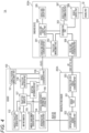
- FIG. 4 is a view illustrating a configuration of a vehicle control system according to a second embodiment of the present invention.
- a vehicle control system 1A illustrated in Fig. 4 includes a server 100, an infrastructure sensor 200A, and an onboard device 300A, and is configured to perform a control for setting, for a target vehicle on which the onboard device 300A is mounted, a traveling trajectory to a designated point and causing the target vehicle to move autonomously, in a similar manner to the vehicle control system 1 of the first embodiment.
- the infrastructure sensor 200A further includes an infrastructure-side vehicle coordination part 203
- the onboard device 300A includes a vehicle-side infrastructure coordination part 309 instead of the map information 306 and is not connected to the onboard sensor 31.
- the vehicle control system 1A of the present embodiment is different from the vehicle control system 1 of the first embodiment. Focusing on these differences, the following will describe the vehicle control system 1A of the present embodiment.
- the infrastructure-side vehicle coordination part 203 has a communication function to communicate with the onboard device 300A.
- the infrastructure-side vehicle coordination part 203 transmits sensing information generated by a sensor part 201 to the onboard device 300A.
- the infrastructure-side vehicle coordination part 203 can communicate with the onboard device 300A via road-vehicle communication, such as the one called Vehicle-to-Infrastructure (V2I) communication.
- road-vehicle communication such as the one called Vehicle-to-Infrastructure (V2I) communication.
- a communication standard such as Dedicated Short Range Communications (DSRC) may be employed.
- the vehicle-side infrastructure coordination part 309 has a communication function to communicate with the infrastructure sensor 200A.
- the vehicle-side infrastructure coordination part 309 is configured to receive the sensing information transmitted from the infrastructure sensor 200A.
- the vehicle-side infrastructure coordination part 309 can communicate with the infrastructure-side vehicle coordination part 203 of the infrastructure sensor 200A via road-vehicle communication, such as the one called V2I.
- the onboard device 300A uses, instead of the map information 306 and the information from the onboard sensor 31, the sensing information received by the vehicle-side infrastructure coordination part 309 from the infrastructure sensor 200A to cause the determination part 303 to make a determination on a motion of the target vehicle and to cause the vehicle control part 308 to perform a control on the target vehicle.
- the determination as to the presence or absence of an obstacle in front of the target vehicle that is moving autonomously along the traveling trajectory is made based on the sensing information received from the infrastructure sensor 200A. Then, if an obstacle is detected, the target vehicle is controlled to apply emergency braking.
- the sensing information may be used for other processes.
- the infrastructure sensor 200A includes the infrastructure-side vehicle coordination part 203 configured to send the sensing information to the onboard device 300A, whereas the onboard device 300A includes the vehicle-side infrastructure coordination part 309 configured to receive the sensing information transmitted from the infrastructure sensor 200A.
- the vehicle control part 308 uses the sensing information received by the vehicle-side infrastructure coordination part 309 to control a motion of the target vehicle that is caused to move autonomously along the traveling trajectory. Consequently, it is possible to cause the target vehicle to move autonomously along the traveling trajectory even if the target vehicle does not have the highly accurate map information 306 and the onboard sensor 31.
- the resetting determination part 110 executes the processes illustrated in Fig. 3 to determine whether to reset the traveling trajectory of the target vehicle.
- the present invention is not limited to such examples.
- at least one of steps S201, S203, and S206 may be omitted, for example.
- a process that is not step S201, S203, or S206 may be added.
Landscapes
- Engineering & Computer Science (AREA)
- Physics & Mathematics (AREA)
- Automation & Control Theory (AREA)
- Radar, Positioning & Navigation (AREA)
- General Physics & Mathematics (AREA)
- Remote Sensing (AREA)
- Transportation (AREA)
- Mechanical Engineering (AREA)
- Mathematical Physics (AREA)
- Aviation & Aerospace Engineering (AREA)
- Human Computer Interaction (AREA)
- Computer Networks & Wireless Communication (AREA)
- Signal Processing (AREA)
- Traffic Control Systems (AREA)
- Navigation (AREA)
- Control Of Driving Devices And Active Controlling Of Vehicle (AREA)
Description
- The present invention relates to a vehicle control system.
- There has been proposed a technique for setting a traveling trajectory from a current position of a vehicle to a designated position and causing the vehicle to move autonomously along the traveling trajectory without driver's driving operation. For example,
JP 2018-531385 A
US 2017/315551 A1 shows a vehicle control system including an automated drive control unit that performs automated driving wherein the automated drive control unit executes a handover where an automated driving mode is switched to a manual driving mode, a calculating unit that calculates an occurrence frequency of the handover or an occurrence probability of the handover on a traveling route that the vehicle will travel. - The determination of the optimal traveling trajectory for the vehicle to perform autonomous movement may be affected not only by the physical characteristics of the vehicle but also by an ambient environment of the vehicle. Therefore, in a case where the ambient environment changes with the lapse of time, even a traveling trajectory determined as optimal once is not always optimal at a timing when the vehicle actually travels. However, according to the technique of
JP 2018-531385 A - The above problem is solved by the subject matter of the appended claims.
- According to the present invention, it is possible to set an optimal traveling trajectory again according to a change in an ambient environment.
-
-
Fig. 1 is a view illustrating a configuration of a vehicle control system according to a first embodiment of the present invention; -
Fig. 2 is a sequence diagram of an autonomous movement control; -
Fig. 3 is a flowchart illustrating a resetting determination process for a traveling trajectory; and -
Fig. 4 is a view illustrating a configuration of a vehicle control system according to a second embodiment of the present invention. -
Fig. 1 is a view illustrating a configuration of a vehicle control system according to a first embodiment of the present invention. Avehicle control system 1 illustrated inFig. 1 includes aserver 100, aninfrastructure sensor 200, and anonboard device 300. Thevehicle control system 1 performs a control to set, for a vehicle on which theonboard device 300 is mounted, a traveling trajectory leading to a designated point and to cause the vehicle to move autonomously. In the description below, the vehicle that is to be controlled by thevehicle control system 1, i.e., the vehicle on which theonboard device 300 is mounted is referred to as a "target vehicle". - The
server 100 is information equipment for setting a traveling trajectory along which the target vehicle is caused to move autonomously and transmitting the traveling trajectory to the target vehicle. Theserver 100 is installed in a predetermined facility, such as an information center. Theserver 100 includes functional blocks including a vehicleposition management part 101, a candidatetrajectory generation part 102,map information 103, aninfrastructure coordination part 104, an ambientenvironment generation part 105, a vehicle characteristicinformation storage part 106, atrajectory simulator 107, atrajectory evaluation part 108, avehicle coordination part 109, and aresetting determination part 110. Theserver 100 has a hardware structure including a CPU, a memory, and a storage (e.g., HDD, SSD), each of which is not illustrated. With use of these pieces of hardware, theserver 100 executes a predetermined program to achieve the functional blocks described above. - The
infrastructure sensor 200 is installed near the traveling trajectory that is to be set by theserver 100. Theinfrastructure sensor 200 detects, at a location outside the target vehicle, an obstacle existing in an area surrounding the traveling trajectory.Fig. 1 shows only oneinfrastructure sensor 200. Alternatively, a plurality ofinfrastructure sensors 200 may be installed near the traveling trajectory. Theinfrastructure sensor 200 includes functional blocks including asensor part 201 and an infrastructure-sideserver coordination part 202. - The
onboard device 300 is installed on the target vehicle. Theonboard device 300 performs a control required to cause the target vehicle to move autonomously to the designated point along the traveling trajectory provided by theserver 100.Fig. 1 shows only oneonboard device 300. Alternatively, two or more vehicles may include their respectiveonboard devices 300, each of which constitutes thevehicle control system 1 in combination with theserver 100 and theinfrastructure sensor 200. Theonboard device 300 includes functional blocks including a vehicle-sideserver coordination part 301, atrajectory management part 302, adetermination part 303, a vehicle-sidedisplay control part 304, a vehicle-side display part 305,map information 306, a vehicleposition determination part 307, and avehicle control part 308. - Next, the following will describe the functional blocks of the
server 100, theinfrastructure sensor 200, and theonboard device 300. - In the
server 100, the vehicleposition management part 101 manages positions of the vehicles on which theonboard devices 300 are mounted. For example, the vehicleposition management part 101 manages the positions of the vehicles by storing and retaining pieces of position information of the vehicles in association with unique vehicles IDs preliminarily assigned to the vehicles. The positions of the vehicles are uprated as appropriate according to pieces of position information supplied from theonboard device 300. - The candidate
trajectory generation part 102 uses themap information 103 to generate a candidate traveling trajectory, which is a candidate of a traveling trajectory along which the target vehicle is caused to move autonomously. For example, the candidatetrajectory generation part 102 obtains information indicating a current position of the target vehicle from theonboard device 300, and generates a plurality of candidate traveling trajectories used to cause the target vehicle to move autonomously from the obtained current position to a designated parking position and to park the target vehicle at the designated parking position. The candidate traveling trajectories may be generated with use of information indicating an ambient environment of the target vehicle generated by the ambientenvironment generation part 105 based on sensing information obtained from theinfrastructure sensor 200 and/or various information (e.g., traffic information, weather information) obtained externally. It should be noted that the candidate traveling trajectories generated by the candidatetrajectory generation part 102 may include a traveling trajectory along which the target vehicle cannot actually travel (e.g., a candidate traveling trajectory including an obstacle in its midway, a traveling trajectory in which the target vehicle cannot be steered). - The
map information 103 is information indicating a map of a region in which the target vehicle moves autonomously. Themap information 103 is stored in a storage, such as HDD or SDD, in theserver 100. For example, themap information 103 includes road map information of various areas in the country, map information of the areas inside car parks, and/or the like. In order to set a traveling trajectory along which the target vehicle can move autonomously and correctly based on themap information 103, themap information 103 is preferably the one that is more precise than map information generally used in conventional navigation devices and/or the like. - The
infrastructure coordination part 104 has a communication function to communicate with theinfrastructure sensor 200. Theinfrastructure coordination part 104 receives information from theinfrastructure sensor 200 and to transmit information to theinfrastructure sensor 200. Theinfrastructure coordination part 104 can communicate with theinfrastructure sensor 200, e.g., via a mobile communication network (4G, 5G) or a fixed line. - The ambient
environment generation part 105 generates information indicating an ambient environment of the target vehicle and the traveling trajectory based on the sensing information transmitted from theinfrastructure sensor 200 and received by theinfrastructure coordination part 104. The information indicating the ambient environment generated by the ambientenvironment generation part 105 can be obtained by performing a predetermined calculating process with use of the sensing information transmitted from theinfrastructure sensor 200, the sensing information being information indicating the positions, sizes, shapes, and/or the like of various obstacles and background objects (e.g., other vehicles, parked vehicles, pedestrians, bicycles, traffic signals, telegraph poles, road signs, street trees, and signboards) existing around the target vehicle and/or the traveling trajectory. The information indicating the ambient environment may be generated by any method, as long as the method can generate ambient environment information that can accurately represent at least an obstacle interfering with the traveling trajectory, if present. - The vehicle characteristic
information storage part 106 stores and retains characteristic information of various vehicles including the target vehicle. The characteristic information is information indicating characteristics of the vehicles related to autonomous movement, and includes information indicating the sizes, weights, yaw inertia moments, distances between axles, gravity center positions, and cornering power, for example. - The
trajectory simulator 107 executes, on each of the candidate traveling trajectories generated by the candidatetrajectory generation part 102, a trajectory simulation involving use of the characteristic information of the target vehicle stored in the vehicle characteristicinformation storage part 106. Thetrajectory simulator 107 performs the trajectory simulation by calculating behaviors of the target vehicle that is moving autonomously along each of the candidate traveling trajectories with use of, e.g., themap information 103 and/or the information indicating the ambient environment generated by the ambientenvironment generation part 105. The trajectory simulation may be performed in consideration of external factors, such as the conditions of a road surface and/or behaviors of an obstacle existing in its surrounding area. - The
trajectory evaluation part 108 determines a traveling trajectory along which the target vehicle is caused to move autonomously, based on the results of the trajectory simulations performed by thetrajectory simulator 107. For example, thetrajectory evaluation part 108 sets evaluation values on the candidate traveling trajectories based on the behaviors of the target vehicle in the candidate traveling trajectories obtained as a result of the trajectory simulations, and determines, as a traveling trajectory of the target vehicle, a candidate traveling trajectory having the lowest evaluation value, i.e., a candidate traveling trajectory that gives the lowest load on the target vehicle. Instead of this, the evaluation may be performed by any method, as long as the method can determine a traveling trajectory from among the plurality of candidate traveling trajectories based on the results of the trajectory simulations. - The
vehicle coordination part 109 has a communication function to communicate with theonboard device 300. Thevehicle coordination part 109 receives the position information of the target vehicle from theonboard device 300, and transmits the information of the traveling trajectory determined by thetrajectory evaluation part 108 to theonboard device 300. Thevehicle coordination part 109 can communicate with theonboard device 300, e.g., via a mobile communication network (4G, 5G). - The resetting
determination part 110 determines whether to reset the traveling trajectory determined by thetrajectory evaluation part 108, based on the current situation of the target vehicle. If the resettingdetermination part 110 determines to reset the traveling trajectory, theserver 100 executes, via thetrajectory simulator 107, trajectory simulations again. Then, theserver 100 determines, via thetrajectory evaluation part 108, a new traveling trajectory of the target vehicle based on the result of the trajectory simulation. Then, thevehicle coordination part 109 transmits the information of the new traveling trajectory thus determined to theonboard device 300. The method how the resettingdetermination part 110 determines whether to reset the traveling trajectory will be described in detail later. - In the
infrastructure sensor 200, thesensor part 201 is constituted by various sensors, such as a camera, a radar, light detection and ranging (LiDAR). Thesensor part 201 generates sensing information corresponding to a predetermined sensing range of the sensors based on the position where theinfrastructure sensor 200 is installed. The sensing information includes information of an obstacle existing in the sensing range. - The infrastructure-side
server coordination part 202 has a communication function to communicate with theserver 100. The infrastructure-sideserver coordination part 202 transmits the sensing information generated by thesensor part 201 to theserver 100. The infrastructure-sideserver coordination part 202 can communicate with theinfrastructure coordination part 104 of theserver 100, e.g., via a mobile communication network (4G, 5G) or a fixed line. - In the
onboard device 300, the vehicle-sideserver coordination part 301 has a communication function to communicate with theserver 100. The vehicle-sideserver coordination part 301 transmits the position information of the target vehicle to theserver 100, and receives the information on the traveling trajectory transmitted from theserver 100. The vehicle-sideserver coordination part 301 can communicate with thevehicle coordination part 109 of theserver 100, e.g., via a mobile communication network (4G, 5G). - The
trajectory management part 302 manages the traveling trajectory along which the target vehicle moves autonomously according to the information on the traveling trajectory transmitted from theserver 100. If the resettingdetermination part 110 in theserver 100 determines to reset the traveling trajectory in the above-described manner and accordingly a new traveling trajectory determined is transmitted from theserver 100 and received by the vehicle-sideserver coordination part 301, thetrajectory management part 302 discards the existing traveling trajectory and sets the new traveling trajectory according to the received information. - The
determination part 303 determines a motion required to cause the target vehicle to move autonomously along the traveling trajectory managed by thetrajectory management part 302, based on themap information 306 and information indicating the current position of the target vehicle determined by the vehicleposition determination part 307. For example, thedetermination part 303 determines the speed, the acceleration, and the steering amount of the target vehicle based on the length and/or the curvature of the traveling trajectory. The determination may be made further based on information on an area surrounding the target vehicle obtained from anonboard sensor 31. For example, if an obstacle existing in front of the target vehicle is detected, a determination may be made to apply emergency braking. - The vehicle-side
display control part 304 generates a screen to be displayed on the vehicle-side display part 305, based on themap information 306, the traveling trajectory managed by thetrajectory management part 302, and the determination result of thedetermination part 303. The vehicle-side display part 305 is made of a liquid crystal display, for example. The vehicle-side display part 305 displays the screen generated by the vehicle-sidedisplay control part 304 to give a notification to a passenger on the target vehicle. With this configuration, for example, the vehicle-side display part 305 displays a screen indicating a traveling trajectory on a map or a screen notifying the passenger on the target vehicle of the fact that the traveling trajectory has been reset or the fact that an obstacle has been detected, if this happens. Alternatively, a sound from a speaker (not illustrated) may be used in combination with or instead of the screen on the vehicle-side display part 305 to give a notification to the passenger. - Similarly to the
map information 103 of theserver 100, themap information 306 is information indicating a map of a region where the target vehicle moves autonomously, and is stored in a not-illustrated storage (e.g., HDD, SDD) in theonboard device 300. Themap information 306 is used by thedetermination part 303 to make a determination on a motion of the target vehicle and/or by the vehicle-sidedisplay control part 304 to generate a map screen, for example. Similarly to themap information 103 of theserver 100, themap information 306 is preferably the one that is more precise than a generally-used conventional map. - The vehicle
position determination part 307 determines the position of the target vehicle based on a GPS signal received by a GPS sensor (not illustrated) and/or information (e.g., a speed, an acceleration, a steering amount) about an operating state of the target vehicle detected by theonboard sensor 31. Themap information 306 may be used to perform a well-known map matching process to position the target vehicle on a road. The position information of the target vehicle determined by the vehicleposition determination part 307 is transmitted to theserver 100 by the vehicle-sideserver coordination part 301, and is used by the vehicleposition management part 101 to manage the position of the target vehicle. - The
vehicle control part 308 performs a control on the target vehicle based on the result of the determination on the motion of the target vehicle which determination has been made by thedetermination part 303. Thevehicle control part 308 is connected to a drivingpart 32 of the target vehicle. Thevehicle control part 308 controls the drivingpart 32 to execute an acceleration operation, a braking operation, a steering operation, or the like of the target vehicle. In this manner, thevehicle control part 308 controls the operating state of the target vehicle according to the determination result of thedetermination part 303. - Next, with reference to
Figs. 2 and3 , the following will describe specific examples of an autonomous movement control performed by thevehicle control system 1 according to the present embodiment. -
Fig. 2 is a sequence diagram of the autonomous movement control performed by thevehicle control system 1. - In step S101, the
onboard device 300 transmits, via the vehicle-sideserver coordination part 301, a request on a traveling trajectory to theserver 100. Theonboard device 300 transmits the request on the traveling trajectory to theserver 100 by executing step S101, if the passenger on the target vehicle gives an instruction to execute automatic parking or automatic driving or a determination or if a new traveling trajectory is determined to be necessary during automatic driving, for example. The request on the traveling trajectory includes information indicating a target point (e.g., a parking position, a point where a control for automatic driving is performed), which is a destination of the autonomous movement of the target vehicle. Theserver 100 receives, via thevehicle coordination part 109, the request on the traveling trajectory transmitted from theonboard device 300. - In step S102, the
infrastructure sensor 200 transmits, via the infrastructure-sideserver coordination part 202, the sensing information generated by thesensor part 201 to theserver 100. Theserver 100 receives, via theinfrastructure coordination part 104, the sensing information transmitted from theinfrastructure sensor 200. - In step S103, the
server 100 generates, via the ambientenvironment generation part 105, information indicating an ambient environment of the target vehicle, based on the sensing information received from theinfrastructure sensor 200 in step S102. - In step S104, the
server 100 generates, via the candidatetrajectory generation part 102, candidate traveling trajectories from which the traveling trajectory is obtained. In this process, the candidatetrajectory generation part 102 obtains the information indicating the current position of the target vehicle from the vehicleposition management part 101, and generates a plurality of candidate traveling trajectories located between the current position and the target point included in the request received in step S101. - In step S105, the
server 100 obtains, via thetrajectory simulator 107, characteristic information of the target vehicle from the vehicle characteristicinformation storage part 106. In this process, thetrajectory simulator 107 obtains, as the characteristic information of the target vehicle, a piece of characteristic information of a vehicle including theonboard device 300 that has transmitted the request on the traveling trajectory in step S101, from among the pieces of characteristic information of the vehicles stored in the vehicle characteristicinformation storage part 106. - In step S106, the
server 100 executes, via thetrajectory simulator 107, a trajectory simulation on each of the candidate traveling trajectories generated in step S104. In this process, thetrajectory simulator 107 executes a trajectory simulation of calculating behaviors of the target vehicle that is moving autonomously along each of the candidate traveling trajectories, based on the information indicating the ambient environment generated in step S103 and the characteristic information of the target vehicle obtained in step S105. - In step S107, the
server 100 performs, via thetrajectory evaluation part 108, trajectory evaluations on the results of the trajectory simulations executed in step S106. In this process, thetrajectory evaluation part 108 sets evaluation values on the candidate traveling trajectories based on the behaviors of the target vehicle in the candidate traveling trajectories obtained as a result of the trajectory simulations in the above-described manner, for example. Then, thetrajectory evaluation part 108 determines, as the traveling trajectory of the target vehicle, a candidate traveling trajectory whose evaluation value is lower than those of any other candidate traveling trajectories. - In step S108, the
server 100 transmits, via thevehicle coordination part 109, the information of the traveling trajectory determined in step S107 to theonboard device 300. Theonboard device 300 receives, via the vehicle-sideserver coordination part 301, the traveling trajectory information transmitted from theserver 100. - In step S109, the
onboard device 300 executes a control for causing the target vehicle to move autonomously following the traveling trajectory, based on the traveling trajectory information received from theserver 100 in step S108. In this process, theonboard device 300 causes thetrajectory management part 302 to store and retain the received traveling trajectory information, and causes thedetermination part 303 and thevehicle control part 308 to control the operating state of the target vehicle. In this manner, theonboard device 300 causes the target vehicle to move autonomously following the traveling trajectory. - In step S110, the
onboard device 300 determines, via thedetermination part 303, whether to give up the autonomous movement of the target vehicle. In this process, during the control in step S109, theonboard device 300 determines whether or not the target vehicle cannot move autonomously along the traveling trajectory any more. If theonboard device 300 determines that such a situation occurs, theonboard device 300 determines to give up the autonomous movement of the target vehicle. This situation may be, for example, a situation where theonboard sensor 31 detects an obstacle on the traveling trajectory, a situation where the target vehicle is away from the traveling trajectory by a predetermined distance or more, or a situation where it is determined that the target vehicle cannot be steered. In an alternative configuration, the passenger on the target vehicle may perform a predetermined operation with respect to theonboard device 300 to choose giving up. If any of these situations occurs, theonboard device 300 determines to give up the autonomous movement of the target vehicle, and stops the control performed in step S109. Then, the process advances to step Sill. Meanwhile, if none of these situations occurs, theonboard device 300 determines to continue the control performed in step S109, rather than giving up. Then, the process advances to step S112. - In step Sill, the
onboard device 300 transmits, via the vehicle-sideserver coordination part 301, a predetermined giving-up notification to theserver 100. Theserver 100 receives, via thevehicle coordination part 109, the giving-up notification transmitted from theonboard device 300. - In step S112, the
onboard device 300 determines, via thedetermination part 303, whether or not the target vehicle has arrived at the terminal point of the traveling trajectory, i.e., the target point of the autonomous movement, based on the information indicating the current position of the target vehicle determined by the vehicleposition determination part 307. If the target vehicle has not arrived at the terminal point of the traveling trajectory, the process returns to step S109 to continue the control of the target vehicle. Meanwhile, if the target vehicle has arrived at the terminal point of the traveling trajectory, the sequence illustrated inFig. 2 is ended. - In step S113, the
server 100 determines, via the resettingdetermination part 110, whether to reset the traveling trajectory of the target vehicle. If the resettingdetermination part 110 determines not to reset the traveling trajectory, the process stays at step S113. Meanwhile, if the resettingdetermination part 110 determines to reset the traveling trajectory, the process returns to step S102 to reset the traveling trajectory. That is, based on the sensing information received from theinfrastructure sensor 200, theserver 100 generates, via the ambientenvironment generation part 105, information indicating an ambient environment of the target vehicle and the traveling trajectory corresponding to the current situation (step S103), and generates a plurality of candidate traveling trajectories again (step S104). Then, theserver 100 executes trajectory simulations again based on the generated ambient environment information and the characteristic information of the target vehicle (step S106), and determines a new traveling trajectory of the target vehicle based on the results of the trajectory simulations (step S107). The information of the new traveling trajectory thus determined is transmitted from theserver 100 to theonboard device 300 in step S108. Then, thetrajectory management part 302 of theonboard device 300 updates the traveling trajectory of the target vehicle. The method how the resettingdetermination part 110 determines whether to reset the traveling trajectory will be described below with reference to the flowchart illustrated inFig. 3 . -
Fig. 3 is a flowchart illustrating a resetting determination process for a traveling trajectory executed in step S113 inFig. 2 . - In step S201, the resetting
determination part 110 determines whether or not thevehicle coordination part 109 has received the giving-up notification transmitted from theonboard device 300 in step Sill inFig. 2 . If thevehicle coordination part 109 has received the giving-up notification, the process advances to step S208. Meanwhile, if thevehicle coordination part 109 has not received the giving-up notification, the process advances to step S202. - In step S202, the resetting
determination part 110 obtains the information indicating the ambient environment generated by the ambientenvironment generation part 105. In this process, the resettingdetermination part 110 obtains the information indicating the ambient environment of the traveling trajectory generated by the ambientenvironment generation part 105 based on the sensing information periodically transmitted from theinfrastructure sensor 200. The information indicating the ambient environment of the traveling trajectory includes an obstacle that exists in an area surrounding the traveling trajectory but cannot be detected by the target vehicle, for example. - In step S203, the resetting
determination part 110 determines the presence or absence of an obstacle interfering with the traveling trajectory based on the information indicating the ambient environment of the traveling trajectory obtained in step S202. In this process, the resettingdetermination part 110 determines, as an obstacle interfering with the traveling trajectory, an obstacle that exists near the traveling trajectory and that may potentially come into contact with the target vehicle, for example. The determination of whether or not the obstacle interferes with the traveling trajectory may be made in consideration of the characteristic information of the target vehicle stored in the vehicle characteristicinformation storage part 106, a motion of the obstacle in the ambient environment of the traveling trajectory, and/or the like. If the resettingdetermination part 110 determines that the obstacle interfering with the traveling trajectory exists, the process advances to step S208. Meanwhile, if the resettingdetermination part 110 determines that the obstacle interfering with the traveling trajectory does not exist, the process advances to step S204. - In step S204, the resetting
determination part 110 obtains evaluation results of the trajectory simulations given by thetrajectory evaluation part 108 in step S107 with respect to the candidate traveling trajectories generated by the candidatetrajectory generation part 102 in step S104 inFig. 2 . - In step S205, the resetting
determination part 110 sets a resetting determination region used for resetting determination on the traveling trajectory, based on the evaluation results of the candidate traveling trajectories obtained in step S204. In this process, for example, from among the plurality of candidate traveling trajectories whose evaluation results have been obtained, the resettingdetermination part 110 identifies paired left and right candidate traveling trajectories separated the farthest away from each other laterally across the current traveling trajectory, and sets, as a resetting determination region, a region defined by the paired candidate traveling trajectories. If the candidate traveling trajectories include a candidate traveling trajectory whose evaluation value is equal to or higher than a predetermined threshold value, it is preferable that such a candidate traveling trajectory be determined as the one along which the target vehicle cannot travel and be excluded from the objects that may be used to define the resetting determination region. With this configuration, the resettingdetermination part 110 can set the resetting determination region based on the position of the certain candidate traveling trajectory having been selected from among the plurality of candidate traveling trajectories, the certain candidate traveling trajectory being determined by thetrajectory evaluation part 108 as the one along which the target vehicle can travel, the certain candidate traveling trajectory being separated farther away from the traveling trajectory than any other candidate traveling trajectories. - In step S206, the resetting
determination part 110 determines whether or not the position of the target vehicle deviates from the resetting determination region set in step S205. If the position of the target vehicle stays within the resetting determination region, the process advances to step S207. Meanwhile, if the position of the target vehicle deviates from the resetting determination region, the process advances to step S208. - In step S207, the resetting
determination part 110 determines it unnecessary to reset the traveling trajectory. In this case, in step S113 inFig. 2 , it is determined not to reset the traveling trajectory. - In step S208, the resetting
determination part 110 determines it necessary to reset the traveling trajectory. In this case, in step S113 inFig. 2 , it is determined to reset the traveling trajectory. - If the determination result as to whether to reset the traveling trajectory of the target vehicle is obtained as a result of execution of step S207 or S208, the resetting
determination part 110 ends the resetting determination process for the traveling trajectory, which is illustrated in the flowchart inFig. 3 . - The above-described first embodiment of the present invention brings about the following effects.
-
- (1) The
vehicle control system 1 includes: theserver 100 configured to set a traveling trajectory along which the target vehicle is caused to move autonomously; theonboard device 300 mounted on the target vehicle; and theinfrastructure sensor 200 capable of generating sensing information about an area surrounding the traveling trajectory. Theserver 100 includes: the candidatetrajectory generation part 102 configured to generate a candidate traveling trajectory of the target vehicle; the vehicle characteristicinformation storage part 106 configured to store characteristic information of the target vehicle; thetrajectory simulator 107 configured to execute, on the candidate traveling trajectory generated by the candidatetrajectory generation part 102, a trajectory simulation involving use of the characteristic information of the target vehicle; thetrajectory evaluation part 108 configured to determine the traveling trajectory based on a result of the trajectory simulation performed by thetrajectory simulator 107; thevehicle coordination part 109 having a communication function to communicate with theonboard device 300 and being configured to transmit information of the traveling trajectory determined by thetrajectory evaluation part 108 to theonboard device 300; theinfrastructure coordination part 104 having a communication function to communicate with theinfrastructure sensor 200 and being configured to obtain the sensing information from theinfrastructure sensor 200; the ambientenvironment generation part 105 configured to generate information indicating an ambient environment of the traveling trajectory, based on the sensing information obtained by theinfrastructure coordination part 104; and the resettingdetermination part 110 configured to determine whether to reset the traveling trajectory. Theinfrastructure sensor 200 includes: thesensor part 201 configured to generate the sensing information; and the infrastructure-sideserver coordination part 202 configured to transmit the sensing information to theserver 100. Theonboard device 300 includes: the vehicle-sideserver coordination part 301 configured to obtain the information of the traveling trajectory from theserver 100; and thevehicle control part 308 configured to cause the target vehicle to move autonomously along the traveling trajectory based on the information of the traveling trajectory obtained by the vehicle-sideserver coordination part 301. Thetrajectory simulator 107 executes a trajectory simulation again with use of the information indicating the ambient environment generated by the ambient environment generation part 105 (step S106), if the resettingdetermination part 110 determines to reset the traveling trajectory (Yes in step S113). Thetrajectory evaluation part 108 determines a new traveling trajectory of the target vehicle based on a result of the trajectory simulation executed by thetrajectory simulator 107 again (step S107). Thevehicle coordination part 109 transmits, to theonboard device 300, information of the new traveling trajectory determined by the trajectory evaluation part 108 (step S108). Thanks to this configuration, it is possible to set a suitable traveling trajectory according to changes in the ambient environment. - (2) The
onboard device 300 transmits predetermined information as a giving-up notification to theserver 100, if the autonomous movement along the traveling trajectory is determined to be impossible (step S111). The resettingdetermination part 110 is configured to determine to reset the traveling trajectory (step S208), if the giving-up notification is transmitted from the onboard device 300 (Yes in step S201). Thanks to this configuration, it is possible to reliably determine to reset the traveling trajectory, if it becomes impossible for the target vehicle to move autonomously following the traveling trajectory any more. - (3) The resetting
determination part 110 determines the presence or absence of an obstacle interfering with the traveling trajectory based on the sensing information (step S203), and determines whether to reset the traveling trajectory based on a result of the determination (step S207, S208). Thanks to this configuration, it is possible to reliably determine to reset the traveling trajectory, if theinfrastructure sensor 200 detects an obstacle interfering with the traveling trajectory. - (4) The resetting
determination part 110 sets, as a resetting determination region, a region of a predetermined range including the traveling trajectory (step S205), and determines to reset the traveling trajectory (step S208) if the position of the target vehicle deviates from the resetting determination region (Yes in step S206). Thanks to this configuration, it is possible to reliably determine to reset the traveling trajectory, if the target vehicle is greatly deviated from the traveling trajectory and cannot come back again to the traveling trajectory. - (5) The candidate
trajectory generation part 102 is configured to generate a plurality of candidate traveling trajectories. The resettingdetermination part 110 sets the resetting determination region based on the position of a certain candidate traveling trajectory having been selected from among the plurality of candidate traveling trajectories, the certain candidate traveling trajectory being determined by thetrajectory evaluation part 108 as the one along which the target vehicle can travel, the certain candidate traveling trajectory being separated farther away from the traveling trajectory than any other candidate traveling trajectories. Thanks to this configuration, it is possible to easily and appropriately set the resetting determination region with use of the results of the evaluations on the candidate traveling trajectories having been made when thetrajectory evaluation part 108 determines the traveling trajectory. -
Fig. 4 is a view illustrating a configuration of a vehicle control system according to a second embodiment of the present invention. Avehicle control system 1A illustrated inFig. 4 includes aserver 100, aninfrastructure sensor 200A, and anonboard device 300A, and is configured to perform a control for setting, for a target vehicle on which theonboard device 300A is mounted, a traveling trajectory to a designated point and causing the target vehicle to move autonomously, in a similar manner to thevehicle control system 1 of the first embodiment. In thevehicle control system 1A of the present embodiment, theinfrastructure sensor 200A further includes an infrastructure-sidevehicle coordination part 203, and theonboard device 300A includes a vehicle-sideinfrastructure coordination part 309 instead of themap information 306 and is not connected to theonboard sensor 31. In these points, thevehicle control system 1A of the present embodiment is different from thevehicle control system 1 of the first embodiment. Focusing on these differences, the following will describe thevehicle control system 1A of the present embodiment. - The infrastructure-side
vehicle coordination part 203 has a communication function to communicate with theonboard device 300A. The infrastructure-sidevehicle coordination part 203 transmits sensing information generated by asensor part 201 to theonboard device 300A. The infrastructure-sidevehicle coordination part 203 can communicate with theonboard device 300A via road-vehicle communication, such as the one called Vehicle-to-Infrastructure (V2I) communication. As the road-vehicle communication, a communication standard such as Dedicated Short Range Communications (DSRC) may be employed. - The vehicle-side
infrastructure coordination part 309 has a communication function to communicate with theinfrastructure sensor 200A. The vehicle-sideinfrastructure coordination part 309 is configured to receive the sensing information transmitted from theinfrastructure sensor 200A. The vehicle-sideinfrastructure coordination part 309 can communicate with the infrastructure-sidevehicle coordination part 203 of theinfrastructure sensor 200A via road-vehicle communication, such as the one called V2I. - In the present embodiment, the
onboard device 300A uses, instead of themap information 306 and the information from theonboard sensor 31, the sensing information received by the vehicle-sideinfrastructure coordination part 309 from theinfrastructure sensor 200A to cause thedetermination part 303 to make a determination on a motion of the target vehicle and to cause thevehicle control part 308 to perform a control on the target vehicle. For example, the determination as to the presence or absence of an obstacle in front of the target vehicle that is moving autonomously along the traveling trajectory is made based on the sensing information received from theinfrastructure sensor 200A. Then, if an obstacle is detected, the target vehicle is controlled to apply emergency braking. It should be noted that the sensing information may be used for other processes. - According to the above-described second embodiment of the present invention, the
infrastructure sensor 200A includes the infrastructure-sidevehicle coordination part 203 configured to send the sensing information to theonboard device 300A, whereas theonboard device 300A includes the vehicle-sideinfrastructure coordination part 309 configured to receive the sensing information transmitted from theinfrastructure sensor 200A. Thevehicle control part 308 uses the sensing information received by the vehicle-sideinfrastructure coordination part 309 to control a motion of the target vehicle that is caused to move autonomously along the traveling trajectory. Consequently, it is possible to cause the target vehicle to move autonomously along the traveling trajectory even if the target vehicle does not have the highlyaccurate map information 306 and theonboard sensor 31. - In the examples described in the above-described embodiments of the present invention, the resetting
determination part 110 executes the processes illustrated inFig. 3 to determine whether to reset the traveling trajectory of the target vehicle. However, the present invention is not limited to such examples. Alternatively, at least one of steps S201, S203, and S206 may be omitted, for example. Further alternatively, a process that is not step S201, S203, or S206 may be added. There may be a case where it becomes difficult for the target vehicle to move autonomously due to changes in the ambient environment and accordingly it becomes necessary to reset the traveling trajectory. In such a case, it is possible to determine whether to reset the traveling trajectory of the target vehicle by any method, as long as the method can determine occurrence of such a situation in a reliable manner.
Claims (4)
- A vehicle control system comprising:a server (100) configured to set a traveling trajectory along which a vehicle is caused to move autonomously;an onboard device (300) mountable on the vehicle; andan infrastructure sensor (200) capable of generating sensing information about an area surrounding the traveling trajectory, whereinthe server (100) includes:a candidate trajectory generation part (102) configured to generate a candidate traveling trajectory of the vehicle,a vehicle characteristic information storage part (106) configured to store characteristic information of the vehicle;a trajectory simulator (107) configured to execute, on the candidate traveling trajectory generated by the candidate trajectory generation part, a trajectory simulation involving use of the characteristic information,a trajectory evaluation part (108) configured to determine a traveling trajectory based on a result of the trajectory simulation performed by the trajectory simulator,a vehicle coordination part (109) having a communication function to communicate with the onboard device and being configured to transmit information of the traveling trajectory determined by the trajectory evaluation part to the onboard device,an infrastructure coordination part (104) having a communication function to communicate with the infrastructure sensor and being configured to obtain the sensing information from the infrastructure sensor,an ambient environment generation part (105) configured to generate information indicating an ambient environment of the traveling trajectory, based on the sensing information obtained by the infrastructure coordination part, anda resetting determination part (110) configured to determine whether to reset the traveling trajectory,the infrastructure sensor (200) includesa sensor part (201) configured to generate the sensing information, andan infrastructure-side server coordination part (202) configured to transmit the sensing information to the server,the onboard device (300) includesa vehicle-side server coordination part (301) configured to obtain information of the traveling trajectory from the server, anda vehicle control part (308) configured to cause the vehicle to move autonomously along the traveling trajectory based on the information of the traveling trajectory obtained by the vehicle-side server coordination part,the trajectory simulator (107) is configured to execute a trajectory simulation again with use of the information indicating the ambient environment generated by the ambient environment generation part, in a case where the resetting determination part determines to reset the traveling trajectory,the trajectory evaluation part (108) is configured to determine a new traveling trajectory of the vehicle based on a result of the trajectory simulation performed again by the trajectory simulator, andthe vehicle coordination part (109) is configured to transmit, to the onboard device, information of the new traveling trajectory determined by the trajectory evaluation part, whereinthe infrastructure sensor (200) includes an infrastructure-side vehicle coordination part (202) configured to transmit the sensing information to the onboard device, whereinthe infrastructure sensor (200) is at a location outside the vehicle and is installed near the traveling trajectory that is to be set by the server (100), whereinthe onboard device (300) includes a vehicle-side infrastructure coordination part (301) configured to receive the sensing information transmitted from the infrastructure sensor, andthe vehicle control part (308) is configured to use the sensing information received by the vehicle-side infrastructure coordination part to control a motion of the vehicle that is caused to move autonomously along the traveling trajectory whereinthe resetting determination part (110) is configured to determine presence or absence of an obstacle interfering with the traveling trajectory based on the sensing information, and is configured to determine whether to reset the traveling trajectory based on a result of the determination.
- The vehicle control system according to claim 1, whereinthe onboard device (300) is configured to transmit predetermined information to the server, in a case where the autonomous movement along the traveling trajectory is determined to be impossible, andthe resetting determination part (110) is configured to determine to reset the traveling trajectory, in a case where the predetermined information is transmitted from the onboard device (300).
- The vehicle control system according to claim 1, wherein
the resetting determination part (110) is configured to set a region of a predetermined range including the traveling trajectory, and to determine to reset the traveling trajectory in a case where a position of the vehicle deviates from the region. - The vehicle control system according to claim 3, whereinthe candidate trajectory generation part (102) is configured to generate a plurality of candidate traveling trajectories, andthe resetting determination part (110) is configured to set the region based on a position of a certain candidate traveling trajectory having been selected from among the plurality of candidate traveling trajectories, the certain candidate traveling trajectory being determined by the trajectory evaluation part as one along which the vehicle is capable of traveling, the certain candidate traveling trajectory being separated farther away from the traveling trajectory than any other candidate traveling trajectories.
Applications Claiming Priority (1)
| Application Number | Priority Date | Filing Date | Title |
|---|---|---|---|
| JP2019036565A JP7155043B2 (en) | 2019-02-28 | 2019-02-28 | Server, vehicle control system |
Publications (2)
| Publication Number | Publication Date |
|---|---|
| EP3702867A1 EP3702867A1 (en) | 2020-09-02 |
| EP3702867B1 true EP3702867B1 (en) | 2024-05-01 |
Family
ID=69742748
Family Applications (1)
| Application Number | Title | Priority Date | Filing Date |
|---|---|---|---|
| EP20159768.9A Active EP3702867B1 (en) | 2019-02-28 | 2020-02-27 | Server and vehicle control system |
Country Status (4)
| Country | Link |
|---|---|
| US (1) | US11292491B2 (en) |
| EP (1) | EP3702867B1 (en) |
| JP (1) | JP7155043B2 (en) |
| CN (1) | CN111619577B (en) |
Families Citing this family (8)
| Publication number | Priority date | Publication date | Assignee | Title |
|---|---|---|---|---|
| US12130621B2 (en) * | 2020-04-17 | 2024-10-29 | Zoox, Inc. | Collaborative vehicle guidance |
| DE112021006820T5 (en) * | 2021-01-15 | 2023-11-09 | Mitsubishi Electric Corporation | REMOTE CONTROL DEVICE |
| JP2023016267A (en) * | 2021-07-21 | 2023-02-02 | 株式会社日立製作所 | Maintenance support system and maintenance support device |
| CN115935573A (en) * | 2021-08-09 | 2023-04-07 | 北京图森智途科技有限公司 | Simulation method for self-driving vehicle and method of controlling self-driving vehicle |
| CN117980846A (en) * | 2021-09-17 | 2024-05-03 | 索尼集团公司 | Mobile control system, mobile control method, mobile control device and information processing device |
| JP7851524B2 (en) * | 2022-02-14 | 2026-04-27 | メイ モビリティー,インコーポレイテッド | Method and system for conditional operation of autonomous agents |
| US20250076874A1 (en) * | 2023-08-31 | 2025-03-06 | Nissan North America, Inc. | Safeguarded Tele-Operation for Autonomous Driving |
| EP4546002A1 (en) * | 2023-10-25 | 2025-04-30 | embotech AG | Control system for steering automated vehicles using heterogeneous redundancy checks |
Family Cites Families (18)
| Publication number | Priority date | Publication date | Assignee | Title |
|---|---|---|---|---|
| JP2002240661A (en) | 2001-02-19 | 2002-08-28 | Nissan Motor Co Ltd | Parking assistance device |
| JP3458156B2 (en) | 2001-03-08 | 2003-10-20 | 国土交通省国土技術政策総合研究所長 | Road-vehicle communication monitoring system |
| JP4403759B2 (en) * | 2003-09-02 | 2010-01-27 | カシオ計算機株式会社 | Navigation device, navigation system, and program |
| GB2412281B (en) * | 2004-03-15 | 2006-12-13 | Tomtom Bv | Navigation device displaying dynamic travel information |
| US20070088469A1 (en) * | 2005-10-04 | 2007-04-19 | Oshkosh Truck Corporation | Vehicle control system and method |
| US11186174B2 (en) * | 2005-11-17 | 2021-11-30 | Invently Automotive Inc. | Vehicle power management system |
| KR101906952B1 (en) | 2013-11-08 | 2018-10-11 | 한화지상방산 주식회사 | Method for generating optimized parking path of manless driving vehicle, and manless driving vehicle adopting the method |
| US9650042B2 (en) * | 2014-09-11 | 2017-05-16 | Cummins Inc. | Systems and methods for route planning |
| JP6354561B2 (en) * | 2014-12-15 | 2018-07-11 | 株式会社デンソー | Orbit determination method, orbit setting device, automatic driving system |
| CN108137045B (en) * | 2015-10-16 | 2021-07-06 | 日立汽车系统株式会社 | Vehicle control system, vehicle control device |
| US9632502B1 (en) * | 2015-11-04 | 2017-04-25 | Zoox, Inc. | Machine-learning systems and techniques to optimize teleoperation and/or planner decisions |
| WO2017111127A1 (en) | 2015-12-23 | 2017-06-29 | 京セラ株式会社 | Server device, vehicle control device, and communication device |
| JP6464500B2 (en) | 2016-03-11 | 2019-02-06 | パナソニックIpマネジメント株式会社 | Automatic vehicle allocation system and server device |
| US20190009819A1 (en) | 2016-03-15 | 2019-01-10 | Honda Motor Co., Ltd. | Vehicle control system, vehicle control method and vehicle control program |
| US9645577B1 (en) * | 2016-03-23 | 2017-05-09 | nuTonomy Inc. | Facilitating vehicle driving and self-driving |
| JP6355111B2 (en) * | 2016-04-28 | 2018-07-11 | 本田技研工業株式会社 | Vehicle control system |
| US10162354B2 (en) | 2016-07-21 | 2018-12-25 | Baidu Usa Llc | Controlling error corrected planning methods for operating autonomous vehicles |
| US11287270B2 (en) * | 2018-12-26 | 2022-03-29 | Beijing Voyager Technology Co., Ltd. | Systems and methods for safe route planning for a vehicle |
-
2019
- 2019-02-28 JP JP2019036565A patent/JP7155043B2/en active Active
-
2020
- 2020-02-24 US US16/798,804 patent/US11292491B2/en active Active
- 2020-02-24 CN CN202010111096.4A patent/CN111619577B/en active Active
- 2020-02-27 EP EP20159768.9A patent/EP3702867B1/en active Active
Also Published As
| Publication number | Publication date |
|---|---|
| JP2020140534A (en) | 2020-09-03 |
| JP7155043B2 (en) | 2022-10-18 |
| US20200276984A1 (en) | 2020-09-03 |
| CN111619577A (en) | 2020-09-04 |
| CN111619577B (en) | 2023-05-23 |
| US11292491B2 (en) | 2022-04-05 |
| EP3702867A1 (en) | 2020-09-02 |
Similar Documents
| Publication | Publication Date | Title |
|---|---|---|
| EP3702867B1 (en) | Server and vehicle control system | |
| CN112368662B (en) | Directional adjustment actions for autonomous vehicle operation management | |
| US11027751B2 (en) | Reinforcement and model learning for vehicle operation | |
| US10982961B2 (en) | Vehicle control system and vehicle control device | |
| EP3580621B1 (en) | Autonomous vehicle operational management | |
| EP3580084B1 (en) | Autonomous vehicle operational management including operating a partially observable markov decision process model instance | |
| EP3717324B1 (en) | Autonomous vehicle operational management scenarios | |
| EP3580620B1 (en) | Autonomous vehicle operational management control | |
| US8140266B2 (en) | Vehicle positioning information updating system | |
| US11921506B2 (en) | Belief state determination for real-time decision-making | |
| US10821976B2 (en) | Navigation system with dynamic speed setting mechanism and method of operation thereof | |
| US20200279481A1 (en) | Server and Vehicle Assistance System | |
| US20180056998A1 (en) | System and Method for Multi-Vehicle Path Planning Technical Field | |
| JP2021026387A (en) | Vehicle traveling control device | |
| JP2019182093A (en) | Behavior prediction device | |
| WO2020116264A1 (en) | Vehicle travel assistance method, vehicle travel assistance device and autonomous driving system | |
| EP4083957B1 (en) | Navigation system with traffic state detection mechanism and method of operation thereof | |
| WO2019089015A1 (en) | Autonomous vehicle operation with explicit occlusion reasoning | |
| US11878695B2 (en) | Surface guided vehicle behavior | |
| US20200139981A1 (en) | Inter-Vehicle Sensor Validation using Senso-Fusion Network | |
| CN114620035A (en) | Wrong-way driving detection and collision mitigation | |
| CN110441806A (en) | Satellite-based method for vehicle location determination via motion and position sensors | |
| US12602996B2 (en) | Autonomous vehicle traffic control at hubs | |
| US20230159026A1 (en) | Predicting Motion of Hypothetical Agents | |
| US20250172399A1 (en) | Method for predicting the availability of a feature-based localization of a vehicle, and method for controlling a vehicle |
Legal Events
| Date | Code | Title | Description |
|---|---|---|---|
| PUAI | Public reference made under article 153(3) epc to a published international application that has entered the european phase |
Free format text: ORIGINAL CODE: 0009012 |
|
| STAA | Information on the status of an ep patent application or granted ep patent |
Free format text: STATUS: REQUEST FOR EXAMINATION WAS MADE |
|
| 17P | Request for examination filed |
Effective date: 20200331 |
|
| AK | Designated contracting states |
Kind code of ref document: A1 Designated state(s): AL AT BE BG CH CY CZ DE DK EE ES FI FR GB GR HR HU IE IS IT LI LT LU LV MC MK MT NL NO PL PT RO RS SE SI SK SM TR |
|
| AX | Request for extension of the european patent |
Extension state: BA ME |
|
| STAA | Information on the status of an ep patent application or granted ep patent |
Free format text: STATUS: EXAMINATION IS IN PROGRESS |
|
| 17Q | First examination report despatched |
Effective date: 20210708 |
|
| GRAP | Despatch of communication of intention to grant a patent |
Free format text: ORIGINAL CODE: EPIDOSNIGR1 |
|
| STAA | Information on the status of an ep patent application or granted ep patent |
Free format text: STATUS: GRANT OF PATENT IS INTENDED |
|
| INTG | Intention to grant announced |
Effective date: 20231121 |
|
| GRAS | Grant fee paid |
Free format text: ORIGINAL CODE: EPIDOSNIGR3 |
|
| GRAA | (expected) grant |
Free format text: ORIGINAL CODE: 0009210 |
|
| STAA | Information on the status of an ep patent application or granted ep patent |
Free format text: STATUS: THE PATENT HAS BEEN GRANTED |
|
| AK | Designated contracting states |
Kind code of ref document: B1 Designated state(s): AL AT BE BG CH CY CZ DE DK EE ES FI FR GB GR HR HU IE IS IT LI LT LU LV MC MK MT NL NO PL PT RO RS SE SI SK SM TR |
|
| REG | Reference to a national code |
Ref country code: GB Ref legal event code: FG4D |
|
| REG | Reference to a national code |
Ref country code: CH Ref legal event code: EP |
|
| REG | Reference to a national code |
Ref country code: IE Ref legal event code: FG4D |
|
| REG | Reference to a national code |
Ref country code: DE Ref legal event code: R096 Ref document number: 602020029874 Country of ref document: DE |
|
| REG | Reference to a national code |
Ref country code: LT Ref legal event code: MG9D |
|
| REG | Reference to a national code |
Ref country code: NL Ref legal event code: MP Effective date: 20240501 |
|
| PG25 | Lapsed in a contracting state [announced via postgrant information from national office to epo] |
Ref country code: IS Free format text: LAPSE BECAUSE OF FAILURE TO SUBMIT A TRANSLATION OF THE DESCRIPTION OR TO PAY THE FEE WITHIN THE PRESCRIBED TIME-LIMIT Effective date: 20240901 |
|
| PG25 | Lapsed in a contracting state [announced via postgrant information from national office to epo] |
Ref country code: BG Free format text: LAPSE BECAUSE OF FAILURE TO SUBMIT A TRANSLATION OF THE DESCRIPTION OR TO PAY THE FEE WITHIN THE PRESCRIBED TIME-LIMIT Effective date: 20240501 |
|
| PG25 | Lapsed in a contracting state [announced via postgrant information from national office to epo] |
Ref country code: HR Free format text: LAPSE BECAUSE OF FAILURE TO SUBMIT A TRANSLATION OF THE DESCRIPTION OR TO PAY THE FEE WITHIN THE PRESCRIBED TIME-LIMIT Effective date: 20240501 Ref country code: FI Free format text: LAPSE BECAUSE OF FAILURE TO SUBMIT A TRANSLATION OF THE DESCRIPTION OR TO PAY THE FEE WITHIN THE PRESCRIBED TIME-LIMIT Effective date: 20240501 |
|
| PG25 | Lapsed in a contracting state [announced via postgrant information from national office to epo] |
Ref country code: GR Free format text: LAPSE BECAUSE OF FAILURE TO SUBMIT A TRANSLATION OF THE DESCRIPTION OR TO PAY THE FEE WITHIN THE PRESCRIBED TIME-LIMIT Effective date: 20240802 |
|
| PG25 | Lapsed in a contracting state [announced via postgrant information from national office to epo] |
Ref country code: PT Free format text: LAPSE BECAUSE OF FAILURE TO SUBMIT A TRANSLATION OF THE DESCRIPTION OR TO PAY THE FEE WITHIN THE PRESCRIBED TIME-LIMIT Effective date: 20240902 |
|
| REG | Reference to a national code |
Ref country code: AT Ref legal event code: MK05 Ref document number: 1683227 Country of ref document: AT Kind code of ref document: T Effective date: 20240501 |
|
| PG25 | Lapsed in a contracting state [announced via postgrant information from national office to epo] |
Ref country code: NL Free format text: LAPSE BECAUSE OF FAILURE TO SUBMIT A TRANSLATION OF THE DESCRIPTION OR TO PAY THE FEE WITHIN THE PRESCRIBED TIME-LIMIT Effective date: 20240501 |
|
| PG25 | Lapsed in a contracting state [announced via postgrant information from national office to epo] |
Ref country code: ES Free format text: LAPSE BECAUSE OF FAILURE TO SUBMIT A TRANSLATION OF THE DESCRIPTION OR TO PAY THE FEE WITHIN THE PRESCRIBED TIME-LIMIT Effective date: 20240501 |
|
| PG25 | Lapsed in a contracting state [announced via postgrant information from national office to epo] |
Ref country code: AT Free format text: LAPSE BECAUSE OF FAILURE TO SUBMIT A TRANSLATION OF THE DESCRIPTION OR TO PAY THE FEE WITHIN THE PRESCRIBED TIME-LIMIT Effective date: 20240501 |
|
| PG25 | Lapsed in a contracting state [announced via postgrant information from national office to epo] |
Ref country code: PL Free format text: LAPSE BECAUSE OF FAILURE TO SUBMIT A TRANSLATION OF THE DESCRIPTION OR TO PAY THE FEE WITHIN THE PRESCRIBED TIME-LIMIT Effective date: 20240501 |
|
| PG25 | Lapsed in a contracting state [announced via postgrant information from national office to epo] |
Ref country code: LV Free format text: LAPSE BECAUSE OF FAILURE TO SUBMIT A TRANSLATION OF THE DESCRIPTION OR TO PAY THE FEE WITHIN THE PRESCRIBED TIME-LIMIT Effective date: 20240501 |
|
| PG25 | Lapsed in a contracting state [announced via postgrant information from national office to epo] |
Ref country code: PT Free format text: LAPSE BECAUSE OF FAILURE TO SUBMIT A TRANSLATION OF THE DESCRIPTION OR TO PAY THE FEE WITHIN THE PRESCRIBED TIME-LIMIT Effective date: 20240902 Ref country code: PL Free format text: LAPSE BECAUSE OF FAILURE TO SUBMIT A TRANSLATION OF THE DESCRIPTION OR TO PAY THE FEE WITHIN THE PRESCRIBED TIME-LIMIT Effective date: 20240501 Ref country code: NO Free format text: LAPSE BECAUSE OF FAILURE TO SUBMIT A TRANSLATION OF THE DESCRIPTION OR TO PAY THE FEE WITHIN THE PRESCRIBED TIME-LIMIT Effective date: 20240801 Ref country code: NL Free format text: LAPSE BECAUSE OF FAILURE TO SUBMIT A TRANSLATION OF THE DESCRIPTION OR TO PAY THE FEE WITHIN THE PRESCRIBED TIME-LIMIT Effective date: 20240501 Ref country code: LV Free format text: LAPSE BECAUSE OF FAILURE TO SUBMIT A TRANSLATION OF THE DESCRIPTION OR TO PAY THE FEE WITHIN THE PRESCRIBED TIME-LIMIT Effective date: 20240501 Ref country code: IS Free format text: LAPSE BECAUSE OF FAILURE TO SUBMIT A TRANSLATION OF THE DESCRIPTION OR TO PAY THE FEE WITHIN THE PRESCRIBED TIME-LIMIT Effective date: 20240901 Ref country code: HR Free format text: LAPSE BECAUSE OF FAILURE TO SUBMIT A TRANSLATION OF THE DESCRIPTION OR TO PAY THE FEE WITHIN THE PRESCRIBED TIME-LIMIT Effective date: 20240501 Ref country code: GR Free format text: LAPSE BECAUSE OF FAILURE TO SUBMIT A TRANSLATION OF THE DESCRIPTION OR TO PAY THE FEE WITHIN THE PRESCRIBED TIME-LIMIT Effective date: 20240802 Ref country code: FI Free format text: LAPSE BECAUSE OF FAILURE TO SUBMIT A TRANSLATION OF THE DESCRIPTION OR TO PAY THE FEE WITHIN THE PRESCRIBED TIME-LIMIT Effective date: 20240501 Ref country code: ES Free format text: LAPSE BECAUSE OF FAILURE TO SUBMIT A TRANSLATION OF THE DESCRIPTION OR TO PAY THE FEE WITHIN THE PRESCRIBED TIME-LIMIT Effective date: 20240501 Ref country code: BG Free format text: LAPSE BECAUSE OF FAILURE TO SUBMIT A TRANSLATION OF THE DESCRIPTION OR TO PAY THE FEE WITHIN THE PRESCRIBED TIME-LIMIT Effective date: 20240501 Ref country code: AT Free format text: LAPSE BECAUSE OF FAILURE TO SUBMIT A TRANSLATION OF THE DESCRIPTION OR TO PAY THE FEE WITHIN THE PRESCRIBED TIME-LIMIT Effective date: 20240501 Ref country code: RS Free format text: LAPSE BECAUSE OF FAILURE TO SUBMIT A TRANSLATION OF THE DESCRIPTION OR TO PAY THE FEE WITHIN THE PRESCRIBED TIME-LIMIT Effective date: 20240801 |
|
| PG25 | Lapsed in a contracting state [announced via postgrant information from national office to epo] |
Ref country code: DK Free format text: LAPSE BECAUSE OF FAILURE TO SUBMIT A TRANSLATION OF THE DESCRIPTION OR TO PAY THE FEE WITHIN THE PRESCRIBED TIME-LIMIT Effective date: 20240501 |
|
| PG25 | Lapsed in a contracting state [announced via postgrant information from national office to epo] |
Ref country code: EE Free format text: LAPSE BECAUSE OF FAILURE TO SUBMIT A TRANSLATION OF THE DESCRIPTION OR TO PAY THE FEE WITHIN THE PRESCRIBED TIME-LIMIT Effective date: 20240501 |
|
| PG25 | Lapsed in a contracting state [announced via postgrant information from national office to epo] |
Ref country code: CZ Free format text: LAPSE BECAUSE OF FAILURE TO SUBMIT A TRANSLATION OF THE DESCRIPTION OR TO PAY THE FEE WITHIN THE PRESCRIBED TIME-LIMIT Effective date: 20240501 |
|
| PG25 | Lapsed in a contracting state [announced via postgrant information from national office to epo] |
Ref country code: SK Free format text: LAPSE BECAUSE OF FAILURE TO SUBMIT A TRANSLATION OF THE DESCRIPTION OR TO PAY THE FEE WITHIN THE PRESCRIBED TIME-LIMIT Effective date: 20240501 Ref country code: RO Free format text: LAPSE BECAUSE OF FAILURE TO SUBMIT A TRANSLATION OF THE DESCRIPTION OR TO PAY THE FEE WITHIN THE PRESCRIBED TIME-LIMIT Effective date: 20240501 |
|
| PG25 | Lapsed in a contracting state [announced via postgrant information from national office to epo] |
Ref country code: SM Free format text: LAPSE BECAUSE OF FAILURE TO SUBMIT A TRANSLATION OF THE DESCRIPTION OR TO PAY THE FEE WITHIN THE PRESCRIBED TIME-LIMIT Effective date: 20240501 |
|
| PG25 | Lapsed in a contracting state [announced via postgrant information from national office to epo] |
Ref country code: SM Free format text: LAPSE BECAUSE OF FAILURE TO SUBMIT A TRANSLATION OF THE DESCRIPTION OR TO PAY THE FEE WITHIN THE PRESCRIBED TIME-LIMIT Effective date: 20240501 Ref country code: SK Free format text: LAPSE BECAUSE OF FAILURE TO SUBMIT A TRANSLATION OF THE DESCRIPTION OR TO PAY THE FEE WITHIN THE PRESCRIBED TIME-LIMIT Effective date: 20240501 Ref country code: RO Free format text: LAPSE BECAUSE OF FAILURE TO SUBMIT A TRANSLATION OF THE DESCRIPTION OR TO PAY THE FEE WITHIN THE PRESCRIBED TIME-LIMIT Effective date: 20240501 Ref country code: EE Free format text: LAPSE BECAUSE OF FAILURE TO SUBMIT A TRANSLATION OF THE DESCRIPTION OR TO PAY THE FEE WITHIN THE PRESCRIBED TIME-LIMIT Effective date: 20240501 Ref country code: DK Free format text: LAPSE BECAUSE OF FAILURE TO SUBMIT A TRANSLATION OF THE DESCRIPTION OR TO PAY THE FEE WITHIN THE PRESCRIBED TIME-LIMIT Effective date: 20240501 Ref country code: CZ Free format text: LAPSE BECAUSE OF FAILURE TO SUBMIT A TRANSLATION OF THE DESCRIPTION OR TO PAY THE FEE WITHIN THE PRESCRIBED TIME-LIMIT Effective date: 20240501 |
|
| REG | Reference to a national code |
Ref country code: DE Ref legal event code: R097 Ref document number: 602020029874 Country of ref document: DE |
|
| PLBE | No opposition filed within time limit |
Free format text: ORIGINAL CODE: 0009261 |
|
| STAA | Information on the status of an ep patent application or granted ep patent |
Free format text: STATUS: NO OPPOSITION FILED WITHIN TIME LIMIT |
|
| 26N | No opposition filed |
Effective date: 20250204 |
|
| PGFP | Annual fee paid to national office [announced via postgrant information from national office to epo] |
Ref country code: DE Payment date: 20250228 Year of fee payment: 6 |
|
| PG25 | Lapsed in a contracting state [announced via postgrant information from national office to epo] |
Ref country code: SI Free format text: LAPSE BECAUSE OF FAILURE TO SUBMIT A TRANSLATION OF THE DESCRIPTION OR TO PAY THE FEE WITHIN THE PRESCRIBED TIME-LIMIT Effective date: 20240501 |
|
| PGFP | Annual fee paid to national office [announced via postgrant information from national office to epo] |
Ref country code: FR Payment date: 20250220 Year of fee payment: 6 |
|
| PGFP | Annual fee paid to national office [announced via postgrant information from national office to epo] |
Ref country code: IT Payment date: 20250228 Year of fee payment: 6 Ref country code: GB Payment date: 20250220 Year of fee payment: 6 |
|
| PG25 | Lapsed in a contracting state [announced via postgrant information from national office to epo] |
Ref country code: SE Free format text: LAPSE BECAUSE OF FAILURE TO SUBMIT A TRANSLATION OF THE DESCRIPTION OR TO PAY THE FEE WITHIN THE PRESCRIBED TIME-LIMIT Effective date: 20240501 |
|
| PG25 | Lapsed in a contracting state [announced via postgrant information from national office to epo] |
Ref country code: MC Free format text: LAPSE BECAUSE OF FAILURE TO SUBMIT A TRANSLATION OF THE DESCRIPTION OR TO PAY THE FEE WITHIN THE PRESCRIBED TIME-LIMIT Effective date: 20240501 |
|
| REG | Reference to a national code |
Ref country code: CH Ref legal event code: PL |
|
| PG25 | Lapsed in a contracting state [announced via postgrant information from national office to epo] |
Ref country code: LU Free format text: LAPSE BECAUSE OF NON-PAYMENT OF DUE FEES Effective date: 20250227 |
|
| PG25 | Lapsed in a contracting state [announced via postgrant information from national office to epo] |
Ref country code: CH Free format text: LAPSE BECAUSE OF NON-PAYMENT OF DUE FEES Effective date: 20250228 |
|
| REG | Reference to a national code |
Ref country code: BE Ref legal event code: MM Effective date: 20250228 |
|
| PG25 | Lapsed in a contracting state [announced via postgrant information from national office to epo] |
Ref country code: BE Free format text: LAPSE BECAUSE OF NON-PAYMENT OF DUE FEES Effective date: 20250228 |
|
| PG25 | Lapsed in a contracting state [announced via postgrant information from national office to epo] |
Ref country code: IE Free format text: LAPSE BECAUSE OF NON-PAYMENT OF DUE FEES Effective date: 20250227 |