EP3702845A1 - Developing agent container and image forming apparatus - Google Patents
Developing agent container and image forming apparatus Download PDFInfo
- Publication number
- EP3702845A1 EP3702845A1 EP20152385.9A EP20152385A EP3702845A1 EP 3702845 A1 EP3702845 A1 EP 3702845A1 EP 20152385 A EP20152385 A EP 20152385A EP 3702845 A1 EP3702845 A1 EP 3702845A1
- Authority
- EP
- European Patent Office
- Prior art keywords
- shutter
- developing agent
- edge part
- ridge line
- supply hole
- Prior art date
- Legal status (The legal status is an assumption and is not a legal conclusion. Google has not performed a legal analysis and makes no representation as to the accuracy of the status listed.)
- Withdrawn
Links
- 238000012986 modification Methods 0.000 description 21
- 230000004048 modification Effects 0.000 description 21
- 238000012546 transfer Methods 0.000 description 14
- 238000011161 development Methods 0.000 description 11
- 230000008878 coupling Effects 0.000 description 9
- 238000010168 coupling process Methods 0.000 description 9
- 238000005859 coupling reaction Methods 0.000 description 9
- 230000007246 mechanism Effects 0.000 description 8
- 230000000052 comparative effect Effects 0.000 description 7
- 238000010586 diagram Methods 0.000 description 6
- 230000006835 compression Effects 0.000 description 5
- 238000007906 compression Methods 0.000 description 5
- 238000000034 method Methods 0.000 description 4
- 230000008901 benefit Effects 0.000 description 3
- 238000007789 sealing Methods 0.000 description 3
- 238000003756 stirring Methods 0.000 description 3
- 238000007639 printing Methods 0.000 description 2
- 238000012545 processing Methods 0.000 description 2
- 230000005540 biological transmission Effects 0.000 description 1
- 238000004891 communication Methods 0.000 description 1
- 239000002184 metal Substances 0.000 description 1
- 230000002093 peripheral effect Effects 0.000 description 1
- 230000008569 process Effects 0.000 description 1
Images






Classifications
-
- G—PHYSICS
- G03—PHOTOGRAPHY; CINEMATOGRAPHY; ANALOGOUS TECHNIQUES USING WAVES OTHER THAN OPTICAL WAVES; ELECTROGRAPHY; HOLOGRAPHY
- G03G—ELECTROGRAPHY; ELECTROPHOTOGRAPHY; MAGNETOGRAPHY
- G03G15/00—Apparatus for electrographic processes using a charge pattern
- G03G15/06—Apparatus for electrographic processes using a charge pattern for developing
- G03G15/08—Apparatus for electrographic processes using a charge pattern for developing using a solid developer, e.g. powder developer
- G03G15/0822—Arrangements for preparing, mixing, supplying or dispensing developer
- G03G15/0877—Arrangements for metering and dispensing developer from a developer cartridge into the development unit
- G03G15/0881—Sealing of developer cartridges
- G03G15/0886—Sealing of developer cartridges by mechanical means, e.g. shutter, plug
-
- G—PHYSICS
- G03—PHOTOGRAPHY; CINEMATOGRAPHY; ANALOGOUS TECHNIQUES USING WAVES OTHER THAN OPTICAL WAVES; ELECTROGRAPHY; HOLOGRAPHY
- G03G—ELECTROGRAPHY; ELECTROPHOTOGRAPHY; MAGNETOGRAPHY
- G03G15/00—Apparatus for electrographic processes using a charge pattern
- G03G15/06—Apparatus for electrographic processes using a charge pattern for developing
- G03G15/08—Apparatus for electrographic processes using a charge pattern for developing using a solid developer, e.g. powder developer
- G03G15/0822—Arrangements for preparing, mixing, supplying or dispensing developer
- G03G15/0865—Arrangements for supplying new developer
-
- G—PHYSICS
- G03—PHOTOGRAPHY; CINEMATOGRAPHY; ANALOGOUS TECHNIQUES USING WAVES OTHER THAN OPTICAL WAVES; ELECTROGRAPHY; HOLOGRAPHY
- G03G—ELECTROGRAPHY; ELECTROPHOTOGRAPHY; MAGNETOGRAPHY
- G03G15/00—Apparatus for electrographic processes using a charge pattern
- G03G15/06—Apparatus for electrographic processes using a charge pattern for developing
- G03G15/08—Apparatus for electrographic processes using a charge pattern for developing using a solid developer, e.g. powder developer
- G03G15/0822—Arrangements for preparing, mixing, supplying or dispensing developer
- G03G15/0877—Arrangements for metering and dispensing developer from a developer cartridge into the development unit
- G03G15/0881—Sealing of developer cartridges
-
- G—PHYSICS
- G03—PHOTOGRAPHY; CINEMATOGRAPHY; ANALOGOUS TECHNIQUES USING WAVES OTHER THAN OPTICAL WAVES; ELECTROGRAPHY; HOLOGRAPHY
- G03G—ELECTROGRAPHY; ELECTROPHOTOGRAPHY; MAGNETOGRAPHY
- G03G15/00—Apparatus for electrographic processes using a charge pattern
- G03G15/06—Apparatus for electrographic processes using a charge pattern for developing
- G03G15/08—Apparatus for electrographic processes using a charge pattern for developing using a solid developer, e.g. powder developer
- G03G15/0896—Arrangements or disposition of the complete developer unit or parts thereof not provided for by groups G03G15/08 - G03G15/0894
- G03G15/0898—Arrangements or disposition of the complete developer unit or parts thereof not provided for by groups G03G15/08 - G03G15/0894 for preventing toner scattering during operation, e.g. seals
-
- G—PHYSICS
- G03—PHOTOGRAPHY; CINEMATOGRAPHY; ANALOGOUS TECHNIQUES USING WAVES OTHER THAN OPTICAL WAVES; ELECTROGRAPHY; HOLOGRAPHY
- G03G—ELECTROGRAPHY; ELECTROPHOTOGRAPHY; MAGNETOGRAPHY
- G03G2215/00—Apparatus for electrophotographic processes
- G03G2215/06—Developing structures, details
- G03G2215/066—Toner cartridge or other attachable and detachable container for supplying developer material to replace the used material
- G03G2215/0692—Toner cartridge or other attachable and detachable container for supplying developer material to replace the used material using a slidable sealing member, e.g. shutter
Definitions
- the present invention relates to a developing agent container and an image forming apparatus.
- the developing agent container includes a container that stores the developing agent, a supply hole (referred to also as a communication hole) for the developing agent as an opening formed through an under surface of the container, and a shutter provided to be slidable with respect to the container so as to open and close the supply hole.
- a supply hole referred to also as a communication hole
- the supply hole is set to a closed state by sliding the shutter situated at an open position in a prescribed moving direction, and the supply hole is set to an open state by sliding the shutter situated at a closed position in a direction opposite to the moving direction.
- a seal sponge for sealing a gap between the under surface and the shutter is generally stuck.
- the supply hole formed through the under surface of the container and an outlet hole as an opening formed through the shutter have the same shape.
- the whole region of an edge part of the shutter simultaneously makes contact with the whole region of an edge part of the seal sponge facing the aforementioned opposite direction, and thus curling is likely to occur to the edge part of the seal sponge.
- the curling occurs to the edge part of the seal sponge, a problem arises in that the sealing of the gap between the under surface of the container and the shutter by the seal sponge becomes imperfect and the developing agent leaks out even though the shutter is at the closed position.
- the object of the present invention which has been made to resolve the above-described problem, is to provide a developing agent container having structure in which the curling hardly occurs to the seal sponge and an image forming apparatus including the developing agent container.
- a developing agent container includes: a container including a first surface having a supply hole for a developing agent; a shutter that is provided on the container, sets the supply hole to a closed state by moving in a first direction as a direction along the first surface, and sets the supply hole to an open state by moving in a direction opposite to the first direction; and a seal sponge that is stuck to a region of the first surface surrounding the supply hole and seals a gap between the first surface and the shutter when the supply hole is in the closed state.
- the shutter has a first ridge line part that makes contact with the seal sponge due to the movement of the shutter, in a first edge part on a front end side in the first direction.
- the seal sponge has a second ridge line part that makes contact with the shutter due to the movement of the shutter in the first direction, in a second edge part on the opposite direction's side facing the supply hole.
- the first ridge line part and the second ridge line part have a relationship in which one is inclined with respect to the other.
- the curling hardly occurs to the edge part of the seal sponge, and thus an advantage is obtained in that the leakage of the developing agent due to the curling of the seal sponge hardly occurs.
- the image forming apparatus is a device that forms an image on a medium by using the electrophotographic method, such as a copy machine, a facsimile machine, a printer or a multi-function peripheral.
- the following embodiments are just examples for the purpose of illustration and a variety of modifications are possible within the scope of the present invention.
- Coordinate axes of an XYZ orthogonal coordinate system are shown in each drawing.
- An X-axis, a Y-axis and a Z-axis are coordinate axes respectively in a width direction, a lengthwise direction and a height direction of the developing agent container.
- a +Y direction and a -Y direction are moving directions of a shutter that opens and closes a supply hole of the developing agent container for a developing agent.
- the same components are assigned the same reference character.
- Fig. 1 is a diagram schematically showing vertical sectional structure of an image forming apparatus 1 according to a first embodiment.
- the image forming apparatus 1 is a printer that forms a color image on a medium P.
- the image forming apparatus 1 includes a medium conveyance mechanism 70 that supplies and conveys a medium P such as a print sheet, an image forming section 100 that forms developing agent images made of developing agents on the medium P, and a fixation device 85 that fixes the developing agent images on the medium P.
- a medium conveyance mechanism 70 that supplies and conveys a medium P such as a print sheet
- an image forming section 100 that forms developing agent images made of developing agents on the medium P
- a fixation device 85 that fixes the developing agent images on the medium P.
- Each developing agent is referred to also as a "toner”.
- Each developing agent image is referred to also as a "toner image”.
- Each developing agent container is referred to also as a "toner cartridge”.
- the medium conveyance mechanism 70 includes a sheet feed tray 71 that stores the media P, a pickup roller 72 arranged to contact a medium P stored in the sheet feed tray 71, a feed roller 73 arranged adjacent to the pickup roller 72, and a retard roller 74 arranged to face the feed roller 73.
- the sheet feed tray 71 stores the media P in a stacked state.
- the pickup roller 72 rotates while contacting a medium P in the sheet feed tray 71 and thereby draws out the medium P from the sheet feed tray 71.
- the feed roller 73 sends out the medium P drawn out by the pickup roller 72 to a conveyance path R1.
- the retard roller 74 prevents multifeed by giving conveyance resistance to the medium P sent out by the feed roller 73.
- the medium conveyance mechanism 70 includes conveyance roller pairs 75 and 76 along the conveyance path R1.
- the conveyance roller pair 75 starts rotating with prescribed timing after a front end of the medium P makes contact with a nip part of the rollers and thereby conveys the medium P while correcting the skew of the medium P.
- the conveyance roller pair 76 conveys the medium P fed from the conveyance roller pair 75 to the image forming section 100.
- the image forming section 100 includes image forming units 10K, 10C, 10M and 10Y as process units that form developing agent images of black (B), cyan (C), magenta (M) and yellow (Y) and a transfer unit 80 that transfer the developing agent images onto the medium P.
- Print heads 13K, 13C, 13M and 13Y as exposure devices are arranged to respectively face photosensitive drums 11 of the image forming units 10K, 10C, 10M and 10Y.
- the image forming units 10K, 10C, 10M and 10Y are arranged in this order in a direction along a conveyance path R2 of the medium P.
- Each image forming unit 10K, 10C, 10M, 10Y is referred to also as an "image forming unit 10".
- each print head 13K, 13C, 13M, 13Y is referred to also as a "print head 13".
- the image forming unit 10 includes the photosensitive drum 11 as an image carrier that carries the developing agent image, a charging roller 12 as a charging member, a development roller 14 as a developing agent carrier, a supply roller 15 as a supply member that supplies the developing agent to the development roller 14, and a unit frame 16 housing these components.
- the charging roller 12 is arranged to contact the surface of the photosensitive drum 11 and rotates following the rotation of the photosensitive drum 11.
- An electrostatic latent image is formed on the uniformly charged surface of the photosensitive drum 11 by light irradiation by the print head 13.
- the development roller 14 is arranged to contact the surface of the photosensitive drum 11.
- the development roller 14, to which development voltage is applied makes the developing agent adhere to the electrostatic latent image formed on the surface of the photosensitive drum 11. Consequently, a developing agent image is formed on the surface of the photosensitive drum 11.
- the supply roller 15 is arranged to contact or face the surface of the development roller 14.
- the supply roller 15, to which supply voltage is applied, supplies the toner to the development roller 14.
- a part including the development roller 14 and the supply roller 15 is a part contributing to the development of the electrostatic latent image on the photosensitive drum 11 and constitutes a development unit.
- a housing of the image forming apparatus 1 includes a basket frame 101 as a housing part that houses the image forming units 10K, 10C, 10M and 10Y, an openable and closable top cover 102 attached to the basket frame 101, and a base frame 103 that supports these components.
- developing agent containers 200K, 200C, 200M and 200Y for respectively supplying the developing agents to the image forming units 10K, 10C, 10M and 10Y are provided in a detachable manner.
- the developing agent containers 200K, 200C, 200M and 200Y are attached to the top cover 102.
- the developing agent containers 200K, 200C, 200M and 200Y respectively store the developing agents of black, cyan, magenta and yellow.
- Each developing agent container 200K, 200C, 200M, 200Y is referred to also as a "developing agent container 200".
- the print head 13 includes, for example, a light-emitting device array formed by arraying light-emitting devices such as LEDs (Light-Emitting Diodes) and a lens array that condenses light emitted from the light-emitting devices on the surface of the photosensitive drum 11.
- the print head 13 is supplied with drive voltage based on print data, exposes the surface of the photosensitive drum 11 to light, and thereby forms the electrostatic latent image corresponding to the print data.
- the transfer unit 80 includes a transfer belt 82 in an endless shape, a drive roller 83 and an idle roller 84 across which the transfer belt 82 is stretched, and transfer rollers 81K, 81Y, 81M and 81C arranged to respectively face the photosensitive drums 11 of the image forming units 10K, 10C, 10M and 10Y via the transfer belt 82.
- the transfer belt 82 travels while attracting and holding the medium P on its surface by electrostatic force.
- the drive roller 83 is rotated by a belt motor (not shown) and makes the transfer belt 82 travel.
- the idle roller 84 gives tension to the transfer belt 82.
- the fixation device 85 is arranged on a downstream side of the image forming section 100 in the conveyance path R2 of the medium P.
- the fixation device 85 includes, for example, a fixation roller 86 and a pressure roller 87 pressed against the fixation roller 86.
- the fixation roller 86 includes a built-in heater as a heat source and is rotated by a fixation motor.
- the fixation roller 86 and the pressure roller 87 fix the developing agent images on the medium P by applying heat and pressure to the developing agent images transferred onto the medium P.
- Ejection roller pairs 77 and 78 are arranged on the downstream side of the fixation device 85 in a conveyance path R3 of the medium P.
- the ejection roller pairs 77 and 78 convey the medium P sent out from the fixation device 85 along the conveyance path R3 and eject the medium P to the outside of the image forming apparatus 1.
- the top cover of the image forming apparatus 1 includes a stacker part 79 in which the media P ejected by the ejection roller pairs 77 and 78 are stacked.
- the image forming apparatus 1 includes a re-conveyance mechanism 90 that turns over the medium P on which the developing agent images have been fixed and conveys the medium P to the aforementioned conveyance roller pair 76 for double-side printing. Further, a switching guide 91 that guides the medium P sent out from the fixation device 85 to the ejection roller pairs 77 and 78 or to the re-conveyance mechanism 90 is provided on the downstream side of the fixation device 85.
- the re-conveyance mechanism 90 includes conveyance roller pairs 92 and 94 and a switching guide 94 that temporarily sends the medium P into a turnout path R4 and turns the medium P to switch the front and rear ends with each other and conveyance roller pairs 95, 96 and 97 that convey the medium P along a return conveyance path R5.
- the medium P after being conveyed by the conveyance roller pairs 95 to 97 through the return conveyance path R5 is conveyed to the image forming section 100 via the conveyance roller pairs 75 and 76.
- the re-conveyance mechanism 90 is unnecessary in cases where the image forming apparatus 1 does not have the double-side printing function.
- the moving direction of the medium P when the medium P passes through the image forming section 100 is defined as the +Y direction.
- the width direction of the medium P conveyed in the +Y direction is an X direction.
- the X direction is parallel to rotary shafts of the photosensitive drums 11.
- a Z direction is a direction orthogonal to the X direction and the Y direction. While an XY plane as a plane containing the X direction and the Y direction is inclined with respect to the horizontal plane in Fig. 1 , the XY plane may also be designed to be in parallel with the horizontal plane.
- Fig. 2 is a plan view schematically showing the arrangement of the developing agent containers 200K, 200C, 200M and 200Y in the image forming apparatus 1 according to the first embodiment.
- Fig. 2 shows positional relationship of the image forming units 10K, 10C, 10M and 10Y and the developing agent containers 200K, 200C, 200M and 200Y.
- the image forming units 10K, 10C, 10M and 10Y are arranged in a line in the Y direction.
- the developing agent containers 200K, 200C, 200M and 200Y, each of which is long-shaped in the Y direction are arranged in the X direction as a direction orthogonal to the arrangement direction of the image forming units 10K, 10C, 10M and 10Y.
- Ducts 22K, 22C, 22M and 22Y as developing agent conveyance channels are respectively provided between the developing agent containers 200K, 200C, 200M and 200Y and the image forming units 10K, 10C, 10M and 10Y.
- Each duct 22K, 22C, 22M, 22Y has a coupling part 21K, 21C, 21M, 21Y coupled to the developing agent container 200K, 200C, 200M, 200Y and a connection part 23K, 23C, 23M, 23Y connected to the image forming unit 10K, 10C, 10M, 10Y.
- a developing agent supply unit 20 is formed by the developing agent containers 200K, 200C, 200M and 200Y and the ducts 22K, 22C, 22M and 22Y.
- the developing agent supply unit 20 is attached to the top cover 102.
- the developing agent supply unit is referred to also as a "toner supply unit”.
- Each duct 22K, 22C, 22M, 22Y is referred to also as a "duct 22".
- Each coupling part 21K, 21C, 21M, 21Y is referred to also as a "coupling part 21".
- Each connection part 23K, 23C, 23M, 23Y is referred to also as a "connection part 23".
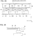
- Fig. 3A is a side view schematically showing the developing agent containers 200, the image forming units 10K, 10C, 10M and 10Y, and the ducts 22 connecting them to each other in the image forming apparatus 1 according to the first embodiment
- Fig. 3B is a diagram showing a conveyance spiral 25 provided in the duct 22. While one duct 22 is shown in Fig. 3A , four ducts 22K, 22C, 22M and 22Y are actually provided as shown in Fig. 2 .
- the developing agent stored in the developing agent container 200 is supplied from the coupling part 21 to the inside of the duct 22 by means of dropping.
- the conveyance spiral 25 as a conveyance member for conveying the developing agent is provided, and the conveyance spiral 25 conveys the developing agent from the coupling part 21 to the connection part 23 along the duct 22.
- the developing agent conveyed to the connection part 23 through the duct 22 is supplied to the image forming unit 10 by means of dropping.
- the conveyance spiral 25 is arranged substantially throughout the whole range of the duct 22 in its lengthwise direction and rotates around a rotation axis extending in the lengthwise direction of the duct 22.
- the conveyance spiral 25 is driven by a developing agent supply motor 26.
- the developing agent supply motor 26 is provided for each conveyance spiral 25.
- Fig. 4 is a perspective view showing a state of the image forming apparatus 1 according to the first embodiment in which the top cover 102 is open.
- the top cover 102 is pivotably supported by a pivot shaft 105 provided in the vicinity of an end of the basket frame 101 in the +Y direction.
- the axial direction of the pivot shaft 105 is the X direction.
- the top cover 102 can be opened as indicated by the arrow A by pivoting the top cover 102 around the pivot shaft 105.
- the developing agent supply unit 20 including the developing agent containers 200K, 200C, 200M and 200Y and the ducts 22K, 22C, 22M and 22Y is supported by the top cover 102.
- the developing agent supply unit 20 also pivots in an opening direction as the direction indicated by the arrow A.
- the replacement of the developing agent container 200 is made with the top cover 102 open, in which case the coupling between the coupling part 21 and the developing agent container 200 is released.
- the developing agent containers 200 and the image forming unit 10 are connected to each other by the ducts 22.
- the developing agent containers 200 are directly attached to the image forming unit 10 without using the ducts 22.
- arrangement direction of the image forming units 10K, 10C, 10M and 10Y and the arrangement direction of the developing agent containers 200K, 200C, 200M and 200Y are orthogonal to each other in Figs. 1 to 4 , these arrangement directions may also be parallel to each other.
- Fig. 5 is an external perspective view schematically showing the structure of the developing agent container 200 according to the first embodiment.
- Figs. 6A and 6B are bottom views schematically showing the structure of an under surface 211 of a container 210 of the developing agent container 200.
- the developing agent container 200 includes the container 210 having the under surface 211 as a first surface having a supply hole 212 for the developing agent, a shutter 220 in a plate-like shape, and a seal sponge 230 that deforms elastically.
- one developing agent container 200 stores one type of developing agent.
- the container 210 storing the developing agent, has the under surface 211.
- the supply hole 212 as an opening is formed through the under surface 211.
- the under surface 211 of the container 210 includes guide rails 213 and 214 for guiding the shutter 220 in the +Y direction as a first direction and in the -Y direction as a direction opposite to the +Y direction.
- the shutter 220 is provided on the container 210 to be slidable along the guide rails 213 and 214.
- the shutter 220 reaches a closed position, for setting the supply hole 212 to a closed state, by moving in the +Y direction as a direction along the under surface 211.
- Fig. 5 and Fig. 6A show a case where the supply hole 212 is in the closed state.
- the shutter 220 reaches an open position, for setting the supply hole 212 to an open state, by moving in the -Y direction.
- Fig. 6B shows a case where the supply hole 212 is in the open state.
- the seal sponge 230 is stuck to a region of the under surface 211 of the container 210 surrounding the supply hole 212. Namely, an opening in the same shape as the supply hole 212 is formed at the center of the seal sponge 230.
- the seal sponge 230 is compressed between the under surface 211 and the shutter 220 and seals a gap between the under surface 211 and the shutter 220.
- the developing agent stored in the container 210 does not leak to the outside thanks to the seal sponge 230.
- the thickness of the seal sponge 230 is 3.085 mm and the compression amount of the seal sponge 230 due to the pressing by the shutter 220 is 0.735 mm, for example.
- a range of a satisfactory compression amount with respect to the thickness of the seal sponge 230 is desired to be within a range of 20 % to 30 % of the thickness of the seal sponge.
- the reason for the lower limit value is that there is the danger of insufficiency of sealability and leakage of the developing agent when the compression amount is less than 20 %.
- the reason for the upper limit value is that the danger of the curling, tearing or the like of the seal sponge 230 increases when the compression amount exceeds 30 %.
- the shutter 220 is 0.3 mm thick and made of metal, for example. However, the dimensions of the parts are not limited to the above-described values.
- the shutter 220 and the seal sponge 230 are configured so that a ridge line (referred to also as a "first ridge line part") of an edge part (referred to also as a “first edge part”) 221 of the shutter 220 facing the +Y direction is inclined with respect to a ridge line (referred to also as a "second ridge line part”) of an edge part (referred to also as a "second edge part”) 231 of the seal sponge 230 facing the supply hole 212 and the -Y direction.
- a ridge line referred to also as a "first ridge line part” of an edge part (referred to also as a "first edge part") 221 of the shutter 220 facing the +Y direction
- a ridge line referred to also as a "second ridge line part” of an edge part (referred to also as a "second edge part") 231 of the seal sponge 230 facing the supply hole 212 and the -Y direction.
- the shutter 220 has the first ridge line part that makes contact with the seal sponge 230 due to the movement of the shutter 220, in the edge part 221 on the front end side in the +Y direction
- the seal sponge 230 has the second ridge line part that makes contact with the shutter 220 due to the movement of the shutter 220 in the +Y direction, in the edge part 231 on the -Y direction side facing the supply hole 212
- the first ridge line part and the second ridge line part have a relationship in which one is inclined with respect to the other.
- the ridge line of the edge part 231 of the seal sponge 230 is a straight line in the X direction as a second direction orthogonal to the Y direction
- the ridge line of the edge part 221 of the shutter 220 includes a first part 2211 inclined with respect to the X direction and a second part 2212 inclined with respect to both of the X direction and the first part 2211.
- the shape of the edge part 221 of the shutter 220 viewed in the Z direction as a third direction orthogonal to both of the Y direction and the X direction is a V-shape.
- the first part 2211 and the second part 2212 gradually project in the +Y direction with the increase in the distance from a central position of the shutter 220 in the X direction.
- Figs. 7A1 to 7E1 are bottom views showing a closing operation of the supply hole 212 of the developing agent container 200 according to the first embodiment
- Figs. 7A2 to 7E2 are cross-sectional views showing the closing operation of the supply hole 212 of the developing agent container 200.
- Figs. 7A2 to 7E2 respectively show cross sections intersecting with Figs. 7A1 to 7E1 at the position of the line S7 - S7 shown in Fig. 7A1 .
- the shutter 220 moves from the open state shown in Figs. 7A1 and 7A2 in the +Y direction successively as shown in Figs. 7B1 and 7B2, Figs. 7C1 and 7C2 and Figs. 7D1 and 7D2 and finally shifts to the closed state shown in Figs. 7E1 and 7E2 .
- the shutter 220 moves from the closed state shown in Figs. 7E1 and 7E2 in the -Y direction successively as shown in Figs. 7D1 and 7D2, Figs. 7C1 and 7C2 and Figs. 7B1 and 7B2 and finally shifts to the open state shown in Figs. 7A1 and 7A2 .
- Figs. 8A1 to 8E1 are bottom views showing the closing operation of a supply hole of a developing agent container as a comparative example
- Figs. 8A2 to 8E2 are cross-sectional views showing the closing operation of the supply hole of the developing agent container as the comparative example
- Fig. 8F is a diagram showing a state in which the developing agent container in Fig. 8E1 is viewed in the direction of the arrow 8F.
- Figs. 8A2 to 8E2 respectively show cross sections intersecting with Figs. 8A1 to 8E1 at the position of the line S8 - S8 shown in Fig. 8A1 .
- the developing agent container as the comparative example differs from the developing agent container shown in Figs.
- the shutter 920 and the seal sponge 230 are configured so that a ridge line of an edge part 921 of the shutter 920 facing the +Y direction is parallel to the ridge line of the edge part 231 of the seal sponge 230 facing the supply hole 212 and the -Y direction.
- the shutter 920 moves from the open state shown in Figs. 8A1 and 8A2 in the +Y direction successively as shown in Figs. 8B1 and 8B2, Figs. 8C1 and 8C2 and Figs. 8D1 and 8D2 and finally shifts to the closed state shown in Figs. 8E1, 8E2 and 8F .
- the whole region of the edge part 921 of the shutter 920 facing the +Y direction simultaneously makes contact with the whole region of the edge part 231 of the seal sponge 230 facing the supply hole 212 and the -Y direction as shown in Figs.
- the edge part 221 of the shutter 220 facing the +Y direction is inclined with respect to the edge part 231 of the seal sponge 230 facing the supply hole 212 and the -Y direction as shown in Figs. 7C1 and 7C2 .
- Figs. 7C1 and 7C2 and Figs. 7D1 and 7D2 there occurs no situation in which the whole region of the edge part 221 of the shutter 220 facing the +Y direction simultaneously makes contact with the whole region of the edge part 231 of the seal sponge 230.
- the curling hardly occurs to the edge part of the seal sponge 230, and thus an advantage is obtained in that the leakage of the developing agent due to the curling of the seal sponge 230 hardly occurs.
- the outer shape of the seal sponge 230 is a rectangular shape and the shape of the opening of the seal sponge 230 is also a rectangular shape, and thus the length in the Y direction is relatively short and that is suitable for the downsizing of the developing agent container 200.
- the shape of the seal sponge 230 is simple and the processing cost can be cut down.
- the edge part 221 of the shutter 220 is in a V-shape, and thus the developing agent moves along the edge part 221 towards the central position in the X direction when the edge part 221 moves in the +Y direction, by which scattering of the developing agent accompanying the closing operation of the shutter 220 can be reduced.
- Figs. 9A1 and 9B1 are bottom views showing the closing operation of a supply hole 312 of a developing agent container according to a first modification of the first embodiment
- Figs. 9A2 and 9B2 are cross-sectional views showing the closing operation of the supply hole 312 of the developing agent container according to the first modification
- Figs. 9A2 and 9B2 respectively show cross sections intersecting with Figs. 9A1 and 9B1 at the position of the line S9 - S9 shown in Fig. 9A1 .
- a ridge line of an edge part (second edge part) 331 of a seal sponge 330 includes a third part 3311 inclined with respect to the X direction orthogonal to the Y direction and a fourth part 3312 inclined with respect to both of the X direction and the third part 3311.
- a ridge line of an edge part (first edge part) 321 of a shutter 320 is a straight line in the X direction.
- the ridge line (referred to also as a "first ridge line part”) of the edge part 321 of the shutter 320 facing the +Y direction is inclined with respect to the ridge line (referred to also as a "second ridge line part") of the edge part 331 of the seal sponge 330 facing the supply hole 312 and the -Y direction as shown in Figs. 9A1 and 9A2 .
- the shutter 320 has the first ridge line part that makes contact with the seal sponge 330 due to the movement of the shutter 320, in the edge part 321 on the front end side in the +Y direction
- the seal sponge 330 has the second ridge line part that makes contact with the shutter 320 due to the movement of the shutter 320 in the +Y direction, in the edge part 331 on the -Y direction side facing the supply hole 312, and the first ridge line part and the second ridge line part have the relationship in which one is inclined with respect to the other.
- the shutter 320 is in a rectangular shape, and thus the shape is simple and the processing cost can be cut down.
- the edge part 331 of the seal sponge 330 is in a V-shape, and thus the developing agent moves along the edge part 331 towards the central position in the X direction when the shutter 320 moves in the +Y direction, by which the scattering of the developing agent accompanying the closing operation of the shutter 320 can be reduced.
- Figs. 10A1 and 10B1 are bottom views showing the closing operation of the supply hole 212 of a developing agent container according to a second modification of the first embodiment
- Figs. 10A2 and 10B2 are cross-sectional views showing the closing operation of the supply hole 212 of the developing agent container according to the second modification
- Figs. 10A2 and 10B2 respectively show cross sections intersecting with Figs. 10A1 and 10B1 at the position of the line S10 - S10 shown in Fig. 10A1 .
- the ridge line of the edge part (second edge part) 231 of the seal sponge 230 is a straight line in the X direction orthogonal to the Y direction, and a ridge line of an edge part (first edge part) 421 of a shutter 420 is a straight line inclined with respect to the X direction.
- the ridge line (referred to also as a "first ridge line part”) of the edge part 421 of the shutter 420 facing the +Y direction is inclined with respect to the ridge line (referred to also as a "second ridge line part") of the edge part 231 of the seal sponge 230 facing the supply hole 212 and the -Y direction as shown in Figs. 10A1 and 10A2 .
- the shutter 420 has the first ridge line part that makes contact with the seal sponge 230 due to the movement of the shutter 420, in the edge part 421 on the front end side in the +Y direction
- the seal sponge 230 has the second ridge line part that makes contact with the shutter 420 due to the movement of the shutter 420 in the +Y direction, in the edge part 231 on the -Y direction side facing the supply hole 212
- the first ridge line part and the second ridge line part have the relationship in which one is inclined with respect to the other.
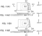
- Figs. 11A1 and 11B1 are bottom views showing the closing operation of a supply hole 512 of a developing agent container according to a third modification of the first embodiment
- Figs. 11A2 and 11B2 are cross-sectional views showing the closing operation of the supply hole 512 of the developing agent container according to the third modification.
- Figs. 11A2 and 11B2 respectively show cross sections intersecting with Figs. 11A1 and 11B1 at the position of the line S11 - S11 shown in Fig. 11A1 .
- a ridge line of a second edge part 531 of a seal sponge 530 is a straight line inclined with respect to the X direction orthogonal to the Y direction, and the ridge line of the first edge part 321 of the shutter 320 is a straight line in the X direction.
- the ridge line (referred to also as a "first ridge line part”) of the edge part (first edge part) 321 of the shutter 320 facing the +Y direction is inclined with respect to the ridge line (referred to also as a "second ridge line part") of the edge part (second edge part) 531 of the seal sponge 530 facing the supply hole 512 and the -Y direction as shown in Figs. 11A1 and 11A2 .
- the shutter 320 has the first ridge line part that makes contact with the seal sponge 530 due to the movement of the shutter 320, in the edge part 321 on the front end side in the +Y direction
- the seal sponge 530 has the second ridge line part that makes contact with the shutter 320 due to the movement of the shutter 320 in the +Y direction, in the edge part 531 on the -Y direction side facing the supply hole 512
- the first ridge line part and the second ridge line part have the relationship in which one is inclined with respect to the other.
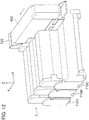
- Fig. 12 is a perspective view schematically showing internal structure of an image forming apparatus 2 according to a second embodiment.
- the image forming apparatus 2 includes image forming units 710Y, 710M and 710C that form developing agent images by using the electrophotographic method, a stage 720 as an attachment part to which a developing agent container 600 is attached, and the developing agent container 600.
- one developing agent container 600 stores three types of developing agents.
- the types of the developing agents stored in one developing agent container are not limited to three types.
- the image forming units 710Y, 710M and 710C form developing agent images of yellow, magenta and cyan.
- the image forming units 710Y, 710M and 710C are arranged side by side in the Y direction as a medium conveyance direction. Internal structure of each image forming unit 710Y, 710M, 710C is similar to that of each image forming unit 10Y, 10M, 10C shown in Fig. 1 .
- the stage 720 is provided on one side of the image forming units 710Y, 710M and 710C at one end in the X direction orthogonal to the Y direction as the medium conveyance direction.
- the developing agent container 600 is attached to the stage 720 in a detachable manner.
- the developing agent container 600 includes three developing agent container parts 640Y, 640M and 640C in a container 610.
- the developing agent container parts 640Y, 640M and 640C respectively store developing agents of yellow, magenta and cyan.
- a supply hole shifts from the closed state to the open state and the yellow, magenta and cyan developing agents stored in the developing agent container 600 are respectively supplied to the image forming units 710Y, 710M and 710C.
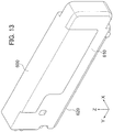
- Fig. 13 is an external perspective view schematically showing the developing agent container 600.
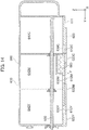
- Fig. 14 is a schematic cross-sectional view showing the developing agent container 600.
- Fig. 15 is an external perspective view schematically showing the structure of the developing agent container according to the second embodiment.
- the developing agent container 600 includes the container 610 having an under surface 611 as a first surface having supply holes 612Y, 612M and 612C for the developing agents, a shutter 620, and seal sponges 630Y, 630M and 630C.
- the developing agent container parts 640Y, 640M and 640C of the container 610 have the under surface 611.
- the supply holes 612Y, 612M and 612C as openings are formed through the under surface 611.
- the under surface 611 of the container 610 includes guide rails for guiding the shutter 620 in the +Y direction as the first direction and the -Y direction as the direction opposite to the +Y direction.
- the shutter 620 has openings 622Y, 622M and 622C that overlap with the supply holes 612Y, 612M and 612C when the shutter 620 is at the open position.
- the shutter 620 as a plate-shaped member is provided on the container 610 to be slidable in the +Y direction and the -Y direction.
- the shutter 620 sets the supply holes 612Y, 612M and 612C to the closed state by moving in the +Y direction as a direction along the under surface 611.
- Fig. 14 and 15 show a case where the supply holes 612Y, 612M and 612C are in the closed state.
- the shutter 620 sets the supply holes 612Y, 612M and 612C to the open state by moving in the -Y direction.
- the seal sponges 630Y, 630M and 630C are stuck to regions of the under surface 611 of the container 610 surrounding the supply holes 612Y, 612M and 612C. Namely, an opening in the same shape as the supply hole 612Y, 612M, 612C is formed in a central region of each seal sponge 630Y, 630M, 630C.
- the thickness and the compression amount of each seal sponge 630Y, 630M, 630C are the same as those in the first embodiment.
- the seal sponges 630Y, 630M and 630C are compressed between the under surface 611 and the shutter 620 and seal a gap between the under surface 611 and the shutter 620.
- the developing agents stored in the developing agent container parts 640Y, 640M and 640C of container 610 do not leak to the outside thanks to the seal sponges 630Y, 630M and 630C.
- the developing agent container 600 includes the developing agent container parts 640Y, 640M and 640C, the supply holes 612Y, 612M and 612C provided on the under surface 611, the shutter 620, a spring 660 as a biasing member for applying pressing force in the +Y direction to the shutter 620, and a stirring member 650 that stirs the developing agents stored in the developing agent container parts 640Y, 640M and 640C.
- Fig. 16 is a perspective view showing a state of the developing agent container 600 according to the second embodiment in the middle of the closing operation of the shutter 620.
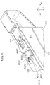
- Fig. 17 is a perspective view showing a state of the developing agent container 600 according to the second embodiment when the closing operation of the shutter 620 is completed.
- a ridge line of an edge part (second edge part) 631Y, 631M, 631C of each seal sponge 630Y, 630M, 630C is a straight line in the X direction orthogonal to the Y direction.
- a ridge line of each edge part (first edge part) 621Y, 621M, 621C of the shutter 620 includes a first part 6211 inclined with respect to the X direction and a second part 6212 inclined with respect to the X direction and the first part 6211.
- each edge part 621Y, 621M, 621C of the shutter 620 is viewed in the Z direction as the third direction orthogonal to both of the Y direction and the X direction, the shape of each edge part 621Y, 621M, 621C is a V-shape.
- the first part 6211 and the second part 6212 gradually project in the +Y direction with the increase in the distance from a central position of the shutter 620 in the X direction.
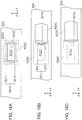
- Figs. 18A to 18C are bottom views showing the closing operation of the supply hole 612C of the developing agent container 600 according to the second embodiment.
- the closing operation of the shutter 620 the shutter 620 moves from the open state shown in Fig. 18A to the position shown in Fig. 18B and finally shifts to the closed state shown in Fig. 18C .
- the ridge line (referred to also as a "first ridge line part”) of the edge part 621C of the shutter 620 facing the +Y direction is inclined with respect to the ridge line (referred to also as a "second ridge line part”) of the edge part 631C of the seal sponge 630C facing the supply hole 612C and the -Y direction as shown in Fig. 18B .
- the shutter 620 has the first ridge line part that makes contact with the seal sponge 630C due to the movement of the shutter 620, in the edge part 621C on the front end side in the +Y direction, the seal sponge 630C has the second ridge line part that makes contact with the shutter 620 due to the movement of the shutter 620 in the +Y direction, in the edge part 631C on the -Y direction side facing the supply hole 612C, and the first ridge line part and the second ridge line part have the relationship in which one is inclined with respect to the other.
- the curling hardly occurs to the edge parts 631Y, 631M and 631C of the seal sponges 630Y, 630M and 630C, and thus an advantage is obtained in that the leakage of a developing agents due to the curling of the seal sponge 630Y, 630M or 630C hardly occurs.
Landscapes
- Physics & Mathematics (AREA)
- General Physics & Mathematics (AREA)
- Dry Development In Electrophotography (AREA)
- Electrophotography Configuration And Component (AREA)
Abstract
Provided is structure in which curling hardly occurs to a seal sponge. A developing agent container includes: a container 210 including an under surface 211 having a supply hole 212; a shutter 220 that sets the supply hole 212 to a closed state by moving in a +Y direction and sets the supply hole 212 to an open state by moving in a -Y direction; and a seal sponge 230 that is stuck to a region of the under surface 211 surrounding the supply hole 212 and seals a gap between the under surface 211 and the shutter 220 when the supply hole 212 is in the closed state. The shutter 220 has a first ridge line part that makes contact with the seal sponge 230 due to the movement of the shutter 220, in an edge part 221 on a front end side in the +Y direction. The seal sponge 230 has a second ridge line part that makes contact with the shutter 220 due to the movement of the shutter 220 in the +Y direction, in an edge part 231 on the -Y direction's side facing the supply hole 212. The first ridge line part and the second ridge line part have a relationship in which one is inclined with respect to the other.
Description
- The present invention relates to a developing agent container and an image forming apparatus.
- To an image forming apparatus that forms an image on a medium by using the electrophotographic method, a developing agent container storing a developing agent is attached in order to supply the developing agent. The developing agent container is referred to also as a "toner cartridge". The developing agent container includes a container that stores the developing agent, a supply hole (referred to also as a communication hole) for the developing agent as an opening formed through an under surface of the container, and a shutter provided to be slidable with respect to the container so as to open and close the supply hole. See Japanese Patent Application Publication No.
2009-122213 - Incidentally, to a part of the under surface of the container of the developing agent container around the supply hole, a seal sponge for sealing a gap between the under surface and the shutter is generally stuck. However, in the conventional developing agent container described above, the supply hole formed through the under surface of the container and an outlet hole as an opening formed through the shutter have the same shape. In this case, in the middle of moving the shutter situated at the open position to the closed position, the whole region of an edge part of the shutter simultaneously makes contact with the whole region of an edge part of the seal sponge facing the aforementioned opposite direction, and thus curling is likely to occur to the edge part of the seal sponge. When the curling occurs to the edge part of the seal sponge, a problem arises in that the sealing of the gap between the under surface of the container and the shutter by the seal sponge becomes imperfect and the developing agent leaks out even though the shutter is at the closed position.
- The object of the present invention, which has been made to resolve the above-described problem, is to provide a developing agent container having structure in which the curling hardly occurs to the seal sponge and an image forming apparatus including the developing agent container.
- A developing agent container according to an aspect of the present invention includes: a container including a first surface having a supply hole for a developing agent; a shutter that is provided on the container, sets the supply hole to a closed state by moving in a first direction as a direction along the first surface, and sets the supply hole to an open state by moving in a direction opposite to the first direction; and a seal sponge that is stuck to a region of the first surface surrounding the supply hole and seals a gap between the first surface and the shutter when the supply hole is in the closed state. The shutter has a first ridge line part that makes contact with the seal sponge due to the movement of the shutter, in a first edge part on a front end side in the first direction. The seal sponge has a second ridge line part that makes contact with the shutter due to the movement of the shutter in the first direction, in a second edge part on the opposite direction's side facing the supply hole. The first ridge line part and the second ridge line part have a relationship in which one is inclined with respect to the other.
- According to the present invention, the curling hardly occurs to the edge part of the seal sponge, and thus an advantage is obtained in that the leakage of the developing agent due to the curling of the seal sponge hardly occurs.
- In the attached drawings,
-
Fig. 1 is a diagram schematically showing vertical sectional structure of an image forming apparatus according to a first embodiment of the present invention; -
Fig. 2 is a plan view schematically showing arrangement of developing agent containers in the image forming apparatus according to the first embodiment; -
Fig. 3A is a side view schematically showing the developing agent containers, image forming units, and ducts connecting them to each other in the image forming apparatus according to the first embodiment, andFig. 3B is a diagram showing a conveyance spiral provided in the duct; -
Fig. 4 is a perspective view showing a state of the image forming apparatus according to the first embodiment in which a top cover is open; -
Fig. 5 is an external perspective view schematically showing the structure of the developing agent container according to the first embodiment; -
Figs. 6A and 6B are bottom views schematically showing the structure of an under surface of the developing agent container according to the first embodiment; -
Figs. 7A1 to 7E1 are bottom views showing a closing operation of a supply hole of the developing agent container according to the first embodiment, andFigs. 7A2 to 7E2 are cross-sectional views showing the closing operation of the supply hole of the developing agent container according to the first embodiment; -
Figs. 8A1 to 8E1 are bottom views showing the closing operation of a supply hole of a developing agent container as a comparative example,Figs. 8A2 to 8E2 are cross-sectional views showing the closing operation of the supply hole of the developing agent container as the comparative example, andFig. 8F is a diagram showing a state in which the developing agent container inFig. 8E1 is viewed in the direction of thearrow 8F; -
Figs. 9A1 and 9B1 are bottom views showing the closing operation of a supply hole of a developing agent container according to a first modification of the first embodiment, andFigs. 9A2 and 9B2 are cross-sectional views showing the closing operation of the supply hole of the developing agent container according to the first modification of the first embodiment; -
Figs. 10A1 and 10B1 are bottom views showing the closing operation of the supply hole of a developing agent container according to a second modification of the first embodiment, andFigs. 10A2 and 10B2 are cross-sectional views showing the closing operation of the supply hole of the developing agent container according to the second modification of the first embodiment; -
Figs. 11A1 and 11B1 are bottom views showing the closing operation of a supply hole of a developing agent container according to a third modification of the first embodiment, andFigs. 11A2 and 11B2 are cross-sectional views showing the closing operation of the supply hole of the developing agent container according to the third modification of the first embodiment; -
Fig. 12 is a perspective view schematically showing internal structure of an image forming apparatus according to a second embodiment of the present invention; -
Fig. 13 is an external perspective view schematically showing a developing agent container according to the second embodiment; -
Fig. 14 is a schematic cross-sectional view showing the developing agent container according to the second embodiment; -
Fig. 15 is an external perspective view schematically showing the structure of the developing agent container according to the second embodiment; -
Fig. 16 is a perspective view showing a state of the developing agent container according to the second embodiment in the middle of a closing operation of a shutter; -
Fig. 17 is a perspective view showing a state of the developing agent container according to the second embodiment when the closing operation of the shutter is completed; and -
Figs. 18A to 18C are bottom views showing the closing operation of a supply hole of the developing agent container according to the second embodiment. - A developing agent container and an image forming apparatus including the developing agent container according to each embodiment of the present invention will be described below with reference to drawings. Here, the image forming apparatus is a device that forms an image on a medium by using the electrophotographic method, such as a copy machine, a facsimile machine, a printer or a multi-function peripheral. The following embodiments are just examples for the purpose of illustration and a variety of modifications are possible within the scope of the present invention.
- Coordinate axes of an XYZ orthogonal coordinate system are shown in each drawing. An X-axis, a Y-axis and a Z-axis are coordinate axes respectively in a width direction, a lengthwise direction and a height direction of the developing agent container. In each embodiment, a +Y direction and a -Y direction are moving directions of a shutter that opens and closes a supply hole of the developing agent container for a developing agent. In the following description, the same components are assigned the same reference character.
-
Fig. 1 is a diagram schematically showing vertical sectional structure of animage forming apparatus 1 according to a first embodiment. Theimage forming apparatus 1 is a printer that forms a color image on a medium P. Theimage forming apparatus 1 includes amedium conveyance mechanism 70 that supplies and conveys a medium P such as a print sheet, animage forming section 100 that forms developing agent images made of developing agents on the medium P, and afixation device 85 that fixes the developing agent images on the medium P. Each developing agent is referred to also as a "toner". Each developing agent image is referred to also as a "toner image". Each developing agent container is referred to also as a "toner cartridge". - The
medium conveyance mechanism 70 includes asheet feed tray 71 that stores the media P, apickup roller 72 arranged to contact a medium P stored in thesheet feed tray 71, afeed roller 73 arranged adjacent to thepickup roller 72, and aretard roller 74 arranged to face thefeed roller 73. - The
sheet feed tray 71 stores the media P in a stacked state. Thepickup roller 72 rotates while contacting a medium P in thesheet feed tray 71 and thereby draws out the medium P from thesheet feed tray 71. Thefeed roller 73 sends out the medium P drawn out by thepickup roller 72 to a conveyance path R1. Theretard roller 74 prevents multifeed by giving conveyance resistance to the medium P sent out by thefeed roller 73. - Further, the
medium conveyance mechanism 70 includes conveyance roller pairs 75 and 76 along the conveyance path R1. Theconveyance roller pair 75 starts rotating with prescribed timing after a front end of the medium P makes contact with a nip part of the rollers and thereby conveys the medium P while correcting the skew of the medium P. Theconveyance roller pair 76 conveys the medium P fed from theconveyance roller pair 75 to theimage forming section 100. - The
image forming section 100 includesimage forming units transfer unit 80 that transfer the developing agent images onto the medium P. Print heads 13K, 13C, 13M and 13Y as exposure devices are arranged to respectively facephotosensitive drums 11 of theimage forming units - The
image forming units image forming unit image forming unit 10". Further, eachprint head - The
image forming unit 10 includes thephotosensitive drum 11 as an image carrier that carries the developing agent image, a chargingroller 12 as a charging member, adevelopment roller 14 as a developing agent carrier, asupply roller 15 as a supply member that supplies the developing agent to thedevelopment roller 14, and aunit frame 16 housing these components. - The charging
roller 12 is arranged to contact the surface of thephotosensitive drum 11 and rotates following the rotation of thephotosensitive drum 11. The chargingroller 12, to which charging voltage is applied, uniformly charges the surface of thephotosensitive drum 11. An electrostatic latent image is formed on the uniformly charged surface of thephotosensitive drum 11 by light irradiation by the print head 13. - The
development roller 14 is arranged to contact the surface of thephotosensitive drum 11. Thedevelopment roller 14, to which development voltage is applied, makes the developing agent adhere to the electrostatic latent image formed on the surface of thephotosensitive drum 11. Consequently, a developing agent image is formed on the surface of thephotosensitive drum 11. - The
supply roller 15 is arranged to contact or face the surface of thedevelopment roller 14. Thesupply roller 15, to which supply voltage is applied, supplies the toner to thedevelopment roller 14. In eachimage forming unit 10, a part including thedevelopment roller 14 and thesupply roller 15 is a part contributing to the development of the electrostatic latent image on thephotosensitive drum 11 and constitutes a development unit. - A housing of the
image forming apparatus 1 includes abasket frame 101 as a housing part that houses theimage forming units top cover 102 attached to thebasket frame 101, and abase frame 103 that supports these components. - Over the
image forming units agent containers image forming units agent containers top cover 102. - The developing
agent containers agent container agent container 200". - The print head 13 includes, for example, a light-emitting device array formed by arraying light-emitting devices such as LEDs (Light-Emitting Diodes) and a lens array that condenses light emitted from the light-emitting devices on the surface of the
photosensitive drum 11. The print head 13 is supplied with drive voltage based on print data, exposes the surface of thephotosensitive drum 11 to light, and thereby forms the electrostatic latent image corresponding to the print data. - The
transfer unit 80 includes atransfer belt 82 in an endless shape, adrive roller 83 and anidle roller 84 across which thetransfer belt 82 is stretched, and transferrollers photosensitive drums 11 of theimage forming units transfer belt 82. - The
transfer belt 82 travels while attracting and holding the medium P on its surface by electrostatic force. Thedrive roller 83 is rotated by a belt motor (not shown) and makes thetransfer belt 82 travel. Theidle roller 84 gives tension to thetransfer belt 82. Eachtransfer roller photosensitive drum 11 onto the medium P. - The
fixation device 85 is arranged on a downstream side of theimage forming section 100 in the conveyance path R2 of the medium P. Thefixation device 85 includes, for example, afixation roller 86 and apressure roller 87 pressed against thefixation roller 86. Thefixation roller 86 includes a built-in heater as a heat source and is rotated by a fixation motor. Thefixation roller 86 and thepressure roller 87 fix the developing agent images on the medium P by applying heat and pressure to the developing agent images transferred onto the medium P. - Ejection roller pairs 77 and 78 are arranged on the downstream side of the
fixation device 85 in a conveyance path R3 of the medium P. The ejection roller pairs 77 and 78 convey the medium P sent out from thefixation device 85 along the conveyance path R3 and eject the medium P to the outside of theimage forming apparatus 1. The top cover of theimage forming apparatus 1 includes astacker part 79 in which the media P ejected by the ejection roller pairs 77 and 78 are stacked. - The
image forming apparatus 1 includes are-conveyance mechanism 90 that turns over the medium P on which the developing agent images have been fixed and conveys the medium P to the aforementionedconveyance roller pair 76 for double-side printing. Further, a switchingguide 91 that guides the medium P sent out from thefixation device 85 to the ejection roller pairs 77 and 78 or to there-conveyance mechanism 90 is provided on the downstream side of thefixation device 85. - The
re-conveyance mechanism 90 includes conveyance roller pairs 92 and 94 and a switchingguide 94 that temporarily sends the medium P into a turnout path R4 and turns the medium P to switch the front and rear ends with each other and conveyance roller pairs 95, 96 and 97 that convey the medium P along a return conveyance path R5. The medium P after being conveyed by the conveyance roller pairs 95 to 97 through the return conveyance path R5 is conveyed to theimage forming section 100 via the conveyance roller pairs 75 and 76. Incidentally, there-conveyance mechanism 90 is unnecessary in cases where theimage forming apparatus 1 does not have the double-side printing function. - In
Fig. 1 , the moving direction of the medium P when the medium P passes through theimage forming section 100 is defined as the +Y direction. Further, the width direction of the medium P conveyed in the +Y direction is an X direction. The X direction is parallel to rotary shafts of the photosensitive drums 11. A Z direction is a direction orthogonal to the X direction and the Y direction. While an XY plane as a plane containing the X direction and the Y direction is inclined with respect to the horizontal plane inFig. 1 , the XY plane may also be designed to be in parallel with the horizontal plane. -
Fig. 2 is a plan view schematically showing the arrangement of the developingagent containers image forming apparatus 1 according to the first embodiment.Fig. 2 shows positional relationship of theimage forming units agent containers - The
image forming units agent containers image forming units -
Ducts agent containers image forming units duct coupling part agent container connection part image forming unit - In this example, the
coupling parts connection parts Fig. 2 . A developingagent supply unit 20 is formed by the developingagent containers ducts agent supply unit 20 is attached to thetop cover 102. Incidentally, the developing agent supply unit is referred to also as a "toner supply unit". Eachduct duct 22". Eachcoupling part part 21". Eachconnection part connection part 23". -
Fig. 3A is a side view schematically showing the developingagent containers 200, theimage forming units ducts 22 connecting them to each other in theimage forming apparatus 1 according to the first embodiment, andFig. 3B is a diagram showing aconveyance spiral 25 provided in theduct 22. While oneduct 22 is shown inFig. 3A , fourducts Fig. 2 . - The developing agent stored in the developing
agent container 200 is supplied from thecoupling part 21 to the inside of theduct 22 by means of dropping. Inside eachduct 22, theconveyance spiral 25 as a conveyance member for conveying the developing agent is provided, and theconveyance spiral 25 conveys the developing agent from thecoupling part 21 to theconnection part 23 along theduct 22. The developing agent conveyed to theconnection part 23 through theduct 22 is supplied to theimage forming unit 10 by means of dropping. - As shown in
Fig. 3B , theconveyance spiral 25 is arranged substantially throughout the whole range of theduct 22 in its lengthwise direction and rotates around a rotation axis extending in the lengthwise direction of theduct 22. Theconveyance spiral 25 is driven by a developingagent supply motor 26. The developingagent supply motor 26 is provided for eachconveyance spiral 25. However, it is also possible to transmit driving force of a common developingagent supply motor 26 to eachconveyance spiral 25 via a power transmission mechanism such as a clutch. -
Fig. 4 is a perspective view showing a state of theimage forming apparatus 1 according to the first embodiment in which thetop cover 102 is open. Thetop cover 102 is pivotably supported by apivot shaft 105 provided in the vicinity of an end of thebasket frame 101 in the +Y direction. The axial direction of thepivot shaft 105 is the X direction. Thetop cover 102 can be opened as indicated by the arrow A by pivoting thetop cover 102 around thepivot shaft 105. - As described above, the developing
agent supply unit 20 including the developingagent containers ducts top cover 102. Thus, when thetop cover 102 is opened, the developingagent supply unit 20 also pivots in an opening direction as the direction indicated by the arrow A. The replacement of the developingagent container 200 is made with thetop cover 102 open, in which case the coupling between thecoupling part 21 and the developingagent container 200 is released. - In the first embodiment, the developing
agent containers 200 and theimage forming unit 10 are connected to each other by theducts 22. However, it is also possible to employ a configuration in which the developingagent containers 200 are directly attached to theimage forming unit 10 without using theducts 22. - Further, while the arrangement direction of the
image forming units agent containers Figs. 1 to 4 , these arrangement directions may also be parallel to each other. -
Fig. 5 is an external perspective view schematically showing the structure of the developingagent container 200 according to the first embodiment.Figs. 6A and 6B are bottom views schematically showing the structure of an undersurface 211 of acontainer 210 of the developingagent container 200. The developingagent container 200 includes thecontainer 210 having theunder surface 211 as a first surface having asupply hole 212 for the developing agent, ashutter 220 in a plate-like shape, and aseal sponge 230 that deforms elastically. In the first embodiment, one developingagent container 200 stores one type of developing agent. - The
container 210, storing the developing agent, has theunder surface 211. Thesupply hole 212 as an opening is formed through the undersurface 211. Further, the undersurface 211 of thecontainer 210 includesguide rails shutter 220 in the +Y direction as a first direction and in the -Y direction as a direction opposite to the +Y direction. - The
shutter 220 is provided on thecontainer 210 to be slidable along theguide rails shutter 220 reaches a closed position, for setting thesupply hole 212 to a closed state, by moving in the +Y direction as a direction along the undersurface 211.Fig. 5 andFig. 6A show a case where thesupply hole 212 is in the closed state. Theshutter 220 reaches an open position, for setting thesupply hole 212 to an open state, by moving in the -Y direction.Fig. 6B shows a case where thesupply hole 212 is in the open state. - The
seal sponge 230 is stuck to a region of theunder surface 211 of thecontainer 210 surrounding thesupply hole 212. Namely, an opening in the same shape as thesupply hole 212 is formed at the center of theseal sponge 230. When thesupply hole 212 is in the closed state by theshutter 220, theseal sponge 230 is compressed between theunder surface 211 and theshutter 220 and seals a gap between theunder surface 211 and theshutter 220. When thesupply hole 212 is in the closed state by theshutter 220, the developing agent stored in thecontainer 210 does not leak to the outside thanks to theseal sponge 230. - Incidentally, the thickness of the
seal sponge 230 is 3.085 mm and the compression amount of theseal sponge 230 due to the pressing by theshutter 220 is 0.735 mm, for example. A range of a satisfactory compression amount with respect to the thickness of theseal sponge 230 is desired to be within a range of 20 % to 30 % of the thickness of the seal sponge. The reason for the lower limit value is that there is the danger of insufficiency of sealability and leakage of the developing agent when the compression amount is less than 20 %. The reason for the upper limit value is that the danger of the curling, tearing or the like of theseal sponge 230 increases when the compression amount exceeds 30 %. Theshutter 220 is 0.3 mm thick and made of metal, for example. However, the dimensions of the parts are not limited to the above-described values. - Further, in the example of
Fig. 5 ,Fig. 6A and Fig. 6B , theshutter 220 and theseal sponge 230 are configured so that a ridge line (referred to also as a "first ridge line part") of an edge part (referred to also as a "first edge part") 221 of theshutter 220 facing the +Y direction is inclined with respect to a ridge line (referred to also as a "second ridge line part") of an edge part (referred to also as a "second edge part") 231 of theseal sponge 230 facing thesupply hole 212 and the -Y direction. Put another way, theshutter 220 has the first ridge line part that makes contact with theseal sponge 230 due to the movement of theshutter 220, in theedge part 221 on the front end side in the +Y direction, theseal sponge 230 has the second ridge line part that makes contact with theshutter 220 due to the movement of theshutter 220 in the +Y direction, in theedge part 231 on the -Y direction side facing thesupply hole 212, and the first ridge line part and the second ridge line part have a relationship in which one is inclined with respect to the other. Specifically, the ridge line of theedge part 231 of theseal sponge 230 is a straight line in the X direction as a second direction orthogonal to the Y direction, and the ridge line of theedge part 221 of theshutter 220 includes afirst part 2211 inclined with respect to the X direction and asecond part 2212 inclined with respect to both of the X direction and thefirst part 2211. - In the example of
Fig. 5 ,Fig. 6A and Fig. 6B , the shape of theedge part 221 of theshutter 220 viewed in the Z direction as a third direction orthogonal to both of the Y direction and the X direction is a V-shape. In other words, thefirst part 2211 and thesecond part 2212 gradually project in the +Y direction with the increase in the distance from a central position of theshutter 220 in the X direction. -
Figs. 7A1 to 7E1 are bottom views showing a closing operation of thesupply hole 212 of the developingagent container 200 according to the first embodiment, andFigs. 7A2 to 7E2 are cross-sectional views showing the closing operation of thesupply hole 212 of the developingagent container 200.Figs. 7A2 to 7E2 respectively show cross sections intersecting withFigs. 7A1 to 7E1 at the position of the line S7 - S7 shown inFig. 7A1 . - In the closing operation of the
shutter 220, theshutter 220 moves from the open state shown inFigs. 7A1 and 7A2 in the +Y direction successively as shown inFigs. 7B1 and 7B2, Figs. 7C1 and 7C2 and Figs. 7D1 and 7D2 and finally shifts to the closed state shown inFigs. 7E1 and 7E2 . In contrast, in the opening operation of theshutter 220, theshutter 220 moves from the closed state shown inFigs. 7E1 and 7E2 in the -Y direction successively as shown inFigs. 7D1 and 7D2, Figs. 7C1 and 7C2 and Figs. 7B1 and 7B2 and finally shifts to the open state shown inFigs. 7A1 and 7A2 . -
Figs. 8A1 to 8E1 are bottom views showing the closing operation of a supply hole of a developing agent container as a comparative example,Figs. 8A2 to 8E2 are cross-sectional views showing the closing operation of the supply hole of the developing agent container as the comparative example, andFig. 8F is a diagram showing a state in which the developing agent container inFig. 8E1 is viewed in the direction of thearrow 8F.Figs. 8A2 to 8E2 respectively show cross sections intersecting withFigs. 8A1 to 8E1 at the position of the line S8 - S8 shown inFig. 8A1 . The developing agent container as the comparative example differs from the developing agent container shown inFigs. 7A1 to 7E1 and Figs. 7A2 to 7E2 in the shape of ashutter 920. In the developing agent container as the comparative example, theshutter 920 and theseal sponge 230 are configured so that a ridge line of anedge part 921 of theshutter 920 facing the +Y direction is parallel to the ridge line of theedge part 231 of theseal sponge 230 facing thesupply hole 212 and the -Y direction. - In the closing operation of the
shutter 920, theshutter 920 moves from the open state shown inFigs. 8A1 and 8A2 in the +Y direction successively as shown inFigs. 8B1 and 8B2, Figs. 8C1 and 8C2 and Figs. 8D1 and 8D2 and finally shifts to the closed state shown inFigs. 8E1, 8E2 and 8F . In the comparative example, however, in the middle of moving theshutter 920 situated at the open position to the closed position, the whole region of theedge part 921 of theshutter 920 facing the +Y direction simultaneously makes contact with the whole region of theedge part 231 of theseal sponge 230 facing thesupply hole 212 and the -Y direction as shown inFigs. 8C1 and 8C2 . At that time, a situation occurs in which the whole region of theedge part 921 of theshutter 920 simultaneously applies force to the whole region of theedge part 231 of theseal sponge 230. Thus, the curling can occur to theedge part 231 of theseal sponge 230. In this case, as shown inFigs. 8D2, 8E2 and 8F , a part of theseal sponge 230 in the vicinity of theedge part 231 peels off the undersurface 211, becomes pressed in the +Y direction, and forms apart 240 having an increased thickness. When the curling occurs to theedge part 231 of theseal sponge 230, the sealing of the gap between theunder surface 211 of the container and theshutter 920 by theseal sponge 230 becomes imperfect as shown inFig. 8F and the developing agent can leak out even though theshutter 920 is at the closed position. - In contrast, in the first embodiment, in the middle of moving the
shutter 220 situated at the open position to the closed position, theedge part 221 of theshutter 220 facing the +Y direction is inclined with respect to theedge part 231 of theseal sponge 230 facing thesupply hole 212 and the -Y direction as shown inFigs. 7C1 and 7C2 . In this case, as shown inFigs. 7C1 and 7C2 and Figs. 7D1 and 7D2 , there occurs no situation in which the whole region of theedge part 221 of theshutter 220 facing the +Y direction simultaneously makes contact with the whole region of theedge part 231 of theseal sponge 230. Accordingly, there occurs no situation in which the whole region of theedge part 221 of theshutter 220 simultaneously applies strong force to the whole region of theedge part 231 of theseal sponge 230. Thus, the curling hardly occurs to theedge part 231 of theseal sponge 230. - As described above, with the developing
agent container 200 according to the first embodiment, the curling hardly occurs to the edge part of theseal sponge 230, and thus an advantage is obtained in that the leakage of the developing agent due to the curling of theseal sponge 230 hardly occurs. - Further, in the developing
agent container 200 according to the first embodiment, the outer shape of theseal sponge 230 is a rectangular shape and the shape of the opening of theseal sponge 230 is also a rectangular shape, and thus the length in the Y direction is relatively short and that is suitable for the downsizing of the developingagent container 200. In addition, the shape of theseal sponge 230 is simple and the processing cost can be cut down. - Furthermore, in the developing
agent container 200 according to the first embodiment, theedge part 221 of theshutter 220 is in a V-shape, and thus the developing agent moves along theedge part 221 towards the central position in the X direction when theedge part 221 moves in the +Y direction, by which scattering of the developing agent accompanying the closing operation of theshutter 220 can be reduced. -
Figs. 9A1 and 9B1 are bottom views showing the closing operation of asupply hole 312 of a developing agent container according to a first modification of the first embodiment, andFigs. 9A2 and 9B2 are cross-sectional views showing the closing operation of thesupply hole 312 of the developing agent container according to the first modification.Figs. 9A2 and 9B2 respectively show cross sections intersecting withFigs. 9A1 and 9B1 at the position of the line S9 - S9 shown inFig. 9A1 . - A ridge line of an edge part (second edge part) 331 of a
seal sponge 330 includes athird part 3311 inclined with respect to the X direction orthogonal to the Y direction and afourth part 3312 inclined with respect to both of the X direction and thethird part 3311. A ridge line of an edge part (first edge part) 321 of ashutter 320 is a straight line in the X direction. - In the first modification, in the middle of moving the
shutter 320 situated at the open position to the closed position, the ridge line (referred to also as a "first ridge line part") of theedge part 321 of theshutter 320 facing the +Y direction is inclined with respect to the ridge line (referred to also as a "second ridge line part") of theedge part 331 of theseal sponge 330 facing thesupply hole 312 and the -Y direction as shown inFigs. 9A1 and 9A2 . Put another way, theshutter 320 has the first ridge line part that makes contact with theseal sponge 330 due to the movement of theshutter 320, in theedge part 321 on the front end side in the +Y direction, theseal sponge 330 has the second ridge line part that makes contact with theshutter 320 due to the movement of theshutter 320 in the +Y direction, in theedge part 331 on the -Y direction side facing thesupply hole 312, and the first ridge line part and the second ridge line part have the relationship in which one is inclined with respect to the other. In this case, as shown inFigs. 9A1 and 9A2 , there occurs no situation in which the whole region of theedge part 321 of theshutter 320 facing the +Y direction simultaneously makes contact with the whole region of the edge of theedge part 331 of theseal sponge 330. Accordingly, there occurs no situation in which the whole region of theedge part 321 of theshutter 320 simultaneously applies strong force to the whole region of theedge part 331 of theseal sponge 330. Thus, the curling hardly occurs to theedge part 331 of theseal sponge 330. - Further, in the developing agent container according to the first modification, the
shutter 320 is in a rectangular shape, and thus the shape is simple and the processing cost can be cut down. - Furthermore, in the developing agent container according to the first modification, the
edge part 331 of theseal sponge 330 is in a V-shape, and thus the developing agent moves along theedge part 331 towards the central position in the X direction when theshutter 320 moves in the +Y direction, by which the scattering of the developing agent accompanying the closing operation of theshutter 320 can be reduced. -
Figs. 10A1 and 10B1 are bottom views showing the closing operation of thesupply hole 212 of a developing agent container according to a second modification of the first embodiment, andFigs. 10A2 and 10B2 are cross-sectional views showing the closing operation of thesupply hole 212 of the developing agent container according to the second modification.Figs. 10A2 and 10B2 respectively show cross sections intersecting withFigs. 10A1 and 10B1 at the position of the line S10 - S10 shown inFig. 10A1 . - The ridge line of the edge part (second edge part) 231 of the
seal sponge 230 is a straight line in the X direction orthogonal to the Y direction, and a ridge line of an edge part (first edge part) 421 of ashutter 420 is a straight line inclined with respect to the X direction. - In the second modification, in the middle of moving the
shutter 420 situated at the open position to the closed position, the ridge line (referred to also as a "first ridge line part") of theedge part 421 of theshutter 420 facing the +Y direction is inclined with respect to the ridge line (referred to also as a "second ridge line part") of theedge part 231 of theseal sponge 230 facing thesupply hole 212 and the -Y direction as shown inFigs. 10A1 and 10A2 . Put another way, theshutter 420 has the first ridge line part that makes contact with theseal sponge 230 due to the movement of theshutter 420, in theedge part 421 on the front end side in the +Y direction, theseal sponge 230 has the second ridge line part that makes contact with theshutter 420 due to the movement of theshutter 420 in the +Y direction, in theedge part 231 on the -Y direction side facing thesupply hole 212, and the first ridge line part and the second ridge line part have the relationship in which one is inclined with respect to the other. In this case, as shown inFigs. 10A1 and 10A2 , there occurs no situation in which the whole region of theedge part 421 of theshutter 420 facing the +Y direction simultaneously makes contact with the whole region of the edge of theedge part 231 of theseal sponge 230. Accordingly, there occurs no situation in which the whole region of theedge part 421 of theshutter 420 simultaneously applies strong force to the whole region of theedge part 231 of theseal sponge 230. Thus, the curling hardly occurs to theedge part 231 of theseal sponge 230. -
Figs. 11A1 and 11B1 are bottom views showing the closing operation of asupply hole 512 of a developing agent container according to a third modification of the first embodiment, andFigs. 11A2 and 11B2 are cross-sectional views showing the closing operation of thesupply hole 512 of the developing agent container according to the third modification.Figs. 11A2 and 11B2 respectively show cross sections intersecting withFigs. 11A1 and 11B1 at the position of the line S11 - S11 shown inFig. 11A1 . - A ridge line of a
second edge part 531 of aseal sponge 530 is a straight line inclined with respect to the X direction orthogonal to the Y direction, and the ridge line of thefirst edge part 321 of theshutter 320 is a straight line in the X direction. - In the third modification, in the middle of moving the
shutter 320 situated at the open position to the closed position, the ridge line (referred to also as a "first ridge line part") of the edge part (first edge part) 321 of theshutter 320 facing the +Y direction is inclined with respect to the ridge line (referred to also as a "second ridge line part") of the edge part (second edge part) 531 of theseal sponge 530 facing thesupply hole 512 and the -Y direction as shown inFigs. 11A1 and 11A2 . Put another way, theshutter 320 has the first ridge line part that makes contact with theseal sponge 530 due to the movement of theshutter 320, in theedge part 321 on the front end side in the +Y direction, theseal sponge 530 has the second ridge line part that makes contact with theshutter 320 due to the movement of theshutter 320 in the +Y direction, in theedge part 531 on the -Y direction side facing thesupply hole 512, and the first ridge line part and the second ridge line part have the relationship in which one is inclined with respect to the other. In this case, as shown inFigs. 11A1 and 11A2 , there occurs no situation in which the whole region of theedge part 321 of theshutter 320 facing the +Y direction simultaneously makes contact with the whole region of the edge of theedge part 531 of theseal sponge 530. Accordingly, there occurs no situation in which the whole region of theedge part 321 of theshutter 320 simultaneously applies strong force to the whole region of theedge part 531 of theseal sponge 530. Thus, the curling hardly occurs to theedge part 531 of theseal sponge 530. -
Fig. 12 is a perspective view schematically showing internal structure of animage forming apparatus 2 according to a second embodiment. As shown inFig. 12 , theimage forming apparatus 2 includesimage forming units stage 720 as an attachment part to which a developingagent container 600 is attached, and the developingagent container 600. In the second embodiment, one developingagent container 600 stores three types of developing agents. However, the types of the developing agents stored in one developing agent container are not limited to three types. - The
image forming units image forming units image forming unit image forming unit Fig. 1 . - The
stage 720 is provided on one side of theimage forming units agent container 600 is attached to thestage 720 in a detachable manner. - The developing
agent container 600 includes three developingagent container parts container 610. The developingagent container parts agent container 600 to thestage 720, a supply hole shifts from the closed state to the open state and the yellow, magenta and cyan developing agents stored in the developingagent container 600 are respectively supplied to theimage forming units -
Fig. 13 is an external perspective view schematically showing the developingagent container 600.Fig. 14 is a schematic cross-sectional view showing the developingagent container 600.Fig. 15 is an external perspective view schematically showing the structure of the developing agent container according to the second embodiment. The developingagent container 600 includes thecontainer 610 having an undersurface 611 as a first surface havingsupply holes shutter 620, and sealsponges - The developing
agent container parts container 610, storing the developing agents, have theunder surface 611. The supply holes 612Y, 612M and 612C as openings are formed through the undersurface 611. Further, the undersurface 611 of thecontainer 610 includes guide rails for guiding theshutter 620 in the +Y direction as the first direction and the -Y direction as the direction opposite to the +Y direction. As shown inFig. 14 and16 , theshutter 620 hasopenings supply holes shutter 620 is at the open position. - The
shutter 620 as a plate-shaped member is provided on thecontainer 610 to be slidable in the +Y direction and the -Y direction. Theshutter 620 sets thesupply holes surface 611.Fig. 14 and15 show a case where thesupply holes shutter 620 sets thesupply holes - The
seal sponges under surface 611 of thecontainer 610 surrounding thesupply holes supply hole seal sponge seal sponge supply holes shutter 620, theseal sponges under surface 611 and theshutter 620 and seal a gap between theunder surface 611 and theshutter 620. When thesupply holes shutter 620, the developing agents stored in the developingagent container parts container 610 do not leak to the outside thanks to theseal sponges - Further, the developing
agent container 600 includes the developingagent container parts supply holes under surface 611, theshutter 620, aspring 660 as a biasing member for applying pressing force in the +Y direction to theshutter 620, and a stirringmember 650 that stirs the developing agents stored in the developingagent container parts -
Fig. 16 is a perspective view showing a state of the developingagent container 600 according to the second embodiment in the middle of the closing operation of theshutter 620.Fig. 17 is a perspective view showing a state of the developingagent container 600 according to the second embodiment when the closing operation of theshutter 620 is completed. - A ridge line of an edge part (second edge part) 631Y, 631M, 631C of each
seal sponge shutter 620 includes afirst part 6211 inclined with respect to the X direction and asecond part 6212 inclined with respect to the X direction and thefirst part 6211. When eachedge part shutter 620 is viewed in the Z direction as the third direction orthogonal to both of the Y direction and the X direction, the shape of eachedge part first part 6211 and thesecond part 6212 gradually project in the +Y direction with the increase in the distance from a central position of theshutter 620 in the X direction. -
Figs. 18A to 18C are bottom views showing the closing operation of thesupply hole 612C of the developingagent container 600 according to the second embodiment. In the closing operation of theshutter 620, theshutter 620 moves from the open state shown inFig. 18A to the position shown inFig. 18B and finally shifts to the closed state shown inFig. 18C . - In the second embodiment, in the middle of moving the
shutter 620 situated at the open position to the closed position, the ridge line (referred to also as a "first ridge line part") of theedge part 621C of theshutter 620 facing the +Y direction is inclined with respect to the ridge line (referred to also as a "second ridge line part") of theedge part 631C of theseal sponge 630C facing thesupply hole 612C and the -Y direction as shown inFig. 18B . Put another way, theshutter 620 has the first ridge line part that makes contact with theseal sponge 630C due to the movement of theshutter 620, in theedge part 621C on the front end side in the +Y direction, theseal sponge 630C has the second ridge line part that makes contact with theshutter 620 due to the movement of theshutter 620 in the +Y direction, in theedge part 631C on the -Y direction side facing thesupply hole 612C, and the first ridge line part and the second ridge line part have the relationship in which one is inclined with respect to the other. In this case, as shown inFig. 18B , there occurs no situation in which the whole region of theedge part 621C of theshutter 620 facing the +Y direction simultaneously makes contact with the whole region of the edge of theedge part 631C of theseal sponge 630C. Accordingly, there occurs no situation in which the whole region of theedge part 621C of theshutter 620 simultaneously applies strong force to the whole region of theedge part 631C of theseal sponge 630C. Thus, the curling hardly occurs to theedge part 631C of theseal sponge 630C. Theother seal sponges seal sponge 630C. - As described above, with the developing
agent container 600 according to the second embodiment, the curling hardly occurs to theedge parts 631Y, 631M and 631C of theseal sponges seal sponge - 1, 2: image forming apparatus, 10, 10K, 10C, 10M, 10Y: image forming unit, 11: photosensitive drum, 12: charging roller, 13, 13K, 13C, 13M, 13Y: print head, 14: development roller, 15: supply roller, 21, 21K, 21C, 21M, 21Y: coupling part, 22, 22K, 22C, 22M, 22Y: duct, 23, 23K, 23C, 23M, 23Y: connection part, 25: conveyance spiral, 80: transfer unit, 85: fixation device, 100: image forming section, 101: basket frame, 102: top cover, 200, 200K, 200C, 200M, 200Y: developing agent container, 211, 311, 511: under surface, 212, 312, 512: supply hole, 220, 320, 420: shutter, 230, 330, 530: seal sponge, 231, 331, 531: edge part, 600: developing agent container, 610: container, 611: under surface, 612Y, 612M, 612C: supply hole, 620: shutter, 621Y, 621M, 621C: edge part, 622Y, 622M, 622C: opening, 630Y, 630M, 630C: seal sponge, 631Y, 631M, 631C: edge part, 640Y, 640M, 640C: developing agent container part, 650: stirring member, 660: spring, 710Y, 710M, 710C: image forming unit, 720: stage.
Claims (8)
- A developing agent container (200, 600) comprising:a container (210, 610) including a first surface (211, 311, 511, 611) having a supply hole (212, 312, 512, 612C, 612M, 612Y) for a developing agent;a shutter (220, 320, 420, 620) that is provided on the container, sets the supply hole (212, 312, 512, 612C, 612M, 612Y) to a closed state by moving in a first direction as a direction along the first surface (211, 311, 511, 611), and sets the supply hole (212, 312, 512, 612C, 612M, 612Y) to an open state by moving in a direction opposite to the first direction; anda seal sponge (230, 330, 530, 630C, 630M, 630Y) that is stuck to a region of the first surface (211, 311, 511, 611) surrounding the supply hole (212, 312, 512, 612C, 612M, 612Y) and seals a gap between the first surface (211, 311, 511, 611) and the shutter (220, 320, 420, 620) when the supply hole (212, 312, 512, 612) is in the closed state, whereinthe shutter (220, 320, 420, 620) has a first ridge line part that makes contact with the seal sponge (230, 330, 530, 630C, 630M, 630Y) due to the movement of the shutter, in a first edge part on a front end side in the first direction,the seal sponge (230, 330, 530, 630C, 630M, 630Y) has a second ridge line part that makes contact with the shutter (220, 320, 420, 620) due to the movement of the shutter (220, 320, 420, 620) in the first direction, in a second edge part on the opposite direction's side facing the supply hole (212, 312, 512, 612), andthe first ridge line part and the second ridge line part have a relationship in which one is inclined with respect to the other.
- The developing agent container (200, 600) according to claim 1, wherein
the second ridge line part of the second edge part (231, 631) of the seal sponge (230, 630C, 630M, 630Y) is a straight line in a second direction orthogonal to the first direction, and
the first ridge line part of the first edge part (221, 621) of the shutter (220, 620) includes a first part (2211, 6211) that is inclined with respect to the second direction and a second part (2212, 6212) that is inclined with respect to the second direction and the first part. - The developing agent container (200) according to claim 2, wherein
a shape of the first edge part (221) of the shutter (220) viewed in a third direction orthogonal to both of the first direction and the second direction is a V-shape, and
the first part (2211) and the second part (2212) gradually project in the first direction with the increase in distance from a central position of the shutter in the second direction. - The developing agent container (600) according to claim 2, wherein
a shape of the first edge part of the shutter (620) viewed in a third direction orthogonal to both of the first direction and the second direction is a V-shape, and
the first part and the second part gradually project in the first direction with the increase in distance from a central position of the shutter in the third direction. - The developing agent container (200) according to claim 1, wherein
the second ridge line part of the second edge part (231) of the seal sponge (230) is a straight line in a second direction orthogonal to the first direction, and
the first ridge line part of the first edge part (421) of the shutter (420) is a straight line inclined with respect to the second direction. - The developing agent container (200) according to claim 1, wherein
the second ridge line part of the second edge part (531) of the seal sponge (530) is a straight line inclined with respect to a second direction orthogonal to the first direction, and
the first ridge line part of the first edge part (321) of the shutter (320) is a straight line in the second direction. - The developing agent container (200) according to claim 1, wherein
the second ridge line part of the second edge part (331) of the seal sponge (330) includes a third part (3311) that is inclined with respect to a second direction orthogonal to the first direction and a fourth part (3312) that is inclined with respect to the second direction and the third part, and
the first ridge line part of the first edge part (321) of the shutter (320) is a straight line in the second direction. - An image forming apparatus (1, 2) comprising the developing agent container (200, 600) according to any one of claims 1 to 7.
Applications Claiming Priority (1)
| Application Number | Priority Date | Filing Date | Title |
|---|---|---|---|
| JP2019032439A JP7387988B2 (en) | 2019-02-26 | 2019-02-26 | Developer container and image forming device |
Publications (1)
| Publication Number | Publication Date |
|---|---|
| EP3702845A1 true EP3702845A1 (en) | 2020-09-02 |
Family
ID=69177053
Family Applications (1)
| Application Number | Title | Priority Date | Filing Date |
|---|---|---|---|
| EP20152385.9A Withdrawn EP3702845A1 (en) | 2019-02-26 | 2020-01-17 | Developing agent container and image forming apparatus |
Country Status (4)
| Country | Link |
|---|---|
| US (1) | US10976687B2 (en) |
| EP (1) | EP3702845A1 (en) |
| JP (1) | JP7387988B2 (en) |
| CN (1) | CN111610703B (en) |
Citations (3)
| Publication number | Priority date | Publication date | Assignee | Title |
|---|---|---|---|---|
| JP2009122213A (en) | 2007-11-13 | 2009-06-04 | Panasonic Corp | Toner cartridge, recording device, process cartridge, and shutter opening / closing device |
| US20120163877A1 (en) * | 2009-09-04 | 2012-06-28 | Kenji Kikuchi | Toner container and image forming apparatus with a secure seal |
| US20130216257A1 (en) * | 2012-02-20 | 2013-08-22 | Kyocera Document Solutions Inc. | Developer transporting mechanism, developing device with the same, and image forming apparatus |
Family Cites Families (13)
| Publication number | Priority date | Publication date | Assignee | Title |
|---|---|---|---|---|
| JP3907300B2 (en) * | 1998-02-05 | 2007-04-18 | 富士ゼロックス株式会社 | Development device |
| JP2007052287A (en) * | 2005-08-18 | 2007-03-01 | Murata Mach Ltd | Image forming apparatus |
| US8023864B2 (en) * | 2007-04-27 | 2011-09-20 | Brother Kogyo Kabushiki Kaisha | Toner cartridge and developing apparatus |
| JP2008275874A (en) * | 2007-04-27 | 2008-11-13 | Brother Ind Ltd | Toner cartridge and developing device |
| JP4974034B2 (en) * | 2009-03-31 | 2012-07-11 | 株式会社沖データ | Developer container, image forming unit, and image forming apparatus |
| JP2011158509A (en) * | 2010-01-29 | 2011-08-18 | Konica Minolta Business Technologies Inc | Toner replenishing device |
| JP4947187B2 (en) * | 2010-05-17 | 2012-06-06 | ブラザー工業株式会社 | Toner box and developing device |
| JP2012037555A (en) * | 2010-08-03 | 2012-02-23 | Brother Ind Ltd | Toner storage body |
| JP5585414B2 (en) * | 2010-11-25 | 2014-09-10 | 富士ゼロックス株式会社 | Powder container and powder processing apparatus using the same |
| JP2014021246A (en) * | 2012-07-18 | 2014-02-03 | Konica Minolta Inc | Image forming apparatus |
| JP5896358B2 (en) * | 2013-01-21 | 2016-03-30 | 株式会社沖データ | Developer container, developing device, and image forming apparatus |
| US9477177B2 (en) * | 2014-09-02 | 2016-10-25 | Lexmark International, Inc. | Toner cartridge having a shutter lock mechanism |
| JP6866745B2 (en) * | 2017-04-19 | 2021-04-28 | 京セラドキュメントソリューションズ株式会社 | Developer transfer mechanism, developer equipped with it, and image forming apparatus |
-
2019
- 2019-02-26 JP JP2019032439A patent/JP7387988B2/en active Active
-
2020
- 2020-01-17 EP EP20152385.9A patent/EP3702845A1/en not_active Withdrawn
- 2020-01-17 US US16/746,104 patent/US10976687B2/en active Active
- 2020-01-20 CN CN202010067084.6A patent/CN111610703B/en active Active
Patent Citations (3)
| Publication number | Priority date | Publication date | Assignee | Title |
|---|---|---|---|---|
| JP2009122213A (en) | 2007-11-13 | 2009-06-04 | Panasonic Corp | Toner cartridge, recording device, process cartridge, and shutter opening / closing device |
| US20120163877A1 (en) * | 2009-09-04 | 2012-06-28 | Kenji Kikuchi | Toner container and image forming apparatus with a secure seal |
| US20130216257A1 (en) * | 2012-02-20 | 2013-08-22 | Kyocera Document Solutions Inc. | Developer transporting mechanism, developing device with the same, and image forming apparatus |
Also Published As
| Publication number | Publication date |
|---|---|
| US20200272070A1 (en) | 2020-08-27 |
| US10976687B2 (en) | 2021-04-13 |
| CN111610703A (en) | 2020-09-01 |
| JP7387988B2 (en) | 2023-11-29 |
| CN111610703B (en) | 2024-06-18 |
| JP2020134899A (en) | 2020-08-31 |
Similar Documents
| Publication | Publication Date | Title |
|---|---|---|
| US6968142B2 (en) | Process cartridge and image forming apparatus | |
| US7778568B2 (en) | Image forming apparatus having guide member for detachable unit | |
| US6453135B1 (en) | Image forming apparatus having a transfer material carrier unit or an intermediate transfer body unit | |
| US7929881B2 (en) | Process cartridge and electrophotographic image forming apparatus | |
| KR101324386B1 (en) | Developing device, developing cartridge, process cartridge and image forming apparatus | |
| US20200319589A1 (en) | Image forming apparatus | |
| US10139774B2 (en) | Developing device and image forming apparatus | |
| US9417604B2 (en) | Image forming apparatus | |
| US7570900B2 (en) | Process cartridge receiving from an image forming apparatus into which it is mounted a downstream-moving force during mounting and such image forming apparatus | |
| US7203447B2 (en) | Image forming apparatus with first and second openable portions | |
| CN104932223A (en) | Image forming apparatus | |
| JP2004109455A (en) | Image forming apparatus and image forming unit | |
| US11782383B2 (en) | Process cartridge | |
| US20130121721A1 (en) | Developer conveyance apparatus developing apparatus and process cartridge | |
| US11016411B2 (en) | Process cartridge, developing apparatus, and image forming apparatus | |
| CN111610703B (en) | Developer container and image forming apparatus | |
| JP6310374B2 (en) | Image forming unit, developer container, and image forming apparatus | |
| JP5908434B2 (en) | Image forming apparatus | |
| JP4781087B2 (en) | Image forming apparatus | |
| JP7782183B2 (en) | Drive device and image forming apparatus | |
| JP7396051B2 (en) | Covering mechanism and image forming device | |
| JP2019120713A (en) | Image formation device | |
| US9488956B2 (en) | Image forming apparatus having drawer | |
| JP2020008783A (en) | Image forming apparatus | |
| JP2019045554A (en) | Developer storage unit, image forming unit and image forming apparatus |
Legal Events
| Date | Code | Title | Description |
|---|---|---|---|
| PUAI | Public reference made under article 153(3) epc to a published international application that has entered the european phase |
Free format text: ORIGINAL CODE: 0009012 |
|
| STAA | Information on the status of an ep patent application or granted ep patent |
Free format text: STATUS: THE APPLICATION HAS BEEN PUBLISHED |
|
| AK | Designated contracting states |
Kind code of ref document: A1 Designated state(s): AL AT BE BG CH CY CZ DE DK EE ES FI FR GB GR HR HU IE IS IT LI LT LU LV MC MK MT NL NO PL PT RO RS SE SI SK SM TR |
|
| AX | Request for extension of the european patent |
Extension state: BA ME |
|
| STAA | Information on the status of an ep patent application or granted ep patent |
Free format text: STATUS: THE APPLICATION IS DEEMED TO BE WITHDRAWN |
|
| 18D | Application deemed to be withdrawn |
Effective date: 20210303 |