EP3702753B1 - Retraction device and feeding mechanism having same - Google Patents
Retraction device and feeding mechanism having same Download PDFInfo
- Publication number
- EP3702753B1 EP3702753B1 EP18884246.2A EP18884246A EP3702753B1 EP 3702753 B1 EP3702753 B1 EP 3702753B1 EP 18884246 A EP18884246 A EP 18884246A EP 3702753 B1 EP3702753 B1 EP 3702753B1
- Authority
- EP
- European Patent Office
- Prior art keywords
- spindle
- pull rod
- face
- retraction device
- flat face
- Prior art date
- Legal status (The legal status is an assumption and is not a legal conclusion. Google has not performed a legal analysis and makes no representation as to the accuracy of the status listed.)
- Active
Links
Images


Classifications
-
- B—PERFORMING OPERATIONS; TRANSPORTING
- B26—HAND CUTTING TOOLS; CUTTING; SEVERING
- B26D—CUTTING; DETAILS COMMON TO MACHINES FOR PERFORATING, PUNCHING, CUTTING-OUT, STAMPING-OUT OR SEVERING
- B26D7/00—Details of apparatus for cutting, cutting-out, stamping-out, punching, perforating, or severing by means other than cutting
- B26D7/06—Arrangements for feeding or delivering work of other than sheet, web, or filamentary form
- B26D7/0616—Arrangements for feeding or delivering work of other than sheet, web, or filamentary form by carriages, e.g. for slicing machines
-
- B—PERFORMING OPERATIONS; TRANSPORTING
- B26—HAND CUTTING TOOLS; CUTTING; SEVERING
- B26D—CUTTING; DETAILS COMMON TO MACHINES FOR PERFORATING, PUNCHING, CUTTING-OUT, STAMPING-OUT OR SEVERING
- B26D7/00—Details of apparatus for cutting, cutting-out, stamping-out, punching, perforating, or severing by means other than cutting
- B26D7/06—Arrangements for feeding or delivering work of other than sheet, web, or filamentary form
-
- G—PHYSICS
- G01—MEASURING; TESTING
- G01N—INVESTIGATING OR ANALYSING MATERIALS BY DETERMINING THEIR CHEMICAL OR PHYSICAL PROPERTIES
- G01N1/00—Sampling; Preparing specimens for investigation
- G01N1/02—Devices for withdrawing samples
- G01N1/04—Devices for withdrawing samples in the solid state, e.g. by cutting
- G01N1/06—Devices for withdrawing samples in the solid state, e.g. by cutting providing a thin slice, e.g. microtome
-
- G—PHYSICS
- G01—MEASURING; TESTING
- G01N—INVESTIGATING OR ANALYSING MATERIALS BY DETERMINING THEIR CHEMICAL OR PHYSICAL PROPERTIES
- G01N1/00—Sampling; Preparing specimens for investigation
- G01N1/02—Devices for withdrawing samples
- G01N1/04—Devices for withdrawing samples in the solid state, e.g. by cutting
- G01N1/06—Devices for withdrawing samples in the solid state, e.g. by cutting providing a thin slice, e.g. microtome
- G01N2001/065—Drive details
Definitions
- the present invention relates to a technical field of microtomes, and more particularly to a retraction device and a feeding mechanism having the same.
- the rotary microtome usually includes an object carriage for carrying a specimen holder which holds a specimen to be cut.
- the object carriage moves up and down in a vertical path of the rotary microtome.
- the specimen passes through a cutter fixedly arranged on the rotary microtome from an upper position to complete one section. After one section, the specimen holder is located under the cutter.
- a micro feeding mechanism for the rotary microtome has a retraction device.
- the function is realized by a pair of spring washers and a pull rod.
- the pull rod is pulled to pull the feeding mechanism back, and when the retraction is not needed, the pull rod is released, such that the feeding mechanism is moved to an original position by the pair of spring washers.
- the micro feeding mechanism in the related art refers to that the micro feeding mechanism can drive the specimen to feed 0.1 ⁇ m to 100 ⁇ m by turning a handwheel one circle.
- a movable step realizes a switch between pulling back and releasing of the pull rod by abutting against the pull rod at either a high point or a low point of the movable step.
- the high point of the movable step abuts against the pull rod such that the pull rod pulls the feeding mechanism back
- the low point of the movable step abuts against the pull rod such that the pull rod is moved to its original position.
- the movable step switches the pull rod between the high point and the low point of the movable step by hitting an upper end piece and a lower end piece.
- the retracting mechanism includes an elastic piece, a retracting control block, a fixed disk, a sliding limiting piece, an upper jacking block and a lower jacking block; the elastic piece is located between a mounting plate and a limiting ring; the retracting control block is externally sleeved on a lead screw; one side of the retracting control block is hinged to the mounting plate; the fixed disk is fixed relative to the lead screw; the sliding limiting piece is provided with a groove matched with a control rod of the retracting control block; the depth of the upper part of the groove is greater than that of the lower part of the groove; the upper jacking block is used to allow the control rod to be located at the upper part of the groove; and the lower jacking block is used to allow the control rod to be located at the lower part of the groove, and drives the retracting control block to rotate. According to the retracting mechanism, after a movable seat moves down to the lowest
- the present invention aims to solve at least one of the technical problems in the related art to a certain extent.
- one objective of the present invention is to propose a retraction device which effectively reduces the noise of the retraction device during operation.
- Another objective of the present invention is to propose a feeding mechanism having the above retraction device.
- the present invention relates to a retraction device according to claim 1.
- FIG. 1 illustrates a perspective view of a retraction device and a feeding mechanism according to an embodiment of the present invention.
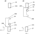
- FIG. 2 illustrates a schematic view of an operating unit according to an embodiment of the present invention, in which the operating unit is in a retraction position.
- FIG. 3 illustrates a schematic view of an operating unit according to an embodiment of the present invention, in which the operating unit is in a release position.
- FIG. 4 illustrates a schematic view of a movable member according to an embodiment of the present invention.
- a positive direction of X axis is a left direction, while a negative direction of X axis is a right direction; a positive direction of Y axis is a front direction while a negative direction of Y axis is a rear direction; a positive direction of Z axis is an up direction, while a negative direction of Z axis is a down direction.
- a retraction device 100 for a feeding mechanism of a rotary microtome includes a spindle 10 and an operating unit 20.
- the spindle 10 is movable along an axis direction thereof.
- the operating unit 20 is configured such that the spindle 10 is switchable between a retraction position and a release position, and the spindle 10 can move a predetermined distance towards or away from the operating unit 20 along an axis direction of the spindle 10 during the switching.
- the spindle 10 when in the release position, the spindle 10 is in the foremost position, by pulling the spindle 10 through the operating unit 20, the spindle 10 can move a predetermined distance towards the operating unit 20 to the retraction position along the axis direction of the spindle 10.
- the spindle 10 When in the retraction position, the spindle 10 is in the rearmost position, by releasing the spindle 10 through the operating unit 20, the spindle 10 moves away a predetermined distance from the operating unit 20 to the release position along the axis direction of the spindle 10, thereby realizing the retraction and release of the retraction device 100.
- the axis direction of the spindle 10 herein refers to a front-and-rear direction illustrated in FIG. 1 .
- the retraction device 100 may be used to drive the retraction and release of the feeding mechanism 1000 by moving the spindle 10 along the axis direction of the spindle 10.
- the operating unit 20 includes a pull rod 22 and a movable member 24.
- the pull rod 22 is a columnar shape extending along a left-and-right direction, and a first end of the pull rod 22 is connected to a first end of the spindle 10, such that the spindle 10 may be moved along the axis direction of the spindle 10 through the pull rod 22. Further, the pull rod 22 may be connected to the first end of the spindle 10 along a direction perpendicular to the axis direction of the spindle 10, such that the pull rod 22 can move the spindle 10 more lightly.
- the first end of the pull rod 22 herein refers to a left end illustrated in FIG. 1
- the first end of the spindle 10 herein refers to a rear end illustrated in FIG. 1 .
- the movable member 24 defines a step-shaped groove 242, and a second end of the pull rod 22 is received in the groove 242.
- the second end of the pull rod 22 herein refers to a right end illustrated in FIG. 1 .
- the groove 242 includes a first step 2421, a second step 2422 and an inclined face 2423 connecting the first step 2421 and the second step 2422 that are arranged along a first direction (the first step 2421, the second step 2422 and the inclined face 2423 are illustrated in FIG. 4 ), and a height of the second step 2422 is greater than a height of the first step 2421 in the axis direction of the spindle 10.
- the first direction herein refers to an up-and-down direction illustrated in FIG. 1
- the first step 2421 is located above the second step 2422.
- the movable member 24 is slidable relative to the pull rod 22 in the first direction, such that the pull rod 22 is switchable between the first step 2421 and the second step 2422 through the inclined face 2423, thereby reducing the noise of the retraction device 100 during operation.
- the pull rod 22 when in the retraction position, the pull rod 22 is received in the second step 2422, and when in the release position, the pull rod 22 is received in the first step 2411.
- the retraction device 100 may also include an elastic member (not illustrated) disposed between the spindle 10 and the operating unit 20 with a predetermined pre-load, such that when the spindle 10 is pulled, the spindle 10 compresses the elastic member to move to the retraction position, and when the spindle 10 is released, the spindle 10 moves back to the release position under an elastic restoring force of the elastic member.
- an elastic member not illustrated
- the operating unit 20 further includes a sliding groove member 26, the sliding groove member 26 extends in the first direction and is fixedly connected to the pull rod 22, and the movable member 24 is received in the sliding groove member 26, such that the movable member 24 is slidable relative to the sliding groove member 26 and the pull rod 22.
- the operating unit 20 also includes a first end piece 25 and a second end piece 27.
- the first end piece 25 and the second end piece 27 have fixed positions and are disposed opposite each other in the first direction, and the movable member 24 and the pull rod 22 are disposed between the first end piece 25 and the second end piece 27.
- the first end piece 25 and the second end piece 27 having fixed positions refer to the first end piece 25 and the second end piece 27 are arranged in a fixed position relative to the pull rod 22 and the movable member 24.
- the first end piece 25 is located above the second end piece, and the movable member 24 and the pull rod 22 are movable relative to the first end piece 25 and the second end piece 27 in the up-and-down direction, such that the first end piece 25 and the second end piece 27 define limit positions of movement of the movable member 24 along the up-and-down direction.
- the movable member 24 hits the first end piece 25 or the second end piece 27, such that sliding of the movable member 24 relative to the pull rod 22 can be realized, that is, switching of the pull rod 22 between the first step 2421 and the second step 2422 is realized.
- the first end piece 25 and the second end piece 27 may be made of a material with low Shore hardness, such as plastic, rubber, etc. In some embodiments, the first end piece 25 and the second end piece 27 may be made of a material with a Shore hardness of 42 to 70, in some embodiments, a material with a Shore hardness of 50, thereby further reducing the noise of the retraction device 100 during operation.
- the first step 2421 includes a first flat face 24211, a first cylinder face 24212 and a second flat face 24213.
- a radius of the first cylinder face 24212 is configured to suitably receive the pull rod 22.
- the radius of the first cylinder face 24212 is equal to a radius of the pull rod 22. It should be understood that the radius of the first cylinder face 24212 may also be greater than the radius of the pull rod 22.
- the first flat face 24211 extends along the axis direction of the spindle 10 and is tangentially connected to the first cylinder face 24212
- the second flat face 24213 extends along the first direction and is tangentially connected to the first cylinder face 24212.
- first flat face 24211 is perpendicular to the second flat face 24213.
- a length of the first flat face 24211 along the axis direction of the spindle 10 and a length of the second flat face 24213 along the first direction are respectively suitable for receiving the pull rod 22 to prevent the pull rod 22 from escaping.
- the length of the first flat face 24211 along the axis direction of the spindle 10 and the length of the second flat face 24213 along the first direction are respectively greater than a diameter of the pull rod 22.
- the length of the first flat face 24211 along the axis direction of the spindle 10 may be equal to the length of the second flat face 24213 in the first direction.
- the second step 2422 includes a third flat face 24221, a second cylinder face 24222 and a fourth flat face 24223.
- a radius of the second cylinder face 24222 is configured to suitably receive the pull rod 22.
- the radius of the second cylinder face 24222 is equal to a radius of the pull rod 22. It should be understood that the radius of the second cylinder face 24222 may also be greater than the radius of the pull rod 22.
- the third flat face 24221 extends along the axis direction of the spindle 10 and is tangentially connected to the second cylinder face 24222, and the fourth flat face 24223 extends along the first direction and is tangentially connected to the second cylinder face 24222.
- the third flat face 24221 is perpendicular to the fourth flat face 24223.
- a length of the third flat face 24221 along the axis direction of the spindle 10 and a length of the fourth flat face 24223 along the first direction are respectively suitable for receiving the pull rod 22 to prevent the pull rod 22 from escaping.
- the length of the third flat face 24221 along the axis direction of the spindle 10 and the length of the fourth flat face 24223 along the first direction are respectively greater than or equal to the diameter of the pull rod 22.
- the length of the third flat face 24221 along the axis direction of the spindle 10 is equal to the length of the fourth flat face 24223 in the first direction. It could be understood that the length of the third flat face 24221 along the axis direction of the spindle 10 is shorter than the length of the first flat face 24211 along the axis direction of the spindle 10.
- the inclined face 2423 connects a lower edge of the second flat face 24213 and an upper edge of the fourth flat face 24223.
- An inclined angle A of the inclined face 2423 relative to the first direction ranges from 2° to 5°, and in one embodiment, the inclined angle A is 3.6°.
- a length of the inclined face 2423 along the axis direction of the spindle 10, i.e. a height difference H between the first step 2421 and the second step 2422 ranges from 0.2mm to 0.6mm. In one embodiment, the height difference H is 0.5mm.
- the length L of the inclined face 2423 along the first direction ranges from 6mm to 10mm, and in one embodiment the length L is 8 mm. Therefore, such arrangement of the inclined face 2433 can further reduce the noise of the retraction device 100 during operation.
- the retraction device 100 is in the retraction position, the lower end face 246 of the movable member 24 abuts against the upper surface 272 of the second end piece 27, the pull rod 22 is received in the second step 2422, and the pull rod 22 abuts against the fourth flat face 24223.
- the pull rod 22 may be moved upward. Due to the effect of the elastic member, the pull rod 22 is compressed in the second step 2422, and the movable member 24, the sliding groove member 26 and the pull rod 22 move upward together.
- the retraction device 100 is in the release position, the upper end face 244 of the movable member 24 abuts against the lower surface 252 of the first end piece 25, the pull rod 22 is received in the first step 2421, and the pull rod 22 abuts against the second flat face 24213.
- the pull rod 22 may be moved downward. Due to the effect of the elastic member, the pull rod 22 is compressed in the first step 2421, and the movable member 24, the sliding groove member 26 and the pull rod 22 move downward together.
- the feeding mechanism 1000 includes an object carriage 200, a first slide base 300, a second slide base 400 and a retraction device 100 according to the above embodiments.
- the object carriage 200 is slidably connected to the first slide base 300, the first slide base 300 is slidably connected to the second slide base 400, and the second slide base 400 has a fixed position.
- the second end of the spindle 10 of the retraction device 100 is connected to the object carriage 200, and configured to drive the object carriage 200 to retract a predetermined distance relative to the first slide base 300 along the axis direction of the spindle 10.
- the object carriage 200 is slidable relative to the first slide base 300 along the front-and-rear direction
- the first slide base 300 is slidable relative to the second slide base 400 along the up-and-down direction.
- the second slide base 400 having a fixed position refers to the second slide base 400 is arranged in a fixed position relative to the first slide base 300, the object carriage 200 and the retraction device 100, so as to be able to support these components.
- the retraction device 100 includes a spindle 10 that is movable along an axis direction thereof and has a first end; and an operating unit 20 which includes a pull rod 22 and a movable member 24.
- the pull rod 22 has a first end and a second end, the movable member 24 defines a step-shaped groove 242, the first end of the pull rod 22 is connected to the first end of the spindle 10, the second end of the pull rod 22 is received in the groove 242.
- the groove 242 includes a first step 2421, a second step 2422 and an inclined face 2423 connecting the first step 2421 and the second step 2422 that are arranged along a first direction, and a height of the second step 2422 is greater than a height of the first step 2421 in the axis direction of the spindle 10.
- the movable member 24 is slidable relative to the pull rod 22 in the first direction, such that the pull rod 22 is switchable between the first step 2421 and the second step 2422 through the inclined face 2423, and thus the spindle 10 is switchable between a retraction position and a release position.
- the pull rod 22 When in the retraction position, the pull rod 22 is received in the second step 2422, and when in the release position, the pull rod 22 is received in the first step 2421.
- the arrangement of the inclined face 2423 connecting the first step 2421 and the second step 2422 effectively avoids the hit between components of the retraction device 100 during the operation, thereby effectively reducing the noise of the retraction device 100 during operation.
- first and second are used herein for purposes of description and are not intended to indicate or imply relative importance or significance or to imply the number of indicated technical features.
- the feature defined with “first” and “second” may include one or more of this feature.
- a plurality of means two or more than two, unless specified otherwise.
- the first feature "on” or “under” the second feature may be that the first and second features are in direct contact, or that the first and second features are in indirect contact through an intermediate medium.
- the first feature "on”, “above” and “on top of” the second feature may be that the first feature is directly above or obliquely above the second feature, or merely be that the first feature has a level higher than the second feature.
- the first feature "below”, “under” and “on bottom of” the second feature may be that the first feature is directly below or obliquely below the second feature, or merely be that the first feature has a level less than the second feature.
Landscapes
- Life Sciences & Earth Sciences (AREA)
- Forests & Forestry (AREA)
- Engineering & Computer Science (AREA)
- Mechanical Engineering (AREA)
- Physics & Mathematics (AREA)
- Health & Medical Sciences (AREA)
- Chemical & Material Sciences (AREA)
- Analytical Chemistry (AREA)
- Biochemistry (AREA)
- General Health & Medical Sciences (AREA)
- General Physics & Mathematics (AREA)
- Immunology (AREA)
- Pathology (AREA)
- Sampling And Sample Adjustment (AREA)
- Transmission Devices (AREA)
- Braking Arrangements (AREA)
Description
- The present invention relates to a technical field of microtomes, and more particularly to a retraction device and a feeding mechanism having the same.
- In a rotary microtome of the related art, the rotary microtome usually includes an object carriage for carrying a specimen holder which holds a specimen to be cut. The object carriage moves up and down in a vertical path of the rotary microtome. During the vertical movement, the specimen passes through a cutter fixedly arranged on the rotary microtome from an upper position to complete one section. After one section, the specimen holder is located under the cutter.
- When the specimen is moved back to the upper position, its surface will hit the cutter and the specimen may be damaged. Therefore, a micro feeding mechanism for the rotary microtome has a retraction device. The function is realized by a pair of spring washers and a pull rod. When retraction is needed, the pull rod is pulled to pull the feeding mechanism back, and when the retraction is not needed, the pull rod is released, such that the feeding mechanism is moved to an original position by the pair of spring washers. The micro feeding mechanism in the related art refers to that the micro feeding mechanism can drive the specimen to feed 0.1 µm to 100 µm by turning a handwheel one circle.
- A movable step realizes a switch between pulling back and releasing of the pull rod by abutting against the pull rod at either a high point or a low point of the movable step. When the retraction is needed, the high point of the movable step abuts against the pull rod such that the pull rod pulls the feeding mechanism back, and when the retraction is not needed, the low point of the movable step abuts against the pull rod such that the pull rod is moved to its original position. The movable step switches the pull rod between the high point and the low point of the movable step by hitting an upper end piece and a lower end piece.
- Due to a large step height between the high point and the low point of the movable step, a surface connecting the high point and the low point is too steep and the end pieces are too hard, a current retraction device has a large noise during operation.
-
CN106239574A discloses a retracting mechanism of a slicing machine. The retracting mechanism includes an elastic piece, a retracting control block, a fixed disk, a sliding limiting piece, an upper jacking block and a lower jacking block; the elastic piece is located between a mounting plate and a limiting ring; the retracting control block is externally sleeved on a lead screw; one side of the retracting control block is hinged to the mounting plate; the fixed disk is fixed relative to the lead screw; the sliding limiting piece is provided with a groove matched with a control rod of the retracting control block; the depth of the upper part of the groove is greater than that of the lower part of the groove; the upper jacking block is used to allow the control rod to be located at the upper part of the groove; and the lower jacking block is used to allow the control rod to be located at the lower part of the groove, and drives the retracting control block to rotate. According to the retracting mechanism, after a movable seat moves down to the lowest point, the lead screw can be retracted, blade sticking is prevented, and a sample and a blade can be protected effectively. - The present invention aims to solve at least one of the technical problems in the related art to a certain extent.
- To this end, one objective of the present invention is to propose a retraction device which effectively reduces the noise of the retraction device during operation.
- Another objective of the present invention is to propose a feeding mechanism having the above retraction device.
- The present invention is defined in the independent claims, and the preferable features according to the present invention are defined in the dependent claims.
-
-
FIG. 1 is a schematic view of a retraction device and a feeding mechanism according to an embodiment of the present invention. -
FIG. 2 is a schematic view of an operating unit according to an embodiment of the present invention, in which the operating unit is in a retraction position. -
FIG. 3 is a schematic view of an operating unit according to an embodiment of the present invention, in which the operating unit is in a release position. -
FIG. 4 is a schematic view of a movable member according to an embodiment of the present invention. - The embodiments of the present invention are described below with reference to the accompanying drawings. It should be noted that terms "up", "down", "left", "right", "front", "rear" and similar expressions used herein are only for the purpose of explanation, and cannot be construed as the limitation of the present invention.
- The present invention relates to a retraction device according to claim 1.
-
FIG. 1 illustrates a perspective view of a retraction device and a feeding mechanism according to an embodiment of the present invention.FIG. 2 illustrates a schematic view of an operating unit according to an embodiment of the present invention, in which the operating unit is in a retraction position.FIG. 3 illustrates a schematic view of an operating unit according to an embodiment of the present invention, in which the operating unit is in a release position.FIG. 4 illustrates a schematic view of a movable member according to an embodiment of the present invention. - In
FIGS. 1-4 , in order to facilitate the description and the orientation, an orthogonal XYZ axes are illustrated. A positive direction of X axis is a left direction, while a negative direction of X axis is a right direction; a positive direction of Y axis is a front direction while a negative direction of Y axis is a rear direction; a positive direction of Z axis is an up direction, while a negative direction of Z axis is a down direction. - As illustrated in
FIG. 1 , aretraction device 100 for a feeding mechanism of a rotary microtome according to the embodiment of the present invention includes aspindle 10 and anoperating unit 20. - The
spindle 10 is movable along an axis direction thereof. Theoperating unit 20 is configured such that thespindle 10 is switchable between a retraction position and a release position, and thespindle 10 can move a predetermined distance towards or away from theoperating unit 20 along an axis direction of thespindle 10 during the switching. In some embodiments, when in the release position, thespindle 10 is in the foremost position, by pulling thespindle 10 through theoperating unit 20, thespindle 10 can move a predetermined distance towards theoperating unit 20 to the retraction position along the axis direction of thespindle 10. When in the retraction position, thespindle 10 is in the rearmost position, by releasing thespindle 10 through theoperating unit 20, thespindle 10 moves away a predetermined distance from theoperating unit 20 to the release position along the axis direction of thespindle 10, thereby realizing the retraction and release of theretraction device 100. In some embodiments, the axis direction of thespindle 10 herein refers to a front-and-rear direction illustrated inFIG. 1 . - It could be understood by those skilled in the related art that the
retraction device 100 may be used to drive the retraction and release of thefeeding mechanism 1000 by moving thespindle 10 along the axis direction of thespindle 10. - The
operating unit 20 includes apull rod 22 and amovable member 24. Thepull rod 22 is a columnar shape extending along a left-and-right direction, and a first end of thepull rod 22 is connected to a first end of thespindle 10, such that thespindle 10 may be moved along the axis direction of thespindle 10 through thepull rod 22. Further, thepull rod 22 may be connected to the first end of thespindle 10 along a direction perpendicular to the axis direction of thespindle 10, such that thepull rod 22 can move thespindle 10 more lightly. In some embodiments, the first end of thepull rod 22 herein refers to a left end illustrated inFIG. 1 , and the first end of thespindle 10 herein refers to a rear end illustrated inFIG. 1 . - The
movable member 24 defines a step-shaped groove 242, and a second end of thepull rod 22 is received in thegroove 242. In some embodiments, the second end of thepull rod 22 herein refers to a right end illustrated inFIG. 1 . Thegroove 242 includes afirst step 2421, asecond step 2422 and aninclined face 2423 connecting thefirst step 2421 and thesecond step 2422 that are arranged along a first direction (thefirst step 2421, thesecond step 2422 and theinclined face 2423 are illustrated inFIG. 4 ), and a height of thesecond step 2422 is greater than a height of thefirst step 2421 in the axis direction of thespindle 10. In some embodiments, the first direction herein refers to an up-and-down direction illustrated inFIG. 1 , and thefirst step 2421 is located above thesecond step 2422. - The
movable member 24 is slidable relative to thepull rod 22 in the first direction, such that thepull rod 22 is switchable between thefirst step 2421 and thesecond step 2422 through theinclined face 2423, thereby reducing the noise of theretraction device 100 during operation. In some embodiments, when in the retraction position, thepull rod 22 is received in thesecond step 2422, and when in the release position, thepull rod 22 is received in the first step 2411. - The
retraction device 100 may also include an elastic member (not illustrated) disposed between thespindle 10 and theoperating unit 20 with a predetermined pre-load, such that when thespindle 10 is pulled, thespindle 10 compresses the elastic member to move to the retraction position, and when thespindle 10 is released, thespindle 10 moves back to the release position under an elastic restoring force of the elastic member. - The
operating unit 20 further includes asliding groove member 26, thesliding groove member 26 extends in the first direction and is fixedly connected to thepull rod 22, and themovable member 24 is received in thesliding groove member 26, such that themovable member 24 is slidable relative to the slidinggroove member 26 and thepull rod 22. - As illustrated in
FIG. 2 , theoperating unit 20 also includes afirst end piece 25 and asecond end piece 27. Thefirst end piece 25 and thesecond end piece 27 have fixed positions and are disposed opposite each other in the first direction, and themovable member 24 and thepull rod 22 are disposed between thefirst end piece 25 and thesecond end piece 27. It should be noted that thefirst end piece 25 and thesecond end piece 27 having fixed positions refer to thefirst end piece 25 and thesecond end piece 27 are arranged in a fixed position relative to thepull rod 22 and themovable member 24. In some embodiments, thefirst end piece 25 is located above the second end piece, and themovable member 24 and thepull rod 22 are movable relative to thefirst end piece 25 and thesecond end piece 27 in the up-and-down direction, such that thefirst end piece 25 and thesecond end piece 27 define limit positions of movement of themovable member 24 along the up-and-down direction. Thus, themovable member 24 hits thefirst end piece 25 or thesecond end piece 27, such that sliding of themovable member 24 relative to thepull rod 22 can be realized, that is, switching of thepull rod 22 between thefirst step 2421 and thesecond step 2422 is realized. - The
first end piece 25 and thesecond end piece 27 may be made of a material with low Shore hardness, such as plastic, rubber, etc. In some embodiments, thefirst end piece 25 and thesecond end piece 27 may be made of a material with a Shore hardness of 42 to 70, in some embodiments, a material with a Shore hardness of 50, thereby further reducing the noise of theretraction device 100 during operation. - As illustrated in
FIG. 2 , when in the retraction position, alower end face 246 of themovable member 24 abuts against anupper surface 272 of thesecond end piece 27, and thepull rod 22 is received in thesecond step 2422. - As illustrated in
FIG. 3 , when in the release position, anupper end face 244 of themovable member 24 abuts against alower surface 252 of thefirst end piece 25, and thepull rod 22 is received in thefirst step 2421. - As illustrated in
FIG.4 , thefirst step 2421 includes a firstflat face 24211, afirst cylinder face 24212 and a secondflat face 24213. A radius of thefirst cylinder face 24212 is configured to suitably receive thepull rod 22. In some embodiments, the radius of thefirst cylinder face 24212 is equal to a radius of thepull rod 22. It should be understood that the radius of thefirst cylinder face 24212 may also be greater than the radius of thepull rod 22. The firstflat face 24211 extends along the axis direction of thespindle 10 and is tangentially connected to thefirst cylinder face 24212, and the secondflat face 24213 extends along the first direction and is tangentially connected to thefirst cylinder face 24212. It may be understood that the firstflat face 24211 is perpendicular to the secondflat face 24213. A length of the firstflat face 24211 along the axis direction of thespindle 10 and a length of the secondflat face 24213 along the first direction are respectively suitable for receiving thepull rod 22 to prevent thepull rod 22 from escaping. In some embodiments, the length of the firstflat face 24211 along the axis direction of thespindle 10 and the length of the secondflat face 24213 along the first direction are respectively greater than a diameter of thepull rod 22. Further, the length of the firstflat face 24211 along the axis direction of thespindle 10 may be equal to the length of the secondflat face 24213 in the first direction. - The
second step 2422 includes a thirdflat face 24221, asecond cylinder face 24222 and a fourthflat face 24223. A radius of thesecond cylinder face 24222 is configured to suitably receive thepull rod 22. In some embodiments, the radius of thesecond cylinder face 24222 is equal to a radius of thepull rod 22. It should be understood that the radius of thesecond cylinder face 24222 may also be greater than the radius of thepull rod 22. The thirdflat face 24221 extends along the axis direction of thespindle 10 and is tangentially connected to thesecond cylinder face 24222, and the fourthflat face 24223 extends along the first direction and is tangentially connected to thesecond cylinder face 24222. It may be understood that the thirdflat face 24221 is perpendicular to the fourthflat face 24223. A length of the thirdflat face 24221 along the axis direction of thespindle 10 and a length of the fourthflat face 24223 along the first direction are respectively suitable for receiving thepull rod 22 to prevent thepull rod 22 from escaping. In some embodiments, the length of the thirdflat face 24221 along the axis direction of thespindle 10 and the length of the fourthflat face 24223 along the first direction are respectively greater than or equal to the diameter of thepull rod 22. Further, the length of the thirdflat face 24221 along the axis direction of thespindle 10 is equal to the length of the fourthflat face 24223 in the first direction. It could be understood that the length of the thirdflat face 24221 along the axis direction of thespindle 10 is shorter than the length of the firstflat face 24211 along the axis direction of thespindle 10. - The
inclined face 2423 connects a lower edge of the secondflat face 24213 and an upper edge of the fourthflat face 24223. An inclined angle A of theinclined face 2423 relative to the first direction ranges from 2° to 5°, and in one embodiment, the inclined angle A is 3.6°. A length of theinclined face 2423 along the axis direction of thespindle 10, i.e. a height difference H between thefirst step 2421 and thesecond step 2422 ranges from 0.2mm to 0.6mm. In one embodiment, the height difference H is 0.5mm. The length L of theinclined face 2423 along the first direction ranges from 6mm to 10mm, and in one embodiment the length L is 8 mm. Therefore, such arrangement of the inclined face 2433 can further reduce the noise of theretraction device 100 during operation. - Referring to
FIGS. 2 and 3 , the working process of theretraction device 100 according to embodiments of the invention is described as follows. - As illustrated in
FIG. 2 , theretraction device 100 is in the retraction position, thelower end face 246 of themovable member 24 abuts against theupper surface 272 of thesecond end piece 27, thepull rod 22 is received in thesecond step 2422, and thepull rod 22 abuts against the fourthflat face 24223. In order to release thespindle 10, thepull rod 22 may be moved upward. Due to the effect of the elastic member, thepull rod 22 is compressed in thesecond step 2422, and themovable member 24, the slidinggroove member 26 and thepull rod 22 move upward together. When theupper end face 244 of themovable member 24 abuts against thelower surface 252 of thefirst end piece 25, themovable member 24 cannot move upward any more, and the slidinggroove member 26 and thepull rod 22 still move upward together. Due to the effect of the elastic member, thepull rod 22 moves from thesecond step 2422 to thefirst step 2421 along theinclined face 2423, and thepull rod 22 moves forward, so as to drive thespindle 10 to move forward for a predetermined distance to return to the release position. - As illustrated in
FIG. 3 , theretraction device 100 is in the release position, theupper end face 244 of themovable member 24 abuts against thelower surface 252 of thefirst end piece 25, thepull rod 22 is received in thefirst step 2421, and thepull rod 22 abuts against the secondflat face 24213. In order to retract thespindle 10, thepull rod 22 may be moved downward. Due to the effect of the elastic member, thepull rod 22 is compressed in thefirst step 2421, and themovable member 24, the slidinggroove member 26 and thepull rod 22 move downward together. When thelower end face 246 of themovable member 24 abuts against theupper surface 272 of thesecond end piece 27, themovable member 24 cannot move downward any more, and the slidinggroove member 26 and thepull rod 22 still move downward together. Due to the effect of the elastic member, thepull rod 22 moves from thefirst step 2421 to thesecond step 2422 along theinclined face 2423, and thepull rod 22 moves backward, so as to drive thespindle 10 to move backward for a predetermined distance to return to the retraction position. - Referring to
FIG. 1 , thefeeding mechanism 1000 according to the embodiment of the present invention includes anobject carriage 200, afirst slide base 300, asecond slide base 400 and aretraction device 100 according to the above embodiments. - The
object carriage 200 is slidably connected to thefirst slide base 300, thefirst slide base 300 is slidably connected to thesecond slide base 400, and thesecond slide base 400 has a fixed position. The second end of thespindle 10 of theretraction device 100 is connected to theobject carriage 200, and configured to drive theobject carriage 200 to retract a predetermined distance relative to thefirst slide base 300 along the axis direction of thespindle 10. In some embodiments, theobject carriage 200 is slidable relative to thefirst slide base 300 along the front-and-rear direction, and thefirst slide base 300 is slidable relative to thesecond slide base 400 along the up-and-down direction. It should be noted that thesecond slide base 400 having a fixed position refers to thesecond slide base 400 is arranged in a fixed position relative to thefirst slide base 300, theobject carriage 200 and theretraction device 100, so as to be able to support these components. - It could be understood that other structures and principles of the
feeding mechanism 1000 are accessible for those skilled in the related art, which will not be repeated herein. - As illustrated in
FIGS. 1 to 4 , in some embodiments, theretraction device 100 according to the embodiments of the present invention includes aspindle 10 that is movable along an axis direction thereof and has a first end; and anoperating unit 20 which includes apull rod 22 and amovable member 24. Thepull rod 22 has a first end and a second end, themovable member 24 defines a step-shapedgroove 242, the first end of thepull rod 22 is connected to the first end of thespindle 10, the second end of thepull rod 22 is received in thegroove 242. Thegroove 242 includes afirst step 2421, asecond step 2422 and aninclined face 2423 connecting thefirst step 2421 and thesecond step 2422 that are arranged along a first direction, and a height of thesecond step 2422 is greater than a height of thefirst step 2421 in the axis direction of thespindle 10. Themovable member 24 is slidable relative to thepull rod 22 in the first direction, such that thepull rod 22 is switchable between thefirst step 2421 and thesecond step 2422 through theinclined face 2423, and thus thespindle 10 is switchable between a retraction position and a release position. When in the retraction position, thepull rod 22 is received in thesecond step 2422, and when in the release position, thepull rod 22 is received in thefirst step 2421. - In the
retraction device 100 and thefeeding mechanism 1000 according to the embodiments of the present invention, the arrangement of theinclined face 2423 connecting thefirst step 2421 and thesecond step 2422 effectively avoids the hit between components of theretraction device 100 during the operation, thereby effectively reducing the noise of theretraction device 100 during operation. - In addition, terms such as "first" and "second" are used herein for purposes of description and are not intended to indicate or imply relative importance or significance or to imply the number of indicated technical features. Thus, the feature defined with "first" and "second" may include one or more of this feature. In the description of the present disclosure, "a plurality of" means two or more than two, unless specified otherwise.
- In the present disclosure, unless specified otherwise, terms "mounted", "couple" "connected", "fixed" and the like are used broadly. For example, fixed connections, detachable connections, or integral connections; may also be mechanical or electrical connections or direct connections, or indirect connections via intervening structures; may also be inner communications or interactions of two elements, which can be understood by those skilled in the art according to specific situations.
- In the descriptions of the present disclosure, it should be noted that, unless otherwise expressly specified and limited, the first feature "on" or "under" the second feature may be that the first and second features are in direct contact, or that the first and second features are in indirect contact through an intermediate medium. Moreover, the first feature "on", "above" and "on top of" the second feature may be that the first feature is directly above or obliquely above the second feature, or merely be that the first feature has a level higher than the second feature. The first feature "below", "under" and "on bottom of" the second feature may be that the first feature is directly below or obliquely below the second feature, or merely be that the first feature has a level less than the second feature.
- Reference throughout this specification to terms "an embodiment," "some embodiments," "an example", "a specific example," or "some examples," means that a particular feature, structure, material, or characteristic described in connection with the embodiment or example is included in at least one embodiment or example of the present invention. In this specification, exemplary descriptions of aforesaid terms are not necessarily referring to the same embodiment or example. Moreover, the particular features, structures, materials, or characteristics described may be combined in any suitable manner in one or more embodiments or examples. Furthermore, in the case of non-contradiction, those skilled in the art may combine and group the different embodiments or examples described in this specification and the features of the different embodiments or examples.
- Although embodiments of the present invention have been illustrated and described above, it should be understood that the above embodiments are illustrative and cannot be construed to limit the present invention, and that those skilled in the art may change, modify, alternate and vary the above embodiments within the scope of the present invention as defined in the appended claims.
Claims (14)
- A retraction device (100) for a feeding mechanism (1000) of a microtome, comprising:a spindle (10) movable along an axis direction thereof and having a first end; andan operating unit (20) comprising a pull rod (22) and a movable member (24), the pull rod (22) having a first end and a second end, the movable member (24) defining a step-shaped groove (242), the first end of the pull rod (22) being connected to the first end of the spindle (10), the second end of the pull rod (22) being received in the groove (242); the groove (242) comprising a first step (2421), a second step (2422) and an inclined face (2423) connecting the first step (2421) and the second step (2422) arranged along a first direction, and a height of the second step (2422) being greater than a height of the first step (2421) in the axis direction of the spindle (10);wherein the movable member (24) is slidable relative to the pull rod (22) in the first direction, such that the pull rod (22) is switchable between the first step (2421) and the second step (2422) through the inclined face (2423), and thus the spindle (10) is switchable between a retraction position and a release position; when in the retraction position, the pull rod (22) is received in the second step (2422), and when in the release position, the pull rod (22) is received in the first step (2421),characterized in that the first direction is perpendicular to the axis direction of the spindle (10);the inclined angle of the inclined face (2423) relative to the first direction ranges from 2° to 5°; andthe length of the inclined face (2423) along the first direction ranges from 6 mm to 10 mm.
- The retraction device (100) according to claim 1, further comprising an elastic member disposed between the spindle (10) and the operating unit (20) with a predetermined pre-load.
- The retraction device (100) according to claim 1 or 2, wherein the operating unit (20) further comprises a sliding groove member (26), the sliding groove member (26) extends in the first direction and is fixedly connected to the pull rod (22), and the movable member (24) is received in the sliding groove member (26).
- The retraction device (100) according to any one of claims 1 to 3, wherein the operating unit (20) further comprises a first end piece (25) and a second end piece (27), the first end piece (25) and the second end piece (27) have fixed positions and are disposed opposite each other in the first direction, and the movable member (24) and the pull rod (22) are disposed between the first end piece (25) and the second end piece (27).
- The retraction device (100) according to claim 4, wherein when in the retraction position, a lower end face (246) of the movable member (24) abuts against an upper surface (272) of the second end piece (27), when in the release position, an upper end face (244) of the movable member (24) abuts against a lower surface (252) of the first end piece (25).
- The retraction device (100) according to claim 4 or 5, wherein the first end piece (25) and the second end piece (27) are made of a material with Shore hardness of 42 to 70, preferably a material with Shore hardness of 50.
- The retraction device (100) according to any one of claims 1 to 6, wherein the inclined angle of the inclined face (2423) relative to the first direction is 3.6°.
- The retraction device (100) according to claim 7, wherein a height difference between the first step (2421) and the second step (2422) ranges from 0.2 mm to 0.6 mm, and preferably the height difference is 0.5mm.
- The retraction device (100) according to claim 7, wherein the length of the inclined face (2423) along the first direction is 8mm.
- The retraction device (100) according to any one of claims 1 to 9, wherein the first step (2421) comprises a first flat face (24211) extending along the axis direction of the spindle (10), a second flat face (24213) extending along the first direction, and a first cylinder face (24212) tangentially connected between the first flat face (24211) and the second flat face (24213); the second step (2422) comprises a third flat face (24221) extending along the axis direction of the spindle (10), a fourth flat face (24223) extending along the first direction, and a second cylinder face (24222) tangentially connected between the third flat face (24221) and the fourth flat face (24223); the inclined face (2423) is connected between a lower edge of the second flat face (24213) and an upper edge of the fourth flat face (24223); and a length of the third flat face (24221) along the axis direction of the spindle (10) is shorter than a length of the first flat face (24211) along the axis direction of the spindle (10).
- The retraction device (100) according to claim 10, wherein a radius of the first cylinder face (24212) and a radius of the second cylinder face (24222) are no less than a radius of the pull rod (22).
- The retraction device (100) according to claim 11, wherein the radius of the first cylinder face (24212) and the radius of the second cylinder face (24222) are equal to the radius of the pull rod (22).
- The retraction device (100) according to any one of claims 10 to 12, wherein a length of the second flat face (24213) along the first direction is equal to the length of the first flat face (24211) along the axis direction of the spindle (10), and the length of the fourth flat face (24223) along the first direction is equal to the length of the third flat face (24221) along the axis direction of the spindle (10).
- A feeding mechanism (1000) for a microtome, comprising:
an object carriage (200), a first slide base (300), a second slide base (400) and a retraction device (100) according to any one of claims 1 to 13, the object carriage (200) being slidably connected to the first slide base (300), the first slide base (300) being slidably connected to the second slide base (400), and the second slide base (400) has a fixed position, wherein a second end of the spindle (10) of the retraction device (100) is connected to the object carriage (200), and configured to drive the object carriage (200) to retract a predetermined distance relative to the first slide base (300) in the axis direction of the spindle (10).
Applications Claiming Priority (2)
| Application Number | Priority Date | Filing Date | Title |
|---|---|---|---|
| CN201711236702.XA CN109849087A (en) | 2017-11-30 | 2017-11-30 | Retracting device and feed mechanism with it |
| PCT/CN2018/117725 WO2019105347A1 (en) | 2017-11-30 | 2018-11-27 | Retraction device and feeding mechanism having same |
Publications (3)
| Publication Number | Publication Date |
|---|---|
| EP3702753A1 EP3702753A1 (en) | 2020-09-02 |
| EP3702753A4 EP3702753A4 (en) | 2021-01-13 |
| EP3702753B1 true EP3702753B1 (en) | 2024-10-30 |
Family
ID=66664352
Family Applications (1)
| Application Number | Title | Priority Date | Filing Date |
|---|---|---|---|
| EP18884246.2A Active EP3702753B1 (en) | 2017-11-30 | 2018-11-27 | Retraction device and feeding mechanism having same |
Country Status (5)
| Country | Link |
|---|---|
| US (1) | US11668628B2 (en) |
| EP (1) | EP3702753B1 (en) |
| JP (1) | JP7286644B2 (en) |
| CN (1) | CN109849087A (en) |
| WO (1) | WO2019105347A1 (en) |
Families Citing this family (1)
| Publication number | Priority date | Publication date | Assignee | Title |
|---|---|---|---|---|
| DE102019213363B4 (en) * | 2019-09-03 | 2023-06-15 | Pfm Medical Ag | microtome |
Family Cites Families (10)
| Publication number | Priority date | Publication date | Assignee | Title |
|---|---|---|---|---|
| DE3404097C1 (en) | 1984-02-07 | 1985-06-20 | Parke, Davis & Co., Morris Plains, N.J. | Microtome with an electric motor for coarse feed and coarse feed |
| IT230998Y1 (en) * | 1993-05-21 | 1999-07-05 | Corghi Spa | Bead breaker device for tire changer machines. |
| JPH0722381U (en) * | 1994-06-21 | 1995-04-21 | 福島工業株式会社 | Refrigerated showcase |
| CN201069416Y (en) * | 2007-06-15 | 2008-06-04 | 浙江省金华市科迪仪器有限公司 | A biologic tissue slicer |
| US8474358B2 (en) * | 2010-06-23 | 2013-07-02 | Robert Bosch Gmbh | Pull rod release mechanism for a push-pull table tool |
| CN104416609B (en) * | 2013-08-19 | 2018-01-09 | 徕卡显微系统(上海)有限公司 | With the slicer for reversing the device turned to |
| DE102014005445B3 (en) | 2014-04-11 | 2015-01-29 | Hans Heid | Microtome and method of operating a microtome |
| CN106217460B (en) * | 2016-06-27 | 2017-11-10 | 浙江省金华市科迪仪器设备有限公司 | The horizontal adjustable positioning head of slicer |
| CN106239574B (en) * | 2016-08-25 | 2017-10-20 | 浙江省金华市科迪仪器设备有限公司 | The cam mechanism of slicer |
| CN205928779U (en) * | 2016-08-25 | 2017-02-08 | 浙江省金华市科迪仪器设备有限公司 | Slicer go back to mechanism of contracting |
-
2017
- 2017-11-30 CN CN201711236702.XA patent/CN109849087A/en active Pending
-
2018
- 2018-11-27 US US16/765,510 patent/US11668628B2/en active Active
- 2018-11-27 EP EP18884246.2A patent/EP3702753B1/en active Active
- 2018-11-27 JP JP2020528146A patent/JP7286644B2/en active Active
- 2018-11-27 WO PCT/CN2018/117725 patent/WO2019105347A1/en not_active Ceased
Also Published As
| Publication number | Publication date |
|---|---|
| US20200307012A1 (en) | 2020-10-01 |
| JP7286644B2 (en) | 2023-06-05 |
| JP2021504694A (en) | 2021-02-15 |
| WO2019105347A1 (en) | 2019-06-06 |
| EP3702753A1 (en) | 2020-09-02 |
| US11668628B2 (en) | 2023-06-06 |
| EP3702753A4 (en) | 2021-01-13 |
| CN109849087A (en) | 2019-06-07 |
Similar Documents
| Publication | Publication Date | Title |
|---|---|---|
| CN110548935B (en) | Full-automatic double-sided chamfering machine | |
| CN104260129A (en) | Handheld and table type dual-purpose simple optical fiber cutting knife | |
| CN105946036B (en) | Automatic knife adjustment and cutting machine | |
| EP3702753A1 (en) | Retraction device and feeding mechanism having same | |
| CN116784115B (en) | A batch processing device for cuttings of Camellia oleifera seedling rootstock | |
| EP3702752B1 (en) | Retracting apparatus and feeding mechanism provided with same | |
| CN111785502B (en) | Processing equipment of wireless charging coil module | |
| CN212371066U (en) | Guide end cutting device of wireless charging coil | |
| JP6526899B1 (en) | Jig for sawing | |
| CN105834502B (en) | A kind of adaptive cutter device of solid material | |
| CN107803867B (en) | Fly-cutting mechanism, winding machine and fly-cutting method | |
| CN214354540U (en) | Film point-cutting device | |
| CN222920637U (en) | Limiting device for blanking machine | |
| CN115366180A (en) | Fruit slicing device and clamp mechanism thereof | |
| CN114472671B (en) | Movable die-cut handling mechanism | |
| CN104723153A (en) | Feed gear | |
| CN223495602U (en) | Crystal taking mechanism | |
| CN116833341B (en) | Automatic screen cutting equipment | |
| CN221659370U (en) | Slitting equipment convenient for adjusting slitting width | |
| CN217891126U (en) | Automatic cutting device for tower base of miniature water pump leather cup assembly | |
| CN222406094U (en) | Film waste edge cutting device | |
| CN220028848U (en) | An elastic material guide device for a bar material cutting machine | |
| CN221089096U (en) | Ultrasonic knife with replaceable tool bit | |
| CN220454882U (en) | Quick wheat ear pinching device | |
| CN217370757U (en) | Automatic feeding device of diamond saw blade sharpening equipment |
Legal Events
| Date | Code | Title | Description |
|---|---|---|---|
| STAA | Information on the status of an ep patent application or granted ep patent |
Free format text: STATUS: THE INTERNATIONAL PUBLICATION HAS BEEN MADE |
|
| PUAI | Public reference made under article 153(3) epc to a published international application that has entered the european phase |
Free format text: ORIGINAL CODE: 0009012 |
|
| STAA | Information on the status of an ep patent application or granted ep patent |
Free format text: STATUS: REQUEST FOR EXAMINATION WAS MADE |
|
| 17P | Request for examination filed |
Effective date: 20200529 |
|
| AK | Designated contracting states |
Kind code of ref document: A1 Designated state(s): AL AT BE BG CH CY CZ DE DK EE ES FI FR GB GR HR HU IE IS IT LI LT LU LV MC MK MT NL NO PL PT RO RS SE SI SK SM TR |
|
| AX | Request for extension of the european patent |
Extension state: BA ME |
|
| A4 | Supplementary search report drawn up and despatched |
Effective date: 20201211 |
|
| RIC1 | Information provided on ipc code assigned before grant |
Ipc: B26D 7/06 20060101ALI20201207BHEP Ipc: G01N 1/06 20060101AFI20201207BHEP |
|
| DAV | Request for validation of the european patent (deleted) | ||
| DAX | Request for extension of the european patent (deleted) | ||
| STAA | Information on the status of an ep patent application or granted ep patent |
Free format text: STATUS: EXAMINATION IS IN PROGRESS |
|
| 17Q | First examination report despatched |
Effective date: 20221006 |
|
| GRAP | Despatch of communication of intention to grant a patent |
Free format text: ORIGINAL CODE: EPIDOSNIGR1 |
|
| STAA | Information on the status of an ep patent application or granted ep patent |
Free format text: STATUS: GRANT OF PATENT IS INTENDED |
|
| INTG | Intention to grant announced |
Effective date: 20240606 |
|
| GRAS | Grant fee paid |
Free format text: ORIGINAL CODE: EPIDOSNIGR3 |
|
| GRAA | (expected) grant |
Free format text: ORIGINAL CODE: 0009210 |
|
| STAA | Information on the status of an ep patent application or granted ep patent |
Free format text: STATUS: THE PATENT HAS BEEN GRANTED |
|
| AK | Designated contracting states |
Kind code of ref document: B1 Designated state(s): AL AT BE BG CH CY CZ DE DK EE ES FI FR GB GR HR HU IE IS IT LI LT LU LV MC MK MT NL NO PL PT RO RS SE SI SK SM TR |
|
| REG | Reference to a national code |
Ref country code: GB Ref legal event code: FG4D |
|
| REG | Reference to a national code |
Ref country code: CH Ref legal event code: EP |
|
| REG | Reference to a national code |
Ref country code: DE Ref legal event code: R096 Ref document number: 602018076102 Country of ref document: DE |
|
| REG | Reference to a national code |
Ref country code: IE Ref legal event code: FG4D |
|
| P01 | Opt-out of the competence of the unified patent court (upc) registered |
Free format text: CASE NUMBER: APP_59837/2024 Effective date: 20241105 |
|
| REG | Reference to a national code |
Ref country code: LT Ref legal event code: MG9D |
|
| REG | Reference to a national code |
Ref country code: NL Ref legal event code: MP Effective date: 20241030 |
|
| PG25 | Lapsed in a contracting state [announced via postgrant information from national office to epo] |
Ref country code: HR Free format text: LAPSE BECAUSE OF FAILURE TO SUBMIT A TRANSLATION OF THE DESCRIPTION OR TO PAY THE FEE WITHIN THE PRESCRIBED TIME-LIMIT Effective date: 20241030 Ref country code: PT Free format text: LAPSE BECAUSE OF FAILURE TO SUBMIT A TRANSLATION OF THE DESCRIPTION OR TO PAY THE FEE WITHIN THE PRESCRIBED TIME-LIMIT Effective date: 20250228 Ref country code: IS Free format text: LAPSE BECAUSE OF FAILURE TO SUBMIT A TRANSLATION OF THE DESCRIPTION OR TO PAY THE FEE WITHIN THE PRESCRIBED TIME-LIMIT Effective date: 20250228 |
|
| PG25 | Lapsed in a contracting state [announced via postgrant information from national office to epo] |
Ref country code: FI Free format text: LAPSE BECAUSE OF FAILURE TO SUBMIT A TRANSLATION OF THE DESCRIPTION OR TO PAY THE FEE WITHIN THE PRESCRIBED TIME-LIMIT Effective date: 20241030 Ref country code: NL Free format text: LAPSE BECAUSE OF FAILURE TO SUBMIT A TRANSLATION OF THE DESCRIPTION OR TO PAY THE FEE WITHIN THE PRESCRIBED TIME-LIMIT Effective date: 20241030 |
|
| REG | Reference to a national code |
Ref country code: AT Ref legal event code: MK05 Ref document number: 1737303 Country of ref document: AT Kind code of ref document: T Effective date: 20241030 |
|
| PG25 | Lapsed in a contracting state [announced via postgrant information from national office to epo] |
Ref country code: BG Free format text: LAPSE BECAUSE OF FAILURE TO SUBMIT A TRANSLATION OF THE DESCRIPTION OR TO PAY THE FEE WITHIN THE PRESCRIBED TIME-LIMIT Effective date: 20241030 |
|
| PG25 | Lapsed in a contracting state [announced via postgrant information from national office to epo] |
Ref country code: ES Free format text: LAPSE BECAUSE OF FAILURE TO SUBMIT A TRANSLATION OF THE DESCRIPTION OR TO PAY THE FEE WITHIN THE PRESCRIBED TIME-LIMIT Effective date: 20241030 |
|
| PG25 | Lapsed in a contracting state [announced via postgrant information from national office to epo] |
Ref country code: NO Free format text: LAPSE BECAUSE OF FAILURE TO SUBMIT A TRANSLATION OF THE DESCRIPTION OR TO PAY THE FEE WITHIN THE PRESCRIBED TIME-LIMIT Effective date: 20250130 |
|
| PG25 | Lapsed in a contracting state [announced via postgrant information from national office to epo] |
Ref country code: LV Free format text: LAPSE BECAUSE OF FAILURE TO SUBMIT A TRANSLATION OF THE DESCRIPTION OR TO PAY THE FEE WITHIN THE PRESCRIBED TIME-LIMIT Effective date: 20241030 Ref country code: GR Free format text: LAPSE BECAUSE OF FAILURE TO SUBMIT A TRANSLATION OF THE DESCRIPTION OR TO PAY THE FEE WITHIN THE PRESCRIBED TIME-LIMIT Effective date: 20250131 Ref country code: AT Free format text: LAPSE BECAUSE OF FAILURE TO SUBMIT A TRANSLATION OF THE DESCRIPTION OR TO PAY THE FEE WITHIN THE PRESCRIBED TIME-LIMIT Effective date: 20241030 |
|
| PG25 | Lapsed in a contracting state [announced via postgrant information from national office to epo] |
Ref country code: PL Free format text: LAPSE BECAUSE OF FAILURE TO SUBMIT A TRANSLATION OF THE DESCRIPTION OR TO PAY THE FEE WITHIN THE PRESCRIBED TIME-LIMIT Effective date: 20241030 |
|
| PG25 | Lapsed in a contracting state [announced via postgrant information from national office to epo] |
Ref country code: RS Free format text: LAPSE BECAUSE OF FAILURE TO SUBMIT A TRANSLATION OF THE DESCRIPTION OR TO PAY THE FEE WITHIN THE PRESCRIBED TIME-LIMIT Effective date: 20250130 |
|
| REG | Reference to a national code |
Ref country code: CH Ref legal event code: PL |
|
| PG25 | Lapsed in a contracting state [announced via postgrant information from national office to epo] |
Ref country code: SM Free format text: LAPSE BECAUSE OF FAILURE TO SUBMIT A TRANSLATION OF THE DESCRIPTION OR TO PAY THE FEE WITHIN THE PRESCRIBED TIME-LIMIT Effective date: 20241030 |
|
| PG25 | Lapsed in a contracting state [announced via postgrant information from national office to epo] |
Ref country code: MC Free format text: LAPSE BECAUSE OF FAILURE TO SUBMIT A TRANSLATION OF THE DESCRIPTION OR TO PAY THE FEE WITHIN THE PRESCRIBED TIME-LIMIT Effective date: 20241030 |
|
| PG25 | Lapsed in a contracting state [announced via postgrant information from national office to epo] |
Ref country code: DK Free format text: LAPSE BECAUSE OF FAILURE TO SUBMIT A TRANSLATION OF THE DESCRIPTION OR TO PAY THE FEE WITHIN THE PRESCRIBED TIME-LIMIT Effective date: 20241030 |
|
| PG25 | Lapsed in a contracting state [announced via postgrant information from national office to epo] |
Ref country code: LU Free format text: LAPSE BECAUSE OF NON-PAYMENT OF DUE FEES Effective date: 20241127 |
|
| REG | Reference to a national code |
Ref country code: CH Ref legal event code: PL |
|
| PG25 | Lapsed in a contracting state [announced via postgrant information from national office to epo] |
Ref country code: EE Free format text: LAPSE BECAUSE OF FAILURE TO SUBMIT A TRANSLATION OF THE DESCRIPTION OR TO PAY THE FEE WITHIN THE PRESCRIBED TIME-LIMIT Effective date: 20241030 |
|
| PG25 | Lapsed in a contracting state [announced via postgrant information from national office to epo] |
Ref country code: CH Free format text: LAPSE BECAUSE OF NON-PAYMENT OF DUE FEES Effective date: 20241130 |
|
| PG25 | Lapsed in a contracting state [announced via postgrant information from national office to epo] |
Ref country code: RO Free format text: LAPSE BECAUSE OF FAILURE TO SUBMIT A TRANSLATION OF THE DESCRIPTION OR TO PAY THE FEE WITHIN THE PRESCRIBED TIME-LIMIT Effective date: 20241030 |
|
| PG25 | Lapsed in a contracting state [announced via postgrant information from national office to epo] |
Ref country code: SK Free format text: LAPSE BECAUSE OF FAILURE TO SUBMIT A TRANSLATION OF THE DESCRIPTION OR TO PAY THE FEE WITHIN THE PRESCRIBED TIME-LIMIT Effective date: 20241030 |
|
| PG25 | Lapsed in a contracting state [announced via postgrant information from national office to epo] |
Ref country code: CZ Free format text: LAPSE BECAUSE OF FAILURE TO SUBMIT A TRANSLATION OF THE DESCRIPTION OR TO PAY THE FEE WITHIN THE PRESCRIBED TIME-LIMIT Effective date: 20241030 |
|
| REG | Reference to a national code |
Ref country code: DE Ref legal event code: R097 Ref document number: 602018076102 Country of ref document: DE |
|
| REG | Reference to a national code |
Ref country code: BE Ref legal event code: MM Effective date: 20241130 |
|
| PLBE | No opposition filed within time limit |
Free format text: ORIGINAL CODE: 0009261 |
|
| STAA | Information on the status of an ep patent application or granted ep patent |
Free format text: STATUS: NO OPPOSITION FILED WITHIN TIME LIMIT |
|
| PG25 | Lapsed in a contracting state [announced via postgrant information from national office to epo] |
Ref country code: SE Free format text: LAPSE BECAUSE OF FAILURE TO SUBMIT A TRANSLATION OF THE DESCRIPTION OR TO PAY THE FEE WITHIN THE PRESCRIBED TIME-LIMIT Effective date: 20241030 |
|
| 26N | No opposition filed |
Effective date: 20250731 |
|
| PG25 | Lapsed in a contracting state [announced via postgrant information from national office to epo] |
Ref country code: BE Free format text: LAPSE BECAUSE OF NON-PAYMENT OF DUE FEES Effective date: 20241130 |
|
| PG25 | Lapsed in a contracting state [announced via postgrant information from national office to epo] |
Ref country code: IE Free format text: LAPSE BECAUSE OF NON-PAYMENT OF DUE FEES Effective date: 20241127 |
|
| PGFP | Annual fee paid to national office [announced via postgrant information from national office to epo] |
Ref country code: DE Payment date: 20251126 Year of fee payment: 8 |
|
| PGFP | Annual fee paid to national office [announced via postgrant information from national office to epo] |
Ref country code: GB Payment date: 20251125 Year of fee payment: 8 |
|
| PGFP | Annual fee paid to national office [announced via postgrant information from national office to epo] |
Ref country code: IT Payment date: 20251121 Year of fee payment: 8 |
|
| PGFP | Annual fee paid to national office [announced via postgrant information from national office to epo] |
Ref country code: FR Payment date: 20251125 Year of fee payment: 8 |