EP3702748B1 - Sensor unit for a hydraulic circuit - Google Patents
Sensor unit for a hydraulic circuit Download PDFInfo
- Publication number
- EP3702748B1 EP3702748B1 EP20159116.1A EP20159116A EP3702748B1 EP 3702748 B1 EP3702748 B1 EP 3702748B1 EP 20159116 A EP20159116 A EP 20159116A EP 3702748 B1 EP3702748 B1 EP 3702748B1
- Authority
- EP
- European Patent Office
- Prior art keywords
- sensor
- housing
- hydraulic
- sensor unit
- fluid
- Prior art date
- Legal status (The legal status is an assumption and is not a legal conclusion. Google has not performed a legal analysis and makes no representation as to the accuracy of the status listed.)
- Active
Links
Images




Classifications
-
- G—PHYSICS
- G01—MEASURING; TESTING
- G01L—MEASURING FORCE, STRESS, TORQUE, WORK, MECHANICAL POWER, MECHANICAL EFFICIENCY, OR FLUID PRESSURE
- G01L19/00—Details of, or accessories for, apparatus for measuring steady or quasi-steady pressure of a fluent medium insofar as such details or accessories are not special to particular types of pressure gauges
- G01L19/14—Housings
-
- G—PHYSICS
- G01—MEASURING; TESTING
- G01L—MEASURING FORCE, STRESS, TORQUE, WORK, MECHANICAL POWER, MECHANICAL EFFICIENCY, OR FLUID PRESSURE
- G01L19/00—Details of, or accessories for, apparatus for measuring steady or quasi-steady pressure of a fluent medium insofar as such details or accessories are not special to particular types of pressure gauges
- G01L19/0007—Fluidic connecting means
- G01L19/0023—Fluidic connecting means for flowthrough systems having a flexible pressure transmitting element
-
- G—PHYSICS
- G01—MEASURING; TESTING
- G01L—MEASURING FORCE, STRESS, TORQUE, WORK, MECHANICAL POWER, MECHANICAL EFFICIENCY, OR FLUID PRESSURE
- G01L19/00—Details of, or accessories for, apparatus for measuring steady or quasi-steady pressure of a fluent medium insofar as such details or accessories are not special to particular types of pressure gauges
- G01L19/0092—Pressure sensor associated with other sensors, e.g. for measuring acceleration or temperature
-
- F—MECHANICAL ENGINEERING; LIGHTING; HEATING; WEAPONS; BLASTING
- F15—FLUID-PRESSURE ACTUATORS; HYDRAULICS OR PNEUMATICS IN GENERAL
- F15B—SYSTEMS ACTING BY MEANS OF FLUIDS IN GENERAL; FLUID-PRESSURE ACTUATORS, e.g. SERVOMOTORS; DETAILS OF FLUID-PRESSURE SYSTEMS, NOT OTHERWISE PROVIDED FOR
- F15B15/00—Fluid-actuated devices for displacing a member from one position to another; Gearing associated therewith
- F15B15/20—Other details, e.g. assembly with regulating devices
-
- F—MECHANICAL ENGINEERING; LIGHTING; HEATING; WEAPONS; BLASTING
- F15—FLUID-PRESSURE ACTUATORS; HYDRAULICS OR PNEUMATICS IN GENERAL
- F15B—SYSTEMS ACTING BY MEANS OF FLUIDS IN GENERAL; FLUID-PRESSURE ACTUATORS, e.g. SERVOMOTORS; DETAILS OF FLUID-PRESSURE SYSTEMS, NOT OTHERWISE PROVIDED FOR
- F15B19/00—Testing; Calibrating; Fault detection or monitoring; Simulation or modelling of fluid-pressure systems or apparatus not otherwise provided for
-
- G—PHYSICS
- G01—MEASURING; TESTING
- G01D—MEASURING NOT SPECIALLY ADAPTED FOR A SPECIFIC VARIABLE; ARRANGEMENTS FOR MEASURING TWO OR MORE VARIABLES NOT COVERED IN A SINGLE OTHER SUBCLASS; TARIFF METERING APPARATUS; MEASURING OR TESTING NOT OTHERWISE PROVIDED FOR
- G01D11/00—Component parts of measuring arrangements not specially adapted for a specific variable
- G01D11/24—Housings ; Casings for instruments
- G01D11/245—Housings for sensors
-
- G—PHYSICS
- G01—MEASURING; TESTING
- G01D—MEASURING NOT SPECIALLY ADAPTED FOR A SPECIFIC VARIABLE; ARRANGEMENTS FOR MEASURING TWO OR MORE VARIABLES NOT COVERED IN A SINGLE OTHER SUBCLASS; TARIFF METERING APPARATUS; MEASURING OR TESTING NOT OTHERWISE PROVIDED FOR
- G01D21/00—Measuring or testing not otherwise provided for
- G01D21/02—Measuring two or more variables by means not covered by a single other subclass
-
- G—PHYSICS
- G01—MEASURING; TESTING
- G01K—MEASURING TEMPERATURE; MEASURING QUANTITY OF HEAT; THERMALLY-SENSITIVE ELEMENTS NOT OTHERWISE PROVIDED FOR
- G01K13/00—Thermometers specially adapted for specific purposes
- G01K13/02—Thermometers specially adapted for specific purposes for measuring temperature of moving fluids or granular materials capable of flow
-
- G—PHYSICS
- G01—MEASURING; TESTING
- G01L—MEASURING FORCE, STRESS, TORQUE, WORK, MECHANICAL POWER, MECHANICAL EFFICIENCY, OR FLUID PRESSURE
- G01L19/00—Details of, or accessories for, apparatus for measuring steady or quasi-steady pressure of a fluent medium insofar as such details or accessories are not special to particular types of pressure gauges
- G01L19/14—Housings
- G01L19/142—Multiple part housings
-
- G—PHYSICS
- G01—MEASURING; TESTING
- G01L—MEASURING FORCE, STRESS, TORQUE, WORK, MECHANICAL POWER, MECHANICAL EFFICIENCY, OR FLUID PRESSURE
- G01L19/00—Details of, or accessories for, apparatus for measuring steady or quasi-steady pressure of a fluent medium insofar as such details or accessories are not special to particular types of pressure gauges
- G01L19/14—Housings
- G01L19/142—Multiple part housings
- G01L19/143—Two part housings
-
- G—PHYSICS
- G01—MEASURING; TESTING
- G01K—MEASURING TEMPERATURE; MEASURING QUANTITY OF HEAT; THERMALLY-SENSITIVE ELEMENTS NOT OTHERWISE PROVIDED FOR
- G01K1/00—Details of thermometers not specially adapted for particular types of thermometer
- G01K1/02—Means for indicating or recording specially adapted for thermometers
-
- G—PHYSICS
- G01—MEASURING; TESTING
- G01L—MEASURING FORCE, STRESS, TORQUE, WORK, MECHANICAL POWER, MECHANICAL EFFICIENCY, OR FLUID PRESSURE
- G01L19/00—Details of, or accessories for, apparatus for measuring steady or quasi-steady pressure of a fluent medium insofar as such details or accessories are not special to particular types of pressure gauges
- G01L2019/0053—Pressure sensors associated with other sensors, e.g. for measuring acceleration, temperature
-
- G—PHYSICS
- G08—SIGNALLING
- G08C—TRANSMISSION SYSTEMS FOR MEASURED VALUES, CONTROL OR SIMILAR SIGNALS
- G08C17/00—Arrangements for transmitting signals characterised by the use of a wireless electrical link
- G08C17/02—Arrangements for transmitting signals characterised by the use of a wireless electrical link using a radio link
Definitions
- the invention relates to a sensor unit for a hydraulic circuit.
- the hydraulic circuit is a hydraulic circuit of a motor vehicle, by means of which, for example, a clutch, a brake or a steering system can be actuated.
- a sensor unit as defined in the preamble of claim 1, is known from DE 10 2014 222 115 A1 , which measures the flow in a hydraulic line. To this end, the sensor unit is incorporated in the hydraulic line, such that the hydraulic flow sets a measuring wheel in motion. Although this is not specifically emphasized, the impression is given that the sensor unit described in this document can be arranged, in a flexible manner, at a desired location in the hydraulic circuit.
- the object of the present invention is the provision of a sensor unit which is characterized by even greater flexibility and variability, as defined in the appended independent claim 1.
- a sensor unit having a hydraulic housing which comprises a fluid inlet, a fluid outlet and a fluid duct between the fluid inlet and the fluid outlet, wherein the fluid inlet and the fluid outlet are configured as quick couplings, and having a sensor housing in which a sensor element is accommodated, and which is fitted to the hydraulic housing such that the sensor element is assigned to the fluid duct, wherein the sensor housing is detachably mounted on the hydraulic housing and comprises a plug connection, into which a plug element can be inserted, by means of which a signal of the sensor element can be transmitted.
- the invention is based upon a fundamental concept, wherein the sensor unit is of a modular design, such that maximum flexibility is provided.
- the quick couplings permit the integration thereof at any desired location in the hydraulic circuit wherein, moreover, if necessary replacement is possible in a very simple manner.
- the sensor housing is configured separately from the hydraulic housing, it can be adapted to the respective sensor element, if necessary, with limited complexity, wherein the modification of the hydraulic housing is not necessary.
- the plug connection can be of a standardized configuration such that, with limited complexity, a cable of the on-board electrical system can be connected.
- the quick couplings are preferably configured as sockets, into which matching mating components of the hydraulic line can be inserted with limited complexity. It is also possible for both quick couplings to be configured as jacks, onto which socket-type mating components, which are provided on the hydraulic lines, are plugged. It is also possible for one of the quick couplings to be configured as a socket, and the other as a jack.
- the latter preferably incorporate a locking clamp, by means of which a plug element of a hydraulic line can be locked onto a fluid inlet or fluid outlet.
- a branch from the fluid duct leads to a measuring chamber, in which the sensor element is arranged.
- the sensor element is thus directly exposed to the hydraulic fluid, and measuring accuracy is improved accordingly.
- a seal is arranged between the sensor element and a wall of the measuring chamber, which surrounds the opening of the branch into the measuring chamber. This constitutes a first seal for the hydraulic circuit.
- the sensor element can be latched into the sensor housing. It can thus be pre-fitted in the sensor housing, such that it cannot become detached during the fitting of the sensor housing to the hydraulic housing.
- the sensor housing preferably accommodates a plurality of electrically conductive terminal contacts, in particular by way of a press-fit arrangement.
- the terminal contacts can also be fitted to the sensor housing retrospectively, such that it is not necessary for them to be embedded therein. This reduces manufacturing costs.
- the terminal contacts preferably engage with the signal outputs of the sensor element in an elastically pre-tensioned arrangement. This ensures a reliable contact connection of the signal outputs of the sensor element over the entire service life of the sensor unit.
- the sensor housing is preferably screwed to the hydraulic housing in one of a plurality of potential orientations.
- the outgoing direction of the cable, relative to the direction of the hydraulic line can be adapted to the respective conditions of use.
- the cable can run parallel to the hydraulic line, or the cable can be brought out at an angle of 90°, relative to the hydraulic line.
- a seal is provided, which constitutes a seal between the sensor housing and the hydraulic housing.
- a second seal is thus provided between the sensor housing and the hydraulic housing, such that any escape of hydraulic fluid from the circuit is reliably prevented.
- the sensor element can be selected in accordance with requirements. However, this is preferably a digital sensor, such that a particularly high measuring accuracy is achieved.
- the sensor element is a pressure sensor, in which a temperature sensor is also integrated.
- a sensor unit 2 which comprises a hydraulic housing 4 and a sensor housing 6.
- the hydraulic housing is designed to be arranged in a hydraulic circuit.
- the hydraulic circuit in particular, is a circuit between a transmitter and a receiver, wherein the receiver can be a release cylinder of a clutch, an actuating cylinder for a brake, or a similar component.
- the function of the sensor housing 6 is the accommodation of a sensor element 8, by means of which a parameter of the hydraulic fluid in the hydraulic circuit can be detected, in particular pressure and/or temperature.
- the sensor element 8, in particular, is a digital sensor.
- both the hydraulic housing 4 and the sensor housing 6 are comprised of plastic. In particular, they are injection-moulded.
- the hydraulic housing 4 comprises a fluid inlet 10 and a fluid outlet 12, both of which are configured as quick couplings.
- the term "quick coupling" signifies that a plug element of a hydraulic line can be connected to the fluid inlet 10 or the fluid outlet 12 in a pressure-tight and leakage-free manner, without the necessity of a tool for this purpose, and that this connection can also be released thereafter, without the use of a tool.
- the fluid inlet 10 and the fluid outlet 12 are configured as sockets, to each of which a locking clamp 14 is assigned.
- the locking clamp 14 can latch into a slot or a similar structure of the plug element of the hydraulic line, and can also release the latter, when the locking clamp is actuated.
- a fluid duct extends through the hydraulic housing 4 between the fluid inlet 10 and the fluid outlet 12, through which the hydraulic fluid can flow, in the hydraulic circuit in which the sensor unit 2 is arranged.
- a branch 18 taps off from the fluid duct 16, which leads to a measuring chamber 20.
- the sensor element 8 is arranged in the measuring chamber 20, such that it is directly exposed to the hydraulic fluid.
- the sensor element 8 is accommodated in a socket-shaped fitting 24 of the sensor housing 6 (c.f. in particular Figures 7 to 12 ).
- a seal 26 for example an O-ring, is arranged, which constitutes a seal against an inner wall of a likewise annular locator 28, which is configured integrally with the hydraulic housing 4, and the function of which is the accommodation of the sensor housing 6 on the hydraulic housing 4.
- a plurality of latching lugs 30 are arranged, by means of which the sensor element 8 can be pre-fitted in the sensor housing 6.
- the sensor element 8 is provided with a positioning projection 32, which ensures that it can only be fitted in the sensor housing 6 with a predefined orientation.
- the sensor element 8 On the reverse side thereof, i.e. the side which, in the assembled state, is averted from the measuring chamber 20, the sensor element 8 is provided with a plurality of signal outputs 34, the function of which is the electrical contact connection of the sensor element 8.
- signal output in this context, is the overall term for all the electrical connections of the sensor element 8, i.e. both for the supply of electric power and for the transmission of sensor signals.
- a plurality of electrically conductive terminal contacts 36 are accommodated, the function of which is to connect the sensor element 8 to a plug element 38 (see Figure 3 ).
- the plug element 38 is plugged into a plug connection 40, which is integrally configured with the sensor housing 6 and constitutes a plug-in chamber for the plug element.
- a plug connection 40 which is integrally configured with the sensor housing 6 and constitutes a plug-in chamber for the plug element.
- one end of the terminal contacts 36 is exposed, such that the latter is electrically contact-connected upon the insertion of the plug element 38.
- the ends of the terminal contacts 36 which are positioned in opposition to the end thereof which is arranged in the plug connection 40, are exposed in the interior of the fitting 24.
- the ends are thus elastically pre-tensioned against the signal outputs 34 of the sensor element 8. This can be achieved, either wherein the terminal contacts 36 themselves sustain appropriate plastic deformation, such that the desired pre-tensioning is achieved, or wherein the terminal contacts 36 are appropriately compressed against the sensor element 8 by a material wedge 42 (see Figure 13 ), which is integrated in the sensor housing 6.
- the terminal contacts 36 are accommodated in the sensor housing 6 by the press-fitting thereof into appropriate openings, once the sensor housing 6 has been injection-moulded.
- the sensor housing 6 can be fitted to the hydraulic housing 4. To this end, the fitting 24 thereof is inserted in the locator 28.
- the sensor housing 6 comprises two fixing lugs 44, each of which is provided with an opening 46 for a fixing screw 48.
- the fixing screws 48 are screwed into abutments 50, which are integrally configured with the hydraulic housing 4.
- two abutments 50 and two fixing lugs 44 are employed, which are arranged in diametrical opposition to one another with respect to the centre line of the fitting 24. Accordingly, there are two possible positions in which the sensor housing 6 can be accommodated relative to the hydraulic housing 4.
Landscapes
- Physics & Mathematics (AREA)
- General Physics & Mathematics (AREA)
- Engineering & Computer Science (AREA)
- Chemical & Material Sciences (AREA)
- Analytical Chemistry (AREA)
- Fluid Mechanics (AREA)
- Mechanical Engineering (AREA)
- General Engineering & Computer Science (AREA)
- Measuring Fluid Pressure (AREA)
- Computer Networks & Wireless Communication (AREA)
Description
- The invention relates to a sensor unit for a hydraulic circuit. The hydraulic circuit is a hydraulic circuit of a motor vehicle, by means of which, for example, a clutch, a brake or a steering system can be actuated.
- In order to enable the accurate actuation of the component which is to be actuated in the desired manner, it is generally necessary for reliable information to be available with respect to the pressure in the hydraulic circuit. In some applications, the detection of temperature may also be desirable. In principle, appropriate sensors for this purpose can be integrated in a housing of the transmitter component or the receiver component. However, this requires the corresponding adaptation of the housing in each case.
- A sensor unit, as defined in the preamble of claim 1, is known from
DE 10 2014 222 115 A1 , which measures the flow in a hydraulic line. To this end, the sensor unit is incorporated in the hydraulic line, such that the hydraulic flow sets a measuring wheel in motion. Although this is not specifically emphasized, the impression is given that the sensor unit described in this document can be arranged, in a flexible manner, at a desired location in the hydraulic circuit. - Further state of the art is known from
US 2010/252491 A1 ,US 6 223 766 B1 ,US 2018/149539 A1 andSU 1 492 156 A1 - The object of the present invention is the provision of a sensor unit which is characterized by even greater flexibility and variability, as defined in the appended independent claim 1.
- For the fulfilment of this object, according to the invention, a sensor unit is provided, having a hydraulic housing which comprises a fluid inlet, a fluid outlet and a fluid duct between the fluid inlet and the fluid outlet, wherein the fluid inlet and the fluid outlet are configured as quick couplings, and having a sensor housing in which a sensor element is accommodated, and which is fitted to the hydraulic housing such that the sensor element is assigned to the fluid duct, wherein the sensor housing is detachably mounted on the hydraulic housing and comprises a plug connection, into which a plug element can be inserted, by means of which a signal of the sensor element can be transmitted. The invention is based upon a fundamental concept, wherein the sensor unit is of a modular design, such that maximum flexibility is provided. The quick couplings permit the integration thereof at any desired location in the hydraulic circuit wherein, moreover, if necessary replacement is possible in a very simple manner. As the sensor housing is configured separately from the hydraulic housing, it can be adapted to the respective sensor element, if necessary, with limited complexity, wherein the modification of the hydraulic housing is not necessary. The plug connection can be of a standardized configuration such that, with limited complexity, a cable of the on-board electrical system can be connected.
- The quick couplings are preferably configured as sockets, into which matching mating components of the hydraulic line can be inserted with limited complexity. It is also possible for both quick couplings to be configured as jacks, onto which socket-type mating components, which are provided on the hydraulic lines, are plugged. It is also possible for one of the quick couplings to be configured as a socket, and the other as a jack.
- In order to permit the reliable engagement of the mating components of the hydraulic line in the quick couplings, the latter preferably incorporate a locking clamp, by means of which a plug element of a hydraulic line can be locked onto a fluid inlet or fluid outlet.
- According to one configuration of the invention, it is provided that a branch from the fluid duct leads to a measuring chamber, in which the sensor element is arranged. The sensor element is thus directly exposed to the hydraulic fluid, and measuring accuracy is improved accordingly.
- Preferably, a seal is arranged between the sensor element and a wall of the measuring chamber, which surrounds the opening of the branch into the measuring chamber. This constitutes a first seal for the hydraulic circuit.
- The sensor element can be latched into the sensor housing. It can thus be pre-fitted in the sensor housing, such that it cannot become detached during the fitting of the sensor housing to the hydraulic housing.
- The sensor housing preferably accommodates a plurality of electrically conductive terminal contacts, in particular by way of a press-fit arrangement. The terminal contacts can also be fitted to the sensor housing retrospectively, such that it is not necessary for them to be embedded therein. This reduces manufacturing costs.
- The terminal contacts preferably engage with the signal outputs of the sensor element in an elastically pre-tensioned arrangement. This ensures a reliable contact connection of the signal outputs of the sensor element over the entire service life of the sensor unit.
- The sensor housing is preferably screwed to the hydraulic housing in one of a plurality of potential orientations. As a result, the outgoing direction of the cable, relative to the direction of the hydraulic line, can be adapted to the respective conditions of use. For example, the cable can run parallel to the hydraulic line, or the cable can be brought out at an angle of 90°, relative to the hydraulic line.
- According to one configuration, a seal is provided, which constitutes a seal between the sensor housing and the hydraulic housing. A second seal is thus provided between the sensor housing and the hydraulic housing, such that any escape of hydraulic fluid from the circuit is reliably prevented.
- In principle, the sensor element can be selected in accordance with requirements. However, this is preferably a digital sensor, such that a particularly high measuring accuracy is achieved.
- According to the claimed invention, the sensor element is a pressure sensor, in which a temperature sensor is also integrated.
- The invention is described hereinafter with reference to an exemplary embodiment, which is represented in the attached drawings. In the drawings:
-
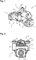
Figure 1 shows a sensor unit according to the invention, in a perspective view; -
Figure 2 shows the sensor unit according toFigure 1 , in a front view; -
Figure 3 shows the sensor unit according toFigure 1 , wherein a plug element is inserted in a plug connection of the sensor housing; -
Figure 4 shows a perspective overhead view of the sensor unit according toFigure 1 ; -
Figure 5 shows an underside view of the sensor unit according toFigure 1 ; -
Figure 6 shows a sectional view along plane VI-VI inFigure 5 ; -
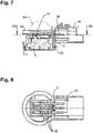
Figure 7 shows a sectional view of the sensor housing of the sensor unit according toFigure 1 ; -
Figure 8 shows a sectional view along plane VIII-VIII inFigure 7 ; -
Figure 9 shows an underside view of part of the sensor housing of the sensor unit according toFigure 7 ; -
Figure 10 shows a sectional view along plane X-X inFigure 9 ; -
Figure 11 shows a view corresponding to that represented inFigure 9 , wherein a sensor element is inserted in the sensor housing; -
Figure 12 shows a sectional view along plane XII-XII inFigure 11 ; and -
Figure 13 shows a detailed view of section XIII inFigure 7 . - In the figures, a
sensor unit 2 is represented, which comprises ahydraulic housing 4 and asensor housing 6. - The hydraulic housing is designed to be arranged in a hydraulic circuit. The hydraulic circuit, in particular, is a circuit between a transmitter and a receiver, wherein the receiver can be a release cylinder of a clutch, an actuating cylinder for a brake, or a similar component.
- The function of the
sensor housing 6 is the accommodation of asensor element 8, by means of which a parameter of the hydraulic fluid in the hydraulic circuit can be detected, in particular pressure and/or temperature. Thesensor element 8, in particular, is a digital sensor. - According to the claimed invention, both the
hydraulic housing 4 and thesensor housing 6 are comprised of plastic. In particular, they are injection-moulded. - The
hydraulic housing 4 comprises afluid inlet 10 and afluid outlet 12, both of which are configured as quick couplings. The term "quick coupling" signifies that a plug element of a hydraulic line can be connected to thefluid inlet 10 or thefluid outlet 12 in a pressure-tight and leakage-free manner, without the necessity of a tool for this purpose, and that this connection can also be released thereafter, without the use of a tool. - In the exemplary embodiment represented, the
fluid inlet 10 and thefluid outlet 12 are configured as sockets, to each of which alocking clamp 14 is assigned. Thelocking clamp 14 can latch into a slot or a similar structure of the plug element of the hydraulic line, and can also release the latter, when the locking clamp is actuated. - A fluid duct extends through the
hydraulic housing 4 between thefluid inlet 10 and thefluid outlet 12, through which the hydraulic fluid can flow, in the hydraulic circuit in which thesensor unit 2 is arranged. - The designations of the quick couplings as an input and an output have been selected here in the interests of clarity only. These are openings in the hydraulic housing through which, depending upon the application and the actuating state, the hydraulic fluid can flow in and flow back out again.
- A
branch 18 taps off from thefluid duct 16, which leads to a measuringchamber 20. Thesensor element 8 is arranged in the measuringchamber 20, such that it is directly exposed to the hydraulic fluid. - A
seal 22, for example an O-ring, is arranged around the opening of thebranch 18 into the measuringchamber 20, which constitutes a seal between thehydraulic housing 4 and thesensor element 8. - The
sensor element 8 is accommodated in a socket-shapedfitting 24 of the sensor housing 6 (c.f. in particularFigures 7 to 12 ). On the outer surface of the socket-shapedfitting 24, aseal 26, for example an O-ring, is arranged, which constitutes a seal against an inner wall of a likewiseannular locator 28, which is configured integrally with thehydraulic housing 4, and the function of which is the accommodation of thesensor housing 6 on thehydraulic housing 4. - In the interior of the socket-shaped
fitting 24, a plurality of latching lugs 30 are arranged, by means of which thesensor element 8 can be pre-fitted in thesensor housing 6. - The
sensor element 8 is provided with apositioning projection 32, which ensures that it can only be fitted in thesensor housing 6 with a predefined orientation. - On the reverse side thereof, i.e. the side which, in the assembled state, is averted from the measuring
chamber 20, thesensor element 8 is provided with a plurality of signal outputs 34, the function of which is the electrical contact connection of thesensor element 8. The term "signal output", in this context, is the overall term for all the electrical connections of thesensor element 8, i.e. both for the supply of electric power and for the transmission of sensor signals. - In the
sensor housing 6, a plurality of electrically conductiveterminal contacts 36 are accommodated, the function of which is to connect thesensor element 8 to a plug element 38 (seeFigure 3 ). Theplug element 38 is plugged into aplug connection 40, which is integrally configured with thesensor housing 6 and constitutes a plug-in chamber for the plug element. In the interior of the plug connection, one end of theterminal contacts 36 is exposed, such that the latter is electrically contact-connected upon the insertion of theplug element 38. - The ends of the
terminal contacts 36, which are positioned in opposition to the end thereof which is arranged in theplug connection 40, are exposed in the interior of the fitting 24. The ends are thus elastically pre-tensioned against the signal outputs 34 of thesensor element 8. This can be achieved, either wherein theterminal contacts 36 themselves sustain appropriate plastic deformation, such that the desired pre-tensioning is achieved, or wherein theterminal contacts 36 are appropriately compressed against thesensor element 8 by a material wedge 42 (seeFigure 13 ), which is integrated in thesensor housing 6. - The
terminal contacts 36 are accommodated in thesensor housing 6 by the press-fitting thereof into appropriate openings, once thesensor housing 6 has been injection-moulded. - Once the
sensor element 8 has been pre-fitted in thesensor housing 6, thesensor housing 6 can be fitted to thehydraulic housing 4. To this end, the fitting 24 thereof is inserted in thelocator 28. For fixing purposes, in the exemplary embodiment represented, thesensor housing 6 comprises two fixinglugs 44, each of which is provided with anopening 46 for a fixingscrew 48. - The fixing screws 48 are screwed into
abutments 50, which are integrally configured with thehydraulic housing 4. - In the exemplary embodiment represented, two
abutments 50 and two fixinglugs 44 are employed, which are arranged in diametrical opposition to one another with respect to the centre line of the fitting 24. Accordingly, there are two possible positions in which thesensor housing 6 can be accommodated relative to thehydraulic housing 4. - It is also conceivable for a total of four abutments to be employed, which are arranged at an angle of 90° to one another. In this case, four orientations of the
sensor housing 6 relative to thehydraulic housing 4 would be possible wherein, in two orientations, the cable outlet runs parallel to thefluid duct 16 and, in two further orientations, is perpendicular thereto.
Claims (11)
- Sensor unit (2) for a hydraulic circuit of a motor vehicle, the sensor unit (2) having a hydraulic housing (4), which comprises a fluid inlet (10), a fluid outlet (12) and a fluid duct (16) between the fluid inlet (10) and the fluid outlet (12), wherein the fluid inlet (10) and the fluid outlet (12) are configured as quick couplings, and having a sensor housing (6) in which a sensor element (8) is accommodated, and which is fitted to the hydraulic housing (4) such that the sensor element (8) is assigned to the fluid duct (16), wherein the sensor housing (6) is detachably mounted on the hydraulic housing (4) and comprises a plug connection (40), into which a plug element (38) can be inserted, by means of which a signal of the sensor element (8) can be transmitted characterized in that the sensor element (8) is a pressure sensor, in which a temperature sensor is also integrated and in that both the hydraulic housing (4) and the sensor housing (6) are comprised of plastic.
- Sensor unit (2) according to Claim 1, characterized in that the quick couplings are configured as sockets.
- Sensor unit (2) according to Claim 1 or Claim 2, characterized in that the quick couplings incorporate a locking clamp (14), by means of which a plug element of a hydraulic line can be locked onto a fluid inlet (10) or fluid outlet (12).
- Sensor unit (2) according to one of the preceding claims, characterized in that a branch (18) from the fluid duct (16) leads to a measuring chamber (20), in which the sensor element (8) is arranged.
- Sensor unit (2) according to Claim 4, characterized in that a seal (22) is arranged between the sensor element (8) and a wall of the measuring chamber (20), which surrounds the opening of the branch (18) into the measuring chamber (20).
- Sensor unit (2) according to one of the preceding claims, characterized in that the sensor element (8) is latched into the sensor housing (6).
- Sensor unit (2) according to one of the preceding claims, characterized in that a plurality of electrically conductive terminal contacts (36) are accommodated in the sensor housing (6), in particular by way of a press-fit arrangement.
- Sensor unit (2) according to Claim 7, characterized in that the terminal contacts (36) engage with the signal outputs (34) of the sensor element (8) in an elastically pre-tensioned arrangement.
- Sensor unit (2) according to one of the preceding claims, characterized in that the sensor housing (6) is screwed to the hydraulic housing (4) in one of a plurality of potential orientations.
- Sensor unit (2) according to one of the preceding claims, characterized in that a seal (26) is provided, which constitutes the seal between the sensor housing (6) and the hydraulic housing (4).
- Sensor unit (2) according to one of the preceding claims, characterized in that the sensor element (8) is a digital sensor.
Applications Claiming Priority (1)
| Application Number | Priority Date | Filing Date | Title |
|---|---|---|---|
| DE102019104873.7A DE102019104873A1 (en) | 2019-02-26 | 2019-02-26 | Sensor assembly for a hydraulic circuit |
Publications (2)
| Publication Number | Publication Date |
|---|---|
| EP3702748A1 EP3702748A1 (en) | 2020-09-02 |
| EP3702748B1 true EP3702748B1 (en) | 2023-01-04 |
Family
ID=69902969
Family Applications (1)
| Application Number | Title | Priority Date | Filing Date |
|---|---|---|---|
| EP20159116.1A Active EP3702748B1 (en) | 2019-02-26 | 2020-02-24 | Sensor unit for a hydraulic circuit |
Country Status (4)
| Country | Link |
|---|---|
| EP (1) | EP3702748B1 (en) |
| KR (1) | KR102766566B1 (en) |
| CN (1) | CN111609965A (en) |
| DE (1) | DE102019104873A1 (en) |
Families Citing this family (1)
| Publication number | Priority date | Publication date | Assignee | Title |
|---|---|---|---|---|
| CN117213695A (en) * | 2023-05-07 | 2023-12-12 | 武汉飞恩微电子有限公司 | Pressure sensor |
Citations (2)
| Publication number | Priority date | Publication date | Assignee | Title |
|---|---|---|---|---|
| SU1492156A1 (en) * | 1987-09-21 | 1989-07-07 | Предприятие П/Я А-1714 | Quick disconnectable plastic tubes joint |
| DE102014222115A1 (en) * | 2014-10-29 | 2016-05-04 | Schaeffler Technologies AG & Co. KG | Actuation system with a flow sensor in the hydraulic line for determining the pedal travel and method for determining the pedal travel / the pedal position |
Family Cites Families (7)
| Publication number | Priority date | Publication date | Assignee | Title |
|---|---|---|---|---|
| DE8714327U1 (en) * | 1987-10-28 | 1987-12-23 | ASYS-GmbH Gesellschaft für die Herstellung und den Vertrieb von Systemen für die Automatisierung, 7060 Schorndorf | Screw connection for pipes and/or hoses |
| US6223766B1 (en) * | 1996-02-20 | 2001-05-01 | Presto-Tap, Llc | Pressure testing apparatus and testing method for propane tank systems |
| AUPQ626400A0 (en) * | 2000-03-17 | 2000-04-15 | Hapsburg, Edmund | Method and device for control of delivery of temperature-sensitive hydrocarbons |
| GB0723205D0 (en) * | 2007-11-27 | 2008-01-09 | Ge Healthcare Bio Sciences Ab | Multi-component part pressure transducer assembley |
| US8944473B2 (en) * | 2010-08-31 | 2015-02-03 | A. Raymond Et Cie | Quick connector with a sensor housing |
| ITUB20154286A1 (en) * | 2015-10-09 | 2017-04-09 | Ip Cleaning S R L | HOT WATER CLEANER WITH TEMPERATURE CONTROL |
| JP6834405B2 (en) * | 2016-11-25 | 2021-02-24 | 日本電産トーソク株式会社 | Hydraulic sensor mounting structure |
-
2019
- 2019-02-26 DE DE102019104873.7A patent/DE102019104873A1/en not_active Withdrawn
-
2020
- 2020-02-24 EP EP20159116.1A patent/EP3702748B1/en active Active
- 2020-02-25 KR KR1020200022875A patent/KR102766566B1/en active Active
- 2020-02-26 CN CN202010118771.6A patent/CN111609965A/en active Pending
Patent Citations (2)
| Publication number | Priority date | Publication date | Assignee | Title |
|---|---|---|---|---|
| SU1492156A1 (en) * | 1987-09-21 | 1989-07-07 | Предприятие П/Я А-1714 | Quick disconnectable plastic tubes joint |
| DE102014222115A1 (en) * | 2014-10-29 | 2016-05-04 | Schaeffler Technologies AG & Co. KG | Actuation system with a flow sensor in the hydraulic line for determining the pedal travel and method for determining the pedal travel / the pedal position |
Also Published As
| Publication number | Publication date |
|---|---|
| EP3702748A1 (en) | 2020-09-02 |
| DE102019104873A1 (en) | 2020-08-27 |
| KR102766566B1 (en) | 2025-02-13 |
| KR20200104246A (en) | 2020-09-03 |
| CN111609965A (en) | 2020-09-01 |
Similar Documents
| Publication | Publication Date | Title |
|---|---|---|
| CN110562229A (en) | Electromechanical brake connector | |
| US8278790B2 (en) | Combined frequency converter and electric motor having converter housing connected to motor housing via adapter | |
| EP1774621B1 (en) | Connecting arrangement and contact pin | |
| CA2725710C (en) | Device for measuring fluid properties in caustic environments | |
| CN101710662B (en) | Connector assembly with plurality of discrete components | |
| JP6505229B2 (en) | Sensor device, in particular for use in a motor vehicle | |
| AU2999097A (en) | Locking sensor cartridge with integral fluid ports, electrical connections, and pump tube | |
| US20240372304A1 (en) | Connector | |
| CN113287231A (en) | Plug connector part with a connector part connected to a housing part | |
| WO2007106749A2 (en) | Fluid quick connector with integrated pressure sensor | |
| US20030032321A1 (en) | Sealed connector | |
| GB2480511A (en) | Multifunction Plug Connector Of An Oil Pan Of A Vehicle | |
| JP2009523301A (en) | Connection adapter for sensor or actuator | |
| US12244913B2 (en) | Connection device for an electric and/or electronic appliance with an appliance housing, as well as appliance housing assembly and sensor assembly | |
| EP3702748A1 (en) | Sensor unit for a hydraulic circuit | |
| US20110273854A1 (en) | Magnetic Field Sensor | |
| JP2010212136A (en) | Joint connector | |
| CN120641724A (en) | Sensor components for vehicles | |
| CN105628286B (en) | Pressure sensor | |
| US10107694B2 (en) | Sensor arrangement, sensor arrangement system and set of sensor arrangement elements | |
| JP7819239B2 (en) | Hybrid connector housing parts | |
| US6540565B2 (en) | Coupling or plug for a connector for use in metrology, specifically in environmental metrology | |
| US20070049111A1 (en) | Electrical plug-and-socket connector | |
| US5697283A (en) | Electronically controllable brake booster with a cable feed-through | |
| US20040121637A1 (en) | Socket connecting system for connecting electrical conductors |
Legal Events
| Date | Code | Title | Description |
|---|---|---|---|
| PUAI | Public reference made under article 153(3) epc to a published international application that has entered the european phase |
Free format text: ORIGINAL CODE: 0009012 |
|
| STAA | Information on the status of an ep patent application or granted ep patent |
Free format text: STATUS: REQUEST FOR EXAMINATION WAS MADE |
|
| 17P | Request for examination filed |
Effective date: 20200224 |
|
| AK | Designated contracting states |
Kind code of ref document: A1 Designated state(s): AL AT BE BG CH CY CZ DE DK EE ES FI FR GB GR HR HU IE IS IT LI LT LU LV MC MK MT NL NO PL PT RO RS SE SI SK SM TR |
|
| AX | Request for extension of the european patent |
Extension state: BA ME |
|
| STAA | Information on the status of an ep patent application or granted ep patent |
Free format text: STATUS: EXAMINATION IS IN PROGRESS |
|
| 17Q | First examination report despatched |
Effective date: 20210428 |
|
| GRAP | Despatch of communication of intention to grant a patent |
Free format text: ORIGINAL CODE: EPIDOSNIGR1 |
|
| STAA | Information on the status of an ep patent application or granted ep patent |
Free format text: STATUS: GRANT OF PATENT IS INTENDED |
|
| GRAS | Grant fee paid |
Free format text: ORIGINAL CODE: EPIDOSNIGR3 |
|
| INTG | Intention to grant announced |
Effective date: 20221102 |
|
| GRAA | (expected) grant |
Free format text: ORIGINAL CODE: 0009210 |
|
| STAA | Information on the status of an ep patent application or granted ep patent |
Free format text: STATUS: THE PATENT HAS BEEN GRANTED |
|
| AK | Designated contracting states |
Kind code of ref document: B1 Designated state(s): AL AT BE BG CH CY CZ DE DK EE ES FI FR GB GR HR HU IE IS IT LI LT LU LV MC MK MT NL NO PL PT RO RS SE SI SK SM TR |
|
| REG | Reference to a national code |
Ref country code: GB Ref legal event code: FG4D |
|
| REG | Reference to a national code |
Ref country code: CH Ref legal event code: EP |
|
| REG | Reference to a national code |
Ref country code: AT Ref legal event code: REF Ref document number: 1542253 Country of ref document: AT Kind code of ref document: T Effective date: 20230115 |
|
| REG | Reference to a national code |
Ref country code: DE Ref legal event code: R096 Ref document number: 602020007274 Country of ref document: DE |
|
| REG | Reference to a national code |
Ref country code: IE Ref legal event code: FG4D |
|
| REG | Reference to a national code |
Ref country code: LT Ref legal event code: MG9D |
|
| REG | Reference to a national code |
Ref country code: NL Ref legal event code: MP Effective date: 20230104 |
|
| REG | Reference to a national code |
Ref country code: AT Ref legal event code: MK05 Ref document number: 1542253 Country of ref document: AT Kind code of ref document: T Effective date: 20230104 |
|
| PG25 | Lapsed in a contracting state [announced via postgrant information from national office to epo] |
Ref country code: NL Free format text: LAPSE BECAUSE OF FAILURE TO SUBMIT A TRANSLATION OF THE DESCRIPTION OR TO PAY THE FEE WITHIN THE PRESCRIBED TIME-LIMIT Effective date: 20230104 |
|
| PG25 | Lapsed in a contracting state [announced via postgrant information from national office to epo] |
Ref country code: RS Free format text: LAPSE BECAUSE OF FAILURE TO SUBMIT A TRANSLATION OF THE DESCRIPTION OR TO PAY THE FEE WITHIN THE PRESCRIBED TIME-LIMIT Effective date: 20230104 Ref country code: PT Free format text: LAPSE BECAUSE OF FAILURE TO SUBMIT A TRANSLATION OF THE DESCRIPTION OR TO PAY THE FEE WITHIN THE PRESCRIBED TIME-LIMIT Effective date: 20230504 Ref country code: NO Free format text: LAPSE BECAUSE OF FAILURE TO SUBMIT A TRANSLATION OF THE DESCRIPTION OR TO PAY THE FEE WITHIN THE PRESCRIBED TIME-LIMIT Effective date: 20230404 Ref country code: LV Free format text: LAPSE BECAUSE OF FAILURE TO SUBMIT A TRANSLATION OF THE DESCRIPTION OR TO PAY THE FEE WITHIN THE PRESCRIBED TIME-LIMIT Effective date: 20230104 Ref country code: LT Free format text: LAPSE BECAUSE OF FAILURE TO SUBMIT A TRANSLATION OF THE DESCRIPTION OR TO PAY THE FEE WITHIN THE PRESCRIBED TIME-LIMIT Effective date: 20230104 Ref country code: HR Free format text: LAPSE BECAUSE OF FAILURE TO SUBMIT A TRANSLATION OF THE DESCRIPTION OR TO PAY THE FEE WITHIN THE PRESCRIBED TIME-LIMIT Effective date: 20230104 Ref country code: ES Free format text: LAPSE BECAUSE OF FAILURE TO SUBMIT A TRANSLATION OF THE DESCRIPTION OR TO PAY THE FEE WITHIN THE PRESCRIBED TIME-LIMIT Effective date: 20230104 Ref country code: AT Free format text: LAPSE BECAUSE OF FAILURE TO SUBMIT A TRANSLATION OF THE DESCRIPTION OR TO PAY THE FEE WITHIN THE PRESCRIBED TIME-LIMIT Effective date: 20230104 |
|
| P01 | Opt-out of the competence of the unified patent court (upc) registered |
Effective date: 20230629 |
|
| PG25 | Lapsed in a contracting state [announced via postgrant information from national office to epo] |
Ref country code: SE Free format text: LAPSE BECAUSE OF FAILURE TO SUBMIT A TRANSLATION OF THE DESCRIPTION OR TO PAY THE FEE WITHIN THE PRESCRIBED TIME-LIMIT Effective date: 20230104 Ref country code: PL Free format text: LAPSE BECAUSE OF FAILURE TO SUBMIT A TRANSLATION OF THE DESCRIPTION OR TO PAY THE FEE WITHIN THE PRESCRIBED TIME-LIMIT Effective date: 20230104 Ref country code: IS Free format text: LAPSE BECAUSE OF FAILURE TO SUBMIT A TRANSLATION OF THE DESCRIPTION OR TO PAY THE FEE WITHIN THE PRESCRIBED TIME-LIMIT Effective date: 20230504 Ref country code: GR Free format text: LAPSE BECAUSE OF FAILURE TO SUBMIT A TRANSLATION OF THE DESCRIPTION OR TO PAY THE FEE WITHIN THE PRESCRIBED TIME-LIMIT Effective date: 20230405 Ref country code: FI Free format text: LAPSE BECAUSE OF FAILURE TO SUBMIT A TRANSLATION OF THE DESCRIPTION OR TO PAY THE FEE WITHIN THE PRESCRIBED TIME-LIMIT Effective date: 20230104 |
|
| REG | Reference to a national code |
Ref country code: CH Ref legal event code: PL |
|
| REG | Reference to a national code |
Ref country code: DE Ref legal event code: R097 Ref document number: 602020007274 Country of ref document: DE |
|
| REG | Reference to a national code |
Ref country code: BE Ref legal event code: MM Effective date: 20230228 |
|
| PG25 | Lapsed in a contracting state [announced via postgrant information from national office to epo] |
Ref country code: SM Free format text: LAPSE BECAUSE OF FAILURE TO SUBMIT A TRANSLATION OF THE DESCRIPTION OR TO PAY THE FEE WITHIN THE PRESCRIBED TIME-LIMIT Effective date: 20230104 Ref country code: RO Free format text: LAPSE BECAUSE OF FAILURE TO SUBMIT A TRANSLATION OF THE DESCRIPTION OR TO PAY THE FEE WITHIN THE PRESCRIBED TIME-LIMIT Effective date: 20230104 Ref country code: MC Free format text: LAPSE BECAUSE OF FAILURE TO SUBMIT A TRANSLATION OF THE DESCRIPTION OR TO PAY THE FEE WITHIN THE PRESCRIBED TIME-LIMIT Effective date: 20230104 Ref country code: LU Free format text: LAPSE BECAUSE OF NON-PAYMENT OF DUE FEES Effective date: 20230224 Ref country code: LI Free format text: LAPSE BECAUSE OF NON-PAYMENT OF DUE FEES Effective date: 20230228 Ref country code: EE Free format text: LAPSE BECAUSE OF FAILURE TO SUBMIT A TRANSLATION OF THE DESCRIPTION OR TO PAY THE FEE WITHIN THE PRESCRIBED TIME-LIMIT Effective date: 20230104 Ref country code: DK Free format text: LAPSE BECAUSE OF FAILURE TO SUBMIT A TRANSLATION OF THE DESCRIPTION OR TO PAY THE FEE WITHIN THE PRESCRIBED TIME-LIMIT Effective date: 20230104 Ref country code: CZ Free format text: LAPSE BECAUSE OF FAILURE TO SUBMIT A TRANSLATION OF THE DESCRIPTION OR TO PAY THE FEE WITHIN THE PRESCRIBED TIME-LIMIT Effective date: 20230104 Ref country code: CH Free format text: LAPSE BECAUSE OF NON-PAYMENT OF DUE FEES Effective date: 20230228 |
|
| PLBE | No opposition filed within time limit |
Free format text: ORIGINAL CODE: 0009261 |
|
| STAA | Information on the status of an ep patent application or granted ep patent |
Free format text: STATUS: NO OPPOSITION FILED WITHIN TIME LIMIT |
|
| PG25 | Lapsed in a contracting state [announced via postgrant information from national office to epo] |
Ref country code: SK Free format text: LAPSE BECAUSE OF FAILURE TO SUBMIT A TRANSLATION OF THE DESCRIPTION OR TO PAY THE FEE WITHIN THE PRESCRIBED TIME-LIMIT Effective date: 20230104 |
|
| 26N | No opposition filed |
Effective date: 20231005 |
|
| REG | Reference to a national code |
Ref country code: IE Ref legal event code: MM4A |
|
| PG25 | Lapsed in a contracting state [announced via postgrant information from national office to epo] |
Ref country code: SI Free format text: LAPSE BECAUSE OF FAILURE TO SUBMIT A TRANSLATION OF THE DESCRIPTION OR TO PAY THE FEE WITHIN THE PRESCRIBED TIME-LIMIT Effective date: 20230104 Ref country code: IE Free format text: LAPSE BECAUSE OF NON-PAYMENT OF DUE FEES Effective date: 20230224 |
|
| PG25 | Lapsed in a contracting state [announced via postgrant information from national office to epo] |
Ref country code: BE Free format text: LAPSE BECAUSE OF NON-PAYMENT OF DUE FEES Effective date: 20230228 |
|
| PG25 | Lapsed in a contracting state [announced via postgrant information from national office to epo] |
Ref country code: IT Free format text: LAPSE BECAUSE OF FAILURE TO SUBMIT A TRANSLATION OF THE DESCRIPTION OR TO PAY THE FEE WITHIN THE PRESCRIBED TIME-LIMIT Effective date: 20230104 |
|
| GBPC | Gb: european patent ceased through non-payment of renewal fee |
Effective date: 20240224 |
|
| PG25 | Lapsed in a contracting state [announced via postgrant information from national office to epo] |
Ref country code: BG Free format text: LAPSE BECAUSE OF FAILURE TO SUBMIT A TRANSLATION OF THE DESCRIPTION OR TO PAY THE FEE WITHIN THE PRESCRIBED TIME-LIMIT Effective date: 20230104 |
|
| PG25 | Lapsed in a contracting state [announced via postgrant information from national office to epo] |
Ref country code: BG Free format text: LAPSE BECAUSE OF FAILURE TO SUBMIT A TRANSLATION OF THE DESCRIPTION OR TO PAY THE FEE WITHIN THE PRESCRIBED TIME-LIMIT Effective date: 20230104 |
|
| PG25 | Lapsed in a contracting state [announced via postgrant information from national office to epo] |
Ref country code: GB Free format text: LAPSE BECAUSE OF NON-PAYMENT OF DUE FEES Effective date: 20240224 |
|
| PG25 | Lapsed in a contracting state [announced via postgrant information from national office to epo] |
Ref country code: GB Free format text: LAPSE BECAUSE OF NON-PAYMENT OF DUE FEES Effective date: 20240224 |
|
| PG25 | Lapsed in a contracting state [announced via postgrant information from national office to epo] |
Ref country code: CY Free format text: LAPSE BECAUSE OF FAILURE TO SUBMIT A TRANSLATION OF THE DESCRIPTION OR TO PAY THE FEE WITHIN THE PRESCRIBED TIME-LIMIT; INVALID AB INITIO Effective date: 20200224 |
|
| PG25 | Lapsed in a contracting state [announced via postgrant information from national office to epo] |
Ref country code: HU Free format text: LAPSE BECAUSE OF FAILURE TO SUBMIT A TRANSLATION OF THE DESCRIPTION OR TO PAY THE FEE WITHIN THE PRESCRIBED TIME-LIMIT; INVALID AB INITIO Effective date: 20200224 |
|
| PG25 | Lapsed in a contracting state [announced via postgrant information from national office to epo] |
Ref country code: TR Free format text: LAPSE BECAUSE OF FAILURE TO SUBMIT A TRANSLATION OF THE DESCRIPTION OR TO PAY THE FEE WITHIN THE PRESCRIBED TIME-LIMIT Effective date: 20230104 |
|
| PGFP | Annual fee paid to national office [announced via postgrant information from national office to epo] |
Ref country code: DE Payment date: 20260206 Year of fee payment: 7 |
|
| PGFP | Annual fee paid to national office [announced via postgrant information from national office to epo] |
Ref country code: FR Payment date: 20260227 Year of fee payment: 7 |