EP3702623A1 - Fan assembly for computer chassis and computer system - Google Patents
Fan assembly for computer chassis and computer system Download PDFInfo
- Publication number
- EP3702623A1 EP3702623A1 EP19187774.5A EP19187774A EP3702623A1 EP 3702623 A1 EP3702623 A1 EP 3702623A1 EP 19187774 A EP19187774 A EP 19187774A EP 3702623 A1 EP3702623 A1 EP 3702623A1
- Authority
- EP
- European Patent Office
- Prior art keywords
- slats
- bars
- received
- airflow
- bar
- Prior art date
- Legal status (The legal status is an assumption and is not a legal conclusion. Google has not performed a legal analysis and makes no representation as to the accuracy of the status listed.)
- Granted
Links
Images

Classifications
-
- F—MECHANICAL ENGINEERING; LIGHTING; HEATING; WEAPONS; BLASTING
- F04—POSITIVE - DISPLACEMENT MACHINES FOR LIQUIDS; PUMPS FOR LIQUIDS OR ELASTIC FLUIDS
- F04D—NON-POSITIVE-DISPLACEMENT PUMPS
- F04D29/00—Details, component parts, or accessories
- F04D29/40—Casings; Connections of working fluid
- F04D29/52—Casings; Connections of working fluid for axial pumps
- F04D29/54—Fluid-guiding means, e.g. diffusers
- F04D29/56—Fluid-guiding means, e.g. diffusers adjustable
- F04D29/563—Fluid-guiding means, e.g. diffusers adjustable specially adapted for elastic fluid pumps
-
- H—ELECTRICITY
- H05—ELECTRIC TECHNIQUES NOT OTHERWISE PROVIDED FOR
- H05K—PRINTED CIRCUITS; CASINGS OR CONSTRUCTIONAL DETAILS OF ELECTRIC APPARATUS; MANUFACTURE OF ASSEMBLAGES OF ELECTRICAL COMPONENTS
- H05K7/00—Constructional details common to different types of electric apparatus
- H05K7/20—Modifications to facilitate cooling, ventilating, or heating
- H05K7/20009—Modifications to facilitate cooling, ventilating, or heating using a gaseous coolant in electronic enclosures
- H05K7/20136—Forced ventilation, e.g. by fans
- H05K7/20181—Filters; Louvers
-
- G—PHYSICS
- G06—COMPUTING OR CALCULATING; COUNTING
- G06F—ELECTRIC DIGITAL DATA PROCESSING
- G06F1/00—Details not covered by groups G06F3/00 - G06F13/00 and G06F21/00
- G06F1/16—Constructional details or arrangements
- G06F1/20—Cooling means
-
- F—MECHANICAL ENGINEERING; LIGHTING; HEATING; WEAPONS; BLASTING
- F04—POSITIVE - DISPLACEMENT MACHINES FOR LIQUIDS; PUMPS FOR LIQUIDS OR ELASTIC FLUIDS
- F04D—NON-POSITIVE-DISPLACEMENT PUMPS
- F04D25/00—Pumping installations or systems
- F04D25/02—Units comprising pumps and their driving means
- F04D25/08—Units comprising pumps and their driving means the working fluid being air, e.g. for ventilation
- F04D25/12—Units comprising pumps and their driving means the working fluid being air, e.g. for ventilation the unit being adapted for mounting in apertures
- F04D25/14—Units comprising pumps and their driving means the working fluid being air, e.g. for ventilation the unit being adapted for mounting in apertures and having shutters, e.g. automatically closed when not in use
-
- F—MECHANICAL ENGINEERING; LIGHTING; HEATING; WEAPONS; BLASTING
- F04—POSITIVE - DISPLACEMENT MACHINES FOR LIQUIDS; PUMPS FOR LIQUIDS OR ELASTIC FLUIDS
- F04D—NON-POSITIVE-DISPLACEMENT PUMPS
- F04D25/00—Pumping installations or systems
- F04D25/16—Combinations of two or more pumps ; Producing two or more separate gas flows
- F04D25/166—Combinations of two or more pumps ; Producing two or more separate gas flows using fans
-
- G—PHYSICS
- G06—COMPUTING OR CALCULATING; COUNTING
- G06F—ELECTRIC DIGITAL DATA PROCESSING
- G06F1/00—Details not covered by groups G06F3/00 - G06F13/00 and G06F21/00
- G06F1/16—Constructional details or arrangements
- G06F1/18—Packaging or power distribution
- G06F1/183—Internal mounting support structures, e.g. for supporting printed circuit boards
-
- H—ELECTRICITY
- H05—ELECTRIC TECHNIQUES NOT OTHERWISE PROVIDED FOR
- H05K—PRINTED CIRCUITS; CASINGS OR CONSTRUCTIONAL DETAILS OF ELECTRIC APPARATUS; MANUFACTURE OF ASSEMBLAGES OF ELECTRICAL COMPONENTS
- H05K7/00—Constructional details common to different types of electric apparatus
- H05K7/20—Modifications to facilitate cooling, ventilating, or heating
- H05K7/20009—Modifications to facilitate cooling, ventilating, or heating using a gaseous coolant in electronic enclosures
- H05K7/20136—Forced ventilation, e.g. by fans
- H05K7/20172—Fan mounting or fan specifications
-
- H—ELECTRICITY
- H05—ELECTRIC TECHNIQUES NOT OTHERWISE PROVIDED FOR
- H05K—PRINTED CIRCUITS; CASINGS OR CONSTRUCTIONAL DETAILS OF ELECTRIC APPARATUS; MANUFACTURE OF ASSEMBLAGES OF ELECTRICAL COMPONENTS
- H05K7/00—Constructional details common to different types of electric apparatus
- H05K7/20—Modifications to facilitate cooling, ventilating, or heating
- H05K7/20709—Modifications to facilitate cooling, ventilating, or heating for server racks or cabinets; for data centers, e.g. 19-inch computer racks
- H05K7/20718—Forced ventilation of a gaseous coolant
- H05K7/20727—Forced ventilation of a gaseous coolant within server blades for removing heat from heat source
-
- G—PHYSICS
- G06—COMPUTING OR CALCULATING; COUNTING
- G06F—ELECTRIC DIGITAL DATA PROCESSING
- G06F2200/00—Indexing scheme relating to G06F1/04 - G06F1/32
- G06F2200/20—Indexing scheme relating to G06F1/20
- G06F2200/201—Cooling arrangements using cooling fluid
Definitions
- the present disclosure relates to an adjustable apparatus for a computer fan.
- Computer components produce heat, which in turn increases the ambient temperature in a computer system. Increased ambient temperature can damage computer components, and cause failure of the computer system.
- a cooling fan is typically used in a system to control the ambient temperature of the system, and to direct airflow.
- Conventional computer systems have an array of cooling fans, each fan pointing at different components. When properly operating, the cooling fans can provide balanced airflow over a chassis body. However, if one cooling fan fails, the air intake of the remaining cooling fans can draw air backwards through the failed fan. This disrupts the airflow through the computer chassis because some of the airflow is now reversed. This inverse airflow prevents the remaining cooling fans from properly cooling the chassis. As a result, heat is increased in the chassis body, which can eventually cause damage to the computer components. Therefore, systems are needed to ensure proper airflow through a computer system even when a fan fails.
- the apparatus includes a plurality of bars, a plurality of slats, a knob, and at least one pin.
- Each slat in the plurality of slats is pivotably coupled to a bar in the plurality of bars.
- a first pair of bars in the plurality of bars has an option on each bar. The knob is received at this option so that rotating movements of the knob cause the apparatus to adjust between a plurality of positions.
- a pin is coupled to one of the plurality of bars. The pin secures the apparatus to a cooling fan in a cooling system.
- the apparatus has multiple pins corresponding to multiple cooling fans in the computer system.
- Each pin includes a male connector configured to be received at an indented portion of the cooling fan.
- the indented portion can be an option or an opening.
- a position of the pin in the cooling fan locks the apparatus in one position of the plurality of positions.
- the apparatus can be locked in (1) a first position to allow airflow intake but not airflow exhaust, or (2) a second position to allow airflow exhaust but not airflow intake.
- the first pair of bars is located at a top portion of the apparatus, and a second pair of bars is located at a bottom portion of the apparatus.
- Each bar can have a plurality of indented portions. Each indented portion corresponds to a slat in the plurality of slats.
- the plurality of indented portions configures the plurality of slats to pivot in a first direction (allowing air intake) and not in a second direction (preventing air exhaust).
- the slats can pivot in the first direction upon receiving airflow in the first direction.
- the slats lie adjacent to neighboring slats in the plurality of slats. Therefore, airflow from the second direction is prevented from entering the apparatus.
- the first direction is opposite the second direction.
- the plurality of indented portions configures the plurality of slats to pivot in the second direction (allowing air exhaust) and not the first direction (preventing air intake).
- the slats pivot in the second direction upon receiving airflow in the second direction.
- the slats lie adjacent to neighboring slats in the plurality of slats. Therefore, airflow from the first direction is prevented from entering the apparatus.
- a second embodiment of the present disclosure provides for a fan assembly for a computer chassis.
- the fan assembly includes a plurality of fans, a frame, and an apparatus configured to be received by the frame.
- the plurality of fans can be configured to be received in the computer chassis.
- the frame can correspond to the plurality of fans, and can receive the apparatus.
- the apparatus can be as provided for with respect to the first embodiment. Additional examples of the second embodiment can be as provided for with respect to the first embodiment.
- a third embodiment of the present disclosure provides a fan assembly for a computer system.
- the fan assembly includes a fan, a frame corresponding to the fan, and an apparatus.
- the apparatus can be received by the frame.
- the apparatus and additional examples of the third embodiment can be provided for as in the first embodiment.
- the present disclosure provides an apparatus for a computer system.
- the apparatus comprises a plurality of bars, a plurality of slats, a knob, and at least one pin.
- the at least one pin can be received at an opening in a cooling fan so that the apparatus is housed adjacent to the cooling fan.
- multiple pins are received at multiple cooling fans in a computer system.
- Each slat of the plurality of slats pivotably couples to at least one bar in the plurality of bars.
- the slats correspond to the cooling fans, and direct airflow towards the cooling fans.
- the knob is located at an option on each bar of a pair of bars. Rotating movements of the knob adjust the apparatus between a plurality of positions.
- the knob can adjust the apparatus such that the slats prevent air flowing through the cooling fans in an inverse direction.
- the disclosed apparatus automatically restricts air flowing in an inverse direction through a failed cooling fan.
- the computing components in a computer system are efficiently and effectively cooled, thereby preventing overheating and malfunction of the computing components.
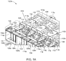
- FIG. 1A shows a system 100A, according to an embodiment of the present disclosure.
- System 100A includes a frame 102; separators 104a, 104b, 104c; slats 106a, 106b, 106c ... 106n; pins 108; male connectors 110; cooling fans 112a, 112b, 112c, and 112d; cooling fan opening 113a, 113b, 113c, and 113d; bars 114a and 114b; a knob 116; and an apparatus 130
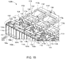
- FIG. 1B shows a system 100B, which includes similar components and labels to system 100A of FIG. 1A .
- FIGs. 1A-1B show similar features of an apparatus for a computer fan, and the features will be discussed in tandem below.
- systems 100A and 100B can be fan assemblies for a computer chassis or a computer system, as readily contemplated by one skilled in the art.
- An apparatus 130 is configured to be received by a plurality of cooling fans (for example, cooling fans 112a, 112b, 112c, and 112d of FIG. 1A or cooling fans 112e, 112f, 112g, and 112h of FIG. 1B ).
- apparatus 130 is shown to correspond to four cooling fans 112, apparatus 130 can be sized shorter or longer to correspond to any number of cooling fans. In some examples, apparatus 130 can correspond to a single cooling fan.
- Apparatus 130 and any corresponding cooling fans 112a, 112b, 112c, and 112d can be received in a computer chassis (not pictured).
- Apparatus 130 includes a plurality of slats 106a, 106b, 106c ... 106n and separators 104a, 104b, 104c.
- Each separator 104a, 104b, 104c can correspond to a division between two cooling fans (for example, separator 104b corresponds to a division between cooling fan 112a and 112b).
- the separators 104a, 104b, and 104c can be connected together via a separator housing 105.
- the separators 104a, 104b, and 104c additionally form barriers between sets of slats in the plurality of slats 106a, 106b, 106c ... 106n.
- a set of slats in the plurality of slats 106a, 106b, 106c ... 106n can correspond to one cooling fan 112a, 112b, 112c, or 112d.
- slats 106a, 106b, and 106c correspond to cooling fan 112a.
- three slats 106a, 106b, and 106c are shown corresponding to each cooling fan 112a, 112b, 112c, and 112d in FIG. 1A , any number of slats can correspond to each cooling fan, as long as there is at least one slat for each fan.
- the slats 106a, 106b, 106c ... 106n can be coupled to the apparatus 130 via bars 114a and 114b, which are at a top portion 134 of the apparatus 130.
- the bars 114a and 114b can have corresponding bars along a bottom portion 133 of the apparatus 130 (not pictured). In some examples, the bottom portion 133 can be the separator housing 105 without any bars.
- Each bar 114a and 114b can have an option (shown further in FIG. 2 ) to receive a knob 116.
- the knob 116 can have an end portion 116a corresponding to the bar 114a, and an end portion 116b corresponding to the bar 114b.
- the knob 116 can rotate clockwise or counterclockwise. Clockwise movement is shown in FIG. 1A , and counter-clockwise movement is shown in FIG. 1B . Additional movement of the bars 114a and 114b and the knob 116 is discussed further below with respect to FIG. 2 and 3A-3D
- Apparatus 130 can include a pin 108 for each cooling fan (for example, cooling fans 112a, 112b, 112c, and 112d in system 100A or cooling fans 112e, 112f, 112g, and 112h in system 100B).
- Each pin 108 is coupled to the bar 114b along a top portion of the apparatus 130.
- the pins 108 can be connected to the separator housing 105 or the frame 102.
- each pin 108 includes a male connector 110 at an edge of the pin 108 to be received at a cooling fan 112a, 112b, 112c, or 112d.
- the male connector 110 can slide into an opening 113a of a corresponding cooling fan 112a.
- a location of opening 113a, 113b, 113c, and 113d in a cooling fan 112a, 112b, 112c, and 112d can correspond to a type of the cooling fan.
- each cooling fan 112a, 112b, 112c, and 112d has an opening 113a, 113b, 113c, and 113d at a right side of the cooling fan.
- each cooling fan 112e, 112f, 112g, and 112h has an opening 113e, 113f, 113g, and 113h at a left side of the cooling fan.
- FIG. 1A correspond to air intake fans, where air flows from an exterior side 131 of the apparatus 130 towards an interior side 132.
- the cooling fans 112e, 112f, 112g, and 112h of FIG. 1B correspond to air exhaust fans where air flows from an interior side 132 of the apparatus 130 towards an exterior side 131.
- FIG. 2 shows an exemplary view 200 of a portion of the apparatus 130.
- FIG. 2 has similar elements and labels as FIGs. 1A-1B , and additionally includes an option 223 on the bar 114a and an option 220 on the bar 114b.
- FIG. 2 demonstrates that rotation of the knob 116 causes the bars 114a and 114b to slide right and left, corresponding to the rotation of the knob 116. For example, if knob 116 is rotated counter-clockwise, an end portion 116b of the knob 116 will push against an edge 221 of the option 220 while end portion 116a pushes against an edge 224 of the option 223. This, in turn, causes the bar 114b to move towards the left, and the bar 114a to move towards the right. Because the slats 106 are coupled to the bars 114a and 114b, movement of the bars 114a and 114b changes an orientation of the slats 106 (as discussed further below with respect to FIGs. 3A-3D ).
- the knob 116 can configure the disclosed apparatus to adjust between a plurality of positions.
- the knob 116 can configure the apparatus in a first position, where the bar 114b is slid entirely to the right, and the bar 114a is slid entirely to the left. This position allows pins 108 to connect with openings 113a, 113b, 113c, and 113d of air intake fans 112a, 112b, 112c, and 112d (as shown in FIG. 1A ).
- the knob 116 can also configure the apparatus in a second position, where the bar 114b is slid entirely to the left and the bar 114a is slid entirely to the right. This position allows pins 108 to connect with openings 113e, 113f, 113g, and 113h of air exhaust fans 112e, 112f, 112g, and 112h (as shown in FIG. 1B ).
- the pins 108 ensure that the apparatus 130 is in the proper position according to the type of fan. Because openings 113 on each fan 112 are in different places for air intake fans 112a, 112b, 112c, and 112d (openings 113a, 113b, 113c, and 113d are on the right) than for air exhaust fans 112e, 112f, 112g, and 112h (openings 113e, 113f, 113g, and 113h are on the left), the apparatus 130 has to be appropriately positioned when received by the cooling fans 112.
- the pins 108 serve as a foolproof mechanism to ensure that the apparatus 130 is properly positioned.
- the pins 108 can lock the apparatus 130 in the proper position when the apparatus 130 is received at cooling fans.
- the knob 116 can position the bars 114a and 114b (and, accordingly, the slats 106 as discussed below) in any interim position between a first position as shown in FIG. 1A and a second position as shown in FIG. 1B .
- FIGs. 3A-3D show the positioning of the bars 114a and 114b, and therefore of the slats 106, in response to a first position and second position of the knob 116.
- FIGs. 3A-3D include similar components and labels to systems 100A, 100B, and apparatus 130 of FIGs. 1A , 1B , and 2 , respectively.
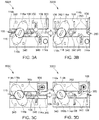
- FIGs. 3A-3D include a plurality of indented portions 340 and a plurality of indented portions 350.
- FIGs. 3A-3B show an exemplary apparatus 300A, 300B configured for air intake, according to an embodiment of the present disclosure.
- a plurality of indented portions 340 and 350 configures the plurality of slats 106 to pivot in a first direction towards the bar 114b (allowing air intake), and not a second direction towards the bar 114a (preventing air exhaust).
- the slats 106 can be pivotably coupled at location 360 to the indented portions 340, 350, or to the separator housing 105 (not pictured).
- FIG. 3A shows a configuration of the apparatus 300A where the slats 106 are stopped from rotating towards the indented portions 340.
- FIG. 3B shows that slats 106 can rotate towards the indented portions 350.
- FIGs. 3A-3B show that when the knob 116 is rotated clockwise in the first position (or when pins 108 are received by air intake fans), the slats 106 pivot towards the indented portions 350 upon receiving airflow towards the indented portions 350.
- FIG. 3A shows that when either no airflow is received towards the indented portions 350 or when airflow is received towards the indented portions 340, the slats 106 lie adjacent to neighboring slats 106.
- FIGs. 3C-3D shows an exemplary apparatus 300C, 300D configured for air exhaust, according to an embodiment of the present disclosure.
- the plurality of indented portions 340 and 350 configures the plurality of slats 106 to pivot in a second direction towards the bar 114a (allowing air exhaust) and not a first direction towards the bar 114b (preventing air intake).
- FIG. 3C shows when the slats 106 are stopped from rotating towards the indented portions 350.
- FIG. 3D shows that slats 106 can rotate towards the indented portions 340.
- FIGS. 3C and 3D show that when the knob 116 is rotated counter-clockwise in the second position (or when pins 108 are received by air exhaust fans), the slats 106 pivot towards indented portions 340 upon receiving airflow towards the indented portions 340.
- FIG. 3C shows that when either no airflow is received towards the indented portions 340 or when airflow is received towards indented portions 350, the slats 106 lie adjacent to neighboring slats 106.
- FIGs. 3A-3D demonstrate that the slats 106 can be configured to move in one direction at a time (either towards the bar 114a or towards the bar 114b) according to a position of the knob 116.
- the slats 106 can be made of a lightweight material, for example, sheet metal, paper, or plastic. Referring back to FIGs. 1A-1B , the slats 106 can therefore prevent air from being drawn into systems 100A or 100B when a fan has failed (e.g. the cooling fans 112a, 112b, 112c, 112d, 112e, 112f, 112g, and 112h).
- the slats 106 automatically close so that remaining operational fans do not draw a backflow through the failed fan.
- the disclosed apparatus consequently ensures continuous airflow and cooling by the cooling fans.
Landscapes
- Engineering & Computer Science (AREA)
- General Engineering & Computer Science (AREA)
- Theoretical Computer Science (AREA)
- Physics & Mathematics (AREA)
- Microelectronics & Electronic Packaging (AREA)
- Human Computer Interaction (AREA)
- General Physics & Mathematics (AREA)
- Thermal Sciences (AREA)
- Mechanical Engineering (AREA)
- Computer Hardware Design (AREA)
- Power Engineering (AREA)
- Cooling Or The Like Of Electrical Apparatus (AREA)
Abstract
Description
- The present disclosure relates to an adjustable apparatus for a computer fan.
- Computer components produce heat, which in turn increases the ambient temperature in a computer system. Increased ambient temperature can damage computer components, and cause failure of the computer system. A cooling fan is typically used in a system to control the ambient temperature of the system, and to direct airflow. Conventional computer systems have an array of cooling fans, each fan pointing at different components. When properly operating, the cooling fans can provide balanced airflow over a chassis body. However, if one cooling fan fails, the air intake of the remaining cooling fans can draw air backwards through the failed fan. This disrupts the airflow through the computer chassis because some of the airflow is now reversed. This inverse airflow prevents the remaining cooling fans from properly cooling the chassis. As a result, heat is increased in the chassis body, which can eventually cause damage to the computer components. Therefore, systems are needed to ensure proper airflow through a computer system even when a fan fails.
- The various examples of the present disclosure are directed to an apparatus for a computer system. In a first embodiment, the apparatus includes a plurality of bars, a plurality of slats, a knob, and at least one pin. Each slat in the plurality of slats is pivotably coupled to a bar in the plurality of bars. A first pair of bars in the plurality of bars has an option on each bar. The knob is received at this option so that rotating movements of the knob cause the apparatus to adjust between a plurality of positions. A pin is coupled to one of the plurality of bars. The pin secures the apparatus to a cooling fan in a cooling system.
- In some examples, the apparatus has multiple pins corresponding to multiple cooling fans in the computer system. Each pin includes a male connector configured to be received at an indented portion of the cooling fan. For example, the indented portion can be an option or an opening.
- In some examples, a position of the pin in the cooling fan locks the apparatus in one position of the plurality of positions. For example, the apparatus can be locked in (1) a first position to allow airflow intake but not airflow exhaust, or (2) a second position to allow airflow exhaust but not airflow intake.
- In some examples, the first pair of bars is located at a top portion of the apparatus, and a second pair of bars is located at a bottom portion of the apparatus. Each bar can have a plurality of indented portions. Each indented portion corresponds to a slat in the plurality of slats.
- In some examples, when the apparatus is locked in the first position, the plurality of indented portions configures the plurality of slats to pivot in a first direction (allowing air intake) and not in a second direction (preventing air exhaust). When in the first position, the slats can pivot in the first direction upon receiving airflow in the first direction. When either no airflow is received from the first direction or when airflow is received from the second direction, the slats lie adjacent to neighboring slats in the plurality of slats. Therefore, airflow from the second direction is prevented from entering the apparatus. The first direction is opposite the second direction.
- When the apparatus is locked in the second position, the plurality of indented portions configures the plurality of slats to pivot in the second direction (allowing air exhaust) and not the first direction (preventing air intake). The slats pivot in the second direction upon receiving airflow in the second direction. When either no airflow is received from the second direction or when airflow is received from the first direction, the slats lie adjacent to neighboring slats in the plurality of slats. Therefore, airflow from the first direction is prevented from entering the apparatus.
- A second embodiment of the present disclosure provides for a fan assembly for a computer chassis. The fan assembly includes a plurality of fans, a frame, and an apparatus configured to be received by the frame. The plurality of fans can be configured to be received in the computer chassis. The frame can correspond to the plurality of fans, and can receive the apparatus. The apparatus can be as provided for with respect to the first embodiment. Additional examples of the second embodiment can be as provided for with respect to the first embodiment.
- A third embodiment of the present disclosure provides a fan assembly for a computer system. The fan assembly includes a fan, a frame corresponding to the fan, and an apparatus. The apparatus can be received by the frame. The apparatus and additional examples of the third embodiment can be provided for as in the first embodiment.
- The above summary is not intended to represent each embodiment or every aspect of the present disclosure. Rather, the foregoing summary merely provides an example of some of the novel aspects and features set forth herein. The above features and advantages, and other features and advantages of the present disclosure, will be readily apparent from the following detailed description of representative embodiments and modes for carrying out the present invention, when taken in connection with the accompanying drawings and the appended claims.
- The accompanying drawings exemplify the embodiments of the present invention and, together with the description, serve to explain and illustrate principles of the invention. The drawings are intended to illustrate major features of the exemplary embodiments in a diagrammatic manner. The drawings are not intended to depict every feature of actual embodiments nor relative dimensions of the depicted elements, and are not drawn to scale.
-
FIG. 1A shows an exemplary apparatus for controlling intake airflow, according to an embodiment of the present disclosure. -
FIG. 1B shows an exemplary apparatus for controlling exhaust airflow, according to an embodiment of the present disclosure. -
FIG. 2 shows a close-up view of a portion of an exemplary apparatus, according to an embodiment of the present disclosure. -
FIGs. 3A-3B show an exemplary apparatus configured for air intake, according to an embodiment of the present disclosure. -
FIGs. 3C-3D shows an exemplary apparatus configured for air exhaust, according to an embodiment of the present disclosure. - The present invention is described with reference to the attached figures, where like reference numerals are used throughout the figures to designate similar or equivalent elements. The figures are not drawn to scale, and are provided merely to illustrate the instant invention. Several aspects of the invention are described below with reference to example applications for illustration. It should be understood that numerous specific details, relationships, and methods are set forth to provide a full understanding of the invention. One having ordinary skill in the relevant art, however, will readily recognize that the invention can be practiced without one or more of the specific details, or with other methods. In other instances, well-known structures or operations are not shown in detail to avoid obscuring the invention. The present invention is not limited by the illustrated ordering of acts or events, as some acts may occur in different orders and/or concurrently with other acts or events. Furthermore, not all illustrated acts or events are required to implement a methodology in accordance with the present invention.
- The present disclosure provides an apparatus for a computer system. The apparatus comprises a plurality of bars, a plurality of slats, a knob, and at least one pin. The at least one pin can be received at an opening in a cooling fan so that the apparatus is housed adjacent to the cooling fan. In some examples, multiple pins are received at multiple cooling fans in a computer system. Each slat of the plurality of slats pivotably couples to at least one bar in the plurality of bars. The slats correspond to the cooling fans, and direct airflow towards the cooling fans. The knob is located at an option on each bar of a pair of bars. Rotating movements of the knob adjust the apparatus between a plurality of positions. The knob can adjust the apparatus such that the slats prevent air flowing through the cooling fans in an inverse direction.
- Therefore, the disclosed apparatus automatically restricts air flowing in an inverse direction through a failed cooling fan. As such, the computing components in a computer system are efficiently and effectively cooled, thereby preventing overheating and malfunction of the computing components.
-
FIG. 1A shows asystem 100A, according to an embodiment of the present disclosure.System 100A includes aframe 102;separators slats pins 108;male connectors 110; coolingfans fan opening bars knob 116; and anapparatus 130FIG. 1B shows asystem 100B, which includes similar components and labels tosystem 100A ofFIG. 1A .System 100B ofFIG. 1B additionally includes coolingfans openings FIGs. 1A-1B show similar features of an apparatus for a computer fan, and the features will be discussed in tandem below. In some examples,systems - An
apparatus 130 is configured to be received by a plurality of cooling fans (for example, coolingfans FIG. 1A or coolingfans FIG. 1B ). Althoughapparatus 130 is shown to correspond to four coolingfans 112,apparatus 130 can be sized shorter or longer to correspond to any number of cooling fans. In some examples,apparatus 130 can correspond to a single cooling fan.Apparatus 130 and anycorresponding cooling fans -
Apparatus 130 includes a plurality ofslats separators separator separator 104b corresponds to a division between coolingfan separators separator housing 105. Theseparators slats - A set of slats in the plurality of
slats cooling fan slats fan 112a. Although threeslats fan FIG. 1A , any number of slats can correspond to each cooling fan, as long as there is at least one slat for each fan. - The
slats apparatus 130 viabars top portion 134 of theapparatus 130. Thebars bottom portion 133 of the apparatus 130 (not pictured). In some examples, thebottom portion 133 can be theseparator housing 105 without any bars. Eachbar FIG. 2 ) to receive aknob 116. Theknob 116 can have anend portion 116a corresponding to thebar 114a, and anend portion 116b corresponding to thebar 114b. Theknob 116 can rotate clockwise or counterclockwise. Clockwise movement is shown inFIG. 1A , and counter-clockwise movement is shown inFIG. 1B . Additional movement of thebars knob 116 is discussed further below with respect toFIG. 2 and3A-3D . -
Apparatus 130 can include apin 108 for each cooling fan (for example, coolingfans system 100A or coolingfans system 100B). Eachpin 108 is coupled to thebar 114b along a top portion of theapparatus 130. In some examples, thepins 108 can be connected to theseparator housing 105 or theframe 102. Referring, for example, toFIG. 1A , eachpin 108 includes amale connector 110 at an edge of thepin 108 to be received at a coolingfan male connector 110 can slide into anopening 113a of acorresponding cooling fan 112a. A location of opening 113a, 113b, 113c, and 113d in acooling fan FIG. 1A , each coolingfan opening FIG. 1B , each coolingfan opening fans FIG. 1A correspond to air intake fans, where air flows from anexterior side 131 of theapparatus 130 towards aninterior side 132. The coolingfans FIG. 1B correspond to air exhaust fans where air flows from aninterior side 132 of theapparatus 130 towards anexterior side 131. -
FIG. 2 shows an exemplary view 200 of a portion of theapparatus 130.FIG. 2 has similar elements and labels asFIGs. 1A-1B , and additionally includes anoption 223 on thebar 114a and anoption 220 on thebar 114b.FIG. 2 demonstrates that rotation of theknob 116 causes thebars knob 116. For example, ifknob 116 is rotated counter-clockwise, anend portion 116b of theknob 116 will push against anedge 221 of theoption 220 whileend portion 116a pushes against anedge 224 of theoption 223. This, in turn, causes thebar 114b to move towards the left, and thebar 114a to move towards the right. Because theslats 106 are coupled to thebars bars FIGs. 3A-3D ). - Similar to the counter-clockwise movement of the knob, clockwise rotation of the
knob 116 causes anend portion 116a to push against theedge 221 of theoption 220, asend portion 116a pushes against anedge 225 of theoption 223. This, in turn, causes thebar 114b to move towards the right and thebar 114a to move towards the left. This movement additionally changes the orientation of theslats 106. - Therefore, the
knob 116 can configure the disclosed apparatus to adjust between a plurality of positions. In particular, theknob 116 can configure the apparatus in a first position, where thebar 114b is slid entirely to the right, and thebar 114a is slid entirely to the left. This position allowspins 108 to connect withopenings air intake fans FIG. 1A ). - The
knob 116 can also configure the apparatus in a second position, where thebar 114b is slid entirely to the left and thebar 114a is slid entirely to the right. This position allowspins 108 to connect withopenings air exhaust fans FIG. 1B ). - Referring in tandem to
FIGs. 1A ,1B and2 , thepins 108 ensure that theapparatus 130 is in the proper position according to the type of fan. Becauseopenings 113 on eachfan 112 are in different places forair intake fans openings air exhaust fans openings apparatus 130 has to be appropriately positioned when received by the coolingfans 112. For example, even if a user tries to installapparatus 130 intoair exhaust fans apparatus 130 is in the first position, receiving thepins 108 at theopenings 113 will automatically transition theapparatus 130 into the second position. Similarly, even if a user tries to installapparatus 130 intoair intake fans apparatus 130 is in the second position, receiving thepins 108 at theopenings 113 will automatically transition theapparatus 130 into the first position. - Therefore, the
pins 108 serve as a foolproof mechanism to ensure that theapparatus 130 is properly positioned. Thepins 108 can lock theapparatus 130 in the proper position when theapparatus 130 is received at cooling fans. Additionally, theknob 116 can position thebars slats 106 as discussed below) in any interim position between a first position as shown inFIG. 1A and a second position as shown inFIG. 1B . - Referring now to
FIGs. 3A-3D , the positioning of thebars slats 106, is essential to the operation of theapparatus 130.FIG. 3A-3D show the functionality of theslats 106 in response to a first position and second position of theknob 116.FIGs. 3A-3D include similar components and labels tosystems apparatus 130 ofFIGs. 1A ,1B , and2 , respectively. In addition,FIGs. 3A-3D include a plurality ofindented portions 340 and a plurality ofindented portions 350. -
FIGs. 3A-3B show anexemplary apparatus bars FIG. 1A ), a plurality ofindented portions slats 106 to pivot in a first direction towards thebar 114b (allowing air intake), and not a second direction towards thebar 114a (preventing air exhaust). For example, theslats 106 can be pivotably coupled atlocation 360 to theindented portions FIG. 3A shows a configuration of theapparatus 300A where theslats 106 are stopped from rotating towards theindented portions 340.FIG. 3B shows thatslats 106 can rotate towards theindented portions 350. - Therefore,
FIGs. 3A-3B show that when theknob 116 is rotated clockwise in the first position (or whenpins 108 are received by air intake fans), theslats 106 pivot towards theindented portions 350 upon receiving airflow towards theindented portions 350.FIG. 3A shows that when either no airflow is received towards theindented portions 350 or when airflow is received towards theindented portions 340, theslats 106 lie adjacent to neighboringslats 106. -
FIGs. 3C-3D shows anexemplary apparatus bars FIG. 1B ), the plurality ofindented portions slats 106 to pivot in a second direction towards thebar 114a (allowing air exhaust) and not a first direction towards thebar 114b (preventing air intake).FIG. 3C shows when theslats 106 are stopped from rotating towards theindented portions 350.FIG. 3D shows thatslats 106 can rotate towards theindented portions 340. - Therefore,
FIGS. 3C and 3D show that when theknob 116 is rotated counter-clockwise in the second position (or whenpins 108 are received by air exhaust fans), theslats 106 pivot towardsindented portions 340 upon receiving airflow towards theindented portions 340.FIG. 3C shows that when either no airflow is received towards theindented portions 340 or when airflow is received towardsindented portions 350, theslats 106 lie adjacent to neighboringslats 106. - Therefore,
FIGs. 3A-3D demonstrate that theslats 106 can be configured to move in one direction at a time (either towards thebar 114a or towards thebar 114b) according to a position of theknob 116. Theslats 106 can be made of a lightweight material, for example, sheet metal, paper, or plastic. Referring back toFIGs. 1A-1B , theslats 106 can therefore prevent air from being drawn intosystems fans slats 106 automatically close so that remaining operational fans do not draw a backflow through the failed fan. The disclosed apparatus consequently ensures continuous airflow and cooling by the cooling fans.
Claims (15)
- An apparatus (130) for a system (100A, 100B), comprising:a plurality of bars (114a, 114b);a plurality of slats (106), each slat (106) of the plurality of slats (106) pivotably coupled to at least one bar (114a, 114b) in the plurality of bars (114a, 114b);a knob (116) received at an option (220, 223) on each bar (114a, 114b) of a first pair of bars (114a, 114b) in the plurality of bars (114a, 114b), wherein rotating movements of the knob (116) cause the apparatus (130) to adjust between a plurality of positions; andat least one pin (108) coupled to one of the plurality of bars (114b).
- The apparatus (130) of claim 1, wherein a position of the at least one pin (108) at the cooling fan (112) locks the apparatus (130) in one position of the plurality of positions.
- The apparatus (130) of claim 1 or 2, wherein each bar (114a, 114b) in the plurality of bars (114a, 114b) comprises a plurality of indented portions (340, 350) corresponding to slats (106) in the plurality of slats (106).
- The apparatus (130) of claim 3, wherein the plurality of positions further comprises:a first position, wherein the plurality of indented portions (340, 350) allows the plurality of slats (106) to pivot in a first direction, but not a second direction being opposite to the first direction; anda second position, wherein the plurality of indented portions (340, 350) allows the plurality of slats (106) to pivot in the second direction, but not the first direction.
- The apparatus (130) of claim 4, wherein each slat (106) in the plurality of slats (106) is configured to:pivot in the first direction upon receiving airflow in the first direction; andlie adjacent to neighboring slats (106) in the plurality of slats (106) when no airflow is received in the first direction.
- The apparatus (130) of claim 4 or 5, wherein each slat (106) in the plurality of slats (106) is further configured to:pivot in the second direction upon receiving airflow in the second direction; andlie adjacent to neighboring slats in the plurality of slats (106) when no airflow is received in the second direction.
- A fan assembly for a computer chassis, comprising:a plurality of fans (112) configured to be received in the computer chassis;a frame (102) corresponding to the plurality of fans (112); andan apparatus (130) configured to be received by the frame (102), comprising:a plurality of bars (114a, 114b);a plurality of slats (106) corresponding to the plurality of fans (112), each slat (106) of the plurality of slats (106) pivotably coupled to at least one bar (114a, 114b) in the plurality of bars (114a, 114b);a knob (116) received at an option on each bar (220, 223) of a first pair of bars (114a, 114b) in the plurality of bars (114a, 114b), wherein rotating movements of the knob (116) cause the apparatus (130) to adjust between a plurality of positions; andat least one pin (108) coupled to one of the plurality of bars (114a, 114b).
- The fan assembly of claim 7, wherein each bar (114a, 114b) in the plurality of bars (114a, 114b) comprises a plurality of indented portions (340, 350) corresponding to slats (106) in the plurality of slats (106).
- The fan assembly of claim 8, wherein the plurality of positions further comprises:a first position, wherein the plurality of indented portions (340, 350) allows the plurality of slats (106) to pivot in a first direction, but not a second direction being opposite to the first direction; anda second position wherein the plurality of indented portions (340, 350) allows the plurality of slats (106) to pivot in the second direction, but not the first direction.
- The fan assembly of claim 9, wherein each slat (106) in the plurality of slats (106) is configured to:pivot in the first direction upon receiving airflow in the first direction; andlie adjacent to neighboring slats in the plurality of slats (106) when no airflow is received in the first direction.
- The fan assembly of claim 9 or 10, wherein each slat (106) in the plurality of slats (106) is configured to:pivot in the second direction upon receiving airflow in the second direction; andlie adjacent to neighboring slats (106) in the plurality of slats (106) when no airflow is received in the second direction.
- A fan assembly for a computer system (100A, 100B), comprising:a fan (112);a frame (102) corresponding to the fan (112); andan apparatus (130) configured to be received by the frame (102), comprising:a plurality of bars (114a, 114b);a plurality of slats (106) corresponding to the fan (112), each slat (106) of the plurality of slats (106) pivotably coupled to at least one bar (114a, 114b) in the plurality of bars (114a, 114b);a knob (116) received at an option on each bar (114a, 114b) of a first pair of bars (114a, 114b), wherein rotating movements of the knob (116) cause the apparatus (130) to adjust between a plurality of positions; anda pin (108) coupled to one of the plurality of bars (114a, 114b).
- The fan assembly of claim 12, wherein each bar (114a, 114b) in the plurality of bars (114a, 114b) comprises a plurality of indented portions (340, 350) corresponding to slats (106) in the plurality of slats (106).
- The fan assembly of claim 13, wherein the plurality of positions further comprises:a first position, wherein the plurality of indented portions (340, 350) allows the plurality of slats (106) to pivot in a first direction, but not a second direction being opposite to the first direction; anda second position wherein the plurality of indented portions (340, 350) allows the plurality of slats (106) to pivot in the second direction, but not the first direction.
- The fan assembly of claim 14, further comprising:wherein the first position configures each slat (106) in the plurality of slats (106) to:pivot in the first direction upon receiving airflow in the first direction; andlie adjacent to neighboring slats (106) in the plurality of slats (106) when no airflow is received in the first direction; andwherein the second position configures each slat (106) in the plurality of slats (106) to:pivot in the second direction upon receiving airflow in the second direction; andlie adjacent to neighboring slats (106) in the plurality of slats (106) when no airflow is received in the second direction.
Applications Claiming Priority (2)
| Application Number | Priority Date | Filing Date | Title |
|---|---|---|---|
| US201962811274P | 2019-02-27 | 2019-02-27 | |
| US16/405,490 US10995771B2 (en) | 2019-02-27 | 2019-05-07 | Adjustable cooling fan apparatus |
Publications (2)
| Publication Number | Publication Date |
|---|---|
| EP3702623A1 true EP3702623A1 (en) | 2020-09-02 |
| EP3702623B1 EP3702623B1 (en) | 2023-06-07 |
Family
ID=67438518
Family Applications (1)
| Application Number | Title | Priority Date | Filing Date |
|---|---|---|---|
| EP19187774.5A Active EP3702623B1 (en) | 2019-02-27 | 2019-07-23 | Fan assembly for computer chassis and computer system |
Country Status (5)
| Country | Link |
|---|---|
| US (1) | US10995771B2 (en) |
| EP (1) | EP3702623B1 (en) |
| JP (1) | JP6846485B2 (en) |
| CN (1) | CN111625065B (en) |
| TW (1) | TWI698737B (en) |
Families Citing this family (3)
| Publication number | Priority date | Publication date | Assignee | Title |
|---|---|---|---|---|
| US10995771B2 (en) * | 2019-02-27 | 2021-05-04 | Quanta Computer Inc. | Adjustable cooling fan apparatus |
| US11675397B2 (en) * | 2020-12-07 | 2023-06-13 | Dell Products L.P. | Information handling system with airflow and acoustics vane for hard disk drive throughput |
| US11781555B2 (en) * | 2021-12-28 | 2023-10-10 | Quanta Computer Inc. | Fan guard configured to selectively cover aperture |
Citations (4)
| Publication number | Priority date | Publication date | Assignee | Title |
|---|---|---|---|---|
| US6011689A (en) * | 1998-04-27 | 2000-01-04 | Sun Microsystems, Inc. | Computer component cooling fan closure device and method thereof |
| US20060152901A1 (en) * | 2005-01-10 | 2006-07-13 | Hewlett-Packard Development Company, L.P. | Dynamically adaptable electronics cooling fan |
| US20110259550A1 (en) * | 2010-04-26 | 2011-10-27 | Hitachi, Ltd. | Wind-pressure shutter and cooling fan system |
| US20170081907A1 (en) * | 2015-09-17 | 2017-03-23 | Nien Made Enterprise Co., Ltd. | Automatic closing structure for slats of sash |
Family Cites Families (22)
| Publication number | Priority date | Publication date | Assignee | Title |
|---|---|---|---|---|
| US3204548A (en) * | 1963-11-29 | 1965-09-07 | Air Balance | Damper construction |
| US3698429A (en) * | 1970-02-06 | 1972-10-17 | Thermo Technical Dev Ltd | Gas tight isolators and valves |
| US4653384A (en) * | 1985-12-31 | 1987-03-31 | Kabushiki Kaisha Toshiba | Air supply adjusting mechanism for air conditioner |
| CN1129829C (en) * | 1999-07-26 | 2003-12-03 | 仁宝电脑工业股份有限公司 | Expandable portable type computer heat radiating device |
| US7866737B2 (en) * | 2007-01-31 | 2011-01-11 | Gm Global Technology Operations, Inc. | Active material actuated louver system |
| CN101394728B (en) * | 2007-09-18 | 2011-04-20 | 华为技术有限公司 | Interposing frame and retaining plate component, and communication equipment |
| TWI424805B (en) * | 2008-10-15 | 2014-01-21 | Micro Star Int Co Ltd | Venting device |
| TWM376806U (en) | 2009-11-02 | 2010-03-21 | Micro Star Int Co Ltd | Heat dissipating module capable of adjusting a vent and related computer system |
| JP2011151154A (en) * | 2010-01-20 | 2011-08-04 | Fujitsu Ltd | Backflow prevention device, electronic apparatus, and method for producing backflow prevention device |
| TWM391269U (en) * | 2010-03-16 | 2010-10-21 | Wistron Corp | Heat dissipating structure,heat dissipating module and electronic device capable of preventing airflow from flowing back |
| JP5621434B2 (en) * | 2010-09-10 | 2014-11-12 | セイコーエプソン株式会社 | projector |
| TW201315358A (en) | 2011-09-21 | 2013-04-01 | Inventec Corp | Movable covering device and server rack |
| JP5735935B2 (en) | 2012-06-26 | 2015-06-17 | 株式会社日立製作所 | Cooling air backflow prevention device and electronic device device having the same |
| US9261926B2 (en) * | 2013-06-29 | 2016-02-16 | Intel Corporation | Thermally actuated vents for electronic devices |
| TWI561734B (en) * | 2014-03-07 | 2016-12-11 | Wistron Corp | Backflow prevention device and fan |
| JP6589457B2 (en) * | 2015-08-19 | 2019-10-16 | 富士通株式会社 | Shutter device and electronic device |
| JP6233385B2 (en) * | 2015-10-29 | 2017-11-22 | トヨタ自動車株式会社 | Variable valve mechanism |
| CN205356933U (en) | 2016-01-14 | 2016-06-29 | 烽火通信科技股份有限公司 | A four-link windshield device |
| CN105700651B (en) * | 2016-02-29 | 2019-02-05 | 联想(北京)有限公司 | A kind of back-flow preventer and the radiator with the back-flow preventer |
| CN106055051B (en) * | 2016-06-27 | 2019-07-26 | 联想(北京)有限公司 | A kind of device and fan wall of anti-return |
| TWI659293B (en) * | 2018-03-06 | 2019-05-11 | 和碩聯合科技股份有限公司 | Linking blade structure and folding electronic device with the same |
| US10995771B2 (en) * | 2019-02-27 | 2021-05-04 | Quanta Computer Inc. | Adjustable cooling fan apparatus |
-
2019
- 2019-05-07 US US16/405,490 patent/US10995771B2/en active Active
- 2019-06-17 TW TW108120936A patent/TWI698737B/en active
- 2019-07-03 CN CN201910593289.5A patent/CN111625065B/en active Active
- 2019-07-23 EP EP19187774.5A patent/EP3702623B1/en active Active
- 2019-08-30 JP JP2019158236A patent/JP6846485B2/en active Active
Patent Citations (4)
| Publication number | Priority date | Publication date | Assignee | Title |
|---|---|---|---|---|
| US6011689A (en) * | 1998-04-27 | 2000-01-04 | Sun Microsystems, Inc. | Computer component cooling fan closure device and method thereof |
| US20060152901A1 (en) * | 2005-01-10 | 2006-07-13 | Hewlett-Packard Development Company, L.P. | Dynamically adaptable electronics cooling fan |
| US20110259550A1 (en) * | 2010-04-26 | 2011-10-27 | Hitachi, Ltd. | Wind-pressure shutter and cooling fan system |
| US20170081907A1 (en) * | 2015-09-17 | 2017-03-23 | Nien Made Enterprise Co., Ltd. | Automatic closing structure for slats of sash |
Also Published As
| Publication number | Publication date |
|---|---|
| US10995771B2 (en) | 2021-05-04 |
| CN111625065A (en) | 2020-09-04 |
| TWI698737B (en) | 2020-07-11 |
| TW202032315A (en) | 2020-09-01 |
| JP2020140691A (en) | 2020-09-03 |
| EP3702623B1 (en) | 2023-06-07 |
| CN111625065B (en) | 2022-04-08 |
| US20200271128A1 (en) | 2020-08-27 |
| JP6846485B2 (en) | 2021-03-24 |
Similar Documents
| Publication | Publication Date | Title |
|---|---|---|
| US10995771B2 (en) | Adjustable cooling fan apparatus | |
| US7800902B2 (en) | Air backflow prevention in an enclosure | |
| US20060073783A1 (en) | Flow direction control mechanism | |
| US7280356B2 (en) | Air cooling architecture for orthogonal board architectures | |
| US7145771B2 (en) | System structure and fan module thereof | |
| US10440838B2 (en) | Display device having a bendable display panel and a support for supporting the bendable display panel | |
| US8475119B2 (en) | Airflow shielding device and computer system employing the airflow shielding device | |
| CN107145200B (en) | High-density storage server | |
| US7724514B2 (en) | Server chassis with access flap | |
| US20100087956A1 (en) | Spring-loaded doors to prevent air recirculation without need for additional space | |
| US20080267764A1 (en) | Fan | |
| US8714666B2 (en) | Casing, module substrate, and air-cooling system | |
| JP4360859B2 (en) | Electronics | |
| US20090111372A1 (en) | Series fan and frame set thereof | |
| US8184434B2 (en) | Video/audio computer display processor | |
| US20190182989A1 (en) | Adapting frame for rack door | |
| US20080089035A1 (en) | Computer having case with dustproof structure | |
| US20190301489A1 (en) | Anti-reverse flow cooling fan assembly | |
| US11425844B2 (en) | Riser module with an integrated cooling duct | |
| CN102378543A (en) | Electronic device module | |
| EP3709782A1 (en) | Mechanism for preventing reflow for fan flap failure | |
| US10653040B1 (en) | Apparatus for changing airflow in a server | |
| US10641292B2 (en) | Ventilating fan and frame structure thereof | |
| CN107683065B (en) | Electronic device | |
| JP6678707B2 (en) | Cooling fan member and its system |
Legal Events
| Date | Code | Title | Description |
|---|---|---|---|
| PUAI | Public reference made under article 153(3) epc to a published international application that has entered the european phase |
Free format text: ORIGINAL CODE: 0009012 |
|
| STAA | Information on the status of an ep patent application or granted ep patent |
Free format text: STATUS: THE APPLICATION HAS BEEN PUBLISHED |
|
| AK | Designated contracting states |
Kind code of ref document: A1 Designated state(s): AL AT BE BG CH CY CZ DE DK EE ES FI FR GB GR HR HU IE IS IT LI LT LU LV MC MK MT NL NO PL PT RO RS SE SI SK SM TR |
|
| AX | Request for extension of the european patent |
Extension state: BA ME |
|
| STAA | Information on the status of an ep patent application or granted ep patent |
Free format text: STATUS: REQUEST FOR EXAMINATION WAS MADE |
|
| 17P | Request for examination filed |
Effective date: 20201007 |
|
| RBV | Designated contracting states (corrected) |
Designated state(s): AL AT BE BG CH CY CZ DE DK EE ES FI FR GB GR HR HU IE IS IT LI LT LU LV MC MK MT NL NO PL PT RO RS SE SI SK SM TR |
|
| STAA | Information on the status of an ep patent application or granted ep patent |
Free format text: STATUS: EXAMINATION IS IN PROGRESS |
|
| 17Q | First examination report despatched |
Effective date: 20210628 |
|
| GRAP | Despatch of communication of intention to grant a patent |
Free format text: ORIGINAL CODE: EPIDOSNIGR1 |
|
| STAA | Information on the status of an ep patent application or granted ep patent |
Free format text: STATUS: GRANT OF PATENT IS INTENDED |
|
| INTG | Intention to grant announced |
Effective date: 20230210 |
|
| GRAS | Grant fee paid |
Free format text: ORIGINAL CODE: EPIDOSNIGR3 |
|
| GRAA | (expected) grant |
Free format text: ORIGINAL CODE: 0009210 |
|
| STAA | Information on the status of an ep patent application or granted ep patent |
Free format text: STATUS: THE PATENT HAS BEEN GRANTED |
|
| AK | Designated contracting states |
Kind code of ref document: B1 Designated state(s): AL AT BE BG CH CY CZ DE DK EE ES FI FR GB GR HR HU IE IS IT LI LT LU LV MC MK MT NL NO PL PT RO RS SE SI SK SM TR |
|
| REG | Reference to a national code |
Ref country code: GB Ref legal event code: FG4D |
|
| REG | Reference to a national code |
Ref country code: CH Ref legal event code: EP Ref country code: AT Ref legal event code: REF Ref document number: 1575859 Country of ref document: AT Kind code of ref document: T Effective date: 20230615 |
|
| REG | Reference to a national code |
Ref country code: DE Ref legal event code: R096 Ref document number: 602019029825 Country of ref document: DE |
|
| REG | Reference to a national code |
Ref country code: LT Ref legal event code: MG9D |
|
| REG | Reference to a national code |
Ref country code: NL Ref legal event code: MP Effective date: 20230607 |
|
| PG25 | Lapsed in a contracting state [announced via postgrant information from national office to epo] |
Ref country code: SE Free format text: LAPSE BECAUSE OF FAILURE TO SUBMIT A TRANSLATION OF THE DESCRIPTION OR TO PAY THE FEE WITHIN THE PRESCRIBED TIME-LIMIT Effective date: 20230607 Ref country code: NO Free format text: LAPSE BECAUSE OF FAILURE TO SUBMIT A TRANSLATION OF THE DESCRIPTION OR TO PAY THE FEE WITHIN THE PRESCRIBED TIME-LIMIT Effective date: 20230907 Ref country code: ES Free format text: LAPSE BECAUSE OF FAILURE TO SUBMIT A TRANSLATION OF THE DESCRIPTION OR TO PAY THE FEE WITHIN THE PRESCRIBED TIME-LIMIT Effective date: 20230607 |
|
| REG | Reference to a national code |
Ref country code: AT Ref legal event code: MK05 Ref document number: 1575859 Country of ref document: AT Kind code of ref document: T Effective date: 20230607 |
|
| PG25 | Lapsed in a contracting state [announced via postgrant information from national office to epo] |
Ref country code: RS Free format text: LAPSE BECAUSE OF FAILURE TO SUBMIT A TRANSLATION OF THE DESCRIPTION OR TO PAY THE FEE WITHIN THE PRESCRIBED TIME-LIMIT Effective date: 20230607 Ref country code: NL Free format text: LAPSE BECAUSE OF FAILURE TO SUBMIT A TRANSLATION OF THE DESCRIPTION OR TO PAY THE FEE WITHIN THE PRESCRIBED TIME-LIMIT Effective date: 20230607 Ref country code: LV Free format text: LAPSE BECAUSE OF FAILURE TO SUBMIT A TRANSLATION OF THE DESCRIPTION OR TO PAY THE FEE WITHIN THE PRESCRIBED TIME-LIMIT Effective date: 20230607 Ref country code: LT Free format text: LAPSE BECAUSE OF FAILURE TO SUBMIT A TRANSLATION OF THE DESCRIPTION OR TO PAY THE FEE WITHIN THE PRESCRIBED TIME-LIMIT Effective date: 20230607 Ref country code: HR Free format text: LAPSE BECAUSE OF FAILURE TO SUBMIT A TRANSLATION OF THE DESCRIPTION OR TO PAY THE FEE WITHIN THE PRESCRIBED TIME-LIMIT Effective date: 20230607 Ref country code: GR Free format text: LAPSE BECAUSE OF FAILURE TO SUBMIT A TRANSLATION OF THE DESCRIPTION OR TO PAY THE FEE WITHIN THE PRESCRIBED TIME-LIMIT Effective date: 20230908 |
|
| PG25 | Lapsed in a contracting state [announced via postgrant information from national office to epo] |
Ref country code: FI Free format text: LAPSE BECAUSE OF FAILURE TO SUBMIT A TRANSLATION OF THE DESCRIPTION OR TO PAY THE FEE WITHIN THE PRESCRIBED TIME-LIMIT Effective date: 20230607 |
|
| PG25 | Lapsed in a contracting state [announced via postgrant information from national office to epo] |
Ref country code: SK Free format text: LAPSE BECAUSE OF FAILURE TO SUBMIT A TRANSLATION OF THE DESCRIPTION OR TO PAY THE FEE WITHIN THE PRESCRIBED TIME-LIMIT Effective date: 20230607 |
|
| PG25 | Lapsed in a contracting state [announced via postgrant information from national office to epo] |
Ref country code: IS Free format text: LAPSE BECAUSE OF FAILURE TO SUBMIT A TRANSLATION OF THE DESCRIPTION OR TO PAY THE FEE WITHIN THE PRESCRIBED TIME-LIMIT Effective date: 20231007 |
|
| PG25 | Lapsed in a contracting state [announced via postgrant information from national office to epo] |
Ref country code: SM Free format text: LAPSE BECAUSE OF FAILURE TO SUBMIT A TRANSLATION OF THE DESCRIPTION OR TO PAY THE FEE WITHIN THE PRESCRIBED TIME-LIMIT Effective date: 20230607 Ref country code: SK Free format text: LAPSE BECAUSE OF FAILURE TO SUBMIT A TRANSLATION OF THE DESCRIPTION OR TO PAY THE FEE WITHIN THE PRESCRIBED TIME-LIMIT Effective date: 20230607 Ref country code: RO Free format text: LAPSE BECAUSE OF FAILURE TO SUBMIT A TRANSLATION OF THE DESCRIPTION OR TO PAY THE FEE WITHIN THE PRESCRIBED TIME-LIMIT Effective date: 20230607 Ref country code: PT Free format text: LAPSE BECAUSE OF FAILURE TO SUBMIT A TRANSLATION OF THE DESCRIPTION OR TO PAY THE FEE WITHIN THE PRESCRIBED TIME-LIMIT Effective date: 20231009 Ref country code: IS Free format text: LAPSE BECAUSE OF FAILURE TO SUBMIT A TRANSLATION OF THE DESCRIPTION OR TO PAY THE FEE WITHIN THE PRESCRIBED TIME-LIMIT Effective date: 20231007 Ref country code: EE Free format text: LAPSE BECAUSE OF FAILURE TO SUBMIT A TRANSLATION OF THE DESCRIPTION OR TO PAY THE FEE WITHIN THE PRESCRIBED TIME-LIMIT Effective date: 20230607 Ref country code: CZ Free format text: LAPSE BECAUSE OF FAILURE TO SUBMIT A TRANSLATION OF THE DESCRIPTION OR TO PAY THE FEE WITHIN THE PRESCRIBED TIME-LIMIT Effective date: 20230607 Ref country code: AT Free format text: LAPSE BECAUSE OF FAILURE TO SUBMIT A TRANSLATION OF THE DESCRIPTION OR TO PAY THE FEE WITHIN THE PRESCRIBED TIME-LIMIT Effective date: 20230607 |
|
| PG25 | Lapsed in a contracting state [announced via postgrant information from national office to epo] |
Ref country code: PL Free format text: LAPSE BECAUSE OF FAILURE TO SUBMIT A TRANSLATION OF THE DESCRIPTION OR TO PAY THE FEE WITHIN THE PRESCRIBED TIME-LIMIT Effective date: 20230607 |
|
| REG | Reference to a national code |
Ref country code: CH Ref legal event code: PL |
|
| REG | Reference to a national code |
Ref country code: DE Ref legal event code: R097 Ref document number: 602019029825 Country of ref document: DE |
|
| PG25 | Lapsed in a contracting state [announced via postgrant information from national office to epo] |
Ref country code: MC Free format text: LAPSE BECAUSE OF FAILURE TO SUBMIT A TRANSLATION OF THE DESCRIPTION OR TO PAY THE FEE WITHIN THE PRESCRIBED TIME-LIMIT Effective date: 20230607 |
|
| REG | Reference to a national code |
Ref country code: BE Ref legal event code: MM Effective date: 20230731 |
|
| PG25 | Lapsed in a contracting state [announced via postgrant information from national office to epo] |
Ref country code: LU Free format text: LAPSE BECAUSE OF NON-PAYMENT OF DUE FEES Effective date: 20230723 |
|
| PG25 | Lapsed in a contracting state [announced via postgrant information from national office to epo] |
Ref country code: MC Free format text: LAPSE BECAUSE OF FAILURE TO SUBMIT A TRANSLATION OF THE DESCRIPTION OR TO PAY THE FEE WITHIN THE PRESCRIBED TIME-LIMIT Effective date: 20230607 Ref country code: LU Free format text: LAPSE BECAUSE OF NON-PAYMENT OF DUE FEES Effective date: 20230723 |
|
| PLBE | No opposition filed within time limit |
Free format text: ORIGINAL CODE: 0009261 |
|
| STAA | Information on the status of an ep patent application or granted ep patent |
Free format text: STATUS: NO OPPOSITION FILED WITHIN TIME LIMIT |
|
| REG | Reference to a national code |
Ref country code: IE Ref legal event code: MM4A |
|
| PG25 | Lapsed in a contracting state [announced via postgrant information from national office to epo] |
Ref country code: DK Free format text: LAPSE BECAUSE OF FAILURE TO SUBMIT A TRANSLATION OF THE DESCRIPTION OR TO PAY THE FEE WITHIN THE PRESCRIBED TIME-LIMIT Effective date: 20230607 Ref country code: CH Free format text: LAPSE BECAUSE OF NON-PAYMENT OF DUE FEES Effective date: 20230731 |
|
| PG25 | Lapsed in a contracting state [announced via postgrant information from national office to epo] |
Ref country code: SI Free format text: LAPSE BECAUSE OF FAILURE TO SUBMIT A TRANSLATION OF THE DESCRIPTION OR TO PAY THE FEE WITHIN THE PRESCRIBED TIME-LIMIT Effective date: 20230607 |
|
| 26N | No opposition filed |
Effective date: 20240308 |
|
| PG25 | Lapsed in a contracting state [announced via postgrant information from national office to epo] |
Ref country code: SI Free format text: LAPSE BECAUSE OF FAILURE TO SUBMIT A TRANSLATION OF THE DESCRIPTION OR TO PAY THE FEE WITHIN THE PRESCRIBED TIME-LIMIT Effective date: 20230607 Ref country code: IT Free format text: LAPSE BECAUSE OF FAILURE TO SUBMIT A TRANSLATION OF THE DESCRIPTION OR TO PAY THE FEE WITHIN THE PRESCRIBED TIME-LIMIT Effective date: 20230607 Ref country code: BE Free format text: LAPSE BECAUSE OF NON-PAYMENT OF DUE FEES Effective date: 20230731 |
|
| PG25 | Lapsed in a contracting state [announced via postgrant information from national office to epo] |
Ref country code: IE Free format text: LAPSE BECAUSE OF NON-PAYMENT OF DUE FEES Effective date: 20230723 |
|
| PG25 | Lapsed in a contracting state [announced via postgrant information from national office to epo] |
Ref country code: IE Free format text: LAPSE BECAUSE OF NON-PAYMENT OF DUE FEES Effective date: 20230723 |
|
| PG25 | Lapsed in a contracting state [announced via postgrant information from national office to epo] |
Ref country code: BG Free format text: LAPSE BECAUSE OF FAILURE TO SUBMIT A TRANSLATION OF THE DESCRIPTION OR TO PAY THE FEE WITHIN THE PRESCRIBED TIME-LIMIT Effective date: 20230607 |
|
| PG25 | Lapsed in a contracting state [announced via postgrant information from national office to epo] |
Ref country code: BG Free format text: LAPSE BECAUSE OF FAILURE TO SUBMIT A TRANSLATION OF THE DESCRIPTION OR TO PAY THE FEE WITHIN THE PRESCRIBED TIME-LIMIT Effective date: 20230607 |
|
| PGFP | Annual fee paid to national office [announced via postgrant information from national office to epo] |
Ref country code: GB Payment date: 20250529 Year of fee payment: 7 |
|
| PGFP | Annual fee paid to national office [announced via postgrant information from national office to epo] |
Ref country code: FR Payment date: 20250610 Year of fee payment: 7 |
|
| PG25 | Lapsed in a contracting state [announced via postgrant information from national office to epo] |
Ref country code: CY Free format text: LAPSE BECAUSE OF FAILURE TO SUBMIT A TRANSLATION OF THE DESCRIPTION OR TO PAY THE FEE WITHIN THE PRESCRIBED TIME-LIMIT; INVALID AB INITIO Effective date: 20190723 |
|
| PG25 | Lapsed in a contracting state [announced via postgrant information from national office to epo] |
Ref country code: HU Free format text: LAPSE BECAUSE OF FAILURE TO SUBMIT A TRANSLATION OF THE DESCRIPTION OR TO PAY THE FEE WITHIN THE PRESCRIBED TIME-LIMIT; INVALID AB INITIO Effective date: 20190723 |
|
| PGFP | Annual fee paid to national office [announced via postgrant information from national office to epo] |
Ref country code: DE Payment date: 20250528 Year of fee payment: 7 |
|
| PG25 | Lapsed in a contracting state [announced via postgrant information from national office to epo] |
Ref country code: TR Free format text: LAPSE BECAUSE OF FAILURE TO SUBMIT A TRANSLATION OF THE DESCRIPTION OR TO PAY THE FEE WITHIN THE PRESCRIBED TIME-LIMIT Effective date: 20230607 |