EP3702606B1 - An air intake device for a vehicle - Google Patents
An air intake device for a vehicle Download PDFInfo
- Publication number
- EP3702606B1 EP3702606B1 EP19160110.3A EP19160110A EP3702606B1 EP 3702606 B1 EP3702606 B1 EP 3702606B1 EP 19160110 A EP19160110 A EP 19160110A EP 3702606 B1 EP3702606 B1 EP 3702606B1
- Authority
- EP
- European Patent Office
- Prior art keywords
- outlet
- surface part
- extending
- air
- inclination angle
- Prior art date
- Legal status (The legal status is an assumption and is not a legal conclusion. Google has not performed a legal analysis and makes no representation as to the accuracy of the status listed.)
- Active
Links
Images




Classifications
-
- B—PERFORMING OPERATIONS; TRANSPORTING
- B01—PHYSICAL OR CHEMICAL PROCESSES OR APPARATUS IN GENERAL
- B01D—SEPARATION
- B01D45/00—Separating dispersed particles from gases or vapours by gravity, inertia, or centrifugal forces
- B01D45/02—Separating dispersed particles from gases or vapours by gravity, inertia, or centrifugal forces by utilising gravity
-
- B—PERFORMING OPERATIONS; TRANSPORTING
- B01—PHYSICAL OR CHEMICAL PROCESSES OR APPARATUS IN GENERAL
- B01D—SEPARATION
- B01D45/00—Separating dispersed particles from gases or vapours by gravity, inertia, or centrifugal forces
- B01D45/04—Separating dispersed particles from gases or vapours by gravity, inertia, or centrifugal forces by utilising inertia
-
- B—PERFORMING OPERATIONS; TRANSPORTING
- B01—PHYSICAL OR CHEMICAL PROCESSES OR APPARATUS IN GENERAL
- B01D—SEPARATION
- B01D45/00—Separating dispersed particles from gases or vapours by gravity, inertia, or centrifugal forces
- B01D45/12—Separating dispersed particles from gases or vapours by gravity, inertia, or centrifugal forces by centrifugal forces
-
- F—MECHANICAL ENGINEERING; LIGHTING; HEATING; WEAPONS; BLASTING
- F02—COMBUSTION ENGINES; HOT-GAS OR COMBUSTION-PRODUCT ENGINE PLANTS
- F02M—SUPPLYING COMBUSTION ENGINES IN GENERAL WITH COMBUSTIBLE MIXTURES OR CONSTITUENTS THEREOF
- F02M35/00—Combustion-air cleaners, air intakes, intake silencers, or induction systems specially adapted for, or arranged on, internal-combustion engines
- F02M35/02—Air cleaners
- F02M35/022—Air cleaners acting by gravity, by centrifugal, or by other inertial forces, e.g. with moistened walls
- F02M35/0226—Air cleaners acting by gravity, by centrifugal, or by other inertial forces, e.g. with moistened walls by gravity or by mass inertia, e.g. labyrinths, deflectors
-
- F—MECHANICAL ENGINEERING; LIGHTING; HEATING; WEAPONS; BLASTING
- F02—COMBUSTION ENGINES; HOT-GAS OR COMBUSTION-PRODUCT ENGINE PLANTS
- F02M—SUPPLYING COMBUSTION ENGINES IN GENERAL WITH COMBUSTIBLE MIXTURES OR CONSTITUENTS THEREOF
- F02M35/00—Combustion-air cleaners, air intakes, intake silencers, or induction systems specially adapted for, or arranged on, internal-combustion engines
- F02M35/02—Air cleaners
- F02M35/08—Air cleaners with means for removing dust, particles or liquids from cleaners; with means for indicating clogging; with by-pass means; Regeneration of cleaners
-
- F—MECHANICAL ENGINEERING; LIGHTING; HEATING; WEAPONS; BLASTING
- F02—COMBUSTION ENGINES; HOT-GAS OR COMBUSTION-PRODUCT ENGINE PLANTS
- F02M—SUPPLYING COMBUSTION ENGINES IN GENERAL WITH COMBUSTIBLE MIXTURES OR CONSTITUENTS THEREOF
- F02M35/00—Combustion-air cleaners, air intakes, intake silencers, or induction systems specially adapted for, or arranged on, internal-combustion engines
- F02M35/10—Air intakes; Induction systems
- F02M35/10091—Air intakes; Induction systems characterised by details of intake ducts: shapes; connections; arrangements
-
- F—MECHANICAL ENGINEERING; LIGHTING; HEATING; WEAPONS; BLASTING
- F02—COMBUSTION ENGINES; HOT-GAS OR COMBUSTION-PRODUCT ENGINE PLANTS
- F02M—SUPPLYING COMBUSTION ENGINES IN GENERAL WITH COMBUSTIBLE MIXTURES OR CONSTITUENTS THEREOF
- F02M35/00—Combustion-air cleaners, air intakes, intake silencers, or induction systems specially adapted for, or arranged on, internal-combustion engines
- F02M35/10—Air intakes; Induction systems
- F02M35/10242—Devices or means connected to or integrated into air intakes; Air intakes combined with other engine or vehicle parts
- F02M35/10262—Flow guides, obstructions, deflectors or the like
-
- F—MECHANICAL ENGINEERING; LIGHTING; HEATING; WEAPONS; BLASTING
- F02—COMBUSTION ENGINES; HOT-GAS OR COMBUSTION-PRODUCT ENGINE PLANTS
- F02M—SUPPLYING COMBUSTION ENGINES IN GENERAL WITH COMBUSTIBLE MIXTURES OR CONSTITUENTS THEREOF
- F02M35/00—Combustion-air cleaners, air intakes, intake silencers, or induction systems specially adapted for, or arranged on, internal-combustion engines
- F02M35/10—Air intakes; Induction systems
- F02M35/10006—Air intakes; Induction systems characterised by the position of elements of the air intake system in direction of the air intake flow, i.e. between ambient air inlet and supply to the combustion chamber
- F02M35/10013—Means upstream of the air filter; Connection to the ambient air
-
- F—MECHANICAL ENGINEERING; LIGHTING; HEATING; WEAPONS; BLASTING
- F02—COMBUSTION ENGINES; HOT-GAS OR COMBUSTION-PRODUCT ENGINE PLANTS
- F02M—SUPPLYING COMBUSTION ENGINES IN GENERAL WITH COMBUSTIBLE MIXTURES OR CONSTITUENTS THEREOF
- F02M35/00—Combustion-air cleaners, air intakes, intake silencers, or induction systems specially adapted for, or arranged on, internal-combustion engines
- F02M35/16—Combustion-air cleaners, air intakes, intake silencers, or induction systems specially adapted for, or arranged on, internal-combustion engines characterised by use in vehicles
- F02M35/161—Arrangement of the air intake system in the engine compartment, e.g. with respect to the bonnet or the vehicle front face
-
- Y—GENERAL TAGGING OF NEW TECHNOLOGICAL DEVELOPMENTS; GENERAL TAGGING OF CROSS-SECTIONAL TECHNOLOGIES SPANNING OVER SEVERAL SECTIONS OF THE IPC; TECHNICAL SUBJECTS COVERED BY FORMER USPC CROSS-REFERENCE ART COLLECTIONS [XRACs] AND DIGESTS
- Y02—TECHNOLOGIES OR APPLICATIONS FOR MITIGATION OR ADAPTATION AGAINST CLIMATE CHANGE
- Y02T—CLIMATE CHANGE MITIGATION TECHNOLOGIES RELATED TO TRANSPORTATION
- Y02T10/00—Road transport of goods or passengers
- Y02T10/10—Internal combustion engine [ICE] based vehicles
- Y02T10/12—Improving ICE efficiencies
Definitions
- the invention relates to an air intake device for a vehicle, for providing air to an engine of the vehicle.
- a vehicle with an internal combustion engine has an air intake for providing air to the engine.
- the air usually passes a filter box with an air filter where the air is cleaned from particles etc. before entering the engine. Upstream the filter box the air intake has a duct for leading air from the front part of the vehicle towards the engine.
- the document US4699639 is directed to a unitary member formed to fit in the engine compartment of a vehicle.
- the unitary member includes an intermediate portion having a moisture elimination section. This document describes a device according to the preamble of claim 1.
- the document JP2014141908 describes an intake system of an engine for preventing snow from accumulating between an intake duct and an air cleaner. By this system snow is sucked out from the air flow to an air guide passage via a discharge hole due to a pressure difference created by an additional air flow.
- An objective of the invention is to provide an air intake device for a vehicle, for providing air to an engine of the vehicle, which device has an improved ability to prevent water from reaching the engine of the vehicle.
- the invention is based on the insight that by such an air intake device, water accidentally entering the inlet of the air intake device can be drained and led out from the system through the second outlet.
- any water in the air channel can be directed towards the second outlet by centrifugal force.
- the inclination angles ⁇ 1 and ⁇ 2 it is possible to counteract water to reach the first outlet and facilitate water to reach the second outlet.
- the expression "inclined relative to a horizontal plane” is used with respect to the orientation of a bottom surface when the air intake device is installed in the intended position in a vehicle, which vehicle stands on substantially level ground.
- the orientation of the bottom surface of the intermediate portion is arranged such when the air intake device is installed in the vehicle, the bottom surface is inclined relative to the horizontal plane when the vehicle is standing horizontally. This is also true for other inclination angles described herein unless other is explicitly stated.
- the term inlet is used for an opening where air is intended to flow into the air channel of the intermediate portion.
- the terms first outlet and second outlet are used for describing openings where the air and any water, respectively, are intended to leave the air channel of the intermediate portion.
- a further channel can be arranged for further transportation of the air and any water drained from the air, respectively.
- the first outlet and the second outlet can be arranged to face in a longitudinal main extension direction of the air channel and be arranged adjacent to each other.
- the bottom surface has an inclination angle ⁇ relative to the horizontal plane in a direction perpendicular to a longitudinal main extension direction of the air channel, and preferably the bottom surface has a downward slope in a direction from the first outlet to the second outlet.
- the inclination angle ⁇ can be in the interval 0 ⁇ 30°, suitably 2 ⁇ 20°, preferably 3 ⁇ 15°, and often 5 ⁇ 10°.
- the bottom surface has a first part extending to the first outlet, which first bottom surface part has a first inclination angle ⁇ 1, and a second part extending to the second outlet, which second bottom surface part has a second inclination angle ⁇ 2.
- the first bottom surface part extending to the first outlet and the second bottom surface part extending to the second outlet can be connected by a threshold step such that the first bottom surface part is arranged on a higher level than the second bottom surface part.
- the first bottom surface part extending to the first outlet and the second bottom surface part extending to the second outlet can be arranged side by side in the intermediate portion.
- the first inclination angle ⁇ 1 can be in the interval 0 ⁇ 1 ⁇ 30°, suitably 2 ⁇ 1 ⁇ 20°, preferably 3 ⁇ 1 ⁇ 15°, and often 5 ⁇ 1 ⁇ 10°.
- the second inclination angle ⁇ 2 can be in the interval 0 ⁇ 2 ⁇ 30°, suitably 2 ⁇ 2 ⁇ 20°, preferably 3 ⁇ 2 ⁇ 15°, and often 5 ⁇ 2 ⁇ 10°.
- the first inclination angle ⁇ 1 and the second inclination angle ⁇ 2 can be different from each other.
- the first bottom surface part extending to the first outlet can have an upward slope as seen in the direction from the inlet to the first outlet, and the second bottom surface part extending to the second outlet can have a downward slope as seen in the direction from the inlet to the second outlet.
- the first inclination angle ⁇ 1 can be in the interval 0 ⁇ 1 ⁇ 30°, suitably 2 ⁇ 1 ⁇ 20°, preferably 3 ⁇ 1 ⁇ 15°, and often 5 ⁇ 1 ⁇ 10°.
- the second inclination angle ⁇ 2 can be in the interval 0 ⁇ 2 ⁇ 30°, suitably 2 ⁇ 2 ⁇ 20°, preferably 3 ⁇ 2 ⁇ 15°, and often 5 ⁇ 2 ⁇ 10°.
- a part of the intermediate portion bottom surface adjacent to the first outlet and a bottom surface defining the first outlet are connected by a threshold step such that the first outlet bottom surface is arranged at a higher level than the adjacent intermediate portion bottom surface part.
- Another aspect of the invention relates to vehicle comprising an air intake device.
- the advantages of the vehicle are substantially the same as described for the air intake device described hereinabove.
- Fig. 1 shows a vehicle 1 with an air intake device 2.
- the air intake device 2 is suitably arranged in the front of the vehicle 1 for providing air to an engine 3 of the vehicle.
- a cartesian coordinate system having an X-axis, a Y-axis and a Z-axis is also indicated.
- the X-axis is arranged in parallel with a longitudinal extension direction of the vehicle (i.e. the driving direction), the Z-axis is arranged in the vertical direction and a horizontal plane is defined by the X-axis and the Y-axis.
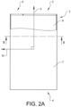
- Fig. 2A is a schematic view of the air intake device 2 as seen from above in a direction in parallel with the Z-axis in Fig. 1 .
- the air intake device 2 comprises an inlet 4 for air, a first outlet 5 arranged for providing air to an engine (not shown in Fig. 2A ) of the vehicle and a second outlet 6 arranged for discharging liquid separated from the air provided to the first outlet 5.
- an engine not shown in Fig. 2A
- a second outlet 6 arranged for discharging liquid separated from the air provided to the first outlet 5.
- air will pass through the second outlet as well as any particles such as snow, ice and dirt.
- the air inlet 4 is preferably arranged in the front of the vehicle for receiving air in a direction in parallel with the X-axis illustrated in Fig. 1 .
- the air intake device 2 comprises an intermediate portion 7 forming an air channel 8 extending from the air inlet 4 to the first outlet 5 and the second outlet 6.
- a longitudinal main extension direction 9 of the air channel 8 and a direction 10 perpendicular to the longitudinal main extension direction 9 of the air channel 8 are indicated in Fig. 2A . These directions 9, 10 define a horizontal plane.
- the air intake device 2 is suitably made by one or more pipe portions for providing a hollow structure and forming the air channel 8.
- Fig. 2B is a cross-section view taken along B-B in Fig. 2A .
- the first outlet 5 is arranged to the right and the second outlet 6 is arranged to the left.
- the first outlet 5 and the second outlet 6 can be separated by a wall.
- the air channel 8 is divided into the first outlet 5 and second outlet 6 by a substantially vertical wall 16 at an end of the intermediate portion 7.
- connection pipes can be arranged at the first outlet 5 and the second outlet 6 for further transportation of air downstream the first outlet 5 and water downstream the second outlet 6.
- a bottom surface 11 on the inside of the intermediate portion 7 is inclined relative to a horizontal plane 12 for directing liquid in the air channel 8 towards the second outlet 6 by gravity.
- the bottom surface 11 is inclined relative to the plane defined by the X-axis and the Y-axis in Fig. 1 , when the air intake device is properly installed in the vehicle standing on even ground.
- the bottom surface 11 has an inclination angle ⁇ relative to the horizontal plane 12 in the direction 10 perpendicular to the longitudinal main extension direction 9 of the air channel 8.
- ⁇ is a transverse inclination angle. Due to the transverse inclination angle, the bottom surface 11 has a downward slope in a direction from the first outlet 5 to the second outlet 6.
- Fig. 2B' is a cross-section view taken along B-B in Fig. 2A for a further example embodiment of the air intake device 2'.
- the bottom surface 11' has a first part 13 extending to the first outlet 5', which first bottom surface part 13 has a first inclination angle ⁇ 1 relative to the horizontal plane 12, and a second part 14 extending to the second outlet 6, which second bottom surface part 14 has a second inclination angle ⁇ 2 relative to the horizontal plane 12.
- Fig. 2B " is a cross-section view taken along B-B in Fig. 2A for a further example embodiment of the air intake device.
- the bottom surface 11" has a first part 13" extending to the first outlet 5", which first bottom surface part 13" has a first inclination angle ⁇ 1 relative to the horizontal plane 12, and a second part 14" extending to the second outlet 6", which second bottom surface part 14" has a second inclination angle ⁇ 2 relative to the horizontal plane 12.
- the first bottom surface part 13" extending to the first outlet 5" and the second bottom surface part 14" extending to the second outlet 6" are connected by a threshold step 15 such that the first bottom surface part 13" is arranged on a higher level than the second bottom surface part 14".
- the threshold step has an extension component in the vertical direction.
- the threshold step 15, which can be formed by a vertical or inclined wall, is suitably arranged such that the threshold step 15 divides the intermediate portion bottom surface 11" into the first bottom surface part 13" extending to the first outlet 5" and the second bottom surface part 14" extending to the second outlet 6".
- the threshold step 15 and the wall 16 separating the first inlet and the second inlet from each other can be arranged at the same position with respect to the direction 10 perpendicular to the longitudinal main extension direction 9 of the air channel 8.
- the width of the air channel part having the first bottom surface part 13" can correspond to the width of the first outlet 5" and the width of the air channel part having the second bottom surface part 14" can correspond to the width of the second outlet 6".
- Fig. 2C is a cut view taken along C-C in Fig. 2B .
- the bottom surface 11 has an inclination angle ⁇ relative to the horizontal plane 12 in the longitudinal main extension direction 9 of the air channel 8.
- ⁇ is a longitudinal inclination angle.
- the bottom surface 11 due to the longitudinal inclination angle the bottom surface 11 has an upward slope as seen in the direction from the inlet 4 to the first outlet 5.
- Fig. 2D and Fig. 2E are cut views taken along D-D and E-E, respectively, in Fig. 2B' .
- the bottom surface 11' has a first part 13 extending to the first outlet 5', which first bottom surface part 13 has a first inclination angle ⁇ 1, and a second part 14 extending to the second outlet 6', which second bottom surface part 14 has a second inclination angle ⁇ 2, where the first inclination angle ⁇ 1 and the second inclination angle ⁇ 2 are different from each other.
- first inclination angle ⁇ 1 and the second inclination angle ⁇ 2 are different from each other.
- the first bottom surface part 13 extending to the first outlet 5' has an upward slope as seen in the direction from the inlet 4 to the first outlet 5' and the second bottom surface part 14 extending to the second outlet 6' has a downward slope as seen in the direction from the inlet 4 to the second outlet 6'.
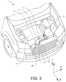
- Fig. 3 shows an example embodiment of the air intake device 20 when assembled in the vehicle 1.
- the air inlet 4 of the air intake device 20 is facing in a direction in parallel with the X-axis for receiving air from a position in the front of the vehicle 1.
- the air inlet could however be arranged in another direction, for example the air inlet could be facing in a direction in parallel with the Y-axis.
- some water, snow, ice and/or dirt may unintentionally pass the air inlet 4 and reach the intermediate portion 7.
- the first outlet 5 of the air intake device 20 is connected to a filter box 21. Inside the filter box 21 one or more air filters is arranged for cleaning the air before the air reaches the engine 3.
- the second outlet 6 is arranged for discharging liquid such as water, separated from the air provided to the first outlet 5. Also air will pass through the second outlet 6 as well as particles such as snow, ice and dirt.
- the intermediate portion 7 has a bend portion 22 making the air channel 8 extending from the inlet 4 to the first outlet 5 and the second outlet 6 curved.
- the intermediate portion 7 is suitably curved in the horizontal plane defined by the X-axis and the Y-axis.
- Fig. 4B is a cut view taken along B-B in Fig. 4A , where the bottom surface 11 of the bend portion 22 is shown.
- the first bottom surface part 13 extending to the first outlet 5 and the second bottom surface part 14 extending to the second outlet 6 are arranged side by side in the bend portion 22.
- the first bottom surface part 13 extending to the first outlet 5 is arranged along an inner curve of the bend portion 22 and the second bottom surface part 14 extending to the second outlet 6 is arranged along an outer curve of the bend portion 22.
- the first bottom surface part 13 can have a first inclination angle (indicated as ⁇ 1 in previous Figs.) relative to the horizontal plane 12 forming an upward slope as seen in the direction from the inlet 4 to the first outlet 5.
- the second bottom surface part 14 can have a second inclination angle (indicated as ⁇ 2 in previous Figs.) relative to the horizontal plane 12 forming a downward slope as seen in the direction from the inlet 4 to the second outlet 6.
- the longitudinal main extension direction 9 of the air channel 8 is of course not constant, but is rather represented by the tangent to the curve of the intermediate portion 7.
- first bottom surface part 13 can have a first inclination angle ⁇ 1 relative to the horizontal plane 12 in the direction 10 perpendicular to the longitudinal main extension direction 9 of the air channel 8
- second bottom surface part 14 can have a second inclination angle ⁇ 2 relative to the horizontal plane 12 in the direction 10 perpendicular to the longitudinal main extension direction of the air channel, as also described for previous example embodiments hereinabove.
- Fig. 4C is a cross-section view taken along C-C in Fig. 4B .
- the bend portion 22 has a downward slope in a direction from the first outlet 5 to the second outlet 6 along both the first bottom surface part 13 and the second bottom surface part 14.
- the inclination angles ( ⁇ , ⁇ 1, ⁇ 2, ⁇ , ⁇ 1, ⁇ 2) do not need to be constants, but can vary along the longitudinal main extension direction of the air channel of the intermediate portion.
- the transverse inclination angle ⁇ 1 can be increasing in the direction from the air inlet to the first outlet.
- the longitudinal inclination angle ⁇ 1 can also be increasing in the direction from the air inlet to the first outlet.
- the first outlet 5 of the air intake device 20' is connected to a filter box 21. Inside the filter box 21 one or more air filters is arranged for cleaning the air before the air reaches the engine 3.
- the second outlet 6 is arranged for discharging liquid such as water, separated from the air provided to the first outlet 5. Also air will pass through the second outlet 6 as well as particles such as snow, ice and dirt.
- the intermediate portion 7 has a bend portion 22' making the air channel 8 extending from the inlet 4 to the first outlet 5 and the second outlet 6 curved.
- the intermediate portion 7 is suitably curved in the horizontal plane defined by the X-axis and the Y-axis.
- Fig. 6B is a cut view taken along B-B in Fig. 6A , where the bottom surface 11 of the bend portion 22' is shown.
- the first bottom surface part 13 extending to the first outlet 5 and the second bottom surface part 14 extending to the second outlet 6 are arranged side by side in the bend portion 22'.
- the first bottom surface part 13 extending to the first outlet 5 is arranged along an inner curve of the bend portion 22' and the second bottom surface part 14 extending to the second outlet 6 is arranged along an outer curve of the bend portion 22'.
- a part 23 of the intermediate portion bottom surface 13 adjacent to the first outlet 5 and a bottom surface 24 defining the first outlet 5 are connected by a threshold step 25 such that the first outlet bottom surface 24 is arranged at a higher level than the adjacent intermediate portion bottom surface part 23.
- the longitudinal main extension direction 9 of the air channel 8 is of course not constant, but is rather represented by the tangent to the curve of the intermediate portion 7.
- first bottom surface part 13 can have a first inclination angle ⁇ 1 relative to the horizontal plane 12 in the direction 10 perpendicular to the longitudinal main extension direction 9 of the air channel 8 and the second bottom surface part 14 can have a second inclination angle ⁇ 2 relative to the horizontal plane 12 in the direction 10 perpendicular to the longitudinal main extension direction of the air channel, as also described for previous example embodiments hereinabove.
- Fig. 6C is a cross-section view taken along C-C in Fig. 6B .
- the bend portion 22' has a downward slope in a direction from the first outlet 5 to the second outlet 6 along both the first bottom surface part 13 and the second bottom surface part 14.
Landscapes
- Engineering & Computer Science (AREA)
- Chemical & Material Sciences (AREA)
- Combustion & Propulsion (AREA)
- Mechanical Engineering (AREA)
- General Engineering & Computer Science (AREA)
- Chemical Kinetics & Catalysis (AREA)
- Cooling, Air Intake And Gas Exhaust, And Fuel Tank Arrangements In Propulsion Units (AREA)
- Air-Conditioning For Vehicles (AREA)
- Jet Pumps And Other Pumps (AREA)
Description
- The invention relates to an air intake device for a vehicle, for providing air to an engine of the vehicle.
- A vehicle with an internal combustion engine (ICE) has an air intake for providing air to the engine. The air usually passes a filter box with an air filter where the air is cleaned from particles etc. before entering the engine. Upstream the filter box the air intake has a duct for leading air from the front part of the vehicle towards the engine.
- It is important that water does not reach the filter box via the air intake duct and further into the engine which otherwise could cause engine failure, for example when the vehicle is to be started. A vehicle has to undergo tests where the vehicle is exposed to water and the air intake should be designed to be able to manage such tests and prevent or at least counteract water from reaching the air filter.
- The document
US4699639 is directed to a unitary member formed to fit in the engine compartment of a vehicle. The unitary member includes an intermediate portion having a moisture elimination section. This document describes a device according to the preamble ofclaim 1. - The document
JP2014141908 - An objective of the invention is to provide an air intake device for a vehicle, for providing air to an engine of the vehicle, which device has an improved ability to prevent water from reaching the engine of the vehicle.
- The objective is achieved by an air intake device according to
claim 1. - The invention is based on the insight that by such an air intake device, water accidentally entering the inlet of the air intake device can be drained and led out from the system through the second outlet.
- Hereby, any water in the air channel can be directed towards the second outlet by centrifugal force. By the inclination angles β1 and β2, it is possible to counteract water to reach the first outlet and facilitate water to reach the second outlet.
- The expression "inclined relative to a horizontal plane" is used with respect to the orientation of a bottom surface when the air intake device is installed in the intended position in a vehicle, which vehicle stands on substantially level ground. In other words; the orientation of the bottom surface of the intermediate portion is arranged such when the air intake device is installed in the vehicle, the bottom surface is inclined relative to the horizontal plane when the vehicle is standing horizontally. This is also true for other inclination angles described herein unless other is explicitly stated.
- The term inlet is used for an opening where air is intended to flow into the air channel of the intermediate portion. The terms first outlet and second outlet are used for describing openings where the air and any water, respectively, are intended to leave the air channel of the intermediate portion. However, downstream the first outlet and/or the second outlet a further channel can be arranged for further transportation of the air and any water drained from the air, respectively. The first outlet and the second outlet can be arranged to face in a longitudinal main extension direction of the air channel and be arranged adjacent to each other. Hereby, an efficient drainage of water can be achieved by a compact and non-complicated design of the air intake device.
- According to one embodiment of the device, the bottom surface has an inclination angle α relative to the horizontal plane in a direction perpendicular to a longitudinal main extension direction of the air channel, and preferably the bottom surface has a downward slope in a direction from the first outlet to the second outlet. Hereby, an efficient drainage of water can be achieved since any water present in the air channel is directed towards the second inlet by gravity.
- The inclination angle α can be in the
interval 0<α<30°, suitably 2<α<20°, preferably 3<α<15°, and often 5<α<10°. - The bottom surface has a first part extending to the first outlet, which first bottom surface part has a first inclination angle α1, and a second part extending to the second outlet, which second bottom surface part has a second inclination angle α2. The first bottom surface part extending to the first outlet and the second bottom surface part extending to the second outlet can be connected by a threshold step such that the first bottom surface part is arranged on a higher level than the second bottom surface part. The first bottom surface part extending to the first outlet and the second bottom surface part extending to the second outlet can be arranged side by side in the intermediate portion.
- The first inclination angle α1 can be in the
interval 0<α1<30°, suitably 2<α1<20°, preferably 3<α1<15°, and often 5<α1<10°. - The second inclination angle α2 can be in the
interval 0<α2<30°, suitably 2<α2<20°, preferably 3<α2<15°, and often 5<α2<10°. - The first inclination angle α1 and the second inclination angle α2 can be different from each other.
- The first bottom surface part extending to the first outlet can have an upward slope as seen in the direction from the inlet to the first outlet, and the second bottom surface part extending to the second outlet can have a downward slope as seen in the direction from the inlet to the second outlet.
- The first inclination angle β1 can be in the
interval 0<β1<30°, suitably 2<β1<20°, preferably 3<β1<15°, and often 5<β1<10°. - The second inclination angle β2 can be in the
interval 0<β2<30°, suitably 2<β2<20°, preferably 3<β2<15°, and often 5<β2<10°. - According to a further embodiment, a part of the intermediate portion bottom surface adjacent to the first outlet and a bottom surface defining the first outlet are connected by a threshold step such that the first outlet bottom surface is arranged at a higher level than the adjacent intermediate portion bottom surface part. Hereby, it is possible to further counteract water from reaching the first outlet.
- Another aspect of the invention relates to vehicle comprising an air intake device. The advantages of the vehicle are substantially the same as described for the air intake device described hereinabove.
- Further advantages and advantageous features of the invention are disclosed in the following description and in the claims.
- With reference to the appended drawings, below follows a more detailed description of embodiments of the invention cited as examples.
- In the drawings:
-
Fig. 1 shows a vehicle with an air intake device for providing air to an engine, -
Fig. 2A is a schematic view of an air intake device, -
Fig. 2B is cross-section view taken along B-B inFig. 2A , -
Fig. 2B' shows a variant of the air intake device inFig. 2A , -
Fig. 2B " shows a further variant of the air intake device inFig. 2A , -
Fig. 2C is a cut view taken along C-C inFig. 2B , -
Fig. 2D is a cut view taken along D-D inFig. 2B' , -
Fig. 2E is a cut view taken along E-E inFig. 2B' , -
Fig. 3 is a perspective view of a vehicle showing the engine compartment with an air intake device, -
Fig. 4A is a perspective view of the air intake device inFig. 3 , -
Fig. 4B is a cut view taken along B-B inFig. 4A , -
FIG. 4C is a cross-section view taken along C-C inFig. 4B , -
Fig. 5 is a perspective view of a vehicle showing the engine compartment with a further variant of an air intake device, -
Fig. 6A is a perspective view of the air intake device inFig. 5 , -
Fig. 6B is a cut view taken along B-B inFig. 6A , and -
Fig. 6C is a cross-section view taken along C-C inFig. 6B . -
Fig. 1 shows avehicle 1 with anair intake device 2. Theair intake device 2 is suitably arranged in the front of thevehicle 1 for providing air to anengine 3 of the vehicle. InFig. 1 , a cartesian coordinate system having an X-axis, a Y-axis and a Z-axis is also indicated. The X-axis is arranged in parallel with a longitudinal extension direction of the vehicle (i.e. the driving direction), the Z-axis is arranged in the vertical direction and a horizontal plane is defined by the X-axis and the Y-axis. -
Fig. 2A is a schematic view of theair intake device 2 as seen from above in a direction in parallel with the Z-axis inFig. 1 . As schematically illustrated inFig. 2A , theair intake device 2 comprises aninlet 4 for air, afirst outlet 5 arranged for providing air to an engine (not shown inFig. 2A ) of the vehicle and asecond outlet 6 arranged for discharging liquid separated from the air provided to thefirst outlet 5. In addition to liquid also air will pass through the second outlet as well as any particles such as snow, ice and dirt. - The
air inlet 4 is preferably arranged in the front of the vehicle for receiving air in a direction in parallel with the X-axis illustrated inFig. 1 . Further, theair intake device 2 comprises anintermediate portion 7 forming anair channel 8 extending from theair inlet 4 to thefirst outlet 5 and thesecond outlet 6. A longitudinalmain extension direction 9 of theair channel 8 and adirection 10 perpendicular to the longitudinalmain extension direction 9 of theair channel 8 are indicated inFig. 2A . Thesedirections air intake device 2 is suitably made by one or more pipe portions for providing a hollow structure and forming theair channel 8. -
Fig. 2B is a cross-section view taken along B-B inFig. 2A . Thefirst outlet 5 is arranged to the right and thesecond outlet 6 is arranged to the left. Thefirst outlet 5 and thesecond outlet 6 can be separated by a wall. In the example embodiment illustrated inFig. 2B , theair channel 8 is divided into thefirst outlet 5 andsecond outlet 6 by a substantiallyvertical wall 16 at an end of theintermediate portion 7. As previously mentioned hereinabove, connection pipes can be arranged at thefirst outlet 5 and thesecond outlet 6 for further transportation of air downstream thefirst outlet 5 and water downstream thesecond outlet 6. - A
bottom surface 11 on the inside of theintermediate portion 7 is inclined relative to ahorizontal plane 12 for directing liquid in theair channel 8 towards thesecond outlet 6 by gravity. This means that thebottom surface 11 is inclined relative to the plane defined by the X-axis and the Y-axis inFig. 1 , when the air intake device is properly installed in the vehicle standing on even ground. Thebottom surface 11 has an inclination angle α relative to thehorizontal plane 12 in thedirection 10 perpendicular to the longitudinalmain extension direction 9 of theair channel 8. In other words; α is a transverse inclination angle. Due to the transverse inclination angle, thebottom surface 11 has a downward slope in a direction from thefirst outlet 5 to thesecond outlet 6. -
Fig. 2B' is a cross-section view taken along B-B inFig. 2A for a further example embodiment of the air intake device 2'. The bottom surface 11' has afirst part 13 extending to the first outlet 5', which firstbottom surface part 13 has a first inclination angle α1 relative to thehorizontal plane 12, and asecond part 14 extending to thesecond outlet 6, which secondbottom surface part 14 has a second inclination angle α2 relative to thehorizontal plane 12. -
Fig. 2B " is a cross-section view taken along B-B inFig. 2A for a further example embodiment of the air intake device. In the same way as described with reference toFig. 2B' , thebottom surface 11" has afirst part 13" extending to thefirst outlet 5", which firstbottom surface part 13" has a first inclination angle α1 relative to thehorizontal plane 12, and asecond part 14" extending to thesecond outlet 6", which secondbottom surface part 14" has a second inclination angle α2 relative to thehorizontal plane 12. - In the example embodiment illustrated in
Fig. 2B ", the firstbottom surface part 13" extending to thefirst outlet 5" and the secondbottom surface part 14" extending to thesecond outlet 6" are connected by athreshold step 15 such that the firstbottom surface part 13" is arranged on a higher level than the secondbottom surface part 14". In other words; the threshold step has an extension component in the vertical direction. Thethreshold step 15, which can be formed by a vertical or inclined wall, is suitably arranged such that thethreshold step 15 divides the intermediateportion bottom surface 11" into the firstbottom surface part 13" extending to thefirst outlet 5" and the secondbottom surface part 14" extending to thesecond outlet 6". In other words; thethreshold step 15 and thewall 16 separating the first inlet and the second inlet from each other, can be arranged at the same position with respect to thedirection 10 perpendicular to the longitudinalmain extension direction 9 of theair channel 8. Thus, the width of the air channel part having the firstbottom surface part 13" can correspond to the width of thefirst outlet 5" and the width of the air channel part having the secondbottom surface part 14" can correspond to the width of thesecond outlet 6". -
Fig. 2C is a cut view taken along C-C inFig. 2B . As illustrated inFig. 2C , thebottom surface 11 has an inclination angle β relative to thehorizontal plane 12 in the longitudinalmain extension direction 9 of theair channel 8. In other words; β is a longitudinal inclination angle. In the example embodiment illustrated inFig. 2C , due to the longitudinal inclination angle thebottom surface 11 has an upward slope as seen in the direction from theinlet 4 to thefirst outlet 5. -
Fig. 2D and Fig. 2E are cut views taken along D-D and E-E, respectively, inFig. 2B' . As illustrated inFigs. 2D and 2E , the bottom surface 11' has afirst part 13 extending to the first outlet 5', which firstbottom surface part 13 has a first inclination angle β1, and asecond part 14 extending to the second outlet 6', which secondbottom surface part 14 has a second inclination angle β2, where the first inclination angle β1 and the second inclination angle β2 are different from each other. In the example embodiment illustrated inFigs. 2D and 2E , the firstbottom surface part 13 extending to the first outlet 5' has an upward slope as seen in the direction from theinlet 4 to the first outlet 5' and the secondbottom surface part 14 extending to the second outlet 6' has a downward slope as seen in the direction from theinlet 4 to the second outlet 6'. -
Fig. 3 shows an example embodiment of theair intake device 20 when assembled in thevehicle 1. Theair inlet 4 of theair intake device 20 is facing in a direction in parallel with the X-axis for receiving air from a position in the front of thevehicle 1. In another embodiment the air inlet could however be arranged in another direction, for example the air inlet could be facing in a direction in parallel with the Y-axis. In addition to air, some water, snow, ice and/or dirt may unintentionally pass theair inlet 4 and reach theintermediate portion 7. - The
first outlet 5 of theair intake device 20 is connected to afilter box 21. Inside thefilter box 21 one or more air filters is arranged for cleaning the air before the air reaches theengine 3. Thesecond outlet 6 is arranged for discharging liquid such as water, separated from the air provided to thefirst outlet 5. Also air will pass through thesecond outlet 6 as well as particles such as snow, ice and dirt. - The
intermediate portion 7 has abend portion 22 making theair channel 8 extending from theinlet 4 to thefirst outlet 5 and thesecond outlet 6 curved. Theintermediate portion 7 is suitably curved in the horizontal plane defined by the X-axis and the Y-axis. -
Fig. 4A shows an enlarged view of theair intake device 20 and thefilter box 21 illustrated inFig. 3 . In this example embodiment, thebend portion 22 of theintermediate portion 7 is provided with the bottom surface being inclined relative to the horizontal plane. This is further illustrated inFig. 4B . Thebend portion 22 of theintermediate portion 7 can extend approximately 180° and theintermediate portion 7 can be S-shaped. -
Fig. 4B is a cut view taken along B-B inFig. 4A , where thebottom surface 11 of thebend portion 22 is shown. The firstbottom surface part 13 extending to thefirst outlet 5 and the secondbottom surface part 14 extending to thesecond outlet 6 are arranged side by side in thebend portion 22. The firstbottom surface part 13 extending to thefirst outlet 5 is arranged along an inner curve of thebend portion 22 and the secondbottom surface part 14 extending to thesecond outlet 6 is arranged along an outer curve of thebend portion 22. - A
part 23 of the intermediateportion bottom surface 13 adjacent to thefirst outlet 5 and abottom surface 24 defining thefirst outlet 5 are connected by athreshold step 25 such that the firstoutlet bottom surface 24 is arranged at a higher level than the adjacent intermediate portionbottom surface part 23. - As has been previously described hereinabove with reference to previous figures, such as
Figs. 2B', 2B ",2D and 2E , also in this example embodiment illustrated inFigs. 4A and4B , the firstbottom surface part 13 can have a first inclination angle (indicated as β1 in previous Figs.) relative to thehorizontal plane 12 forming an upward slope as seen in the direction from theinlet 4 to thefirst outlet 5. Further, the secondbottom surface part 14 can have a second inclination angle (indicated as β2 in previous Figs.) relative to thehorizontal plane 12 forming a downward slope as seen in the direction from theinlet 4 to thesecond outlet 6. Optionally, only the firstbottom surface part 13 has an inclination angle β1 relative to the horizontal plane in the longitudinalmain extension direction 9 of theair channel 8, i.e. β2 = 0. - Along the
bend portion 22, the longitudinalmain extension direction 9 of theair channel 8 is of course not constant, but is rather represented by the tangent to the curve of theintermediate portion 7. - Further, the first
bottom surface part 13 can have a first inclination angle α1 relative to thehorizontal plane 12 in thedirection 10 perpendicular to the longitudinalmain extension direction 9 of theair channel 8, and the secondbottom surface part 14 can have a second inclination angle α2 relative to thehorizontal plane 12 in thedirection 10 perpendicular to the longitudinal main extension direction of the air channel, as also described for previous example embodiments hereinabove. -
Fig. 4C is a cross-section view taken along C-C inFig. 4B . As illustrated inFig. 4C , thebend portion 22 has a downward slope in a direction from thefirst outlet 5 to thesecond outlet 6 along both the firstbottom surface part 13 and the secondbottom surface part 14. Optionally, only the firstbottom surface part 13 has an inclination angle α1 relative to thehorizontal plane 12 in thedirection 10 perpendicular to the longitudinalmain extension direction 9 of theair channel 8, i.e. α2 = 0. - With respect to all example embodiments described herein, it should be stressed that the inclination angles (α, α1, α2, β, β1, β2) do not need to be constants, but can vary along the longitudinal main extension direction of the air channel of the intermediate portion. For example, in the example embodiment described above, optionally the transverse inclination angle α1 can be increasing in the direction from the air inlet to the first outlet. Optionally, the longitudinal inclination angle β1 can also be increasing in the direction from the air inlet to the first outlet.
-
Fig. 5 shows a further example embodiment of the air intake device when assembled in the vehicle. Theair inlet 4 of the air intake device 20' is facing in a direction in parallel with the X-axis for receiving air from a position in the front of thevehicle 1. In addition to air, some water, snow, ice and/or dirt may unintentionally pass theair inlet 4 and reach theintermediate portion 7. - The
first outlet 5 of the air intake device 20' is connected to afilter box 21. Inside thefilter box 21 one or more air filters is arranged for cleaning the air before the air reaches theengine 3. Thesecond outlet 6 is arranged for discharging liquid such as water, separated from the air provided to thefirst outlet 5. Also air will pass through thesecond outlet 6 as well as particles such as snow, ice and dirt. - The
intermediate portion 7 has a bend portion 22' making theair channel 8 extending from theinlet 4 to thefirst outlet 5 and thesecond outlet 6 curved. Theintermediate portion 7 is suitably curved in the horizontal plane defined by the X-axis and the Y-axis. -
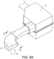
Fig. 6A shows an enlarged view of the air intake device 20' and thefilter box 21 illustrated inFig. 5 . In this example embodiment, the bend portion 22' of theintermediate portion 7 is provided with the bottom surface which is inclined relative to the horizontal plane. This is further illustrated inFig. 6B . The bend portion 22' of theintermediate portion 7 can extend approximately 90°. -
Fig. 6B is a cut view taken along B-B inFig. 6A , where thebottom surface 11 of the bend portion 22' is shown. The firstbottom surface part 13 extending to thefirst outlet 5 and the secondbottom surface part 14 extending to thesecond outlet 6 are arranged side by side in the bend portion 22'. The firstbottom surface part 13 extending to thefirst outlet 5 is arranged along an inner curve of the bend portion 22' and the secondbottom surface part 14 extending to thesecond outlet 6 is arranged along an outer curve of the bend portion 22'. - A
part 23 of the intermediateportion bottom surface 13 adjacent to thefirst outlet 5 and abottom surface 24 defining thefirst outlet 5 are connected by athreshold step 25 such that the firstoutlet bottom surface 24 is arranged at a higher level than the adjacent intermediate portionbottom surface part 23. - As has been previously described hereinabove, also in this example embodiment illustrated in
Figs. 6A and6B , the firstbottom surface part 13 can have a first inclination angle (indicated as β1 in previous Figs.) relative to thehorizontal plane 12 forming an upward slope as seen in the direction from theinlet 4 to thefirst outlet 5. Further, the secondbottom surface part 14 can have a second inclination angle (indicated as β2 in previous Figs.) relative to thehorizontal plane 12 forming a downward slope as seen in the direction from theinlet 4 to thesecond outlet 6. Optionally, only the firstbottom surface part 13 has an inclination angle β1 relative to the horizontal plane in the longitudinalmain extension direction 9 of theair channel 8, i.e. β2 = 0. - Along the bend portion 22', the longitudinal
main extension direction 9 of theair channel 8 is of course not constant, but is rather represented by the tangent to the curve of theintermediate portion 7. - Further, the first
bottom surface part 13 can have a first inclination angle α1 relative to thehorizontal plane 12 in thedirection 10 perpendicular to the longitudinalmain extension direction 9 of theair channel 8 and the secondbottom surface part 14 can have a second inclination angle α2 relative to thehorizontal plane 12 in thedirection 10 perpendicular to the longitudinal main extension direction of the air channel, as also described for previous example embodiments hereinabove. -
Fig. 6C is a cross-section view taken along C-C inFig. 6B . As illustrated inFig. 6C , the bend portion 22' has a downward slope in a direction from thefirst outlet 5 to thesecond outlet 6 along both the firstbottom surface part 13 and the secondbottom surface part 14. Optionally, only the firstbottom surface part 13 has an inclination angle α1 relative to thehorizontal plane 12 in thedirection 10 perpendicular to the longitudinalmain extension direction 9 of theair channel 8, i.e. α2 = 0. - It is to be understood that the present invention is not limited to the embodiments described above and illustrated in the drawings; rather, the skilled person will recognize that many changes and modifications may be made within the scope of the appended claims.
Claims (9)
- An air intake device (2) for a vehicle (1), the device comprising an inlet (4) for air, a first outlet (5,5',5") arranged for providing air to an engine (3) of the vehicle and a second outlet (6,6',6") arranged for discharging liquid separated from the air provided to the first outlet (5,5',5"), and an intermediate portion (7) forming an air channel (8) extending from the inlet (4) to the first outlet (5,5',5") and the second outlet (6,6',6"), a bottom surface (11,11',11") on the inside of the intermediate portion (7) being inclined relative to a horizontal plane (12) for directing liquid in the air channel (8) towards the second outlet (6,6',6"), the bottom surface (11,11',11") having a longitudinal inclination angle (β) relative to the horizontal plane (12) in a longitudinal main extension direction (9) of the air channel (8), the bottom surface (11,11',11") having a first bottom surface part (13,13") extending to the first outlet (5,5',5"), which first bottom surface part (13,13") has a first longitudinal inclination angle (β1), and a second bottom surface part (14,14") extending to the second outlet (6,6',6"), which second bottom surface part (14,14") has a second longitudinal inclination angle (β2), the first longitudinal inclination angle (β1) and the second longitudinal inclination angle (β2) being different from each other, the first bottom surface part (13,13") extending to the first outlet (5,5',5") and the second bottom surface part (14,14") extending to the second outlet (6,6',6") are arranged side by side in the intermediate portion (7),wherein the intermediate portion (7) has a bend portion (22) making the air channel (8) curved in the horizontal plane, the first bottom surface part (13,13") extending to the first outlet (5,5',5") and the second bottom surface part (14,14") extending to the second outlet (6,6',6") being arranged side by side in the bend portion (22),characterized in that the first bottom surface part (13,13") extending to the first outlet (5,5',5") being arranged along an inner curve of the bend portion (22) and the second bottom surface part (14,14") extending to the second outlet (6,6',6") being arranged along an outer curve of the bend portion (22).
- A device according to claim 1, characterized in that the bottom surface (11,11',11") has a transverse inclination angle (α) relative to the horizontal plane (12) in a direction perpendicular to the longitudinal main extension direction (9) of the air channel (8).
- A device according to claim 2, characterized in that the bottom surface (11,11',11") has a downward slope in a direction from the first outlet (5,5',5") to the second outlet (6,6',6").
- A device according to claim 2 or 3, characterized in that the bottom surface (11,11',11") has a first bottom surface part (13,13") extending to the first outlet (5,5',5"), which first bottom surface part (13,13") has a first transverse inclination angle (α1), and a second bottom surface part (14,14") extending to the second outlet (6,6',6"), which second bottom surface part (14,14") has a second transverse inclination angle (α2).
- A device according to claim 4, characterized in that the first transverse inclination angle (α1) and the second transverse inclination angle (α2) are different from each other.
- A device according to claim 4 or 5, characterized in that the first bottom surface part (13,13") extending to the first outlet (5,5',5") and the second bottom surface part (14,14") extending to the second outlet (6,6',6") are connected by a threshold step (15) such that the first bottom surface part (13,13") is arranged on a higher level than the second bottom surface part (14,14").
- A device according to any preceding claim, characterized in that the first bottom surface part (13,13") extending to the first outlet (5,5',5") has an upward slope as seen in the direction from the inlet (4) to the first outlet (5,5',5").
- A device according to any preceding claim, characterized in that the second bottom surface part (14,14") extending to the second outlet (6,6',6") has a downward slope as seen in the direction from the inlet (4) to the second outlet (6,6',6").
- A vehicle (1) comprising an air intake device (2) according to any of claims 1-8.
Priority Applications (4)
| Application Number | Priority Date | Filing Date | Title |
|---|---|---|---|
| EP19160110.3A EP3702606B1 (en) | 2019-02-28 | 2019-02-28 | An air intake device for a vehicle |
| PCT/CN2020/075546 WO2020173323A1 (en) | 2019-02-28 | 2020-02-17 | An air intake device for a vehicle |
| CN202080015604.7A CN113453934B (en) | 2019-02-28 | 2020-02-17 | Air intake device for vehicle |
| US17/405,941 US11719201B2 (en) | 2019-02-28 | 2021-08-18 | Air intake device for a vehicle |
Applications Claiming Priority (1)
| Application Number | Priority Date | Filing Date | Title |
|---|---|---|---|
| EP19160110.3A EP3702606B1 (en) | 2019-02-28 | 2019-02-28 | An air intake device for a vehicle |
Publications (2)
| Publication Number | Publication Date |
|---|---|
| EP3702606A1 EP3702606A1 (en) | 2020-09-02 |
| EP3702606B1 true EP3702606B1 (en) | 2024-10-23 |
Family
ID=65686692
Family Applications (1)
| Application Number | Title | Priority Date | Filing Date |
|---|---|---|---|
| EP19160110.3A Active EP3702606B1 (en) | 2019-02-28 | 2019-02-28 | An air intake device for a vehicle |
Country Status (4)
| Country | Link |
|---|---|
| US (1) | US11719201B2 (en) |
| EP (1) | EP3702606B1 (en) |
| CN (1) | CN113453934B (en) |
| WO (1) | WO2020173323A1 (en) |
Families Citing this family (3)
| Publication number | Priority date | Publication date | Assignee | Title |
|---|---|---|---|---|
| US12180916B2 (en) | 2020-02-09 | 2024-12-31 | Velossa Tech Engineering Inc. | Interchangeable intake manifold assemblies |
| USD993282S1 (en) * | 2021-06-11 | 2023-07-25 | Velossa Tech Engineering Inc. | Ram-air intake |
| USD992601S1 (en) * | 2021-06-11 | 2023-07-18 | Velossa Tech Engineering Inc. | Ram-air intake |
Family Cites Families (28)
| Publication number | Priority date | Publication date | Assignee | Title |
|---|---|---|---|---|
| US2267706A (en) * | 1939-10-18 | 1941-12-30 | Standard Supercharger Corp | Combined supercharger and air cleaner |
| GB849909A (en) * | 1955-09-20 | 1960-09-28 | Bayerische Motoren Werke Ag | Improved air intake in internal combustion engine driven motor vehicles |
| US4878555A (en) * | 1984-12-13 | 1989-11-07 | Honad Giken Kogyo Kabushiki Kaisha | Air intake device for a vehicle engine |
| US4793293A (en) * | 1986-03-07 | 1988-12-27 | Honda Giken Kogyo Kabushiki Kaisha | Cooling air intake structure for small-sized vehicles |
| US4699639A (en) * | 1986-07-16 | 1987-10-13 | Donaldson Company, Inc. | Air-intake, moisture-eliminator duct apparatus |
| JPS63100256A (en) * | 1986-10-15 | 1988-05-02 | Kawasaki Heavy Ind Ltd | Dust exhaust device for air cleaner |
| JP2526659Y2 (en) * | 1991-06-24 | 1997-02-19 | マツダ株式会社 | Vehicle intake duct intake structure |
| JP3207253B2 (en) * | 1992-06-30 | 2001-09-10 | 三信工業株式会社 | Cowling structure for ship propulsion |
| US5564513A (en) * | 1994-07-12 | 1996-10-15 | Automotive Performance International, Inc. | Air filter housing for automobile internal combustion engine |
| JP2004218482A (en) * | 2003-01-10 | 2004-08-05 | Toyota Motor Corp | Air cleaner |
| JP4184923B2 (en) * | 2003-11-06 | 2008-11-19 | 本田技研工業株式会社 | Air cleaner structure |
| US7069893B2 (en) * | 2004-06-14 | 2006-07-04 | Ford Motor Company | Air intake system |
| JP4712096B2 (en) * | 2009-01-07 | 2011-06-29 | 本田技研工業株式会社 | Air intake structure for automobiles |
| FR2982800B1 (en) * | 2011-11-21 | 2013-11-22 | Peugeot Citroen Automobiles Sa | AIR INTAKE SYSTEM FOR MOTOR VEHICLE, INCLUDING AN IMPROVED DRAINAGE SYSTEM |
| JP5474151B2 (en) * | 2012-09-20 | 2014-04-16 | 株式会社イノアックコーポレーション | Intake duct for vehicle |
| DE102012023856B4 (en) * | 2012-12-06 | 2015-06-25 | Mann + Hummel Gmbh | Intake module of an air intake tract of an internal combustion engine |
| JP2014141908A (en) * | 2013-01-23 | 2014-08-07 | Suzuki Motor Corp | Intake system of engine |
| JPWO2015033778A1 (en) * | 2013-09-05 | 2017-03-02 | 本田技研工業株式会社 | Vehicle front structure |
| CN104727995B (en) * | 2013-12-19 | 2017-04-19 | 广州汽车集团股份有限公司 | Air feeding structure and system for automobile and corresponding automobile |
| US9222448B2 (en) * | 2014-02-14 | 2015-12-29 | Cnh Industrial America Llc | Air intake system for a work vehicle with improved fan aspiration |
| US9062639B1 (en) * | 2014-04-16 | 2015-06-23 | GM Global Technology Operations LLC | Dual inlet air induction system with panel filter for vehicle engine |
| JP6417860B2 (en) * | 2014-11-04 | 2018-11-07 | スズキ株式会社 | Intake device for internal combustion engine |
| KR101619901B1 (en) * | 2015-03-10 | 2016-05-13 | 주식회사 리한 | Air ducts having water inflow prevent unit |
| JP2016175520A (en) * | 2015-03-19 | 2016-10-06 | いすゞ自動車株式会社 | Air intake duct |
| CN204691947U (en) * | 2015-05-13 | 2015-10-07 | 重庆长安汽车股份有限公司 | A kind of air filter of automobile waterproof suction port assembly |
| CN204956087U (en) * | 2015-09-07 | 2016-01-13 | 安徽安凯汽车股份有限公司 | Passenger train box that admits air |
| JP6626776B2 (en) * | 2016-04-19 | 2019-12-25 | 日野自動車株式会社 | Intake duct |
| CN107542606B (en) * | 2016-06-29 | 2020-01-14 | 长城汽车股份有限公司 | Air inlet structure, air filter and vehicle |
-
2019
- 2019-02-28 EP EP19160110.3A patent/EP3702606B1/en active Active
-
2020
- 2020-02-17 CN CN202080015604.7A patent/CN113453934B/en active Active
- 2020-02-17 WO PCT/CN2020/075546 patent/WO2020173323A1/en not_active Ceased
-
2021
- 2021-08-18 US US17/405,941 patent/US11719201B2/en active Active
Also Published As
| Publication number | Publication date |
|---|---|
| EP3702606A1 (en) | 2020-09-02 |
| CN113453934A (en) | 2021-09-28 |
| US20210381476A1 (en) | 2021-12-09 |
| WO2020173323A1 (en) | 2020-09-03 |
| US11719201B2 (en) | 2023-08-08 |
| CN113453934B (en) | 2024-05-31 |
Similar Documents
| Publication | Publication Date | Title |
|---|---|---|
| US11719201B2 (en) | Air intake device for a vehicle | |
| US7237635B2 (en) | Automobile over-bulkhead air intake system | |
| US7234555B2 (en) | Secondary path automobile air intake system | |
| US7959714B2 (en) | Authorized filter servicing and replacement | |
| US7393372B2 (en) | Air cleaner for an air induction assembly having primary and secondary inlets | |
| US6540802B2 (en) | Air intake system including a water separator with an inner pipe projecting into an outer pipe | |
| US10213718B2 (en) | Air intake water separator | |
| EP3051096B1 (en) | Intake gas cooling device for supercharged internal combustion engine | |
| US20110017535A1 (en) | Automobile over-bulkhead air intake system | |
| US6312488B1 (en) | Two-piece water separating apparatus and method of making same | |
| US7861814B2 (en) | Air intake system with flow-diverting plenum box | |
| CN111051657A (en) | Cylinder Head Oil Separator (Controlled Flow Oil Separator) for Internal Combustion Engines | |
| EP0937912A2 (en) | Air breather structure in transmission | |
| WO2013176841A1 (en) | Head cover baffle system for improving oil mist separation | |
| RU2443880C2 (en) | Gas turbine engine compressor air intake | |
| US7938213B2 (en) | Vehicle drain hole structure | |
| CN220319692U (en) | Cylinder head cover and motorcycle | |
| US6347989B1 (en) | Air intake manifold for a vehicle ventilation system | |
| JP4088505B2 (en) | Structure for preventing water entry in intake negative pressure extraction part of intake system of internal combustion engine | |
| JP3614653B2 (en) | Air cleaner drain structure | |
| JP2014141908A (en) | Intake system of engine | |
| JPH11294271A (en) | Air cleaner | |
| US20200340434A1 (en) | Vehicle air cleaner | |
| CN116753084B (en) | Cylinder head cover and motorcycle | |
| GB2643029A (en) | A breather expulsion catch tank |
Legal Events
| Date | Code | Title | Description |
|---|---|---|---|
| PUAI | Public reference made under article 153(3) epc to a published international application that has entered the european phase |
Free format text: ORIGINAL CODE: 0009012 |
|
| STAA | Information on the status of an ep patent application or granted ep patent |
Free format text: STATUS: REQUEST FOR EXAMINATION WAS MADE |
|
| 17P | Request for examination filed |
Effective date: 20190228 |
|
| AK | Designated contracting states |
Kind code of ref document: A1 Designated state(s): AL AT BE BG CH CY CZ DE DK EE ES FI FR GB GR HR HU IE IS IT LI LT LU LV MC MK MT NL NO PL PT RO RS SE SI SK SM TR |
|
| AX | Request for extension of the european patent |
Extension state: BA ME |
|
| STAA | Information on the status of an ep patent application or granted ep patent |
Free format text: STATUS: EXAMINATION IS IN PROGRESS |
|
| 17Q | First examination report despatched |
Effective date: 20220510 |
|
| GRAP | Despatch of communication of intention to grant a patent |
Free format text: ORIGINAL CODE: EPIDOSNIGR1 |
|
| STAA | Information on the status of an ep patent application or granted ep patent |
Free format text: STATUS: GRANT OF PATENT IS INTENDED |
|
| RAP3 | Party data changed (applicant data changed or rights of an application transferred) |
Owner name: NINGBO GEELY AUTOMOBILE RESEARCH & DEVELOPMENT CO., LTD. |
|
| INTG | Intention to grant announced |
Effective date: 20240515 |
|
| GRAS | Grant fee paid |
Free format text: ORIGINAL CODE: EPIDOSNIGR3 |
|
| GRAA | (expected) grant |
Free format text: ORIGINAL CODE: 0009210 |
|
| STAA | Information on the status of an ep patent application or granted ep patent |
Free format text: STATUS: THE PATENT HAS BEEN GRANTED |
|
| AK | Designated contracting states |
Kind code of ref document: B1 Designated state(s): AL AT BE BG CH CY CZ DE DK EE ES FI FR GB GR HR HU IE IS IT LI LT LU LV MC MK MT NL NO PL PT RO RS SE SI SK SM TR |
|
| REG | Reference to a national code |
Ref country code: GB Ref legal event code: FG4D |
|
| REG | Reference to a national code |
Ref country code: CH Ref legal event code: EP |
|
| REG | Reference to a national code |
Ref country code: DE Ref legal event code: R096 Ref document number: 602019060701 Country of ref document: DE |
|
| REG | Reference to a national code |
Ref country code: IE Ref legal event code: FG4D |
|
| REG | Reference to a national code |
Ref country code: LT Ref legal event code: MG9D |
|
| REG | Reference to a national code |
Ref country code: NL Ref legal event code: MP Effective date: 20241023 |
|
| REG | Reference to a national code |
Ref country code: AT Ref legal event code: MK05 Ref document number: 1735015 Country of ref document: AT Kind code of ref document: T Effective date: 20241023 |
|
| PG25 | Lapsed in a contracting state [announced via postgrant information from national office to epo] |
Ref country code: NL Free format text: LAPSE BECAUSE OF FAILURE TO SUBMIT A TRANSLATION OF THE DESCRIPTION OR TO PAY THE FEE WITHIN THE PRESCRIBED TIME-LIMIT Effective date: 20241023 |
|
| PG25 | Lapsed in a contracting state [announced via postgrant information from national office to epo] |
Ref country code: NL Free format text: LAPSE BECAUSE OF FAILURE TO SUBMIT A TRANSLATION OF THE DESCRIPTION OR TO PAY THE FEE WITHIN THE PRESCRIBED TIME-LIMIT Effective date: 20241023 |
|
| PG25 | Lapsed in a contracting state [announced via postgrant information from national office to epo] |
Ref country code: IS Free format text: LAPSE BECAUSE OF FAILURE TO SUBMIT A TRANSLATION OF THE DESCRIPTION OR TO PAY THE FEE WITHIN THE PRESCRIBED TIME-LIMIT Effective date: 20250223 Ref country code: HR Free format text: LAPSE BECAUSE OF FAILURE TO SUBMIT A TRANSLATION OF THE DESCRIPTION OR TO PAY THE FEE WITHIN THE PRESCRIBED TIME-LIMIT Effective date: 20241023 Ref country code: PT Free format text: LAPSE BECAUSE OF FAILURE TO SUBMIT A TRANSLATION OF THE DESCRIPTION OR TO PAY THE FEE WITHIN THE PRESCRIBED TIME-LIMIT Effective date: 20250224 |
|
| PG25 | Lapsed in a contracting state [announced via postgrant information from national office to epo] |
Ref country code: FI Free format text: LAPSE BECAUSE OF FAILURE TO SUBMIT A TRANSLATION OF THE DESCRIPTION OR TO PAY THE FEE WITHIN THE PRESCRIBED TIME-LIMIT Effective date: 20241023 |
|
| PG25 | Lapsed in a contracting state [announced via postgrant information from national office to epo] |
Ref country code: BG Free format text: LAPSE BECAUSE OF FAILURE TO SUBMIT A TRANSLATION OF THE DESCRIPTION OR TO PAY THE FEE WITHIN THE PRESCRIBED TIME-LIMIT Effective date: 20241023 |
|
| PG25 | Lapsed in a contracting state [announced via postgrant information from national office to epo] |
Ref country code: ES Free format text: LAPSE BECAUSE OF FAILURE TO SUBMIT A TRANSLATION OF THE DESCRIPTION OR TO PAY THE FEE WITHIN THE PRESCRIBED TIME-LIMIT Effective date: 20241023 |
|
| PG25 | Lapsed in a contracting state [announced via postgrant information from national office to epo] |
Ref country code: NO Free format text: LAPSE BECAUSE OF FAILURE TO SUBMIT A TRANSLATION OF THE DESCRIPTION OR TO PAY THE FEE WITHIN THE PRESCRIBED TIME-LIMIT Effective date: 20250123 |
|
| PG25 | Lapsed in a contracting state [announced via postgrant information from national office to epo] |
Ref country code: AT Free format text: LAPSE BECAUSE OF FAILURE TO SUBMIT A TRANSLATION OF THE DESCRIPTION OR TO PAY THE FEE WITHIN THE PRESCRIBED TIME-LIMIT Effective date: 20241023 Ref country code: GR Free format text: LAPSE BECAUSE OF FAILURE TO SUBMIT A TRANSLATION OF THE DESCRIPTION OR TO PAY THE FEE WITHIN THE PRESCRIBED TIME-LIMIT Effective date: 20250124 Ref country code: LV Free format text: LAPSE BECAUSE OF FAILURE TO SUBMIT A TRANSLATION OF THE DESCRIPTION OR TO PAY THE FEE WITHIN THE PRESCRIBED TIME-LIMIT Effective date: 20241023 |
|
| PG25 | Lapsed in a contracting state [announced via postgrant information from national office to epo] |
Ref country code: PL Free format text: LAPSE BECAUSE OF FAILURE TO SUBMIT A TRANSLATION OF THE DESCRIPTION OR TO PAY THE FEE WITHIN THE PRESCRIBED TIME-LIMIT Effective date: 20241023 |
|
| PG25 | Lapsed in a contracting state [announced via postgrant information from national office to epo] |
Ref country code: RS Free format text: LAPSE BECAUSE OF FAILURE TO SUBMIT A TRANSLATION OF THE DESCRIPTION OR TO PAY THE FEE WITHIN THE PRESCRIBED TIME-LIMIT Effective date: 20250123 |
|
| PG25 | Lapsed in a contracting state [announced via postgrant information from national office to epo] |
Ref country code: SM Free format text: LAPSE BECAUSE OF FAILURE TO SUBMIT A TRANSLATION OF THE DESCRIPTION OR TO PAY THE FEE WITHIN THE PRESCRIBED TIME-LIMIT Effective date: 20241023 |
|
| PG25 | Lapsed in a contracting state [announced via postgrant information from national office to epo] |
Ref country code: DK Free format text: LAPSE BECAUSE OF FAILURE TO SUBMIT A TRANSLATION OF THE DESCRIPTION OR TO PAY THE FEE WITHIN THE PRESCRIBED TIME-LIMIT Effective date: 20241023 |
|
| PG25 | Lapsed in a contracting state [announced via postgrant information from national office to epo] |
Ref country code: EE Free format text: LAPSE BECAUSE OF FAILURE TO SUBMIT A TRANSLATION OF THE DESCRIPTION OR TO PAY THE FEE WITHIN THE PRESCRIBED TIME-LIMIT Effective date: 20241023 |
|
| PG25 | Lapsed in a contracting state [announced via postgrant information from national office to epo] |
Ref country code: RO Free format text: LAPSE BECAUSE OF FAILURE TO SUBMIT A TRANSLATION OF THE DESCRIPTION OR TO PAY THE FEE WITHIN THE PRESCRIBED TIME-LIMIT Effective date: 20241023 |
|
| REG | Reference to a national code |
Ref country code: DE Ref legal event code: R097 Ref document number: 602019060701 Country of ref document: DE |
|
| PG25 | Lapsed in a contracting state [announced via postgrant information from national office to epo] |
Ref country code: SK Free format text: LAPSE BECAUSE OF FAILURE TO SUBMIT A TRANSLATION OF THE DESCRIPTION OR TO PAY THE FEE WITHIN THE PRESCRIBED TIME-LIMIT Effective date: 20241023 |
|
| PG25 | Lapsed in a contracting state [announced via postgrant information from national office to epo] |
Ref country code: CZ Free format text: LAPSE BECAUSE OF FAILURE TO SUBMIT A TRANSLATION OF THE DESCRIPTION OR TO PAY THE FEE WITHIN THE PRESCRIBED TIME-LIMIT Effective date: 20241023 |
|
| PG25 | Lapsed in a contracting state [announced via postgrant information from national office to epo] |
Ref country code: IT Free format text: LAPSE BECAUSE OF FAILURE TO SUBMIT A TRANSLATION OF THE DESCRIPTION OR TO PAY THE FEE WITHIN THE PRESCRIBED TIME-LIMIT Effective date: 20241023 |
|
| PLBE | No opposition filed within time limit |
Free format text: ORIGINAL CODE: 0009261 |
|
| STAA | Information on the status of an ep patent application or granted ep patent |
Free format text: STATUS: NO OPPOSITION FILED WITHIN TIME LIMIT |
|
| PG25 | Lapsed in a contracting state [announced via postgrant information from national office to epo] |
Ref country code: SE Free format text: LAPSE BECAUSE OF FAILURE TO SUBMIT A TRANSLATION OF THE DESCRIPTION OR TO PAY THE FEE WITHIN THE PRESCRIBED TIME-LIMIT Effective date: 20241023 |
|
| PG25 | Lapsed in a contracting state [announced via postgrant information from national office to epo] |
Ref country code: MC Free format text: LAPSE BECAUSE OF FAILURE TO SUBMIT A TRANSLATION OF THE DESCRIPTION OR TO PAY THE FEE WITHIN THE PRESCRIBED TIME-LIMIT Effective date: 20241023 |
|
| REG | Reference to a national code |
Ref country code: CH Ref legal event code: PL |
|
| 26N | No opposition filed |
Effective date: 20250724 |
|
| PG25 | Lapsed in a contracting state [announced via postgrant information from national office to epo] |
Ref country code: LU Free format text: LAPSE BECAUSE OF NON-PAYMENT OF DUE FEES Effective date: 20250228 |
|
| PG25 | Lapsed in a contracting state [announced via postgrant information from national office to epo] |
Ref country code: CH Free format text: LAPSE BECAUSE OF NON-PAYMENT OF DUE FEES Effective date: 20250228 |
|
| REG | Reference to a national code |
Ref country code: BE Ref legal event code: MM Effective date: 20250228 |
|
| PGFP | Annual fee paid to national office [announced via postgrant information from national office to epo] |
Ref country code: GB Payment date: 20251201 Year of fee payment: 8 |
|
| PGFP | Annual fee paid to national office [announced via postgrant information from national office to epo] |
Ref country code: FR Payment date: 20251201 Year of fee payment: 8 |
|
| PG25 | Lapsed in a contracting state [announced via postgrant information from national office to epo] |
Ref country code: BE Free format text: LAPSE BECAUSE OF NON-PAYMENT OF DUE FEES Effective date: 20250228 |
|
| PG25 | Lapsed in a contracting state [announced via postgrant information from national office to epo] |
Ref country code: IE Free format text: LAPSE BECAUSE OF NON-PAYMENT OF DUE FEES Effective date: 20250228 |
|
| PGFP | Annual fee paid to national office [announced via postgrant information from national office to epo] |
Ref country code: DE Payment date: 20260217 Year of fee payment: 8 |