EP3702526A1 - Method and device for measuring a property of a moving fibre web - Google Patents
Method and device for measuring a property of a moving fibre web Download PDFInfo
- Publication number
- EP3702526A1 EP3702526A1 EP20159450.4A EP20159450A EP3702526A1 EP 3702526 A1 EP3702526 A1 EP 3702526A1 EP 20159450 A EP20159450 A EP 20159450A EP 3702526 A1 EP3702526 A1 EP 3702526A1
- Authority
- EP
- European Patent Office
- Prior art keywords
- fibre web
- property
- moving
- web
- measuring device
- Prior art date
- Legal status (The legal status is an assumption and is not a legal conclusion. Google has not performed a legal analysis and makes no representation as to the accuracy of the status listed.)
- Granted
Links
Images


Classifications
-
- D—TEXTILES; PAPER
- D21—PAPER-MAKING; PRODUCTION OF CELLULOSE
- D21F—PAPER-MAKING MACHINES; METHODS OF PRODUCING PAPER THEREON
- D21F7/00—Other details of machines for making continuous webs of paper
- D21F7/003—Indicating or regulating the moisture content of the layer
-
- D—TEXTILES; PAPER
- D21—PAPER-MAKING; PRODUCTION OF CELLULOSE
- D21F—PAPER-MAKING MACHINES; METHODS OF PRODUCING PAPER THEREON
- D21F7/00—Other details of machines for making continuous webs of paper
-
- D—TEXTILES; PAPER
- D21—PAPER-MAKING; PRODUCTION OF CELLULOSE
- D21F—PAPER-MAKING MACHINES; METHODS OF PRODUCING PAPER THEREON
- D21F5/00—Dryer section of machines for making continuous webs of paper
- D21F5/18—Drying webs by hot air
- D21F5/181—Drying webs by hot air on Yankee cylinder
-
- D—TEXTILES; PAPER
- D21—PAPER-MAKING; PRODUCTION OF CELLULOSE
- D21G—CALENDERS; ACCESSORIES FOR PAPER-MAKING MACHINES
- D21G9/00—Other accessories for paper-making machines
- D21G9/0009—Paper-making control systems
-
- D—TEXTILES; PAPER
- D21—PAPER-MAKING; PRODUCTION OF CELLULOSE
- D21G—CALENDERS; ACCESSORIES FOR PAPER-MAKING MACHINES
- D21G9/00—Other accessories for paper-making machines
- D21G9/0009—Paper-making control systems
- D21G9/0036—Paper-making control systems controlling the press or drying section
-
- G—PHYSICS
- G01—MEASURING; TESTING
- G01N—INVESTIGATING OR ANALYSING MATERIALS BY DETERMINING THEIR CHEMICAL OR PHYSICAL PROPERTIES
- G01N22/00—Investigating or analysing materials by the use of microwaves or radio waves, i.e. electromagnetic waves with a wavelength of one millimetre or more
- G01N22/04—Investigating moisture content
-
- G—PHYSICS
- G01—MEASURING; TESTING
- G01N—INVESTIGATING OR ANALYSING MATERIALS BY DETERMINING THEIR CHEMICAL OR PHYSICAL PROPERTIES
- G01N33/00—Investigating or analysing materials by specific methods not covered by groups G01N1/00 - G01N31/00
- G01N33/34—Paper
- G01N33/346—Paper sheets
Definitions
- the present invention relates to a method for determining a cross direction profile of a property of a moving lignocellulose-containing fibre web in a fibre web machine.
- the present invention relates also to a device for determining a cross direction profile of a property of a moving lignocellulose-containing fibre web in a fibre web machine.
- the drying section of the tissue machine comprises a Yankee cylinder that is used for drying the tissue web to be manufactured.
- the Yankee cylinder comprises a heated outer surface against which the tissue web to be manufactured is brought for drying the web.
- the drying section of the tissue web comprises typically also at least one hood for blowing heated air against the tissue web supported to the outer surface of the Yankee cylinder, the hood being located above the Yankee, i.e. after a nip formed between the counter roll and the Yankee cylinder in the direction of the motion of the tissue web.
- a moisture of the moving tissue web is one property of the moving tissue web as a point of interest in the manufacturing of the tissue web.
- a cross direction moisture profile of the moving tissue web especially at a location right after the nip between the counter roll and the Yankee cylinder before the tissue web enters into an area of an influence of the hood sets a condition for a drying performance to be provided by at least one of the counter roll, the Yankee cylinder and the hood.
- An unequal cross direction moisture profile of the moving tissue web should be equalized by controlling the operation of the at least one of the counter roll, Yankee cylinder and hood for avoiding operational problems in a post processing of the tissue web in a converting section of the tissue machine, including for example at least one of slitting, layering, perforation and/or surface texturing of the tissue web.
- the cross direction moisture profile of the moving tissue web at the location right after the nip between the counter roll and the Yankee cylinder before the tissue web enters into the influence area of the hood is determined by taking physical samples of the moving tissue web from the Yankee cylinder surface by manual means. This is called a scraping of the sample.
- the wet weight of the carefully preserved sample is determined, the sample is dried in a heated oven for a certain period of time, such as 12 to 24 hours, until all water is vaporized away from the sample, and then its dry weight is determined.
- the moisture content of the sample may then be determined by the wet weight and the dry weight of the sample.
- An object of the present invention is to provide a novel method and device for determining a cross direction profile of a property of a moving lignocellulose-containing fibre web in a fibre web machine.
- the invention is based on the idea of determining a cross direction profile of a property of a moving fibre web with a measuring device that is traversable in the cross direction of the moving fibre web but easily movable to a desired measurement site at a fibre web machine.
- the measuring device comprises a property measuring sensor movable in a cross direction of the moving fibre web and configured to determine a measurement result representing the property of the web at a number of cross directional measurement positions in response to a movement of the property measuring sensor in the cross direction of the moving fibre web, a position measuring sensor configured to determine a measurement position of the property measuring sensor associating to the respective measurement result of the property of the moving fibre web in the cross direction of the web, and an analysis device for receiving the measurement results representing the property of the moving fibre web and the respective measurement positions and for allocating the measurement results of the property of the moving fibre web with the respective cross directional measurement positions of the property measuring sensor for forming the cross direction profile of the property of the moving fibre web.
- the measuring device further comprises a mounting bracket that is detach
- An advantage of the invention is that the measuring device disclosed is traversable across the web and thanks to the quick clamping may be moved from one measurement location to another measurement location, whereby it may be located in the fibre web machine at the desired location where a property of the moving lignocellulose-containing fibre web is intended to be temporarily measured.
- the measuring device allows to measure the properties of the moving fibre web in locations or places in the fibre web machine where it is very difficult or unsafe or unprofitable to organize the measurement operation in another way.
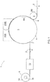
- FIG. 1 shows schematically a side view of a part of a tissue machine 1.
- the tissue machine 1 comprises a headbox for receiving fibre suspension or slush pulp from a pulping process preceding the headbox.
- the headbox supplies the fibre suspension to a wire section wherein a tissue web 2 is formed of the fibre suspension.
- a tissue web 2 is formed of the fibre suspension.
- the direction of the travel of the tissue web 2 in Figure 1 is from right to left and shown with an arrow indicated with a reference sign A.
- the tissue web 2 is forwarded to a Yankee cylinder station for drying the tissue web 2, the Yankee cylinder station providing at least a part of a drying section of the tissue machine 1.
- the Yankee cylinder station comprises a Yankee cylinder 3 the rotation direction of which is shown with an arrow indicated with a reference sign R3.
- the Yankee cylinder 3 is a large diameter cylinder filled with hot steam that heats an outer surface 4 or a cylindrical surface 4 of the Yankee cylinder 3.
- the tissue web 2 is pressed against the hot outer surface 4 of the Yankee cylinder 3 with a counter roll 5 and a press felt (not shown) travelling via the roll 5 at a nip 6 formed between the opposing Yankee cylinder 3 and counter roll 5.
- the counter roll 5 can be a suction roll, a press roll with grooved or ungrooved surface, a shoe roll or other type of an extended nip roll. Some water may be removed from the tissue web 2 due to the pressure in the nip 6 and/or a suction effect provided by the counter roll 5.
- the rotation direction of the roll 5 is shown with an arrow indicated with a reference sign R5.
- the press felt is separated from the tissue web 2 and the tissue web 2 is attached to the hot outer surface 4 of the Yankee cylinder 3.
- the hot outer surface 4 evaporates water from the tissue web 2, thereby drying the tissue web 2 further by removing from the tissue web 2 water still remaining in the web 2. Any condensation water that may arise inside the Yankee cylinder 3 is removed out from the cylinder 3.
- the tissue web 2 attached to the outer surface 4 of the Yankee cylinder 3 and travelling with the outer surface 4 of the cylinder 3 is detached from the Yankee cylinder 3 with a doctor blade 7, also called a creping doctor 7.
- the Yankee cylinder station may also comprise one or more hoods laid above the Yankee cylinder 3 next to the outer surface 4 of the cylinder 3 for blowing heated air against the tissue web 2.
- hoods laid above the Yankee cylinder 3 next to the outer surface 4 of the cylinder 3 for blowing heated air against the tissue web 2.
- Figure 1 there is a wet end side hood 8WE and a dry end side hood 8DE, the wet end side hood 8WE being the closest hood relative to the counter roll 5 in the direction of the travel or motion of the tissue web 2.
- the hood(s) it may be affected on a moisture profile of the tissue web 2 in a cross direction of the web 2.
- tissue web 2 is forwarded to the pope reel 9, where it is guided by a reeling drum (not shown) and rolled up on a reel spool 11 to form a tissue parent roll 10.
- a cross direction moisture profile of the moving tissue web 2 after the nip 6 between the counter roll 5 and the Yankee cylinder 3 but before the tissue web 2 enters into an area of an influence of the wet end side hood 8WE sets a condition for a drying performance of at least one of the counter roll 5, the Yankee cylinder 3 and the at least one hood 8WE, 8DE.
- An unequal cross direction moisture profile of the moving tissue web 2 should be equalized by controlling the operation of at least one of the counter roll 5, Yankee cylinder 3 and at least one hood 8WE, 8DE for avoiding operational problems in post processing of the tissue web 2 in a converting section of the tissue machine 1.
- the converting section is shown in Figure 1 very schematically by a box indicated with reference sign 12.
- the converting section 12 may include for example at least one of slitting, layering, perforation and/or surface texturing of the tissue web 2.
- a temperature of the moving tissue web 2 in the movement direction A of the tissue web 2 after the nip 6, wherein the tissue web 2 is already supported against the outer surface 4 of the Yankee cylinder 3 but has not yet entered into the area of the influence of the at least one hood 8WE, 8DE, is directly proportional to a dryness of the moving tissue web 2, the dryness of the moving tissue web 2 being a property of the moving tissue web 2 that directly indicates the moisture of the moving tissue web 2.
- the temperature of the moving tissue web 2 being directly proportional to the dryness of the moving tissue web 2 thus means that the higher the temperature of the moving tissue web 2, the higher the dryness of the moving tissue web 2, and consequently, the lower the moisture of the moving tissue web 2.
- the temperature of the moving tissue web 2 after the nip 6 is directly or at least substantially directly proportional to the dryness of the moving tissue web 2 right after the nip 6, whereby the temperature of the moving tissue web 2 can be used as an indicator of the moisture of the moving tissue web 2.
- the temperature of the moving tissue web 2 does not indicate the absolute value of the dryness or moisture of the moving tissue web 2.
- the absolute value of the dryness or moisture of the moving tissue web 2 would need a correlation factor that describes the exact proportionality between the temperature and the dryness or moisture of the moving tissue web 2, which correlation factor must be determined for each tissue machine and for each operating condition thereof separately.
- Figure 3 shows schematically an end view of a Yankee cylinder 3, a counter roll 5 and a measuring device 15 for measuring a cross direction temperature profile of a moving tissue web 2.
- Figure 4 shows schematically a front view of the Yankee cylinder 3, the counter roll 5 and the measuring device 15 shown in Figure 3 and Figure 5 shows schematically an upper view of the Yankee cylinder 3, the counter roll 5 and the measuring device 15 shown in Figure 3 .
- a front edge 2a and a rear edge 2b of the moving tissue web 2 are indicated in Figures 4 and 5 with broken lines.
- the property of the moving tissue web 2 to be measured is the temperature of the moving tissue web 2 whereby the measuring device 15 is used for measuring the cross direction temperature profile of the moving tissue web 2.
- the measuring device 15 according to the solution disclosed herein may, however, be also configured to be used for measuring some other property of the moving tissue web 2 as well.
- the measuring device 15 comprises a mounting bracket 16 which is preferably arranged to allow instant clamping and dismounting, i.e. quick clamping, so that the device is simple and easy to use for temporary measurements or measurements in various positions, i.e. measurement sites, in the machine 1.
- the quick clamping allows the mounting bracket 16 to be removably fastened to the counterpart at the measurement site without using any tools.
- the mounting bracket 16 is fastened to a suitable counterpart in the tissue machine 1, the counterpart thus forming an intended fastening point for the measuring device 15 in the tissue machine 1.
- the fastening point for the measuring device 15 may be provided by a counter roll bearing housing cover 13 that is supported in place by an appropriate pedestal 14.
- the counterpart forming the fastening point for the measuring device 15 may be provided by a special-purpose carriage, for example, if there is no available a suitable fastening point for the measuring device 15 at the intended measurement site in the machine.
- the mounting bracket 16 of the measuring device 15 comprises a mounting frame 17 that is to be fastened to the counter roll bearing housing cover 13.
- the mounting frame 17 may be a magnetic part as such or it may comprise a magnetic part or portion so that the mounting frame 17 may be fastened to the counter roll bearing housing cover 13 by at least a magnetic force generated between the mounting frame 17 and the counter roll bearing housing cover 13.
- the fastening of the mounting frame 17 to the counter roll bearing housing cover 13 may further be secured by at least one fastening strap 18 arranged around the counter roll bearing housing cover 13 and fastened to the opposite sides of the mounting frame 17.
- the mounting frame 17 is thus removable fastened or detachable fixable to the fastening point intended for the measuring device 15.
- a shape of the mounting bracket 16, especially a shape of a surface of the mounting frame 17 intended to be set opposite to the counter roll bearing housing cover 13, may be configured to substantially correspond to a shape of the counter roll bearing housing cover 13 in order to increase a stability of the fastening of the mounting bracket 16 to the counter roll bearing housing cover 13.
- the mounting bracket 16 further comprises a support stand 19 on top of the mounting frame 17 and being fastened to the mounting frame 17.
- the support stand 19 is fastened removable to the mounting frame 17 by bolts, for example, whereby the mounting frame 17 and the support stand 19 may be handled separately, thus decreasing the weight of parts to be handled at a time.
- the support stand 19 comprises a substantially horizontally aligned supporter 20 that is directed in the cross direction of the moving tissue web 2 but not intended to extend up to the area of the moving tissue web 2 in the tissue machine 1.
- the supporter 20 of Figures 3 to 5 is a hollow cylindrical element intended to receive an actuating member 21 and provide a support for the actuating member 21 that is arranged to run through the supporter 20 such that the actuating member 21 may be moved relative to the supporter 20 back and forth through the supporter 20 over the moving tissue web 2 in the cross direction and at a distance from the moving tissue web 2. In other words the actuating member 21 may thus be traversed relative to the supporter 20 back and forth in the cross direction of the moving tissue web 2.
- the actuating member 21 may be supported to the supporter 20 for example by ball bearing bushings arranged at the ends of the supporter 20.
- the actuating member 21 of Figures 3 to 5 is an elongated rod which has a first end 21' intended to remain on the side of the support stand 19 facing away from the moving tissue web 2 and a second end 21" intended to remain on the side of the support stand 19 facing to the moving tissue web 2.
- the first end 21' of the actuating member 21 is provided with a handhold element 22 at which a person operating the measuring device 15 may grip in order to move the actuating member 21 back and forth over the tissue web 2 in the cross direction of the web 2.
- a temperature measuring sensor 23 for measuring the temperature of the moving tissue web 2, the temperature measuring sensor 23 remaining at a distance from the surface of the moving tissue web 2.
- the temperature measuring sensor 23 moves with the actuating member 21 over the moving tissue web 2 in the cross direction thereof and measures the temperature of the web 2 at different cross-directional measurement positions P1, P2, P3, P4 for obtaining the cross direction temperature profile of the moving tissue web 2.
- the mounting bracket 16 comprises at least one fastening strap 18 for fastening the mounting bracket 16 to the counterpart forming the fastening point for the mounting bracket 16, whereby a clamping force is generated by the at least one fastening strap 18 between the mounting bracket 16 and the counterpart forming the fastening point for the mounting bracket 16 at the measurement site.
- the mounting bracket 16 may be fastened to the counterpart only by the at least one fastening strap 18, whereby the mounting bracket 16 or the mounting frame 17 thereof does not necessarily comprise any magnetic part or portion as disclosed above.
- the mounting bracket 16, the mounting frame 17 and/or the at least one fastening strap 18 may comprise tensioning devices or tensioners by which a suitable clamping force may be generated between the mounting bracket 16 or the mounting frame 17 and the at least one fastening strap 18.
- the mounting bracket 16 comprises a mounting frame 17 and at least one fastening strap 18 to be arranged around the counterpart for the measuring device 15 and fastened to opposite sides of the mounting frame 17 so as to fasten the mounting frame 17 to the counterpart by the clamping force generated by the at least one fastening strap 18 between the mounting frame 17 and the counterpart.
- the support stand 19 is fastened preferably detachably to the mounting frame 17 and comprises a supporter 20 configured to receive the actuating member 21 such that the actuating member 21 is movable relative to the supporter 20 as controlled by the controlling element.
- the mounting bracket 16 may comprise, for fastening the mounting bracket 16 to a counterpart forming the fastening point for the mounting bracket 16 at the measurement site, at least one of at least one magnetic part/portion and at least one fastening strap 18 for fastening the mounting bracket 16 to the counterpart by at least one of magnetic force and clamping force.
- the mounting bracket 16 or at least the mounting frame 17 thereof may thus be removably fastened to the counterpart with quick clamping, allowing clamping and dismounting of the mounting bracket 16 to the counterpart at the measurement site without using any tools.
- the temperature measuring sensor 23 may be an infrared temperature meter that is configured to detect the infrared radiation radiated from the moving tissue web 2, whereby the infrared radiation radiated from the moving tissue web 2 represents the temperature of the web 2.
- the infrared radiation of the moving tissue web 2 thus indicates the temperature of the moving tissue web 2 which, in turn, is directly proportional to the dryness of the moving tissue web 2 that is inversely proportional to the moisture of the moving tissue web 2.
- the handhold element 22 provides a kind of controlling element by which the movement of the actuating member 21 and the temperature measuring sensor arranged to the actuating member 21 may be controlled by hands of the person.
- the handhold element 22 may also be replaced for example with a motorized actuator to move the actuating member 21 back and forth.
- the measuring device 15 further comprises at least one position measuring sensor 24 for measuring a position of the actuating member 21 relative to the mounting bracket 16, the position measuring sensor 24 determining the cross-directional position of the temperature measuring sensor 23 associating to the respective measurement result of the temperature of the moving tissue web 2 in the cross direction of the moving tissue web 2.
- the position measuring sensor 24 may for example be an optical sensor that is used to read a scale of length 27 arranged at a surface of the actuating member 21 as schematically shown in Figure 5 .
- the measuring device 15 further comprises at least one analysis device 25 configured to receive from the temperature measuring sensor 23 the measurement results of the temperature and to receive from the position measuring sensor 24 cross-directional positions of the temperature measuring sensor 23 corresponding to the above mentioned temperature measurement results as measured by the temperature measuring sensor 23.
- at least one analysis device 25 configured to receive from the temperature measuring sensor 23 the measurement results of the temperature and to receive from the position measuring sensor 24 cross-directional positions of the temperature measuring sensor 23 corresponding to the above mentioned temperature measurement results as measured by the temperature measuring sensor 23.
- Figure 6 shows schematically an example of a possible shape of the cross direction temperature profile of the moving tissue web 2, wherein reference sign TEM P1 corresponds to the measured temperature of the moving tissue web 2 at the measurement position P1, TEM P2 corresponds to the measured temperature of the web 2 at the measurement position P2, TEM P3 corresponds to the measured temperature of the web 2 at the measurement position P3 and TEM P4 corresponds to the measured temperature of the web 2 at the measurement position P4.
- the actuating member 21 is pulled backwards to such an extent that the temperature measuring sensor 23 at the second end 21" of the actuating member 21 is positioned at the front edge 2a of the moving tissue web 2 and the position measuring sensor 24 is initialized or adjusted to zero for starting the measurement. Thereafter the person operating the measuring device 15 pushes the actuating member 21 forward across the moving tissue web 2 towards the rear edge 2b of the moving tissue web 2, i.e. in the direction of the arrow indicated with reference sign M in Figures 4 and 5 , until the temperature measuring sensor 23 has passed the rear edge 2b of the moving tissue web 2.
- the temperature measuring sensor 23 measures at certain time periods the infrared radiation radiating from the moving tissue web 2, the amount of the infrared radiation representing the temperature of the moving tissue web 2.
- a measurement of the infrared radiation at a position of the moving tissue web 2 in the cross direction thereof provides a measurement result of the temperature of the moving tissue web 2 at the respective cross-directional position of the moving tissue web 2.
- the position measuring sensor 24 measures the position of the temperature measuring sensor 23 corresponding to the respective temperature measurement of the moving tissue web 2 in the cross direction of the web 2.
- the traversing movement of the sensor 23 cross-wise over the tissue web 2 can be performed automatically by an actuator such as a step motor.
- the temperature measuring sensor 23 is configured to send the temperature measurement, referred with reference sign TEM in Figure 5 , to the analysis device 25 over a data transfer connection.
- the position measuring sensor 24 is configured to send respective measurement position of the temperature measuring sensor 23 in the cross direction of the moving tissue web 2, as measured by the position measuring sensor 24 and referred with reference sign POS in Figure 5 , to the analysis device 25 over another data transfer connection.
- the analysis device 25 comprises necessary means for receiving and allocating the measured temperatures of the moving tissue web 2 with the respective measurement cross-directional positions of the temperature measuring device 23 for forming the cross direction temperature profile of the moving tissue web 2.
- These means may comprise a necessary number of memory elements for storing the temperature measurement information and the position measurement information and at least one microprocessor or a similar processing element for executing a computer program product for formation of the cross directional temperature profile of the moving tissue web 2, as shown for example in Figures 2a, 2b and 6 .
- the analysis device 25 may further comprise a display unit for displaying the measured temperature values and the temperature profile.
- the analysis device 25 may for example be a portable computer.
- the actual number of the measurement positions or points in the cross direction of the moving tissue web 2 and their exact positions in the cross direction of the moving tissue web 2 may vary in many ways between different measurement procedures. They may depend for example on a speed how fast the actuating member 21 and the temperature measuring sensor 23 arranged thereto is moved in the cross direction of the moving tissue web 2, the response time of the temperature measurement sensor 23, i.e. the time needed by the temperature measurement sensor 23 to complete the single temperature measurement of the moving tissue web 2, and a width of the moving tissue web 2.
- the shape of the cross directional temperature profile of the moving tissue web 2 indicates the shape of the cross directional dryness profile of the moving tissue web 2. Therefore the presentation of the shape of the cross directional temperature profile of the moving tissue web 2 presents in practice also the shape of the cross directional dryness profile of the moving tissue web 2 and no conversion of the shape of the cross directional temperature profile of the moving tissue web to the shape of the cross directional dryness profile of the moving tissue web by the analysis device 25 is necessarily needed. If it is preferred to present the shape of the cross directional moisture profile of the moving tissue web, it may be provided by an inverse of the shape of the cross directional temperature profile of the moving tissue web 2 as carried out by the analysis device 25.
- the measuring device 15 may include a signal conversion device 26 allocated between the analysis device 25 and the temperature measuring sensor 23 and the position measuring sensor 24.
- the signal conversion device 26 may include a converter for providing possibly needed signal conversion between analogue and digital signal formats so as to provide a signal format suitable to be received by the analysis device or an accessory connected thereto.
- the signal conversion device 26 may comprise amplifying means for amplifying the measuring signals received from the temperature measuring sensor 23 and the position measuring sensor 24.
- the signal conversion device 26 is shown schematically in Figure 5 with a box drawn with a broken line.
- the measuring device 15 disclosed provides a measuring device that may be moved or transferred from one measurement site in the tissue machine 1 to another measurement site and which measuring device 15 may be located in the tissue machine 1 at a desired location wherein a property of the moving tissue web 2 is intended to be temporarily measured.
- An introduction of the measuring device 15 for providing the measurement operation and a dismantlement of the measuring device 15 after carrying out of the measurement operation is easy.
- the measuring device 15 disclosed herein allows the measurement of the properties of the moving tissue web 2 in locations or places in the tissue machine 1 wherein it is very difficult or unsafe or unprofitable to organize the measurement operation in another way.
- the measuring device 15 is especially suitable for determining the cross directional moisture profile of the moving tissue web after the nip 6 between the Yankee cylinder 3 and the counter roll 5 before the tissue web 2 enters to the influence area of the hood arranged next to the Yankee cylinder.
- the measuring device disclosed there is no need to take physical samples of the tissue web 2 for determining the cross directional moisture profile of the moving tissue web 2, i.e. there is no need to any physical interaction with the moving tissue web 2.
- the measurement procedure provided by the measuring device 15 disclosed is thus safe for the personnel carrying out the measurement. Because of no physical interaction with the moving tissue web 2 the production of the tissue web 2 is not affected at all whereby no production of the tissue web 2 is lost.
- Figure 7 shows schematically a side view of a part of another embodiment of a measuring device 15.
- the measuring device 15 of Figure 7 may comprise all the parts already disclosed above but the mounting frame 17, mounting strap 18 and the signal conversion device 26 have been omitted in Figure 7 .
- the actuating member 21 in Figure 7 comprises two coaxial actuating member parts, i.e. an inner actuating member part 21a having a form of an elongated rod or pipe and being arranged inside of an outer actuating member part 21b and supported thereto by ball bearing bushings 28, for example, the outer actuating member 21b having a form of an elongated tube or pipe.
- the handhold element 22 is arranged to the inner actuating member part 21 at the first end 21' of the actuating member 21 and the temperature measuring sensor 23 is arranged to the inner actuating member part 21 at the second end 21" of the inner actuating member part 21a.
- the supporter 20 is provided with a length scale measurement window 29 through which the length scale 27 is visible and at which the position measuring sensor 24 may also be arranged to.
- the outer actuating member part 21b When the measuring device 15 of Figure 7 is operated, the outer actuating member part 21b is pulled into a back position in the cross direction of the moving tissue web 2, i.e. to the left in Figure 7 , and locked at that position.
- the locking has not been disclosed in Figure 7 for the sake of clarity but it may be arranged for example between the outer actuating member part 21b and the supporter 20 in a manner evident for a person skilled in the art.
- the inner actuating member part 21a is moved relative to the outer actuating member part 21b such that the temperature measuring sensor 23 is at the front edge 2a of the moving tissue web 2, and the inner actuating member part 21a is locked relative to the outer actuating member part 21b.
- the locking of the outer actuating member part 21b is released or loosed whereby the outer actuating member part 21b and the inner actuating member part 21a and the temperature measuring sensor 23 arranged to the inner actuating member part 21a are able to move together with the outer actuating member part 21b in the cross direction of the moving tissue web 2.
- the inner actuating member part 21a and the temperature measuring sensor 23 arranged to the inner actuating member part 21a thus also moves together with the outer actuating member part 21b in the cross direction of the moving tissue web 2, whereby the temperature measurement sensor 23 measures the temperature of the moving tissue web 2 in a number of cross directional positions of the web 2 and the position measuring sensor 24 determines the cross directional measurement positions of the temperature measuring sensor 23 associating to the respective measurement results determined by the temperature measurement sensor 23.
- the operator of the measuring device 15 may also stop the movement of the outer actuating member part 21b so that the temperature measuring sensor 23 may stay at a desired position in the cross direction of the moving tissue web 2 for a longer time. That position information may be retrieved either by inspecting the length scale through the length scale measurement window 29 or on the basis of the position information provided by the position measuring sensor 24.
- the inner 21a and the outer 21b actuating member parts are moved as far away from the moving tissue web 2 as possible in the cross direction of the moving tissue web 2 and locked in that position, and thereafter the measuring device 15 is dismantled from its fastening point or location.
- the measuring device 15 may include more than one measuring sensor arranged to the actuating member 21 for measuring more than only one property of the moving tissue web 2 simultaneously.
- the measuring device is described in connection with a tissue machine, but naturally it is applicable in other fibre web machines intended for manufacturing lignocellulose-containing fibre webs, such as paper machines and board machines.
- the property of the moving tissue web to be measured may be some other than the temperature of the web.
Landscapes
- Physics & Mathematics (AREA)
- Chemical & Material Sciences (AREA)
- Health & Medical Sciences (AREA)
- Life Sciences & Earth Sciences (AREA)
- Biochemistry (AREA)
- Analytical Chemistry (AREA)
- General Health & Medical Sciences (AREA)
- General Physics & Mathematics (AREA)
- Immunology (AREA)
- Pathology (AREA)
- Electromagnetism (AREA)
- Engineering & Computer Science (AREA)
- Food Science & Technology (AREA)
- Medicinal Chemistry (AREA)
- Paper (AREA)
Abstract
Description
- The present invention relates to a method for determining a cross direction profile of a property of a moving lignocellulose-containing fibre web in a fibre web machine.
- The present invention relates also to a device for determining a cross direction profile of a property of a moving lignocellulose-containing fibre web in a fibre web machine.
- One of the most complex parts of a manufacturing chain of a tissue web is a drying section of a tissue machine. The drying section of the tissue machine comprises a Yankee cylinder that is used for drying the tissue web to be manufactured. The Yankee cylinder comprises a heated outer surface against which the tissue web to be manufactured is brought for drying the web. In a direction of a motion of the tissue web the Yankee cylinder is preceded by a counter roll that presses the moving tissue web against the outer surface of the Yankee cylinder. The drying section of the tissue web comprises typically also at least one hood for blowing heated air against the tissue web supported to the outer surface of the Yankee cylinder, the hood being located above the Yankee, i.e. after a nip formed between the counter roll and the Yankee cylinder in the direction of the motion of the tissue web.
- A moisture of the moving tissue web is one property of the moving tissue web as a point of interest in the manufacturing of the tissue web. A cross direction moisture profile of the moving tissue web especially at a location right after the nip between the counter roll and the Yankee cylinder before the tissue web enters into an area of an influence of the hood sets a condition for a drying performance to be provided by at least one of the counter roll, the Yankee cylinder and the hood. An unequal cross direction moisture profile of the moving tissue web should be equalized by controlling the operation of the at least one of the counter roll, Yankee cylinder and hood for avoiding operational problems in a post processing of the tissue web in a converting section of the tissue machine, including for example at least one of slitting, layering, perforation and/or surface texturing of the tissue web.
- Presently the cross direction moisture profile of the moving tissue web at the location right after the nip between the counter roll and the Yankee cylinder before the tissue web enters into the influence area of the hood is determined by taking physical samples of the moving tissue web from the Yankee cylinder surface by manual means. This is called a scraping of the sample. The wet weight of the carefully preserved sample is determined, the sample is dried in a heated oven for a certain period of time, such as 12 to 24 hours, until all water is vaporized away from the sample, and then its dry weight is determined. The moisture content of the sample may then be determined by the wet weight and the dry weight of the sample. When this procedure is carried out for a number of samples scraped at different positions in the cross direction of the tissue web, the cross direction moisture profile of the tissue web is obtained.
- One disadvantage of this method to determine the cross direction moisture profile of the tissue web is a very long, even more than 24 hours, response time - so in fact the moisture profile thus obtained is the profile from yesterday and efforts to affect it may be incorrect for today's operational condition of the tissue machine. Another disadvantage is a need to use a manually operated mechanical tool to scrape the samples from the tissue web supported on the Yankee cylinder surface, which is unsafe for a person taking the sample because he/she has to approach closely to the machine section operating with a high speed and at elevated temperatures. The scraping of the physical samples from the moving tissue web also breaks the uniform structure of the moving tissue web and thus leads to a loss of production of the tissue web produced during the sampling.
- An object of the present invention is to provide a novel method and device for determining a cross direction profile of a property of a moving lignocellulose-containing fibre web in a fibre web machine.
- The invention is characterized by the features of the independent claims.
- The invention is based on the idea of determining a cross direction profile of a property of a moving fibre web with a measuring device that is traversable in the cross direction of the moving fibre web but easily movable to a desired measurement site at a fibre web machine. The measuring device comprises a property measuring sensor movable in a cross direction of the moving fibre web and configured to determine a measurement result representing the property of the web at a number of cross directional measurement positions in response to a movement of the property measuring sensor in the cross direction of the moving fibre web, a position measuring sensor configured to determine a measurement position of the property measuring sensor associating to the respective measurement result of the property of the moving fibre web in the cross direction of the web, and an analysis device for receiving the measurement results representing the property of the moving fibre web and the respective measurement positions and for allocating the measurement results of the property of the moving fibre web with the respective cross directional measurement positions of the property measuring sensor for forming the cross direction profile of the property of the moving fibre web. The measuring device further comprises a mounting bracket that is detachable fixable with quick clamping for fastening the measuring device at a desired measurement site in the fibre web machine.
- An advantage of the invention is that the measuring device disclosed is traversable across the web and thanks to the quick clamping may be moved from one measurement location to another measurement location, whereby it may be located in the fibre web machine at the desired location where a property of the moving lignocellulose-containing fibre web is intended to be temporarily measured. The measuring device allows to measure the properties of the moving fibre web in locations or places in the fibre web machine where it is very difficult or unsafe or unprofitable to organize the measurement operation in another way.
- Some embodiments of the invention are disclosed in the dependent claims.
- In the following the invention will be described in greater detail by means of preferred embodiments with reference to the accompanying drawings, in which
-
Figure 1 shows schematically a side view of a part of a tissue machine and a Yankee cylinder therein; -
Figures 2a and 2b show schematically two different comparison measurement tests between a temperature and a dryness of a moving tissue web; -
Figure 3 shows schematically an end view of a Yankee cylinder, a counter roll and a measuring device for measuring a cross direction temperature profile of a moving tissue web; -
Figure 4 shows schematically a front view of the Yankee cylinder, the counter roll and the measuring device shown inFigure 3 , -
Figure 5 shows schematically an upper view of the Yankee cylinder, the counter roll and the measuring device shown inFigure 3 ; -
Figure 6 shows schematically an example of a shape of a cross direction temperature profile of a moving tissue web; and -
Figure 7 shows schematically a side view of a part of another embodiment of a measuring device. - For the sake of clarity, the figures show some embodiments of the invention in a simplified manner. Like reference numerals identify like elements in the Figures.
-
Figure 1 shows schematically a side view of a part of atissue machine 1. Thetissue machine 1 comprises a headbox for receiving fibre suspension or slush pulp from a pulping process preceding the headbox. The headbox supplies the fibre suspension to a wire section wherein atissue web 2 is formed of the fibre suspension. For the sake of clarity, the pulping process, the headbox, the wire section and any possible devices therein are not disclosed in the Figures but their general structures and operations are known for a person skilled in the art. The direction of the travel of thetissue web 2 inFigure 1 is from right to left and shown with an arrow indicated with a reference sign A. - From the wire section the
tissue web 2 is forwarded to a Yankee cylinder station for drying thetissue web 2, the Yankee cylinder station providing at least a part of a drying section of thetissue machine 1. The Yankee cylinder station comprises a Yankeecylinder 3 the rotation direction of which is shown with an arrow indicated with a reference sign R3. The Yankeecylinder 3 is a large diameter cylinder filled with hot steam that heats anouter surface 4 or acylindrical surface 4 of the Yankeecylinder 3. - The
tissue web 2 is pressed against the hotouter surface 4 of the Yankeecylinder 3 with acounter roll 5 and a press felt (not shown) travelling via theroll 5 at anip 6 formed between the opposing Yankeecylinder 3 andcounter roll 5. Thecounter roll 5 can be a suction roll, a press roll with grooved or ungrooved surface, a shoe roll or other type of an extended nip roll. Some water may be removed from thetissue web 2 due to the pressure in thenip 6 and/or a suction effect provided by thecounter roll 5. The rotation direction of theroll 5 is shown with an arrow indicated with a reference sign R5. - After the
nip 6 the press felt is separated from thetissue web 2 and thetissue web 2 is attached to the hotouter surface 4 of the Yankeecylinder 3. The hotouter surface 4 evaporates water from thetissue web 2, thereby drying thetissue web 2 further by removing from thetissue web 2 water still remaining in theweb 2. Any condensation water that may arise inside the Yankeecylinder 3 is removed out from thecylinder 3. Thetissue web 2 attached to theouter surface 4 of the Yankeecylinder 3 and travelling with theouter surface 4 of thecylinder 3 is detached from the Yankeecylinder 3 with a doctor blade 7, also called a creping doctor 7. - The Yankee cylinder station may also comprise one or more hoods laid above the Yankee
cylinder 3 next to theouter surface 4 of thecylinder 3 for blowing heated air against thetissue web 2. InFigure 1 there is a wet end side hood 8WE and a dry end side hood 8DE, the wet end side hood 8WE being the closest hood relative to thecounter roll 5 in the direction of the travel or motion of thetissue web 2. By the hood(s) it may be affected on a moisture profile of thetissue web 2 in a cross direction of theweb 2. - From the Yankee
cylinder 3 thetissue web 2 is forwarded to thepope reel 9, where it is guided by a reeling drum (not shown) and rolled up on areel spool 11 to form atissue parent roll 10. - A cross direction moisture profile of the moving
tissue web 2 after thenip 6 between thecounter roll 5 and the Yankeecylinder 3 but before thetissue web 2 enters into an area of an influence of the wet end side hood 8WE sets a condition for a drying performance of at least one of thecounter roll 5, the Yankeecylinder 3 and the at least one hood 8WE, 8DE. An unequal cross direction moisture profile of the movingtissue web 2 should be equalized by controlling the operation of at least one of thecounter roll 5, Yankeecylinder 3 and at least one hood 8WE, 8DE for avoiding operational problems in post processing of thetissue web 2 in a converting section of thetissue machine 1. For example, linear load of thecounter roll 5 at thenip 6, blow velocity of the hoods 8WE, 8DE, condensate removal from the Yankeecylinder 3 and other cross-machine adjustable controls are among those control methods by which the cross profile uniformity of thetissue web 2 can be adjusted. The converting section is shown inFigure 1 very schematically by a box indicated withreference sign 12. The convertingsection 12 may include for example at least one of slitting, layering, perforation and/or surface texturing of thetissue web 2. - It has been found out that a temperature of the moving
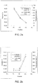
tissue web 2 in the movement direction A of thetissue web 2 after thenip 6, wherein thetissue web 2 is already supported against theouter surface 4 of theYankee cylinder 3 but has not yet entered into the area of the influence of the at least one hood 8WE, 8DE, is directly proportional to a dryness of the movingtissue web 2, the dryness of the movingtissue web 2 being a property of the movingtissue web 2 that directly indicates the moisture of the movingtissue web 2. The temperature of the movingtissue web 2 being directly proportional to the dryness of the movingtissue web 2 thus means that the higher the temperature of the movingtissue web 2, the higher the dryness of the movingtissue web 2, and consequently, the lower the moisture of the movingtissue web 2. This has been shown inFigures 2a and 2b , wherein it has been disclosed cross direction temperature and dryness profiles of the movingtissue web 2 obtained as a result of two different comparison measurement tests between the temperature and the dryness of the movingtissue web 2 right after a nip 6 in atissue machine 1 before thetissue web 2 enters into the influence area of the at least one hood 8WE, 8DE. In the measurement tests ofFigures 2a, 2b the temperature of the movingtissue web 2 has been measured by a pyrometer measuring infrared radiation radiating from the movingtissue web 2 when theweb 2 has been supported against an outer surface of aYankee cylinder 3 and the dryness of the movingtissue web 2 has been determined by scraping samples off the movingtissue web 2 and weighting and drying them in the way disclosed above in the section "Background of the invention". The comparison measurements tests were carried out in three different cross direction positions of the movingtissue web 2, i.e. positions "P1", "P2" and "P3" indicated inFigures 2a, 2b . The comparison measurements tests were carried out in the same tissue machine but in different days. - On the basis of
Figures 2a and 2b it can be verified that the temperature of the movingtissue web 2 after thenip 6 is directly or at least substantially directly proportional to the dryness of the movingtissue web 2 right after thenip 6, whereby the temperature of the movingtissue web 2 can be used as an indicator of the moisture of the movingtissue web 2. It may be emphasized herein that the temperature of the movingtissue web 2 does not indicate the absolute value of the dryness or moisture of the movingtissue web 2. The absolute value of the dryness or moisture of the movingtissue web 2 would need a correlation factor that describes the exact proportionality between the temperature and the dryness or moisture of the movingtissue web 2, which correlation factor must be determined for each tissue machine and for each operating condition thereof separately. However, as long as only a shape - most often the uniformity - of the cross direction profile of the dryness or moisture of the moving tissue web is under interest, while absolute or exact values of the dryness or moisture are not under interest, it is sufficient to use the shape of the cross direction profile of the temperature to represent the shape of the cross direction profile of the dryness or moisture of the movingtissue web 2. -
Figure 3 shows schematically an end view of aYankee cylinder 3, acounter roll 5 and a measuringdevice 15 for measuring a cross direction temperature profile of a movingtissue web 2.Figure 4 shows schematically a front view of theYankee cylinder 3, thecounter roll 5 and the measuringdevice 15 shown inFigure 3 andFigure 5 shows schematically an upper view of theYankee cylinder 3, thecounter roll 5 and the measuringdevice 15 shown inFigure 3 . Afront edge 2a and arear edge 2b of the movingtissue web 2 are indicated inFigures 4 and5 with broken lines. In the example ofFigures 3 to 5 , and later in the example ofFigure 6 , it is thus assumed that the property of the movingtissue web 2 to be measured is the temperature of the movingtissue web 2 whereby the measuringdevice 15 is used for measuring the cross direction temperature profile of the movingtissue web 2. The measuringdevice 15 according to the solution disclosed herein may, however, be also configured to be used for measuring some other property of the movingtissue web 2 as well. - The measuring
device 15 comprises a mountingbracket 16 which is preferably arranged to allow instant clamping and dismounting, i.e. quick clamping, so that the device is simple and easy to use for temporary measurements or measurements in various positions, i.e. measurement sites, in themachine 1. The quick clamping allows the mountingbracket 16 to be removably fastened to the counterpart at the measurement site without using any tools. The mountingbracket 16 is fastened to a suitable counterpart in thetissue machine 1, the counterpart thus forming an intended fastening point for the measuringdevice 15 in thetissue machine 1. When the temperature of the movingtissue web 2 is to be measured right after the nip 6 at a location where the movingtissue web 2 is supported on theouter surface 4 of theYankee cylinder 3 but before thetissue web 2 enters the influence area of the wet end side hood 8WE, the fastening point for the measuringdevice 15 may be provided by a counter roll bearinghousing cover 13 that is supported in place by anappropriate pedestal 14. Alternatively the counterpart forming the fastening point for the measuringdevice 15 may be provided by a special-purpose carriage, for example, if there is no available a suitable fastening point for the measuringdevice 15 at the intended measurement site in the machine. - The mounting
bracket 16 of the measuringdevice 15 comprises a mountingframe 17 that is to be fastened to the counter roll bearinghousing cover 13. The mountingframe 17 may be a magnetic part as such or it may comprise a magnetic part or portion so that the mountingframe 17 may be fastened to the counter roll bearinghousing cover 13 by at least a magnetic force generated between the mountingframe 17 and the counter roll bearinghousing cover 13. The fastening of the mountingframe 17 to the counter roll bearinghousing cover 13 may further be secured by at least onefastening strap 18 arranged around the counter roll bearinghousing cover 13 and fastened to the opposite sides of the mountingframe 17. The mountingframe 17 is thus removable fastened or detachable fixable to the fastening point intended for the measuringdevice 15. A shape of the mountingbracket 16, especially a shape of a surface of the mountingframe 17 intended to be set opposite to the counter roll bearinghousing cover 13, may be configured to substantially correspond to a shape of the counter roll bearinghousing cover 13 in order to increase a stability of the fastening of the mountingbracket 16 to the counter roll bearinghousing cover 13. - The mounting
bracket 16 further comprises asupport stand 19 on top of the mountingframe 17 and being fastened to the mountingframe 17. Preferably thesupport stand 19 is fastened removable to the mountingframe 17 by bolts, for example, whereby the mountingframe 17 and the support stand 19 may be handled separately, thus decreasing the weight of parts to be handled at a time. - The support stand 19 comprises a substantially horizontally aligned
supporter 20 that is directed in the cross direction of the movingtissue web 2 but not intended to extend up to the area of the movingtissue web 2 in thetissue machine 1. Thesupporter 20 ofFigures 3 to 5 is a hollow cylindrical element intended to receive an actuatingmember 21 and provide a support for the actuatingmember 21 that is arranged to run through thesupporter 20 such that the actuatingmember 21 may be moved relative to thesupporter 20 back and forth through thesupporter 20 over the movingtissue web 2 in the cross direction and at a distance from the movingtissue web 2. In other words the actuatingmember 21 may thus be traversed relative to thesupporter 20 back and forth in the cross direction of the movingtissue web 2. The actuatingmember 21 may be supported to thesupporter 20 for example by ball bearing bushings arranged at the ends of thesupporter 20. - The actuating
member 21 ofFigures 3 to 5 is an elongated rod which has a first end 21' intended to remain on the side of the support stand 19 facing away from the movingtissue web 2 and asecond end 21" intended to remain on the side of the support stand 19 facing to the movingtissue web 2. The first end 21' of the actuatingmember 21 is provided with ahandhold element 22 at which a person operating the measuringdevice 15 may grip in order to move the actuatingmember 21 back and forth over thetissue web 2 in the cross direction of theweb 2. At thesecond end 21" of the actuatingmember 21 there is atemperature measuring sensor 23 for measuring the temperature of the movingtissue web 2, thetemperature measuring sensor 23 remaining at a distance from the surface of the movingtissue web 2. When the person operating the measuringdevice 15 moves the actuatingmember 21 across the movingtissue web 2, thetemperature measuring sensor 23 moves with the actuatingmember 21 over the movingtissue web 2 in the cross direction thereof and measures the temperature of theweb 2 at different cross-directional measurement positions P1, P2, P3, P4 for obtaining the cross direction temperature profile of the movingtissue web 2. - According to an embodiment the mounting
bracket 16 comprises at least onefastening strap 18 for fastening the mountingbracket 16 to the counterpart forming the fastening point for the mountingbracket 16, whereby a clamping force is generated by the at least onefastening strap 18 between the mountingbracket 16 and the counterpart forming the fastening point for the mountingbracket 16 at the measurement site. According to this embodiment the mountingbracket 16 may be fastened to the counterpart only by the at least onefastening strap 18, whereby the mountingbracket 16 or the mountingframe 17 thereof does not necessarily comprise any magnetic part or portion as disclosed above. The mountingbracket 16, the mountingframe 17 and/or the at least onefastening strap 18 may comprise tensioning devices or tensioners by which a suitable clamping force may be generated between the mountingbracket 16 or the mountingframe 17 and the at least onefastening strap 18. - According to an embodiment the mounting
bracket 16 comprises a mountingframe 17 and at least onefastening strap 18 to be arranged around the counterpart for the measuringdevice 15 and fastened to opposite sides of the mountingframe 17 so as to fasten the mountingframe 17 to the counterpart by the clamping force generated by the at least onefastening strap 18 between the mountingframe 17 and the counterpart. Furthermore, thesupport stand 19 is fastened preferably detachably to the mountingframe 17 and comprises asupporter 20 configured to receive the actuatingmember 21 such that the actuatingmember 21 is movable relative to thesupporter 20 as controlled by the controlling element. - Thus, the mounting
bracket 16 may comprise, for fastening the mountingbracket 16 to a counterpart forming the fastening point for the mountingbracket 16 at the measurement site, at least one of at least one magnetic part/portion and at least onefastening strap 18 for fastening the mountingbracket 16 to the counterpart by at least one of magnetic force and clamping force. The mountingbracket 16 or at least the mountingframe 17 thereof may thus be removably fastened to the counterpart with quick clamping, allowing clamping and dismounting of the mountingbracket 16 to the counterpart at the measurement site without using any tools. - The
temperature measuring sensor 23 may be an infrared temperature meter that is configured to detect the infrared radiation radiated from the movingtissue web 2, whereby the infrared radiation radiated from the movingtissue web 2 represents the temperature of theweb 2. The infrared radiation of the movingtissue web 2 thus indicates the temperature of the movingtissue web 2 which, in turn, is directly proportional to the dryness of the movingtissue web 2 that is inversely proportional to the moisture of the movingtissue web 2. - The
handhold element 22 provides a kind of controlling element by which the movement of the actuatingmember 21 and the temperature measuring sensor arranged to the actuatingmember 21 may be controlled by hands of the person. Thehandhold element 22 may also be replaced for example with a motorized actuator to move the actuatingmember 21 back and forth. - The measuring
device 15 further comprises at least oneposition measuring sensor 24 for measuring a position of the actuatingmember 21 relative to the mountingbracket 16, theposition measuring sensor 24 determining the cross-directional position of thetemperature measuring sensor 23 associating to the respective measurement result of the temperature of the movingtissue web 2 in the cross direction of the movingtissue web 2. Theposition measuring sensor 24 may for example be an optical sensor that is used to read a scale oflength 27 arranged at a surface of the actuatingmember 21 as schematically shown inFigure 5 . - The measuring
device 15 further comprises at least oneanalysis device 25 configured to receive from thetemperature measuring sensor 23 the measurement results of the temperature and to receive from theposition measuring sensor 24 cross-directional positions of thetemperature measuring sensor 23 corresponding to the above mentioned temperature measurement results as measured by thetemperature measuring sensor 23. By allocating the temperature measurement results as measured by thetemperature measuring sensor 23 with the respective cross-directional positions of thetemperature measuring sensor 23 as indicated by theposition measuring sensor 24 the cross direction profile of the temperature of the movingtissue web 2 may be formed.Figure 6 shows schematically an example of a possible shape of the cross direction temperature profile of the movingtissue web 2, wherein reference sign TEMP1 corresponds to the measured temperature of the movingtissue web 2 at the measurement position P1, TEMP2 corresponds to the measured temperature of theweb 2 at the measurement position P2, TEMP3 corresponds to the measured temperature of theweb 2 at the measurement position P3 and TEMP4 corresponds to the measured temperature of theweb 2 at the measurement position P4. - At the beginning of the measurement operation the actuating
member 21 is pulled backwards to such an extent that thetemperature measuring sensor 23 at thesecond end 21" of the actuatingmember 21 is positioned at thefront edge 2a of the movingtissue web 2 and theposition measuring sensor 24 is initialized or adjusted to zero for starting the measurement. Thereafter the person operating the measuringdevice 15 pushes the actuatingmember 21 forward across the movingtissue web 2 towards therear edge 2b of the movingtissue web 2, i.e. in the direction of the arrow indicated with reference sign M inFigures 4 and 5 , until thetemperature measuring sensor 23 has passed therear edge 2b of the movingtissue web 2. At the same time when thetemperature measuring sensor 23 travels over the movingtissue web 2 thetemperature measuring sensor 23 measures at certain time periods the infrared radiation radiating from the movingtissue web 2, the amount of the infrared radiation representing the temperature of the movingtissue web 2. A measurement of the infrared radiation at a position of the movingtissue web 2 in the cross direction thereof provides a measurement result of the temperature of the movingtissue web 2 at the respective cross-directional position of the movingtissue web 2. At the same time theposition measuring sensor 24 measures the position of thetemperature measuring sensor 23 corresponding to the respective temperature measurement of the movingtissue web 2 in the cross direction of theweb 2. As mentioned earlier the traversing movement of thesensor 23 cross-wise over thetissue web 2 can be performed automatically by an actuator such as a step motor. - The
temperature measuring sensor 23 is configured to send the temperature measurement, referred with reference sign TEM inFigure 5 , to theanalysis device 25 over a data transfer connection. Theposition measuring sensor 24 is configured to send respective measurement position of thetemperature measuring sensor 23 in the cross direction of the movingtissue web 2, as measured by theposition measuring sensor 24 and referred with reference sign POS inFigure 5 , to theanalysis device 25 over another data transfer connection. Theanalysis device 25 comprises necessary means for receiving and allocating the measured temperatures of the movingtissue web 2 with the respective measurement cross-directional positions of thetemperature measuring device 23 for forming the cross direction temperature profile of the movingtissue web 2. These means may comprise a necessary number of memory elements for storing the temperature measurement information and the position measurement information and at least one microprocessor or a similar processing element for executing a computer program product for formation of the cross directional temperature profile of the movingtissue web 2, as shown for example inFigures 2a, 2b and6 . Theanalysis device 25 may further comprise a display unit for displaying the measured temperature values and the temperature profile. Theanalysis device 25 may for example be a portable computer. - It should be noted that the actual number of the measurement positions or points in the cross direction of the moving
tissue web 2 and their exact positions in the cross direction of the movingtissue web 2 may vary in many ways between different measurement procedures. They may depend for example on a speed how fast the actuatingmember 21 and thetemperature measuring sensor 23 arranged thereto is moved in the cross direction of the movingtissue web 2, the response time of thetemperature measurement sensor 23, i.e. the time needed by thetemperature measurement sensor 23 to complete the single temperature measurement of the movingtissue web 2, and a width of the movingtissue web 2. It is also possible to stop the movement of thetemperature measurement sensor 23 at any desired position in the cross direction of the movingtissue web 2 so that a number of single measurement results of the temperature of the movingtissue web 2 at a desired cross directional position of the movingtissue web 2 are obtained. In this way it is also possible to determine a temperature profile of the movingtissue web 2 in the longitudinal direction thereof at any desired position in the cross direction of the movingtissue web 2. - Because the determined cross directional temperature profile of the moving
tissue web 2 is directly proportional to the cross directional dryness profile of the movingtissue web 2, the shape of the cross directional temperature profile of the movingtissue web 2 indicates the shape of the cross directional dryness profile of the movingtissue web 2. Therefore the presentation of the shape of the cross directional temperature profile of the movingtissue web 2 presents in practice also the shape of the cross directional dryness profile of the movingtissue web 2 and no conversion of the shape of the cross directional temperature profile of the moving tissue web to the shape of the cross directional dryness profile of the moving tissue web by theanalysis device 25 is necessarily needed. If it is preferred to present the shape of the cross directional moisture profile of the moving tissue web, it may be provided by an inverse of the shape of the cross directional temperature profile of the movingtissue web 2 as carried out by theanalysis device 25. - Additionally the measuring
device 15 may include asignal conversion device 26 allocated between theanalysis device 25 and thetemperature measuring sensor 23 and theposition measuring sensor 24. Thesignal conversion device 26 may include a converter for providing possibly needed signal conversion between analogue and digital signal formats so as to provide a signal format suitable to be received by the analysis device or an accessory connected thereto. Instead of that or in addition to that thesignal conversion device 26 may comprise amplifying means for amplifying the measuring signals received from thetemperature measuring sensor 23 and theposition measuring sensor 24. Thesignal conversion device 26 is shown schematically inFigure 5 with a box drawn with a broken line. - The measuring
device 15 disclosed provides a measuring device that may be moved or transferred from one measurement site in thetissue machine 1 to another measurement site and which measuringdevice 15 may be located in thetissue machine 1 at a desired location wherein a property of the movingtissue web 2 is intended to be temporarily measured. An introduction of the measuringdevice 15 for providing the measurement operation and a dismantlement of the measuringdevice 15 after carrying out of the measurement operation is easy. The measuringdevice 15 disclosed herein allows the measurement of the properties of the movingtissue web 2 in locations or places in thetissue machine 1 wherein it is very difficult or unsafe or unprofitable to organize the measurement operation in another way. - The measuring
device 15 is especially suitable for determining the cross directional moisture profile of the moving tissue web after the nip 6 between theYankee cylinder 3 and thecounter roll 5 before thetissue web 2 enters to the influence area of the hood arranged next to the Yankee cylinder. With the measuring device disclosed there is no need to take physical samples of thetissue web 2 for determining the cross directional moisture profile of the movingtissue web 2, i.e. there is no need to any physical interaction with the movingtissue web 2. The measurement procedure provided by the measuringdevice 15 disclosed is thus safe for the personnel carrying out the measurement. Because of no physical interaction with the movingtissue web 2 the production of thetissue web 2 is not affected at all whereby no production of thetissue web 2 is lost. -
Figure 7 shows schematically a side view of a part of another embodiment of a measuringdevice 15. The measuringdevice 15 ofFigure 7 may comprise all the parts already disclosed above but the mountingframe 17, mountingstrap 18 and thesignal conversion device 26 have been omitted inFigure 7 . The actuatingmember 21 inFigure 7 comprises two coaxial actuating member parts, i.e. an inneractuating member part 21a having a form of an elongated rod or pipe and being arranged inside of an outeractuating member part 21b and supported thereto byball bearing bushings 28, for example, theouter actuating member 21b having a form of an elongated tube or pipe. Thehandhold element 22 is arranged to the inneractuating member part 21 at the first end 21' of the actuatingmember 21 and thetemperature measuring sensor 23 is arranged to the inneractuating member part 21 at thesecond end 21" of the inneractuating member part 21a. Thesupporter 20 is provided with a lengthscale measurement window 29 through which thelength scale 27 is visible and at which theposition measuring sensor 24 may also be arranged to. - When the measuring
device 15 ofFigure 7 is operated, the outeractuating member part 21b is pulled into a back position in the cross direction of the movingtissue web 2, i.e. to the left inFigure 7 , and locked at that position. The locking has not been disclosed inFigure 7 for the sake of clarity but it may be arranged for example between the outeractuating member part 21b and thesupporter 20 in a manner evident for a person skilled in the art. Thereafter the inneractuating member part 21a is moved relative to the outeractuating member part 21b such that thetemperature measuring sensor 23 is at thefront edge 2a of the movingtissue web 2, and the inneractuating member part 21a is locked relative to the outeractuating member part 21b. The locking between the inner 21a and the outer 21b actuating member parts has not been disclosed inFigure 7 for the sake of clarity but it may arranged by several ways evident for a person skilled in the art. When the inner 21a and the outer 21b actuating member parts have been locked to each other in a position wherein thetemperature measuring sensor 23 is at thefront edge 2a of the movingtissue web 2, theposition measuring sensor 24 is initialized or adjusted to zero relative to thelength scale 27 for starting the measurement. - For starting the actual measurement the locking of the outer
actuating member part 21b is released or loosed whereby the outeractuating member part 21b and the inneractuating member part 21a and thetemperature measuring sensor 23 arranged to the inneractuating member part 21a are able to move together with the outeractuating member part 21b in the cross direction of the movingtissue web 2. When the outeractuating member part 21b is moved in the cross direction of the movingtissue web 2, the inneractuating member part 21a and thetemperature measuring sensor 23 arranged to the inneractuating member part 21a thus also moves together with the outeractuating member part 21b in the cross direction of the movingtissue web 2, whereby thetemperature measurement sensor 23 measures the temperature of the movingtissue web 2 in a number of cross directional positions of theweb 2 and theposition measuring sensor 24 determines the cross directional measurement positions of thetemperature measuring sensor 23 associating to the respective measurement results determined by thetemperature measurement sensor 23. The operator of the measuringdevice 15 may also stop the movement of the outeractuating member part 21b so that thetemperature measuring sensor 23 may stay at a desired position in the cross direction of the movingtissue web 2 for a longer time. That position information may be retrieved either by inspecting the length scale through the lengthscale measurement window 29 or on the basis of the position information provided by theposition measuring sensor 24. - After the intended measurement procedure has been carried out, the inner 21a and the outer 21b actuating member parts are moved as far away from the moving
tissue web 2 as possible in the cross direction of the movingtissue web 2 and locked in that position, and thereafter the measuringdevice 15 is dismantled from its fastening point or location. - It will be obvious to a person skilled in the art that, as the technology advances, the inventive concept can be implemented in various ways. The invention and its embodiments are not limited to the examples described above but may vary within the scope of the claims. Therefore, according to an embodiment the measuring
device 15 may include more than one measuring sensor arranged to the actuatingmember 21 for measuring more than only one property of the movingtissue web 2 simultaneously. Furthermore, in the specification the measuring device is described in connection with a tissue machine, but naturally it is applicable in other fibre web machines intended for manufacturing lignocellulose-containing fibre webs, such as paper machines and board machines. Also the property of the moving tissue web to be measured may be some other than the temperature of the web.
Claims (17)
- A traversable measuring device (15) for determining a cross direction profile of a property of a moving lignocellulose-containing fibre web (2) in a fibre web machine (1), the measuring device (15) comprising
a property measuring sensor (23) movable in a cross direction of the moving fibre web (2) and configured to determine a measurement result representing the property of the web (2) at a number of cross directional measurement positions (P1, P2, P3, P4) in response to a movement of the property measuring sensor (23) in the cross direction of the moving fibre web (2),
a position measuring sensor (24) configured to determine the cross directional measurement position (P1, P2, P3, P4) of the property measuring sensor (23) associating to the respective measurement result of the property of the moving fibre web (2) in the cross direction of the web (2), and
an analysis device (25) for receiving the measurement results representing the property of the moving fibre web (2) and the respective cross directional measurement positions (P1, P2, P3, P4) and for allocating the measurement results of the property of the moving fibre web (2) with the respective cross directional measurement positions (P1, P2, P3, P4) of the property measuring sensor (23) for forming the cross direction profile of the property of the moving fibre web (2), characterized in that
the measuring device (15) comprises a mounting bracket (16) that is detachable fixable with quick clamping for fastening the measuring device (15) at a measurement site in the fibre web machine (1). - A measuring device as claimed in claim 1, characterized in that the measuring device (15) comprises
an actuating member (21) at which the property measuring sensor (23) is arranged to,
a controlling element by which the movement of the actuating member (21) and the property measuring sensor (23) arranged thereto is to be controlled in the cross direction of the moving fibre web (2), and that
the mounting bracket (16) is configured to receive the actuating member (21) such that the actuating member (21) is movable relative to the mounting bracket (16) as controlled by the controlling element. - A measuring device as claimed in any one of the preceding claims, characterized in that the mounting bracket (16) comprises at least one magnetic part or portion for fastening the mounting bracket (16) to a counterpart forming the fastening point for the mounting bracket (16) at the measurement site at least by a magnetic force generating between the at least one magnetic part or portion of the mounting bracket (16) and the counterpart forming the fastening point for the mounting bracket (16).
- A measuring device as claimed in claim 2 or 3, characterized in that the mounting bracket (16) comprises
a mounting frame (17) comprising at least one magnetic part or portion for fastening the mounting frame (17) to a counterpart for the measuring device (15) at least by a magnetic force generating between the at least one magnetic part or portion of the mounting frame (17) and the counterpart forming the fastening point for the mounting bracket (16), and
a support stand (19) that is fastened detachable to the mounting frame (17) and comprises a supporter (20) configured to receive the actuating member (21) such that the actuating member (21) is movable relative to the supporter (20) as controlled by the controlling element. - A measuring device as claimed in any one of the preceding claims, characterized in that the mounting bracket (16) comprises at least one fastening strap (18) for fastening the mounting bracket (16) to a counterpart forming the fastening point for the mounting bracket (16) at least by a clamping force generated by the at least one fastening strap (18) between the mounting bracket (16) and the counterpart forming the fastening point for the mounting bracket (16).
- A measuring device as claimed in claim 5, characterized in that the mounting bracket (16) comprises
a mounting frame (17) and at least one fastening strap (18) to be arranged around the counterpart for the measuring device (15) and fastened to opposite sides of the mounting frame (17) so as to fasten the mounting frame (17) to the counterpart by the clamping force generated by the at least one fastening strap (18) between the mounting frame (17) and the counterpart, and
a support stand (19) that is fastened detachable to the mounting frame (17) and comprises a supporter (20) configured to receive the actuating member (21) such that the actuating member (21) is movable relative to the supporter (20) as controlled by the controlling element. - A measuring device as claimed in any one of preceding claims, characterized in that the mounting bracket (16) is configured to be fastened to a counter roll bearing housing (13) of a counter roll (5) intended for pressing the moving fibre web (2) against an outer surface (4) of a Yankee cylinder (3) in the fibre web machine (1), whereby the property of the moving fibre web (2) is to be measured in a direction of motion (A) of the fibre web (2) at a location after the counter roll (5) where the fibre web (2) is supported against the Yankee cylinder (3).
- A measuring device as claimed in any one of the preceding claims, characterized in that the cross direction profile of the property of the moving fibre web (2) to be determined is a moisture profile of the fibre web (2).
- A measuring device as claimed in any one of the preceding claims, characterized in that the property of the moving fibre web (2) to be measured is a temperature of the web (2).
- A measuring device as claimed in any one of the preceding claims, characterized in that the property measuring sensor (23) is an infrared temperature meter configured to measure infrared radiation radiated by the moving fibre web (2).
- A measuring device as claimed in any one of the preceding claims, characterized in that the position measuring sensor (24) is an optical encoder.
- A measuring device as claimed in any one of claims 7 to 9, characterized in that the analysis device (25) is configured to convert a shape of the measured cross direction temperature profile of the moving fibre web (2) to a shape of a cross direction profile of a property indicating a moisture profile of the moving fibre web (2) on a basis of a correlation between the temperature of the moving fibre web (2) and the property indicating the moisture of the moving fibre web (2).
- A method for determining a cross direction profile of a property of a moving lignocellulose-containing fibre web (2) in a fibre web machine (1) comprising a Yankee cylinder (3) and a counter roll (5) for pressing the moving fibre web (2) against an outer surface (4) of the Yankee cylinder (3), characterized by
determining a measurement result representing the property of the web (2) at a number of cross directional measurement positions (P1, P2, P3, P4) in a direction of motion (A) of the web (2) at a location after the counter roll (5) wherein the web (2) is supported against the Yankee cylinder (3),
determining a measurement position (P1, P2, P3, P4) associating to the respective measurement result of the property of the moving fibre web (2) in the cross direction of the web (2), and
allocating the measurement results of the property of the moving fibre web (2) with the respective cross directional measurement positions (P1, P2, P3, P4) for forming the cross direction profile of the property of the moving fibre web (2). - A method as claimed in claim 13, characterized in that the fibre web machine (1) comprises at least one hood (8WE, 8DE) laid next to the Yankee cylinder (3) and that the cross direction profile of the property of the moving fibre web (2) is determined at a measurement site between the counter roll (5) and the hood (8WE) being closest to the counter roll (5) in the direction of motion (A) of the fibre web (2).
- A method as claimed in claim 13 or 14, characterized in that the cross direction profile of the property of the moving fibre web (2) is a moisture profile of the fibre web (2).
- A method as claimed in any one of preceding claims 13 to 15, characterized in that the cross direction profile of the property of the moving fibre web (2) is a temperature profile of the web (2).
- A method as claimed in any one of preceding claims 13 to 16, characterized in that infrared radiation radiated by the moving fibre web (2) is measured for determining a cross directional temperature profile of the web (2), and that the measured cross direction temperature profile of the moving fibre web (2) is converted to a cross direction profile of a property indicating a moisture profile of the moving fibre web (2) on a basis of a correlation between the temperature of the moving fibre web (2) and the property indicating the moisture of the moving fibre web (2).
Applications Claiming Priority (1)
| Application Number | Priority Date | Filing Date | Title |
|---|---|---|---|
| EP19159984 | 2019-02-28 |
Publications (2)
| Publication Number | Publication Date |
|---|---|
| EP3702526A1 true EP3702526A1 (en) | 2020-09-02 |
| EP3702526B1 EP3702526B1 (en) | 2021-08-18 |
Family
ID=65635555
Family Applications (1)
| Application Number | Title | Priority Date | Filing Date |
|---|---|---|---|
| EP20159450.4A Active EP3702526B1 (en) | 2019-02-28 | 2020-02-26 | Method and device for measuring a property of a moving fibre web |
Country Status (2)
| Country | Link |
|---|---|
| US (1) | US11220786B2 (en) |
| EP (1) | EP3702526B1 (en) |
Families Citing this family (2)
| Publication number | Priority date | Publication date | Assignee | Title |
|---|---|---|---|---|
| US11707906B2 (en) | 2020-08-27 | 2023-07-25 | Buckman Laboratories International, Inc. | Predictive control of Yankee dryer chemistry and creped product quality |
| CN118974672A (en) | 2022-03-24 | 2024-11-15 | 巴克曼实验室国际公司 | System and method for traceability and automatic verification or corrective action regarding online sensors |
Citations (2)
| Publication number | Priority date | Publication date | Assignee | Title |
|---|---|---|---|---|
| US4735087A (en) * | 1987-01-20 | 1988-04-05 | Westvaco Corporation | In situ papermachine web sound velocity test |
| US6567720B1 (en) * | 2001-04-20 | 2003-05-20 | Kerry D. Figiel | Method and apparatus for time synchronized measurement correction of multidimensional periodic effects on a moving web |
-
2020
- 2020-02-26 EP EP20159450.4A patent/EP3702526B1/en active Active
- 2020-02-27 US US16/803,596 patent/US11220786B2/en active Active
Patent Citations (2)
| Publication number | Priority date | Publication date | Assignee | Title |
|---|---|---|---|---|
| US4735087A (en) * | 1987-01-20 | 1988-04-05 | Westvaco Corporation | In situ papermachine web sound velocity test |
| US6567720B1 (en) * | 2001-04-20 | 2003-05-20 | Kerry D. Figiel | Method and apparatus for time synchronized measurement correction of multidimensional periodic effects on a moving web |
Also Published As
| Publication number | Publication date |
|---|---|
| US20200277734A1 (en) | 2020-09-03 |
| EP3702526B1 (en) | 2021-08-18 |
| US11220786B2 (en) | 2022-01-11 |
Similar Documents
| Publication | Publication Date | Title |
|---|---|---|
| EP3702526B1 (en) | Method and device for measuring a property of a moving fibre web | |
| EP0908555A2 (en) | System for monitoring dryer drum temperatures | |
| EP1066515B1 (en) | Method for determination of an irreversible stretch and of a dynamic modulus of elasticity | |
| JP4055083B2 (en) | A method for observing and controlling the water content in paper stock in a paper machine. | |
| US6780284B2 (en) | Method and apparatus for controlling moisture profile of moving paper web | |
| EP3647491A1 (en) | Method, system, rotating machine element and computer program product for measuring the moisture of a fibre web in a tissue machine | |
| CN106959307A (en) | Measure the measuring method and device of textile fabric water content, length and dynamometry feature | |
| US10697119B2 (en) | Method for monitoring a Yankee cylinder using a graphical representation of a treatment effect | |
| CA2377748A1 (en) | Method and apparatus for controlling a moving paper web | |
| JPS5920039B2 (en) | Continuous web production control method using β-ray gauge | |
| DE502004006557D1 (en) | Apparatus for assessing the condition of at least one circulating belt | |
| US4880499A (en) | Method for measurement of the permeability to water | |
| FI111469B (en) | Method and system for observing the unloading phase of the web | |
| WO1996004423A1 (en) | Simplified laser apparatus and method for measuring stock thickness on papermaking machines | |
| AU7292500A (en) | Regulation system for the short circulation and headbox of paper machine or equivalent | |
| US7678233B2 (en) | Machine direction sensor system with cross direction averaging | |
| AT411497B (en) | METHOD AND ARRANGEMENT FOR DETERMINING THE PROFILE OF A COATING LAYER | |
| US11926963B2 (en) | Method for determining the dryness of a fibrous web, and method for controlling or regulating a machine for producing a paper web, and computer program for carrying out the methods | |
| US6929716B2 (en) | Method for the manufacture or treatment of a material web | |
| JP2542985B2 (en) | Method and apparatus for predicting dimensional stability of paper during the papermaking process | |
| AU2897892A (en) | Laboratory calendering machine | |
| JP2022544455A (en) | Rolling mill with method for online detection of at least one rolling parameter and device for online detection of at least one rolling parameter | |
| EP4464839A2 (en) | Mini-scan for dynamic correlation | |
| WO2000050865A1 (en) | Method and apparatus for determining non-linear shrinkage on the basis of the tension profile | |
| Helmer et al. | Flow phenomena and paper forming |
Legal Events
| Date | Code | Title | Description |
|---|---|---|---|
| PUAI | Public reference made under article 153(3) epc to a published international application that has entered the european phase |
Free format text: ORIGINAL CODE: 0009012 |
|
| STAA | Information on the status of an ep patent application or granted ep patent |
Free format text: STATUS: THE APPLICATION HAS BEEN PUBLISHED |
|
| AK | Designated contracting states |
Kind code of ref document: A1 Designated state(s): AL AT BE BG CH CY CZ DE DK EE ES FI FR GB GR HR HU IE IS IT LI LT LU LV MC MK MT NL NO PL PT RO RS SE SI SK SM TR |
|
| AX | Request for extension of the european patent |
Extension state: BA ME |
|
| STAA | Information on the status of an ep patent application or granted ep patent |
Free format text: STATUS: REQUEST FOR EXAMINATION WAS MADE |
|
| 17P | Request for examination filed |
Effective date: 20210211 |
|
| RBV | Designated contracting states (corrected) |
Designated state(s): AL AT BE BG CH CY CZ DE DK EE ES FI FR GB GR HR HU IE IS IT LI LT LU LV MC MK MT NL NO PL PT RO RS SE SI SK SM TR |
|
| GRAP | Despatch of communication of intention to grant a patent |
Free format text: ORIGINAL CODE: EPIDOSNIGR1 |
|
| STAA | Information on the status of an ep patent application or granted ep patent |
Free format text: STATUS: GRANT OF PATENT IS INTENDED |
|
| INTG | Intention to grant announced |
Effective date: 20210326 |
|
| GRAS | Grant fee paid |
Free format text: ORIGINAL CODE: EPIDOSNIGR3 |
|
| GRAA | (expected) grant |
Free format text: ORIGINAL CODE: 0009210 |
|
| STAA | Information on the status of an ep patent application or granted ep patent |
Free format text: STATUS: THE PATENT HAS BEEN GRANTED |
|
| AK | Designated contracting states |
Kind code of ref document: B1 Designated state(s): AL AT BE BG CH CY CZ DE DK EE ES FI FR GB GR HR HU IE IS IT LI LT LU LV MC MK MT NL NO PL PT RO RS SE SI SK SM TR |
|
| REG | Reference to a national code |
Ref country code: GB Ref legal event code: FG4D |
|
| REG | Reference to a national code |
Ref country code: CH Ref legal event code: EP |
|
| REG | Reference to a national code |
Ref country code: DE Ref legal event code: R096 Ref document number: 602020000391 Country of ref document: DE |
|
| REG | Reference to a national code |
Ref country code: IE Ref legal event code: FG4D Ref country code: AT Ref legal event code: REF Ref document number: 1421759 Country of ref document: AT Kind code of ref document: T Effective date: 20210915 |
|
| REG | Reference to a national code |
Ref country code: LT Ref legal event code: MG9D |
|
| REG | Reference to a national code |
Ref country code: NL Ref legal event code: MP Effective date: 20210818 |
|
| PG25 | Lapsed in a contracting state [announced via postgrant information from national office to epo] |
Ref country code: LT Free format text: LAPSE BECAUSE OF FAILURE TO SUBMIT A TRANSLATION OF THE DESCRIPTION OR TO PAY THE FEE WITHIN THE PRESCRIBED TIME-LIMIT Effective date: 20210818 Ref country code: BG Free format text: LAPSE BECAUSE OF FAILURE TO SUBMIT A TRANSLATION OF THE DESCRIPTION OR TO PAY THE FEE WITHIN THE PRESCRIBED TIME-LIMIT Effective date: 20211118 Ref country code: FI Free format text: LAPSE BECAUSE OF FAILURE TO SUBMIT A TRANSLATION OF THE DESCRIPTION OR TO PAY THE FEE WITHIN THE PRESCRIBED TIME-LIMIT Effective date: 20210818 Ref country code: HR Free format text: LAPSE BECAUSE OF FAILURE TO SUBMIT A TRANSLATION OF THE DESCRIPTION OR TO PAY THE FEE WITHIN THE PRESCRIBED TIME-LIMIT Effective date: 20210818 Ref country code: NO Free format text: LAPSE BECAUSE OF FAILURE TO SUBMIT A TRANSLATION OF THE DESCRIPTION OR TO PAY THE FEE WITHIN THE PRESCRIBED TIME-LIMIT Effective date: 20211118 Ref country code: PT Free format text: LAPSE BECAUSE OF FAILURE TO SUBMIT A TRANSLATION OF THE DESCRIPTION OR TO PAY THE FEE WITHIN THE PRESCRIBED TIME-LIMIT Effective date: 20211220 Ref country code: SE Free format text: LAPSE BECAUSE OF FAILURE TO SUBMIT A TRANSLATION OF THE DESCRIPTION OR TO PAY THE FEE WITHIN THE PRESCRIBED TIME-LIMIT Effective date: 20210818 Ref country code: RS Free format text: LAPSE BECAUSE OF FAILURE TO SUBMIT A TRANSLATION OF THE DESCRIPTION OR TO PAY THE FEE WITHIN THE PRESCRIBED TIME-LIMIT Effective date: 20210818 Ref country code: ES Free format text: LAPSE BECAUSE OF FAILURE TO SUBMIT A TRANSLATION OF THE DESCRIPTION OR TO PAY THE FEE WITHIN THE PRESCRIBED TIME-LIMIT Effective date: 20210818 |
|
| PG25 | Lapsed in a contracting state [announced via postgrant information from national office to epo] |
Ref country code: PL Free format text: LAPSE BECAUSE OF FAILURE TO SUBMIT A TRANSLATION OF THE DESCRIPTION OR TO PAY THE FEE WITHIN THE PRESCRIBED TIME-LIMIT Effective date: 20210818 Ref country code: LV Free format text: LAPSE BECAUSE OF FAILURE TO SUBMIT A TRANSLATION OF THE DESCRIPTION OR TO PAY THE FEE WITHIN THE PRESCRIBED TIME-LIMIT Effective date: 20210818 Ref country code: GR Free format text: LAPSE BECAUSE OF FAILURE TO SUBMIT A TRANSLATION OF THE DESCRIPTION OR TO PAY THE FEE WITHIN THE PRESCRIBED TIME-LIMIT Effective date: 20211119 |
|
| PG25 | Lapsed in a contracting state [announced via postgrant information from national office to epo] |
Ref country code: NL Free format text: LAPSE BECAUSE OF FAILURE TO SUBMIT A TRANSLATION OF THE DESCRIPTION OR TO PAY THE FEE WITHIN THE PRESCRIBED TIME-LIMIT Effective date: 20210818 |
|
| PG25 | Lapsed in a contracting state [announced via postgrant information from national office to epo] |
Ref country code: DK Free format text: LAPSE BECAUSE OF FAILURE TO SUBMIT A TRANSLATION OF THE DESCRIPTION OR TO PAY THE FEE WITHIN THE PRESCRIBED TIME-LIMIT Effective date: 20210818 |
|
| REG | Reference to a national code |
Ref country code: DE Ref legal event code: R097 Ref document number: 602020000391 Country of ref document: DE |
|
| PG25 | Lapsed in a contracting state [announced via postgrant information from national office to epo] |
Ref country code: SM Free format text: LAPSE BECAUSE OF FAILURE TO SUBMIT A TRANSLATION OF THE DESCRIPTION OR TO PAY THE FEE WITHIN THE PRESCRIBED TIME-LIMIT Effective date: 20210818 Ref country code: SK Free format text: LAPSE BECAUSE OF FAILURE TO SUBMIT A TRANSLATION OF THE DESCRIPTION OR TO PAY THE FEE WITHIN THE PRESCRIBED TIME-LIMIT Effective date: 20210818 Ref country code: RO Free format text: LAPSE BECAUSE OF FAILURE TO SUBMIT A TRANSLATION OF THE DESCRIPTION OR TO PAY THE FEE WITHIN THE PRESCRIBED TIME-LIMIT Effective date: 20210818 Ref country code: EE Free format text: LAPSE BECAUSE OF FAILURE TO SUBMIT A TRANSLATION OF THE DESCRIPTION OR TO PAY THE FEE WITHIN THE PRESCRIBED TIME-LIMIT Effective date: 20210818 Ref country code: CZ Free format text: LAPSE BECAUSE OF FAILURE TO SUBMIT A TRANSLATION OF THE DESCRIPTION OR TO PAY THE FEE WITHIN THE PRESCRIBED TIME-LIMIT Effective date: 20210818 Ref country code: AL Free format text: LAPSE BECAUSE OF FAILURE TO SUBMIT A TRANSLATION OF THE DESCRIPTION OR TO PAY THE FEE WITHIN THE PRESCRIBED TIME-LIMIT Effective date: 20210818 |
|
| PLBE | No opposition filed within time limit |
Free format text: ORIGINAL CODE: 0009261 |
|
| STAA | Information on the status of an ep patent application or granted ep patent |
Free format text: STATUS: NO OPPOSITION FILED WITHIN TIME LIMIT |
|
| 26N | No opposition filed |
Effective date: 20220519 |
|
| PG25 | Lapsed in a contracting state [announced via postgrant information from national office to epo] |
Ref country code: SI Free format text: LAPSE BECAUSE OF FAILURE TO SUBMIT A TRANSLATION OF THE DESCRIPTION OR TO PAY THE FEE WITHIN THE PRESCRIBED TIME-LIMIT Effective date: 20210818 |
|
| PG25 | Lapsed in a contracting state [announced via postgrant information from national office to epo] |
Ref country code: MC Free format text: LAPSE BECAUSE OF FAILURE TO SUBMIT A TRANSLATION OF THE DESCRIPTION OR TO PAY THE FEE WITHIN THE PRESCRIBED TIME-LIMIT Effective date: 20210818 |
|
| REG | Reference to a national code |
Ref country code: BE Ref legal event code: MM Effective date: 20220228 |
|
| PG25 | Lapsed in a contracting state [announced via postgrant information from national office to epo] |
Ref country code: LU Free format text: LAPSE BECAUSE OF NON-PAYMENT OF DUE FEES Effective date: 20220226 |
|
| REG | Reference to a national code |
Ref country code: AT Ref legal event code: UEP Ref document number: 1421759 Country of ref document: AT Kind code of ref document: T Effective date: 20210818 |
|
| PG25 | Lapsed in a contracting state [announced via postgrant information from national office to epo] |
Ref country code: FR Free format text: LAPSE BECAUSE OF NON-PAYMENT OF DUE FEES Effective date: 20220228 |
|
| PG25 | Lapsed in a contracting state [announced via postgrant information from national office to epo] |
Ref country code: IE Free format text: LAPSE BECAUSE OF NON-PAYMENT OF DUE FEES Effective date: 20220226 |
|
| PG25 | Lapsed in a contracting state [announced via postgrant information from national office to epo] |
Ref country code: BE Free format text: LAPSE BECAUSE OF NON-PAYMENT OF DUE FEES Effective date: 20220228 |
|
| REG | Reference to a national code |
Ref country code: CH Ref legal event code: PL |
|
| PG25 | Lapsed in a contracting state [announced via postgrant information from national office to epo] |
Ref country code: LI Free format text: LAPSE BECAUSE OF NON-PAYMENT OF DUE FEES Effective date: 20230228 Ref country code: CH Free format text: LAPSE BECAUSE OF NON-PAYMENT OF DUE FEES Effective date: 20230228 |
|
| PG25 | Lapsed in a contracting state [announced via postgrant information from national office to epo] |
Ref country code: MK Free format text: LAPSE BECAUSE OF FAILURE TO SUBMIT A TRANSLATION OF THE DESCRIPTION OR TO PAY THE FEE WITHIN THE PRESCRIBED TIME-LIMIT Effective date: 20210818 Ref country code: CY Free format text: LAPSE BECAUSE OF FAILURE TO SUBMIT A TRANSLATION OF THE DESCRIPTION OR TO PAY THE FEE WITHIN THE PRESCRIBED TIME-LIMIT Effective date: 20210818 |
|
| PG25 | Lapsed in a contracting state [announced via postgrant information from national office to epo] |
Ref country code: HU Free format text: LAPSE BECAUSE OF FAILURE TO SUBMIT A TRANSLATION OF THE DESCRIPTION OR TO PAY THE FEE WITHIN THE PRESCRIBED TIME-LIMIT; INVALID AB INITIO Effective date: 20200226 |
|
| PG25 | Lapsed in a contracting state [announced via postgrant information from national office to epo] |
Ref country code: MT Free format text: LAPSE BECAUSE OF FAILURE TO SUBMIT A TRANSLATION OF THE DESCRIPTION OR TO PAY THE FEE WITHIN THE PRESCRIBED TIME-LIMIT Effective date: 20210818 |
|
| GBPC | Gb: european patent ceased through non-payment of renewal fee |
Effective date: 20240226 |
|
| PG25 | Lapsed in a contracting state [announced via postgrant information from national office to epo] |
Ref country code: GB Free format text: LAPSE BECAUSE OF NON-PAYMENT OF DUE FEES Effective date: 20240226 |
|
| PG25 | Lapsed in a contracting state [announced via postgrant information from national office to epo] |
Ref country code: GB Free format text: LAPSE BECAUSE OF NON-PAYMENT OF DUE FEES Effective date: 20240226 |
|
| PG25 | Lapsed in a contracting state [announced via postgrant information from national office to epo] |
Ref country code: TR Free format text: LAPSE BECAUSE OF FAILURE TO SUBMIT A TRANSLATION OF THE DESCRIPTION OR TO PAY THE FEE WITHIN THE PRESCRIBED TIME-LIMIT Effective date: 20210818 |
|
| PGFP | Annual fee paid to national office [announced via postgrant information from national office to epo] |
Ref country code: DE Payment date: 20260218 Year of fee payment: 7 |
|
| PGFP | Annual fee paid to national office [announced via postgrant information from national office to epo] |
Ref country code: AT Payment date: 20260219 Year of fee payment: 7 |
|
| PGFP | Annual fee paid to national office [announced via postgrant information from national office to epo] |
Ref country code: IT Payment date: 20260224 Year of fee payment: 7 |