EP3702274A1 - Rotorcraft and method of controlling rotorcraft - Google Patents
Rotorcraft and method of controlling rotorcraft Download PDFInfo
- Publication number
- EP3702274A1 EP3702274A1 EP19219919.8A EP19219919A EP3702274A1 EP 3702274 A1 EP3702274 A1 EP 3702274A1 EP 19219919 A EP19219919 A EP 19219919A EP 3702274 A1 EP3702274 A1 EP 3702274A1
- Authority
- EP
- European Patent Office
- Prior art keywords
- load
- rotorcraft
- rods
- rotors
- loads
- Prior art date
- Legal status (The legal status is an assumption and is not a legal conclusion. Google has not performed a legal analysis and makes no representation as to the accuracy of the status listed.)
- Granted
Links
Images


Classifications
-
- G—PHYSICS
- G05—CONTROLLING; REGULATING
- G05D—SYSTEMS FOR CONTROLLING OR REGULATING NON-ELECTRIC VARIABLES
- G05D1/00—Control of position, course, altitude or attitude of land, water, air or space vehicles, e.g. using automatic pilots
- G05D1/08—Control of attitude, i.e. control of roll, pitch, or yaw
- G05D1/0808—Control of attitude, i.e. control of roll, pitch, or yaw specially adapted for aircraft
- G05D1/0816—Control of attitude, i.e. control of roll, pitch, or yaw specially adapted for aircraft to ensure stability
-
- B—PERFORMING OPERATIONS; TRANSPORTING
- B64—AIRCRAFT; AVIATION; COSMONAUTICS
- B64C—AEROPLANES; HELICOPTERS
- B64C25/00—Alighting gear
- B64C25/32—Alighting gear characterised by elements which contact the ground or similar surface
-
- B—PERFORMING OPERATIONS; TRANSPORTING
- B64—AIRCRAFT; AVIATION; COSMONAUTICS
- B64C—AEROPLANES; HELICOPTERS
- B64C27/00—Rotorcraft; Rotors peculiar thereto
- B64C27/32—Rotors
-
- B—PERFORMING OPERATIONS; TRANSPORTING
- B64—AIRCRAFT; AVIATION; COSMONAUTICS
- B64U—UNMANNED AERIAL VEHICLES [UAV]; EQUIPMENT THEREFOR
- B64U20/00—Constructional aspects of UAVs
- B64U20/60—UAVs characterised by the material
- B64U20/65—Composite materials
-
- B—PERFORMING OPERATIONS; TRANSPORTING
- B64—AIRCRAFT; AVIATION; COSMONAUTICS
- B64U—UNMANNED AERIAL VEHICLES [UAV]; EQUIPMENT THEREFOR
- B64U30/00—Means for producing lift; Empennages; Arrangements thereof
- B64U30/20—Rotors; Rotor supports
- B64U30/29—Constructional aspects of rotors or rotor supports; Arrangements thereof
- B64U30/296—Rotors with variable spatial positions relative to the UAV body
- B64U30/297—Tilting rotors
-
- B—PERFORMING OPERATIONS; TRANSPORTING
- B64—AIRCRAFT; AVIATION; COSMONAUTICS
- B64U—UNMANNED AERIAL VEHICLES [UAV]; EQUIPMENT THEREFOR
- B64U60/00—Undercarriages
- B64U60/10—Undercarriages specially adapted for use on water
-
- B—PERFORMING OPERATIONS; TRANSPORTING
- B64—AIRCRAFT; AVIATION; COSMONAUTICS
- B64U—UNMANNED AERIAL VEHICLES [UAV]; EQUIPMENT THEREFOR
- B64U60/00—Undercarriages
- B64U60/20—Undercarriages specially adapted for uneven terrain
-
- B—PERFORMING OPERATIONS; TRANSPORTING
- B64—AIRCRAFT; AVIATION; COSMONAUTICS
- B64U—UNMANNED AERIAL VEHICLES [UAV]; EQUIPMENT THEREFOR
- B64U60/00—Undercarriages
- B64U60/40—Undercarriages foldable or retractable
-
- B—PERFORMING OPERATIONS; TRANSPORTING
- B64—AIRCRAFT; AVIATION; COSMONAUTICS
- B64U—UNMANNED AERIAL VEHICLES [UAV]; EQUIPMENT THEREFOR
- B64U60/00—Undercarriages
- B64U60/50—Undercarriages with landing legs
-
- G—PHYSICS
- G05—CONTROLLING; REGULATING
- G05D—SYSTEMS FOR CONTROLLING OR REGULATING NON-ELECTRIC VARIABLES
- G05D1/00—Control of position, course, altitude or attitude of land, water, air or space vehicles, e.g. using automatic pilots
- G05D1/04—Control of altitude or depth
- G05D1/06—Rate of change of altitude or depth
- G05D1/0607—Rate of change of altitude or depth specially adapted for aircraft
- G05D1/0653—Rate of change of altitude or depth specially adapted for aircraft during a phase of take-off or landing
- G05D1/0661—Rate of change of altitude or depth specially adapted for aircraft during a phase of take-off or landing specially adapted for take-off
- G05D1/0669—Rate of change of altitude or depth specially adapted for aircraft during a phase of take-off or landing specially adapted for take-off specially adapted for vertical take-off
-
- G—PHYSICS
- G05—CONTROLLING; REGULATING
- G05D—SYSTEMS FOR CONTROLLING OR REGULATING NON-ELECTRIC VARIABLES
- G05D1/00—Control of position, course, altitude or attitude of land, water, air or space vehicles, e.g. using automatic pilots
- G05D1/08—Control of attitude, i.e. control of roll, pitch, or yaw
- G05D1/0808—Control of attitude, i.e. control of roll, pitch, or yaw specially adapted for aircraft
- G05D1/0858—Control of attitude, i.e. control of roll, pitch, or yaw specially adapted for aircraft specially adapted for vertical take-off of aircraft
-
- B—PERFORMING OPERATIONS; TRANSPORTING
- B64—AIRCRAFT; AVIATION; COSMONAUTICS
- B64C—AEROPLANES; HELICOPTERS
- B64C25/00—Alighting gear
- B64C25/001—Devices not provided for in the groups B64C25/02 - B64C25/68
- B64C2025/008—Comprising means for modifying their length, e.g. for kneeling, for jumping, or for leveling the aircraft
-
- B—PERFORMING OPERATIONS; TRANSPORTING
- B64—AIRCRAFT; AVIATION; COSMONAUTICS
- B64C—AEROPLANES; HELICOPTERS
- B64C25/00—Alighting gear
- B64C25/32—Alighting gear characterised by elements which contact the ground or similar surface
- B64C2025/325—Alighting gear characterised by elements which contact the ground or similar surface specially adapted for helicopters
-
- B—PERFORMING OPERATIONS; TRANSPORTING
- B64—AIRCRAFT; AVIATION; COSMONAUTICS
- B64U—UNMANNED AERIAL VEHICLES [UAV]; EQUIPMENT THEREFOR
- B64U10/00—Type of UAV
- B64U10/10—Rotorcrafts
-
- B—PERFORMING OPERATIONS; TRANSPORTING
- B64—AIRCRAFT; AVIATION; COSMONAUTICS
- B64U—UNMANNED AERIAL VEHICLES [UAV]; EQUIPMENT THEREFOR
- B64U2201/00—UAVs characterised by their flight controls
-
- G—PHYSICS
- G01—MEASURING; TESTING
- G01L—MEASURING FORCE, STRESS, TORQUE, WORK, MECHANICAL POWER, MECHANICAL EFFICIENCY, OR FLUID PRESSURE
- G01L1/00—Measuring force or stress, in general
- G01L1/20—Measuring force or stress, in general by measuring variations in ohmic resistance of solid materials or of electrically-conductive fluids; by making use of electrokinetic cells, i.e. liquid-containing cells wherein an electrical potential is produced or varied upon the application of stress
- G01L1/22—Measuring force or stress, in general by measuring variations in ohmic resistance of solid materials or of electrically-conductive fluids; by making use of electrokinetic cells, i.e. liquid-containing cells wherein an electrical potential is produced or varied upon the application of stress using resistance strain gauges
Definitions
- Embodiments described herein relate generally to a rotorcraft and a method of controlling a rotorcraft.
- a rotorcraft having a plurality of rotors is known.
- a rotorcraft having not less than three rotors is also called a multi-copter.
- attitude control of a rotorcraft mounting rotors is performed by detecting the attitude of the rotorcraft using a gyroscope sensor or the like (for example, refer to Japanese Patent Application Publication JP 2006-051841 A ).
- control command signals for changing thrust are output to rotors after the attitude changed. Therefore, control directions and responses of an attitude are delayed, which causes instability of the attitude at the time of a takeoff of a rotorcraft.
- an attitude of a rotorcraft becomes unstable, the risk of falling increases.
- an object of the present invention is to improve the safety at the time of a takeoff of a rotorcraft having rotors.
- a rotorcraft in general, according to one embodiment, includes rotors, a fuselage, at least three rods, at least one load sensor and a control device.
- the rotors obtain lift.
- the fuselage is coupled to the rotors.
- the at least three rods support the fuselage.
- the at least one load sensor detects loads applied on the at least three rods.
- the control device automatically controls the rotors so that measured values of the loads detected by the at least one load sensor are brought to targeted values of the loads.
- a method of controlling a rotorcraft having rotors for obtaining lift, a fuselage coupled to the rotors, and at least three rods that support the fuselage, includes: detecting loads applied on the at least three rods; and automatically controlling the rotors so that measured values of the detected loads are brought to targeted values of the loads.
- FIG. 1 is a perspective view showing structure of a rotorcraft according to the first embodiment of the present invention.
- a rotorcraft 1 is composed of a fuselage 2, rotors 3 and rods 4. The rotors 3 and the rods 4 are attached to the fuselage 2.
- the rotorcraft 1 having not less than three rotors 3 is called a multicopter.
- the rotorcraft 1 may be a helicopter which has two rotors 3.
- the rotorcraft 1 may be not only a UAV (Unmanned aerial vehicle) on which people do not board but also an OPV (Optionally Piloted Vehicle) on which people board.
- An OPV is an unmanned aerial vehicle which a pilot can also board and drive, i.e., a hybrid aircraft of a manned aircraft and an unmanned aircraft.
- a UAV is also called a drone and typical UAVs include an unmanned multicopter and helicopter.
- the rotors 3 are rotary wings for obtaining lifts at different positions. Each rotor 3 may has a tilt function so that thrust can be obtained by tilting each rotor 3 after a takeoff of the rotorcraft 1.
- a rotor having a purpose other than the purpose of obtaining a lift such as a tail rotor, may be coupled to the fuselage 2 besides the rotors 3 for obtaining lifts.
- the rods 4 are landing gears, which support the fuselage 2, by respectively contacting their tips to a surface on which the rotorcraft 1 lands while the rotorcraft 1 has landed. That is, the rotorcraft 1 does not necessarily have wheels and can land with the tips of the rods 4 as exemplified in FIG. 1 . As a matter of course, wheels may be attached to the tips of the rods 4 for landing with the wheels, regardless of an example shown in FIG. 1 .
- a load sensor 5 is attached to each rod 4. Therefore, a load F1, a load F2, a load F3 and a load F4 applied on the respective rods 4 due to the weight of the rotorcraft 1 except the rods 4 their selves can be detected by the load sensors 5 respectively before a takeoff of the rotorcraft 1.
- Each load sensor 5 can be composed of at least one known sensor, such as a strain gauge or a piezo element. Therefore, an attachment position of the load sensor 5 to each rod 4 is determined to an appropriate position, such as a middle portion or a root portion of each rod 4, according to a shape of each rod 4 and a kind of the load sensor 5.
- FIG. 2 shows the first example of a shape of the rod 4 shown in FIG. 1 .
- the rods 4 each having a linear shape without curvature, can be attached to the fuselage 2 so as to open outward.
- a shape of each rod 4 is linear, design and production of each rod 4 become easy.
- the material of each rod 4 is flexible and may be a metal or a composite material as long as the metal has the strength which can support a load of the rotorcraft 1.
- material cost can be reduced.
- weight saving can be attained with keeping high strength.
- a composite material is also called an FRP (Fiber reinforced plastic), and a GFRP (Glass fiber reinforced plastic) and a CFRP (Carbon fiber reinforced plastics) are typical.
- FRP Fiber reinforced plastic
- GFRP Glass fiber reinforced plastic
- CFRP Carbon fiber reinforced plastics
- FIG. 3 shows the second example of a shape of the rod 4 shown in FIG. 1 .
- a disk member 4A may be attached to the tip of each rod 4.
- the rotorcraft 1 becomes possible to land on a place of which surface is not rigid, such as a place on the water, marshes, a liquefied land or a place covered with plant.
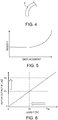
- FIG. 4 shows the third example of a shape of the rod 4 shown in FIG. 1 .
- the rods 4, each having a curved shape may be attached to the fuselage 2.
- the disk member 4A exemplified in FIG. 3 may also be attached to the tip of each rod 4 having a curved shape.
- each rod 4 having a curved shape is made of an FRP, it becomes easy to give desirable anisotropy to the mechanical characteristic.
- FIG. 5 is a graph explaining an example of a mechanical property given to the rod 4 shown in FIG. 1 .
- the horizontal axis shows displacement of the rod 4 while the vertical axis shows rigidity of the rod 4.
- a nonlinear mechanical characteristic that the rigidity of the rod 4 increases more as the displacement amount caused by bending deformation becomes larger can be given to the rod 4.
- the bending amount of the rod 4 can be made large immediately after landing of the rotorcraft 1 while the bending amount of the rod 4 can be made small gradually. Thereby, the shock at the time of landing of the rotorcraft 1 can be softened.
- Such a mechanical property can also be given to the rod 4 having a linear shape exemplified in FIG. 2 to a certain extent.
- each rod 4 when the rods 4 are attached to the fuselage 2 so that the length directions may not become parallel to the landing direction, each rod 4 can be bent in a case where the load F1, the load F2, the load F3 and the load F4 are applied on the rods 4 respectively. Thereby, the load F1, the load F2, the load F3 and the load F4 can be detected by measuring bending amounts of the rods 4 with strain gauges.
- each load sensor 5 can be composed of strain gauges or the like which detect forces and moments in three axis directions orthogonal to each other so that the bending amounts of the respective rods 4 can be measured.
- the load F1, the load F2, the load F3 and the load F4 applied on the rods 4 respectively can be calculated by known load calculations.
- the fuselage 2 or the like of the rotorcraft 1 houses a control device 6 of the rotorcraft 1, a storage 7 for storing information necessary for controlling the rotorcraft 1 and the like, an input device 8 for inputting information necessary for controlling the rotorcraft 1 and the like into the control device 6, the storage 7, or the like, and a display 9 for displaying information necessary for a flight including a taking off and landing of the rotorcraft 1.
- the input device 8 and the display 9 may be placed outside the fuselage 2 or the like so that the rotorcraft 1 can be remotely operated.
- the control device 6, the storage 7 and the input device 8 can be composed of electric circuits.
- the control device 6 can be built by reading a control program of the rotorcraft 1 into electronic circuitry, such as a computer.
- the control device 6 can control targets to be controlled, including the respective rotation numbers and the respective pitch angles of the rotors 3.
- a pitch angle is an attachment angle of blades which composes each rotor 3, and a lift by the rotor 3 can be adjusted by changing the pitch angle of the rotor 3.
- control device 6 has a function to automatically control the rotors 3 based on the load F1, the load F2, the load F3 and the load F4 applied on the rods 4 respectively, detected by the load sensors 5, at the time of a takeoff of the rotorcraft 1 so that the fuselage 2 of the rotorcraft 1 may be stabilized.
- the fuselage 2 of the rotorcraft 1 is stabilized when the load F1, the load F2, the load F3 and the load F4 applied on the rods 4 respectively are the balanced ideal loads.
- the control device 6 has a function to set targeted values of the load F1, the load F2, the load F3 and the load F4, applied on the rods 4 respectively before a takeoff of the rotorcraft 1, to desirable values which can balance the weight, and a function to control the rotation number and the pitch angle of each rotor 3 so that a state where the rotorcraft 1 does not take off while the load F1, the load F2, the load F3 and the load F4 are applied on the rods 4 respectively is made.
- the control device 6 is configured so as to automatically control outputs P1, P2, P3 and P4 of the rotors 3 so that measured values of the load F1, the load F2, the load F3 and the load F4 applied on the rods 4, detected by the load sensors 5 respectively, before the takeoff may become targeted values.
- the lifts obtained as the output P1, the output P2, the output P3 and the output P4 of the rotors 3 can be variably controlled by parameterizing the rotation numbers and the pitch angles of the rotors 3. Therefore, the control device 6 can automatically control the output P1, the output P2, the output P3 and the output P4 of the rotors 3 by automatically setting up controlling values of at least one of the rotation numbers and the pitch angles of the rotors 3.
- the control device 6 can perform feedback control which changes at least one of the rotation numbers and the pitch angles of the rotors 3 so that the measured values of the load F1, the load F2, the load F3 and the load F4 applied on the rods 4 may approximate targeted values.
- feedback control which brings the measured values of the load F1, the load F2, the load F3 and the load F4, applied on the rods 4, close to targeted values can be performed by changing at least one of the rotation number and the pitch angle of each rotor 3 by a predetermined constant increase and decrease amount.
- a change amount of at least one of the rotation number and the pitch angle of each rotor 3 can be set to an appropriate amount based on the measured values of the load F1, the load F2, the load F3 and the load F4 applied on the rods 4, a control response speed can be improved.
- information such as tables or functions, directly or indirectly expressing a relation between sets of the measured values of the load F1, the load F2, the load F3 and the load F4 applied on the rods 4 respectively before a takeoff, and sets of control values of at least one of the rotation numbers and the pitch angles of the rotors 3 for bringing the measured values of the load F1, the load F2, the load F3 and the load F4 close to targeted values
- the obtained information such as tables or functions can be stored in the storage 7.
- control device 6 becomes possible to automatically set up control values of at least one of the rotation numbers and the pitch angles of the rotors 3, corresponding to the measured values of the load F1, the load F2, the load F3 and the load F4 applied on the rods 4 respectively, with reference to the information stored in the storage 7.
- FIG. 6 is a graph showing an example of a function for automatically setting up the outputs P1, P2, P3, and P4 of the respective rotors 3 based on the loads F1, F2, F3, and F4 respectively applied on the rods 4 of the rotorcraft 1 shown in FIG. 1 .
- the horizontal axis shows a load F applied on each rod 4 of the rotorcraft 1 while the vertical axis shows an output P from each rotor 3.
- information showing a relation between measured values Fm of a load F applied on a certain rod 4 and targeted values Pt of an output P of the corresponding rotor 3, as exemplified in FIG. 6 can be stored in the storage 7 as a piece of information indirectly showing a relation between the loads F applied on the respective rods 4 before a takeoff and control values of at least one of the rotation numbers and the pitch angles of the rotors 3.
- the output P of each rotor 3 is set to an initial value Pi so that the load F applied to the corresponding rod 4 before a takeoff may be a targeted value Ft
- the measured value Fm of the load F measured by the load sensor 5 does not necessarily coincide with the targeted value Ft due to a disturbance, such as a wind.
- the targeted value Pt of the output P from each rotor 3 which should be re-set in order to bring the measured value Fm of the load F close to the targeted value Ft can be set with reference to the information, such as functions or tables.
- information for obtaining the targeted value Pt of the output P from a certain rotor 3, based on the measured value Fm of the load F applied on the corresponding rod 4, is a linear function.
- At least one value or a combination of measured values Fm of the load F1, the load F2, the load F3 and the load F4 applied on at least one of the rods 4 before a takeoff may be related to at least one value or a combination of targeted values Pt of the output P1, the output P2, the output P3 and the output P4 from at least one of the rotors 3, with at least one function or table.
- the control device 6 can specify a lift balance expressed by a combination of lifts which should be generated by the rotors 3, based on a load balance expressed by a combination of the measured values Fm of the load F1, the load F2, the load F3 and the load F4 applied to the rods 4 and detected by the load sensors 5.
- the control device 6 can automatically set up the control values of at least one of the rotation numbers and the pitch angles of the rotors 3, based on the targeted values Pt of the outputs P1, P2, P3 and P4 of the rotors 3.
- information directly showing a relation between sets of the measured values Fm of the load F1, the load F2, the load F3 and the load F4 applied on the rods 4 respectively before a takeoff and sets of the control values of at least one of the rotation numbers and the pitch angles of the rotors 3 may be prepared as functions or tables, and stored in the storage 7.
- conversion information in which the vertical axis of FIG. 6 is replaced with control values of the rotation number or the pitch angle of the rotor 3 may be previously obtained by examinations, simulations or the like, and stored as reference information in the storage 7.
- the control value of the rotation number or the pitch angle of the rotor 3 can be specified directly by referring to the reference information stored in the storage 7.
- the force acting on each rod 4 by a disturbance may change temporally. Therefore, feedback control which dynamically repeats measurement of the measured values Fm of the load F1, the load F2, the load F3 and the load F4 applied on the rods 4 respectively, and an automatic setting of the control values of the rotation numbers or the pitch angles of the rotors 3, based on the reference information stored in the storage 7 may be performed.
- the output P1, the output P2, the output P3 and the output P4 of the rotors 3 are increased under control by the control device 6 so that a lift necessary for a takeoff of the rotorcraft 1 can be generated. Thereby, the rotorcraft 1 can take off.
- control device 6 can control to stop a takeoff of the rotorcraft 1 in a case where the body of the rotorcraft 1 excessively vibrates by a disturbance, such as a wind.
- the scale of a vibration which generated on the body including the fuselage 2 of the rotorcraft 1 can be detected based on time variations of the load F1, the load F2, the load F3 and the load F4 detected by the load sensors 5.
- the vibration scale can be expressed by desired parameters, such as amplitudes and frequencies of time changes of the load F1, the load F2, the load F3 and the load F4 detected by the load sensors 5. Specifically, it can be determined that the vibration scale is large when temporal variation amounts or variation amounts per unit time of the load F1, the load F2, the load F3 and the load F4 applied on the rods 4 respectively are large.
- control device 6 can be provided with a function to detect parameters showing the vibration scale of the fuselage 2, based on time changes of the measured values Fm of the load F1, the load F2, the load F3 and the load F4 detected by the load sensors 5 and to perform processing in order to stop a takeoff when it was automatically determined that at least one detected parameter was out of an allowable range.
- Examples of processing in order to stop a takeoff of the rotorcraft 1 include control processing which automatically stops the takeoff of the rotorcraft 1 by automatically stop rotations of the rotors 3 under control by the control device 6.
- warning information to stop a takeoff may be indicated on the display 9 so that a pilot in the rotorcraft 1 or a manipulator who remotely controls the rotorcraft 1 can manually stop rotations of the rotors 3.
- Such information processing allows a judgment whether the rotorcraft 1 can take off safely, before a takeoff.
- FIG. 7 is a flow chart showing a flow of control at the time of a takeoff of the rotorcraft 1 shown in FIG. 1 .
- step S1 the control device 6 sets the targeted values Ft of the load F1, the load F2, the load F3 and the load F4 applied on the rods 4 which function as a landing gear of the rotorcraft 1.
- the targeted values Ft of the load F1, the load F2, the load F3 and the load F4 applied on the rods 4 respectively may be set as fixed values in advance, or may be variably set by operation of the input device 8.
- step S2 the values of the output P1, the output P2, the output P3 and the output P4 of the rotors 3, which should be set in order to make the load F1, the load F2, the load F3 and the load F4, applied on the rods 4 respectively, be the targeted values Ft, in a case where a force by a disturbance, such as a wind, does not act on the rotorcraft 1, are set to the initial values Pi by the control device 6.
- step S3 the control device 6 automatically controls the rotation numbers and the pitch angles of the rotors 3 so that the output P1, the output P2, the output P3 and the output P4 of the rotors 3 may be the initial values Pi. Then, a lift by which the rotorcraft 1 cannot take off is generated by rotating the rotors 3. Consequently, the load F1, the load F2, the load F3 and the load F4 applied on the rods 4 respectively decrease compared with those before starting the rotations of the rotors 3.
- step S4 the measured values Fm of the load F1, the load F2, the load F3 and the load F4 applied on the rods 4 respectively are detected by the load sensors 5.
- the detected measured values Fm of the load F1, the load F2, the load F3 and the load F4 are output from the load sensors 5 to the control device 6.
- step S5 the measured values Fm of the load F1, the load F2, the load F3 and the load F4 applied on the rods 4 respectively are compared with the targeted values Ft respectively in the control device 6. Thereby, respective deviation amounts of the measured values Fm from the targeted values Ft are obtained. For example, the differences or ratios between the targeted values Ft and the measured values Fm can be calculated as the deviation amounts of the measured values Fm respectively.
- the control device 6 automatically determines whether the deviation amounts of the measured values Fm of the load F1, the load F2, the load F3 and the load F4 applied on the rods 4 respectively are each within an allowable range.
- it is automatically determined by threshold processing whether the measured values Fm of the load F1, the load F2, the load F3 and the load F4 applied on the rods 4 respectively are each within an allowable range which is specified by an upper limit value and a lower limit value, such as ⁇ 10 [N], set experientially.
- the measured value Fm of the load F applied on a certain rod 4 exceeds an allowable range and becomes excessive as exemplified in FIG. 6 .
- the control value of the output P of at least one corresponding rotor 3 is corrected to the targeted value Pt, in step S6.
- the targeted value Pt of the output P of the at least one corresponding rotor 3 can be automatically set in the control device 6, based on the reference information expressed as a function or a table as exemplified in FIG. 6 .
- control device 6 refers to the reference information, such as a linear function, stored in the storage 7 and automatically set the targeted values Pt of the output P1, the output P2, the output P3 and the output P4 of the rotors 3, corresponding to the measured values Fm of the load F1, the load F2, the load F3 and the load F4 applied on the rods 4 respectively.
- reference information such as a linear function
- step S7 the control device 6 automatically controls the rotation numbers and the pitch angles of the rotors so that the output P1, the output P2, the output P3 and the output P4 of the rotors 3 may be the targeted values Pt.
- the measured values Fm of the load F1, the load F2, the load F3 and the load F4 applied on the rods 4 respectively can be brought close to the targeted values Ft. That is, the rotors 3 can be automatically controlled so that the body including the fuselage 2 can be stabilized.
- step S4 After at least one of the rotation number and the pitch angle of at least one rotor 3 has been changed, the measurement of the measured values Fm of the load F1, the load F2, the load F3 and the load F4 in step S4 and the determination in step S5 are performed again.
- step S6 the correction of the targeted value Pt or the targeted values Pt of the output P1, the output P2, the output P3 and/or the output P4 of a rotor 3 or rotors 3 in step S6 and the control of the rotation number and the pitch angle of each rotor 3 in step S7 are repeated until it is determined that all of the deviation amounts from the targeted values Ft, of the measured values Fm of the load F1, the load F2, the load F3 and the load F4 applied on the rods 4 are each within an allowable range in the determination in step S5.
- the measured values Fm of the load F1, the load F2, the load F3 and the load F4 applied on the rods 4 can be brought close to the targeted values Ft respectively.
- step S5 takeoff control of the rotorcraft 1 is performed in step S8. That is, the control device 6 increases the output P1, the output P2, the output P3 and the output P4 of the rotors 3.
- the measured values Fm of the load F1, the load F2, the load F3 and the load F4 applied on the rods 4 decrease gradually, and the rotorcraft 1 takes off at the time when each of the measured values Fm of the load F1, the load F2, the load F3 and the load F4 becomes zero.
- the vibration scale of the rotorcraft 1 may be detected based on time changes of the load F1, the load F2, the load F3 and the load F4 detected by the load sensors 5 in advance of the flow shown in FIG. 7 , and a takeoff can be stopped when a vibration has become excessive.
- the load sensors 5 attached to the rods 4 which are landing devices of the rotorcraft 1 measures the measured values Fm of the loads F, and the outputs P of the necessary rotors 3 out of the rotors 3 are corrected so that the rotorcraft 1 takes off after the load F applied to each rod 4 has become the targeted value Ft.
- the instability of the body at the time of a takeoff can be suppressed.
- stability and safety can be improved.
- the attitude of the body of the rotorcraft 1 can be stabilized since the rotorcraft 1 can take off after uniforming the load F1, the load F2, the load F3 and the load F4 applied on the rods 4, composing a landing gear, just before a takeoff of the rotorcraft 1.
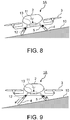
- FIG. 8 is a front view showing structure of a rotorcraft according to the second embodiment of the present invention.
- a rotorcraft 1A in the second embodiment shown in FIG. 8 is different from the rotorcraft 1 in the first embodiment in a structure by which the attitude of the body can be horizontal even when the rotorcraft 1A lands on a sloping surface 10.
- Other configurations and actions of the rotorcraft 1A in the second embodiment are not substantially different from those of the rotorcraft 1 in the first embodiment. Therefore, only a schematic front view of the rotorcraft 1A is shown, and the same signs are attached to the same elements or the corresponding elements while explanation thereof is omitted.
- the rotorcraft 1A in the second embodiment includes an angle sensor 11, expansion mechanisms 12 and a rod control device 13 in addition to elements similar to those in the first embodiment.
- the angle sensor 11 detects an inclined angle of the body including the fuselage 2, relative to the horizontal direction.
- the expansion mechanisms 12 expand and contract the rods 4 respectively.
- the rod control device 13 expands and contracts the rods 4 by controlling the expansion mechanisms 12 respectively.
- the angle sensor 11 can be disposed at a desired position as long as a spatial inclined angle of the body can be measured.
- Examples of the expansion mechanism 12 which expands and contracts the rod 4 include known mechanisms, such as a rack and pinion which is a kind of gears, a ball screw and a cylinder mechanism having a piston.
- the rod control device 13 can be composed of electronic circuitry, such as a computer, which has read a program, similarly to the control device 6 of the rotorcraft 1A. Accordingly, the rod control device 13 may be integrated with the control device 6 of the rotorcraft 1A.
- the attitude may become unstable since a lift generated by each rotor 3 is not in the vertical direction. Accordingly, the inclination of the rotorcraft 1A can be detected by the angle sensor 11, and the attitude of the rotorcraft 1A can be horizontal by expanding and contracting the necessary rods 4 by the expansion mechanisms 12 when the rotorcraft 1A is inclined.
- the inclined angle to the horizontal direction of the rotorcraft 1A detected by the angle sensor 11 can be output to the rod control device 13. Then, the rod control device 13 can determine whether the inclined angle of the rotorcraft 1A is within an allowable range, by threshold processing.
- the rod control device 13 can control the expansion mechanisms 12 to expand and contract at least one of the rods 4 so that the inclined angle of the rotorcraft 1A detected by the angle sensor 11 may become within the allowable range.
- FIG. 9 is a front view showing a state where the attitude of the rotorcraft 1A shown in FIG. 8 is horizontal.
- the rods 4 can be expanded and contracted according to an inclined angle of the sloping surface 10.
- the body of the rotorcraft 1A can be made horizontal and a lift obtained by rotation of each rotor 3 can be directed in the vertical direction.
- stabilization control including setting the targeted values Ft of the load F1, the load F2, the load F3 and the load F4 applied to the rods 4 and setting the targeted values Pt of the output P1, the output P2, the output P3 and the output P4 of the rotors 3, similarly to the first embodiment.
- the protruding length of the rod 4 or the length itself of the rod 4 is changed depending on a structure of the rod 4.
- the tip of the rod 4 may be bent and deformed with a different deformation amount even when the load F applied on the rod 4 is constant.
- each load sensor 5 can be configured to detect the load F applied on the rod 4, based on an expansion amount and a deformation amount of the rod 4.
- a stable takeoff can be realized by avoiding generation of a lift in a direction oblique to the vertical direction even when the rotorcraft 1A takes off from the sloping surface 10 oblique to the horizontal direction.
Landscapes
- Engineering & Computer Science (AREA)
- Aviation & Aerospace Engineering (AREA)
- Remote Sensing (AREA)
- Mechanical Engineering (AREA)
- General Physics & Mathematics (AREA)
- Radar, Positioning & Navigation (AREA)
- Physics & Mathematics (AREA)
- Automation & Control Theory (AREA)
- Composite Materials (AREA)
- Materials Engineering (AREA)
- Chemical & Material Sciences (AREA)
- Testing Of Devices, Machine Parts, Or Other Structures Thereof (AREA)
- Toys (AREA)
Abstract
Description
- Embodiments described herein relate generally to a rotorcraft and a method of controlling a rotorcraft.
- Conventionally, a rotorcraft having a plurality of rotors is known. In particular, a rotorcraft having not less than three rotors is also called a multi-copter. Conventionally, attitude control of a rotorcraft mounting rotors is performed by detecting the attitude of the rotorcraft using a gyroscope sensor or the like (for example, refer to Japanese Patent Application Publication
JP 2006-051841 A - Moreover, in order to stabilize a flight of a multi-copter or the like which carries freight, a technique of calculating and displaying a barycentric position by load sensors has also been proposed (for example, refer to Japanese Patent Application Publication
JP 2017-159873 A JP H11-310199 A - However, in the method of controlling an attitude by detecting the attitude by a gyroscope sensor or the like, control command signals for changing thrust are output to rotors after the attitude changed. Therefore, control directions and responses of an attitude are delayed, which causes instability of the attitude at the time of a takeoff of a rotorcraft. When an attitude of a rotorcraft becomes unstable, the risk of falling increases.
- Accordingly, an object of the present invention is to improve the safety at the time of a takeoff of a rotorcraft having rotors.
- In general, according to one embodiment, a rotorcraft includes rotors, a fuselage, at least three rods, at least one load sensor and a control device. The rotors obtain lift. The fuselage is coupled to the rotors. The at least three rods support the fuselage. The at least one load sensor detects loads applied on the at least three rods. The control device automatically controls the rotors so that measured values of the loads detected by the at least one load sensor are brought to targeted values of the loads.
- Further, according to one embodiment, a method of controlling a rotorcraft, having rotors for obtaining lift, a fuselage coupled to the rotors, and at least three rods that support the fuselage, includes: detecting loads applied on the at least three rods; and automatically controlling the rotors so that measured values of the detected loads are brought to targeted values of the loads.
- In the accompanying drawings:
- FIG. 1
- is a perspective view showing structure of a rotorcraft according to the first embodiment of the present invention;
- FIG. 2
- shows a first example of a shape of the rod shown in
FIG. 1 ; - FIG. 3
- shows a second example of a shape of the rod shown in
FIG. 1 ; - FIG. 4
- shows a third example of a shape of the rod shown in
FIG. 1 ; - FIG. 5
- is a graph explaining an example of a mechanical property given to the rod shown in
FIG. 1 ; - FIG. 6
- is a graph showing an example of a function for automatically setting up the outputs of the respective rotors based on the loads respectively applied on the rods of the rotorcraft shown in
FIG. 1 ; - FIG. 7
- is a flow chart showing a flow of control at the time of a takeoff of the rotorcraft shown in
FIG. 1 ; - FIG. 8
- is a front view showing structure of a rotorcraft according to the second embodiment of the present invention; and
- FIG. 9
- is a front view showing a state where the attitude of the rotorcraft shown in
FIG. 8 is horizontal. - A rotorcraft and a method of controlling a rotorcraft according to embodiments of the present invention will be described with reference to the accompanying drawings.
-
FIG. 1 is a perspective view showing structure of a rotorcraft according to the first embodiment of the present invention. - A
rotorcraft 1 is composed of afuselage 2,rotors 3 androds 4. Therotors 3 and therods 4 are attached to thefuselage 2. Therotorcraft 1 having not less than threerotors 3 is called a multicopter. As a matter of course, therotorcraft 1 may be a helicopter which has tworotors 3. - The
rotorcraft 1 may be not only a UAV (Unmanned aerial vehicle) on which people do not board but also an OPV (Optionally Piloted Vehicle) on which people board. An OPV is an unmanned aerial vehicle which a pilot can also board and drive, i.e., a hybrid aircraft of a manned aircraft and an unmanned aircraft. A UAV is also called a drone and typical UAVs include an unmanned multicopter and helicopter. - The
rotors 3 are rotary wings for obtaining lifts at different positions. Eachrotor 3 may has a tilt function so that thrust can be obtained by tilting eachrotor 3 after a takeoff of therotorcraft 1. In addition, a rotor having a purpose other than the purpose of obtaining a lift, such as a tail rotor, may be coupled to thefuselage 2 besides therotors 3 for obtaining lifts. - The
rods 4 are landing gears, which support thefuselage 2, by respectively contacting their tips to a surface on which therotorcraft 1 lands while therotorcraft 1 has landed. That is, therotorcraft 1 does not necessarily have wheels and can land with the tips of therods 4 as exemplified inFIG. 1 . As a matter of course, wheels may be attached to the tips of therods 4 for landing with the wheels, regardless of an example shown inFIG. 1 . - Henceforth, an example of a case where the
rotorcraft 1 lands with the tips of therods 4 as exemplified inFIG. 1 will be mainly described. It is necessary to couple at least threerods 4 to thefuselage 2 in order to land on the ground or the like, and support thefuselage 2. In the illustrated example, fourrods 4 have been attached to the lower part of thefuselage 2. - A
load sensor 5 is attached to eachrod 4. Therefore, a load F1, a load F2, a load F3 and a load F4 applied on therespective rods 4 due to the weight of therotorcraft 1 except therods 4 their selves can be detected by theload sensors 5 respectively before a takeoff of therotorcraft 1. Eachload sensor 5 can be composed of at least one known sensor, such as a strain gauge or a piezo element. Therefore, an attachment position of theload sensor 5 to eachrod 4 is determined to an appropriate position, such as a middle portion or a root portion of eachrod 4, according to a shape of eachrod 4 and a kind of theload sensor 5. -
FIG. 2 shows the first example of a shape of therod 4 shown inFIG. 1 . - As exemplified in
FIG. 2 , therods 4, each having a linear shape without curvature, can be attached to thefuselage 2 so as to open outward. When a shape of eachrod 4 is linear, design and production of eachrod 4 become easy. The material of eachrod 4 is flexible and may be a metal or a composite material as long as the metal has the strength which can support a load of therotorcraft 1. When a metal is used as a material of eachrod 4, for example, material cost can be reduced. Meanwhile, when a composite material is used as a material of eachrod 4, weight saving can be attained with keeping high strength. - A composite material is also called an FRP (Fiber reinforced plastic), and a GFRP (Glass fiber reinforced plastic) and a CFRP (Carbon fiber reinforced plastics) are typical.
-
FIG. 3 shows the second example of a shape of therod 4 shown inFIG. 1 . - As exemplified in
FIG. 3 , adisk member 4A may be attached to the tip of eachrod 4. When thedisk member 4A is attached to the tip of eachrod 4, therotorcraft 1 becomes possible to land on a place of which surface is not rigid, such as a place on the water, marshes, a liquefied land or a place covered with plant. -
FIG. 4 shows the third example of a shape of therod 4 shown inFIG. 1 . - As exemplified in
FIG. 4 , therods 4, each having a curved shape, may be attached to thefuselage 2. As a matter of course, thedisk member 4A exemplified inFIG. 3 may also be attached to the tip of eachrod 4 having a curved shape. In particular, when eachrod 4 having a curved shape is made of an FRP, it becomes easy to give desirable anisotropy to the mechanical characteristic. -
FIG. 5 is a graph explaining an example of a mechanical property given to therod 4 shown inFIG. 1 . - In
FIG. 5 , the horizontal axis shows displacement of therod 4 while the vertical axis shows rigidity of therod 4. As exemplified inFIG. 5 , a nonlinear mechanical characteristic that the rigidity of therod 4 increases more as the displacement amount caused by bending deformation becomes larger can be given to therod 4. - Then, the bending amount of the
rod 4 can be made large immediately after landing of therotorcraft 1 while the bending amount of therod 4 can be made small gradually. Thereby, the shock at the time of landing of therotorcraft 1 can be softened. Such a mechanical property can also be given to therod 4 having a linear shape exemplified inFIG. 2 to a certain extent. - In addition, when the
rods 4 as exemplified inFIG. 2 orFIG. 4 are attached to thefuselage 2 so that the length directions may not become the same direction, the shock to eachrod 4 at the time of landing of therotorcraft 1 can be eased and failure of theload sensors 5 can be prevented, regardless of whether the mechanical property exemplified byFIG. 5 is given to eachrod 4 or not. - In particular, when the
rods 4 are attached to thefuselage 2 so that the length directions may not become parallel to the landing direction, eachrod 4 can be bent in a case where the load F1, the load F2, the load F3 and the load F4 are applied on therods 4 respectively. Thereby, the load F1, the load F2, the load F3 and the load F4 can be detected by measuring bending amounts of therods 4 with strain gauges. - Specifically, each
load sensor 5 can be composed of strain gauges or the like which detect forces and moments in three axis directions orthogonal to each other so that the bending amounts of therespective rods 4 can be measured. Thereby, the load F1, the load F2, the load F3 and the load F4 applied on therods 4 respectively can be calculated by known load calculations. - The
fuselage 2 or the like of therotorcraft 1 houses acontrol device 6 of therotorcraft 1, astorage 7 for storing information necessary for controlling therotorcraft 1 and the like, aninput device 8 for inputting information necessary for controlling therotorcraft 1 and the like into thecontrol device 6, thestorage 7, or the like, and adisplay 9 for displaying information necessary for a flight including a taking off and landing of therotorcraft 1. Note that, theinput device 8 and thedisplay 9 may be placed outside thefuselage 2 or the like so that therotorcraft 1 can be remotely operated. - The
control device 6, thestorage 7 and theinput device 8 can be composed of electric circuits. Thecontrol device 6 can be built by reading a control program of therotorcraft 1 into electronic circuitry, such as a computer. - The
control device 6 can control targets to be controlled, including the respective rotation numbers and the respective pitch angles of therotors 3. A pitch angle is an attachment angle of blades which composes eachrotor 3, and a lift by therotor 3 can be adjusted by changing the pitch angle of therotor 3. - In particular, the
control device 6 has a function to automatically control therotors 3 based on the load F1, the load F2, the load F3 and the load F4 applied on therods 4 respectively, detected by theload sensors 5, at the time of a takeoff of therotorcraft 1 so that thefuselage 2 of therotorcraft 1 may be stabilized. Thefuselage 2 of therotorcraft 1 is stabilized when the load F1, the load F2, the load F3 and the load F4 applied on therods 4 respectively are the balanced ideal loads. - When any force acting on the
rotorcraft 1 other than the gravity is negligible, the ideal load F1, load F2, load F3 and load F4, corresponding to the weight of therotorcraft 1, which have been defined at the time of designing therotorcraft 1, are applied on therods 4 respectively. Therefore, the attitude of therotorcraft 1 is stabilized. - Meanwhile, when a force other than the gravity acting on the body of the
rotorcraft 1 acts on therotorcraft 1 by a disturbance, such as a wind or a cargo with large weight, the load F1, the load F2, the load F3 and the load F4 applied on therods 4 respectively are changed. When therotorcraft 1 takes off in an imbalanced state where the load F1, the load F2, the load F3 and the load F4 applied on therods 4 respectively have been changed, the attitude of therotorcraft 1 becomes unstable. When the attitude of therotorcraft 1 becomes unstable, the risk of fall increases. - Thus, the
control device 6 has a function to set targeted values of the load F1, the load F2, the load F3 and the load F4, applied on therods 4 respectively before a takeoff of therotorcraft 1, to desirable values which can balance the weight, and a function to control the rotation number and the pitch angle of eachrotor 3 so that a state where therotorcraft 1 does not take off while the load F1, the load F2, the load F3 and the load F4 are applied on therods 4 respectively is made. - Thereby, the load F1, the load F2, the load F3 and the load F4 applied on the
rods 4 respectively in a state where the attitude of therotorcraft 1 does not change before a takeoff of therotorcraft 1 can be detected by theload sensors 5 respectively. Then, thecontrol device 6 is configured so as to automatically control outputs P1, P2, P3 and P4 of therotors 3 so that measured values of the load F1, the load F2, the load F3 and the load F4 applied on therods 4, detected by theload sensors 5 respectively, before the takeoff may become targeted values. - The lifts obtained as the output P1, the output P2, the output P3 and the output P4 of the
rotors 3 can be variably controlled by parameterizing the rotation numbers and the pitch angles of therotors 3. Therefore, thecontrol device 6 can automatically control the output P1, the output P2, the output P3 and the output P4 of therotors 3 by automatically setting up controlling values of at least one of the rotation numbers and the pitch angles of therotors 3. - Since a disturbance, such as a wind, may temporally change, the output P1, the output P2, the output P3 and the output P4 of the
rotors 3, which should be obtained in order to bring the measured values of the load F1, the load F2, the load F3 and the load F4, applied on therods 4 respectively, close to targeted values, may also temporally change. Therefore, thecontrol device 6 can perform feedback control which changes at least one of the rotation numbers and the pitch angles of therotors 3 so that the measured values of the load F1, the load F2, the load F3 and the load F4 applied on therods 4 may approximate targeted values. - As a specific example, feedback control which brings the measured values of the load F1, the load F2, the load F3 and the load F4, applied on the
rods 4, close to targeted values can be performed by changing at least one of the rotation number and the pitch angle of eachrotor 3 by a predetermined constant increase and decrease amount. When a change amount of at least one of the rotation number and the pitch angle of eachrotor 3 can be set to an appropriate amount based on the measured values of the load F1, the load F2, the load F3 and the load F4 applied on therods 4, a control response speed can be improved. - Accordingly, information, such as tables or functions, directly or indirectly expressing a relation between sets of the measured values of the load F1, the load F2, the load F3 and the load F4 applied on the
rods 4 respectively before a takeoff, and sets of control values of at least one of the rotation numbers and the pitch angles of therotors 3 for bringing the measured values of the load F1, the load F2, the load F3 and the load F4 close to targeted values can be obtained beforehand by examinations or simulations. Then, the obtained information, such as tables or functions can be stored in thestorage 7. - Thereby, the
control device 6 becomes possible to automatically set up control values of at least one of the rotation numbers and the pitch angles of therotors 3, corresponding to the measured values of the load F1, the load F2, the load F3 and the load F4 applied on therods 4 respectively, with reference to the information stored in thestorage 7. - That is, it becomes possible to change control values of the rotation numbers and the pitch angles of the
rotors 3 to appropriate control values according to the measured values of the load F1, the load F2, the load F3 and the load F4 applied on therods 4 respectively, instead of gradually changing the control values of the rotation numbers and the pitch angles of therotors 3. -
FIG. 6 is a graph showing an example of a function for automatically setting up the outputs P1, P2, P3, and P4 of therespective rotors 3 based on the loads F1, F2, F3, and F4 respectively applied on therods 4 of therotorcraft 1 shown inFIG. 1 . - In
FIG. 6 , the horizontal axis shows a load F applied on eachrod 4 of therotorcraft 1 while the vertical axis shows an output P from eachrotor 3. For example, information showing a relation between measured values Fm of a load F applied on acertain rod 4 and targeted values Pt of an output P of thecorresponding rotor 3, as exemplified inFIG. 6 , can be stored in thestorage 7 as a piece of information indirectly showing a relation between the loads F applied on therespective rods 4 before a takeoff and control values of at least one of the rotation numbers and the pitch angles of therotors 3. - Specifically, even when the output P of each
rotor 3 is set to an initial value Pi so that the load F applied to thecorresponding rod 4 before a takeoff may be a targeted value Ft, the measured value Fm of the load F measured by theload sensor 5 does not necessarily coincide with the targeted value Ft due to a disturbance, such as a wind. In such a case, the targeted value Pt of the output P from eachrotor 3 which should be re-set in order to bring the measured value Fm of the load F close to the targeted value Ft can be set with reference to the information, such as functions or tables. In the example shown inFIG. 6 , information for obtaining the targeted value Pt of the output P from acertain rotor 3, based on the measured value Fm of the load F applied on thecorresponding rod 4, is a linear function. - Although a function has been prepared so that the targeted value Pt of the output P from a
certain rotor 3 can be obtained based on the measured value Fm of the load F applied on the corresponding onerod 4 in the example shown inFIG. 6 , it may be appropriate or unavoidable to adjust the load F applied on one of therods 4 or the loads F applied on the plurality of therods 4 by changing the output P from one of therotors 3 or the outputs P from the plurality of therotors 3, like when the number of therods 4 is different from the number of therotors 3 or when positions of therods 4 do not correspond to positions of therotors 3. - Accordingly, at least one value or a combination of measured values Fm of the load F1, the load F2, the load F3 and the load F4 applied on at least one of the
rods 4 before a takeoff may be related to at least one value or a combination of targeted values Pt of the output P1, the output P2, the output P3 and the output P4 from at least one of therotors 3, with at least one function or table. - When such a function as a database for converting the measured value Fm or the measured values Fm of the load F1, the load F2, the load F3 and the load F4, applied on at least one of the
rods 4, into the targeted value Pt or the targeted values Pt of the output P1, the output P2, the output P3 and the output P4 of at least one of therotors 3 is prepared in thestorage 7, thecontrol device 6 can specify a lift balance expressed by a combination of lifts which should be generated by therotors 3, based on a load balance expressed by a combination of the measured values Fm of the load F1, the load F2, the load F3 and the load F4 applied to therods 4 and detected by theload sensors 5. - When the targeted values Pt of the outputs P1, P2, P3 and P4 from the
rotors 3 have been automatically set up in thecontrol device 6, thecontrol device 6 can automatically set up the control values of at least one of the rotation numbers and the pitch angles of therotors 3, based on the targeted values Pt of the outputs P1, P2, P3 and P4 of therotors 3. - Note that, information directly showing a relation between sets of the measured values Fm of the load F1, the load F2, the load F3 and the load F4 applied on the
rods 4 respectively before a takeoff and sets of the control values of at least one of the rotation numbers and the pitch angles of therotors 3 may be prepared as functions or tables, and stored in thestorage 7. - That is, conversion information in which the vertical axis of
FIG. 6 is replaced with control values of the rotation number or the pitch angle of therotor 3 may be previously obtained by examinations, simulations or the like, and stored as reference information in thestorage 7. In that case, the control value of the rotation number or the pitch angle of therotor 3 can be specified directly by referring to the reference information stored in thestorage 7. - As mentioned above, the force acting on each
rod 4 by a disturbance may change temporally. Therefore, feedback control which dynamically repeats measurement of the measured values Fm of the load F1, the load F2, the load F3 and the load F4 applied on therods 4 respectively, and an automatic setting of the control values of the rotation numbers or the pitch angles of therotors 3, based on the reference information stored in thestorage 7 may be performed. - Conversely, when the force acting on each
rod 4 by a disturbance does not change temporally, one correction to the control values of at least one of the rotation numbers and the pitch angles of therotors 3, based on the reference information makes the load F1, the load F2, the load F3 and the load F4 applied on therods 4 respectively become the targeted values Ft theoretically. - Then, after the load F1, the load F2, the load F3 and the load F4 applied on the
rods 4 respectively have reached the targeted values Ft, the output P1, the output P2, the output P3 and the output P4 of therotors 3 are increased under control by thecontrol device 6 so that a lift necessary for a takeoff of therotorcraft 1 can be generated. Thereby, therotorcraft 1 can take off. - In addition to such automatic control of the
rotors 3 for the stabilization at the time of a takeoff of therotorcraft 1, thecontrol device 6 can control to stop a takeoff of therotorcraft 1 in a case where the body of therotorcraft 1 excessively vibrates by a disturbance, such as a wind. The scale of a vibration which generated on the body including thefuselage 2 of therotorcraft 1 can be detected based on time variations of the load F1, the load F2, the load F3 and the load F4 detected by theload sensors 5. - The vibration scale can be expressed by desired parameters, such as amplitudes and frequencies of time changes of the load F1, the load F2, the load F3 and the load F4 detected by the
load sensors 5. Specifically, it can be determined that the vibration scale is large when temporal variation amounts or variation amounts per unit time of the load F1, the load F2, the load F3 and the load F4 applied on therods 4 respectively are large. - Therefore, it can be detected whether vibration is so excessive that a takeoff of the
rotorcraft 1 should be stopped, by threshold processing of each parameter showing the vibration scale of the body including thefuselage 2, which determines whether each parameter showing the vibration scale of the body including thefuselage 2 is within an allowable range. - Accordingly, the
control device 6 can be provided with a function to detect parameters showing the vibration scale of thefuselage 2, based on time changes of the measured values Fm of the load F1, the load F2, the load F3 and the load F4 detected by theload sensors 5 and to perform processing in order to stop a takeoff when it was automatically determined that at least one detected parameter was out of an allowable range. - Examples of processing in order to stop a takeoff of the
rotorcraft 1 include control processing which automatically stops the takeoff of therotorcraft 1 by automatically stop rotations of therotors 3 under control by thecontrol device 6. - Alternatively, warning information to stop a takeoff may be indicated on the
display 9 so that a pilot in therotorcraft 1 or a manipulator who remotely controls therotorcraft 1 can manually stop rotations of therotors 3. Such information processing allows a judgment whether therotorcraft 1 can take off safely, before a takeoff. - Next, a method of controlling the
rotorcraft 1 will be described. -
FIG. 7 is a flow chart showing a flow of control at the time of a takeoff of therotorcraft 1 shown inFIG. 1 . - Firstly, in step S1, the
control device 6 sets the targeted values Ft of the load F1, the load F2, the load F3 and the load F4 applied on therods 4 which function as a landing gear of therotorcraft 1. The targeted values Ft of the load F1, the load F2, the load F3 and the load F4 applied on therods 4 respectively may be set as fixed values in advance, or may be variably set by operation of theinput device 8. - Next, in step S2, the values of the output P1, the output P2, the output P3 and the output P4 of the
rotors 3, which should be set in order to make the load F1, the load F2, the load F3 and the load F4, applied on therods 4 respectively, be the targeted values Ft, in a case where a force by a disturbance, such as a wind, does not act on therotorcraft 1, are set to the initial values Pi by thecontrol device 6. - Next, in step S3, the
control device 6 automatically controls the rotation numbers and the pitch angles of therotors 3 so that the output P1, the output P2, the output P3 and the output P4 of therotors 3 may be the initial values Pi. Then, a lift by which therotorcraft 1 cannot take off is generated by rotating therotors 3. Consequently, the load F1, the load F2, the load F3 and the load F4 applied on therods 4 respectively decrease compared with those before starting the rotations of therotors 3. - Next, in step S4, the measured values Fm of the load F1, the load F2, the load F3 and the load F4 applied on the
rods 4 respectively are detected by theload sensors 5. The detected measured values Fm of the load F1, the load F2, the load F3 and the load F4 are output from theload sensors 5 to thecontrol device 6. - Next, in step S5, the measured values Fm of the load F1, the load F2, the load F3 and the load F4 applied on the
rods 4 respectively are compared with the targeted values Ft respectively in thecontrol device 6. Thereby, respective deviation amounts of the measured values Fm from the targeted values Ft are obtained. For example, the differences or ratios between the targeted values Ft and the measured values Fm can be calculated as the deviation amounts of the measured values Fm respectively. - Then, the
control device 6 automatically determines whether the deviation amounts of the measured values Fm of the load F1, the load F2, the load F3 and the load F4 applied on therods 4 respectively are each within an allowable range. As a concrete example, it is automatically determined by threshold processing whether the measured values Fm of the load F1, the load F2, the load F3 and the load F4 applied on therods 4 respectively are each within an allowable range which is specified by an upper limit value and a lower limit value, such as ±10 [N], set experientially. - When at least one of the load F1, the load F2, the load F3 and the load F4 applied on the
rods 4 respectively increases by a force, such as a wind force or the gravity acting on cargos, other than the gravity acting on therotorcraft 1 itself, at least one of the measured values Fm of the load F1, the load F2, the load F3 and the load F4 applied on therods 4 respectively may be out of an allowable range. For example, the measured value Fm of the load F applied on acertain rod 4 exceeds an allowable range and becomes excessive as exemplified inFIG. 6 . - In such a case, the control value of the output P of at least one corresponding
rotor 3 is corrected to the targeted value Pt, in step S6. The targeted value Pt of the output P of the at least one correspondingrotor 3 can be automatically set in thecontrol device 6, based on the reference information expressed as a function or a table as exemplified inFIG. 6 . - Specifically, the
control device 6 refers to the reference information, such as a linear function, stored in thestorage 7 and automatically set the targeted values Pt of the output P1, the output P2, the output P3 and the output P4 of therotors 3, corresponding to the measured values Fm of the load F1, the load F2, the load F3 and the load F4 applied on therods 4 respectively. - Next, in step S7, the
control device 6 automatically controls the rotation numbers and the pitch angles of the rotors so that the output P1, the output P2, the output P3 and the output P4 of therotors 3 may be the targeted values Pt. Thereby, the measured values Fm of the load F1, the load F2, the load F3 and the load F4 applied on therods 4 respectively can be brought close to the targeted values Ft. That is, therotors 3 can be automatically controlled so that the body including thefuselage 2 can be stabilized. - After at least one of the rotation number and the pitch angle of at least one
rotor 3 has been changed, the measurement of the measured values Fm of the load F1, the load F2, the load F3 and the load F4 in step S4 and the determination in step S5 are performed again. Then, the correction of the targeted value Pt or the targeted values Pt of the output P1, the output P2, the output P3 and/or the output P4 of arotor 3 orrotors 3 in step S6 and the control of the rotation number and the pitch angle of eachrotor 3 in step S7 are repeated until it is determined that all of the deviation amounts from the targeted values Ft, of the measured values Fm of the load F1, the load F2, the load F3 and the load F4 applied on therods 4 are each within an allowable range in the determination in step S5. - That is, feedback control which resets the targeted values Pt of the output P1, the output P2, the output P3 and the output P4 of the
rotors 3 in order to bring the measured values Fm of the load F1, the load F2, the load F3 and the load F4, applied on therods 4 respectively, close to the targeted values Ft is performed. - Thereby, even when the magnitude of a force by a disturbance, such as a wind, temporally changes, the measured values Fm of the load F1, the load F2, the load F3 and the load F4 applied on the
rods 4 can be brought close to the targeted values Ft respectively. - When it has been determined that all of the deviation amounts from the targeted values Ft, of the measured values Fm of the load F1, the load F2, the load F3 and the load F4 applied on the
rods 4 are each within an allowable range, in the determination in step S5, takeoff control of therotorcraft 1 is performed in step S8. That is, thecontrol device 6 increases the output P1, the output P2, the output P3 and the output P4 of therotors 3. - Thereby, the measured values Fm of the load F1, the load F2, the load F3 and the load F4 applied on the
rods 4 decrease gradually, and therotorcraft 1 takes off at the time when each of the measured values Fm of the load F1, the load F2, the load F3 and the load F4 becomes zero. - Note that, the vibration scale of the
rotorcraft 1 may be detected based on time changes of the load F1, the load F2, the load F3 and the load F4 detected by theload sensors 5 in advance of the flow shown inFIG. 7 , and a takeoff can be stopped when a vibration has become excessive. - As described above, in the
rotorcraft 1 and the method of controlling therotorcraft 1, theload sensors 5 attached to therods 4 which are landing devices of therotorcraft 1 measures the measured values Fm of the loads F, and the outputs P of thenecessary rotors 3 out of therotors 3 are corrected so that therotorcraft 1 takes off after the load F applied to eachrod 4 has become the targeted value Ft. - Therefore, according to the
rotorcraft 1 and the method of controlling therotorcraft 1, the instability of the body at the time of a takeoff can be suppressed. Thereby, stability and safety can be improved. Specifically, the attitude of the body of therotorcraft 1 can be stabilized since therotorcraft 1 can take off after uniforming the load F1, the load F2, the load F3 and the load F4 applied on therods 4, composing a landing gear, just before a takeoff of therotorcraft 1. - Moreover, when a vibration of the
rotorcraft 1 is excessively large, a takeoff can be canceled and safety can also be secured. -
FIG. 8 is a front view showing structure of a rotorcraft according to the second embodiment of the present invention. - A
rotorcraft 1A in the second embodiment shown inFIG. 8 is different from therotorcraft 1 in the first embodiment in a structure by which the attitude of the body can be horizontal even when therotorcraft 1A lands on a slopingsurface 10. Other configurations and actions of therotorcraft 1A in the second embodiment are not substantially different from those of therotorcraft 1 in the first embodiment. Therefore, only a schematic front view of therotorcraft 1A is shown, and the same signs are attached to the same elements or the corresponding elements while explanation thereof is omitted. - The
rotorcraft 1A in the second embodiment includes anangle sensor 11,expansion mechanisms 12 and arod control device 13 in addition to elements similar to those in the first embodiment. Theangle sensor 11 detects an inclined angle of the body including thefuselage 2, relative to the horizontal direction. Theexpansion mechanisms 12 expand and contract therods 4 respectively. Therod control device 13 expands and contracts therods 4 by controlling theexpansion mechanisms 12 respectively. - The
angle sensor 11 can be disposed at a desired position as long as a spatial inclined angle of the body can be measured. Examples of theexpansion mechanism 12 which expands and contracts therod 4 include known mechanisms, such as a rack and pinion which is a kind of gears, a ball screw and a cylinder mechanism having a piston. - The
rod control device 13 can be composed of electronic circuitry, such as a computer, which has read a program, similarly to thecontrol device 6 of therotorcraft 1A. Accordingly, therod control device 13 may be integrated with thecontrol device 6 of therotorcraft 1A. - When the
rotorcraft 1A attempts to take off from the slopingsurface 10 which slants to the horizontal direction as exemplified inFIG. 8 , the attitude may become unstable since a lift generated by eachrotor 3 is not in the vertical direction. Accordingly, the inclination of therotorcraft 1A can be detected by theangle sensor 11, and the attitude of therotorcraft 1A can be horizontal by expanding and contracting thenecessary rods 4 by theexpansion mechanisms 12 when therotorcraft 1A is inclined. - More specifically, the inclined angle to the horizontal direction of the
rotorcraft 1A detected by theangle sensor 11 can be output to therod control device 13. Then, therod control device 13 can determine whether the inclined angle of therotorcraft 1A is within an allowable range, by threshold processing. - When it has been determined that the inclined angle of the
rotorcraft 1A was out of the allowable range, therod control device 13 can control theexpansion mechanisms 12 to expand and contract at least one of therods 4 so that the inclined angle of therotorcraft 1A detected by theangle sensor 11 may become within the allowable range. -
FIG. 9 is a front view showing a state where the attitude of therotorcraft 1A shown inFIG. 8 is horizontal. - As shown in
FIG. 9 , therods 4 can be expanded and contracted according to an inclined angle of the slopingsurface 10. Thereby, the body of therotorcraft 1A can be made horizontal and a lift obtained by rotation of eachrotor 3 can be directed in the vertical direction. As a result, it becomes possible to perform stabilization control at the time of a takeoff, including setting the targeted values Ft of the load F1, the load F2, the load F3 and the load F4 applied to therods 4 and setting the targeted values Pt of the output P1, the output P2, the output P3 and the output P4 of therotors 3, similarly to the first embodiment. - That is, in the second embodiment, after making the attitude of the
rotorcraft 1A horizontal by expanding and contracting thenecessary rods 4 corresponding to an inclined angle of therotorcraft 1A detected by theangle sensor 11, stabilization control at the time of a takeoff of therotorcraft 1A can be performed along the flow exemplified inFIG. 7 . Note that, feedback control which expands and contracts therods 4 based on an inclined angle of therotorcraft 1A output from theangle sensor 11 so that the inclined angle of therotorcraft 1A becomes zero may be performed. - By the way, when the
rod 4 is expanded and contracted, the protruding length of therod 4 or the length itself of therod 4 is changed depending on a structure of therod 4. When the protruding length of therod 4 changes, the tip of therod 4 may be bent and deformed with a different deformation amount even when the load F applied on therod 4 is constant. - In such a case, it becomes possible to detect the load F regardless of an expansion amount of the
rod 4 by previously obtaining reference information, such as functions or tables, showing a relation between the loads F applied on therod 4 and deformation amounts of therod 4 for each expansion amount of therod 4. That is, eachload sensor 5 can be configured to detect the load F applied on therod 4, based on an expansion amount and a deformation amount of therod 4. - According to the above-mentioned second embodiment, a stable takeoff can be realized by avoiding generation of a lift in a direction oblique to the vertical direction even when the
rotorcraft 1A takes off from the slopingsurface 10 oblique to the horizontal direction. -
- 1
- rotorcraft
- 1A
- rotorcraft
- 2
- fuselage
- 3
- rotor
- 4
- rod
- 4A
- disk member
- 5
- load sensor
- 6
- control device
- 7
- storage
- 8
- input device
- 9
- display
- 10
- sloping surface
- 11
- angle sensor
- 12
- expansion mechanism
- 13
- rod control device
- F1 to F4
- loads
- P1 toP4
- outputs
Claims (12)
- A rotorcraft (1) comprising:- rotors (3) for obtaining lift;- a fuselage (2) coupled to the rotors (3);- at least three rods (4) that support the fuselage (2);- at least one load sensor (5) that is configured to detect loads applied on the at least three rods (4); and- a control device (6) that is configured to automatically control the rotors (3) so that measured values of the loads (F1, F2, F3, F4) detected by the at least one load sensor (5) are brought to targeted values of the loads (F1, F2, F3, F4).
- The rotorcraft (1) according to claim 1,
further comprising:storage that is configured to store information directly or indirectly expressing a relation between the loads (F1, F2, F3, F4) applied on the at least three rods (4) before a takeoff of the rotorcraft (1) and control values of at least one of rotation numbers and pitch angles of the rotors (3),wherein the control device (6) is configured to automatically set the control values of the at least one of the rotation numbers and the pitch angles, with reference to the information stored by the storage. - The rotorcraft (1) according to claim 2,
wherein information expressing a relation between the measured values of the loads (F1, F2, F3, F4) applied on the at least three rods (4) before the takeoff and targeted values of outputs from the rotors (3) is stored in the storage, as the information indirectly expressing the relation between the loads (F1, F2, F3, F4) and the control values, and
wherein the control device (6) is configured to automatically set the control values based on the targeted values of the outputs from the rotors (3). - The rotorcraft (1) according to any one of claims 1 to 3,
wherein the control device (6) is configured to perform feedback control that changes at least one of rotation numbers and pitch angles of the rotors (3) so that the measured values of the loads (F1, F2, F3, F4) are brought close to the targeted values of the loads (F1, F2, F3, F4). - The rotorcraft (1) according to any one of claims 1 to 4,
wherein the control device (6) is configured to detect a parameter expressing a scale of vibration of the fuselage (2), based on changes over time of the loads (F1, F2, F3, F4) detected by the at least one load sensor (5), and perform processing for stopping a takeoff of the rotorcraft (1) when the control device (6) has automatically determined that the detected parameter is out of a permissible range. - The rotorcraft (1A) according to any one of claims 1 to 5,
further comprising:- an angle sensor (11) that is configured to detect an inclination angle of the fuselage (2) to a horizontal direction;- an expansion mechanism (12) that is configured to expand and contract the at least three rods (4); and- a rod control device (6) that is configured to expand and contract at least one of the at least three rods (4) by controlling the expansion mechanism (12) when the inclination angle detected by the angle sensor (11) is out of a permissible angle range so that the inclination angle is made within the permissible angle range. - The rotorcraft (1A) according to claim 6,
wherein the at least one load sensor (5) is configured to detect the loads (F1, F2, F3, F4) based on expansion and contraction amounts of the at least three rods (4), and deformation amounts of the at least three rods (4). - The rotorcraft (1, 1A) according to any one of claims 1 to 7,
wherein length directions of the at least three rods (4) are not parallel to each other so that the at least three rods (4) bend when the loads (F1, F2, F3, F4) are applied on the at least three rods (4), and
wherein the at least one load sensor (5) is configured to detect the loads (F1, F2, F3, F4) by measuring, with strain gauges, bending deformation amounts of the at least three rods (4). - The rotorcraft (1, 1A) according to any one of claims 1 to 8,
wherein the at least three rods (4) are not curved, have linear shapes and are open outward. - The rotorcraft (1, 1A) according to any one of claims 1 to 8,
wherein the at least three rods (4) are curved and are each made of a fiber reinforced plastic having a mechanical property that rigidity increases nonlinearly as a bending deformation amount becomes large. - The rotorcraft (1, 1A) according to any one of claims 1 to 10,
wherein a disk member (4A) is attached to a tip of at least one of the at least three rods (4). - A method of controlling a rotorcraft (1, 1A) including rotors (3) for obtaining lift, a fuselage (2) coupled to the rotors (3), and at least three rods (4) that support the fuselage (2),
the method comprising:- detecting loads (F1, F2, F3, F4) applied on the at least three rods (4); and- automatically controlling the rotors (3) so that measured values of the detected loads (F1, F2, F3, F4) are brought to targeted values of the loads (F1, F2, F3, F4).
Applications Claiming Priority (1)
| Application Number | Priority Date | Filing Date | Title |
|---|---|---|---|
| JP2019038075A JP7269033B2 (en) | 2019-03-01 | 2019-03-01 | rotorcraft |
Publications (2)
| Publication Number | Publication Date |
|---|---|
| EP3702274A1 true EP3702274A1 (en) | 2020-09-02 |
| EP3702274B1 EP3702274B1 (en) | 2023-06-07 |
Family
ID=69055708
Family Applications (1)
| Application Number | Title | Priority Date | Filing Date |
|---|---|---|---|
| EP19219919.8A Active EP3702274B1 (en) | 2019-03-01 | 2019-12-27 | Rotorcraft and method of controlling rotorcraft |
Country Status (3)
| Country | Link |
|---|---|
| US (1) | US11320840B2 (en) |
| EP (1) | EP3702274B1 (en) |
| JP (1) | JP7269033B2 (en) |
Cited By (2)
| Publication number | Priority date | Publication date | Assignee | Title |
|---|---|---|---|---|
| CN114194382A (en) * | 2022-01-21 | 2022-03-18 | 北京航空航天大学东营研究院 | Automatic balancing device and method for unmanned aerial vehicle |
| WO2022160175A1 (en) * | 2021-01-28 | 2022-08-04 | 深圳市大疆创新科技有限公司 | Control method and unmanned aerial vehicle |
Families Citing this family (9)
| Publication number | Priority date | Publication date | Assignee | Title |
|---|---|---|---|---|
| JP7371586B2 (en) * | 2020-07-28 | 2023-10-31 | トヨタ自動車株式会社 | Aircraft takeoff control system |
| JP7638289B2 (en) * | 2020-09-03 | 2025-03-03 | Thk株式会社 | Flying Robot |
| JP2024533484A (en) * | 2021-09-13 | 2024-09-12 | オーソドローン・ゲゼルシャフト・ミット・ベシュレンクテル・ハフツング | aircraft |
| JP7745497B2 (en) * | 2022-03-30 | 2025-09-29 | 本田技研工業株式会社 | Landing legs of the aircraft |
| CN114906318A (en) * | 2022-06-10 | 2022-08-16 | 清华大学 | Rotor unmanned aerial vehicle passive type self-adaptation undercarriage and rotor unmanned aerial vehicle |
| JP2024068590A (en) | 2022-11-08 | 2024-05-20 | 株式会社Subaru | Rotorcraft |
| CN116166036B (en) * | 2022-12-12 | 2025-10-21 | 浙江华飞智能科技有限公司 | Aircraft landing method, device and aircraft |
| JP2024092568A (en) * | 2022-12-26 | 2024-07-08 | Thk株式会社 | Mobile robot |
| JP2024092496A (en) * | 2022-12-26 | 2024-07-08 | Thk株式会社 | Mobile robot |
Citations (8)
| Publication number | Priority date | Publication date | Assignee | Title |
|---|---|---|---|---|
| US4850552A (en) * | 1987-04-29 | 1989-07-25 | Bell Helicopter Textron Inc. | Landing gear load transducer |
| JPH01310199A (en) | 1988-06-08 | 1989-12-14 | Matsushita Electric Ind Co Ltd | Motor driven blower |
| JP2006051841A (en) | 2004-08-09 | 2006-02-23 | Ishikawajima Harima Heavy Ind Co Ltd | Small flight equipment |
| US20160272308A1 (en) * | 2015-03-18 | 2016-09-22 | Amazon Technologies, Inc. | Adjustable landing gear assembly for unmanned aerial vehicles |
| US20160327958A1 (en) * | 2015-05-04 | 2016-11-10 | Airbus Helicopters | Rotorcraft control system, associated rotorcraft, and corresponding control method |
| US20160349759A1 (en) * | 2012-06-05 | 2016-12-01 | Textron Innnovations Inc. | Takeoff/landing touchdown protection management system |
| JP2017159873A (en) | 2016-03-11 | 2017-09-14 | 株式会社富士通アドバンストエンジニアリング | Flying object center of gravity position display method and flying object center of gravity position display system |
| US20170274988A1 (en) * | 2016-03-25 | 2017-09-28 | The United States Of America As Represented By The | Vertical Take-Off-And-Landing Unmanned Aerial Vehicle System Capable of Landing on Uneven or Sloped Terrain |
Family Cites Families (16)
| Publication number | Priority date | Publication date | Assignee | Title |
|---|---|---|---|---|
| JPH11310199A (en) * | 1998-04-28 | 1999-11-09 | Hiroyoshi Mori | Helicopter |
| EP2672238A1 (en) * | 2012-06-06 | 2013-12-11 | Eurocopter Deutschland GmbH | Ground load detection system and method of operating said system |
| US9540121B2 (en) * | 2015-02-25 | 2017-01-10 | Cisco Technology, Inc. | Pre-flight self test for unmanned aerial vehicles (UAVs) |
| KR101800662B1 (en) * | 2016-05-09 | 2017-11-23 | 유콘시스템 주식회사 | Drone adjusting center of gravity by itself |
| KR20170138797A (en) | 2016-06-08 | 2017-12-18 | 엘지전자 주식회사 | Drone |
| US10514690B1 (en) * | 2016-11-15 | 2019-12-24 | Amazon Technologies, Inc. | Cooperative autonomous aerial and ground vehicles for item delivery |
| CA3052304A1 (en) * | 2017-03-04 | 2018-09-13 | Electrafly, LLC | Multi-rotor aircraft and related systems and methods |
| CN107069538A (en) | 2017-03-15 | 2017-08-18 | 王忠阳 | Wire walking type line data-logging device based on multi-rotor unmanned aerial vehicle technology |
| DE102017118335A1 (en) * | 2017-08-11 | 2019-02-14 | Airbus Defence and Space GmbH | Hover-capable aircraft |
| US10281913B2 (en) * | 2017-08-14 | 2019-05-07 | The Boeing Company | Methods and systems for intelligent predictive aircraft takeoff rejection decision making |
| WO2019037100A1 (en) * | 2017-08-25 | 2019-02-28 | SZ DJI Technology Co., Ltd. | Altitude estimation for aerial vehicles |
| CN107972862B (en) * | 2017-11-21 | 2020-11-17 | 歌尔科技有限公司 | Load control method and device based on unmanned aerial vehicle and unmanned aerial vehicle |
| JP6448071B2 (en) | 2018-02-23 | 2019-01-09 | 株式会社佐竹技研 | Drone |
| GB2576787B (en) * | 2018-09-03 | 2022-05-11 | Ge Aviat Systems Ltd | Measuring weight and balance and optimizing center of gravity |
| US11352131B2 (en) * | 2018-10-18 | 2022-06-07 | Aurora Flight Sciences Corporation | Multi-point contact, flexed landing gear |
| US12134461B2 (en) * | 2018-12-18 | 2024-11-05 | The Boeing Company | Apparatus for controlling multi-rotor vehicle vibrations and related methods |
-
2019
- 2019-03-01 JP JP2019038075A patent/JP7269033B2/en active Active
- 2019-12-17 US US16/716,996 patent/US11320840B2/en active Active
- 2019-12-27 EP EP19219919.8A patent/EP3702274B1/en active Active
Patent Citations (8)
| Publication number | Priority date | Publication date | Assignee | Title |
|---|---|---|---|---|
| US4850552A (en) * | 1987-04-29 | 1989-07-25 | Bell Helicopter Textron Inc. | Landing gear load transducer |
| JPH01310199A (en) | 1988-06-08 | 1989-12-14 | Matsushita Electric Ind Co Ltd | Motor driven blower |
| JP2006051841A (en) | 2004-08-09 | 2006-02-23 | Ishikawajima Harima Heavy Ind Co Ltd | Small flight equipment |
| US20160349759A1 (en) * | 2012-06-05 | 2016-12-01 | Textron Innnovations Inc. | Takeoff/landing touchdown protection management system |
| US20160272308A1 (en) * | 2015-03-18 | 2016-09-22 | Amazon Technologies, Inc. | Adjustable landing gear assembly for unmanned aerial vehicles |
| US20160327958A1 (en) * | 2015-05-04 | 2016-11-10 | Airbus Helicopters | Rotorcraft control system, associated rotorcraft, and corresponding control method |
| JP2017159873A (en) | 2016-03-11 | 2017-09-14 | 株式会社富士通アドバンストエンジニアリング | Flying object center of gravity position display method and flying object center of gravity position display system |
| US20170274988A1 (en) * | 2016-03-25 | 2017-09-28 | The United States Of America As Represented By The | Vertical Take-Off-And-Landing Unmanned Aerial Vehicle System Capable of Landing on Uneven or Sloped Terrain |
Non-Patent Citations (3)
| Title |
|---|
| MASANORI FUJITA ET AL: "Takeoff and Landing Control using Force Sensor by Electrically-Powered Helicopters", DENKI GAKKAI RONBUNSHI. D, SANGYO OYO BUMONSHI - TRANSACTIONS OFTHE INSTITUTE OF ELECTRICAL ENGINEERS OF JAPAN. D, A PUBLICATIONOF INDUSTRY APPLICATIONS SOCIETY, vol. 127, no. 2, 31 December 2007 (2007-12-31), JP, pages 112 - 117, XP055713777, ISSN: 0913-6339, DOI: 10.1541/ieejias.127.112 * |
| SHENG S ET AL: "Autonomous takeoff and landing control for a prototype unmanned helicopter", CONTROL ENGINEERING PRACTICE, PERGAMON PRESS, OXFORD, GB, vol. 18, no. 9, 30 September 2010 (2010-09-30), pages 1053 - 1059, XP027230371, ISSN: 0967-0661, [retrieved on 20100819] * |
| SHIMADA A ET AL: "Takeoff and landing control using force sensor by electrically-powered helicopters", ADVANCED MOTION CONTROL, 2006. 9TH IEEE INTERNATIONAL WORKSHOP ON MARCH 2006, PISCATAWAY, NJ, USA,IEEE, 29 March 2006 (2006-03-29), pages 62 - 65, XP010918291, ISBN: 978-0-7803-9511-4, DOI: 10.1109/AMC.2006.1631633 * |
Cited By (3)
| Publication number | Priority date | Publication date | Assignee | Title |
|---|---|---|---|---|
| WO2022160175A1 (en) * | 2021-01-28 | 2022-08-04 | 深圳市大疆创新科技有限公司 | Control method and unmanned aerial vehicle |
| CN114194382A (en) * | 2022-01-21 | 2022-03-18 | 北京航空航天大学东营研究院 | Automatic balancing device and method for unmanned aerial vehicle |
| CN114194382B (en) * | 2022-01-21 | 2024-02-27 | 东营航空产业技术研究院 | An automatic trimming device and method for an unmanned aerial vehicle |
Also Published As
| Publication number | Publication date |
|---|---|
| US11320840B2 (en) | 2022-05-03 |
| US20200278699A1 (en) | 2020-09-03 |
| JP2020138713A (en) | 2020-09-03 |
| EP3702274B1 (en) | 2023-06-07 |
| JP7269033B2 (en) | 2023-05-08 |
Similar Documents
| Publication | Publication Date | Title |
|---|---|---|
| US11320840B2 (en) | Rotorcraft and method of controlling rotorcraft | |
| Vilchis et al. | Nonlinear modelling and control of helicopters | |
| US10279891B2 (en) | Software controlled stiffening of flexible aircraft | |
| US11052989B2 (en) | Active wing-twist mechanism and control system | |
| US9150307B2 (en) | Method of controlling the wing flaps and horizontal stabilizer of a hybrid helicopter | |
| CN105468009B (en) | It is applied to many power fusion flight control system and the method for micro air vehicle | |
| EP3441739B1 (en) | Enhanced take-off trim indication | |
| US10365663B2 (en) | Tether orientation sensor for controlling the position of a tethered aircraft | |
| CN114630789A (en) | System for controlling the period setting of a blade | |
| WO2014126855A1 (en) | Systems and methods for controlling a magnitude of a sonic boom | |
| EP3476722B1 (en) | Tilt rotor flap whirl stability control with hub shear feedback for high speed aircraft | |
| CN109715494B (en) | Open-loop and closed-loop control of actuators driving aircraft aerodynamic control surfaces | |
| CN115285343A (en) | High wind resistance mooring unmanned aerial vehicle | |
| CN110015443A (en) | Aircraft with active supports | |
| KR20260018780A (en) | Damping device as a secondary load path of a movable element with actuator | |
| HajiAbedini et al. | Design and implementation of a novel over-actuated quadrotor with variable dihedral angle | |
| US20240010326A1 (en) | Vehicle based optimization system and method therefor | |
| Loxton et al. | An investigation of fixed and rotary wing MAV flight in replicated atmospheric turbulence | |
| Higashino et al. | Automatic microgravity flight system and flight testing using a small unmanned aerial vehicle | |
| US10259575B2 (en) | Feed-forward compensation for gyroscopic loads in a coaxial rotor | |
| Rohde-Brandenburger | Inflight Measurements of Rudder Deflections in Circling Flight | |
| RU2774495C1 (en) | Method for piloting a hybrid helicopter having a glider holded with a constant angle of attack by regulation of the position of at least one movable plane | |
| RU216427U1 (en) | Small scale aircraft model | |
| Bruin et al. | A discussion of measured static and dynamic rotor loads during testing of the ERICA tilt-wing rotorcraft configuration in DNW-LLF wind tunnel | |
| McCain | Experimental force and wing motion measurements of a bioinspired flapping wing in a Martian density condition |
Legal Events
| Date | Code | Title | Description |
|---|---|---|---|
| PUAI | Public reference made under article 153(3) epc to a published international application that has entered the european phase |
Free format text: ORIGINAL CODE: 0009012 |
|
| STAA | Information on the status of an ep patent application or granted ep patent |
Free format text: STATUS: THE APPLICATION HAS BEEN PUBLISHED |
|
| AK | Designated contracting states |
Kind code of ref document: A1 Designated state(s): AL AT BE BG CH CY CZ DE DK EE ES FI FR GB GR HR HU IE IS IT LI LT LU LV MC MK MT NL NO PL PT RO RS SE SI SK SM TR |
|
| AX | Request for extension of the european patent |
Extension state: BA ME |
|
| STAA | Information on the status of an ep patent application or granted ep patent |
Free format text: STATUS: REQUEST FOR EXAMINATION WAS MADE |
|
| 17P | Request for examination filed |
Effective date: 20210225 |
|
| RBV | Designated contracting states (corrected) |
Designated state(s): AL AT BE BG CH CY CZ DE DK EE ES FI FR GB GR HR HU IE IS IT LI LT LU LV MC MK MT NL NO PL PT RO RS SE SI SK SM TR |
|
| STAA | Information on the status of an ep patent application or granted ep patent |
Free format text: STATUS: EXAMINATION IS IN PROGRESS |
|
| 17Q | First examination report despatched |
Effective date: 20210622 |
|
| RIC1 | Information provided on ipc code assigned before grant |
Ipc: G05D 1/10 20060101ALN20220721BHEP Ipc: B64C 25/00 20060101ALN20220721BHEP Ipc: G05D 1/06 20060101ALI20220721BHEP Ipc: B64C 25/32 20060101AFI20220721BHEP |
|
| RIC1 | Information provided on ipc code assigned before grant |
Ipc: G05D 1/10 20060101ALN20220824BHEP Ipc: B64C 25/00 20060101ALN20220824BHEP Ipc: G05D 1/06 20060101ALI20220824BHEP Ipc: B64C 25/32 20060101AFI20220824BHEP |
|
| GRAP | Despatch of communication of intention to grant a patent |
Free format text: ORIGINAL CODE: EPIDOSNIGR1 |
|
| STAA | Information on the status of an ep patent application or granted ep patent |
Free format text: STATUS: GRANT OF PATENT IS INTENDED |
|
| RIC1 | Information provided on ipc code assigned before grant |
Ipc: G05D 1/10 20060101ALN20220921BHEP Ipc: B64C 25/00 20060101ALN20220921BHEP Ipc: G05D 1/06 20060101ALI20220921BHEP Ipc: B64C 25/32 20060101AFI20220921BHEP |
|
| INTG | Intention to grant announced |
Effective date: 20221007 |
|
| GRAJ | Information related to disapproval of communication of intention to grant by the applicant or resumption of examination proceedings by the epo deleted |
Free format text: ORIGINAL CODE: EPIDOSDIGR1 |
|
| STAA | Information on the status of an ep patent application or granted ep patent |
Free format text: STATUS: EXAMINATION IS IN PROGRESS |
|
| GRAP | Despatch of communication of intention to grant a patent |
Free format text: ORIGINAL CODE: EPIDOSNIGR1 |
|
| STAA | Information on the status of an ep patent application or granted ep patent |
Free format text: STATUS: GRANT OF PATENT IS INTENDED |
|
| INTC | Intention to grant announced (deleted) | ||
| RIC1 | Information provided on ipc code assigned before grant |
Ipc: G05D 1/10 20060101ALN20221129BHEP Ipc: B64C 25/00 20060101ALN20221129BHEP Ipc: G05D 1/06 20060101ALI20221129BHEP Ipc: B64C 25/32 20060101AFI20221129BHEP |
|
| INTG | Intention to grant announced |
Effective date: 20221214 |
|
| GRAS | Grant fee paid |
Free format text: ORIGINAL CODE: EPIDOSNIGR3 |
|
| GRAA | (expected) grant |
Free format text: ORIGINAL CODE: 0009210 |
|
| STAA | Information on the status of an ep patent application or granted ep patent |
Free format text: STATUS: THE PATENT HAS BEEN GRANTED |
|
| AK | Designated contracting states |
Kind code of ref document: B1 Designated state(s): AL AT BE BG CH CY CZ DE DK EE ES FI FR GB GR HR HU IE IS IT LI LT LU LV MC MK MT NL NO PL PT RO RS SE SI SK SM TR |
|
| REG | Reference to a national code |
Ref country code: GB Ref legal event code: FG4D |
|
| REG | Reference to a national code |
Ref country code: CH Ref legal event code: EP Ref country code: AT Ref legal event code: REF Ref document number: 1574263 Country of ref document: AT Kind code of ref document: T Effective date: 20230615 Ref country code: DE Ref legal event code: R096 Ref document number: 602019029979 Country of ref document: DE |
|
| REG | Reference to a national code |
Ref country code: LT Ref legal event code: MG9D |
|
| REG | Reference to a national code |
Ref country code: NL Ref legal event code: MP Effective date: 20230607 |
|
| PG25 | Lapsed in a contracting state [announced via postgrant information from national office to epo] |
Ref country code: SE Free format text: LAPSE BECAUSE OF FAILURE TO SUBMIT A TRANSLATION OF THE DESCRIPTION OR TO PAY THE FEE WITHIN THE PRESCRIBED TIME-LIMIT Effective date: 20230607 Ref country code: NO Free format text: LAPSE BECAUSE OF FAILURE TO SUBMIT A TRANSLATION OF THE DESCRIPTION OR TO PAY THE FEE WITHIN THE PRESCRIBED TIME-LIMIT Effective date: 20230907 Ref country code: ES Free format text: LAPSE BECAUSE OF FAILURE TO SUBMIT A TRANSLATION OF THE DESCRIPTION OR TO PAY THE FEE WITHIN THE PRESCRIBED TIME-LIMIT Effective date: 20230607 |
|
| REG | Reference to a national code |
Ref country code: AT Ref legal event code: MK05 Ref document number: 1574263 Country of ref document: AT Kind code of ref document: T Effective date: 20230607 |
|
| PG25 | Lapsed in a contracting state [announced via postgrant information from national office to epo] |
Ref country code: RS Free format text: LAPSE BECAUSE OF FAILURE TO SUBMIT A TRANSLATION OF THE DESCRIPTION OR TO PAY THE FEE WITHIN THE PRESCRIBED TIME-LIMIT Effective date: 20230607 Ref country code: NL Free format text: LAPSE BECAUSE OF FAILURE TO SUBMIT A TRANSLATION OF THE DESCRIPTION OR TO PAY THE FEE WITHIN THE PRESCRIBED TIME-LIMIT Effective date: 20230607 Ref country code: LV Free format text: LAPSE BECAUSE OF FAILURE TO SUBMIT A TRANSLATION OF THE DESCRIPTION OR TO PAY THE FEE WITHIN THE PRESCRIBED TIME-LIMIT Effective date: 20230607 Ref country code: LT Free format text: LAPSE BECAUSE OF FAILURE TO SUBMIT A TRANSLATION OF THE DESCRIPTION OR TO PAY THE FEE WITHIN THE PRESCRIBED TIME-LIMIT Effective date: 20230607 Ref country code: HR Free format text: LAPSE BECAUSE OF FAILURE TO SUBMIT A TRANSLATION OF THE DESCRIPTION OR TO PAY THE FEE WITHIN THE PRESCRIBED TIME-LIMIT Effective date: 20230607 Ref country code: GR Free format text: LAPSE BECAUSE OF FAILURE TO SUBMIT A TRANSLATION OF THE DESCRIPTION OR TO PAY THE FEE WITHIN THE PRESCRIBED TIME-LIMIT Effective date: 20230908 |
|
| PG25 | Lapsed in a contracting state [announced via postgrant information from national office to epo] |
Ref country code: FI Free format text: LAPSE BECAUSE OF FAILURE TO SUBMIT A TRANSLATION OF THE DESCRIPTION OR TO PAY THE FEE WITHIN THE PRESCRIBED TIME-LIMIT Effective date: 20230607 |
|
| PG25 | Lapsed in a contracting state [announced via postgrant information from national office to epo] |
Ref country code: SK Free format text: LAPSE BECAUSE OF FAILURE TO SUBMIT A TRANSLATION OF THE DESCRIPTION OR TO PAY THE FEE WITHIN THE PRESCRIBED TIME-LIMIT Effective date: 20230607 |
|
| PG25 | Lapsed in a contracting state [announced via postgrant information from national office to epo] |
Ref country code: IS Free format text: LAPSE BECAUSE OF FAILURE TO SUBMIT A TRANSLATION OF THE DESCRIPTION OR TO PAY THE FEE WITHIN THE PRESCRIBED TIME-LIMIT Effective date: 20231007 |
|
| PG25 | Lapsed in a contracting state [announced via postgrant information from national office to epo] |
Ref country code: SM Free format text: LAPSE BECAUSE OF FAILURE TO SUBMIT A TRANSLATION OF THE DESCRIPTION OR TO PAY THE FEE WITHIN THE PRESCRIBED TIME-LIMIT Effective date: 20230607 Ref country code: SK Free format text: LAPSE BECAUSE OF FAILURE TO SUBMIT A TRANSLATION OF THE DESCRIPTION OR TO PAY THE FEE WITHIN THE PRESCRIBED TIME-LIMIT Effective date: 20230607 Ref country code: RO Free format text: LAPSE BECAUSE OF FAILURE TO SUBMIT A TRANSLATION OF THE DESCRIPTION OR TO PAY THE FEE WITHIN THE PRESCRIBED TIME-LIMIT Effective date: 20230607 Ref country code: PT Free format text: LAPSE BECAUSE OF FAILURE TO SUBMIT A TRANSLATION OF THE DESCRIPTION OR TO PAY THE FEE WITHIN THE PRESCRIBED TIME-LIMIT Effective date: 20231009 Ref country code: IS Free format text: LAPSE BECAUSE OF FAILURE TO SUBMIT A TRANSLATION OF THE DESCRIPTION OR TO PAY THE FEE WITHIN THE PRESCRIBED TIME-LIMIT Effective date: 20231007 Ref country code: EE Free format text: LAPSE BECAUSE OF FAILURE TO SUBMIT A TRANSLATION OF THE DESCRIPTION OR TO PAY THE FEE WITHIN THE PRESCRIBED TIME-LIMIT Effective date: 20230607 Ref country code: CZ Free format text: LAPSE BECAUSE OF FAILURE TO SUBMIT A TRANSLATION OF THE DESCRIPTION OR TO PAY THE FEE WITHIN THE PRESCRIBED TIME-LIMIT Effective date: 20230607 Ref country code: AT Free format text: LAPSE BECAUSE OF FAILURE TO SUBMIT A TRANSLATION OF THE DESCRIPTION OR TO PAY THE FEE WITHIN THE PRESCRIBED TIME-LIMIT Effective date: 20230607 |
|
| PG25 | Lapsed in a contracting state [announced via postgrant information from national office to epo] |
Ref country code: PL Free format text: LAPSE BECAUSE OF FAILURE TO SUBMIT A TRANSLATION OF THE DESCRIPTION OR TO PAY THE FEE WITHIN THE PRESCRIBED TIME-LIMIT Effective date: 20230607 |
|
| REG | Reference to a national code |
Ref country code: DE Ref legal event code: R097 Ref document number: 602019029979 Country of ref document: DE |
|
| PLBE | No opposition filed within time limit |
Free format text: ORIGINAL CODE: 0009261 |
|
| STAA | Information on the status of an ep patent application or granted ep patent |
Free format text: STATUS: NO OPPOSITION FILED WITHIN TIME LIMIT |
|
| PG25 | Lapsed in a contracting state [announced via postgrant information from national office to epo] |
Ref country code: DK Free format text: LAPSE BECAUSE OF FAILURE TO SUBMIT A TRANSLATION OF THE DESCRIPTION OR TO PAY THE FEE WITHIN THE PRESCRIBED TIME-LIMIT Effective date: 20230607 |
|
| PG25 | Lapsed in a contracting state [announced via postgrant information from national office to epo] |
Ref country code: SI Free format text: LAPSE BECAUSE OF FAILURE TO SUBMIT A TRANSLATION OF THE DESCRIPTION OR TO PAY THE FEE WITHIN THE PRESCRIBED TIME-LIMIT Effective date: 20230607 |
|
| 26N | No opposition filed |
Effective date: 20240308 |
|
| PG25 | Lapsed in a contracting state [announced via postgrant information from national office to epo] |
Ref country code: SI Free format text: LAPSE BECAUSE OF FAILURE TO SUBMIT A TRANSLATION OF THE DESCRIPTION OR TO PAY THE FEE WITHIN THE PRESCRIBED TIME-LIMIT Effective date: 20230607 Ref country code: IT Free format text: LAPSE BECAUSE OF FAILURE TO SUBMIT A TRANSLATION OF THE DESCRIPTION OR TO PAY THE FEE WITHIN THE PRESCRIBED TIME-LIMIT Effective date: 20230607 |
|
| REG | Reference to a national code |
Ref country code: CH Ref legal event code: PL |
|
| PG25 | Lapsed in a contracting state [announced via postgrant information from national office to epo] |
Ref country code: LU Free format text: LAPSE BECAUSE OF NON-PAYMENT OF DUE FEES Effective date: 20231227 |
|
| PG25 | Lapsed in a contracting state [announced via postgrant information from national office to epo] |
Ref country code: MC Free format text: LAPSE BECAUSE OF FAILURE TO SUBMIT A TRANSLATION OF THE DESCRIPTION OR TO PAY THE FEE WITHIN THE PRESCRIBED TIME-LIMIT Effective date: 20230607 |
|
| GBPC | Gb: european patent ceased through non-payment of renewal fee |
Effective date: 20231227 |
|
| REG | Reference to a national code |
Ref country code: BE Ref legal event code: MM Effective date: 20231231 |
|
| PG25 | Lapsed in a contracting state [announced via postgrant information from national office to epo] |
Ref country code: MC Free format text: LAPSE BECAUSE OF FAILURE TO SUBMIT A TRANSLATION OF THE DESCRIPTION OR TO PAY THE FEE WITHIN THE PRESCRIBED TIME-LIMIT Effective date: 20230607 Ref country code: LU Free format text: LAPSE BECAUSE OF NON-PAYMENT OF DUE FEES Effective date: 20231227 |
|
| REG | Reference to a national code |
Ref country code: IE Ref legal event code: MM4A |
|
| PG25 | Lapsed in a contracting state [announced via postgrant information from national office to epo] |
Ref country code: IE Free format text: LAPSE BECAUSE OF NON-PAYMENT OF DUE FEES Effective date: 20231227 |
|
| PG25 | Lapsed in a contracting state [announced via postgrant information from national office to epo] |
Ref country code: GB Free format text: LAPSE BECAUSE OF NON-PAYMENT OF DUE FEES Effective date: 20231227 |
|
| PG25 | Lapsed in a contracting state [announced via postgrant information from national office to epo] |
Ref country code: BE Free format text: LAPSE BECAUSE OF NON-PAYMENT OF DUE FEES Effective date: 20231231 |
|
| PG25 | Lapsed in a contracting state [announced via postgrant information from national office to epo] |
Ref country code: CH Free format text: LAPSE BECAUSE OF NON-PAYMENT OF DUE FEES Effective date: 20231231 |
|
| PG25 | Lapsed in a contracting state [announced via postgrant information from national office to epo] |
Ref country code: IE Free format text: LAPSE BECAUSE OF NON-PAYMENT OF DUE FEES Effective date: 20231227 Ref country code: GB Free format text: LAPSE BECAUSE OF NON-PAYMENT OF DUE FEES Effective date: 20231227 Ref country code: CH Free format text: LAPSE BECAUSE OF NON-PAYMENT OF DUE FEES Effective date: 20231231 Ref country code: BE Free format text: LAPSE BECAUSE OF NON-PAYMENT OF DUE FEES Effective date: 20231231 |
|
| PG25 | Lapsed in a contracting state [announced via postgrant information from national office to epo] |
Ref country code: BG Free format text: LAPSE BECAUSE OF FAILURE TO SUBMIT A TRANSLATION OF THE DESCRIPTION OR TO PAY THE FEE WITHIN THE PRESCRIBED TIME-LIMIT Effective date: 20230607 |
|
| PG25 | Lapsed in a contracting state [announced via postgrant information from national office to epo] |
Ref country code: BG Free format text: LAPSE BECAUSE OF FAILURE TO SUBMIT A TRANSLATION OF THE DESCRIPTION OR TO PAY THE FEE WITHIN THE PRESCRIBED TIME-LIMIT Effective date: 20230607 |
|
| PG25 | Lapsed in a contracting state [announced via postgrant information from national office to epo] |
Ref country code: CY Free format text: LAPSE BECAUSE OF FAILURE TO SUBMIT A TRANSLATION OF THE DESCRIPTION OR TO PAY THE FEE WITHIN THE PRESCRIBED TIME-LIMIT; INVALID AB INITIO Effective date: 20191227 |
|
| PG25 | Lapsed in a contracting state [announced via postgrant information from national office to epo] |
Ref country code: HU Free format text: LAPSE BECAUSE OF FAILURE TO SUBMIT A TRANSLATION OF THE DESCRIPTION OR TO PAY THE FEE WITHIN THE PRESCRIBED TIME-LIMIT; INVALID AB INITIO Effective date: 20191227 |
|
| PG25 | Lapsed in a contracting state [announced via postgrant information from national office to epo] |
Ref country code: TR Free format text: LAPSE BECAUSE OF FAILURE TO SUBMIT A TRANSLATION OF THE DESCRIPTION OR TO PAY THE FEE WITHIN THE PRESCRIBED TIME-LIMIT Effective date: 20230607 |
|
| PGFP | Annual fee paid to national office [announced via postgrant information from national office to epo] |
Ref country code: DE Payment date: 20251211 Year of fee payment: 7 |
|
| PGFP | Annual fee paid to national office [announced via postgrant information from national office to epo] |
Ref country code: FR Payment date: 20251229 Year of fee payment: 7 |