EP3702230A1 - Method and apparatus for planning travelling path, and vehicle - Google Patents
Method and apparatus for planning travelling path, and vehicle Download PDFInfo
- Publication number
- EP3702230A1 EP3702230A1 EP20158995.9A EP20158995A EP3702230A1 EP 3702230 A1 EP3702230 A1 EP 3702230A1 EP 20158995 A EP20158995 A EP 20158995A EP 3702230 A1 EP3702230 A1 EP 3702230A1
- Authority
- EP
- European Patent Office
- Prior art keywords
- length range
- curve
- covering
- reference curve
- adjusted
- Prior art date
- Legal status (The legal status is an assumption and is not a legal conclusion. Google has not performed a legal analysis and makes no representation as to the accuracy of the status listed.)
- Granted
Links
Images


Classifications
-
- B—PERFORMING OPERATIONS; TRANSPORTING
- B60—VEHICLES IN GENERAL
- B60W—CONJOINT CONTROL OF VEHICLE SUB-UNITS OF DIFFERENT TYPE OR DIFFERENT FUNCTION; CONTROL SYSTEMS SPECIALLY ADAPTED FOR HYBRID VEHICLES; ROAD VEHICLE DRIVE CONTROL SYSTEMS FOR PURPOSES NOT RELATED TO THE CONTROL OF A PARTICULAR SUB-UNIT
- B60W60/00—Drive control systems specially adapted for autonomous road vehicles
- B60W60/001—Planning or execution of driving tasks
- B60W60/0015—Planning or execution of driving tasks specially adapted for safety
-
- G—PHYSICS
- G05—CONTROLLING; REGULATING
- G05D—SYSTEMS FOR CONTROLLING OR REGULATING NON-ELECTRIC VARIABLES
- G05D1/00—Control of position, course, altitude or attitude of land, water, air or space vehicles, e.g. using automatic pilots
- G05D1/02—Control of position or course in two dimensions
- G05D1/021—Control of position or course in two dimensions specially adapted to land vehicles
- G05D1/0212—Control of position or course in two dimensions specially adapted to land vehicles with means for defining a desired trajectory
- G05D1/0214—Control of position or course in two dimensions specially adapted to land vehicles with means for defining a desired trajectory in accordance with safety or protection criteria, e.g. avoiding hazardous areas
-
- B—PERFORMING OPERATIONS; TRANSPORTING
- B60—VEHICLES IN GENERAL
- B60W—CONJOINT CONTROL OF VEHICLE SUB-UNITS OF DIFFERENT TYPE OR DIFFERENT FUNCTION; CONTROL SYSTEMS SPECIALLY ADAPTED FOR HYBRID VEHICLES; ROAD VEHICLE DRIVE CONTROL SYSTEMS FOR PURPOSES NOT RELATED TO THE CONTROL OF A PARTICULAR SUB-UNIT
- B60W30/00—Purposes of road vehicle drive control systems not related to the control of a particular sub-unit, e.g. of systems using conjoint control of vehicle sub-units
- B60W30/08—Active safety systems predicting or avoiding probable or impending collision or attempting to minimise its consequences
- B60W30/095—Predicting travel path or likelihood of collision
-
- B—PERFORMING OPERATIONS; TRANSPORTING
- B60—VEHICLES IN GENERAL
- B60W—CONJOINT CONTROL OF VEHICLE SUB-UNITS OF DIFFERENT TYPE OR DIFFERENT FUNCTION; CONTROL SYSTEMS SPECIALLY ADAPTED FOR HYBRID VEHICLES; ROAD VEHICLE DRIVE CONTROL SYSTEMS FOR PURPOSES NOT RELATED TO THE CONTROL OF A PARTICULAR SUB-UNIT
- B60W30/00—Purposes of road vehicle drive control systems not related to the control of a particular sub-unit, e.g. of systems using conjoint control of vehicle sub-units
- B60W30/08—Active safety systems predicting or avoiding probable or impending collision or attempting to minimise its consequences
- B60W30/095—Predicting travel path or likelihood of collision
- B60W30/0956—Predicting travel path or likelihood of collision the prediction being responsive to traffic or environmental parameters
-
- B—PERFORMING OPERATIONS; TRANSPORTING
- B60—VEHICLES IN GENERAL
- B60W—CONJOINT CONTROL OF VEHICLE SUB-UNITS OF DIFFERENT TYPE OR DIFFERENT FUNCTION; CONTROL SYSTEMS SPECIALLY ADAPTED FOR HYBRID VEHICLES; ROAD VEHICLE DRIVE CONTROL SYSTEMS FOR PURPOSES NOT RELATED TO THE CONTROL OF A PARTICULAR SUB-UNIT
- B60W30/00—Purposes of road vehicle drive control systems not related to the control of a particular sub-unit, e.g. of systems using conjoint control of vehicle sub-units
- B60W30/10—Path keeping
-
- B—PERFORMING OPERATIONS; TRANSPORTING
- B60—VEHICLES IN GENERAL
- B60W—CONJOINT CONTROL OF VEHICLE SUB-UNITS OF DIFFERENT TYPE OR DIFFERENT FUNCTION; CONTROL SYSTEMS SPECIALLY ADAPTED FOR HYBRID VEHICLES; ROAD VEHICLE DRIVE CONTROL SYSTEMS FOR PURPOSES NOT RELATED TO THE CONTROL OF A PARTICULAR SUB-UNIT
- B60W40/00—Estimation or calculation of non-directly measurable driving parameters for road vehicle drive control systems not related to the control of a particular sub unit, e.g. by using mathematical models
- B60W40/02—Estimation or calculation of non-directly measurable driving parameters for road vehicle drive control systems not related to the control of a particular sub unit, e.g. by using mathematical models related to ambient conditions
- B60W40/06—Road conditions
- B60W40/072—Curvature of the road
-
- B—PERFORMING OPERATIONS; TRANSPORTING
- B60—VEHICLES IN GENERAL
- B60W—CONJOINT CONTROL OF VEHICLE SUB-UNITS OF DIFFERENT TYPE OR DIFFERENT FUNCTION; CONTROL SYSTEMS SPECIALLY ADAPTED FOR HYBRID VEHICLES; ROAD VEHICLE DRIVE CONTROL SYSTEMS FOR PURPOSES NOT RELATED TO THE CONTROL OF A PARTICULAR SUB-UNIT
- B60W60/00—Drive control systems specially adapted for autonomous road vehicles
- B60W60/005—Handover processes
- B60W60/0051—Handover processes from occupants to vehicle
-
- G—PHYSICS
- G01—MEASURING; TESTING
- G01C—MEASURING DISTANCES, LEVELS OR BEARINGS; SURVEYING; NAVIGATION; GYROSCOPIC INSTRUMENTS; PHOTOGRAMMETRY OR VIDEOGRAMMETRY
- G01C21/00—Navigation; Navigational instruments not provided for in groups G01C1/00 - G01C19/00
- G01C21/26—Navigation; Navigational instruments not provided for in groups G01C1/00 - G01C19/00 specially adapted for navigation in a road network
- G01C21/34—Route searching; Route guidance
- G01C21/3407—Route searching; Route guidance specially adapted for specific applications
- G01C21/3415—Dynamic re-routing, e.g. recalculating the route when the user deviates from calculated route or after detecting real-time traffic data or accidents
-
- G—PHYSICS
- G01—MEASURING; TESTING
- G01C—MEASURING DISTANCES, LEVELS OR BEARINGS; SURVEYING; NAVIGATION; GYROSCOPIC INSTRUMENTS; PHOTOGRAMMETRY OR VIDEOGRAMMETRY
- G01C21/00—Navigation; Navigational instruments not provided for in groups G01C1/00 - G01C19/00
- G01C21/26—Navigation; Navigational instruments not provided for in groups G01C1/00 - G01C19/00 specially adapted for navigation in a road network
- G01C21/34—Route searching; Route guidance
- G01C21/3453—Special cost functions, i.e. other than distance or default speed limit of road segments
-
- G—PHYSICS
- G05—CONTROLLING; REGULATING
- G05D—SYSTEMS FOR CONTROLLING OR REGULATING NON-ELECTRIC VARIABLES
- G05D1/00—Control of position, course, altitude or attitude of land, water, air or space vehicles, e.g. using automatic pilots
- G05D1/02—Control of position or course in two dimensions
- G05D1/021—Control of position or course in two dimensions specially adapted to land vehicles
- G05D1/0212—Control of position or course in two dimensions specially adapted to land vehicles with means for defining a desired trajectory
- G05D1/0217—Control of position or course in two dimensions specially adapted to land vehicles with means for defining a desired trajectory in accordance with energy consumption, time reduction or distance reduction criteria
-
- G—PHYSICS
- G08—SIGNALLING
- G08G—TRAFFIC CONTROL SYSTEMS
- G08G1/00—Traffic control systems for road vehicles
- G08G1/01—Detecting movement of traffic to be counted or controlled
- G08G1/0104—Measuring and analyzing of parameters relative to traffic conditions
- G08G1/0125—Traffic data processing
- G08G1/0133—Traffic data processing for classifying traffic situation
-
- G—PHYSICS
- G08—SIGNALLING
- G08G—TRAFFIC CONTROL SYSTEMS
- G08G1/00—Traffic control systems for road vehicles
- G08G1/01—Detecting movement of traffic to be counted or controlled
- G08G1/0104—Measuring and analyzing of parameters relative to traffic conditions
- G08G1/0137—Measuring and analyzing of parameters relative to traffic conditions for specific applications
- G08G1/0145—Measuring and analyzing of parameters relative to traffic conditions for specific applications for active traffic flow control
-
- B—PERFORMING OPERATIONS; TRANSPORTING
- B60—VEHICLES IN GENERAL
- B60W—CONJOINT CONTROL OF VEHICLE SUB-UNITS OF DIFFERENT TYPE OR DIFFERENT FUNCTION; CONTROL SYSTEMS SPECIALLY ADAPTED FOR HYBRID VEHICLES; ROAD VEHICLE DRIVE CONTROL SYSTEMS FOR PURPOSES NOT RELATED TO THE CONTROL OF A PARTICULAR SUB-UNIT
- B60W50/00—Details of control systems for road vehicle drive control not related to the control of a particular sub-unit, e.g. process diagnostic or vehicle driver interfaces
- B60W2050/0001—Details of the control system
- B60W2050/0002—Automatic control, details of type of controller or control system architecture
- B60W2050/0004—In digital systems, e.g. discrete-time systems involving sampling
- B60W2050/0005—Processor details or data handling, e.g. memory registers or chip architecture
-
- B—PERFORMING OPERATIONS; TRANSPORTING
- B60—VEHICLES IN GENERAL
- B60W—CONJOINT CONTROL OF VEHICLE SUB-UNITS OF DIFFERENT TYPE OR DIFFERENT FUNCTION; CONTROL SYSTEMS SPECIALLY ADAPTED FOR HYBRID VEHICLES; ROAD VEHICLE DRIVE CONTROL SYSTEMS FOR PURPOSES NOT RELATED TO THE CONTROL OF A PARTICULAR SUB-UNIT
- B60W50/00—Details of control systems for road vehicle drive control not related to the control of a particular sub-unit, e.g. process diagnostic or vehicle driver interfaces
- B60W2050/0001—Details of the control system
- B60W2050/0043—Signal treatments, identification of variables or parameters, parameter estimation or state estimation
- B60W2050/005—Sampling
-
- B—PERFORMING OPERATIONS; TRANSPORTING
- B60—VEHICLES IN GENERAL
- B60W—CONJOINT CONTROL OF VEHICLE SUB-UNITS OF DIFFERENT TYPE OR DIFFERENT FUNCTION; CONTROL SYSTEMS SPECIALLY ADAPTED FOR HYBRID VEHICLES; ROAD VEHICLE DRIVE CONTROL SYSTEMS FOR PURPOSES NOT RELATED TO THE CONTROL OF A PARTICULAR SUB-UNIT
- B60W50/00—Details of control systems for road vehicle drive control not related to the control of a particular sub-unit, e.g. process diagnostic or vehicle driver interfaces
- B60W2050/0001—Details of the control system
- B60W2050/0043—Signal treatments, identification of variables or parameters, parameter estimation or state estimation
- B60W2050/006—Interpolation; Extrapolation
-
- B—PERFORMING OPERATIONS; TRANSPORTING
- B60—VEHICLES IN GENERAL
- B60W—CONJOINT CONTROL OF VEHICLE SUB-UNITS OF DIFFERENT TYPE OR DIFFERENT FUNCTION; CONTROL SYSTEMS SPECIALLY ADAPTED FOR HYBRID VEHICLES; ROAD VEHICLE DRIVE CONTROL SYSTEMS FOR PURPOSES NOT RELATED TO THE CONTROL OF A PARTICULAR SUB-UNIT
- B60W2552/00—Input parameters relating to infrastructure
- B60W2552/50—Barriers
-
- B—PERFORMING OPERATIONS; TRANSPORTING
- B60—VEHICLES IN GENERAL
- B60W—CONJOINT CONTROL OF VEHICLE SUB-UNITS OF DIFFERENT TYPE OR DIFFERENT FUNCTION; CONTROL SYSTEMS SPECIALLY ADAPTED FOR HYBRID VEHICLES; ROAD VEHICLE DRIVE CONTROL SYSTEMS FOR PURPOSES NOT RELATED TO THE CONTROL OF A PARTICULAR SUB-UNIT
- B60W2554/00—Input parameters relating to objects
- B60W2554/20—Static objects
-
- B—PERFORMING OPERATIONS; TRANSPORTING
- B60—VEHICLES IN GENERAL
- B60W—CONJOINT CONTROL OF VEHICLE SUB-UNITS OF DIFFERENT TYPE OR DIFFERENT FUNCTION; CONTROL SYSTEMS SPECIALLY ADAPTED FOR HYBRID VEHICLES; ROAD VEHICLE DRIVE CONTROL SYSTEMS FOR PURPOSES NOT RELATED TO THE CONTROL OF A PARTICULAR SUB-UNIT
- B60W2554/00—Input parameters relating to objects
- B60W2554/40—Dynamic objects, e.g. animals, windblown objects
-
- B—PERFORMING OPERATIONS; TRANSPORTING
- B60—VEHICLES IN GENERAL
- B60W—CONJOINT CONTROL OF VEHICLE SUB-UNITS OF DIFFERENT TYPE OR DIFFERENT FUNCTION; CONTROL SYSTEMS SPECIALLY ADAPTED FOR HYBRID VEHICLES; ROAD VEHICLE DRIVE CONTROL SYSTEMS FOR PURPOSES NOT RELATED TO THE CONTROL OF A PARTICULAR SUB-UNIT
- B60W2554/00—Input parameters relating to objects
- B60W2554/80—Spatial relation or speed relative to objects
Definitions
- the present application relates to a field of driverless control technology, and in particular, to a method and apparatus for planning a travelling path, and a vehicle.
- a method and apparatus for planning a travelling path, and a vehicle are provided according to embodiments of the application, to solve the technical problems that the complexity of an actual traffic scene may not be taken into account and the path planning is greatly affected by the accuracy of sampling points.
- a method for planning a travelling path includes:
- the determining at least one reference curve covering a first length range includes:
- the selecting a target reference curve covering the first length range from the at least one reference curve covering the first length range includes:
- the determining a travelling path covering the first length range based on the adjusted curve and the target reference curve includes: splicing the adjusted curve with a part of the target reference curve outside the second length range, to obtain the travelling path covering the first length range.
- the method further includes: determining the target reference curve as the travelling path covering the first length range, when the processing of the curve to be adjusted based on the safety parameter within the second length range is failed.
- an apparatus for planning a travelling path includes:
- the dynamic planning unit is configured to select, based on a current position, a travelling reference line segment covering the first length range from the current position, on an initial travelling reference line; determine at least one sampling point based on the travelling reference line segment; and generate the at least one reference curve covering the first length range based on the determined at least one sampling point.
- the dynamic planning unit is configured to acquire position information of at least one obstacle within the first length range; and select a reference curve from the at least one reference curve covering the first length range as the target reference curve, based on the position information of the at least one obstacle within the first length range, wherein the target reference curve is a reference curve with a minimum path cost, which is used for avoiding the at least one obstacle.
- the quadratic planning unit is configured to determine the safety parameter within the second length range based on a vehicle parameter and an environmental parameter within the second length range; and process the curve to be adjusted to obtain the adjusted curve, based on the safety parameter within the second length range.
- the path processing unit is configured to splice the adjusted curve with a part of the target reference curve outside the second length range, to obtain the travelling path covering the first length range.
- the path processing unit is configured to determine the target reference curve as the travelling path covering the first length range, when the processing of the curve to be adjusted based on the safety parameter within the second length range is failed.
- a vehicle is provided according an embodiment of the application.
- the functions of the vehicle may be implemented by using hardware or by corresponding software executed by hardware.
- the hardware or software includes one or more modules corresponding to the functions described above.
- the vehicle structurally includes a processor and a storage, wherein the storage is configured to store a program which supports the apparatus in executing the above method for planning a travelling path.
- the processor is configured to execute the program stored in the memory.
- the apparatus may further include a communication interface for communicating with other devices or communication networks.
- a computer readable storage medium for storing computer programs is provided according to an embodiment of the application.
- the programs are executed by a processor to implement the method according to the above embodiment.
- a travelling reference curve may be adjusted in a wide range first, to get a target reference curve, which is used for avoiding an obstacle, and then, based on a safety parameter, an adjustment may be made in a small range, to obtain a final determined travelling path.
- the complexity of an actual traffic scene may be taken into account, and the safety of a path may be adjusted in real time, so that the final determined travelling path may not be affected by the accuracy of sampling points, thereby improving the reliability and accuracy of a travelling path.
- a method for planning a travelling path is provided according to an embodiment of the application.
- a method for planning a travelling path is provided. The method includes the following steps.
- At S101 at least one reference curve covering a first length range is determined, and a target reference curve covering the first length range is selected from the at least one reference curve covering the first length range, wherein the target reference curve is a curve which is used for avoiding any obstacle within the first length range.
- a curve to be adjusted covering a second length range is extracted from the target reference curve covering the first length range, wherein the second length range is smaller than the first length range and the second length range has a same starting point as the first length range.
- the curve to be adjusted is processed based on a safety parameter within the second length range, to obtain an adjusted curve.
- a travelling path covering the first length range is determined based on the adjusted curve and the target reference curve.
- a processing scheme is proposed, wherein a wide range planning relies on a dynamic planning and a small range planning relies on a quadratic planning.
- the dynamic planning is mainly used for planning a travelling path in a relatively long time period.
- a complex traffic scene may be expressed and modeled conveniently by sampling, to ensure a sufficient obstacle avoidance capability for a driverless vehicle.
- the determining at least one reference curve covering a first length range includes:
- An initial travelling reference line may be a generated travelling reference line from a start point to an end point.
- An initial travelling reference line may also be generated as needed by a user.
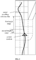
- a current position refers to a position at which a vehicle is currently located. Since a vehicle always travels along a travelling reference line, the current position of the vehicle is a certain position on the initial travelling reference line. For example, see FIG. 2 , which illustrates an initial travelling reference line with a certain length and the current position of a vehicle. A selected travelling reference line segment covering a first length range is also illustrated in FIG. 2 .
- both the first length range and the second length range may be set based on actual conditions.
- the first length range may be a range with a length of 200 m and the second length range may be a range with a length of 20 m.
- the second length range has a same starting point as the first length range. As illustrated in FIG. 2 , the second length range has a same starting point as the first length range, and the second length range is a smaller than the first length range.
- At least one sampling point is determined.
- the sampling point may include multiple sampling points selected longitudinally and transversely within the lane range.
- at least one sampling point may be further determined within a transverse (i.e., along a vehicle travelling direction) expansion range and a longitudinal (i.e., perpendicular to the vehicle travelling direction) expansion range of the corresponding lane, respectively, to obtain all of the sampling points within the first length range.
- At least one reference curve covering the first length range may be generated based on the determined at least one sampling point. Specifically, along a travelling direction of a vehicle, parts of the sampling points are selected from the at least one sampling point, and at least one reference curve passing through these sampling points may be generated. Each time, different sampling points may be selected for combination. However, the sampling points selected each time are at least partially different from each other. The principle of selecting sampling points each time may be to select a single sampling point in a direction perpendicular to the travelling direction. For example, referring to FIG. 3 , sampling points 1, 4 and 6 may be selected when a curve is to be generated, and sampling points 1, 3 and 6 may be selected when another curve is to be generated. Other possible combinations are not listed here in detail. As illustrated in FIG.
- At least one reference curve may be generated based on the sampling point selected each time. It should be understood that although some curves in the drawing are partially overlapped and the trend of each curve is not clearly illustrated, it may be deemed that multiple curves may pass through a same sampling point.
- selecting a target reference curve covering the first length range from the at least one reference curve covering the first length range includes:
- the obstacle may be an obstacle located within the lane range.
- an obstacle may be a vehicle, a person, an animal, and the like.
- any object, as long as it is located within a lane range, may be understood as an obstacle.
- any range covered by the lanes included in the first length range may be understood as the first length range.
- the position information of the at least one obstacle within the first length range may be acquired in real time.
- the real-time acquisition may be realized by a detection with a detection unit provided on the vehicle.
- the real-time acquisition may be realized by a real-time detection with an infrared detector or a camera.
- the acquisition of the position information of the obstacle may also be realized by a network-side server.
- a roadside unit may acquire information, which is captured by a device such as a camera provided on a road.
- the network-side server may process the information acquired by the roadside unit, to finally acquire the location information of the obstacle.
- the server may send it to a vehicle for further processing.
- the server may send the position information of all obstacles currently present on a road to the vehicle without distinction.
- the vehicle performs an extraction, to obtain the position information of the at least one obstacle within the first length range.
- the position information of both the vehicle and the obstacle may be represented with a same coordinate system, such as a world coordinate system or a coordinate system used for high-precision maps, which is not limited herein.
- the selecting a reference curve from the at least one reference curve covering the first length range as the target reference curve, based on the position information of the at least one obstacle within the first length range, wherein the target reference curve is a reference curve with a minimum path cost, which is used for avoiding the at least one obstacle, may be realized by means of a dynamic planning.
- C( i, j ) represents an j-th curve on an i-th layer.
- a group of ⁇ (i, j) ⁇ may be determined by using a dynamic planning algorithm, to find out a continuous path with a lowest cost.
- the driverless vehicle is the vehicle on the left.
- a vehicle i.e., an obstacle
- a target reference curve is selected by means of a dynamic planning.
- a curve to be adjusted covering the second length range is extracted from the target reference curve covering the first length range, wherein the second length range is smaller than the first length range and the second length range has a same starting point as the first length range.
- a curve covering a second length range is selected from the target reference curve covering a first length range as a curve to be adjusted, based on a same starting point.
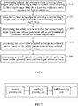
- the target reference curve is further processed by a method in combination with a quadratic planning. Specifically, on the basis of S101 and S102 described above, as illustrated in FIG. 6 , the method further includes the following steps.
- the safety parameter within the second length range is determined based on a vehicle parameter and an environmental parameter within the second length range.
- the curve to be adjusted is processed to obtain the adjusted curve, based on the safety parameter within the second length range.
- the vehicle parameter may be a dimension parameter of a vehicle, such as a length, a width or a height of a vehicle.
- the environmental parameter may include various parameters.
- the environmental parameter may include the position information of the obstacle within the lane range described above, and the position information of a static object outside the lane range, such as a road shoulder, a fence.
- the safety parameter within the second length range may be determined based on the vehicle parameter and the environmental parameter within the second length range. That is, based on the above vehicle parameter and the environmental parameter, a safety distance that the vehicle may avoid a static or dynamic obstacle or object is determined, and the safety distance may be considered as the safety parameter.
- a quality and a score of the curve are calculated by J, minimize means to select an J value with a lowest cost, and x represents a curve parameter.
- H, A and b are preset parameters
- b may be a safety parameter
- A may be a distance from a static or dynamic object, such as an obstacle or a road shoulder, to the curve to be adjusted.
- the determining a travelling path covering the first length range based on the adjusted curve and the target reference curve includes: splicing the adjusted curve with a part of the target reference curve outside the second length range, to obtain the travelling path covering the first length range.
- the adjusted curve within the second length range may be spliced with the rest of the target reference curve outside the second length range, to obtain an entire travelling path covering the first length range.
- the above process may be executed periodically.
- the interval between two executions may be set according to the actual situation. For example, it may be set to once every 1 minute, once every 5 minutes, and the like.
- the periodic execution indicates that the method according to the embodiment of the application is always re-executed from S101, regardless of whether the current travelling path within the first length range has been passed or not. Further, the previous travelling path, which has not been passed completely, may be deleted. The planning result of a corresponding travelling path is re-obtained then, based on an initial travelling reference line and a current position of a vehicle, details are not repeated here again.
- the method includes determining the target reference curve as the travelling path covering the first length range, when the processing of the curve to be adjusted based on the safety parameter within the second length range is failed. That is, when performing of the process at S103 or S1031 is failed, the target reference curve obtained by performing S101 may be directly taken as the final travelling path.
- a travelling reference curve may be adjusted in a wide range first, to get a target reference curve, which is used for avoiding an obstacle, and then, based on a safety parameter, an adjustment may be made in a small range, to obtain a final determined travelling path.
- the complexity of an actual traffic scene may be taken into account, and the safety of a path may be adjusted, so that the final determined travelling path may not be affected by the accuracy of sampling points, thereby improving the reliability and accuracy of a travelling path.
- an apparatus for planning a travelling path illustrated in FIG. 7 includes:
- the dynamic planning unit 71 is configured to select, based on a current position, a travelling reference line segment covering the first length range from the current position, on an initial travelling reference line; determine at least one sampling point based on the travelling reference line segment; and generate the at least one reference curve covering the first length range based on the determined at least one sampling point.
- the dynamic planning unit 71 is configured to acquire position information of at least one obstacle within the first length range; and select a reference curve from the at least one reference curve covering the first length range as the target reference curve, based on the position information of the at least one obstacle within the first length range, wherein the target reference curve is a reference curve with a minimum path cost, which is used for avoiding the at least one obstacle.
- the quadratic planning unit 72 is configured to determine the safety parameter within the second length range based on a vehicle parameter and an environmental parameter within the second length range; and process the curve to be adjusted to obtain the adjusted curve, based on the safety parameter within the second length range.
- the path processing unit 73 is configured to splice the adjusted curve with a part of the target reference curve outside the second length range, to obtain the travelling path covering the first length range.
- the path processing unit 73 is configured to determine the target reference curve as the travelling path covering the first length range, when the processing of the curve to be adjusted based on the safety parameter within the second length range is failed.
- a travelling reference curve may be adjusted in a wide range first, to get a target reference curve, which is used for avoiding an obstacle, and then, based on a safety parameter, an adjustment may be made in a small range, to obtain a final determined travelling path.
- the complexity of an actual traffic scene may be taken into account, and the safety of a path may be adjusted, so that the final determined travelling path may not be affected by the accuracy of sampling points, thereby improving the reliability and accuracy of a travelling path.
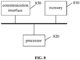
- FIG. 8 is a structural block diagram showing a vehicle according to an embodiment of the application.
- the vehicle includes a memory 810 and a processor 820, wherein a computer program that can run on the processor 820 is stored in the memory 810.
- the processor 820 executes the computer program to implement the method for planning a travelling path according to the foregoing embodiment.
- the number of either the memory 810 or the processor 820 may be one or more.
- the vehicle may further include a communication interface 930 configured to communicate with an external device and exchange data.
- the memory 810 may include a high-speed RAM memory and may also include a non-volatile memory, such as at least one magnetic disk memory.
- the bus may be an Industry Standard Architecture (ISA) bus, a Peripheral Component Interconnected (PCI) bus, an Extended Industry Standard Architecture (EISA) bus, or the like.
- ISA Industry Standard Architecture
- PCI Peripheral Component Interconnected
- EISA Extended Industry Standard Architecture
- the bus may be categorized into an address bus, a data bus, a control bus, and the like. For ease of illustration, only one bold line is shown in FIG. 8 to represent the bus, but it does not mean that there is only one bus or one type of bus.
- the memory 810, the processor 820 and the communication interface 830 may implement mutual communication through an internal interface.
- a computer-readable storage medium having computer programs stored thereon.
- the programs When executed by a processor, the programs implement the method for determining a driving path according to the foregoing embodiment.
- first and second are used for descriptive purposes only and are not to be construed as indicating or implying relative importance or implicitly indicating the number of indicated technical features. Thus, features defining “first” and “second” may explicitly or implicitly include at least one of the features. In the description of the present application, "a plurality of” means two or more, unless expressly limited otherwise.
- Logic and/or steps, which are represented in the flowcharts or otherwise described herein, for example, may be thought of as a sequencing listing of executable instructions for implementing logic functions, which may be embodied in any computer-readable medium, for use by or in connection with an instruction execution system, device, or apparatus (such as a computer-based system, a processor-included system, or other system that fetch instructions from an instruction execution system, device, or apparatus and execute the instructions).
- a "computer-readable medium” may be any device that may contain, store, communicate, propagate, or transport the program for use by or in connection with the instruction execution system, device, or apparatus.
- the computer readable medium of the embodiments of the present application may be a computer readable signal medium or a computer readable storage medium or any combination of the above. More specific examples (not a non-exhaustive list) of the computer-readable media include the following: electrical connections (electronic devices) having one or more wires, a portable computer disk cartridge (magnetic device), random access memory (RAM), read only memory (ROM), erasable programmable read only memory (EPROM or flash memory), optical fiber devices, and portable read only memory (CDROM).
- the computer-readable medium may even be paper or other suitable medium upon which the program may be printed, as it may be read, for example, by optical scanning of the paper or other medium, followed by editing, interpretation or, where appropriate, process otherwise to electronically obtain the program, which is then stored in a computer memory.
- each of the functional units in the embodiments of the present application may be integrated in one processing module, or each of the units may exist alone physically, or two or more units may be integrated in one module.
- the above-mentioned integrated module may be implemented in the form of hardware or in the form of software functional module.
- the integrated module When the integrated module is implemented in the form of a software functional module and is sold or used as an independent product, the integrated module may also be stored in a computer-readable storage medium.
- the storage medium may be a read only memory, a magnetic disk, an optical disk, or the like.
Landscapes
- Engineering & Computer Science (AREA)
- Automation & Control Theory (AREA)
- Radar, Positioning & Navigation (AREA)
- Remote Sensing (AREA)
- Physics & Mathematics (AREA)
- Transportation (AREA)
- Mechanical Engineering (AREA)
- General Physics & Mathematics (AREA)
- Human Computer Interaction (AREA)
- Chemical & Material Sciences (AREA)
- Analytical Chemistry (AREA)
- Aviation & Aerospace Engineering (AREA)
- Mathematical Physics (AREA)
- Traffic Control Systems (AREA)
- Control Of Driving Devices And Active Controlling Of Vehicle (AREA)
Abstract
Description
- The present application relates to a field of driverless control technology, and in particular, to a method and apparatus for planning a travelling path, and a vehicle.
- In the existing method for planning a travelling path of a driverless vehicle, a dynamic planning is often used for post-evaluation, to solve a discrete optimization problem. In this way, although it is ensured that a planning result may be obtained without failure, the quality of the planning result may be greatly affected by the sampling precision. Another way is to adopt a quadratic planning. However, in this way, it is difficult to take the complexity of an actual traffic scene into account and present it.
- A method and apparatus for planning a travelling path, and a vehicle are provided according to embodiments of the application, to solve the technical problems that the complexity of an actual traffic scene may not be taken into account and the path planning is greatly affected by the accuracy of sampling points.
- In a first aspect, a method for planning a travelling path is provided according to an embodiment of the application. The method includes:
- determining at least one reference curve covering a first length range, and selecting a target reference curve covering the first length range from the at least one reference curve covering the first length range, wherein the target reference curve is a curve which is used for avoiding any obstacle within the first length range;
- extracting a curve to be adjusted covering a second length range from the target reference curve covering the first length range, wherein the second length range is smaller than the first length range and the second length range has a same starting point as the first length range;
- processing the curve to be adjusted based on a safety parameter within the second length range, to obtain an adjusted curve; and
- determining a travelling path covering the first length range based on the adjusted curve and the target reference curve.
- In an implementation, the determining at least one reference curve covering a first length range includes:
- selecting, based on a current position, a travelling reference line segment covering the first length range from the current position, on an initial travelling reference line;
- determining at least one sampling point based on the travelling reference line segment; and
- generating the at least one reference curve covering the first length range based on the determined at least one sampling point.
- In an implementation, the selecting a target reference curve covering the first length range from the at least one reference curve covering the first length range includes:
- acquiring position information of at least one obstacle within the first length range; and
- selecting a reference curve from the at least one reference curve covering the first length range as the target reference curve, based on the position information of the at least one obstacle within the first length range, wherein the target reference curve is a reference curve with a minimum path cost, which is used for avoiding the at least one obstacle.
- In an implementation, the processing the curve to be adjusted based on a safety parameter within the second length range, to obtain an adjusted curve:
- determining the safety parameter within the second length range based on a vehicle parameter and an environmental parameter within the second length range; and
- processing the curve to be adjusted to obtain the adjusted curve, based on the safety parameter within the second length range.
- In an implementation, the determining a travelling path covering the first length range based on the adjusted curve and the target reference curve includes:
splicing the adjusted curve with a part of the target reference curve outside the second length range, to obtain the travelling path covering the first length range. - In an implementation, the method further includes:
determining the target reference curve as the travelling path covering the first length range, when the processing of the curve to be adjusted based on the safety parameter within the second length range is failed. - In a second aspect, an apparatus for planning a travelling path is provided according an embodiment of the application. The apparatus includes:
- a dynamic planning unit configured to determine at least one reference curve covering a first length range, and select a target reference curve covering the first length range from the at least one reference curve covering the first length range, wherein the target reference curve is a curve which is used for avoiding any obstacle within the first length range;
- a quadratic planning unit configured to extract a curve to be adjusted covering a second length range from the target reference curve covering the first length range, wherein the second length range is smaller than the first length range and the second length range has a same starting point as the first length range, and process the curve to be adjusted based on a safety parameter within the second length range, to obtain an adjusted curve; and
- a path processing unit configured to determine a travelling path covering the first length range based on the adjusted curve and the target reference curve.
- In an implementation, the dynamic planning unit is configured to select, based on a current position, a travelling reference line segment covering the first length range from the current position, on an initial travelling reference line; determine at least one sampling point based on the travelling reference line segment; and generate the at least one reference curve covering the first length range based on the determined at least one sampling point.
- In an implementation, the dynamic planning unit is configured to acquire position information of at least one obstacle within the first length range; and select a reference curve from the at least one reference curve covering the first length range as the target reference curve, based on the position information of the at least one obstacle within the first length range, wherein the target reference curve is a reference curve with a minimum path cost, which is used for avoiding the at least one obstacle.
- In an implementation, the quadratic planning unit is configured to determine the safety parameter within the second length range based on a vehicle parameter and an environmental parameter within the second length range; and
process the curve to be adjusted to obtain the adjusted curve, based on the safety parameter within the second length range. - In an implementation, the path processing unit is configured to splice the adjusted curve with a part of the target reference curve outside the second length range, to obtain the travelling path covering the first length range.
- In an implementation, the path processing unit is configured to determine the target reference curve as the travelling path covering the first length range, when the processing of the curve to be adjusted based on the safety parameter within the second length range is failed.
- In a third aspect, a vehicle is provided according an embodiment of the application. The functions of the vehicle may be implemented by using hardware or by corresponding software executed by hardware. The hardware or software includes one or more modules corresponding to the functions described above.
- In a possible embodiment, the vehicle structurally includes a processor and a storage, wherein the storage is configured to store a program which supports the apparatus in executing the above method for planning a travelling path. The processor is configured to execute the program stored in the memory. The apparatus may further include a communication interface for communicating with other devices or communication networks.
- In a fourth aspect, a computer readable storage medium for storing computer programs is provided according to an embodiment of the application. The programs are executed by a processor to implement the method according to the above embodiment.
- One of the above technical solutions has the following advantages or beneficial effects: a travelling reference curve may be adjusted in a wide range first, to get a target reference curve, which is used for avoiding an obstacle, and then, based on a safety parameter, an adjustment may be made in a small range, to obtain a final determined travelling path. In this way, upon planning a travelling path, the complexity of an actual traffic scene may be taken into account, and the safety of a path may be adjusted in real time, so that the final determined travelling path may not be affected by the accuracy of sampling points, thereby improving the reliability and accuracy of a travelling path.
- The above summary is provided only for illustration and is not intended to be limiting in any way. In addition to the illustrative aspects, embodiments, and features described above, further aspects, embodiments, and features of the present application will be readily understood from the following detailed description with reference to the accompanying drawings.
- In the drawings, unless otherwise specified, identical or similar parts or elements are denoted by identical reference numerals throughout the drawings. The drawings are not necessarily drawn to scale. It should be understood these drawings merely illustrate some embodiments of the present application and should not be construed as limiting the scope of the present application.
-
FIG. 1 is a flowchart 1 showing a method for planning a travelling path according to an embodiment of the application. -
FIG. 2 is a schematic diagram showing a scene of selecting a travelling reference line segment according to an embodiment of the application. -
FIG. 3 is a schematic diagram showing a scene of generating at least one curve according to an embodiment of the application. -
FIG. 4 is a schematic diagram showing a scene of selecting a target reference curve according to an embodiment of the application. -
FIG. 5 is a schematic diagram showing a scene of extracting a curve to be adjusted within a second length range from a target reference curve according to an embodiment of the application. -
FIG. 6 is a flowchart 2 showing a method for planning a travelling path according to an embodiment of the application. -
FIG. 7 is a schematic structural diagram showing an apparatus for planning a travelling path according to an embodiment of the application. -
FIG. 8 is a structural block diagram showing a vehicle according to an embodiment of the application. - Hereafter, only certain exemplary embodiments are briefly described. As can be appreciated by those skilled in the art, the described embodiments may be modified in different ways, without departing from the spirit or scope of the present application. Accordingly, the drawings and the description should be considered as illustrative in nature instead of being restrictive.
- A method for planning a travelling path is provided according to an embodiment of the application. In an implementation, as illustrated in
FIG. 1 , a method for planning a travelling path is provided. The method includes the following steps. - At S101, at least one reference curve covering a first length range is determined, and a target reference curve covering the first length range is selected from the at least one reference curve covering the first length range, wherein the target reference curve is a curve which is used for avoiding any obstacle within the first length range.
- At S102, a curve to be adjusted covering a second length range is extracted from the target reference curve covering the first length range, wherein the second length range is smaller than the first length range and the second length range has a same starting point as the first length range.
- At 103, the curve to be adjusted is processed based on a safety parameter within the second length range, to obtain an adjusted curve.
- At 104, a travelling path covering the first length range is determined based on the adjusted curve and the target reference curve.
- In the implementation, a processing scheme is proposed, wherein a wide range planning relies on a dynamic planning and a small range planning relies on a quadratic planning. Here, the dynamic planning is mainly used for planning a travelling path in a relatively long time period. A complex traffic scene may be expressed and modeled conveniently by sampling, to ensure a sufficient obstacle avoidance capability for a driverless vehicle.
- In the implementation, the dynamic planning is firstly explained below.
- At S101, the determining at least one reference curve covering a first length range includes:
- selecting, based on a current position, a travelling reference line segment covering the first length range from the current position, on an initial travelling reference line;
- determining at least one sampling point based on the travelling reference line segment; and
- generating the at least one reference curve covering the first length range based on the determined at least one sampling point.
- An initial travelling reference line may be a generated travelling reference line from a start point to an end point. An initial travelling reference line may also be generated as needed by a user.
- A current position refers to a position at which a vehicle is currently located. Since a vehicle always travels along a travelling reference line, the current position of the vehicle is a certain position on the initial travelling reference line. For example, see
FIG. 2 , which illustrates an initial travelling reference line with a certain length and the current position of a vehicle. A selected travelling reference line segment covering a first length range is also illustrated inFIG. 2 . - It should be understood that both the first length range and the second length range may be set based on actual conditions. For example, the first length range may be a range with a length of 200 m and the second length range may be a range with a length of 20 m. In addition, the second length range has a same starting point as the first length range. As illustrated in
FIG. 2 , the second length range has a same starting point as the first length range, and the second length range is a smaller than the first length range. - Based on the travelling reference line segment, at least one sampling point is determined. The sampling point may include multiple sampling points selected longitudinally and transversely within the lane range. After at least one sampling point is selected from the initial travelling reference line, at least one sampling point may be further determined within a transverse (i.e., along a vehicle travelling direction) expansion range and a longitudinal (i.e., perpendicular to the vehicle travelling direction) expansion range of the corresponding lane, respectively, to obtain all of the sampling points within the first length range.
- At least one reference curve covering the first length range may be generated based on the determined at least one sampling point. Specifically, along a travelling direction of a vehicle, parts of the sampling points are selected from the at least one sampling point, and at least one reference curve passing through these sampling points may be generated. Each time, different sampling points may be selected for combination. However, the sampling points selected each time are at least partially different from each other. The principle of selecting sampling points each time may be to select a single sampling point in a direction perpendicular to the travelling direction. For example, referring to
FIG. 3 , sampling points 1, 4 and 6 may be selected when a curve is to be generated, and sampling points 1, 3 and 6 may be selected when another curve is to be generated. Other possible combinations are not listed here in detail. As illustrated inFIG. 3 , at least one reference curve may be generated based on the sampling point selected each time. It should be understood that although some curves in the drawing are partially overlapped and the trend of each curve is not clearly illustrated, it may be deemed that multiple curves may pass through a same sampling point. - Further, the selecting a target reference curve covering the first length range from the at least one reference curve covering the first length range includes:
- acquiring position information of at least one obstacle within the first length range; and
- selecting a reference curve from the at least one reference curve covering the first length range as the target reference curve, based on the position information of the at least one obstacle within the first length range, wherein the target reference curve is a reference curve with a minimum path cost, which is used for avoiding the at least one obstacle.
- It should be noted that in the implementation, the obstacle may be an obstacle located within the lane range. For example, an obstacle may be a vehicle, a person, an animal, and the like. Further, any object, as long as it is located within a lane range, may be understood as an obstacle.
- Any range covered by the lanes included in the first length range may be understood as the first length range.
- The position information of the at least one obstacle within the first length range may be acquired in real time. The real-time acquisition may be realized by a detection with a detection unit provided on the vehicle. For example, the real-time acquisition may be realized by a real-time detection with an infrared detector or a camera. Alternatively, the acquisition of the position information of the obstacle may also be realized by a network-side server. Specifically, a roadside unit may acquire information, which is captured by a device such as a camera provided on a road. Then, the network-side server may process the information acquired by the roadside unit, to finally acquire the location information of the obstacle. After acquiring the position information of the at least one obstacle within the first length range, the server may send it to a vehicle for further processing. Alternatively, the server may send the position information of all obstacles currently present on a road to the vehicle without distinction. Then, the vehicle performs an extraction, to obtain the position information of the at least one obstacle within the first length range.
- In the above implementation, the position information of both the vehicle and the obstacle may be represented with a same coordinate system, such as a world coordinate system or a coordinate system used for high-precision maps, which is not limited herein.
- The selecting a reference curve from the at least one reference curve covering the first length range as the target reference curve, based on the position information of the at least one obstacle within the first length range, wherein the target reference curve is a reference curve with a minimum path cost, which is used for avoiding the at least one obstacle, may be realized by means of a dynamic planning. For example, C(i, j) represents an j-th curve on an i-th layer. Then, a group of {(i, j)} may be determined by using a dynamic planning algorithm, to find out a continuous path with a lowest cost.
- Referring to
FIG. 4 , the driverless vehicle is the vehicle on the left. There is a vehicle, i.e., an obstacle, within the first length range. Firstly, a target reference curve is selected by means of a dynamic planning. - Then, S102 is performed. That is, a curve to be adjusted covering the second length range is extracted from the target reference curve covering the first length range, wherein the second length range is smaller than the first length range and the second length range has a same starting point as the first length range. For example, referring to
FIG. 5 , a curve covering a second length range is selected from the target reference curve covering a first length range as a curve to be adjusted, based on a same starting point. - In an implementation, the target reference curve is further processed by a method in combination with a quadratic planning. Specifically, on the basis of S101 and S102 described above, as illustrated in
FIG. 6 , the method further includes the following steps. - At
S 1031, the safety parameter within the second length range is determined based on a vehicle parameter and an environmental parameter within the second length range. - At S1032, the curve to be adjusted is processed to obtain the adjusted curve, based on the safety parameter within the second length range.
- The vehicle parameter may be a dimension parameter of a vehicle, such as a length, a width or a height of a vehicle. The environmental parameter may include various parameters. For example, the environmental parameter may include the position information of the obstacle within the lane range described above, and the position information of a static object outside the lane range, such as a road shoulder, a fence.
- Then, the safety parameter within the second length range may be determined based on the vehicle parameter and the environmental parameter within the second length range. That is, based on the above vehicle parameter and the environmental parameter, a safety distance that the vehicle may avoid a static or dynamic obstacle or object is determined, and the safety distance may be considered as the safety parameter.
- Specifically, in the quadratic planning, the curve to be adjusted may be represented by a polynomial function 1 = f (w, s) in the Frenet Frame coordinate system, wherein w is a polynomial coefficient. Set x=w, then the quadratic planning may be performed by the following two calculations:

- In which, a quality and a score of the curve are calculated by J, minimize means to select an J value with a lowest cost, and x represents a curve parameter. In the above calculation formula, H, A and b are preset parameters, b may be a safety parameter, and A may be a distance from a static or dynamic object, such as an obstacle or a road shoulder, to the curve to be adjusted. Finally, the x obtained through the above calculation is the adjustment result, and the adjusted curve after adjustment may be obtained by bringing the x into 1 = f (w, s).
- The determining a travelling path covering the first length range based on the adjusted curve and the target reference curve includes: splicing the adjusted curve with a part of the target reference curve outside the second length range, to obtain the travelling path covering the first length range.
- That is to say, the adjusted curve within the second length range may be spliced with the rest of the target reference curve outside the second length range, to obtain an entire travelling path covering the first length range.
- It should be further pointed out that the above process may be executed periodically. The interval between two executions may be set according to the actual situation. For example, it may be set to once every 1 minute, once every 5 minutes, and the like. It may be understood that the periodic execution indicates that the method according to the embodiment of the application is always re-executed from S101, regardless of whether the current travelling path within the first length range has been passed or not. Further, the previous travelling path, which has not been passed completely, may be deleted. The planning result of a corresponding travelling path is re-obtained then, based on an initial travelling reference line and a current position of a vehicle, details are not repeated here again.
- Further, the method includes determining the target reference curve as the travelling path covering the first length range, when the processing of the curve to be adjusted based on the safety parameter within the second length range is failed. That is, when performing of the process at S103 or S1031 is failed, the target reference curve obtained by performing S101 may be directly taken as the final travelling path.
- It can be seen that by adopting the above solution, a travelling reference curve may be adjusted in a wide range first, to get a target reference curve, which is used for avoiding an obstacle, and then, based on a safety parameter, an adjustment may be made in a small range, to obtain a final determined travelling path. In this way, upon planning a travelling path, the complexity of an actual traffic scene may be taken into account, and the safety of a path may be adjusted, so that the final determined travelling path may not be affected by the accuracy of sampling points, thereby improving the reliability and accuracy of a travelling path.
- In an implementation, an apparatus for planning a travelling path illustrated in
FIG. 7 is provided. The apparatus includes: - a
dynamic planning unit 71 configured to determine at least one reference curve covering a first length range, and select a target reference curve covering the first length range from the at least one reference curve covering the first length range, wherein the target reference curve is a curve which is used for avoiding any obstacle within the first length range; - a quadratic planning unit 72 configured to extract a curve to be adjusted covering a second length range from the target reference curve covering the first length range, wherein the second length range is smaller than the first length range and the second length range has a same starting point as the first length range, and process the curve to be adjusted based on a safety parameter within the second length range, to obtain an adjusted curve; and
- a
path processing unit 73 configured to determine a travelling path covering the first length range based on the adjusted curve and the target reference curve. - The
dynamic planning unit 71 is configured to select, based on a current position, a travelling reference line segment covering the first length range from the current position, on an initial travelling reference line; determine at least one sampling point based on the travelling reference line segment; and generate the at least one reference curve covering the first length range based on the determined at least one sampling point. - The
dynamic planning unit 71 is configured to acquire position information of at least one obstacle within the first length range; and select a reference curve from the at least one reference curve covering the first length range as the target reference curve, based on the position information of the at least one obstacle within the first length range, wherein the target reference curve is a reference curve with a minimum path cost, which is used for avoiding the at least one obstacle. - The quadratic planning unit 72 is configured to determine the safety parameter within the second length range based on a vehicle parameter and an environmental parameter within the second length range; and process the curve to be adjusted to obtain the adjusted curve, based on the safety parameter within the second length range.
- The
path processing unit 73 is configured to splice the adjusted curve with a part of the target reference curve outside the second length range, to obtain the travelling path covering the first length range. - The
path processing unit 73 is configured to determine the target reference curve as the travelling path covering the first length range, when the processing of the curve to be adjusted based on the safety parameter within the second length range is failed. - In this embodiment, functions of modules in the apparatus refer to the corresponding description of the method mentioned above and thus a detailed description thereof is omitted herein.
- It can be seen that by adopting the above solution, a travelling reference curve may be adjusted in a wide range first, to get a target reference curve, which is used for avoiding an obstacle, and then, based on a safety parameter, an adjustment may be made in a small range, to obtain a final determined travelling path. In this way, upon planning a travelling path, the complexity of an actual traffic scene may be taken into account, and the safety of a path may be adjusted, so that the final determined travelling path may not be affected by the accuracy of sampling points, thereby improving the reliability and accuracy of a travelling path.
-
FIG. 8 is a structural block diagram showing a vehicle according to an embodiment of the application. As shown inFIG. 8 , the vehicle includes amemory 810 and aprocessor 820, wherein a computer program that can run on theprocessor 820 is stored in thememory 810. Theprocessor 820 executes the computer program to implement the method for planning a travelling path according to the foregoing embodiment. The number of either thememory 810 or theprocessor 820 may be one or more. - The vehicle may further include a communication interface 930 configured to communicate with an external device and exchange data.
- The
memory 810 may include a high-speed RAM memory and may also include a non-volatile memory, such as at least one magnetic disk memory. - If the
memory 810, theprocessor 820 and thecommunication interface 830 are implemented independently, thememory 810, theprocessor 820 and thecommunication interface 830 may be connected to each other via a bus to realize mutual communication. The bus may be an Industry Standard Architecture (ISA) bus, a Peripheral Component Interconnected (PCI) bus, an Extended Industry Standard Architecture (EISA) bus, or the like. The bus may be categorized into an address bus, a data bus, a control bus, and the like. For ease of illustration, only one bold line is shown inFIG. 8 to represent the bus, but it does not mean that there is only one bus or one type of bus. - Optionally, in a specific implementation, if the
memory 810, theprocessor 820 and thecommunication interface 830 are integrated on one chip, thememory 810, theprocessor 820 and thecommunication interface 830 may implement mutual communication through an internal interface. - In an embodiment of the present invention, it is provided a computer-readable storage medium having computer programs stored thereon. When executed by a processor, the programs implement the method for determining a driving path according to the foregoing embodiment.
- In the description of the specification, the description of the terms "one embodiment," "some embodiments," "an example," "a specific example," or "some examples" and the like means the specific features, structures, materials, or characteristics described in connection with the embodiment or example are included in at least one embodiment or example of the present application. Furthermore, the specific features, structures, materials, or characteristics described may be combined in any suitable manner in any one or more of the embodiments or examples. In addition, different embodiments or examples described in this specification and features of different embodiments or examples may be incorporated and combined by those skilled in the art without mutual contradiction.
- In addition, the terms "first" and "second" are used for descriptive purposes only and are not to be construed as indicating or implying relative importance or implicitly indicating the number of indicated technical features. Thus, features defining "first" and "second" may explicitly or implicitly include at least one of the features. In the description of the present application, "a plurality of" means two or more, unless expressly limited otherwise.
- Any process or method descriptions described in flowcharts or otherwise herein may be understood as representing modules, segments or portions of code that include one or more executable instructions for implementing the steps of a particular logic function or process. The scope of the preferred embodiments of the present application includes additional implementations where the functions may not be performed in the order shown or discussed, including according to the functions involved, in substantially simultaneous or in reverse order, which should be understood by those skilled in the art to which the embodiment of the present application belongs.
- Logic and/or steps, which are represented in the flowcharts or otherwise described herein, for example, may be thought of as a sequencing listing of executable instructions for implementing logic functions, which may be embodied in any computer-readable medium, for use by or in connection with an instruction execution system, device, or apparatus (such as a computer-based system, a processor-included system, or other system that fetch instructions from an instruction execution system, device, or apparatus and execute the instructions). For the purposes of this specification, a "computer-readable medium" may be any device that may contain, store, communicate, propagate, or transport the program for use by or in connection with the instruction execution system, device, or apparatus. The computer readable medium of the embodiments of the present application may be a computer readable signal medium or a computer readable storage medium or any combination of the above. More specific examples (not a non-exhaustive list) of the computer-readable media include the following: electrical connections (electronic devices) having one or more wires, a portable computer disk cartridge (magnetic device), random access memory (RAM), read only memory (ROM), erasable programmable read only memory (EPROM or flash memory), optical fiber devices, and portable read only memory (CDROM). In addition, the computer-readable medium may even be paper or other suitable medium upon which the program may be printed, as it may be read, for example, by optical scanning of the paper or other medium, followed by editing, interpretation or, where appropriate, process otherwise to electronically obtain the program, which is then stored in a computer memory.
- It should be understood various portions of the present application may be implemented by hardware, software, firmware, or a combination thereof. In the above embodiments, multiple steps or methods may be implemented in software or firmware stored in memory and executed by a suitable instruction execution system. For example, if implemented in hardware, as in another embodiment, they may be implemented using any one or a combination of the following techniques well known in the art: discrete logic circuits having a logic gate circuit for implementing logic functions on data signals, application specific integrated circuits with suitable combinational logic gate circuits, programmable gate arrays (PGA), field programmable gate arrays (FPGAs), and the like.
- Those skilled in the art may understand that all or some of the steps carried in the methods in the foregoing embodiments may be implemented by a program instructing relevant hardware. The program may be stored in a computer-readable storage medium, and when executed, one of the steps of the method embodiment or a combination thereof is included.
- In addition, each of the functional units in the embodiments of the present application may be integrated in one processing module, or each of the units may exist alone physically, or two or more units may be integrated in one module. The above-mentioned integrated module may be implemented in the form of hardware or in the form of software functional module. When the integrated module is implemented in the form of a software functional module and is sold or used as an independent product, the integrated module may also be stored in a computer-readable storage medium. The storage medium may be a read only memory, a magnetic disk, an optical disk, or the like.
- The foregoing descriptions are merely specific embodiments of the present application, but not intended to limit the protection scope of the present application. Those skilled in the art may easily conceive of various changes or modifications within the technical scope disclosed herein, all these should be covered within the protection scope of the present application. Therefore, the protection scope of the present application should be subject to the protection scope of the claims.
Claims (14)
- A method for planning a travelling path, comprising:determining (101) at least one reference curve covering a first length range, and selecting a target reference curve covering the first length range from the at least one reference curve covering the first length range, wherein the target reference curve is a curve which is used for avoiding any obstacle within the first length range;extracting (102) a curve to be adjusted covering a second length range from the target reference curve covering the first length range, wherein the second length range is smaller than the first length range and the second length range has a same starting point as the first length range;processing (103) the curve to be adjusted based on a safety parameter within the second length range, to obtain an adjusted curve; anddetermining (104) a travelling path covering the first length range based on the adjusted curve and the target reference curve.
- The method according to claim 1, wherein the determining at least one reference curve covering a first length range comprises:selecting, based on a current position, a travelling reference line segment covering the first length range from the current position, on an initial travelling reference line;determining at least one sampling point based on the travelling reference line segment; andgenerating the at least one reference curve covering the first length range based on the determined at least one sampling point.
- The method according to claim 1 or 2, wherein the selecting a target reference curve covering the first length range from the at least one reference curve covering the first length range comprises:acquiring position information of at least one obstacle within the first length range; andselecting a reference curve from the at least one reference curve covering the first length range as the target reference curve, based on the position information of the at least one obstacle within the first length range, wherein the target reference curve is a reference curve with a minimum path cost, which is used for avoiding the at least one obstacle.
- The method according to claim 1, wherein the processing the curve to be adjusted based on a safety parameter within the second length range, to obtain an adjusted curve comprises:determining (1031) the safety parameter within the second length range based on a vehicle parameter and an environmental parameter within the second length range; andprocessing (1032) the curve to be adjusted to obtain the adjusted curve, based on the safety parameter within the second length range.
- The method according to claim 1, wherein the determining a travelling path covering the first length range based on the adjusted curve and the target reference curve comprises:
splicing the adjusted curve with a part of the target reference curve outside the second length range, to obtain the travelling path covering the first length range. - The method according to any one of claims 1 to 5, further comprising:
determining the target reference curve as the travelling path covering the first length range, when the processing of the curve to be adjusted based on the safety parameter within the second length range is failed. - An apparatus for planning a travelling path, comprising:a dynamic planning unit (71) configured to determine at least one reference curve covering a first length range, and select a target reference curve covering the first length range from the at least one reference curve covering the first length range, wherein the target reference curve is a curve which is used for avoiding any obstacle within the first length range;a quadratic planning unit (72) configured to extract a curve to be adjusted covering a second length range from the target reference curve covering the first length range, wherein the second length range is smaller than the first length range and the second length range has a same starting point as the first length range, and process the curve to be adjusted based on a safety parameter within the second length range, to obtain an adjusted curve; anda path processing unit (73) configured to determine a travelling path covering the first length range based on the adjusted curve and the target reference curve.
- The apparatus according to claim 7, wherein the dynamic planning unit (71) is configured to select, based on a current position, a travelling reference line segment covering the first length range from the current position, on an initial travelling reference line; determine at least one sampling point based on the travelling reference line segment; and generate the at least one reference curve covering the first length range based on the determined at least one sampling point.
- The apparatus according to claim 7, wherein the dynamic planning unit (71) is configured to acquire position information of at least one obstacle within the first length range; and select a reference curve from the at least one reference curve covering the first length range as the target reference curve, based on the position information of the at least one obstacle within the first length range, wherein the target reference curve is a reference curve with a minimum path cost, which is used for avoiding the at least one obstacle.
- The apparatus according to claim 7, wherein the quadratic planning unit (72) is configured to determine the safety parameter within the second length range based on a vehicle parameter and an environmental parameter within the second length range; and
process the curve to be adjusted to obtain the adjusted curve, based on the safety parameter within the second length range. - The apparatus according to claim 7, wherein the path processing unit (73) is configured to splice the adjusted curve with a part of the target reference curve outside the second length range, to obtain the travelling path covering the first length range.
- The apparatus according to any one of claims 7 to 11, wherein the path processing unit (73) is configured to determine the target reference curve as the travelling path covering the first length range, when the processing of the curve to be adjusted based on the safety parameter within the second length range is failed.
- A vehicle, comprising:one or more processors (820); anda storage device configured to store one or more programs, whereinthe one or more programs, when executed by the one or more processors (820), cause the one or more processors (820) to implement the method according to any one of claims 1 to 6.
- A computer program product comprising computer executable instructions stored thereon, wherein the executable instructions, when executed by a processor (820), cause the processor (820) to implement the method according to any one of claims 1 to 6.
Applications Claiming Priority (1)
| Application Number | Priority Date | Filing Date | Title |
|---|---|---|---|
| CN201910133965.0A CN109813328B (en) | 2019-02-22 | 2019-02-22 | Driving path planning method and device and vehicle |
Publications (2)
| Publication Number | Publication Date |
|---|---|
| EP3702230A1 true EP3702230A1 (en) | 2020-09-02 |
| EP3702230B1 EP3702230B1 (en) | 2023-05-17 |
Family
ID=66607255
Family Applications (1)
| Application Number | Title | Priority Date | Filing Date |
|---|---|---|---|
| EP20158995.9A Active EP3702230B1 (en) | 2019-02-22 | 2020-02-24 | Method and apparatus for planning travelling path, and vehicle |
Country Status (5)
| Country | Link |
|---|---|
| US (1) | US11415994B2 (en) |
| EP (1) | EP3702230B1 (en) |
| JP (1) | JP7132960B2 (en) |
| KR (1) | KR102398456B1 (en) |
| CN (1) | CN109813328B (en) |
Cited By (1)
| Publication number | Priority date | Publication date | Assignee | Title |
|---|---|---|---|---|
| CN113320543A (en) * | 2021-06-29 | 2021-08-31 | 东软睿驰汽车技术(沈阳)有限公司 | Driving method, device, vehicle and storage medium |
Families Citing this family (21)
| Publication number | Priority date | Publication date | Assignee | Title |
|---|---|---|---|---|
| CN109765902B (en) * | 2019-02-22 | 2022-10-11 | 阿波罗智能技术(北京)有限公司 | Unmanned vehicle driving reference line processing method and device and vehicle |
| CN110749333B (en) * | 2019-11-07 | 2022-02-22 | 中南大学 | Unmanned vehicle motion planning method based on multi-objective optimization |
| CN111380556B (en) * | 2020-03-03 | 2022-04-01 | 北京百度网讯科技有限公司 | Information processing method and device for automatic driving vehicle |
| CN111473795B (en) * | 2020-04-08 | 2022-05-17 | 江苏盛海智能科技有限公司 | Obstacle avoidance method and terminal for unmanned vehicle |
| CN113804196B (en) * | 2020-09-17 | 2024-04-12 | 北京京东乾石科技有限公司 | Unmanned vehicle path planning method and related equipment |
| US11886195B2 (en) * | 2020-11-30 | 2024-01-30 | Woven By Toyota, U.S., Inc. | Active learning and validation system for vehicles |
| CN112550287B (en) * | 2020-12-16 | 2022-08-26 | 重庆大学 | Driving risk assessment method for structured road |
| CN112572443B (en) * | 2020-12-22 | 2021-12-07 | 北京理工大学 | Real-time collision-avoidance trajectory planning method and system for lane changing of vehicles on highway |
| CN112987724B (en) * | 2021-02-04 | 2023-05-02 | 京东科技信息技术有限公司 | Path optimization method, path optimization device, robot and storage medium |
| CN113091750B (en) * | 2021-04-12 | 2023-04-07 | 京东科技信息技术有限公司 | Local path planning method, device, computer equipment and storage medium |
| CN113447042B (en) * | 2021-05-20 | 2024-07-12 | 深圳大学 | A method, device, terminal and storage medium for detecting data mileage registration |
| CN113538683A (en) * | 2021-07-28 | 2021-10-22 | 视伴科技(北京)有限公司 | A method and device for determining the planned position of an entity streamline |
| DE102021211164A1 (en) * | 2021-10-04 | 2023-04-06 | Continental Autonomous Mobility Germany GmbH | Method for planning a trajectory of a driving maneuver of a motor vehicle, computer program product, computer-readable storage medium and vehicle |
| CN114442495B (en) * | 2021-12-07 | 2025-05-16 | 深圳市志凌伟业技术股份有限公司 | Method, device and computer-readable storage medium for generating adjustment parameters |
| CN114132325B (en) * | 2021-12-14 | 2024-03-01 | 京东鲲鹏(江苏)科技有限公司 | Method and device for driving vehicle |
| CN114527758A (en) * | 2022-02-24 | 2022-05-24 | 北京百度网讯科技有限公司 | Path planning method and device, equipment, medium and product |
| CN114506343B (en) * | 2022-03-02 | 2024-07-16 | 阿波罗智能技术(北京)有限公司 | Trajectory planning method, device, equipment, storage medium and autonomous driving vehicle |
| KR102445049B1 (en) * | 2022-04-15 | 2022-09-21 | 국방과학연구소 | Model predictive control method and model predictive control system for single neural network estimation autonomous vehicle |
| CN115257811B (en) * | 2022-08-11 | 2026-04-28 | 智道网联科技(北京)有限公司 | Path selection methods, devices, and electronic equipment for autonomous vehicles |
| CN115235476B (en) * | 2022-09-26 | 2023-01-17 | 宁波均胜智能汽车技术研究院有限公司 | Full-coverage path planning method and device, storage medium and electronic equipment |
| CN116136417B (en) * | 2023-04-14 | 2023-08-22 | 北京理工大学 | Unmanned vehicle local path planning method facing off-road environment |
Citations (2)
| Publication number | Priority date | Publication date | Assignee | Title |
|---|---|---|---|---|
| US20150073663A1 (en) * | 2013-09-12 | 2015-03-12 | Volvo Car Corporation | Manoeuver generation for automated driving |
| WO2018061612A1 (en) * | 2016-09-29 | 2018-04-05 | 本田技研工業株式会社 | Vehicle control device |
Family Cites Families (40)
| Publication number | Priority date | Publication date | Assignee | Title |
|---|---|---|---|---|
| JP3470453B2 (en) * | 1995-04-06 | 2003-11-25 | 株式会社デンソー | Inter-vehicle distance control device |
| JP6040638B2 (en) | 2012-08-28 | 2016-12-07 | 日産自動車株式会社 | Vehicle travel control apparatus and method |
| DE102013013867A1 (en) * | 2013-08-20 | 2015-03-12 | Audi Ag | Motor vehicle and method for controlling a motor vehicle |
| CN103760904B (en) * | 2014-02-13 | 2016-10-19 | 北京工业大学 | A kind of voice broadcast type intelligent vehicle path planning apparatus and implementation |
| US9623878B2 (en) * | 2014-04-02 | 2017-04-18 | Magna Electronics Inc. | Personalized driver assistance system for vehicle |
| CN104238560B (en) * | 2014-09-26 | 2017-04-05 | 深圳市中智科创机器人有限公司 | A kind of nonlinear path method and system for planning |
| US9499197B2 (en) * | 2014-10-15 | 2016-11-22 | Hua-Chuang Automobile Information Technical Center Co., Ltd. | System and method for vehicle steering control |
| JP6447639B2 (en) * | 2015-01-05 | 2019-01-09 | 日産自動車株式会社 | Target route generation device and travel control device |
| CN111380545B (en) * | 2015-02-10 | 2024-11-12 | 御眼视觉技术有限公司 | Method, server, autonomous vehicle and medium for autonomous vehicle navigation |
| JP6361567B2 (en) * | 2015-04-27 | 2018-07-25 | トヨタ自動車株式会社 | Automated driving vehicle system |
| US9821801B2 (en) | 2015-06-29 | 2017-11-21 | Mitsubishi Electric Research Laboratories, Inc. | System and method for controlling semi-autonomous vehicles |
| JP6323402B2 (en) * | 2015-07-01 | 2018-05-16 | 株式会社デンソー | In-lane travel control device, in-lane travel control method |
| US9620015B2 (en) * | 2015-07-13 | 2017-04-11 | Nissan North America, Inc. | Kinematic path prediction of vehicles on curved paths |
| CN107851392B (en) | 2015-07-22 | 2021-04-09 | 本田技研工业株式会社 | Path generation device, path generation method, and medium storing path generation program |
| JP6303217B2 (en) * | 2015-10-28 | 2018-04-04 | 本田技研工業株式会社 | Vehicle control device, vehicle control method, and vehicle control program |
| JP2017087856A (en) | 2015-11-05 | 2017-05-25 | マツダ株式会社 | Vehicle control device |
| JP6558239B2 (en) * | 2015-12-22 | 2019-08-14 | アイシン・エィ・ダブリュ株式会社 | Automatic driving support system, automatic driving support method, and computer program |
| US20190016339A1 (en) * | 2016-02-16 | 2019-01-17 | Honda Motor Co., Ltd. | Vehicle control device, vehicle control method, and vehicle control program |
| US9851212B2 (en) * | 2016-05-06 | 2017-12-26 | Ford Global Technologies, Llc | Route generation using road lane line quality |
| JP6638556B2 (en) | 2016-05-20 | 2020-01-29 | アイシン・エィ・ダブリュ株式会社 | Automatic driving support device and computer program |
| CN106114507B (en) * | 2016-06-21 | 2018-04-03 | 百度在线网络技术(北京)有限公司 | Local path planning method and device for intelligent vehicle |
| CN107664502A (en) | 2016-07-28 | 2018-02-06 | 奥迪股份公司 | The method, apparatus and system of dynamic programming path |
| JP6715343B2 (en) * | 2016-10-26 | 2020-07-01 | 本田技研工業株式会社 | Vehicle control device |
| JP6428746B2 (en) * | 2016-11-07 | 2018-11-28 | 本田技研工業株式会社 | Vehicle control system, vehicle control method, and vehicle control program |
| JP6695999B2 (en) * | 2016-11-11 | 2020-05-20 | 本田技研工業株式会社 | Vehicle control system, vehicle control method, and vehicle control program |
| WO2018122998A1 (en) * | 2016-12-28 | 2018-07-05 | 富士通株式会社 | Route information provision device, route search device, route information provision system, route information provision program, and route information provision method |
| JP2018138404A (en) | 2017-02-24 | 2018-09-06 | マツダ株式会社 | Vehicle driving assisting system and method |
| US11067995B2 (en) * | 2017-03-20 | 2021-07-20 | Mobileye Vision Technologies Ltd. | Navigation by augmented path prediction |
| DE102017205508A1 (en) * | 2017-03-31 | 2018-10-04 | Robert Bosch Gmbh | Method for automatic movement control of a vehicle |
| JP6805965B2 (en) | 2017-05-23 | 2020-12-23 | トヨタ自動車株式会社 | Collision avoidance control device |
| US20210146943A1 (en) * | 2017-06-02 | 2021-05-20 | Honda Motor Co., Ltd. | Vehicle control system, vehicle control method, and vehicle control program |
| CN110709304B (en) * | 2017-06-02 | 2023-01-06 | 本田技研工业株式会社 | Vehicle control system, vehicle control method, and storage medium |
| CN110770809B (en) | 2017-06-20 | 2022-08-09 | 三菱电机株式会社 | Route prediction device and route prediction method |
| US10274961B2 (en) * | 2017-07-26 | 2019-04-30 | GM Global Technology Operations LLC | Path planning for autonomous driving |
| CN107992050B (en) * | 2017-12-20 | 2021-05-11 | 广州汽车集团股份有限公司 | Method and device for local path motion planning of unmanned vehicle |
| CN108334086B (en) * | 2018-01-25 | 2021-06-22 | 江苏大学 | Unmanned vehicle path tracking control method based on soft-constraint quadratic programming MPC |
| JP2019156193A (en) * | 2018-03-14 | 2019-09-19 | 本田技研工業株式会社 | Vehicle controller |
| CN109318890A (en) * | 2018-06-29 | 2019-02-12 | 北京理工大学 | A dynamic obstacle avoidance method for unmanned vehicles based on dynamic windows and potential energy fields of obstacles |
| CN109765902B (en) * | 2019-02-22 | 2022-10-11 | 阿波罗智能技术(北京)有限公司 | Unmanned vehicle driving reference line processing method and device and vehicle |
| US11525691B2 (en) * | 2019-09-20 | 2022-12-13 | Samsung Electronics Co., Ltd. | System and method for autonomous motion planning |
-
2019
- 2019-02-22 CN CN201910133965.0A patent/CN109813328B/en active Active
-
2020
- 2020-02-17 US US16/792,645 patent/US11415994B2/en active Active
- 2020-02-21 JP JP2020027726A patent/JP7132960B2/en active Active
- 2020-02-21 KR KR1020200021596A patent/KR102398456B1/en active Active
- 2020-02-24 EP EP20158995.9A patent/EP3702230B1/en active Active
Patent Citations (3)
| Publication number | Priority date | Publication date | Assignee | Title |
|---|---|---|---|---|
| US20150073663A1 (en) * | 2013-09-12 | 2015-03-12 | Volvo Car Corporation | Manoeuver generation for automated driving |
| WO2018061612A1 (en) * | 2016-09-29 | 2018-04-05 | 本田技研工業株式会社 | Vehicle control device |
| US20200033871A1 (en) * | 2016-09-29 | 2020-01-30 | Honda Motor Co., Ltd. | Vehicle control device |
Non-Patent Citations (1)
| Title |
|---|
| NIEUWENHUISEN MATTHIAS ET AL: "Local multiresolution trajectory optimization for micro aerial vehicles employing continuous curvature transitions", 2016 IEEE/RSJ INTERNATIONAL CONFERENCE ON INTELLIGENT ROBOTS AND SYSTEMS (IROS), IEEE, 9 October 2016 (2016-10-09), pages 3219 - 3224, XP033011847, DOI: 10.1109/IROS.2016.7759497 * |
Cited By (2)
| Publication number | Priority date | Publication date | Assignee | Title |
|---|---|---|---|---|
| CN113320543A (en) * | 2021-06-29 | 2021-08-31 | 东软睿驰汽车技术(沈阳)有限公司 | Driving method, device, vehicle and storage medium |
| CN113320543B (en) * | 2021-06-29 | 2024-03-22 | 东软睿驰汽车技术(沈阳)有限公司 | Driving method, driving device, vehicle and storage medium |
Also Published As
| Publication number | Publication date |
|---|---|
| KR102398456B1 (en) | 2022-05-16 |
| KR20200103561A (en) | 2020-09-02 |
| EP3702230B1 (en) | 2023-05-17 |
| CN109813328B (en) | 2021-04-30 |
| US11415994B2 (en) | 2022-08-16 |
| CN109813328A (en) | 2019-05-28 |
| JP7132960B2 (en) | 2022-09-07 |
| JP2020132154A (en) | 2020-08-31 |
| US20200272157A1 (en) | 2020-08-27 |
Similar Documents
| Publication | Publication Date | Title |
|---|---|---|
| US11415994B2 (en) | Method and apparatus for planning travelling path, and vehicle | |
| US11718318B2 (en) | Method and apparatus for planning speed of autonomous vehicle, and storage medium | |
| US11629964B2 (en) | Navigation map updating method and apparatus and robot using the same | |
| US20200265710A1 (en) | Travelling track prediction method and device for vehicle | |
| US11415993B2 (en) | Method and apparatus for processing driving reference line, and vehicle | |
| EP3703033A1 (en) | Track prediction method and device for obstacle at junction | |
| US11480967B2 (en) | Pass route planning method and apparatus, device and readable storage medium | |
| EP3709231A1 (en) | Vehicle track planning method, device, computer device and computer-readable storage medium | |
| US10984588B2 (en) | Obstacle distribution simulation method and device based on multiple models, and storage medium | |
| CN113859264B (en) | Vehicle control method, device, electronic equipment and storage medium | |
| JP2019102049A (en) | Method and device for lane detection | |
| CN111178215A (en) | Sensor data fusion processing method and device | |
| CN115116024B (en) | Verification method for lane marking, related generation method and related equipment | |
| JP2020042781A (en) | Multi focal length vision-based obstacle sensing method, device, facility and storage medium | |
| CN114926813A (en) | Lane line fusion method, device, equipment and storage medium | |
| CN116895061A (en) | Lane line processing method and device | |
| CN118057124A (en) | Automatic driving intersection path planning method and device and non-transitory computer readable storage medium | |
| CN108896065A (en) | A kind of automobile paths planning method, system, equipment and computer storage medium | |
| CN117533354B (en) | Trajectory generation method, driving control method, storage medium and intelligent device | |
| CN115950441B (en) | Fusion positioning method, device and electronic equipment for self-driving vehicles | |
| CN116045992B (en) | Navigation method and device for automatic driving vehicle, electronic equipment and storage medium | |
| CN118640904A (en) | Path planning method, device, electronic device, storage medium and program product | |
| CN115014333A (en) | Signal map construction method, device, electronic device, and storage medium | |
| US20250087093A1 (en) | Method and Apparatus for Generating Lane Boundary in Ego-Vehicle Ground Truth System | |
| CN118818565B (en) | Vehicle positioning method, apparatus, electronic device, storage medium, and computer program product |
Legal Events
| Date | Code | Title | Description |
|---|---|---|---|
| PUAI | Public reference made under article 153(3) epc to a published international application that has entered the european phase |
Free format text: ORIGINAL CODE: 0009012 |
|
| STAA | Information on the status of an ep patent application or granted ep patent |
Free format text: STATUS: REQUEST FOR EXAMINATION WAS MADE |
|
| 17P | Request for examination filed |
Effective date: 20200424 |
|
| AK | Designated contracting states |
Kind code of ref document: A1 Designated state(s): AL AT BE BG CH CY CZ DE DK EE ES FI FR GB GR HR HU IE IS IT LI LT LU LV MC MK MT NL NO PL PT RO RS SE SI SK SM TR |
|
| AX | Request for extension of the european patent |
Extension state: BA ME |
|
| STAA | Information on the status of an ep patent application or granted ep patent |
Free format text: STATUS: EXAMINATION IS IN PROGRESS |
|
| 17Q | First examination report despatched |
Effective date: 20210922 |
|
| RAP1 | Party data changed (applicant data changed or rights of an application transferred) |
Owner name: APOLLO INTELLIGENT DRIVING TECHNOLOGY (BEIJING) CO., LTD. |
|
| GRAP | Despatch of communication of intention to grant a patent |
Free format text: ORIGINAL CODE: EPIDOSNIGR1 |
|
| STAA | Information on the status of an ep patent application or granted ep patent |
Free format text: STATUS: GRANT OF PATENT IS INTENDED |
|
| INTG | Intention to grant announced |
Effective date: 20221206 |
|
| GRAS | Grant fee paid |
Free format text: ORIGINAL CODE: EPIDOSNIGR3 |
|
| GRAA | (expected) grant |
Free format text: ORIGINAL CODE: 0009210 |
|
| STAA | Information on the status of an ep patent application or granted ep patent |
Free format text: STATUS: THE PATENT HAS BEEN GRANTED |
|
| AK | Designated contracting states |
Kind code of ref document: B1 Designated state(s): AL AT BE BG CH CY CZ DE DK EE ES FI FR GB GR HR HU IE IS IT LI LT LU LV MC MK MT NL NO PL PT RO RS SE SI SK SM TR |
|
| REG | Reference to a national code |
Ref country code: GB Ref legal event code: FG4D |
|
| REG | Reference to a national code |
Ref country code: DE Ref legal event code: R096 Ref document number: 602020010878 Country of ref document: DE |
|
| REG | Reference to a national code |
Ref country code: CH Ref legal event code: EP |
|
| REG | Reference to a national code |
Ref country code: IE Ref legal event code: FG4D |
|
| REG | Reference to a national code |
Ref country code: AT Ref legal event code: REF Ref document number: 1568285 Country of ref document: AT Kind code of ref document: T Effective date: 20230615 |
|
| REG | Reference to a national code |
Ref country code: LT Ref legal event code: MG9D |
|
| REG | Reference to a national code |
Ref country code: NL Ref legal event code: MP Effective date: 20230517 |
|
| REG | Reference to a national code |
Ref country code: AT Ref legal event code: MK05 Ref document number: 1568285 Country of ref document: AT Kind code of ref document: T Effective date: 20230517 |
|
| PG25 | Lapsed in a contracting state [announced via postgrant information from national office to epo] |
Ref country code: SE Free format text: LAPSE BECAUSE OF FAILURE TO SUBMIT A TRANSLATION OF THE DESCRIPTION OR TO PAY THE FEE WITHIN THE PRESCRIBED TIME-LIMIT Effective date: 20230517 Ref country code: PT Free format text: LAPSE BECAUSE OF FAILURE TO SUBMIT A TRANSLATION OF THE DESCRIPTION OR TO PAY THE FEE WITHIN THE PRESCRIBED TIME-LIMIT Effective date: 20230918 Ref country code: NO Free format text: LAPSE BECAUSE OF FAILURE TO SUBMIT A TRANSLATION OF THE DESCRIPTION OR TO PAY THE FEE WITHIN THE PRESCRIBED TIME-LIMIT Effective date: 20230817 Ref country code: NL Free format text: LAPSE BECAUSE OF FAILURE TO SUBMIT A TRANSLATION OF THE DESCRIPTION OR TO PAY THE FEE WITHIN THE PRESCRIBED TIME-LIMIT Effective date: 20230517 Ref country code: ES Free format text: LAPSE BECAUSE OF FAILURE TO SUBMIT A TRANSLATION OF THE DESCRIPTION OR TO PAY THE FEE WITHIN THE PRESCRIBED TIME-LIMIT Effective date: 20230517 Ref country code: AT Free format text: LAPSE BECAUSE OF FAILURE TO SUBMIT A TRANSLATION OF THE DESCRIPTION OR TO PAY THE FEE WITHIN THE PRESCRIBED TIME-LIMIT Effective date: 20230517 |
|
| PG25 | Lapsed in a contracting state [announced via postgrant information from national office to epo] |
Ref country code: RS Free format text: LAPSE BECAUSE OF FAILURE TO SUBMIT A TRANSLATION OF THE DESCRIPTION OR TO PAY THE FEE WITHIN THE PRESCRIBED TIME-LIMIT Effective date: 20230517 Ref country code: PL Free format text: LAPSE BECAUSE OF FAILURE TO SUBMIT A TRANSLATION OF THE DESCRIPTION OR TO PAY THE FEE WITHIN THE PRESCRIBED TIME-LIMIT Effective date: 20230517 Ref country code: LV Free format text: LAPSE BECAUSE OF FAILURE TO SUBMIT A TRANSLATION OF THE DESCRIPTION OR TO PAY THE FEE WITHIN THE PRESCRIBED TIME-LIMIT Effective date: 20230517 Ref country code: LT Free format text: LAPSE BECAUSE OF FAILURE TO SUBMIT A TRANSLATION OF THE DESCRIPTION OR TO PAY THE FEE WITHIN THE PRESCRIBED TIME-LIMIT Effective date: 20230517 Ref country code: IS Free format text: LAPSE BECAUSE OF FAILURE TO SUBMIT A TRANSLATION OF THE DESCRIPTION OR TO PAY THE FEE WITHIN THE PRESCRIBED TIME-LIMIT Effective date: 20230917 Ref country code: HR Free format text: LAPSE BECAUSE OF FAILURE TO SUBMIT A TRANSLATION OF THE DESCRIPTION OR TO PAY THE FEE WITHIN THE PRESCRIBED TIME-LIMIT Effective date: 20230517 Ref country code: GR Free format text: LAPSE BECAUSE OF FAILURE TO SUBMIT A TRANSLATION OF THE DESCRIPTION OR TO PAY THE FEE WITHIN THE PRESCRIBED TIME-LIMIT Effective date: 20230818 |
|
| PG25 | Lapsed in a contracting state [announced via postgrant information from national office to epo] |
Ref country code: FI Free format text: LAPSE BECAUSE OF FAILURE TO SUBMIT A TRANSLATION OF THE DESCRIPTION OR TO PAY THE FEE WITHIN THE PRESCRIBED TIME-LIMIT Effective date: 20230517 |
|
| PG25 | Lapsed in a contracting state [announced via postgrant information from national office to epo] |
Ref country code: SK Free format text: LAPSE BECAUSE OF FAILURE TO SUBMIT A TRANSLATION OF THE DESCRIPTION OR TO PAY THE FEE WITHIN THE PRESCRIBED TIME-LIMIT Effective date: 20230517 |
|
| PG25 | Lapsed in a contracting state [announced via postgrant information from national office to epo] |
Ref country code: SM Free format text: LAPSE BECAUSE OF FAILURE TO SUBMIT A TRANSLATION OF THE DESCRIPTION OR TO PAY THE FEE WITHIN THE PRESCRIBED TIME-LIMIT Effective date: 20230517 Ref country code: SK Free format text: LAPSE BECAUSE OF FAILURE TO SUBMIT A TRANSLATION OF THE DESCRIPTION OR TO PAY THE FEE WITHIN THE PRESCRIBED TIME-LIMIT Effective date: 20230517 Ref country code: RO Free format text: LAPSE BECAUSE OF FAILURE TO SUBMIT A TRANSLATION OF THE DESCRIPTION OR TO PAY THE FEE WITHIN THE PRESCRIBED TIME-LIMIT Effective date: 20230517 Ref country code: EE Free format text: LAPSE BECAUSE OF FAILURE TO SUBMIT A TRANSLATION OF THE DESCRIPTION OR TO PAY THE FEE WITHIN THE PRESCRIBED TIME-LIMIT Effective date: 20230517 Ref country code: DK Free format text: LAPSE BECAUSE OF FAILURE TO SUBMIT A TRANSLATION OF THE DESCRIPTION OR TO PAY THE FEE WITHIN THE PRESCRIBED TIME-LIMIT Effective date: 20230517 Ref country code: CZ Free format text: LAPSE BECAUSE OF FAILURE TO SUBMIT A TRANSLATION OF THE DESCRIPTION OR TO PAY THE FEE WITHIN THE PRESCRIBED TIME-LIMIT Effective date: 20230517 |
|
| REG | Reference to a national code |
Ref country code: DE Ref legal event code: R097 Ref document number: 602020010878 Country of ref document: DE |
|
| PLBE | No opposition filed within time limit |
Free format text: ORIGINAL CODE: 0009261 |
|
| STAA | Information on the status of an ep patent application or granted ep patent |
Free format text: STATUS: NO OPPOSITION FILED WITHIN TIME LIMIT |
|
| 26N | No opposition filed |
Effective date: 20240220 |
|
| PG25 | Lapsed in a contracting state [announced via postgrant information from national office to epo] |
Ref country code: SI Free format text: LAPSE BECAUSE OF FAILURE TO SUBMIT A TRANSLATION OF THE DESCRIPTION OR TO PAY THE FEE WITHIN THE PRESCRIBED TIME-LIMIT Effective date: 20230517 |
|
| PG25 | Lapsed in a contracting state [announced via postgrant information from national office to epo] |
Ref country code: SI Free format text: LAPSE BECAUSE OF FAILURE TO SUBMIT A TRANSLATION OF THE DESCRIPTION OR TO PAY THE FEE WITHIN THE PRESCRIBED TIME-LIMIT Effective date: 20230517 Ref country code: IT Free format text: LAPSE BECAUSE OF FAILURE TO SUBMIT A TRANSLATION OF THE DESCRIPTION OR TO PAY THE FEE WITHIN THE PRESCRIBED TIME-LIMIT Effective date: 20230517 |
|
| PG25 | Lapsed in a contracting state [announced via postgrant information from national office to epo] |
Ref country code: MC Free format text: LAPSE BECAUSE OF FAILURE TO SUBMIT A TRANSLATION OF THE DESCRIPTION OR TO PAY THE FEE WITHIN THE PRESCRIBED TIME-LIMIT Effective date: 20230517 |
|
| REG | Reference to a national code |
Ref country code: CH Ref legal event code: PL |
|
| PG25 | Lapsed in a contracting state [announced via postgrant information from national office to epo] |
Ref country code: LU Free format text: LAPSE BECAUSE OF NON-PAYMENT OF DUE FEES Effective date: 20240224 |
|
| PG25 | Lapsed in a contracting state [announced via postgrant information from national office to epo] |
Ref country code: CH Free format text: LAPSE BECAUSE OF NON-PAYMENT OF DUE FEES Effective date: 20240229 |
|
| GBPC | Gb: european patent ceased through non-payment of renewal fee |
Effective date: 20240224 |
|
| PG25 | Lapsed in a contracting state [announced via postgrant information from national office to epo] |
Ref country code: LU Free format text: LAPSE BECAUSE OF NON-PAYMENT OF DUE FEES Effective date: 20240224 Ref country code: CH Free format text: LAPSE BECAUSE OF NON-PAYMENT OF DUE FEES Effective date: 20240229 |
|
| PG25 | Lapsed in a contracting state [announced via postgrant information from national office to epo] |
Ref country code: BG Free format text: LAPSE BECAUSE OF FAILURE TO SUBMIT A TRANSLATION OF THE DESCRIPTION OR TO PAY THE FEE WITHIN THE PRESCRIBED TIME-LIMIT Effective date: 20230517 |
|
| PG25 | Lapsed in a contracting state [announced via postgrant information from national office to epo] |
Ref country code: BG Free format text: LAPSE BECAUSE OF FAILURE TO SUBMIT A TRANSLATION OF THE DESCRIPTION OR TO PAY THE FEE WITHIN THE PRESCRIBED TIME-LIMIT Effective date: 20230517 |
|
| REG | Reference to a national code |
Ref country code: BE Ref legal event code: MM Effective date: 20240229 |
|
| PG25 | Lapsed in a contracting state [announced via postgrant information from national office to epo] |
Ref country code: BE Free format text: LAPSE BECAUSE OF NON-PAYMENT OF DUE FEES Effective date: 20240229 |
|
| PG25 | Lapsed in a contracting state [announced via postgrant information from national office to epo] |
Ref country code: GB Free format text: LAPSE BECAUSE OF NON-PAYMENT OF DUE FEES Effective date: 20240224 |
|
| PG25 | Lapsed in a contracting state [announced via postgrant information from national office to epo] |
Ref country code: IE Free format text: LAPSE BECAUSE OF NON-PAYMENT OF DUE FEES Effective date: 20240224 |
|
| PG25 | Lapsed in a contracting state [announced via postgrant information from national office to epo] |
Ref country code: IE Free format text: LAPSE BECAUSE OF NON-PAYMENT OF DUE FEES Effective date: 20240224 Ref country code: GB Free format text: LAPSE BECAUSE OF NON-PAYMENT OF DUE FEES Effective date: 20240224 Ref country code: BE Free format text: LAPSE BECAUSE OF NON-PAYMENT OF DUE FEES Effective date: 20240229 |
|
| PG25 | Lapsed in a contracting state [announced via postgrant information from national office to epo] |
Ref country code: CY Free format text: LAPSE BECAUSE OF FAILURE TO SUBMIT A TRANSLATION OF THE DESCRIPTION OR TO PAY THE FEE WITHIN THE PRESCRIBED TIME-LIMIT; INVALID AB INITIO Effective date: 20200224 |
|
| PG25 | Lapsed in a contracting state [announced via postgrant information from national office to epo] |
Ref country code: HU Free format text: LAPSE BECAUSE OF FAILURE TO SUBMIT A TRANSLATION OF THE DESCRIPTION OR TO PAY THE FEE WITHIN THE PRESCRIBED TIME-LIMIT; INVALID AB INITIO Effective date: 20200224 |
|
| PG25 | Lapsed in a contracting state [announced via postgrant information from national office to epo] |
Ref country code: TR Free format text: LAPSE BECAUSE OF FAILURE TO SUBMIT A TRANSLATION OF THE DESCRIPTION OR TO PAY THE FEE WITHIN THE PRESCRIBED TIME-LIMIT Effective date: 20230517 |
|
| PGFP | Annual fee paid to national office [announced via postgrant information from national office to epo] |
Ref country code: DE Payment date: 20260217 Year of fee payment: 7 |
|
| PGFP | Annual fee paid to national office [announced via postgrant information from national office to epo] |
Ref country code: FR Payment date: 20260112 Year of fee payment: 7 |