EP3702173A1 - Caster module and robot - Google Patents
Caster module and robot Download PDFInfo
- Publication number
- EP3702173A1 EP3702173A1 EP20159686.3A EP20159686A EP3702173A1 EP 3702173 A1 EP3702173 A1 EP 3702173A1 EP 20159686 A EP20159686 A EP 20159686A EP 3702173 A1 EP3702173 A1 EP 3702173A1
- Authority
- EP
- European Patent Office
- Prior art keywords
- omni wheel
- bearing
- effector
- groove
- shaft
- Prior art date
- Legal status (The legal status is an assumption and is not a legal conclusion. Google has not performed a legal analysis and makes no representation as to the accuracy of the status listed.)
- Granted
Links
Images



Classifications
-
- B—PERFORMING OPERATIONS; TRANSPORTING
- B60—VEHICLES IN GENERAL
- B60B—VEHICLE WHEELS; CASTORS; AXLES FOR WHEELS OR CASTORS; INCREASING WHEEL ADHESION
- B60B19/00—Wheels not otherwise provided for or having characteristics specified in one of the subgroups of this group
- B60B19/003—Multidirectional wheels
-
- B—PERFORMING OPERATIONS; TRANSPORTING
- B25—HAND TOOLS; PORTABLE POWER-DRIVEN TOOLS; MANIPULATORS
- B25J—MANIPULATORS; CHAMBERS PROVIDED WITH MANIPULATION DEVICES
- B25J5/00—Manipulators mounted on wheels or on carriages
- B25J5/007—Manipulators mounted on wheels or on carriages mounted on wheels
-
- B—PERFORMING OPERATIONS; TRANSPORTING
- B25—HAND TOOLS; PORTABLE POWER-DRIVEN TOOLS; MANIPULATORS
- B25J—MANIPULATORS; CHAMBERS PROVIDED WITH MANIPULATION DEVICES
- B25J9/00—Program-controlled manipulators
- B25J9/10—Program-controlled manipulators characterised by positioning means for manipulator elements
- B25J9/108—Bearings specially adapted therefor
Definitions
- Embodiments of the present application relate to the technical field of robots, and in particular, relate to a caster module and a robot.
- An omni wheel is a wheel implementing omni-directional movements.
- a movement platform built by using the omni wheels by controlling rotation of the omni wheels, advance, retract or steering of the movement platform may be implemented.
- a caster module of a robot employs omni wheels as rolling wheels, the robot may move towards different directions by rotation of the omni wheels.
- the inventors have identified that: at present, in the caster module of the robot, an omni wheel and an effector are separately disposed, and the omni wheel is connected to the effector by a rotation shaft.
- the caster module occupies a larger space, the integration degree is low, and thus the robot may be heavier.
- embodiments of the present application are intended to provide a caster module and a robot, to reduce spaced occupied by the caster, such that integration degree is higher and the robot becomes lighter.
- the caster module includes an omni wheel, provided with an shaft groove; and an effector, received in the shaft groove, wherein a case of the effector is rotatable relative to an inner wall of the shaft groove, and an output end of the effector is connected to the omni wheel and configured to drive the omni wheel to rotate.
- the caster module further includes a first bearing; wherein the first bearing is disposed in the shaft groove, an outer ring of the first bearing is fixed to the inner wall of the shaft groove, the case of the effector is sleeved onto the first bearing, and the case of the effector is fixed to an inner ring of the first bearing.
- the omni wheel includes an inner-side hub, an omni wheel primary structure, an outer-side hub, an inner-side roller, and an outer-side roller; wherein the shaft groove is disposed on the omni wheel primary structure, the inner-side hub and the outer-side hub are both connected to the omni wheel primary structure, the inner-side hub and the outer-side hub are respectively disposed at two ends of the shaft groove, the inner-side hub and the omni wheel primary structure collaboratively define an inner rotation groove, the inner-side roller being rotatably connected to the inner rotation groove, and the outer-side hub and the omni wheel primary structure collaboratively define an outer rotation groove, the outer-side roller being rotatably connected to the outer rotation groove.
- the omni wheel further includes a second bearing and an outer shaft pin; wherein the outer-side roller is provided with an outer through hole, the second bearing is fixed to the outer through hole and ; the outer shaft pin is inserted into the outer through hole sleeved onto the second bearing, and two ends of the outer shaft pin are respectively fixed to two opposing side walls of the outer rotation groove.
- the omni wheel further includes an outer gasket; wherein the outer gasket is sleeved onto one end of the outer shaft pin, and the outer gasket is disposed between the second bearing and a side wall of the outer rotation groove.
- the inner-side roller is provided with an inner through hole
- the third bearing is fixed to the inner through hole
- the inner shaft pin is inserted into the inner through hole and sleeved onto the third bearing, and two ends of the outer shaft pin are respectively fixed to two opposing side walls of the outer rotation groove.
- the omni wheel further includes an inner gasket; wherein the inner gasket is sleeved onto one end of the inner shaft pin, and the inner gasket is disposed between the third bearing and a side wall of the inner rotation groove.
- the inner-side hub is threaded to the omni wheel primary structure
- the outer-side hub is threaded to the omni wheel primary structure
- the output end of the effector is a flange.
- inventions of the present application further provide a robot.
- the robot includes the caster module manipulator as described above.
- the effector is received in the shaft groove of the omni wheel, and the case of the effector is rotatable relative to the inner wall of the shaft groove; in the meantime, the output end of the effector is fixed to the omni wheel, and when the effector drives the output end thereof to rotate, the omni wheel may rotate relative to the effector, such that the effector is integrated in the omni wheel.
- the caster module according to the embodiments occupies a smaller space, and achieves a higher integration degree, such that the robot becomes lighter.
- a first feature is disposed “above” or “below” or “beneath” a second feature, it may be meant that the first feature is in direct contact with the second feature, or the first feature is in indirect contact with the second feature via an intermediate medium.
- a first feature is disposed “over” or “above” a second feature, it may be meant that the first feature is rightly over the second feature or is obliquely above the second feature, or the horizontal height of the first feature is greater than that of the second feature.
- first feature is disposed "under” or “blow, or “beneath” a second feature, it may be meant that the first feature is rightly under the second feature or is obliquely below the second feature, or the horizontal height of the first feature is less than that of the second feature.
- the caster module 20 includes an effector 21, an omni wheel 22, and a first bearing 23.
- the first bearing 23 is fixed to the omni wheel 22.
- the effector 21 is at least partially inserted into the omni wheel 22, a case of the effector 21 is sleeved onto the first bearing 23, and an output end of the effector 21 is connected to the omni wheel 22.
- the omni wheel 22 may also rotate relative to the case of the effector 21, such that the omni wheel 22 is driven to rotate, and hence functions of movement and steering of the caster module 20 are implemented.
- the omni wheel 22 includes an inner-side hub 221, an omni wheel primary structure 22, an outer-side hub 223, a plurality of inner-side rollers 224, a plurality of outer-side rollers 225, a plurality of second bearings 226, a plurality of third bearings 227, a plurality of outer shaft pins 228, and a plurality of inner shaft pins 229.
- the inner-side roller 224 is provided with an inner through hole 2241.
- One third bearing 227 is fixed to the inner through hole 2241 of one inner-side roller 224.
- One inner shaft pin 229 is inserted into the inner through hole 2241, and sleeved onto the third bearing 227, such that the inner-side roller 224 may rotate about the inner shaft pin 229.
- each inner-side roller 224 may be provided with at least two third bearings 227.
- the two third bearings 227 are disposed at two ends of the through hole 2241 of the inner-side roller 224, and the inner shaft pin 229 is sleeved onto the two third bearings 227, such that the inner-side roller 224 may rotate more stably with less oscillation.
- the outer-side roller 225 is provided with an outer through hole 2251.
- One second bearing 226 is fixed to the outer through hole 2251 of one outer-side roller 225.
- One outer shaft pin 228 is inserted into the outer through hole 2251, and sleeved onto the second bearing 226, such that the outer-side roller 225 may rotate about the outer shaft pin 228.
- each outer-side roller 225 may be provided with at least two second bearings 226.
- the two second bearings 226 are disposed at two ends of the outer through hole 2251 of the outer-side roller 225, and the outer shaft pin 228 is sleeved onto the two second bearings 227, such that the outer-side roller 225 may rotate more stably with less oscillation.
- the omni wheel primary structure 222 includes an omni wheel primary structure body 2221 and a plurality of outer bosses 2222 and first inner bosses 2223 that are defined by extending from the omni wheel primary structure body 2221.
- the omni wheel primary structure 2221 is provided with an shaft groove 2221a, wherein the shaft groove 2221a is provided with an edge.
- An outer ring of the first bearing 23 is in an interference fit to the shaft groove 2221a, and abuts against the edge of the shaft groove 2221a, such that the first bearing 23 is fixed to the shaft groove 2221a.
- the plurality of first inner bosses 2223 are disposed around the omni wheel primary structure body 2221, and a first inner groove 2223a is defined between two adjacent first inner bosses 2223.
- the plurality of first outer bosses 2222 are disposed around the omni wheel primary structure body 2221, and a first outer groove 2222a is defined between two adjacent first outer bosses 2222.
- the first bearing 23 may be connected to the shaft groove 2221a in other fashions other than the above described fashion.
- the first bearing 23 may be connected to the shaft groove 2221a by key connection or pin connection.
- the inner-side hub 221 includes an inner-side hub body 2211 and a plurality of second inner bosses 2212 that are defined by extending from the inner-side hub body 2211.
- the inner-side hub body 2211 is provided with a connecting through hole 2211a.
- the plurality of second inner bosses 2212 are disposed around the inner-side hub body 2211, and a second inner groove 2212a is defined between two adjacent second inner bosses 2212.
- first inner bosses 2223 is the same as the number of second inner bosses 2212, and one first inner boss 2223 is threaded to one second inner boss 2212, such that the inner-side hub 221 is connected to the omni wheel primary structure 222.
- first inner boss 2223 is threaded to the second inner boss 2212, the connecting through hole 2211a is in communication with the shaft groove 2221a, and one first inner groove 2223a is in communication with one second inner groove 2212a, such that an inner rotation groove 221a is collaboratively defined.
- One inner shaft pin 229 is disposed in one inner rotation groove 221a, and two ends of the inner shaft pin 229 are fixed to two opposing side walls of the inner rotation groove 221a, such that one inner-side roller 224 is rotatably connected to one inner rotation groove 221a.
- the inner-side hub 221 may be connected to the omni wheel primary structure 222 in other fashions, for example, welding connection, snap-fitting connection, or the like, other than the above described fashion.
- the inner-side hub 221 and the omni wheel primary structure 222 may collaboratively define the inner rotation groove 221a in other fashions other than the above described fashion, and the inner-side roller 224 may be rotatably connected to the inner rotation groove 221 in other fashions other than the above described fashion, which are not described herein any further.
- the outer-side hub 223 includes an outer-side hub body 2231 and a plurality of second outer bosses 2232 that are defined by extending from the outer-side hub body 2231.
- the plurality of second outer bosses 2232 are disposed around the outer-side hub body 2231, and a second outer groove 2232a is defined by two adjacent outer bosses 2232.
- the number of first outer bosses 2222 is the same as the number of second outer bosses 2232, and one first outer boss 2222 is threaded to one second outer boss 2232, such that the outer-side hub 223 is connected to the omni wheel primary structure 222.
- one first outer groove 2222a is in communication with one second outer groove 2232a, such that an outer rotation groove 223a is collaboratively defined.
- One outer shaft pin 228 is disposed in one outer rotation groove 223a, and two ends of the outer shaft pin 228 are fixed to two opposing side walls of the outer rotation groove 223a, such that one outer-side roller 225 is rotatably connected to one outer rotation groove 223a.
- the outer-side hub 223 may be connected to the omni wheel primary structure 222 in other fashions, for example, welding connection, snap-fitting connection, or the like, other than the above described fashion.
- the inner-side hub 221 and the omni wheel primary structure 222 may collaboratively define the inner rotation groove 221a in other fashions other than the above described fashion, and the inner-side roller 224 may be rotatably connected to the inner rotation groove 221 in other fashions other than the above described fashion, which are not described herein any further.
- the omni wheel 22 may further include an inner gasket 2210 and an outer gasket 220.
- the inner gasket 2210 is sleeved onto the inner shaft pin 229, and the inner gasket 2210 is disposed between the third bearing 227 and the side wall of the inner rotation groove 221a, and configured to stop the third bearing 227 to prevent the third bearing 227 from detaching from the inner shaft pin 229.
- the outer gasket 220 is sleeved onto the outer shaft pin 228, and the outer gasket 220 is disposed between the second bearing 226 and the side wall of the outer rotation groove 223a, and configured to stop the second bearing 226 to prevent the second bearing 226 from detaching from the outer shaft pin 228.
- the effector 21 is inserted into the shaft groove 2221a from the connecting through hole 2211a of the inner-side hub 221, and sleeved onto the first bearing 23 in the shaft groove 2221a, and the output end of the effector 21 is connected to a surface of the outer-side hub 223 facing towards the shaft groove 2221a.
- the output end of the effector 21 rotates, the output end of the effector 21 drives the omni wheel 22 to rotate.
- the effector 21 may be an outer rotor effector, and the output end of the effector 21 may be a flange 211, such that the effector 21 outputs a greater torque.
- flange 211 may also be connected to the outer-side hub 223 by flange threading or welding or the like.
- the caster module may not include the first bearing 23, a gap is defined between the omni wheel primary structure 222 and the case of the effector 21, and the omni wheel primary structure 222 may be rotatable relative to the case of the effector 21.
- an assembling process of the caster module 20 is described as follows: fixing the inner ring of the first bearing 23 to the case of the effector 21; threading the effector 21 to the outer-side hub 223; fixing the outer shaft pin 228 to the inner ring of the second bearing 226; fixing the outer ring of the second bearing 226 to the outer through hole 2251 of the outer-side roller 225; sleeving the outer gasket 220 onto the outer shaft pin 228; threading the omni wheel primary structure 222 to the outer-side hub 223; fixing the inner shaft pin 229 to the inner ring of the third bearing 227; fixing the outer ring of the third bearing 227 to the inner through hole 2241 of the inner-side roller 224; sleeving the gasket 2210 onto the inner shaft pin 229; and threading the omni wheel primary structure 222 to the inner-side hub 221.
- the assembling fashion of the caster module 20 is not limited to the above described assembling process. Other assembling fashions may also apply to the caster module, which are not described herein any further.
- the effector 21 drives the flange 211 to rotate, the flange 211 hence drives the outer-side hub 223 to rotate, the outer-side hub 223 then drives the omni wheel primary structure 222 to rotate, and finally the omni wheel primary structure 222 drives the inner-side hub 221 to rotate.
- the effector 21 is received in the shaft groove 2221a of the omni wheel 22, and the case of the effector 21 is rotatable relative to the inner wall of the shaft groove 2221a; in the meantime, the flange 211 of the effector 21 is fixed to the omni wheel 22, and when the effector 21 drives the flange 211 to rotate, the omni wheel 22 may rotate relative to the effector 21, such that the effector 21 is integrated in the omni wheel 22.
- the caster module 20 occupies a smaller space, and achieves a higher integration degree, such that the robot becomes lighter.
- An embodiment of the present application further provides a robot.
- the robot includes a caster module.
- the caster module has the same structure and functionality as the caster module according to the above embodiment.
Landscapes
- Engineering & Computer Science (AREA)
- Mechanical Engineering (AREA)
- Robotics (AREA)
- Manipulator (AREA)
- Rolling Contact Bearings (AREA)
Abstract
Description
- Embodiments of the present application relate to the technical field of robots, and in particular, relate to a caster module and a robot.
- An omni wheel is a wheel implementing omni-directional movements. In a movement platform built by using the omni wheels, by controlling rotation of the omni wheels, advance, retract or steering of the movement platform may be implemented. When a caster module of a robot employs omni wheels as rolling wheels, the robot may move towards different directions by rotation of the omni wheels.
- During practice of the present application, the inventors have identified that: at present, in the caster module of the robot, an omni wheel and an effector are separately disposed, and the omni wheel is connected to the effector by a rotation shaft. In such configurations, the caster module occupies a larger space, the integration degree is low, and thus the robot may be heavier.
- In view of the above defect, embodiments of the present application are intended to provide a caster module and a robot, to reduce spaced occupied by the caster, such that integration degree is higher and the robot becomes lighter.
- To solve the above technical problem, embodiments of the present application provide a caster module. The caster module includes an omni wheel, provided with an shaft groove; and an effector, received in the shaft groove, wherein a case of the effector is rotatable relative to an inner wall of the shaft groove, and an output end of the effector is connected to the omni wheel and configured to drive the omni wheel to rotate.
- Optionally, the caster module further includes a first bearing; wherein the first bearing is disposed in the shaft groove, an outer ring of the first bearing is fixed to the inner wall of the shaft groove, the case of the effector is sleeved onto the first bearing, and the case of the effector is fixed to an inner ring of the first bearing.
- Optionally, the omni wheel includes an inner-side hub, an omni wheel primary structure, an outer-side hub, an inner-side roller, and an outer-side roller; wherein the shaft groove is disposed on the omni wheel primary structure, the inner-side hub and the outer-side hub are both connected to the omni wheel primary structure, the inner-side hub and the outer-side hub are respectively disposed at two ends of the shaft groove, the inner-side hub and the omni wheel primary structure collaboratively define an inner rotation groove, the inner-side roller being rotatably connected to the inner rotation groove, and the outer-side hub and the omni wheel primary structure collaboratively define an outer rotation groove, the outer-side roller being rotatably connected to the outer rotation groove.
- Optionally, the omni wheel further includes a second bearing and an outer shaft pin; wherein the outer-side roller is provided with an outer through hole, the second bearing is fixed to the outer through hole and ; the outer shaft pin is inserted into the outer through hole sleeved onto the second bearing, and two ends of the outer shaft pin are respectively fixed to two opposing side walls of the outer rotation groove.
- Optionally, the omni wheel further includes an outer gasket; wherein the outer gasket is sleeved onto one end of the outer shaft pin, and the outer gasket is disposed between the second bearing and a side wall of the outer rotation groove.
- Optionally, the inner-side roller is provided with an inner through hole, the third bearing is fixed to the inner through hole; the inner shaft pin is inserted into the inner through hole and sleeved onto the third bearing, and two ends of the outer shaft pin are respectively fixed to two opposing side walls of the outer rotation groove.
- Optionally, the omni wheel further includes an inner gasket; wherein the inner gasket is sleeved onto one end of the inner shaft pin, and the inner gasket is disposed between the third bearing and a side wall of the inner rotation groove.
- Optionally, the inner-side hub is threaded to the omni wheel primary structure, and the outer-side hub is threaded to the omni wheel primary structure.
- Optionally, the output end of the effector is a flange.
- To solve the above technical problem, embodiments of the present application further provide a robot. The robot includes the caster module manipulator as described above.
- Embodiments of the present application achieves the following beneficial effects:
- Different from the related art, the effector is received in the shaft groove of the omni wheel, and the case of the effector is rotatable relative to the inner wall of the shaft groove; in the meantime, the output end of the effector is fixed to the omni wheel, and when the effector drives the output end thereof to rotate, the omni wheel may rotate relative to the effector, such that the effector is integrated in the omni wheel. As compared with the configuration where the effector is separated from the omni wheel and the effector and the omni wheel both occupy a space, the caster module according to the embodiments occupies a smaller space, and achieves a higher integration degree, such that the robot becomes lighter.
- For clearer descriptions of the technical solutions according to the specific embodiments of the present application or the technical solutions in the related art, the accompanying drawings incorporated for illustrating the specific embodiments or the related art are briefly described hereinafter. In all the accompanying drawings, like elements or parts are generally denoted by like reference numerals. In the accompanying drawings, various elements or parts are not necessarily drawn according to the actual scale.
-
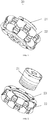
FIG. 1 is a schematic view of a caster module according to an embodiment of the present application; -
FIG. 2 is an exploded view of the caster module according to an embodiment of the present application; -
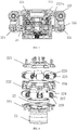
FIG. 3 is a sectional view of the caster module according to an embodiment of the present application; -
FIG. 4 is another exploded view of the caster module according to an embodiment of the present application; -
FIG. 5 is a schematic view of an inner-side roller in the caster module according to an embodiment of the present application; -
FIG. 6 is a schematic view of an outer-side roller in the caster module according to an embodiment of the present application; -
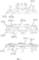
FIG. 7 is an exploded view of an omni wheel in the caster module according to an embodiment of the present application; -
FIG. 8 is a schematic view of an inner-side hub and the omni wheel in the caster module according to an embodiment of the present application; -
FIG. 9 is a schematic view of an omni wheel in the caster module according to an embodiment of the present application; and -
FIG. 10 is a schematic view of an effector according to an embodiment of the present application. - Reference numerals and denotations thereof:
-
Caster module 20; -
Effector 21; - Omni
wheel 22; - First bearing 23;
- Inner-
side hub 221; - Omni wheel
primary structure 222; - Outer-
side hub 223; - Inner-
side roller 224; - Outer-
side roller 225; - Second bearing 226;
- Third bearing 227;
-
Outer shaft pin 228; -
Inner shaft pin 229; - Inner through
hole 2241; - Outer through
hole 2251; - Omni wheel
primary structure body 2221; - First
outer boss 2222; - First
inner boss 2223; - Shaft
groove 2221a; - First
outer groove 2222a; - First
inner groove 2223a; - Inner-
side hub body 2211; - Second
inner boss 2212; - Connecting through
hole 2211a; - Second
inner groove 2212a; -
Inner rotation groove 221a; - Second
outer boss 2232; - Outer-
side hub body 2231; - Second
outer groove 2232a; -
Outer rotation groove 223a; -
Inner gasket 2210; -
Outer gasket 220; -
Flange 221. - The embodiments containing the technical solutions of the present application are described in detail with reference to the accompanying drawings. The embodiments hereinafter are only used to clearly describe the technical solutions of the present application. Therefore, these embodiments are only used as examples, but are not intended to limit the protection scope of the present application.
- It should be noted that unless otherwise specified, the technical terms and scientific terms used in the present application shall express general meanings that may be understood by a person skilled in the art.
- In the description of some embodiments of the present invention, it should be understood that the terms "central", "longitudinal", "transversal", "length", "width", "thickness", "upper", "lower", "front", "rear", "left", "right", "vertical", "horizontal", "top", "bottom", "inner", "outer", "clockwise", "counterclockwise", "axial", "radial", "circumferential" and the like indicate orientations and position relationships which are based on the illustrations in the accompanying drawings, and these terms are merely for ease and brevity of the description, instead of indicating or implying that the devices or elements shall have a particular orientation and shall be structured and operated based on the particular orientation. Accordingly, these terms shall not be construed as limiting the present invention.
- In addition, terms of "first", "second" are only used for description, but shall not be understood as indication or implication of relative importance or implicit indication of the number of the specific technical features. In the description of the present application, the term "more" or "a plurality of' signifies at least two, unless otherwise specified.
- In the description of the present application, it should be noted that unless otherwise specified and defined, the terms "mounted", "coupled", "connected" and "fixed" and derivative forms thereof shall be understood in a broad sense, which, for example, may be understood as fixed connection, detachable connection or integral connection; may be understood as mechanical connection or electrical connection, or understood as direct connection, indirect connection via an intermediate medium, or communication between the interiors of two elements or interactions between two elements. Persons of ordinary skill in the art may understand the specific meanings of the above terms in the present disclosure according to the actual circumstances and contexts.
- In the present application, unless otherwise specified or defined, by defining that a first feature is disposed "above" or "below" or "beneath" a second feature, it may be meant that the first feature is in direct contact with the second feature, or the first feature is in indirect contact with the second feature via an intermediate medium. In addition, by defining that a first feature is disposed "over" or "above" a second feature, it may be meant that the first feature is rightly over the second feature or is obliquely above the second feature, or the horizontal height of the first feature is greater than that of the second feature. In addition, by defining that a first feature is disposed "under" or "blow, or "beneath" a second feature, it may be meant that the first feature is rightly under the second feature or is obliquely below the second feature, or the horizontal height of the first feature is less than that of the second feature.
- Referring to
FIG. 1 and FIG. 2 , thecaster module 20 includes aneffector 21, anomni wheel 22, and afirst bearing 23. Thefirst bearing 23 is fixed to theomni wheel 22. Theeffector 21 is at least partially inserted into theomni wheel 22, a case of theeffector 21 is sleeved onto thefirst bearing 23, and an output end of theeffector 21 is connected to theomni wheel 22. When theeffector 21 drives the output end thereof to rotate, theomni wheel 22 may also rotate relative to the case of theeffector 21, such that theomni wheel 22 is driven to rotate, and hence functions of movement and steering of thecaster module 20 are implemented. - With respect to the
omni wheel 22, as illustrated inFIG. 3 to FIG. 4 , theomni wheel 22 includes an inner-side hub 221, an omni wheelprimary structure 22, an outer-side hub 223, a plurality of inner-side rollers 224, a plurality of outer-side rollers 225, a plurality ofsecond bearings 226, a plurality ofthird bearings 227, a plurality of outer shaft pins 228, and a plurality of inner shaft pins 229. - With respect to the inner-
side roller 224 and theinner shaft pin 229, as illustrated inFIG. 5 , the inner-side roller 224 is provided with an inner throughhole 2241. Onethird bearing 227 is fixed to the inner throughhole 2241 of one inner-side roller 224. Oneinner shaft pin 229 is inserted into the inner throughhole 2241, and sleeved onto thethird bearing 227, such that the inner-side roller 224 may rotate about theinner shaft pin 229. - In some embodiments, each inner-
side roller 224 may be provided with at least twothird bearings 227. The twothird bearings 227 are disposed at two ends of the throughhole 2241 of the inner-side roller 224, and theinner shaft pin 229 is sleeved onto the twothird bearings 227, such that the inner-side roller 224 may rotate more stably with less oscillation. - With respect to the outer-
side roller 225 and theouter shaft pin 228, as illustrated inFIG. 6 , the outer-side roller 225 is provided with an outer throughhole 2251. Onesecond bearing 226 is fixed to the outer throughhole 2251 of one outer-side roller 225. Oneouter shaft pin 228 is inserted into the outer throughhole 2251, and sleeved onto thesecond bearing 226, such that the outer-side roller 225 may rotate about theouter shaft pin 228. - In some embodiments, each outer-
side roller 225 may be provided with at least twosecond bearings 226. The twosecond bearings 226 are disposed at two ends of the outer throughhole 2251 of the outer-side roller 225, and theouter shaft pin 228 is sleeved onto the twosecond bearings 227, such that the outer-side roller 225 may rotate more stably with less oscillation. - With respect to the omni wheel
primary structure 222, as illustrated inFIG. 7 to FIG. 9 , the omni wheelprimary structure 222 includes an omni wheelprimary structure body 2221 and a plurality ofouter bosses 2222 and firstinner bosses 2223 that are defined by extending from the omni wheelprimary structure body 2221. The omni wheelprimary structure 2221 is provided with anshaft groove 2221a, wherein theshaft groove 2221a is provided with an edge. An outer ring of thefirst bearing 23 is in an interference fit to theshaft groove 2221a, and abuts against the edge of theshaft groove 2221a, such that thefirst bearing 23 is fixed to theshaft groove 2221a. The plurality of firstinner bosses 2223 are disposed around the omni wheelprimary structure body 2221, and a firstinner groove 2223a is defined between two adjacent firstinner bosses 2223. The plurality of firstouter bosses 2222 are disposed around the omni wheelprimary structure body 2221, and a firstouter groove 2222a is defined between two adjacent firstouter bosses 2222. - It may be understood that in some other embodiments, the
first bearing 23 may be connected to theshaft groove 2221a in other fashions other than the above described fashion. For example, thefirst bearing 23 may be connected to theshaft groove 2221a by key connection or pin connection. - With respect to the inner-
side hub 221, as illustrated inFIG. 7 to FIG. 9 , the inner-side hub 221 includes an inner-side hub body 2211 and a plurality of secondinner bosses 2212 that are defined by extending from the inner-side hub body 2211. The inner-side hub body 2211 is provided with a connecting throughhole 2211a. The plurality of secondinner bosses 2212 are disposed around the inner-side hub body 2211, and a secondinner groove 2212a is defined between two adjacent secondinner bosses 2212. The number of firstinner bosses 2223 is the same as the number of secondinner bosses 2212, and one firstinner boss 2223 is threaded to one secondinner boss 2212, such that the inner-side hub 221 is connected to the omni wheelprimary structure 222. In addition, when the firstinner boss 2223 is threaded to the secondinner boss 2212, the connecting throughhole 2211a is in communication with theshaft groove 2221a, and one firstinner groove 2223a is in communication with one secondinner groove 2212a, such that aninner rotation groove 221a is collaboratively defined. Oneinner shaft pin 229 is disposed in oneinner rotation groove 221a, and two ends of theinner shaft pin 229 are fixed to two opposing side walls of theinner rotation groove 221a, such that one inner-side roller 224 is rotatably connected to oneinner rotation groove 221a. - It may be understood that the inner-
side hub 221 may be connected to the omni wheelprimary structure 222 in other fashions, for example, welding connection, snap-fitting connection, or the like, other than the above described fashion. In addition, the inner-side hub 221 and the omni wheelprimary structure 222 may collaboratively define theinner rotation groove 221a in other fashions other than the above described fashion, and the inner-side roller 224 may be rotatably connected to theinner rotation groove 221 in other fashions other than the above described fashion, which are not described herein any further. - With respect to the outer-
side hub 223, as illustrated inFIG. 7 to FIG. 9 , the outer-side hub 223 includes an outer-side hub body 2231 and a plurality of secondouter bosses 2232 that are defined by extending from the outer-side hub body 2231. The plurality of secondouter bosses 2232 are disposed around the outer-side hub body 2231, and a secondouter groove 2232a is defined by two adjacentouter bosses 2232. The number of firstouter bosses 2222 is the same as the number of secondouter bosses 2232, and one firstouter boss 2222 is threaded to one secondouter boss 2232, such that the outer-side hub 223 is connected to the omni wheelprimary structure 222. In addition, when the firstouter boss 2222 is threaded to the secondouter boss 2232, one firstouter groove 2222a is in communication with one secondouter groove 2232a, such that anouter rotation groove 223a is collaboratively defined. Oneouter shaft pin 228 is disposed in oneouter rotation groove 223a, and two ends of theouter shaft pin 228 are fixed to two opposing side walls of theouter rotation groove 223a, such that one outer-side roller 225 is rotatably connected to oneouter rotation groove 223a. - It may be understood that the outer-
side hub 223 may be connected to the omni wheelprimary structure 222 in other fashions, for example, welding connection, snap-fitting connection, or the like, other than the above described fashion. The inner-side hub 221 and the omni wheelprimary structure 222 may collaboratively define theinner rotation groove 221a in other fashions other than the above described fashion, and the inner-side roller 224 may be rotatably connected to theinner rotation groove 221 in other fashions other than the above described fashion, which are not described herein any further. - In some embodiments, as illustrated in
FIG. 8 and FIG. 9 , theomni wheel 22 may further include aninner gasket 2210 and anouter gasket 220. Theinner gasket 2210 is sleeved onto theinner shaft pin 229, and theinner gasket 2210 is disposed between thethird bearing 227 and the side wall of theinner rotation groove 221a, and configured to stop thethird bearing 227 to prevent thethird bearing 227 from detaching from theinner shaft pin 229. Theouter gasket 220 is sleeved onto theouter shaft pin 228, and theouter gasket 220 is disposed between thesecond bearing 226 and the side wall of theouter rotation groove 223a, and configured to stop thesecond bearing 226 to prevent thesecond bearing 226 from detaching from theouter shaft pin 228. - With respect to the
effector 21, as illustrated inFIG. 10 andFIG. 3 , theeffector 21 is inserted into theshaft groove 2221a from the connecting throughhole 2211a of the inner-side hub 221, and sleeved onto thefirst bearing 23 in theshaft groove 2221a, and the output end of theeffector 21 is connected to a surface of the outer-side hub 223 facing towards theshaft groove 2221a. When the output end of theeffector 21 rotates, the output end of theeffector 21 drives theomni wheel 22 to rotate. In some embodiments, theeffector 21 may be an outer rotor effector, and the output end of theeffector 21 may be aflange 211, such that theeffector 21 outputs a greater torque. - It may be understood that the
flange 211 may also be connected to the outer-side hub 223 by flange threading or welding or the like. - In some embodiments, the caster module may not include the
first bearing 23, a gap is defined between the omni wheelprimary structure 222 and the case of theeffector 21, and the omni wheelprimary structure 222 may be rotatable relative to the case of theeffector 21. - For readers' better understanding of the inventive concept of the present application, an assembling process of the
caster module 20 is described as follows: fixing the inner ring of thefirst bearing 23 to the case of theeffector 21; threading theeffector 21 to the outer-side hub 223; fixing theouter shaft pin 228 to the inner ring of thesecond bearing 226; fixing the outer ring of thesecond bearing 226 to the outer throughhole 2251 of the outer-side roller 225; sleeving theouter gasket 220 onto theouter shaft pin 228; threading the omni wheelprimary structure 222 to the outer-side hub 223; fixing theinner shaft pin 229 to the inner ring of thethird bearing 227; fixing the outer ring of thethird bearing 227 to the inner throughhole 2241 of the inner-side roller 224; sleeving thegasket 2210 onto theinner shaft pin 229; and threading the omni wheelprimary structure 222 to the inner-side hub 221. - It may be understood that the assembling fashion of the
caster module 20 is not limited to the above described assembling process. Other assembling fashions may also apply to the caster module, which are not described herein any further. - For readers' better understanding of the inventive concept of the present application, hereinafter, a movement process of the
caster module 20 is described as follows: - First, the
effector 21 drives theflange 211 to rotate, theflange 211 hence drives the outer-side hub 223 to rotate, the outer-side hub 223 then drives the omni wheelprimary structure 222 to rotate, and finally the omni wheelprimary structure 222 drives the inner-side hub 221 to rotate. - In the embodiments of the present application, the
effector 21 is received in theshaft groove 2221a of theomni wheel 22, and the case of theeffector 21 is rotatable relative to the inner wall of theshaft groove 2221a; in the meantime, theflange 211 of theeffector 21 is fixed to theomni wheel 22, and when theeffector 21 drives theflange 211 to rotate, theomni wheel 22 may rotate relative to theeffector 21, such that theeffector 21 is integrated in theomni wheel 22. As compared with the configuration where theeffector 21 is separated from theomni wheel 22, and theeffector 21 and theomni wheel 22 both occupy a space, thecaster module 20 according to the embodiments occupies a smaller space, and achieves a higher integration degree, such that the robot becomes lighter. - An embodiment of the present application further provides a robot. The robot includes a caster module. The caster module has the same structure and functionality as the caster module according to the above embodiment. For details of the structure and functionality of the caster module, reference may be made to the above embodiment, which is not described herein any further.
- It should be finally noted that the above-described embodiments are merely for illustration of the present application, but are not intended to limit the present application. Although the present invention is described in detail with reference to these embodiments, a person skilled in the art may also make various modifications to the technical solutions disclosed in the embodiments, or make equivalent replacements to a part of or all technical features contained therein. Such modifications or replacement, made without departing from the principles of the present application, shall fall within the scope defined by the claims and the specification of the present application. Especially, various technical features mentioned in various embodiments may be combined in any fashion as long as there is no structural conflict. The present application is not limited to the specific embodiments described herein in this specification, but also includes all the technical solutions falling within the scope subject to the appended claims.
Claims (10)
- A caster module (20), comprising:an omni wheel (22), provided with an shaft groove (2221a); andan effector (21), received in the shaft groove (2221a), a case of the effector (21) being rotatable relative to an inner wall of the shaft groove (2221a), and an output end of the effector (21) being connected to the omni wheel (22) and configured to drive the omni wheel (22) to rotate.
- The caster module (20) according to claim 1, further comprising a first bearing (23), the first bearing (23) being disposed in the shaft groove (2221a), an outer ring of the first bearing (23) being fixed to the inner wall of the shaft groove (2221a), the case of the effector (21) being sleeved onto the first bearing (23), and the case of the effector (21) being fixed to an inner ring of the first bearing (23).
- The caster module (20) according to claim 1, wherein the omni wheel (22) comprises an inner-side hub (221), an omni wheel primary structure (222), an outer-side hub (223), an inner-side roller (224), and an outer-side roller (225); wherein
the shaft groove (2221a) is disposed on the omni wheel primary structure (222), the inner-side hub (221) and the outer-side hub (223) are both connected to the omni wheel primary structure (222), the inner-side hub (221) and the outer-side hub (223) are respectively disposed at two ends of the shaft groove (2221a), the inner-side hub (221) and the omni wheel primary structure (222) collaboratively define an inner rotation groove (221a), the inner-side roller (224) being rotatably connected to the inner rotation groove (221a), and the outer-side hub (223) and the omni wheel primary structure (222) collaboratively define an outer rotation groove (223a), the outer-side roller (225) being rotatably being connected to the outer rotation groove (223a); and
the inner-side hub (221) is provided with a connecting through hole (2211a) in communication with the shaft groove (2221a), the effector (21) is inserted into the shaft groove (2221a) by the connecting through hole (2211a), and the output end of the effector (21) is connected to a surface of the outer-side hub (223) facing towards the shaft groove (2221a). - The caster module (20) according to claim 3, wherein the omni wheel (22) further comprises a second bearing (226) and an outer shaft pin (228); wherein
the outer-side roller (225) is provided with an outer through hole (2251), the second bearing (226) is fixed to the outer through hole (2251); the outer shaft pin (228) is inserted into the outer through hole (2251) and sleeved onto the second bearing (226), and two ends of the outer shaft pin (228) are respectively fixed to two opposing side walls of the outer rotation groove (223a). - The caster module (20) according to claim 4, wherein the omni wheel (22) further comprises an outer gasket (220), the outer gasket (220) being sleeved onto one end of the outer shaft pin (228), and the outer gasket (220) being disposed between the second bearing (226) and a side wall of the outer rotation groove (223a).
- The caster module (20) according to claim 3, wherein the omni wheel (22) further comprises a third bearing (227) and an inner shaft pin (229); wherein
the inner-side roller (224) is provided with an inner through hole (2241), the third bearing (227) is fixed to the inner through hole (2241); the inner shaft pin (229) is inserted into the inner through hole (2241) and sleeved onto the third bearing (227), and two ends of the outer shaft pin (228) are respectively fixed to two opposing side walls of the outer rotation groove (223a). - The caster module (20) according to claim 6, wherein the omni wheel (22) further comprises an inner gasket (2210), the inner gasket (2210) being sleeved onto one end of the inner shaft pin (229), and the inner gasket (2210) being disposed between the third bearing (227) and a side wall of the inner rotation groove (221a).
- The caster module (20) according to claim 3, wherein the inner-side hub (221) is threaded to the omni wheel primary structure (222), and the outer-side hub (223) is threaded to the omni wheel primary structure (222).
- The module according to any one of claims 1 to 8, wherein the output end of the effector (21) is a flange.
- A robot, comprising the caster module (20) as defined in any one of claims 1 to 9.
Applications Claiming Priority (1)
| Application Number | Priority Date | Filing Date | Title |
|---|---|---|---|
| CN201920266830.7U CN209755188U (en) | 2019-03-01 | 2019-03-01 | A wheel caster module and robot |
Publications (2)
| Publication Number | Publication Date |
|---|---|
| EP3702173A1 true EP3702173A1 (en) | 2020-09-02 |
| EP3702173B1 EP3702173B1 (en) | 2021-10-27 |
Family
ID=68753363
Family Applications (1)
| Application Number | Title | Priority Date | Filing Date |
|---|---|---|---|
| EP20159686.3A Active EP3702173B1 (en) | 2019-03-01 | 2020-02-27 | Caster module and robot |
Country Status (4)
| Country | Link |
|---|---|
| US (1) | US11498202B2 (en) |
| EP (1) | EP3702173B1 (en) |
| JP (1) | JP6963153B2 (en) |
| CN (1) | CN209755188U (en) |
Families Citing this family (8)
| Publication number | Priority date | Publication date | Assignee | Title |
|---|---|---|---|---|
| EP3705309A1 (en) * | 2019-03-05 | 2020-09-09 | Ecole Polytechnique Federale De Lausanne (EPFL) EPFL-TTO | Motor-wheel for an omni-directional mechanism and vehicle using the same |
| JP1677029S (en) * | 2019-12-09 | 2021-01-18 | ||
| USD928680S1 (en) * | 2019-12-27 | 2021-08-24 | Rotacaster Wheel Pty Ltd. | Multiple directional wheel rim |
| JP7469918B2 (en) * | 2020-03-13 | 2024-04-17 | 住友重機械工業株式会社 | Drive unit |
| USD937336S1 (en) * | 2020-08-24 | 2021-11-30 | Beijing Keyi Technology Co., Ltd. | Snap robot module |
| USD937334S1 (en) * | 2020-08-24 | 2021-11-30 | Beijing Keyi Technology Co., Ltd. | Joint robot module |
| USD937335S1 (en) * | 2020-08-24 | 2021-11-30 | Beijing Keyi Technology Co., Ltd. | Brain robot module |
| USD942518S1 (en) * | 2020-08-24 | 2022-02-01 | Beijing Keyi Technology Co., Ltd. | Two-wheel car robot |
Citations (5)
| Publication number | Priority date | Publication date | Assignee | Title |
|---|---|---|---|---|
| US20120061156A1 (en) * | 2009-05-11 | 2012-03-15 | Honda Motor Co., Ltd. | Friction drive device and omni-directional vehicle using the same |
| US20150129327A1 (en) * | 2013-11-14 | 2015-05-14 | Honda Motor Co., Ltd. | Wheel, wheel device and inverted pendulum type vehicle |
| CN105730216A (en) * | 2016-01-12 | 2016-07-06 | 沈阳工业大学 | Integrated universal wheel and control method thereof |
| CN107105950A (en) * | 2015-01-20 | 2017-08-29 | 欧罗菲利特斯控股公司 | Vacuum cleaner robot |
| US20180361784A1 (en) * | 2017-06-01 | 2018-12-20 | Trumpf Medizin Systeme Gmbh + Co. Kg | Running wheel |
Family Cites Families (8)
| Publication number | Priority date | Publication date | Assignee | Title |
|---|---|---|---|---|
| US6315109B1 (en) * | 1998-04-30 | 2001-11-13 | Stewart & Stephenson Services, Inc. | Split roller wheel and method of assembly |
| JP4003082B2 (en) * | 2005-07-15 | 2007-11-07 | 株式会社相愛 | Omni-directional wheel and omni-directional moving device |
| DE102011053903A1 (en) * | 2011-09-23 | 2013-03-28 | Zdenek Spindler | Mecanumrad as well as Mecanumradfahrzeug |
| CN105751815A (en) * | 2016-04-29 | 2016-07-13 | 广东科杰达智能电器有限公司 | Omni wheel of floor sweeping robot |
| JP2018134917A (en) | 2017-02-20 | 2018-08-30 | ナブテスコ株式会社 | Drive device for carriage bogie |
| JP3217560U (en) * | 2017-10-30 | 2018-08-16 | 深▲せん▼市工匠社科技有限公司 | Omni-directional moving chassis |
| US20190126675A1 (en) * | 2017-10-30 | 2019-05-02 | GJS CO.,Ltd | Small double-row omni-directional wheel |
| CN111347823A (en) * | 2018-12-20 | 2020-06-30 | 沈阳新松机器人自动化股份有限公司 | A servo omnidirectional wheel |
-
2019
- 2019-03-01 CN CN201920266830.7U patent/CN209755188U/en active Active
-
2020
- 2020-02-27 JP JP2020032061A patent/JP6963153B2/en active Active
- 2020-02-27 EP EP20159686.3A patent/EP3702173B1/en active Active
- 2020-03-02 US US16/806,740 patent/US11498202B2/en active Active
Patent Citations (5)
| Publication number | Priority date | Publication date | Assignee | Title |
|---|---|---|---|---|
| US20120061156A1 (en) * | 2009-05-11 | 2012-03-15 | Honda Motor Co., Ltd. | Friction drive device and omni-directional vehicle using the same |
| US20150129327A1 (en) * | 2013-11-14 | 2015-05-14 | Honda Motor Co., Ltd. | Wheel, wheel device and inverted pendulum type vehicle |
| CN107105950A (en) * | 2015-01-20 | 2017-08-29 | 欧罗菲利特斯控股公司 | Vacuum cleaner robot |
| CN105730216A (en) * | 2016-01-12 | 2016-07-06 | 沈阳工业大学 | Integrated universal wheel and control method thereof |
| US20180361784A1 (en) * | 2017-06-01 | 2018-12-20 | Trumpf Medizin Systeme Gmbh + Co. Kg | Running wheel |
Also Published As
| Publication number | Publication date |
|---|---|
| CN209755188U (en) | 2019-12-10 |
| EP3702173B1 (en) | 2021-10-27 |
| US20200276697A1 (en) | 2020-09-03 |
| JP2020138729A (en) | 2020-09-03 |
| JP6963153B2 (en) | 2021-11-05 |
| US11498202B2 (en) | 2022-11-15 |
Similar Documents
| Publication | Publication Date | Title |
|---|---|---|
| EP3702173A1 (en) | Caster module and robot | |
| US8011735B2 (en) | Wheel for omni-directional vehicle | |
| CN104055305B (en) | For the conical bearing of the wheel assembly of luggage case | |
| WO2021054938A1 (en) | Bearing support for parallel electric axle gear assembly | |
| EP3702112B1 (en) | Robot head and neck assembly, and robot | |
| US20080041747A1 (en) | Thrust-out type container for a rod-like article such as a lipstick | |
| CN112744312B (en) | Bionic robot and leg structure thereof | |
| US11813738B2 (en) | Robot waist skeleton and robot | |
| KR101712834B1 (en) | Carriage Assembly of Mobile Rack | |
| US20230331038A1 (en) | Wheel and Mobility Including the Same | |
| JPH10169649A (en) | Divided aligning rolling bearing device | |
| US20070076997A1 (en) | Crossed roller bearing | |
| KR20200029565A (en) | Thrust bearing cage with shortened flange | |
| JP2007196867A (en) | Omnidirectional traveling wheel and truck | |
| KR20190067318A (en) | Spherical ball type omni wheel | |
| JP6217738B2 (en) | Worm gear slewing bearing | |
| JP7394127B2 (en) | winding machine | |
| CN218144914U (en) | Rolling shaft and adhesive tape rolling equipment | |
| CN118008947A (en) | Ball bearing and computer tomography frame | |
| KR102790666B1 (en) | Caster with smooth reverse rotation | |
| CN221585601U (en) | Humanoid robot | |
| KR20130067625A (en) | Ball caster | |
| CN111891217A (en) | Suspension structure of vehicle and vehicle | |
| JP2010007705A (en) | Sliding type tripod constant velocity joint | |
| JP5083067B2 (en) | Sliding tripod type constant velocity joint |
Legal Events
| Date | Code | Title | Description |
|---|---|---|---|
| PUAI | Public reference made under article 153(3) epc to a published international application that has entered the european phase |
Free format text: ORIGINAL CODE: 0009012 |
|
| STAA | Information on the status of an ep patent application or granted ep patent |
Free format text: STATUS: THE APPLICATION HAS BEEN PUBLISHED |
|
| AK | Designated contracting states |
Kind code of ref document: A1 Designated state(s): AL AT BE BG CH CY CZ DE DK EE ES FI FR GB GR HR HU IE IS IT LI LT LU LV MC MK MT NL NO PL PT RO RS SE SI SK SM TR |
|
| AX | Request for extension of the european patent |
Extension state: BA ME |
|
| STAA | Information on the status of an ep patent application or granted ep patent |
Free format text: STATUS: REQUEST FOR EXAMINATION WAS MADE |
|
| 17P | Request for examination filed |
Effective date: 20210301 |
|
| RBV | Designated contracting states (corrected) |
Designated state(s): AL AT BE BG CH CY CZ DE DK EE ES FI FR GB GR HR HU IE IS IT LI LT LU LV MC MK MT NL NO PL PT RO RS SE SI SK SM TR |
|
| GRAP | Despatch of communication of intention to grant a patent |
Free format text: ORIGINAL CODE: EPIDOSNIGR1 |
|
| STAA | Information on the status of an ep patent application or granted ep patent |
Free format text: STATUS: GRANT OF PATENT IS INTENDED |
|
| RAP1 | Party data changed (applicant data changed or rights of an application transferred) |
Owner name: CLOUDMINDS (SHENZHEN) HOLDINGS CO., LTD. Owner name: CLOUDMINDS (BEIJING) TECHNOLOGIES CO., LTD. |
|
| INTG | Intention to grant announced |
Effective date: 20210722 |
|
| GRAS | Grant fee paid |
Free format text: ORIGINAL CODE: EPIDOSNIGR3 |
|
| GRAA | (expected) grant |
Free format text: ORIGINAL CODE: 0009210 |
|
| STAA | Information on the status of an ep patent application or granted ep patent |
Free format text: STATUS: THE PATENT HAS BEEN GRANTED |
|
| RAP1 | Party data changed (applicant data changed or rights of an application transferred) |
Owner name: CLOUDMINDS ROBOTICS CO., LTD. Owner name: CLOUDMINDS (BEIJING) TECHNOLOGIES CO., LTD. |
|
| AK | Designated contracting states |
Kind code of ref document: B1 Designated state(s): AL AT BE BG CH CY CZ DE DK EE ES FI FR GB GR HR HU IE IS IT LI LT LU LV MC MK MT NL NO PL PT RO RS SE SI SK SM TR |
|
| REG | Reference to a national code |
Ref country code: GB Ref legal event code: FG4D |
|
| REG | Reference to a national code |
Ref country code: CH Ref legal event code: EP |
|
| REG | Reference to a national code |
Ref country code: AT Ref legal event code: REF Ref document number: 1441467 Country of ref document: AT Kind code of ref document: T Effective date: 20211115 |
|
| REG | Reference to a national code |
Ref country code: DE Ref legal event code: R096 Ref document number: 602020000814 Country of ref document: DE |
|
| REG | Reference to a national code |
Ref country code: IE Ref legal event code: FG4D |
|
| REG | Reference to a national code |
Ref country code: LT Ref legal event code: MG9D |
|
| REG | Reference to a national code |
Ref country code: NL Ref legal event code: MP Effective date: 20211027 |
|
| REG | Reference to a national code |
Ref country code: AT Ref legal event code: MK05 Ref document number: 1441467 Country of ref document: AT Kind code of ref document: T Effective date: 20211027 |
|
| PG25 | Lapsed in a contracting state [announced via postgrant information from national office to epo] |
Ref country code: RS Free format text: LAPSE BECAUSE OF FAILURE TO SUBMIT A TRANSLATION OF THE DESCRIPTION OR TO PAY THE FEE WITHIN THE PRESCRIBED TIME-LIMIT Effective date: 20211027 Ref country code: LT Free format text: LAPSE BECAUSE OF FAILURE TO SUBMIT A TRANSLATION OF THE DESCRIPTION OR TO PAY THE FEE WITHIN THE PRESCRIBED TIME-LIMIT Effective date: 20211027 Ref country code: FI Free format text: LAPSE BECAUSE OF FAILURE TO SUBMIT A TRANSLATION OF THE DESCRIPTION OR TO PAY THE FEE WITHIN THE PRESCRIBED TIME-LIMIT Effective date: 20211027 Ref country code: BG Free format text: LAPSE BECAUSE OF FAILURE TO SUBMIT A TRANSLATION OF THE DESCRIPTION OR TO PAY THE FEE WITHIN THE PRESCRIBED TIME-LIMIT Effective date: 20220127 Ref country code: AT Free format text: LAPSE BECAUSE OF FAILURE TO SUBMIT A TRANSLATION OF THE DESCRIPTION OR TO PAY THE FEE WITHIN THE PRESCRIBED TIME-LIMIT Effective date: 20211027 |
|
| PG25 | Lapsed in a contracting state [announced via postgrant information from national office to epo] |
Ref country code: IS Free format text: LAPSE BECAUSE OF FAILURE TO SUBMIT A TRANSLATION OF THE DESCRIPTION OR TO PAY THE FEE WITHIN THE PRESCRIBED TIME-LIMIT Effective date: 20220227 Ref country code: SE Free format text: LAPSE BECAUSE OF FAILURE TO SUBMIT A TRANSLATION OF THE DESCRIPTION OR TO PAY THE FEE WITHIN THE PRESCRIBED TIME-LIMIT Effective date: 20211027 Ref country code: PT Free format text: LAPSE BECAUSE OF FAILURE TO SUBMIT A TRANSLATION OF THE DESCRIPTION OR TO PAY THE FEE WITHIN THE PRESCRIBED TIME-LIMIT Effective date: 20220228 Ref country code: PL Free format text: LAPSE BECAUSE OF FAILURE TO SUBMIT A TRANSLATION OF THE DESCRIPTION OR TO PAY THE FEE WITHIN THE PRESCRIBED TIME-LIMIT Effective date: 20211027 Ref country code: NO Free format text: LAPSE BECAUSE OF FAILURE TO SUBMIT A TRANSLATION OF THE DESCRIPTION OR TO PAY THE FEE WITHIN THE PRESCRIBED TIME-LIMIT Effective date: 20220127 Ref country code: NL Free format text: LAPSE BECAUSE OF FAILURE TO SUBMIT A TRANSLATION OF THE DESCRIPTION OR TO PAY THE FEE WITHIN THE PRESCRIBED TIME-LIMIT Effective date: 20211027 Ref country code: LV Free format text: LAPSE BECAUSE OF FAILURE TO SUBMIT A TRANSLATION OF THE DESCRIPTION OR TO PAY THE FEE WITHIN THE PRESCRIBED TIME-LIMIT Effective date: 20211027 Ref country code: HR Free format text: LAPSE BECAUSE OF FAILURE TO SUBMIT A TRANSLATION OF THE DESCRIPTION OR TO PAY THE FEE WITHIN THE PRESCRIBED TIME-LIMIT Effective date: 20211027 Ref country code: GR Free format text: LAPSE BECAUSE OF FAILURE TO SUBMIT A TRANSLATION OF THE DESCRIPTION OR TO PAY THE FEE WITHIN THE PRESCRIBED TIME-LIMIT Effective date: 20220128 Ref country code: ES Free format text: LAPSE BECAUSE OF FAILURE TO SUBMIT A TRANSLATION OF THE DESCRIPTION OR TO PAY THE FEE WITHIN THE PRESCRIBED TIME-LIMIT Effective date: 20211027 |
|
| REG | Reference to a national code |
Ref country code: DE Ref legal event code: R097 Ref document number: 602020000814 Country of ref document: DE |
|
| PG25 | Lapsed in a contracting state [announced via postgrant information from national office to epo] |
Ref country code: SM Free format text: LAPSE BECAUSE OF FAILURE TO SUBMIT A TRANSLATION OF THE DESCRIPTION OR TO PAY THE FEE WITHIN THE PRESCRIBED TIME-LIMIT Effective date: 20211027 Ref country code: SK Free format text: LAPSE BECAUSE OF FAILURE TO SUBMIT A TRANSLATION OF THE DESCRIPTION OR TO PAY THE FEE WITHIN THE PRESCRIBED TIME-LIMIT Effective date: 20211027 Ref country code: RO Free format text: LAPSE BECAUSE OF FAILURE TO SUBMIT A TRANSLATION OF THE DESCRIPTION OR TO PAY THE FEE WITHIN THE PRESCRIBED TIME-LIMIT Effective date: 20211027 Ref country code: EE Free format text: LAPSE BECAUSE OF FAILURE TO SUBMIT A TRANSLATION OF THE DESCRIPTION OR TO PAY THE FEE WITHIN THE PRESCRIBED TIME-LIMIT Effective date: 20211027 Ref country code: DK Free format text: LAPSE BECAUSE OF FAILURE TO SUBMIT A TRANSLATION OF THE DESCRIPTION OR TO PAY THE FEE WITHIN THE PRESCRIBED TIME-LIMIT Effective date: 20211027 Ref country code: CZ Free format text: LAPSE BECAUSE OF FAILURE TO SUBMIT A TRANSLATION OF THE DESCRIPTION OR TO PAY THE FEE WITHIN THE PRESCRIBED TIME-LIMIT Effective date: 20211027 |
|
| PLBE | No opposition filed within time limit |
Free format text: ORIGINAL CODE: 0009261 |
|
| STAA | Information on the status of an ep patent application or granted ep patent |
Free format text: STATUS: NO OPPOSITION FILED WITHIN TIME LIMIT |
|
| PG25 | Lapsed in a contracting state [announced via postgrant information from national office to epo] |
Ref country code: MC Free format text: LAPSE BECAUSE OF FAILURE TO SUBMIT A TRANSLATION OF THE DESCRIPTION OR TO PAY THE FEE WITHIN THE PRESCRIBED TIME-LIMIT Effective date: 20211027 |
|
| 26N | No opposition filed |
Effective date: 20220728 |
|
| REG | Reference to a national code |
Ref country code: BE Ref legal event code: MM Effective date: 20220228 |
|
| PG25 | Lapsed in a contracting state [announced via postgrant information from national office to epo] |
Ref country code: LU Free format text: LAPSE BECAUSE OF NON-PAYMENT OF DUE FEES Effective date: 20220227 Ref country code: AL Free format text: LAPSE BECAUSE OF FAILURE TO SUBMIT A TRANSLATION OF THE DESCRIPTION OR TO PAY THE FEE WITHIN THE PRESCRIBED TIME-LIMIT Effective date: 20211027 |
|
| PG25 | Lapsed in a contracting state [announced via postgrant information from national office to epo] |
Ref country code: SI Free format text: LAPSE BECAUSE OF FAILURE TO SUBMIT A TRANSLATION OF THE DESCRIPTION OR TO PAY THE FEE WITHIN THE PRESCRIBED TIME-LIMIT Effective date: 20211027 |
|
| PG25 | Lapsed in a contracting state [announced via postgrant information from national office to epo] |
Ref country code: IE Free format text: LAPSE BECAUSE OF NON-PAYMENT OF DUE FEES Effective date: 20220227 |
|
| PG25 | Lapsed in a contracting state [announced via postgrant information from national office to epo] |
Ref country code: BE Free format text: LAPSE BECAUSE OF NON-PAYMENT OF DUE FEES Effective date: 20220228 |
|
| PG25 | Lapsed in a contracting state [announced via postgrant information from national office to epo] |
Ref country code: IT Free format text: LAPSE BECAUSE OF FAILURE TO SUBMIT A TRANSLATION OF THE DESCRIPTION OR TO PAY THE FEE WITHIN THE PRESCRIBED TIME-LIMIT Effective date: 20211027 |
|
| REG | Reference to a national code |
Ref country code: CH Ref legal event code: PL |
|
| PG25 | Lapsed in a contracting state [announced via postgrant information from national office to epo] |
Ref country code: LI Free format text: LAPSE BECAUSE OF NON-PAYMENT OF DUE FEES Effective date: 20230228 Ref country code: CH Free format text: LAPSE BECAUSE OF NON-PAYMENT OF DUE FEES Effective date: 20230228 |
|
| PG25 | Lapsed in a contracting state [announced via postgrant information from national office to epo] |
Ref country code: MK Free format text: LAPSE BECAUSE OF FAILURE TO SUBMIT A TRANSLATION OF THE DESCRIPTION OR TO PAY THE FEE WITHIN THE PRESCRIBED TIME-LIMIT Effective date: 20211027 Ref country code: CY Free format text: LAPSE BECAUSE OF FAILURE TO SUBMIT A TRANSLATION OF THE DESCRIPTION OR TO PAY THE FEE WITHIN THE PRESCRIBED TIME-LIMIT Effective date: 20211027 |
|
| PG25 | Lapsed in a contracting state [announced via postgrant information from national office to epo] |
Ref country code: HU Free format text: LAPSE BECAUSE OF FAILURE TO SUBMIT A TRANSLATION OF THE DESCRIPTION OR TO PAY THE FEE WITHIN THE PRESCRIBED TIME-LIMIT; INVALID AB INITIO Effective date: 20200227 |
|
| PG25 | Lapsed in a contracting state [announced via postgrant information from national office to epo] |
Ref country code: TR Free format text: LAPSE BECAUSE OF FAILURE TO SUBMIT A TRANSLATION OF THE DESCRIPTION OR TO PAY THE FEE WITHIN THE PRESCRIBED TIME-LIMIT Effective date: 20211027 |
|
| PG25 | Lapsed in a contracting state [announced via postgrant information from national office to epo] |
Ref country code: MT Free format text: LAPSE BECAUSE OF FAILURE TO SUBMIT A TRANSLATION OF THE DESCRIPTION OR TO PAY THE FEE WITHIN THE PRESCRIBED TIME-LIMIT Effective date: 20211027 |
|
| PGFP | Annual fee paid to national office [announced via postgrant information from national office to epo] |
Ref country code: GB Payment date: 20260219 Year of fee payment: 7 |
|
| PGFP | Annual fee paid to national office [announced via postgrant information from national office to epo] |
Ref country code: DE Payment date: 20260206 Year of fee payment: 7 |
|
| PGFP | Annual fee paid to national office [announced via postgrant information from national office to epo] |
Ref country code: FR Payment date: 20260227 Year of fee payment: 7 |