EP3702138A1 - Method for producing composite material and composite material - Google Patents
Method for producing composite material and composite material Download PDFInfo
- Publication number
- EP3702138A1 EP3702138A1 EP18906587.3A EP18906587A EP3702138A1 EP 3702138 A1 EP3702138 A1 EP 3702138A1 EP 18906587 A EP18906587 A EP 18906587A EP 3702138 A1 EP3702138 A1 EP 3702138A1
- Authority
- EP
- European Patent Office
- Prior art keywords
- resin
- outer member
- composite material
- reinforcing fibers
- inner member
- Prior art date
- Legal status (The legal status is an assumption and is not a legal conclusion. Google has not performed a legal analysis and makes no representation as to the accuracy of the status listed.)
- Withdrawn
Links
Images




Classifications
-
- B—PERFORMING OPERATIONS; TRANSPORTING
- B29—WORKING OF PLASTICS; WORKING OF SUBSTANCES IN A PLASTIC STATE IN GENERAL
- B29C—SHAPING OR JOINING OF PLASTICS; SHAPING OF MATERIAL IN A PLASTIC STATE, NOT OTHERWISE PROVIDED FOR; AFTER-TREATMENT OF THE SHAPED PRODUCTS, e.g. REPAIRING
- B29C70/00—Shaping composites, i.e. plastics material comprising reinforcements, fillers or preformed parts, e.g. inserts
- B29C70/04—Shaping composites, i.e. plastics material comprising reinforcements, fillers or preformed parts, e.g. inserts comprising reinforcements only, e.g. self-reinforcing plastics
- B29C70/06—Fibrous reinforcements only
- B29C70/08—Fibrous reinforcements only comprising combinations of different forms of fibrous reinforcements incorporated in matrix material, forming one or more layers, and with or without non-reinforced layers
-
- B—PERFORMING OPERATIONS; TRANSPORTING
- B29—WORKING OF PLASTICS; WORKING OF SUBSTANCES IN A PLASTIC STATE IN GENERAL
- B29C—SHAPING OR JOINING OF PLASTICS; SHAPING OF MATERIAL IN A PLASTIC STATE, NOT OTHERWISE PROVIDED FOR; AFTER-TREATMENT OF THE SHAPED PRODUCTS, e.g. REPAIRING
- B29C70/00—Shaping composites, i.e. plastics material comprising reinforcements, fillers or preformed parts, e.g. inserts
- B29C70/04—Shaping composites, i.e. plastics material comprising reinforcements, fillers or preformed parts, e.g. inserts comprising reinforcements only, e.g. self-reinforcing plastics
- B29C70/06—Fibrous reinforcements only
- B29C70/10—Fibrous reinforcements only characterised by the structure of fibrous reinforcements, e.g. hollow fibres
- B29C70/16—Fibrous reinforcements only characterised by the structure of fibrous reinforcements, e.g. hollow fibres using fibres of substantial or continuous length
- B29C70/22—Fibrous reinforcements only characterised by the structure of fibrous reinforcements, e.g. hollow fibres using fibres of substantial or continuous length oriented in at least two directions forming a two-dimensional [2D] structure
- B29C70/222—Fibrous reinforcements only characterised by the structure of fibrous reinforcements, e.g. hollow fibres using fibres of substantial or continuous length oriented in at least two directions forming a two-dimensional [2D] structure the structure being shaped to form a three dimensional configuration
-
- B—PERFORMING OPERATIONS; TRANSPORTING
- B29—WORKING OF PLASTICS; WORKING OF SUBSTANCES IN A PLASTIC STATE IN GENERAL
- B29C—SHAPING OR JOINING OF PLASTICS; SHAPING OF MATERIAL IN A PLASTIC STATE, NOT OTHERWISE PROVIDED FOR; AFTER-TREATMENT OF THE SHAPED PRODUCTS, e.g. REPAIRING
- B29C70/00—Shaping composites, i.e. plastics material comprising reinforcements, fillers or preformed parts, e.g. inserts
- B29C70/68—Shaping composites, i.e. plastics material comprising reinforcements, fillers or preformed parts, e.g. inserts by incorporating or moulding on preformed parts, e.g. inserts or layers, e.g. foam blocks
-
- B—PERFORMING OPERATIONS; TRANSPORTING
- B29—WORKING OF PLASTICS; WORKING OF SUBSTANCES IN A PLASTIC STATE IN GENERAL
- B29C—SHAPING OR JOINING OF PLASTICS; SHAPING OF MATERIAL IN A PLASTIC STATE, NOT OTHERWISE PROVIDED FOR; AFTER-TREATMENT OF THE SHAPED PRODUCTS, e.g. REPAIRING
- B29C70/00—Shaping composites, i.e. plastics material comprising reinforcements, fillers or preformed parts, e.g. inserts
- B29C70/68—Shaping composites, i.e. plastics material comprising reinforcements, fillers or preformed parts, e.g. inserts by incorporating or moulding on preformed parts, e.g. inserts or layers, e.g. foam blocks
- B29C70/86—Incorporated in coherent impregnated reinforcing layers, e.g. by winding
-
- B—PERFORMING OPERATIONS; TRANSPORTING
- B29—WORKING OF PLASTICS; WORKING OF SUBSTANCES IN A PLASTIC STATE IN GENERAL
- B29K—INDEXING SCHEME ASSOCIATED WITH SUBCLASSES B29B, B29C OR B29D, RELATING TO MOULDING MATERIALS OR TO MATERIALS FOR MOULDS, REINFORCEMENTS, FILLERS OR PREFORMED PARTS, e.g. INSERTS
- B29K2105/00—Condition, form or state of moulded material or of the material to be shaped
- B29K2105/06—Condition, form or state of moulded material or of the material to be shaped containing reinforcements, fillers or inserts
- B29K2105/08—Condition, form or state of moulded material or of the material to be shaped containing reinforcements, fillers or inserts of continuous length, e.g. cords, rovings, mats, fabrics, strands or yarns
- B29K2105/0809—Fabrics
- B29K2105/0845—Woven fabrics
-
- B—PERFORMING OPERATIONS; TRANSPORTING
- B29—WORKING OF PLASTICS; WORKING OF SUBSTANCES IN A PLASTIC STATE IN GENERAL
- B29L—INDEXING SCHEME ASSOCIATED WITH SUBCLASS B29C, RELATING TO PARTICULAR ARTICLES
- B29L2031/00—Other particular articles
- B29L2031/001—Profiled members, e.g. beams, sections
Definitions
- the present invention relates to a method for producing a composite material and a composite material.
- a composite material including a resin and reinforcing fibers is lighter than a metal material and further has higher specific strength and specific rigidity. Therefore, the composite material is used for various applications including a member of an aircraft.
- a sheet-shaped prepreg in which reinforcing fibers are impregnated with a resin is laminated for forming the member.
- PTL 1 describes a configuration in which a laminate of a unidirectional material and a laminate of a random material are laminated.
- the unidirectional material is a sheet-shaped unidirectional (UD) material in which extending directions of reinforcing fibers are aligned in one direction.
- the random material is a sheet-shaped member in which extending directions of reinforcing fibers are random.
- the present invention has been made in order to solve the above-described problems, and an object thereof is to provide: a method for producing a composite material in which a desired shape can be easily realized and a decrease in strength can be inhibited; and the composite material.
- a method for producing a composite material including: an insertion step of inserting an inner member in which a second reinforcing fiber is impregnated with a resin into a space of an outer member that is formed of a woven first reinforcing fiber extending in an undulating manner, the outer member including an opening that is provided at at least one end portion and the space that communicates with the opening; and a composite material forming step of forming a composite material in which the outer member and the inner member are joined to each other by curing the resin of the inner member to join the outer member and the inner member to each other.
- the internal strength can be improved by the inner member in a state where the outer shape is formed by the outer member as a commingled material. Accordingly, in the production method, a composite material in which a desired shape can be easily realized and a decrease in strength can be inhibited can be produced.
- the inner member is inserted into each of a plurality of outer members of a connection member, the connection member being formed by connecting outer circumferential surfaces of the outer members to each other.
- the first reinforcing fiber is provided across the outer members.
- the inner member is inserted into the outer member while providing a heat generating member between the inner member and the outer member.
- the outer member is formed of a woven fiber including a thermoplastic resin, and it is preferable that, in the composite material forming step, the thermoplastic resin included in the outer member is melted and cured to join the outer member and the inner member to each other.
- the resin of the inner member is a thermoplastic resin that is the same material as the resin fiber.
- the outer member is formed of the first reinforcing fiber that is three-dimensionally woven.
- the inner member is a unidirectional material in which a plurality of second reinforcing fibers extending in one direction are impregnated with a resin.
- first reinforcing fiber and the second reinforcing fiber are formed of the same material.
- a composite material that is produced using the above-described method for producing a composite material.
- a composite material including: an outer member including a woven first reinforcing fiber and a resin layer that covers the first reinforcing fiber; and an inner member in which inner layers each of which includes a plurality of second reinforcing fibers extending in one direction and a resin covering the second reinforcing fibers overlap each other, in which the outer member is provided close to a circumference of the inner member.
- a composite material including: an outer member including a first reinforcing fiber and a resin layer that covers the first reinforcing fiber; and an inner member in which inner layers each of which includes a woven second reinforcing fiber and a resin covering the second reinforcing fiber overlap each other, in which the outer member is provided close to a circumference of the inner member.
- a desired shape can be easily realized and a decrease in strength can be inhibited.
- the present invention is not limited to this embodiment.
- the present invention also includes a combination of two or more of the embodiments.
- Fig. 1 is a schematic diagram illustrating a configuration of a composite material according to an embodiment.
- a composite material 10 according to the embodiment is a member that is used for a product such as an aircraft.
- the composite material 10 is a member having an I-shaped cross-section, but the present invention is not limited to this shape.
- a direction X, a direction Y perpendicular to the direction X, and a direction Z perpendicular to the direction X and the direction Y are defined.
- the composite material 10 includes: inner members 12A, 12B, and 12C as cores; and outer members 14A, 14B, and 14C that cover the cores.
- the outer member 14A is a cylindrical member having an opening 36A.
- the outer member 14B is a cylindrical member having an opening 36B.
- the outer member 14C is a cylindrical member having an opening 36C.
- a connection portion 37A of the outer member 14A is connected to a connection portion 37B1 of the outer member 14B.
- a connection portion 37C of the outer member 14C is connected to a connection portion 37B2 of the outer member 14B.
- the connection portion 37A is an outer circumferential portion having a cylindrical shape of the outer member 14A.
- connection portions 37B1 and 37B2 are outer circumferential portions having a cylindrical shape of the outer member 14B.
- the connection portion 37C is an outer circumferential portion having a cylindrical shape of the outer member 14C. That is, the outer circumferential surfaces of the outer members 14A, 14B, and 14C are connected to each other to form a connection member 15.
- the connection member 15 is formed in an I shape having the openings 36A, 36B, and 26C to which the cylindrical outer members 14A, 14B, and 14C are connected.
- the detailed structures of the outer members 14A, 14B, and 14C will be described below.
- the outer members 14A, 14B, and 14C when it is not necessary to distinguish between the outer members 14A, 14B, and 14C, the outer members 14A, 14B, and 14C will be referred to as the outer member 14.
- the openings 36A, 36B, and 36C when it is not necessary to distinguish between the openings 36A, 36B, and 36C, the openings 36A, 36B, and 36C will be referred to as the opening 36.
- the inner member 12A is provided inside the opening 36A of the outer member 14A, and an outer circumferential surface thereof is joined to an inner circumferential surface (an outer circumferential surface of the opening 36A) of the outer member 14A.
- the inner member 12B is provided inside the opening 36B of the outer member 14B, and an outer circumferential surface thereof is joined to an inner circumferential surface (an outer circumferential surface of the opening 36B) of the outer member 14B.
- the inner member 12C is provided inside the opening 36C of the outer member 14C, and an outer circumferential surface thereof is joined to an inner circumferential surface (an outer circumferential surface of the opening 36C) of the outer member 14C.
- the inner members 12A, 12B, and 12C are provided to block the openings 36A, 36B, and 26C of the outer members 14A, 14B, and 14C.
- the inner members 12A, 12B, and 12C will be referred to as the inner member 12.
- Fig. 2 is a schematic cross-sectional view illustrating the inner member.
- the inner member 12 is a composite material including a reinforcing fiber 22 as a second reinforcing fiber and a resin 24, in which the reinforcing fiber 22 is impregnated with the resin 24.
- the reinforcing fiber 22 has higher strength than the resin 24.
- the reinforcing fiber 22 is a carbon fiber formed of carbon.
- the resin 24 is a thermoplastic resin that melts when heated up to a predetermined temperature.
- the resin 24 that is a thermoplastic resin, for example, polyether ether ketone (PEEK), polyether ketone ketone (PEKK), or polyphenylene sulfide (PPS) is used.
- the inner member 12 is formed of carbon fiber reinforced thermo plastics (CFRTP).
- CFRTP carbon fiber reinforced thermo plastics
- the reinforcing fiber 22 is not limited to carbon fiber and may be another plastic fiber, a glass fiber, or a metallic fiber.
- the resin 24 is not limited to a thermoplastic resin and, for example, may a thermosetting resin.
- the thermosetting resin for example, an epoxy resin is used.
- the inner member 12 has a configuration in which a plurality of inner layers 25 are laminated.
- the inner layer 25 is a layer in which a plurality of reinforcing fibers 22 are arranged in the layer of the resin 24 as a base material.
- the inner layers 25 are joined to each other, it can be said that there is no interface between the inner layers 25. Accordingly, it can be said that the inner layer 25 is a layer including the reinforcing fibers 22 that are arranged in a line and the resin 24 that covers the reinforcing fibers 22.
- the inner layers 25 are laminated along the direction Z, and the reinforcing fibers 22 are arranged in the inner layer 25 in the direction X.
- the length along the direction X is longer than the length along the direction Z
- the length along the direction Y is longer than the length along the direction X.
- the inner layers 25 are laminated along the direction X
- the reinforcing fibers 22 are arranged in the inner layer 25 in the direction Z.
- the length along the direction Z is longer than the length along the direction X
- the length along the direction Y is longer than the length along the direction Z.
- a direction in which the inner layers 25 are laminated in the inner members 12A, 12B, and 12C and a direction in which the reinforcing fibers 22 are arranged in the inner layer 25 can be freely set.
- the reinforcing fibers 22 extend linearly along the direction Y in the resin 24 as a base material. That is, the inner member 12 is a unidirectional material, in other words, a UD material. It is preferable that, in the inner member 12, the reinforcing fibers 22 extend along the direction Y in which the length is longest. However, the direction in which the reinforcing fibers 22 extend is not limited to the direction Y as long as the reinforcing fibers 22 are arranged and extend in any direction. In addition, in the embodiment, in all the inner members 12A, 12B, and 12C, the reinforcing fibers 22 extend in the same direction.
- the extending directions of the reinforcing fibers 22 vary depending on the inner members 12. In addition, in the inner member 12, the extending directions of the reinforcing fibers 22 may vary depending on the inner layers 25. In addition, in the inner member 12, the extending directions of the reinforcing fibers 22 do not have to face only one direction and may face a plurality of directions. In addition, in the inner layer 25 of the inner member 12, the reinforcing fibers 22 extending in different directions (for example, the X direction and the Y direction) may be woven with each other. That is, the inner layer 25 may be a cloth material.
- the inner member 12 does not have to be a laminate in which the inner layers 25 are laminated.
- the inner member 12 may be configured such that a rope-shaped reinforcing fiber bundle in which the reinforcing fibers 22 are bundled and extend in one direction is covered with the resin 24. That is, the inner member 12 may have a structure in which the circumference of the reinforcing fiber 22 extending linearly is covered with the resin 24.
- the reinforcing fiber 22 continuously extends from the vicinity of one end portion of the inner member 12 to the vicinity of another end portion thereof along the Y direction. That is, the reinforcing fiber 22 is a continuous fiber. However, the reinforcing fiber 22 is not limited to a continuous fiber and may be discontinuous halfway. In addition, it is preferable that the reinforcing fibers 22 extend linearly.
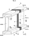
- FIG. 3 is a schematic diagram illustrating the outer member before forming.
- An outer member 14a illustrated in Fig. 3 is the outer member before forming.
- the outer member 14a is the outer member 14 before being joined to the inner member 12.
- an outer member 14Aa, an outer member 14Ba, and an outer member 14Ca as the outer members 14a are connected to form a connection member 15a.
- reinforcing fibers 32 and resin fibers 34a are formed only in a region of a part of the outer member 14a. Actually, however, the reinforcing fibers 32 and the resin fibers 34a are formed in the entire region of the outer member 14a.
- the outer member 14a is a cylindrical member that extends along the direction Y, and the opening 36 is formed across a region from one end portion to another end portion along the direction Y.
- the outer member 14a is formed by weaving the reinforcing fibers 32 as the first reinforcing fibers and the resin fibers 34a with each other. That is, the outer member 14a is a commingled material formed of a carbon fiber reinforced thermo plastic.
- the reinforcing fibers 22 of the inner member 12 are covered with the layer of the resin 24.
- the reinforcing fibers 32 and the resin fibers 34a are exposed to the outside without being covered with another layer such as a resin layer.
- the opening 36 is formed on one end portion of the outer member 14a along the direction Y and does not have to extend up to another end portion of the outer member 14a along the direction Y as long as the inner member 12 can be inserted into the opening 36. That is, the outer member 14a may have a bag shape. In addition, a member that absorbs impact may be provided on a surface of the outer member 14a.
- the length along the direction Y that is, the length in which the opening 36 is formed is longer than the lengths along the direction X and the direction Z, but the relationship between the lengths is not limited thereto.
- the length along the direction Y may be shorter than the lengths along the direction X and the direction Z.
- the outer member 14a has a cylindrical shape or a bag shape.
- the outer member 14a is a hollow member including a space 35 and the opening 36.
- the opening 36 is formed at one end portion of the outer member 14a.
- the space 35 is provided inside the outer member 14a.
- the opening 36 and the space 35 communicate with each other. Accordingly, in the outer member 14a, as described below, the inner member 12 can be inserted from the opening 36 into the space 35.
- the opening 36 is provided at each of one end portion and another end portion, and each of the openings 36 has a shape (cylindrical shape) communicating with the space 35.
- the opening 36 may be provided only at one end portion. In this case, the outer member 14a has a shape (bag shape) in which another end portion is blocked.
- the reinforcing fibers 32 of the outer member 14a extend in an undulating manner by being woven.
- the reinforcing fibers 32 extending along the direction Z undulate in both directions along the direction Y as they approach the direction Z as the extending direction. That is, the reinforcing fibers 32 extend to be inclined to the direction Y side as they approach the direction Z, and extend to be inclined to be opposite to the direction Y as they further approach the direction Z.
- the reinforcing fibers 32 extend in an undulating manner while repeating the above-described movement.
- a portion 32a of the reinforcing fibers 32 and a portion 32b of the reinforcing fibers 32b that is positioned on the direction Z side further than the portion 32a are positioned at different positions in the direction Y. That is, the portion 32b is positioned on the direction Y side further than the portion 32a.
- the reinforcing fibers 22 of the inner member 12 extend linearly, whereas the reinforcing fibers 32 of the outer member 14a extend in an undulating manner.
- the reinforcing fibers 22 of the inner member 12 do not have to be completely linear.
- the undulation (the difference in height between the portion 32a and the portion 32b) of the reinforcing fibers 32 of the outer member 14a may be greater than that of the reinforcing fibers 22 of the inner member 12. This way, the reinforcing fibers 32 extend in an undulating manner such that the bend allowance of the outer member 14a is secured and profile forming is simple.
- the reinforcing fiber 32 is a carbon fiber formed of carbon and is formed of the same material as the reinforcing fiber 22 of the inner member 12.
- the reinforcing fiber 32 may be a fiber in which a carbon fiber and a resin fiber are mixed.
- the reinforcing fiber 32 may be formed of a material different from the reinforcing fiber 22 and may include, for example, another plastic fiber, a glass fiber, or a metallic fiber instead of the carbon fiber.
- a conductive metallic fiber as the reinforcing fiber 32, the conductivity of the surface of the composite material 10 can be improved, and lightning resistance can be improved.
- a conductive metallic fiber as the reinforcing fiber 22 of the inner member 12 a current can be made to flow through the inside of the composite material 10 along the Y direction, and a function as electric wire can also be imparted thereto.
- the resin fiber 34a is a fiber including a resin and more specifically is a resin including a thermoplastic resin.
- the resin fiber 34a is formed of a thermoplastic resin and does not include another material other than unavoidable impurities.
- the resin fiber 34a may include another material component as long as it includes at least a thermoplastic resin.
- the resin fiber 34a is obtained by forming the same thermoplastic resin as the resin 24 of the inner member 12 in a fibrous form.
- As the resin fiber 34a that is a thermoplastic resin for example, polyether ether ketone (PEEK), polyether ketone ketone (PEKK), or polyphenylene sulfide (PPS) is used.
- the resin fiber 34a may be formed of a material different from the resin 24 of the inner member 12 as long as it is a fibrous member including a thermoplastic resin.
- the outer member 14a is a member that is formed in a cylindrical shape by weaving the reinforcing fibers 32 and the resin fibers 34a with each other.
- the resin fibers 32 extend along the outer circumference, and the resin fibers 34a extend to mingle with the reinforcing fibers 32. That is, the reinforcing fiber 32 extends in a direction intersecting the resin fiber 34a and passes through a gap between two adjacent resin fibers 34a.
- the resin fiber 34a also passes through a gap between two adjacent reinforcing fibers 32.
- the reinforcing fibers 32 and the resin fibers 34a are woven, for example, by double plain weaving. In addition, as illustrated in Fig.
- the reinforcing fibers 32 extend in a direction of a circumference with a central axis of the outer member 14a as the center when seen from the direction Y, that is, a circumferential direction.
- the reinforcing fibers 32 are provided along the direction Y.
- the resin fibers 34a extend along the direction Y, are provided along the circumferential direction of the outer member 14a, and are woven with the reinforcing fibers 32.
- the reinforcing fibers 32 do not have to extend along the circumferential direction with the central axis of the outer member 14a as the center and may extend along another direction.
- the reinforcing fibers 32 continuously extend across the circumference of the outer member 14a in the circumferential direction. That is, the reinforcing fiber 32 is a continuous fiber. However, the reinforcing fiber 32 is not limited to a continuous fiber and may be discontinuous halfway the circumference. In addition, the reinforcing fibers 32 extend along the circumferential direction. Therefore, it can be said that, assuming that the extending direction of the reinforcing fibers 22 of the inner member 12 is an axis direction, the reinforcing fibers 32 extend along the circumferential direction. That is, it can be said that the reinforcing fibers 32 extend around the reinforcing fibers 22 in the circumferential direction.
- the reinforcing fibers 22 of the inner member 12 extend in a direction (here, the direction Y) in which a main load is applied and the reinforcing fibers 32 of the outer member 14a extend in the circumferential direction in which the reinforcing fibers 22 are bundled.
- the outer member 14a includes a plurality of reinforcing fibers 32 but may include only one reinforcing fiber 32.
- the reinforcing fiber 32 continuously extends across a plurality of circumferences of the outer member 14a in the circumferential direction.
- the outer member 14a may include a plurality of resin fibers 34a extending along the Y direction but may include only one resin fiber 34a. In this case, the resin fiber 34a is folded at an end portion of the outer member 14a along the Y direction and is arranged along the circumferential direction of the outer member 14a.
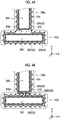
- Fig. 4A is a schematic partial view illustrating the outer member before forming.
- the outer member 14Aa, the outer member 14Ba, and the outer member 14Ca are connected to each other.
- the reinforcing fibers 32 in the connection portion will be described.
- the connection portions between the outer member 14Ba and the outer member 14Ca that is, the connection portions 37B2 and 37C will be described.
- the connection portion 37B2 and the connection portion 37C are connected to each other to be integrated.
- the reinforcing fibers 32 and the resin fibers 34a are also provided in the connection portions 37B2 and 37C.
- the outer member 14Ba includes reinforcing fibers 32A and reinforcing fibers 32B as the reinforcing fibers 32.
- the outer member 14Ca includes reinforcing fibers 32C as the reinforcing fibers 32.
- the reinforcing fibers 32A extend along the circumferential direction of the outer member 14Ba and are provided across the circumference of the outer member 14Ba. That is, the reinforcing fibers 32A are woven in the connection portion 37B2.
- the reinforcing fibers 32C extend along the circumferential direction of the outer member 14Ca and are provided across the circumference of the outer member 14Ca. That is, the reinforcing fibers 32C are also woven in the connection portion 37C.
- the reinforcing fibers 32B are provided across a range from the outer circumferential surface of the outer member 14Ba to the outer circumferential surface of the outer member 14Ca. That is, the reinforcing fibers 32A are provided around the outer circumference of the outer member 14Ba and is not provided in the other outer members 14Aa and 14Ca. The reinforcing fibers 32B are provided around the entire outer circumference of the connection member 15a (an aggregate of the outer member 14a). In other words, the reinforcing fibers 32B are provided across a plurality of outer members 14. The reinforcing fibers 32B are not provided in the connection portions 37B2 and 37C.
- the reinforcing fibers 32B are provided across all the outer members 14Aa, 14Ba, and 14Ca and only have to be provided across at least two outer members 14a adjacent to each other.
- the reinforcing fibers 32 in the connection portions 37A and 37B1 between the outer member 14Aa and the outer member 14Ba are also woven with the reinforcing fibers 32 in the connection portions 37B2 and 37C, and thus the description thereof will not be made.
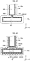
- Figs. 4B to 4D are other examples of a schematic partial view illustrating the outer member before forming.
- the arrangement of the reinforcing fibers in the connection portions 37B2 and 37C is not limited to the example of Fig. 4A .
- the reinforcing fibers 34Bs may extend up to the inside of the connection portions 37B2 and 37C. In this case, it is preferable that the reinforcing fibers 34Bs extend along the direction Z in the connection portions 37B2 and 37C.
- peeling can be favorably inhibited by the reinforcing fibers 34Bs.
- a reinforcing fiber 32Bt may intersect each other in the connection portions 37B2 and 37C.
- one reinforcing fiber is illustrated.
- the reinforcing fibers 32Bt may intersect each other in the connection portions 37B2 and 37C.
- a member 40 may be provided in the connection portions 37B2 and 37C.
- the member 40 is a member including reinforcing fibers 41 and a resin layer 42 and is a UD material as in the inner member 12.
- a decrease in strength in the connection portions 37B2 and 37C can be favorably inhibited.
- the member 40 does not have to be a UD material as long as it is a member including reinforcing fibers.
- the member 40 is provided in the structure illustrated in Fig. 4A but may also be provided in the structures illustrated in Figs. 4B and 4C .
- the outer member 14a is a member that includes the reinforcing fibers 32 extending in an undulating manner and is formed in a cylindrical shape by weaving the reinforcing fibers 32 and the resin fibers 34a with each other.
- the reinforcing fibers 32 are fibers in which carbon fibers and resin fibers are mixed
- the resin fibers 34a do not have to be woven. That is, in the outer member 14a, the reinforcing fibers 32 in which carbon fibers and resin fibers are mixed may be woven with each other. In this case, it is not necessary that two reinforcing fibers 32 are woven as in the reinforcing fibers 32 and the resin fibers 34a illustrated in Fig. 3 .
- One reinforcing fiber 32 may be woven, in other words, may be knitted.
- reinforcing fibers in which carbon fibers and resin fibers are mixed and reinforcing fibers that are carbon fibers and do not include resin fibers may be woven with each other.
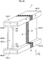
- Fig. 5A is a schematic diagram illustrating the outer member after forming.
- the resin fibers 34a in the outer member 14a are formed of a thermoplastic resin, and thus are melted by heating.
- the melted resin fibers 34a become a liquid resin, flow, are impregnated into the reinforcing fibers 32, and cover the circumference of the reinforcing fibers 32.
- this liquid resin is cooled, the liquid resin is cured to form a resin 34.
- the outer member 14 is formed when the resin fibers 34a in the outer member 14a are melted and converted into the resin 34. That is, as illustrated in Fig.
- the outer member 14 is formed of a composite material including the reinforcing fibers 32 and the resin 34, in which the reinforcing fibers 32 are impregnated with the resin 34. More specifically, in the outer member 14, the reinforcing fibers 32 extend along the circumferential direction in the resin 34 as a base material. In addition, the reinforcing fibers 32 are woven with the resin fibers 34a in the state of the outer member 14a, and thus extend in an undulating manner. Accordingly, in the outer member 14, the reinforcing fibers 32 extend in an undulating manner while maintaining the state of the outer member 14a.
- Fig. 5B is another example of a schematic diagram illustrating the outer member after forming.
- the portion of the carbon fibers remain without being melted.
- the portion of carbon fibers 34b woven into the reinforcing fibers 32 remain.
- the outer member 14 after molding has a structure in which the reinforcing fibers 32 and the carbon fibers 34b that are woven with each other are covered with (impregnated with) the resin 34. This way, by allowing the carbon fibers 34b to remain, a state where the reinforcing fibers 32 are bundled by the carbon fibers 34b can be maintained, and a decrease in strength can be more favorably inhibited.
- the composite material 10 includes the inner member 12 and the outer member 14 having the above-described structures.
- production steps of the composite material 10 will be described.
- Fig. 6 is a diagram illustrating the production steps of the composite material.
- the inner member 12 and the outer member 14a before forming are prepared.
- the prepared inner member 12 may be in a state of a prepreg before the curing of the resin 24 or may be in a state after the curing of the resin 24.
- the inner member 12 is inserted into the outer member 14a (Step S10; insertion step). Specifically, the inner member 12A is inserted from the opening 36A of the outer member 14Aa into the space 35 thereof such that the inner member 12A is arranged in the outer member 14Aa. In addition, the inner member 12B is inserted from the opening 36B of the outer member 14Ba into the space 35 thereof such that the inner member 12B is arranged in the outer member 14Ba. In addition, the inner member 12C is inserted from the opening 36C of the outer member 14Ca into the space 35 thereof such that the inner member 12C is arranged in the outer member 14Ca.
- Step S10 the inner circumference of the outer member 14a and the outer circumference of the inner member 12 are not joined.
- the inner circumference of the outer member 14a and the outer circumference of the inner member 12 are partially separated from each other without adhering to each other.
- a resin film may be inserted between the inner circumference of the outer member 14a and the outer circumference of the inner member 12 to improve joining properties.
- the inner members 12 are inserted into the outer member 14a. However, only a part of the inner members 12 may be inserted into the outer member 14a. For example, in the insertion step, only a portion of the inner member 12 to be heated in the subsequent step may be inserted into the outer member 14a. For example, when the composite material 10 is joined to another member, the composite material 10 may be joined to another member after Step S16 described below. In this case, the inner member 12 on a surface to be joined to another member does not have to be inserted in the insertion step. When the inner member 12 is joined to another member, the inner member 12 is inserted into the outer member 14a and is heated for joining to the other member to be joined to the outer member 14.
- the outer member 14a into which the inner member 12 is inserted is arranged in molds 50 and 52.
- the mold 50 is pressed against one surface of the outer member 14a along the direction X
- the mold 52 is pressed against another surface of the outer member 14a along the direction X. That is, the outer member 14a is interposed between the mold 50 and the mold 52 to be accommodated in the molds 50 and 52.
- the outer member 14a is pressurized and heated in the molds 50 and 52 (Step S12; heating step). In the heating step, the outer member 14a is heated up to a temperature higher than or equal to a melting point of the resin fibers 34a.
- the resin fibers 34a are melted to become a liquid resin.
- This liquid resin flows, is impregnated into the reinforcing fibers 32, and covers the circumference of the reinforcing fibers 32.
- the outer member 14a is formed of the liquid resin, an outer circumferential shape thereof is determined, for example, by the molds 50 and 52.
- the resin 24 of the inner member 12 is also melted. Accordingly, a space between the inner circumference of the outer member 14a and the outer circumference of the inner member 12 is closed (filled) with the melted resin 24 of the inner member 12 or the melted resin of the resin fibers 34a. Accordingly, the opening 36 of the outer member 14a is closed with the inner member 12.
- Step S14 After heating the outer member 14a into which the inner member 12 is inserted, the outer member 14a into which the inner member 12 is inserted is cooled (Step S14; cooling step).
- the cooling step the outer member 14a into which the inner member 12 is inserted is cooled up to a temperature lower than the melting point of the resin fibers 34a and is held at this temperature for a predetermined time in the molds 50 and 52. Accordingly, the melted resin of the resin fibers 34a is cured as the resin 34 and becomes the outer member 14.
- the resin 24 of the inner member 12 is also cured. By curing the liquid resin having a desired shape in the molds 50 and 52, the resin is cured while maintaining the desired shape. As a result, the composite material 10 is formed.
- the inner member 12 and the outer member 14 are joined to each other by curing the resin.
- the heating step and the cooling step correspond to the composite material forming step.
- the composite material 10 is extracted from the molds 50 and 52 (Step S16; extraction step), and the production steps of the composite material 10 ends.
- a thermosetting resin is used as the resin 24 and the inner member 12 in a state of a prepreg is used in the preparation step, the resin 24 is cured in the heating step.
- a thermosetting resin is used as the resin 24 and the cured inner member 12 is used in the preparation step, the shape of the inner member 12 does not change in the heating step and the cooling step.
- the inner member 12 is a member in which the reinforcing fibers are impregnated with the resin in a state of a prepreg.
- the member in which the reinforcing fibers are impregnated with the resin in a state of a prepreg has a plate shape even in a state of a prepreg. Therefore, for example, it is difficult to bent the member, and it is difficult to form a complex shape.
- the commingled material such as the outer member 14 has a structure in which the resin fibers as a resin and the reinforcing fibers are woven with each other in a state of a prepreg (before forming). More specifically, the reinforcing fibers extend in an undulating manner. Accordingly, even a complex shape can be realized by bending or the like. However, the commingled material tends to have a lower strength than the member in which the reinforcing fibers are impregnated with the resin in a state of a prepreg. Accordingly, for the composite material including the reinforcing fibers and the resin, it is required that a desired shape can be easily realized and a decrease in strength can be inhibited.
- the composite material 10 according to the embodiment is produced by the insertion step and the composite material step.
- the inner member 12 is inserted into the space 35 in the outer member 14a.
- the outer member 14a is formed of the woven reinforcing fibers 32 (first reinforcing fiber) extending in an undulating manner, the outer member 14a including the opening 36 that is provided at at least one end portion and the space 35 that communicates with the opening; 36.
- the reinforcing fibers 22 (second reinforcing fiber) are impregnated with the resin 24.
- the composite material forming step the composite material 10 is formed by curing the resin 24 of the inner member 12 to join the outer member 14 and the inner member 12 to each other. In the composite material 10, the outer member 14 and the inner member 12 are joined.
- the reinforcing fibers 22 are impregnated with the resin 24.
- the outer member 14a is formed in a shape in which the opening 36 and the space 35 communicate with each other, that is, in a cylindrical shape by weaving the reinforcing fibers 32, and the reinforcing fibers 32 extend in an undulating manner by being woven.
- the outer member 14a covers the inner member 12. By curing the resin 24 of the inner member 12, the outer member 14 and the inner member 12 are joined to each other.
- the composite material 10 produced as described above has a structure in which the inner member 12 is provided in the outer member 14, in other words, a structure in which the outer member 14 is close to the circumference of the inner member 12.
- the reinforcing fibers 32 extend in an undulating manner, and thus the degree of freedom for the shape is high. Accordingly, in the production method, the internal strength can be improved by the inner member 12 in a state where the outer shape is formed by the outer member 14a. Accordingly, in the composite material 10 produced using the above-described production method, a desired shape can be easily realized, and a decrease in strength can be favorably inhibited.
- connection member 15a is formed by connecting the outer circumferential surfaces of the outer members 14a.
- the composite material 10 is produced using the connection member 15a in which the outer circumferential surfaces of the cylindrical outer members 14a are connected. Accordingly, in the composite material 10 produced using the above-described production method, a desired shape can be easily realized, and a decrease in strength can be inhibited.
- connection member 15a the reinforcing fibers 32 as the first reinforcing fiber are provided across the outer members 14a. Accordingly, in the connection member 15a, a decrease in the strength of the surface can be more favorably inhibited. In addition, the reinforcing fibers 32 are continuous across the outer members 14. Therefore, for example, even when a part of the reinforcing fibers 32 are damaged, the strength can be secured by another portion of the reinforcing fibers 32.
- the outer member 14a is formed of woven fibers including a thermoplastic resin.
- the thermoplastic resin included in the outer member 14a is melted and cured to join the outer member 14a and the inner member 12 to each other.
- the outer member 14a is a commingled material formed of woven fibers including a thermoplastic resin. Accordingly, in the production method, the internal strength can be improved by the inner member 12 in a state where the outer shape is formed by the outer member 14 as the commingled material. Accordingly, in the composite material 10 produced using the above-described production method, a desired shape can be more easily realized.
- the resin 24 of the inner member 12 is a thermoplastic resin that is the same material as the resin fibers 34a.
- the inner member 12 and the outer member 14 can be favorably joined to each other.
- the inner member 12 is an unidirectional material in which the reinforcing fibers 22 (second reinforcing fiber) extending in one direction are impregnated with the resin 24.
- the unidirectional material By using the unidirectional material as the inner member 12, a decrease in the strength of the composite material 10 can be more favorably inhibited.
- the reinforcing fibers 32 first reinforcing fiber
- the reinforcing fibers 22 second reinforcing fiber
- the reinforcing fibers 32 and the reinforcing fibers 22 can also be formed of different materials. In this case, an appropriate function can be imparted to the outer member 14 while imparting an appropriate function to the inner member 12.
- Fig. 7 is a schematic diagram illustrating another example of the heating step.
- a pressurizing member 54 is brought into contact with an outer circumferential surface 16 of the outer member 14a.
- the pressurizing member 54 pressurizes the outer circumferential surface 16.
- the outer member 14a does not enter the molds 50 and 52, and a surface of the outer member 14a opposite to the outer circumferential surface 16 with which the pressurizing member 54 is brought into contact is open without being pressurized.
- the outer circumferential surface 16 of the outer member 14a is pressed by the pressurizing member 54, and an inner circumferential surface 18 of the outer member 14a is supported by the inner member 12. Accordingly, the outer member 14a is pressed (pressurized) by the pressurizing member 54 and the inner member 12.
- the heating step for example, the outer circumferential surface 16 of the outer member 14a that is pressed, for example, by the pressurizing member 54 is heated.
- the thermoplastic resin in the pressed outer member 14a is melted.
- the inner member 12 also includes a thermoplastic resin
- the thermoplastic resin on the surface of the inner member 12 is also melted and mixed with the thermoplastic resin of the outer member 14a.
- the outer member 14 having a desired shape can be obtained.
- the inner member 12 has rigidity to some extent. Accordingly, for example, the pressurizing member 54 may be held at a temperature lower than a melting temperature of the resin 24 with respect to the inner member 12. In addition, by heating the pressurizing member 54 to a temperature higher than the melting temperature of the resin 24 of the inner member 12, an interface of the inner member 12 may be mixed with an interface of the outer member 14. In addition, it is also preferable that the inner member 12 including the cured resin 24 as a thermosetting resin is used. In this case, it is preferable that an adhesive layer is provided between the inner member 12 and the resin 24 for adhesion between the inner member 12 and the resin 24. That is, a film-shaped adhesive may be interposed between the inner member 12 and the resin 24, or may be applied to a gap between the inner member 12 and the resin 24.
- a heat generating member 60 may be arranged between the inner member 12 and the outer member 14a.
- the pressurizing member 54 is brought into contact with the outer circumferential surface 16 of the outer member 14a in a state where the heat generating member 60 is provided between the inner member 12 and the outer member 14a.
- the heat generating member 60 generates heat and is a sheet-like member that covers the outer circumferential surface of the inner member 12, in other words, the inner circumferential surface 18 of the outer member 14a.
- the heat generating member 60 heats the outer member 14a from the inner circumferential surface 18 side.
- the heat generating member 60 can promote the heating by assisting the heating to the inside of the outer member 14a.
- the heat generating member 60 generates heat in the heating step and does not generate heat in the other steps.
- the heat generating member 60 is a member that has little effect on strength even when it remains in the composite material 10.
- the heat generating member 60 include a heat generating film including metal powder that generates heat using an electromagnetic field or the like and a film on which a heat generating electrode is printed.
- a heat generating circuit may be directly printed on the inner member 12.
- the heat generating member 60 may be an uneven film that functions as an energy director for the pressurizing member 54.
- the surface of the inner member 12 may be formed in an uneven shape in advance. In this case, for example, the uneven shape can be realized by depositing the heated resin on the surface of the inner member 12 by sputtering.
- the film used as the heat generating member 60 is formed of the same material as the resin of the inner member 12 or the outer member 14, the film is mixed after heating, which is preferable. The heat generating member 60 does not have to be provided.
- Fig. 8 is a diagram illustrating another example of a shape of the composite material.
- the composite material 10 has an I-shape, but the shape is not limited thereto as described above.
- a composite material 10b may have a aerofoil shape.
- the composite material 10b is produced through the same steps as those of the composite material 10 and has a shape in which the circumference of an inner member 12b as a core is covered with an outer member 14b.
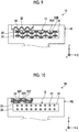
- Fig. 9 is an example of a partial view illustrating the outer member after forming.
- the outer member 14a is formed in a cylindrical shape by weaving the reinforcing fibers 32 not including resin fibers and the resin fibers 34a with each other and the reinforcing fibers 22 of the inner member 12 are woven with each other in the inner layer 25, the structure of the composite material 10 after forming is as illustrated in Fig. 9 . That is, as illustrated in Fig. 9 , the outer member 14 included in the composite material 10 is a cylindrical member including the reinforcing fibers 32 (first reinforcing fiber) and the resin 34 (resin layer) that covers the reinforcing fibers 32. In this case, the reinforcing fibers 32 are not woven with other fibers.
- the inner member 12 is provided close to the inside of the outer member 14.
- the outer member 14 is provided close to the circumference of the inner member 12.
- the inner member 12 is a member in which inner layers 25 each of which includes reinforcing fibers 22A and 22B (second reinforcing fibers) intersecting each other and the resin 24 covering the reinforcing fibers 22A and 22B overlap each other.
- this composite material 10 a desired shape can be easily realized, and a decrease in strength can be favorably inhibited.
- the outer member 14 is a commingled material formed of woven fibers including a thermoplastic resin.
- the outer member 14 is not limited to a commingled material as long as it is formed in a cylindrical shape using woven reinforcing fibers 32 extending in an undulating manner.
- Fig. 10 is a schematic diagram illustrating another example of the composite material. As illustrated in Fig. 10 , for example, an outer member 14S may be formed by three-dimensionally weaving reinforcing fibers 32X, 32Y, and 32Z (second reinforcing fibers).
- the reinforcing fibers 32X, 32Y, and 32Z are formed of the same material as the reinforcing fibers 32 and does not include resin fibers. However, the reinforcing fibers 32X, 32Y, and 32Z may include resin fibers.
- the reinforcing fibers 32X extend along, for example, the direction X
- the reinforcing fibers 32Y extend along, for example, the direction Y
- the reinforcing fibers 32Z extend along, for example, the direction Z.
- the reinforcing fibers 32X and the reinforcing fibers 32Y are woven with each other.
- the woven shape refers to a shape in which, for example, among two reinforcing fibers 32Y adjacent to each other along the X direction, one reinforcing fiber 32Y is positioned above one reinforcing fiber 32X along the Z direction and another reinforcing fiber 32Y is positioned below the same reinforcing fiber 32X along the Z direction.
- the reinforcing fiber 32Z meander while being inserted between the reinforcing fibers 32X and 32Y, and extends along the direction X or the direction Y. That is, the reinforcing fibers 32X, 32Y, and 32Z extend in an undulating manner by being woven.
- the reinforcing fibers 32X, 32Y, and 32Z are not exposed to the outside without being covered with the resin layer.
- the melted resin 24 flowing out from the inner member 12 is impregnated into the reinforcing fibers 32X, 32Y, and 32Z such that the reinforcing fibers 32X, 32Y, and 32Z are covered with the resin 24 after forming.
- the surfaces of the reinforcing fibers 32X, 32Y, and 32Z may be covered with the resin before forming by applying a small amount of the resin thereto. In this case, the reinforcing fibers 32X, 32Y, and 32Z extend in an undulating manner. Therefore, even in the outer member 14S, a desired shape can be easily realized.
- the outer member 14S is a cylindrical member including: woven reinforcing fibers 32X, 32Y, and 32Z (a plurality of first reinforcing fibers) intersecting each other; and a resin layer that covers the reinforcing fibers 32X, 32Y, and 32Z.
- the inner member 12 is provided close to the inside of the outer member 14S.
- the outer member 14S is provided close to the circumference of the inner member 12.
- the inner member 12 is a member in which the inner layers 25 each of which includes a plurality of reinforcing fibers 22 (second reinforcing fibers) extending in one direction and the resin 24 covering the reinforcing fibers 22 overlap each other.
- the outer member 14 before forming is a cylindrical member including: a plurality of woven first reinforcing fibers intersecting each other; and a resin layer that covers the first reinforcing fibers.
- the inner member 12 is a member in which the inner layers 25 each of which includes a plurality of reinforcing fibers 22 (second reinforcing fibers) extending in one direction and the resin 24 covering the reinforcing fibers 22 overlap each other. In this composite material 10, a desired shape can be easily realized, and a decrease in strength can be favorably inhibited.
- the embodiments of the present invention have been described. However, the embodiments are not limited to the contents of the embodiments.
- the above-described components include components that can be easily conceived by those skilled in the art, components substantially the same as the components, and components within a range of so-called equivalents. Further, the above-described components can be appropriately combined with each other. Further, various omissions, substitutions, or changes can be made for the components within a range not departing from the scope of the embodiments.
Landscapes
- Engineering & Computer Science (AREA)
- Chemical & Material Sciences (AREA)
- Composite Materials (AREA)
- Mechanical Engineering (AREA)
- Textile Engineering (AREA)
- Moulding By Coating Moulds (AREA)
- Reinforced Plastic Materials (AREA)
- Lining Or Joining Of Plastics Or The Like (AREA)
Abstract
Description
- The present invention relates to a method for producing a composite material and a composite material.
- A composite material including a resin and reinforcing fibers is lighter than a metal material and further has higher specific strength and specific rigidity. Therefore, the composite material is used for various applications including a member of an aircraft. Typically, when a member is formed using this composite material, a sheet-shaped prepreg in which reinforcing fibers are impregnated with a resin is laminated for forming the member. For example,
PTL 1 describes a configuration in which a laminate of a unidirectional material and a laminate of a random material are laminated. The unidirectional material is a sheet-shaped unidirectional (UD) material in which extending directions of reinforcing fibers are aligned in one direction. In addition, the random material is a sheet-shaped member in which extending directions of reinforcing fibers are random. - [PTL 1] Japanese Unexamined Patent Application Publication No.
2016-5955 - However, when a unidirectional material or a random material is laminated to form a member, the strength of the compact increases, but it is difficult to realize a complex shape. Therefore, a composite material in which a desired shape can be easily realized and a decrease in strength can be inhibited is required.
- The present invention has been made in order to solve the above-described problems, and an object thereof is to provide: a method for producing a composite material in which a desired shape can be easily realized and a decrease in strength can be inhibited; and the composite material.
- In order to solve the above-described problems and to achieve the object, according to the present disclosure, there is provided a method for producing a composite material, the method including: an insertion step of inserting an inner member in which a second reinforcing fiber is impregnated with a resin into a space of an outer member that is formed of a woven first reinforcing fiber extending in an undulating manner, the outer member including an opening that is provided at at least one end portion and the space that communicates with the opening; and a composite material forming step of forming a composite material in which the outer member and the inner member are joined to each other by curing the resin of the inner member to join the outer member and the inner member to each other.
- In the method for producing a composite material, the internal strength can be improved by the inner member in a state where the outer shape is formed by the outer member as a commingled material. Accordingly, in the production method, a composite material in which a desired shape can be easily realized and a decrease in strength can be inhibited can be produced.
- It is preferable that, in the insertion step, the inner member is inserted into each of a plurality of outer members of a connection member, the connection member being formed by connecting outer circumferential surfaces of the outer members to each other.
- It is preferable that, in the connection member, the first reinforcing fiber is provided across the outer members.
- It is preferable that, in the insertion step, the inner member is inserted into the outer member while providing a heat generating member between the inner member and the outer member.
- It is preferable that the outer member is formed of a woven fiber including a thermoplastic resin, and it is preferable that, in the composite material forming step, the thermoplastic resin included in the outer member is melted and cured to join the outer member and the inner member to each other.
- It is preferable that the resin of the inner member is a thermoplastic resin that is the same material as the resin fiber.
- It is preferable that the outer member is formed of the first reinforcing fiber that is three-dimensionally woven.
- It is preferable that the inner member is a unidirectional material in which a plurality of second reinforcing fibers extending in one direction are impregnated with a resin.
- It is preferable that the first reinforcing fiber and the second reinforcing fiber are formed of the same material.
- In order to solve the above-described problems and to achieve the object, according to the present disclosure, there is provided a composite material that is produced using the above-described method for producing a composite material.
- In order to solve the above-described problems and to achieve the object, according to the present disclosure, there is provided a composite material including: an outer member including a woven first reinforcing fiber and a resin layer that covers the first reinforcing fiber; and an inner member in which inner layers each of which includes a plurality of second reinforcing fibers extending in one direction and a resin covering the second reinforcing fibers overlap each other, in which the outer member is provided close to a circumference of the inner member.
- In order to solve the above-described problems and to achieve the object, according to the present disclosure, there is provided a composite material including: an outer member including a first reinforcing fiber and a resin layer that covers the first reinforcing fiber; and an inner member in which inner layers each of which includes a woven second reinforcing fiber and a resin covering the second reinforcing fiber overlap each other, in which the outer member is provided close to a circumference of the inner member.
- According to the present invention, a desired shape can be easily realized and a decrease in strength can be inhibited.
-
-
Fig. 1 is a schematic diagram illustrating a configuration of a composite material according to an embodiment. -
Fig. 2 is a schematic cross-sectional view illustrating an inner member. -
Fig. 3 is a schematic diagram illustrating an outer member before forming. -
Fig. 4A is a schematic partial view illustrating the outer member before forming. -
Fig. 4B is another example of a schematic partial view illustrating the outer member before forming. -
Fig. 4C is still another example of a schematic partial view illustrating the outer member before forming. -
Fig. 4D is still another example of a schematic partial view illustrating the outer member before forming. -
Fig. 5A is a schematic diagram illustrating the outer member after forming. -
Fig. 5B is another example of a schematic diagram illustrating the outer member after forming. -
Fig. 6 is a diagram illustrating production steps of the composite material. -
Fig. 7 is a schematic diagram illustrating another example of a heating step. -
Fig. 8 is a diagram illustrating another example of a shape of the composite material. -
Fig. 9 is an example of a partial view illustrating the outer member after forming. -
Fig. 10 is a schematic diagram illustrating another example of the composite material. - Hereinafter, a preferable embodiment of the present invention will be described in detail with reference to the accompanying drawings. The present invention is not limited to this embodiment. In addition, in a case where a plurality of embodiments are provided, the present invention also includes a combination of two or more of the embodiments.
-
Fig. 1 is a schematic diagram illustrating a configuration of a composite material according to an embodiment. Acomposite material 10 according to the embodiment is a member that is used for a product such as an aircraft. In the embodiment, thecomposite material 10 is a member having an I-shaped cross-section, but the present invention is not limited to this shape. In addition, hereinafter, a direction X, a direction Y perpendicular to the direction X, and a direction Z perpendicular to the direction X and the direction Y are defined. - As illustrated in
Fig. 1 , thecomposite material 10 according to the embodiment includes:inner members outer members outer member 14A is a cylindrical member having an opening 36A. Theouter member 14B is a cylindrical member having an opening 36B. Theouter member 14C is a cylindrical member having an opening 36C. Aconnection portion 37A of theouter member 14A is connected to a connection portion 37B1 of theouter member 14B. In addition, aconnection portion 37C of theouter member 14C is connected to a connection portion 37B2 of theouter member 14B. Theconnection portion 37A is an outer circumferential portion having a cylindrical shape of theouter member 14A. The connection portions 37B1 and 37B2 are outer circumferential portions having a cylindrical shape of theouter member 14B. Theconnection portion 37C is an outer circumferential portion having a cylindrical shape of theouter member 14C. That is, the outer circumferential surfaces of theouter members connection member 15. Theconnection member 15 is formed in an I shape having theopenings outer members outer members outer members outer members outer member 14. Likewise, when it is not necessary to distinguish between theopenings openings opening 36. - The
inner member 12A is provided inside theopening 36A of theouter member 14A, and an outer circumferential surface thereof is joined to an inner circumferential surface (an outer circumferential surface of theopening 36A) of theouter member 14A. Theinner member 12B is provided inside theopening 36B of theouter member 14B, and an outer circumferential surface thereof is joined to an inner circumferential surface (an outer circumferential surface of theopening 36B) of theouter member 14B. Theinner member 12C is provided inside theopening 36C of theouter member 14C, and an outer circumferential surface thereof is joined to an inner circumferential surface (an outer circumferential surface of theopening 36C) of theouter member 14C. That is, theinner members openings outer members inner members inner members inner member 12. -
Fig. 2 is a schematic cross-sectional view illustrating the inner member. Theinner member 12 is a composite material including a reinforcingfiber 22 as a second reinforcing fiber and aresin 24, in which the reinforcingfiber 22 is impregnated with theresin 24. The reinforcingfiber 22 has higher strength than theresin 24. The reinforcingfiber 22 is a carbon fiber formed of carbon. In addition, theresin 24 is a thermoplastic resin that melts when heated up to a predetermined temperature. As theresin 24 that is a thermoplastic resin, for example, polyether ether ketone (PEEK), polyether ketone ketone (PEKK), or polyphenylene sulfide (PPS) is used. That is, in the embodiment, theinner member 12 is formed of carbon fiber reinforced thermo plastics (CFRTP). However, the reinforcingfiber 22 is not limited to carbon fiber and may be another plastic fiber, a glass fiber, or a metallic fiber. However, theresin 24 is not limited to a thermoplastic resin and, for example, may a thermosetting resin. As the thermosetting resin, for example, an epoxy resin is used. - As illustrated in
Fig. 2 , theinner member 12 has a configuration in which a plurality ofinner layers 25 are laminated. Theinner layer 25 is a layer in which a plurality of reinforcingfibers 22 are arranged in the layer of theresin 24 as a base material. However, since theinner layers 25 are joined to each other, it can be said that there is no interface between the inner layers 25. Accordingly, it can be said that theinner layer 25 is a layer including the reinforcingfibers 22 that are arranged in a line and theresin 24 that covers the reinforcingfibers 22. - In the embodiment, in the
inner members inner layers 25 are laminated along the direction Z, and the reinforcingfibers 22 are arranged in theinner layer 25 in the direction X. Regarding theinner members inner member 12B, theinner layers 25 are laminated along the direction X, and the reinforcingfibers 22 are arranged in theinner layer 25 in the direction Z. Regarding theinner member 12B, the length along the direction Z is longer than the length along the direction X, and the length along the direction Y is longer than the length along the direction Z. However, a direction in which theinner layers 25 are laminated in theinner members fibers 22 are arranged in theinner layer 25 can be freely set. - In addition, as illustrated in
Fig. 2 , in theinner member 12, the reinforcingfibers 22 extend linearly along the direction Y in theresin 24 as a base material. That is, theinner member 12 is a unidirectional material, in other words, a UD material. It is preferable that, in theinner member 12, the reinforcingfibers 22 extend along the direction Y in which the length is longest. However, the direction in which the reinforcingfibers 22 extend is not limited to the direction Y as long as the reinforcingfibers 22 are arranged and extend in any direction. In addition, in the embodiment, in all theinner members fibers 22 extend in the same direction. The extending directions of the reinforcingfibers 22 vary depending on theinner members 12. In addition, in theinner member 12, the extending directions of the reinforcingfibers 22 may vary depending on the inner layers 25. In addition, in theinner member 12, the extending directions of the reinforcingfibers 22 do not have to face only one direction and may face a plurality of directions. In addition, in theinner layer 25 of theinner member 12, the reinforcingfibers 22 extending in different directions (for example, the X direction and the Y direction) may be woven with each other. That is, theinner layer 25 may be a cloth material. - In addition, the
inner member 12 does not have to be a laminate in which theinner layers 25 are laminated. For example, theinner member 12 may be configured such that a rope-shaped reinforcing fiber bundle in which the reinforcingfibers 22 are bundled and extend in one direction is covered with theresin 24. That is, theinner member 12 may have a structure in which the circumference of the reinforcingfiber 22 extending linearly is covered with theresin 24. - In addition, the reinforcing
fiber 22 continuously extends from the vicinity of one end portion of theinner member 12 to the vicinity of another end portion thereof along the Y direction. That is, the reinforcingfiber 22 is a continuous fiber. However, the reinforcingfiber 22 is not limited to a continuous fiber and may be discontinuous halfway. In addition, it is preferable that the reinforcingfibers 22 extend linearly. - Next, the
outer member 14 will be described.Fig. 3 is a schematic diagram illustrating the outer member before forming. Anouter member 14a illustrated inFig. 3 is the outer member before forming. In other words, theouter member 14a is theouter member 14 before being joined to theinner member 12. As illustrated inFig. 3 , an outer member 14Aa, an outer member 14Ba, and an outer member 14Ca as theouter members 14a are connected to form aconnection member 15a. For convenience of description, inFig. 3 , reinforcingfibers 32 andresin fibers 34a are formed only in a region of a part of theouter member 14a. Actually, however, the reinforcingfibers 32 and theresin fibers 34a are formed in the entire region of theouter member 14a. - The
outer member 14a is a cylindrical member that extends along the direction Y, and theopening 36 is formed across a region from one end portion to another end portion along the direction Y. Theouter member 14a is formed by weaving the reinforcingfibers 32 as the first reinforcing fibers and theresin fibers 34a with each other. That is, theouter member 14a is a commingled material formed of a carbon fiber reinforced thermo plastic. The reinforcingfibers 22 of theinner member 12 are covered with the layer of theresin 24. On the other hand, in theouter member 14a, the reinforcingfibers 32 and theresin fibers 34a are exposed to the outside without being covered with another layer such as a resin layer. However, the circumference of the reinforcingfibers 32 is covered with the resin without being exposed to the outside. Theopening 36 is formed on one end portion of theouter member 14a along the direction Y and does not have to extend up to another end portion of theouter member 14a along the direction Y as long as theinner member 12 can be inserted into theopening 36. That is, theouter member 14a may have a bag shape. In addition, a member that absorbs impact may be provided on a surface of theouter member 14a. In the example illustrated inFig. 3 , regarding theouter member 14a, the length along the direction Y, that is, the length in which theopening 36 is formed is longer than the lengths along the direction X and the direction Z, but the relationship between the lengths is not limited thereto. For example, regarding theouter member 14a, the length along the direction Y may be shorter than the lengths along the direction X and the direction Z. - This way, the
outer member 14a has a cylindrical shape or a bag shape. In other words, it can be said that theouter member 14a is a hollow member including aspace 35 and theopening 36. Theopening 36 is formed at one end portion of theouter member 14a. Thespace 35 is provided inside theouter member 14a. Theopening 36 and thespace 35 communicate with each other. Accordingly, in theouter member 14a, as described below, theinner member 12 can be inserted from theopening 36 into thespace 35. In the example ofFig. 3 , in theouter member 14a, theopening 36 is provided at each of one end portion and another end portion, and each of theopenings 36 has a shape (cylindrical shape) communicating with thespace 35. However, in theouter member 14a, theopening 36 may be provided only at one end portion. In this case, theouter member 14a has a shape (bag shape) in which another end portion is blocked. - The reinforcing
fibers 32 of theouter member 14a extend in an undulating manner by being woven. In the example ofFig. 3 , the reinforcingfibers 32 extending along the direction Z undulate in both directions along the direction Y as they approach the direction Z as the extending direction. That is, the reinforcingfibers 32 extend to be inclined to the direction Y side as they approach the direction Z, and extend to be inclined to be opposite to the direction Y as they further approach the direction Z. The reinforcingfibers 32 extend in an undulating manner while repeating the above-described movement. More specifically, aportion 32a of the reinforcingfibers 32 and aportion 32b of the reinforcingfibers 32b that is positioned on the direction Z side further than theportion 32a are positioned at different positions in the direction Y. That is, theportion 32b is positioned on the direction Y side further than theportion 32a. This way, the reinforcingfibers 22 of theinner member 12 extend linearly, whereas the reinforcingfibers 32 of theouter member 14a extend in an undulating manner. The reinforcingfibers 22 of theinner member 12 do not have to be completely linear. The undulation (the difference in height between theportion 32a and theportion 32b) of the reinforcingfibers 32 of theouter member 14a may be greater than that of the reinforcingfibers 22 of theinner member 12. This way, the reinforcingfibers 32 extend in an undulating manner such that the bend allowance of theouter member 14a is secured and profile forming is simple. - The reinforcing
fiber 32 is a carbon fiber formed of carbon and is formed of the same material as the reinforcingfiber 22 of theinner member 12. The reinforcingfiber 32 may be a fiber in which a carbon fiber and a resin fiber are mixed. In addition, the reinforcingfiber 32 may be formed of a material different from the reinforcingfiber 22 and may include, for example, another plastic fiber, a glass fiber, or a metallic fiber instead of the carbon fiber. By using a conductive metallic fiber as the reinforcingfiber 32, the conductivity of the surface of thecomposite material 10 can be improved, and lightning resistance can be improved. In addition, by using a conductive metallic fiber as the reinforcingfiber 22 of theinner member 12, a current can be made to flow through the inside of thecomposite material 10 along the Y direction, and a function as electric wire can also be imparted thereto. - The
resin fiber 34a is a fiber including a resin and more specifically is a resin including a thermoplastic resin. Theresin fiber 34a is formed of a thermoplastic resin and does not include another material other than unavoidable impurities. Theresin fiber 34a may include another material component as long as it includes at least a thermoplastic resin. Theresin fiber 34a is obtained by forming the same thermoplastic resin as theresin 24 of theinner member 12 in a fibrous form. As theresin fiber 34a that is a thermoplastic resin, for example, polyether ether ketone (PEEK), polyether ketone ketone (PEKK), or polyphenylene sulfide (PPS) is used. In addition, theresin fiber 34a may be formed of a material different from theresin 24 of theinner member 12 as long as it is a fibrous member including a thermoplastic resin. - The
outer member 14a is a member that is formed in a cylindrical shape by weaving the reinforcingfibers 32 and theresin fibers 34a with each other. In the embodiment, theresin fibers 32 extend along the outer circumference, and theresin fibers 34a extend to mingle with the reinforcingfibers 32. That is, the reinforcingfiber 32 extends in a direction intersecting theresin fiber 34a and passes through a gap between twoadjacent resin fibers 34a. Likewise, theresin fiber 34a also passes through a gap between two adjacent reinforcingfibers 32. The reinforcingfibers 32 and theresin fibers 34a are woven, for example, by double plain weaving. In addition, as illustrated inFig. 3 , the reinforcingfibers 32 extend in a direction of a circumference with a central axis of theouter member 14a as the center when seen from the direction Y, that is, a circumferential direction. The reinforcingfibers 32 are provided along the direction Y. Theresin fibers 34a extend along the direction Y, are provided along the circumferential direction of theouter member 14a, and are woven with the reinforcingfibers 32. However, the reinforcingfibers 32 do not have to extend along the circumferential direction with the central axis of theouter member 14a as the center and may extend along another direction. - In addition, the reinforcing
fibers 32 continuously extend across the circumference of theouter member 14a in the circumferential direction. That is, the reinforcingfiber 32 is a continuous fiber. However, the reinforcingfiber 32 is not limited to a continuous fiber and may be discontinuous halfway the circumference. In addition, the reinforcingfibers 32 extend along the circumferential direction. Therefore, it can be said that, assuming that the extending direction of the reinforcingfibers 22 of theinner member 12 is an axis direction, the reinforcingfibers 32 extend along the circumferential direction. That is, it can be said that the reinforcingfibers 32 extend around the reinforcingfibers 22 in the circumferential direction. More specifically, it is preferable that the reinforcingfibers 22 of theinner member 12 extend in a direction (here, the direction Y) in which a main load is applied and the reinforcingfibers 32 of theouter member 14a extend in the circumferential direction in which the reinforcingfibers 22 are bundled. - In addition, the
outer member 14a includes a plurality of reinforcingfibers 32 but may include only one reinforcingfiber 32. In addition, the reinforcingfiber 32 continuously extends across a plurality of circumferences of theouter member 14a in the circumferential direction. Likewise, theouter member 14a may include a plurality ofresin fibers 34a extending along the Y direction but may include only oneresin fiber 34a. In this case, theresin fiber 34a is folded at an end portion of theouter member 14a along the Y direction and is arranged along the circumferential direction of theouter member 14a. -
Fig. 4A is a schematic partial view illustrating the outer member before forming. As described above, the outer member 14Aa, the outer member 14Ba, and the outer member 14Ca are connected to each other. The reinforcingfibers 32 in the connection portion will be described. In the example ofFig. 4A , the connection portions between the outer member 14Ba and the outer member 14Ca, that is, the connection portions 37B2 and 37C will be described. The connection portion 37B2 and theconnection portion 37C are connected to each other to be integrated. The reinforcingfibers 32 and theresin fibers 34a are also provided in the connection portions 37B2 and 37C. Specifically, the outer member 14Ba includes reinforcingfibers 32A and reinforcingfibers 32B as the reinforcingfibers 32. In addition, the outer member 14Ca includes reinforcingfibers 32C as the reinforcingfibers 32. The reinforcingfibers 32A extend along the circumferential direction of the outer member 14Ba and are provided across the circumference of the outer member 14Ba. That is, the reinforcingfibers 32A are woven in the connection portion 37B2. In addition, the reinforcingfibers 32C extend along the circumferential direction of the outer member 14Ca and are provided across the circumference of the outer member 14Ca. That is, the reinforcingfibers 32C are also woven in theconnection portion 37C. - On the other hand, the reinforcing
fibers 32B are provided across a range from the outer circumferential surface of the outer member 14Ba to the outer circumferential surface of the outer member 14Ca. That is, the reinforcingfibers 32A are provided around the outer circumference of the outer member 14Ba and is not provided in the other outer members 14Aa and 14Ca. The reinforcingfibers 32B are provided around the entire outer circumference of theconnection member 15a (an aggregate of theouter member 14a). In other words, the reinforcingfibers 32B are provided across a plurality ofouter members 14. The reinforcingfibers 32B are not provided in the connection portions 37B2 and 37C. The reinforcingfibers 32B are provided across all the outer members 14Aa, 14Ba, and 14Ca and only have to be provided across at least twoouter members 14a adjacent to each other. The reinforcingfibers 32 in theconnection portions 37A and 37B1 between the outer member 14Aa and the outer member 14Ba are also woven with the reinforcingfibers 32 in the connection portions 37B2 and 37C, and thus the description thereof will not be made. -
Figs. 4B to 4D are other examples of a schematic partial view illustrating the outer member before forming. The arrangement of the reinforcing fibers in the connection portions 37B2 and 37C is not limited to the example ofFig. 4A . For example, as illustrated inFig. 4B , the reinforcing fibers 34Bs may extend up to the inside of the connection portions 37B2 and 37C. In this case, it is preferable that the reinforcing fibers 34Bs extend along the direction Z in the connection portions 37B2 and 37C. When the outer member 14Ba and the outer member 14Ca receive a load in a direction (here, the direction Z) in which they peel off from each other, peeling can be favorably inhibited by the reinforcing fibers 34Bs. - In addition, as illustrated in
Fig. 4C , a reinforcing fiber 32Bt may intersect each other in the connection portions 37B2 and 37C. In the example ofFig. 4C , one reinforcing fiber is illustrated. However, even when a plurality of reinforcing fibers are provided, the reinforcing fibers 32Bt may intersect each other in the connection portions 37B2 and 37C. By allowing the reinforcing fibers 32Bt to intersect each other in the connection portions 37B2 and 37C, a decrease in strength in the connection portions 37B2 and 37C can be favorably inhibited. - In addition, as illustrated in
Fig. 4D , amember 40 may be provided in the connection portions 37B2 and 37C. Themember 40 is a member including reinforcingfibers 41 and aresin layer 42 and is a UD material as in theinner member 12. By providing themember 40 in the connection portions 37B2 and 37C, a decrease in strength in the connection portions 37B2 and 37C can be favorably inhibited. However, themember 40 does not have to be a UD material as long as it is a member including reinforcing fibers. In addition, themember 40 is provided in the structure illustrated inFig. 4A but may also be provided in the structures illustrated inFigs. 4B and4C . - This way the
outer member 14a is a member that includes the reinforcingfibers 32 extending in an undulating manner and is formed in a cylindrical shape by weaving the reinforcingfibers 32 and theresin fibers 34a with each other. When the reinforcingfibers 32 are fibers in which carbon fibers and resin fibers are mixed, theresin fibers 34a do not have to be woven. That is, in theouter member 14a, the reinforcingfibers 32 in which carbon fibers and resin fibers are mixed may be woven with each other. In this case, it is not necessary that two reinforcingfibers 32 are woven as in the reinforcingfibers 32 and theresin fibers 34a illustrated inFig. 3 . One reinforcingfiber 32 may be woven, in other words, may be knitted. In addition, reinforcing fibers in which carbon fibers and resin fibers are mixed and reinforcing fibers that are carbon fibers and do not include resin fibers may be woven with each other. - The
inner member 12 is inserted into the above-describedouter member 14a and is heated and cooled such that theouter member 14 is formed.Fig. 5A is a schematic diagram illustrating the outer member after forming. Theresin fibers 34a in theouter member 14a are formed of a thermoplastic resin, and thus are melted by heating. The meltedresin fibers 34a become a liquid resin, flow, are impregnated into the reinforcingfibers 32, and cover the circumference of the reinforcingfibers 32. When this liquid resin is cooled, the liquid resin is cured to form aresin 34. Theouter member 14 is formed when theresin fibers 34a in theouter member 14a are melted and converted into theresin 34. That is, as illustrated inFig. 5A , theouter member 14 is formed of a composite material including the reinforcingfibers 32 and theresin 34, in which the reinforcingfibers 32 are impregnated with theresin 34. More specifically, in theouter member 14, the reinforcingfibers 32 extend along the circumferential direction in theresin 34 as a base material. In addition, the reinforcingfibers 32 are woven with theresin fibers 34a in the state of theouter member 14a, and thus extend in an undulating manner. Accordingly, in theouter member 14, the reinforcingfibers 32 extend in an undulating manner while maintaining the state of theouter member 14a. -
Fig. 5B is another example of a schematic diagram illustrating the outer member after forming. When reinforcing fibers in which carbon fibers and resin fibers are mixed are used instead of theresin fibers 34a, the portion of the carbon fibers remain without being melted. In this case, as illustrated inFig. 5B , the portion ofcarbon fibers 34b woven into the reinforcingfibers 32 remain. In this case, theouter member 14 after molding has a structure in which the reinforcingfibers 32 and thecarbon fibers 34b that are woven with each other are covered with (impregnated with) theresin 34. This way, by allowing thecarbon fibers 34b to remain, a state where the reinforcingfibers 32 are bundled by thecarbon fibers 34b can be maintained, and a decrease in strength can be more favorably inhibited. - The
composite material 10 includes theinner member 12 and theouter member 14 having the above-described structures. Hereinafter, production steps of thecomposite material 10 will be described.Fig. 6 is a diagram illustrating the production steps of the composite material. As illustrated inFig. 6 , when thecomposite material 10 is produced, first, theinner member 12 and theouter member 14a before forming are prepared. When a thermosetting resin is used as theresin 24, the preparedinner member 12 may be in a state of a prepreg before the curing of theresin 24 or may be in a state after the curing of theresin 24. - After preparing the
inner member 12 and theouter member 14a, theinner member 12 is inserted into theouter member 14a (Step S10; insertion step). Specifically, theinner member 12A is inserted from theopening 36A of the outer member 14Aa into thespace 35 thereof such that theinner member 12A is arranged in the outer member 14Aa. In addition, theinner member 12B is inserted from theopening 36B of the outer member 14Ba into thespace 35 thereof such that theinner member 12B is arranged in the outer member 14Ba. In addition, theinner member 12C is inserted from theopening 36C of the outer member 14Ca into thespace 35 thereof such that theinner member 12C is arranged in the outer member 14Ca. In Step S10, the inner circumference of theouter member 14a and the outer circumference of theinner member 12 are not joined. In addition, the inner circumference of theouter member 14a and the outer circumference of theinner member 12 are partially separated from each other without adhering to each other. In addition, a resin film may be inserted between the inner circumference of theouter member 14a and the outer circumference of theinner member 12 to improve joining properties. - In the insertion step, all the
inner members 12 are inserted into theouter member 14a. However, only a part of theinner members 12 may be inserted into theouter member 14a. For example, in the insertion step, only a portion of theinner member 12 to be heated in the subsequent step may be inserted into theouter member 14a. For example, when thecomposite material 10 is joined to another member, thecomposite material 10 may be joined to another member after Step S16 described below. In this case, theinner member 12 on a surface to be joined to another member does not have to be inserted in the insertion step. When theinner member 12 is joined to another member, theinner member 12 is inserted into theouter member 14a and is heated for joining to the other member to be joined to theouter member 14. - After inserting the
inner member 12 into theouter member 14a, theouter member 14a into which theinner member 12 is inserted is arranged inmolds Fig. 6 , themold 50 is pressed against one surface of theouter member 14a along the direction X, and themold 52 is pressed against another surface of theouter member 14a along the direction X. That is, theouter member 14a is interposed between themold 50 and themold 52 to be accommodated in themolds outer member 14a is pressurized and heated in themolds 50 and 52 (Step S12; heating step). In the heating step, theouter member 14a is heated up to a temperature higher than or equal to a melting point of theresin fibers 34a. Therefore, theresin fibers 34a are melted to become a liquid resin. This liquid resin flows, is impregnated into the reinforcingfibers 32, and covers the circumference of the reinforcingfibers 32. Theouter member 14a is formed of the liquid resin, an outer circumferential shape thereof is determined, for example, by themolds resin 24 of theinner member 12 is also melted. Accordingly, a space between the inner circumference of theouter member 14a and the outer circumference of theinner member 12 is closed (filled) with the meltedresin 24 of theinner member 12 or the melted resin of theresin fibers 34a. Accordingly, theopening 36 of theouter member 14a is closed with theinner member 12. - After heating the
outer member 14a into which theinner member 12 is inserted, theouter member 14a into which theinner member 12 is inserted is cooled (Step S14; cooling step). In the cooling step, theouter member 14a into which theinner member 12 is inserted is cooled up to a temperature lower than the melting point of theresin fibers 34a and is held at this temperature for a predetermined time in themolds resin fibers 34a is cured as theresin 34 and becomes theouter member 14. In addition, theresin 24 of theinner member 12 is also cured. By curing the liquid resin having a desired shape in themolds composite material 10 is formed. In addition, theinner member 12 and theouter member 14 are joined to each other by curing the resin. In the embodiment, the heating step and the cooling step correspond to the composite material forming step. - After performing the cooling step to cure the resin, the
composite material 10 is extracted from themolds 50 and 52 (Step S16; extraction step), and the production steps of thecomposite material 10 ends. When a thermosetting resin is used as theresin 24 and theinner member 12 in a state of a prepreg is used in the preparation step, theresin 24 is cured in the heating step. In addition, when a thermosetting resin is used as theresin 24 and the curedinner member 12 is used in the preparation step, the shape of theinner member 12 does not change in the heating step and the cooling step. - Here, for example, the
inner member 12 is a member in which the reinforcing fibers are impregnated with the resin in a state of a prepreg. For example, in order to realize the I-shape of thecomposite material 10 using only this member, it is necessary to align two members having a C-shape and to vertically combine a gap and a filler. This way, the member in which the reinforcing fibers are impregnated with the resin in a state of a prepreg has a plate shape even in a state of a prepreg. Therefore, for example, it is difficult to bent the member, and it is difficult to form a complex shape. On the other hand, for example, the commingled material such as theouter member 14 has a structure in which the resin fibers as a resin and the reinforcing fibers are woven with each other in a state of a prepreg (before forming). More specifically, the reinforcing fibers extend in an undulating manner. Accordingly, even a complex shape can be realized by bending or the like. However, the commingled material tends to have a lower strength than the member in which the reinforcing fibers are impregnated with the resin in a state of a prepreg. Accordingly, for the composite material including the reinforcing fibers and the resin, it is required that a desired shape can be easily realized and a decrease in strength can be inhibited. - On the other hand, the
composite material 10 according to the embodiment is produced by the insertion step and the composite material step. In the insertion step, theinner member 12 is inserted into thespace 35 in theouter member 14a. Theouter member 14a is formed of the woven reinforcing fibers 32 (first reinforcing fiber) extending in an undulating manner, theouter member 14a including theopening 36 that is provided at at least one end portion and thespace 35 that communicates with the opening; 36. In theinner member 12, the reinforcing fibers 22 (second reinforcing fiber) are impregnated with theresin 24. In the composite material forming step, thecomposite material 10 is formed by curing theresin 24 of theinner member 12 to join theouter member 14 and theinner member 12 to each other. In thecomposite material 10, theouter member 14 and theinner member 12 are joined. - In the
composite material 10 according to the embodiment, in theinner member 12, the reinforcingfibers 22 are impregnated with theresin 24. Theouter member 14a is formed in a shape in which theopening 36 and thespace 35 communicate with each other, that is, in a cylindrical shape by weaving the reinforcingfibers 32, and the reinforcingfibers 32 extend in an undulating manner by being woven. Theouter member 14a covers theinner member 12. By curing theresin 24 of theinner member 12, theouter member 14 and theinner member 12 are joined to each other. Thecomposite material 10 produced as described above has a structure in which theinner member 12 is provided in theouter member 14, in other words, a structure in which theouter member 14 is close to the circumference of theinner member 12. In theouter member 14a, the reinforcingfibers 32 extend in an undulating manner, and thus the degree of freedom for the shape is high. Accordingly, in the production method, the internal strength can be improved by theinner member 12 in a state where the outer shape is formed by theouter member 14a. Accordingly, in thecomposite material 10 produced using the above-described production method, a desired shape can be easily realized, and a decrease in strength can be favorably inhibited. - In addition, in the insertion step, it is preferable that the
inner member 12 is inserted into each of theouter members 14a included in theconnection member 15a. Theconnection member 15a is formed by connecting the outer circumferential surfaces of theouter members 14a. In the production method according to the embodiment, thecomposite material 10 is produced using theconnection member 15a in which the outer circumferential surfaces of the cylindricalouter members 14a are connected. Accordingly, in thecomposite material 10 produced using the above-described production method, a desired shape can be easily realized, and a decrease in strength can be inhibited. - In addition, in the
connection member 15a, the reinforcingfibers 32 as the first reinforcing fiber are provided across theouter members 14a. Accordingly, in theconnection member 15a, a decrease in the strength of the surface can be more favorably inhibited. In addition, the reinforcingfibers 32 are continuous across theouter members 14. Therefore, for example, even when a part of the reinforcingfibers 32 are damaged, the strength can be secured by another portion of the reinforcingfibers 32. - In addition, the
outer member 14a is formed of woven fibers including a thermoplastic resin. In the composite material forming step, the thermoplastic resin included in theouter member 14a is melted and cured to join theouter member 14a and theinner member 12 to each other. Theouter member 14a is a commingled material formed of woven fibers including a thermoplastic resin. Accordingly, in the production method, the internal strength can be improved by theinner member 12 in a state where the outer shape is formed by theouter member 14 as the commingled material. Accordingly, in thecomposite material 10 produced using the above-described production method, a desired shape can be more easily realized. - In addition, it is preferable that the
resin 24 of theinner member 12 is a thermoplastic resin that is the same material as theresin fibers 34a. By using the same material as the resins of theinner member 12 and theouter member 14, theinner member 12 and theouter member 14 can be favorably joined to each other. - In addition, it is preferable that the
inner member 12 is an unidirectional material in which the reinforcing fibers 22 (second reinforcing fiber) extending in one direction are impregnated with theresin 24. By using the unidirectional material as theinner member 12, a decrease in the strength of thecomposite material 10 can be more favorably inhibited. - In addition, it is preferable that the reinforcing fibers 32 (first reinforcing fiber) and the reinforcing fibers 22 (second reinforcing fiber) are formed of the same material. By sharing the material of the reinforcing fibers by the
inner member 12 and theouter member 14, a decrease in the strength of thecomposite material 10 can be more favorably inhibited. As described above, the reinforcingfibers 32 and the reinforcingfibers 22 can also be formed of different materials. In this case, an appropriate function can be imparted to theouter member 14 while imparting an appropriate function to theinner member 12. - In the embodiment, in the heating step and the cooling step, the
outer member 14a is pressurized by themolds molds Fig. 7 is a schematic diagram illustrating another example of the heating step. In the heating step, a pressurizingmember 54 is brought into contact with an outercircumferential surface 16 of theouter member 14a. The pressurizingmember 54 pressurizes the outercircumferential surface 16. In this case, theouter member 14a does not enter themolds outer member 14a opposite to the outercircumferential surface 16 with which the pressurizingmember 54 is brought into contact is open without being pressurized. The outercircumferential surface 16 of theouter member 14a is pressed by the pressurizingmember 54, and an innercircumferential surface 18 of theouter member 14a is supported by theinner member 12. Accordingly, theouter member 14a is pressed (pressurized) by the pressurizingmember 54 and theinner member 12. In addition, in the heating step, for example, the outercircumferential surface 16 of theouter member 14a that is pressed, for example, by the pressurizingmember 54 is heated. As a result, the thermoplastic resin in the pressedouter member 14a is melted. When theinner member 12 also includes a thermoplastic resin, the thermoplastic resin on the surface of theinner member 12 is also melted and mixed with the thermoplastic resin of theouter member 14a. Next, by curing the thermoplastic resin in the cooling step, theouter member 14 having a desired shape can be obtained. - When heating is performed as described above, it is preferable that the
inner member 12 has rigidity to some extent. Accordingly, for example, the pressurizingmember 54 may be held at a temperature lower than a melting temperature of theresin 24 with respect to theinner member 12. In addition, by heating the pressurizingmember 54 to a temperature higher than the melting temperature of theresin 24 of theinner member 12, an interface of theinner member 12 may be mixed with an interface of theouter member 14. In addition, it is also preferable that theinner member 12 including the curedresin 24 as a thermosetting resin is used. In this case, it is preferable that an adhesive layer is provided between theinner member 12 and theresin 24 for adhesion between theinner member 12 and theresin 24. That is, a film-shaped adhesive may be interposed between theinner member 12 and theresin 24, or may be applied to a gap between theinner member 12 and theresin 24. - In addition, as illustrated in
Fig. 7 , aheat generating member 60 may be arranged between theinner member 12 and theouter member 14a. In this case, in the heating step, the pressurizingmember 54 is brought into contact with the outercircumferential surface 16 of theouter member 14a in a state where theheat generating member 60 is provided between theinner member 12 and theouter member 14a. Theheat generating member 60 generates heat and is a sheet-like member that covers the outer circumferential surface of theinner member 12, in other words, the innercircumferential surface 18 of theouter member 14a. In the heating step, theheat generating member 60 heats theouter member 14a from the innercircumferential surface 18 side. Accordingly, even when, for example, only a portion that is pressed by the pressurizingmember 54 is heated, theheat generating member 60 can promote the heating by assisting the heating to the inside of theouter member 14a. For example, it is preferable that theheat generating member 60 generates heat in the heating step and does not generate heat in the other steps. In addition, it is preferable that theheat generating member 60 is a member that has little effect on strength even when it remains in thecomposite material 10. Examples of theheat generating member 60 include a heat generating film including metal powder that generates heat using an electromagnetic field or the like and a film on which a heat generating electrode is printed. Alternatively, a heat generating circuit may be directly printed on theinner member 12. In addition, when a member that is ultrasonically vibrated is used as the pressurizingmember 54, theheat generating member 60 may be an uneven film that functions as an energy director for the pressurizingmember 54. In addition, the surface of theinner member 12 may be formed in an uneven shape in advance. In this case, for example, the uneven shape can be realized by depositing the heated resin on the surface of theinner member 12 by sputtering. In addition, when the film used as theheat generating member 60 is formed of the same material as the resin of theinner member 12 or theouter member 14, the film is mixed after heating, which is preferable. Theheat generating member 60 does not have to be provided. -
Fig. 8 is a diagram illustrating another example of a shape of the composite material. In the embodiment, thecomposite material 10 has an I-shape, but the shape is not limited thereto as described above. For example, as illustrated inFig. 8 , acomposite material 10b may have a aerofoil shape. Thecomposite material 10b is produced through the same steps as those of thecomposite material 10 and has a shape in which the circumference of aninner member 12b as a core is covered with anouter member 14b. -
Fig. 9 is an example of a partial view illustrating the outer member after forming. When theouter member 14a is formed in a cylindrical shape by weaving the reinforcingfibers 32 not including resin fibers and theresin fibers 34a with each other and the reinforcingfibers 22 of theinner member 12 are woven with each other in theinner layer 25, the structure of thecomposite material 10 after forming is as illustrated inFig. 9 . That is, as illustrated inFig. 9 , theouter member 14 included in thecomposite material 10 is a cylindrical member including the reinforcing fibers 32 (first reinforcing fiber) and the resin 34 (resin layer) that covers the reinforcingfibers 32. In this case, the reinforcingfibers 32 are not woven with other fibers. On the other hand, theinner member 12 is provided close to the inside of theouter member 14. In other words, theouter member 14 is provided close to the circumference of theinner member 12. Theinner member 12 is a member in whichinner layers 25 each of which includes reinforcingfibers resin 24 covering the reinforcingfibers composite material 10, a desired shape can be easily realized, and a decrease in strength can be favorably inhibited. - In addition, in the embodiment, the
outer member 14 is a commingled material formed of woven fibers including a thermoplastic resin. However, theouter member 14 is not limited to a commingled material as long as it is formed in a cylindrical shape using woven reinforcingfibers 32 extending in an undulating manner.Fig. 10 is a schematic diagram illustrating another example of the composite material. As illustrated inFig. 10 , for example, anouter member 14S may be formed by three-dimensionallyweaving reinforcing fibers fibers fibers 32 and does not include resin fibers. However, the reinforcingfibers - The reinforcing
fibers 32X extend along, for example, the direction X, the reinforcingfibers 32Y extend along, for example, the direction Y, and the reinforcingfibers 32Z extend along, for example, the direction Z. The reinforcingfibers 32X and the reinforcingfibers 32Y are woven with each other. The woven shape refers to a shape in which, for example, among two reinforcingfibers 32Y adjacent to each other along the X direction, one reinforcingfiber 32Y is positioned above one reinforcingfiber 32X along the Z direction and another reinforcingfiber 32Y is positioned below the same reinforcingfiber 32X along the Z direction. In addition, the reinforcingfiber 32Z meander while being inserted between the reinforcingfibers fibers - In a state before forming, in the
outer member 14S, the reinforcingfibers outer member 14S, during forming, for example, the meltedresin 24 flowing out from theinner member 12 is impregnated into the reinforcingfibers fibers resin 24 after forming. The surfaces of the reinforcingfibers fibers outer member 14S, a desired shape can be easily realized. - This way, in the
composite material 10 illustrated inFig. 10 , theouter member 14S is a cylindrical member including: woven reinforcingfibers fibers inner member 12 is provided close to the inside of theouter member 14S. In other words, theouter member 14S is provided close to the circumference of theinner member 12. Theinner member 12 is a member in which theinner layers 25 each of which includes a plurality of reinforcing fibers 22 (second reinforcing fibers) extending in one direction and theresin 24 covering the reinforcingfibers 22 overlap each other. - In addition, as illustrated in
Fig. 5B , when reinforcing fibers in which carbon fibers and resin fibers are mixed are used instead of theresin fibers 34a, theouter member 14 before forming is a cylindrical member including: a plurality of woven first reinforcing fibers intersecting each other; and a resin layer that covers the first reinforcing fibers. Theinner member 12 is a member in which theinner layers 25 each of which includes a plurality of reinforcing fibers 22 (second reinforcing fibers) extending in one direction and theresin 24 covering the reinforcingfibers 22 overlap each other. In thiscomposite material 10, a desired shape can be easily realized, and a decrease in strength can be favorably inhibited. - Hereinabove, the embodiments of the present invention have been described. However, the embodiments are not limited to the contents of the embodiments. In addition, the above-described components include components that can be easily conceived by those skilled in the art, components substantially the same as the components, and components within a range of so-called equivalents. Further, the above-described components can be appropriately combined with each other. Further, various omissions, substitutions, or changes can be made for the components within a range not departing from the scope of the embodiments.
-
- 10: composite material
- 12, 12A, 12B, 12C: inner member
- 14, 14a, 14A, 14Aa, 14B, 14Ba, 14C, 14Ca: outer member
- 22: reinforcing fiber (second reinforcing fiber)
- 24: resin
- 32: reinforcing fiber (first reinforcing fiber)
- 34: resin
- 34a: resin fiber
- 35: space
- 36, 36A, 36B, 36C: opening
Claims (12)
- A method for producing a composite material, the method comprising:an insertion step of inserting an inner member in which a second reinforcing fiber is impregnated with a resin into a space of an outer member that is formed of a woven first reinforcing fiber extending in an undulating manner, the outer member including an opening that is provided at at least one end portion and the space that communicates with the opening; anda composite material forming step of forming a composite material in which the outer member and the inner member are joined to each other by curing the resin of the inner member to join the outer member and the inner member to each other.
- The method for producing a composite material according to claim 1,
wherein in the insertion step, the inner member is inserted into each of a plurality of outer members of a connection member, the connection member being formed by connecting outer circumferential surfaces of the outer members to each other. - The method for producing a composite material according to claim 2,
wherein in the connection member, the first reinforcing fiber is provided across the outer members. - The method for producing a composite material according to any one of claims 1 to 3,
wherein in the insertion step, the inner member is inserted into the outer member while providing a heat generating member between the inner member and the outer member. - The method for producing a composite material according to any one of claims 1 to 4,
wherein the outer member is formed of a woven fiber including a thermoplastic resin, and
in the composite material forming step, the thermoplastic resin included in the outer member is melted and cured to join the outer member and the inner member to each other. - The method for producing a composite material according to claim 5,
wherein the resin of the inner member is a thermoplastic resin that is the same material as the fiber. - The method for producing a composite material according to any one of claims 1 to 4,
wherein the outer member is formed of the first reinforcing fiber that is three-dimensionally woven. - The method for producing a composite material according to any one of claims 1 to 7,
wherein the inner member is a unidirectional material in which a plurality of second reinforcing fibers extending in one direction are impregnated with a resin. - The method for producing a composite material according to any one of claims 1 to 8,
wherein the first reinforcing fiber and the second reinforcing fiber are formed of the same material. - A composite material that is produced using the method for producing a composite material according to any one of claims 1 to 9.
- A composite material comprising:an outer member including a woven first reinforcing fiber and a resin layer that covers the first reinforcing fiber; andan inner member in which inner layers each of which includes a plurality of second reinforcing fibers extending in one direction and a resin covering the second reinforcing fibers overlap each other,wherein the outer member is provided close to a circumference of the inner member.
- A composite material comprising:an outer member including a first reinforcing fiber and a resin layer that covers the first reinforcing fiber; andan inner member in which inner layers each of which includes a woven second reinforcing fiber and a resin covering the second reinforcing fiber overlap each other,wherein the outer member is provided close to a circumference of the inner member.
Applications Claiming Priority (2)
| Application Number | Priority Date | Filing Date | Title |
|---|---|---|---|
| JP2018023384A JP6985953B2 (en) | 2018-02-13 | 2018-02-13 | Method for manufacturing composite materials |
| PCT/JP2018/040764 WO2019159443A1 (en) | 2018-02-13 | 2018-11-01 | Method for producing composite material and composite material |
Publications (2)
| Publication Number | Publication Date |
|---|---|
| EP3702138A1 true EP3702138A1 (en) | 2020-09-02 |
| EP3702138A4 EP3702138A4 (en) | 2021-08-11 |
Family
ID=67618634
Family Applications (1)
| Application Number | Title | Priority Date | Filing Date |
|---|---|---|---|
| EP18906587.3A Withdrawn EP3702138A4 (en) | 2018-02-13 | 2018-11-01 | Method for producing composite material and composite material |
Country Status (4)
| Country | Link |
|---|---|
| US (1) | US11383460B2 (en) |
| EP (1) | EP3702138A4 (en) |
| JP (1) | JP6985953B2 (en) |
| WO (1) | WO2019159443A1 (en) |
Family Cites Families (23)
| Publication number | Priority date | Publication date | Assignee | Title |
|---|---|---|---|---|
| US3349537A (en) * | 1965-08-12 | 1967-10-31 | Hopfeld Henry | Reinforced structural member |
| US5188872A (en) | 1989-06-15 | 1993-02-23 | Fiberspar, Inc. | Composite structural member with high bending strength |
| JP3376455B2 (en) * | 1990-06-14 | 2003-02-10 | ファイバー スパー インコーポレイテッド | Composite structural members with high bending strength |
| JPH05459A (en) * | 1991-01-25 | 1993-01-08 | Hitachi Ltd | Structural member using fiber reinforced resin composite material |
| US5407195A (en) * | 1992-10-06 | 1995-04-18 | K.C.G. Hockey Finland Oy | Blade construct for a hockey stick or the like |
| CA2330083C (en) * | 2000-01-07 | 2010-04-13 | Jas. D. Easton, Inc. | Hockey stick |
| US7434659B2 (en) * | 2005-04-04 | 2008-10-14 | Hexcel Corporation | Acoustic septum cap honeycomb |
| US7815160B2 (en) | 2006-04-04 | 2010-10-19 | A & P Technology | Composite mandrel |
| US7935205B2 (en) * | 2006-06-19 | 2011-05-03 | United Technologies Corporation | Repair of composite sandwich structures |
| WO2008028224A1 (en) * | 2006-09-08 | 2008-03-13 | Crc For Advanced Composite Structures Limited | Joining of concentric section polymer composite components |
| US9511571B2 (en) | 2007-01-23 | 2016-12-06 | The Boeing Company | Composite laminate having a damping interlayer and method of making the same |
| DE102007018052A1 (en) * | 2007-04-17 | 2008-10-23 | Airbus Deutschland Gmbh | Pultrusion process for producing an endless profile |
| JP5206599B2 (en) * | 2009-06-22 | 2013-06-12 | 株式会社豊田自動織機 | Fastening structure of a to-be-fastened member in which a reinforcing member is disposed in a through hole and a reinforcing member that is a fiber-reinforced composite material disposed in a through hole for fastening formed in a to-be-fastened member that is a resin molded body |
| JP5161903B2 (en) * | 2010-02-19 | 2013-03-13 | 株式会社ハイメックス | Method for manufacturing metal / FRP pipe, metal / FRP pipe, and method for removing thermal residual stress of metal / FRP pipe |
| WO2012105716A1 (en) | 2011-02-03 | 2012-08-09 | 帝人株式会社 | Vehicle skeleton member |
| JP2013204744A (en) * | 2012-03-29 | 2013-10-07 | Hitachi Zosen Corp | Pipe, and production method for pipe |
| DE102013215384A1 (en) | 2013-08-05 | 2015-02-26 | Wobben Properties Gmbh | Process for producing a composite molding, composite molding, sandwich component and rotor blade element and wind turbine |
| US9827710B2 (en) * | 2014-02-04 | 2017-11-28 | The Boeing Company | Radius filler and method of manufacturing same |
| GB2525614A (en) * | 2014-04-29 | 2015-11-04 | Tods Aerospace Ltd | Resistance welding of thermoplastic composite components |
| US9693166B2 (en) * | 2014-06-24 | 2017-06-27 | The Boeing Company | Automated production of acoustic structures |
| FR3027550B1 (en) * | 2014-10-24 | 2017-05-26 | Safran | METHOD FOR MANUFACTURING AN EFFORT TRANSFER PIECE HAVING A COMPOSITE MATERIAL CAP AND PIECE OBTAINED BY SUCH A METHOD |
| JP5874802B1 (en) | 2014-11-25 | 2016-03-02 | 株式会社豊田自動織機 | Fiber structure and fiber reinforced composite |
| US10639854B2 (en) * | 2016-02-08 | 2020-05-05 | Bell Helicopter Textron Inc. | Composite wing structure and methods of manufacture |
-
2018
- 2018-02-13 JP JP2018023384A patent/JP6985953B2/en active Active
- 2018-11-01 WO PCT/JP2018/040764 patent/WO2019159443A1/en not_active Ceased
- 2018-11-01 US US16/767,328 patent/US11383460B2/en active Active
- 2018-11-01 EP EP18906587.3A patent/EP3702138A4/en not_active Withdrawn
Also Published As
| Publication number | Publication date |
|---|---|
| EP3702138A4 (en) | 2021-08-11 |
| US20210078262A1 (en) | 2021-03-18 |
| JP2019136970A (en) | 2019-08-22 |
| WO2019159443A1 (en) | 2019-08-22 |
| US11383460B2 (en) | 2022-07-12 |
| JP6985953B2 (en) | 2021-12-22 |
Similar Documents
| Publication | Publication Date | Title |
|---|---|---|
| CN110077015B (en) | Fillet filler and method for manufacturing fillet filler and composite structure | |
| EP3692257B1 (en) | Improvements relating to structural components for wind turbine blades | |
| CN103171179B (en) | Sandwich plate and manufacture method thereof | |
| US12420492B2 (en) | Method for producing a rotor blade of a wind turbine | |
| JP6630480B2 (en) | Production of composite laminates using temporarily sewn preforms | |
| EP2829569A1 (en) | Carbon fiber preform, carbon fiber reinforced plastic, and method for producing carbon fiber preform | |
| CA3029945A1 (en) | Method for manufacturing an aeronautical structure | |
| WO2015168680A1 (en) | Method and system for homogenous thermoplastic seat back assembly | |
| US11377527B2 (en) | Fiber reinforced polymer manufacturing | |
| JP7532091B2 (en) | Corner filler for wet composite layups. | |
| EP3705271B1 (en) | Method for bonding composite material | |
| CN102470613A (en) | Laminated composite material rod, fabrication method and use in composite material structure | |
| US11383460B2 (en) | Method for producing composite material | |
| EP1595787B1 (en) | Method for fabricating a composite material control surface for an aircraft. | |
| JP2019111710A (en) | Carbon fiber tape material and laminate sheet base thereof | |
| EP3737653B1 (en) | Fiber reinforced materials with improved fatigue performance | |
| CN115996833A (en) | Fiber-reinforced composite laminate for electromagnetic welding and method for electromagnetically welding molded parts of the laminate | |
| EP3708344A1 (en) | Composite material forming method and composite material | |
| CN110065242A (en) | The manufacture of composite material component with both continuous and chopped strand components | |
| US20200071065A1 (en) | Composite material forming method, and composite material | |
| HK40010002A (en) | Fiber reinforced polymer manufacturing |
Legal Events
| Date | Code | Title | Description |
|---|---|---|---|
| STAA | Information on the status of an ep patent application or granted ep patent |
Free format text: STATUS: THE INTERNATIONAL PUBLICATION HAS BEEN MADE |
|
| PUAI | Public reference made under article 153(3) epc to a published international application that has entered the european phase |
Free format text: ORIGINAL CODE: 0009012 |
|
| STAA | Information on the status of an ep patent application or granted ep patent |
Free format text: STATUS: REQUEST FOR EXAMINATION WAS MADE |
|
| 17P | Request for examination filed |
Effective date: 20200528 |
|
| AK | Designated contracting states |
Kind code of ref document: A1 Designated state(s): AL AT BE BG CH CY CZ DE DK EE ES FI FR GB GR HR HU IE IS IT LI LT LU LV MC MK MT NL NO PL PT RO RS SE SI SK SM TR |
|
| AX | Request for extension of the european patent |
Extension state: BA ME |
|
| DAV | Request for validation of the european patent (deleted) | ||
| DAX | Request for extension of the european patent (deleted) | ||
| A4 | Supplementary search report drawn up and despatched |
Effective date: 20210713 |
|
| RIC1 | Information provided on ipc code assigned before grant |
Ipc: B29C 70/16 20060101AFI20210707BHEP Ipc: B29C 70/20 20060101ALI20210707BHEP Ipc: B29C 70/22 20060101ALI20210707BHEP Ipc: B29C 70/24 20060101ALI20210707BHEP Ipc: B29C 70/28 20060101ALI20210707BHEP Ipc: B29K 101/12 20060101ALI20210707BHEP Ipc: B29K 105/08 20060101ALI20210707BHEP |
|
| GRAP | Despatch of communication of intention to grant a patent |
Free format text: ORIGINAL CODE: EPIDOSNIGR1 |
|
| STAA | Information on the status of an ep patent application or granted ep patent |
Free format text: STATUS: GRANT OF PATENT IS INTENDED |
|
| INTG | Intention to grant announced |
Effective date: 20220531 |
|
| STAA | Information on the status of an ep patent application or granted ep patent |
Free format text: STATUS: THE APPLICATION IS DEEMED TO BE WITHDRAWN |
|
| 18D | Application deemed to be withdrawn |
Effective date: 20221011 |