EP3701906A1 - Dental implant made of zirconia or alumina with healing electrical properties and its production method - Google Patents
Dental implant made of zirconia or alumina with healing electrical properties and its production method Download PDFInfo
- Publication number
- EP3701906A1 EP3701906A1 EP18830295.4A EP18830295A EP3701906A1 EP 3701906 A1 EP3701906 A1 EP 3701906A1 EP 18830295 A EP18830295 A EP 18830295A EP 3701906 A1 EP3701906 A1 EP 3701906A1
- Authority
- EP
- European Patent Office
- Prior art keywords
- implant
- holes
- dental implant
- mould
- electrically conductive
- Prior art date
- Legal status (The legal status is an assumption and is not a legal conclusion. Google has not performed a legal analysis and makes no representation as to the accuracy of the status listed.)
- Withdrawn
Links
- 239000004053 dental implant Substances 0.000 title claims abstract description 29
- MCMNRKCIXSYSNV-UHFFFAOYSA-N Zirconium dioxide Chemical compound O=[Zr]=O MCMNRKCIXSYSNV-UHFFFAOYSA-N 0.000 title claims description 26
- PNEYBMLMFCGWSK-UHFFFAOYSA-N aluminium oxide Inorganic materials [O-2].[O-2].[O-2].[Al+3].[Al+3] PNEYBMLMFCGWSK-UHFFFAOYSA-N 0.000 title claims description 9
- 230000035876 healing Effects 0.000 title description 2
- 238000004519 manufacturing process Methods 0.000 title 1
- 239000007943 implant Substances 0.000 claims abstract description 139
- 230000005684 electric field Effects 0.000 claims abstract description 35
- 239000004020 conductor Substances 0.000 claims abstract description 14
- 229920000642 polymer Polymers 0.000 claims description 22
- 239000000919 ceramic Substances 0.000 claims description 20
- 239000002131 composite material Substances 0.000 claims description 17
- 238000000034 method Methods 0.000 claims description 16
- 229910052751 metal Inorganic materials 0.000 claims description 15
- 239000002184 metal Substances 0.000 claims description 15
- 239000011505 plaster Substances 0.000 claims description 15
- BASFCYQUMIYNBI-UHFFFAOYSA-N platinum Chemical compound [Pt] BASFCYQUMIYNBI-UHFFFAOYSA-N 0.000 claims description 12
- CPLXHLVBOLITMK-UHFFFAOYSA-N Magnesium oxide Chemical compound [Mg]=O CPLXHLVBOLITMK-UHFFFAOYSA-N 0.000 claims description 10
- BQCADISMDOOEFD-UHFFFAOYSA-N Silver Chemical compound [Ag] BQCADISMDOOEFD-UHFFFAOYSA-N 0.000 claims description 10
- 238000003754 machining Methods 0.000 claims description 10
- 229910052709 silver Inorganic materials 0.000 claims description 10
- 239000004332 silver Substances 0.000 claims description 10
- 238000005245 sintering Methods 0.000 claims description 10
- 238000011049 filling Methods 0.000 claims description 9
- 239000002245 particle Substances 0.000 claims description 8
- OKTJSMMVPCPJKN-UHFFFAOYSA-N Carbon Chemical compound [C] OKTJSMMVPCPJKN-UHFFFAOYSA-N 0.000 claims description 7
- 239000004696 Poly ether ether ketone Substances 0.000 claims description 7
- 229920002530 polyetherether ketone Polymers 0.000 claims description 7
- 239000000560 biocompatible material Substances 0.000 claims description 6
- 239000005312 bioglass Substances 0.000 claims description 6
- PCHJSUWPFVWCPO-UHFFFAOYSA-N gold Chemical compound [Au] PCHJSUWPFVWCPO-UHFFFAOYSA-N 0.000 claims description 6
- 229910052737 gold Inorganic materials 0.000 claims description 6
- 239000010931 gold Substances 0.000 claims description 6
- 229910052588 hydroxylapatite Inorganic materials 0.000 claims description 6
- XYJRXVWERLGGKC-UHFFFAOYSA-D pentacalcium;hydroxide;triphosphate Chemical compound [OH-].[Ca+2].[Ca+2].[Ca+2].[Ca+2].[Ca+2].[O-]P([O-])([O-])=O.[O-]P([O-])([O-])=O.[O-]P([O-])([O-])=O XYJRXVWERLGGKC-UHFFFAOYSA-D 0.000 claims description 6
- 229910052697 platinum Inorganic materials 0.000 claims description 6
- 229920003229 poly(methyl methacrylate) Polymers 0.000 claims description 6
- 239000004926 polymethyl methacrylate Substances 0.000 claims description 6
- 229920000249 biocompatible polymer Polymers 0.000 claims description 5
- 239000002041 carbon nanotube Substances 0.000 claims description 5
- 229910021393 carbon nanotube Inorganic materials 0.000 claims description 5
- CETPSERCERDGAM-UHFFFAOYSA-N ceric oxide Chemical compound O=[Ce]=O CETPSERCERDGAM-UHFFFAOYSA-N 0.000 claims description 5
- 229910000422 cerium(IV) oxide Inorganic materials 0.000 claims description 5
- 238000010438 heat treatment Methods 0.000 claims description 5
- 238000000608 laser ablation Methods 0.000 claims description 5
- 239000007788 liquid Substances 0.000 claims description 5
- 239000000395 magnesium oxide Substances 0.000 claims description 5
- 239000000203 mixture Substances 0.000 claims description 5
- RUDFQVOCFDJEEF-UHFFFAOYSA-N yttrium(III) oxide Inorganic materials [O-2].[O-2].[O-2].[Y+3].[Y+3] RUDFQVOCFDJEEF-UHFFFAOYSA-N 0.000 claims description 5
- 229910010293 ceramic material Inorganic materials 0.000 claims description 4
- 238000000605 extraction Methods 0.000 claims description 4
- 238000005470 impregnation Methods 0.000 claims description 4
- 238000005495 investment casting Methods 0.000 claims description 4
- 235000011837 pasties Nutrition 0.000 claims description 4
- 239000007787 solid Substances 0.000 claims description 4
- 229920001940 conductive polymer Polymers 0.000 claims description 3
- 239000000470 constituent Substances 0.000 claims description 3
- 239000000835 fiber Substances 0.000 claims description 3
- 239000007770 graphite material Substances 0.000 claims description 3
- 238000003801 milling Methods 0.000 claims description 3
- 238000002156 mixing Methods 0.000 claims description 3
- 229910001092 metal group alloy Inorganic materials 0.000 claims description 2
- JUPQTSLXMOCDHR-UHFFFAOYSA-N benzene-1,4-diol;bis(4-fluorophenyl)methanone Chemical group OC1=CC=C(O)C=C1.C1=CC(F)=CC=C1C(=O)C1=CC=C(F)C=C1 JUPQTSLXMOCDHR-UHFFFAOYSA-N 0.000 claims 1
- 238000003825 pressing Methods 0.000 claims 1
- 230000001737 promoting effect Effects 0.000 abstract 1
- 230000018984 mastication Effects 0.000 description 11
- 238000010077 mastication Methods 0.000 description 11
- 239000000463 material Substances 0.000 description 10
- 210000000988 bone and bone Anatomy 0.000 description 8
- 230000000844 anti-bacterial effect Effects 0.000 description 7
- 230000000975 bioactive effect Effects 0.000 description 7
- 229910002113 barium titanate Inorganic materials 0.000 description 4
- 230000000638 stimulation Effects 0.000 description 4
- 230000010478 bone regeneration Effects 0.000 description 3
- 150000001875 compounds Chemical class 0.000 description 3
- JRPBQTZRNDNNOP-UHFFFAOYSA-N barium titanate Chemical compound [Ba+2].[Ba+2].[O-][Ti]([O-])([O-])[O-] JRPBQTZRNDNNOP-UHFFFAOYSA-N 0.000 description 2
- 238000005520 cutting process Methods 0.000 description 2
- 238000009826 distribution Methods 0.000 description 2
- 230000000694 effects Effects 0.000 description 2
- 229910002804 graphite Inorganic materials 0.000 description 2
- 239000010439 graphite Substances 0.000 description 2
- 239000011159 matrix material Substances 0.000 description 2
- 239000000843 powder Substances 0.000 description 2
- 230000008929 regeneration Effects 0.000 description 2
- 238000011069 regeneration method Methods 0.000 description 2
- 230000002787 reinforcement Effects 0.000 description 2
- 230000000087 stabilizing effect Effects 0.000 description 2
- 210000001519 tissue Anatomy 0.000 description 2
- 241000894006 Bacteria Species 0.000 description 1
- 102000008186 Collagen Human genes 0.000 description 1
- 108010035532 Collagen Proteins 0.000 description 1
- VVQNEPGJFQJSBK-UHFFFAOYSA-N Methyl methacrylate Chemical compound COC(=O)C(C)=C VVQNEPGJFQJSBK-UHFFFAOYSA-N 0.000 description 1
- 244000044283 Toxicodendron succedaneum Species 0.000 description 1
- 239000002253 acid Substances 0.000 description 1
- 238000005422 blasting Methods 0.000 description 1
- 230000008468 bone growth Effects 0.000 description 1
- 238000005266 casting Methods 0.000 description 1
- 229920001436 collagen Polymers 0.000 description 1
- 238000005056 compaction Methods 0.000 description 1
- 238000001816 cooling Methods 0.000 description 1
- 238000005530 etching Methods 0.000 description 1
- 239000008187 granular material Substances 0.000 description 1
- 229910001338 liquidmetal Inorganic materials 0.000 description 1
- 210000004373 mandible Anatomy 0.000 description 1
- 210000002050 maxilla Anatomy 0.000 description 1
- 239000002923 metal particle Substances 0.000 description 1
- 230000003278 mimic effect Effects 0.000 description 1
- 239000002114 nanocomposite Substances 0.000 description 1
- 238000010883 osseointegration Methods 0.000 description 1
- 238000005498 polishing Methods 0.000 description 1
- 229920013657 polymer matrix composite Polymers 0.000 description 1
- 239000011160 polymer matrix composite Substances 0.000 description 1
- 230000006641 stabilisation Effects 0.000 description 1
- 238000011105 stabilization Methods 0.000 description 1
- 238000004381 surface treatment Methods 0.000 description 1
Images

Classifications
-
- A—HUMAN NECESSITIES
- A61—MEDICAL OR VETERINARY SCIENCE; HYGIENE
- A61C—DENTISTRY; APPARATUS OR METHODS FOR ORAL OR DENTAL HYGIENE
- A61C8/00—Means to be fixed to the jaw-bone for consolidating natural teeth or for fixing dental prostheses thereon; Dental implants; Implanting tools
- A61C8/0003—Not used, see subgroups
- A61C8/0004—Consolidating natural teeth
- A61C8/0006—Periodontal tissue or bone regeneration
- A61C8/0007—Stimulation of growth around implant by electrical means
-
- A—HUMAN NECESSITIES
- A61—MEDICAL OR VETERINARY SCIENCE; HYGIENE
- A61C—DENTISTRY; APPARATUS OR METHODS FOR ORAL OR DENTAL HYGIENE
- A61C13/00—Dental prostheses; Making same
- A61C13/0003—Making bridge-work, inlays, implants or the like
- A61C13/0006—Production methods
-
- A—HUMAN NECESSITIES
- A61—MEDICAL OR VETERINARY SCIENCE; HYGIENE
- A61C—DENTISTRY; APPARATUS OR METHODS FOR ORAL OR DENTAL HYGIENE
- A61C8/00—Means to be fixed to the jaw-bone for consolidating natural teeth or for fixing dental prostheses thereon; Dental implants; Implanting tools
- A61C8/0012—Means to be fixed to the jaw-bone for consolidating natural teeth or for fixing dental prostheses thereon; Dental implants; Implanting tools characterised by the material or composition, e.g. ceramics, surface layer, metal alloy
-
- A—HUMAN NECESSITIES
- A61—MEDICAL OR VETERINARY SCIENCE; HYGIENE
- A61K—PREPARATIONS FOR MEDICAL, DENTAL OR TOILETRY PURPOSES
- A61K6/00—Preparations for dentistry
- A61K6/20—Protective coatings for natural or artificial teeth, e.g. sealings, dye coatings or varnish
-
- B—PERFORMING OPERATIONS; TRANSPORTING
- B22—CASTING; POWDER METALLURGY
- B22C—FOUNDRY MOULDING
- B22C7/00—Patterns; Manufacture thereof so far as not provided for in other classes
- B22C7/02—Lost patterns
-
- B—PERFORMING OPERATIONS; TRANSPORTING
- B29—WORKING OF PLASTICS; WORKING OF SUBSTANCES IN A PLASTIC STATE IN GENERAL
- B29C—SHAPING OR JOINING OF PLASTICS; SHAPING OF MATERIAL IN A PLASTIC STATE, NOT OTHERWISE PROVIDED FOR; AFTER-TREATMENT OF THE SHAPED PRODUCTS, e.g. REPAIRING
- B29C39/00—Shaping by casting, i.e. introducing the moulding material into a mould or between confining surfaces without significant moulding pressure; Apparatus therefor
- B29C39/22—Component parts, details or accessories; Auxiliary operations
- B29C39/42—Casting under special conditions, e.g. vacuum
-
- A—HUMAN NECESSITIES
- A61—MEDICAL OR VETERINARY SCIENCE; HYGIENE
- A61C—DENTISTRY; APPARATUS OR METHODS FOR ORAL OR DENTAL HYGIENE
- A61C2201/00—Material properties
Definitions
- the present disclosure is in the area of dentistry, more specifically in the area of dental implants.
- the present disclosure relates to a ceramic dental implant with electrical capacity for bone regeneration and anti-bacterial effect.
- a new concept of implant is proposed in this document and consists in a device where multiple electric fields are created, allocated at multiple points of the implant surface strategically defined, the electrical wire circuit being an integral part of the component, also contributing to its mechanical strength.
- the way of obtaining the implant is also proposed in this document.
- the present disclosure relates to a ceramic dental implant based on zirconia or alumina, or mixtures thereof, which internally comprises an electric circuit that allows electric fields to reach multiple points of the surface of the implant, allowing this electric circuit to form an integral part of the body of the implant.
- the implant is composed of a ceramic or ceramic composite, biocompatible, with an aesthetic function, which may comprise bioactive and / or antibacterial compounds.
- This implant is characterized by comprising in its interior an electric circuit intended for providing electric fields to multiple points of the implant surface, through positively and negatively polarized electrical wires reaching multiple points of the surface of the implant.
- the implant comprises in its interior vertical distribution channels along the main direction of the implant, and radial ones at various implant heights, which will allow multiple electric fields to exist on the implant surface. With the electrical currents transmitted by the implant to the bone, will allow its regeneration on a quicker way, as well as will have an anti-bacterial effect, helping to eliminate biofilms of bacteria.
- This circuit is powered by a small battery that housed at the top of the implant, or inside the abutment or crown, together with a chip that coordinates the electrical stimuli, namely electric field intensity, frequency of application, and duration of application, and / or alternatively by a piezoelectric component, which is actuated by the mastication force.
- the piezoelectric component shall consist of a biocompatible material, for example Barium Titanate BaTiO3, or 'niobate perovskite' compounds, ((K, Na) NbO3), called KNN, and generates an electric field when subjected to a deformation due to a load such as that of mastication.
- the ceramic should be based on zirconia or alumina, or mixtures thereof, possibly containing hydroxyapatite, ⁇ TCP, bioglass, among other materials that stabilize the ceramic or zirconia, and / or bioactive and / or anti-bacterial.
- the material of the electric circuit consists of silver or gold or platinum or other biocompatible metal or other biocompatible and electrically conductive material.
- the electric circuit is characterized as being an integral part of the implant not being an assembly of wires or electrodes.
- the electrical circuit is responsible for emission of the electric fields to the various points of the implant but it also contributes for the mechanical strength of the same.
- the process for obtaining the implant is based on the following approach. Compaction and pre-sintering of a block from zirconia and / or alumina powders, which may contain zirconia stabilizing elements such as yttria, ceria, Magnesia, among others, and may also contain bioactive elements such as hydroxyapatite, ⁇ TCP, bioglass, or other bioactive materials.
- zirconia stabilizing elements such as yttria, ceria, Magnesia, among others
- bioactive elements such as hydroxyapatite, ⁇ TCP, bioglass, or other bioactive materials.
- Alternatively already compacted and pre-sintered commercial blocks may be used; followed by machining of the pre-sintered block by mechanical route with cutting tools or by laser ablation, for the creation of the internal channels, electric field distributors to the implant surface (lateral and inferior); followed by final sintering of the component; followed by filling of the channels of the zirconia block with an electrically conductive and bio compatible material such as silver, gold, platinum, or a polymer such as Polyether ether ketone (PEEK), Poly (methyl methacrylate) (PMMA), or other biocompatible polymer, charged with micro or nano metal particles or other reinforcement that renders the polymer electrically conductive, using a casting process under pressure; followed by assembly of the control unit, the battery, and / or the piezoelectric component, on the top of the implant, on the abutment, or on the inside of the crown.
- PEEK Polyether ether ketone
- PMMA Poly (methyl methacrylate)
- the first major advantage of the implant proposed in this document is the existence of multiple electric fields created on the surface of the implant, due to the existence of multiple negative and positive electrodes. In this way, instead of a single electric field multiple electric fields are created dispersed on the surface of the implant, thus making the stimulation for bone regeneration and antibacterial effect much more efficient. Instead of a single electric field created around the implant, which will cause a randomly current flow through the tissues, thus being effective where the current flows, but less effective where current does not flow, this proposal presents a solution for the creation of current flows along the entire surface of the implant, making the process of bone regeneration and antibacterial effect, through electrical stimulation, much more effective, ensuring its effect on the entire surface of the implant.
- the second major advantage of the proposed implant is that the wiring circuit within the implant is an integral part of the implant body thus contributing for its mechanical strength.
- the electric circuit is integrated into the implant, forming a composite material.
- the third major advantage of the proposed implant is that it can work operated by a battery or by mastication forces.
- the electrical stimuli will be promoted by a control unit, which will control the frequency, timing, and power of electric fields, and by a battery, which will supply the electric power.
- this control unit and battery are replaced by a piezoelectric device that will create the electric fields when actuated by mastication forces.
- a dental implant is described defining an axis along its length, obtained from a sintered block, which comprises in its interior longitudinal and radial channels terminating in the form of holes in the surface of the implant and wherein each channel comprises an electrically conductive material to create multiple electric fields along the surface of the implant.
- a sintered block which comprises in its interior longitudinal and radial channels terminating in the form of holes in the surface of the implant and wherein each channel comprises an electrically conductive material to create multiple electric fields along the surface of the implant.
- the radial channels terminate in the form of holes in a lateral surface of the implant and the longitudinal channels terminate in the form of holes on a top surface of said implant.
- the radial channels terminate in the form of holes in a lateral surface, the respective electrically conductive material being connected in such a way as to alternate electrical poles along the surface of the implant.
- the longitudinal and radial channels terminate in the form of holes in the lower lateral surface of the implant.
- An embodiment comprises an electronic component located on the abutment or crown which comprises a battery having an integrated circuit, said chip, or a piezoelectric component.
- the electronic component is configured so that said electric fields range from 5 to 100 mv.
- the electrically conductive material is metal or polymer charged with particles or fibers that render the polymer electrically conductive.
- the metal is selected from silver or gold or platinum or other electrically conductive and biocompatible metal or metal alloy.
- the polymer is selected from PEEK or PMMA or other biocompatible polymer.
- the polymer further comprises particles of silver or carbon nanotubes, or other biocompatible material that renders the polymer electrically conductive.
- the sintered implant block is of ceramic material or ceramic composite.
- said sintered implant block is of zirconia or alumina or a mixture thereof.
- said implant comprises from 1 to 20% yttria and / or ceria and / or Magnesia.
- An embodiment comprises hydroxyapatite and / or ⁇ TCP and / or bioglass.
- the lost wax casting process comprises the following steps:
- the filling of the inner channels by an electrically conductive polymer comprises the following steps:
- the impregnation of the holes is carried out by applied pressure, under vacuum, which causes the polymeric composite to flow into the holes of the implants to fill them.
- the present disclosure consists in a dental implant, which is made up of a ceramic or ceramic composite (1) ( Figure 1 ), biocompatible, with an aesthetic function, and possibly bioactive, containing in its interior an electric circuit (2) (3) intended for providing electric fields to multiple points of the implant surface (15).
- This circuit is powered by a small battery that is housed on the top of the implant, in a possible abutment, or in the crown, together with a chip that coordinates the electrical stimuli (13), and / or alternatively by a piezoelectric component (13), which is actuated by the mastication force.
- the present disclosure consists in a dental implant, which is made up of a ceramic or ceramic composite (1) ( Figure 1 ), biocompatible, with an aesthetic function, and possibly bioactive, containing in its interior an electric circuit (2) (3) which is intended for providing electric fields to multiple points of the implant surface (15).
- This circuit is powered by a small battery that is housed on the top of the implant, in a possible abutment, or in the crown, together with a chip that coordinates the electrical stimuli (13), and / or alternatively by a piezoelectric component (13), which is actuated by the mastication force.
- the implant material consists of a ceramic based on zirconia, possibly containing alumina percentages or on alumina possibly containing zirconia. In addition to those, it may contain small percentages, for example from 1% (v / v) to 20% (v / v) of yttria, ceria, Magnesia, among other zirconia stabilizing materials, or even hydroxyapatite, ⁇ TCP, bioglass, among other bioactive and / or anti-bacterial materials.
- the blocks after being mixed, are pressed with pressures from 10 to 200MPa, preferably between 50 and 100 MPa.
- the blocks may then be pre-sintered at temperatures between 800 ° C and 1200 ° C, for periods between 0.5 and 5 hours.
- commercially available pre-sintered blocks may be used.
- the pressed and / or pre-sintered blocks are then subjected to machining by mechanical route, with cutting tools, in numerically controlled equipments, for the creation of an housing area of the electronic and piezoelectronic components, and internal channels (2) (3), which will consist in the electric circuit.
- These channels will have a vertical distribution, along the main direction of the implant, and a radial one, at various implant heights.
- the laser ablation method for machining the holes that will consist in the internal channels may be used.
- the positive and negative electrical poles are in pairs (+ -) along the implant surface, in order to create multiple micro electric fields (15).
- the machined blocks will be followed by final sintering of the component, which will occur at temperatures between 1200 ° C and 1600 ° C, for periods between 1h and 5h, between periods of heating and cooling, which can last between 2 to 4 hours each with heating ramps of about 5 ° C / minute.
- the implants After final sintering the implants will be subjected to filling of their internal channels with an electrically conductive material.
- the conductive material is metallic, for example silver or gold or platinum, among others that are biocompatible, these will be impregnated in the ceramic implant using the lost wax casting process.
- the implants will be mounted on a feeding system (5), for example in the shape of a tree, in wax, the holes being filled with wax. Then the wax tree, which contains the implants, is immersed in plaster, inside a container giving rise to a plaster mould (4). Thereafter, this mould is subjected to a temperature of up to about 400 ° C for around 30 minutes, for extraction of the wax.
- the plaster mould is subjected to a baking cycle of the plaster in which it reaches about 800 ° C for a period of about 2 hours. Finally, the plaster mould is removed from the furnace and the liquid metal (6) which will consist in the electric circuit is poured into the interior of the mould (5), which contains the implants, filling the mould cavities and the internal holes of the implants (2) and (3).
- this polymer matrix composite (7) is placed inside a mould, for example in graphite, for example constituted by a main body (8), a lower part (10), and an upper part (9), together with the implant (1) already containing the holes (2) and (3), and these are heated (12) until the polymeric composite reaches the liquid, pasty or semi-solid state and impregnates the holes. This impregnation is done due to the applied pressure (11), under vacuum, which causes the polymeric composite to flow into the implant holes, filling them completely.
- PEEK Polyether ether ketone
- PMMA methyl methacrylate
- the implants will now have a geometry close to the final one, with the electric channels completely filled (14). They may possibly be subjected to machining for a final definition of geometry or thread. They may also be subjected to a polishing, or surface treatment by particle blasting, acid etching, laser, among others intended to create a surface texture suitable for a good bond to the bone tissues.
- the implant At the top of the implant, or at the abutment, if the implant has it, it can then be mounted the signal processing station and the battery (13), or alternatively the piezoelectric component (13), which will give rise to the electric fields, distributed along the surface of the implant (15).
- the electric fields on the surface of the implant may be in the range of 5 to 100 mv.
- the crown (16) will be cemented or screwed over the implant body. In the event that the electronic system is made up of a controller and a battery, these (13) must operate while there are no mastication forces, and can then be removed and the electric fields become promoted by a piezoelectric component, which will actuate with the forces of mastication, throughout the entire life of the implant.
- the piezoelectric component consists of a biocompatible material, for example Barium Titanate BaTiO3, or niobate perovskite compounds, ((K, Na)NbO3), called KNN, and which generate an electric field when subjected to a deformation, due to a load such as that of mastication.
- a biocompatible material for example Barium Titanate BaTiO3, or niobate perovskite compounds, ((K, Na)NbO3), called KNN, and which generate an electric field when subjected to a deformation, due to a load such as that of mastication.
- the dental implant can comprise in its interior vertical channels (i.e., longitudinal channels along the dental implant defining an axis along its length) and radial ones that terminate in the form of holes in the lateral and lower surface of the implant and in which each channel comprises an electrically conductive material so as to promote multiple electric fields along the surface of the implant.
- interior vertical channels i.e., longitudinal channels along the dental implant defining an axis along its length
- radial ones that terminate in the form of holes in the lateral and lower surface of the implant and in which each channel comprises an electrically conductive material so as to promote multiple electric fields along the surface of the implant.
- the implant may comprise an electronic component located on the abutment or crown consisting in a battery with a chip or in a piezoelectric component.
- the electric fields range from 5 to 100 mv.
- the electrically conductive material may be metal or polymer charged with particles or fibers that render the polymer electrically conductive.
- the metal is selected from silver or gold or platinum or another biocompatible and electrically conductive metal.
- the polymer may be selected from PEEK or PMMA or another biocompatible polymer.
- the polymer may further comprise particles of silver or carbon nanotubes, or other biocompatible material that renders the polymer electrically conductive.
- the implant may be of ceramic or ceramic composite material.
- the implant may be of zirconia or alumina or a mixture thereof.
- the implant may further comprise from 1 to 20% of yttria and / or ceria and / or Magnesia.
- the implant may further comprise hydroxyapatite and / or TCP and / or bioglass.
- the process for obtaining the implant may comprise the following steps:
- the process may comprise channels which may be produced alternatively by laser ablation.
- the lost wax casting process may comprise the following steps:
- the process of filling the inner channels with an electrically conductive polymer may comprise the following steps:
- the impregnation process of the holes may be made by pressure applied under vacuum, which causes the polymeric composite to flow into the orifices of the implants, filling them completely.
Landscapes
- Health & Medical Sciences (AREA)
- Life Sciences & Earth Sciences (AREA)
- Engineering & Computer Science (AREA)
- Epidemiology (AREA)
- Veterinary Medicine (AREA)
- Public Health (AREA)
- General Health & Medical Sciences (AREA)
- Oral & Maxillofacial Surgery (AREA)
- Animal Behavior & Ethology (AREA)
- Dentistry (AREA)
- Orthopedic Medicine & Surgery (AREA)
- Mechanical Engineering (AREA)
- Developmental Biology & Embryology (AREA)
- Biomedical Technology (AREA)
- Ceramic Engineering (AREA)
- Manufacturing & Machinery (AREA)
- Prostheses (AREA)
- Materials For Medical Uses (AREA)
- Dental Prosthetics (AREA)
Abstract
Description
- The present disclosure is in the area of dentistry, more specifically in the area of dental implants. The present disclosure relates to a ceramic dental implant with electrical capacity for bone regeneration and anti-bacterial effect.
- There are several proposals for dental implants that have electrical stimuli with the purpose of aiding the regeneration of bone tissues adjacent to the implant. Most of the proposals, including the following examples of patents
US8,374,697 ,CN103006343 andWO2006043748 , propose an implant where the electrodes are mounted on the top and bottom of the implant, respectively, both being mounted on the main body of the implant. The electrode that acts on the lower part of the implant passes through the inside of the implant. The implant described in these documents allows the creation of an electric field (and magnetic) between these two poles. - Another approach, set forth in patent document
US2003 / 0153965 , proposes the use of composite materials of polymer matrix and / or ceramic for being used, together with electrically conductive reinforcements, for example carbon nanotubes, to transmit electric current along two poles of the implant. In turn, the patent documentUS5738521 proposes the placement of the two electrical poles, one in the implant and the other in an area of the bone, outside the implant, in order to create an electric field between these two points. - In all the solutions presented there are always two poles, mounted on distinct points of the implant, usually at the end points of the implant, or even one of the poles is placed outside the implant, between which an electric field is created. This electric field will generate electric currents between the two poles and thus stimulates bone growth in the zones of current flow through the tissues of the mandible and / or maxilla. The electric current will flow randomly through the areas of lower electrical resistance of bone tissues.
- A new concept of implant is proposed in this document and consists in a device where multiple electric fields are created, allocated at multiple points of the implant surface strategically defined, the electrical wire circuit being an integral part of the component, also contributing to its mechanical strength. The way of obtaining the implant is also proposed in this document.
- These facts are described in order to illustrate the technical problem addressed by this disclosure.
- The present disclosure relates to a ceramic dental implant based on zirconia or alumina, or mixtures thereof, which internally comprises an electric circuit that allows electric fields to reach multiple points of the surface of the implant, allowing this electric circuit to form an integral part of the body of the implant.
- As stated, the implant is composed of a ceramic or ceramic composite, biocompatible, with an aesthetic function, which may comprise bioactive and / or antibacterial compounds. This implant is characterized by comprising in its interior an electric circuit intended for providing electric fields to multiple points of the implant surface, through positively and negatively polarized electrical wires reaching multiple points of the surface of the implant. For this purpose, the implant comprises in its interior vertical distribution channels along the main direction of the implant, and radial ones at various implant heights, which will allow multiple electric fields to exist on the implant surface. With the electrical currents transmitted by the implant to the bone, will allow its regeneration on a quicker way, as well as will have an anti-bacterial effect, helping to eliminate biofilms of bacteria. This circuit is powered by a small battery that housed at the top of the implant, or inside the abutment or crown, together with a chip that coordinates the electrical stimuli, namely electric field intensity, frequency of application, and duration of application, and / or alternatively by a piezoelectric component, which is actuated by the mastication force. The piezoelectric component shall consist of a biocompatible material, for example Barium Titanate BaTiO3, or 'niobate perovskite' compounds, ((K, Na) NbO3), called KNN, and generates an electric field when subjected to a deformation due to a load such as that of mastication.
- The ceramic should be based on zirconia or alumina, or mixtures thereof, possibly containing hydroxyapatite, βTCP, bioglass, among other materials that stabilize the ceramic or zirconia, and / or bioactive and / or anti-bacterial.
- The material of the electric circuit consists of silver or gold or platinum or other biocompatible metal or other biocompatible and electrically conductive material.
- The electric circuit is characterized as being an integral part of the implant not being an assembly of wires or electrodes. The electrical circuit is responsible for emission of the electric fields to the various points of the implant but it also contributes for the mechanical strength of the same.
- The process for obtaining the implant is based on the following approach. Compaction and pre-sintering of a block from zirconia and / or alumina powders, which may contain zirconia stabilizing elements such as yttria, ceria, Magnesia, among others, and may also contain bioactive elements such as hydroxyapatite, βTCP, bioglass, or other bioactive materials. Alternatively already compacted and pre-sintered commercial blocks may be used; followed by machining of the pre-sintered block by mechanical route with cutting tools or by laser ablation, for the creation of the internal channels, electric field distributors to the implant surface (lateral and inferior); followed by final sintering of the component; followed by filling of the channels of the zirconia block with an electrically conductive and bio compatible material such as silver, gold, platinum, or a polymer such as Polyether ether ketone (PEEK), Poly (methyl methacrylate) (PMMA), or other biocompatible polymer, charged with micro or nano metal particles or other reinforcement that renders the polymer electrically conductive, using a casting process under pressure; followed by assembly of the control unit, the battery, and / or the piezoelectric component, on the top of the implant, on the abutment, or on the inside of the crown.
- The present proposal presents several innovations and advantages, namely:
- The first major advantage of the implant proposed in this document is the existence of multiple electric fields created on the surface of the implant, due to the existence of multiple negative and positive electrodes. In this way, instead of a single electric field multiple electric fields are created dispersed on the surface of the implant, thus making the stimulation for bone regeneration and antibacterial effect much more efficient. Instead of a single electric field created around the implant, which will cause a randomly current flow through the tissues, thus being effective where the current flows, but less effective where current does not flow, this proposal presents a solution for the creation of current flows along the entire surface of the implant, making the process of bone regeneration and antibacterial effect, through electrical stimulation, much more effective, ensuring its effect on the entire surface of the implant.
- The second major advantage of the proposed implant is that the wiring circuit within the implant is an integral part of the implant body thus contributing for its mechanical strength. In this proposal, and contrary to the existing solutions where the electrical poles are mounted on the implant, thus constituting additional components of the implants, in this proposal the electric circuit is integrated into the implant, forming a composite material.
- The third major advantage of the proposed implant is that it can work operated by a battery or by mastication forces. In an initial phase, where, intentionally there may be no mastication loads, the electrical stimuli will be promoted by a control unit, which will control the frequency, timing, and power of electric fields, and by a battery, which will supply the electric power. In a second stage, where mastication forces already exist, this control unit and battery are replaced by a piezoelectric device that will create the electric fields when actuated by mastication forces. This advantage allows that, contrarily to existing patents, this solution operates during the secondary stabilization period, i.e. in the first months after placement of the implant, using the battery, as well as throughout the whole life of the implant, using the piezoelectric element. This solution allows to mimic the piezoelectric effect of the collagen contained in the bone making this implants solution closer to the natural functioning of the bone itself.
- A dental implant is described defining an axis along its length, obtained from a sintered block, which comprises in its interior longitudinal and radial channels terminating in the form of holes in the surface of the implant and wherein each channel comprises an electrically conductive material to create multiple electric fields along the surface of the implant. By throughout the implant is meant along said longitudinal axis of the implant.
- In one embodiment, the radial channels terminate in the form of holes in a lateral surface of the implant and the longitudinal channels terminate in the form of holes on a top surface of said implant.
- In one embodiment, the radial channels terminate in the form of holes in a lateral surface, the respective electrically conductive material being connected in such a way as to alternate electrical poles along the surface of the implant.
- In one embodiment, the longitudinal and radial channels terminate in the form of holes in the lower lateral surface of the implant.
- An embodiment comprises an electronic component located on the abutment or crown which comprises a battery having an integrated circuit, said chip, or a piezoelectric component.
- In one embodiment, the electronic component is configured so that said electric fields range from 5 to 100 mv.
- In one embodiment, the electrically conductive material is metal or polymer charged with particles or fibers that render the polymer electrically conductive.
- In one embodiment, the metal is selected from silver or gold or platinum or other electrically conductive and biocompatible metal or metal alloy.
- In one embodiment, the polymer is selected from PEEK or PMMA or other biocompatible polymer.
- In one embodiment, the polymer further comprises particles of silver or carbon nanotubes, or other biocompatible material that renders the polymer electrically conductive.
- In one embodiment, the sintered implant block is of ceramic material or ceramic composite.
- In one embodiment, said sintered implant block is of zirconia or alumina or a mixture thereof.
- In one embodiment, said implant comprises from 1 to 20% yttria and / or ceria and / or Magnesia.
- An embodiment comprises hydroxyapatite and / or βTCP and / or bioglass.
- A process for obtaining the dental implant of any one of the described embodiments is also described comprising the following steps:
- mixing the constituent ceramic materials of the implant and press them with a pressure between 10 and 200 MPa until a compact block is obtained;
- pre-sintering the obtained block;
- machining the blocks by milling or by laser ablation in order to obtain the implants with the longitudinal and radial channels and the respective holes;
- sintering the blocks at a temperature between 1200 and 1600 ° C for a period of 1 to 5 hours.
- In one embodiment, the lost wax casting process comprises the following steps:
- placing the implants in the feeding system, in the form of a tree, composed by wax;
- adding wax to the implant holes;
- immersing the implant-containing feeding system in plaster until a plaster mould is obtained;
- heating the mould to a temperature of 400 ° C for extraction of the wax;
- placing the mould in a furnace at 800 ° C for a period of 2 hours;
- removing the mould and pouring the metal into the plaster mould and trough the holes of the implant.
- In one embodiment, the filling of the inner channels by an electrically conductive polymer comprises the following steps:
- the implant with the holes is placed inside a mould of graphite material or similar in which the mould is comprised of a main body, a lower part, and an upper part, together with the implant;
- the polymer is placed inside the mould and these are heated until the polymeric composite reaches the liquid, pasty or semi-solid state, and impregnates the holes.
- In one embodiment, the impregnation of the holes is carried out by applied pressure, under vacuum, which causes the polymeric composite to flow into the holes of the implants to fill them.
- For an easier understanding, the figures are attached, which represent preferred embodiments which are not intended to limit the object of the present description.
-
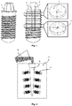
Figure 1 - exemplary schematic representation of a ceramic implant constituted by the main body (1) (a), before machining the inner channels, which will give rise to the internal electric circuit, and after machining the internal channels (b), which will give rise to the internal electric circuit, and local for housing the battery and electronic components or piezoelectric element on the top of the implant. Also shown are cuts with top views (c) of the electric wire system showing the circuit with a polarity, for example the negative (2) and with the other polarity, for example the positive (3). -
Figure 2 - exemplary schematic representation of a mould in plaster (4), containing the implants (1), and on which metal will be poured in the liquid state (6), which will flow through the feeding channel (5), and which will fill the electric circuit (2) and (3) inFig. 1 ) of the implants (1). -
Figure 3 - exemplary schematic representation of a mould, for example in graphite, constituted by a main body (8), and for example a lower part (10) and an upper part (9), where the implant (1) is placed with the channels which will constitute the electrical circuit and the location for the electronic component and battery, or piezoelectric component, already made, and where the powder or granules of the polymeric material, which is electrically conductive (7) are also placed. Pressure (11) and temperature (12), preferably in vacuum, is applied to fill the channels which will constitute the electric circuit by the polymeric composite. -
Figure 4 - exemplary schematic representation of a ceramic implant constituted by the main body, after machining and filling (14) of the internal channels that constitute the internal electric circuit, and example of electric fields (15) created, and battery and electronic components or piezoelectric element (13), and on which the crown (16) will be mounted. - The present disclosure consists in a dental implant, which is made up of a ceramic or ceramic composite (1) (
Figure 1 ), biocompatible, with an aesthetic function, and possibly bioactive, containing in its interior an electric circuit (2) (3) intended for providing electric fields to multiple points of the implant surface (15). This circuit is powered by a small battery that is housed on the top of the implant, in a possible abutment, or in the crown, together with a chip that coordinates the electrical stimuli (13), and / or alternatively by a piezoelectric component (13), which is actuated by the mastication force. - The present disclosure consists in a dental implant, which is made up of a ceramic or ceramic composite (1) (
Figure 1 ), biocompatible, with an aesthetic function, and possibly bioactive, containing in its interior an electric circuit (2) (3) which is intended for providing electric fields to multiple points of the implant surface (15). This circuit is powered by a small battery that is housed on the top of the implant, in a possible abutment, or in the crown, together with a chip that coordinates the electrical stimuli (13), and / or alternatively by a piezoelectric component (13), which is actuated by the mastication force. - In a preferred mode, the implant material consists of a ceramic based on zirconia, possibly containing alumina percentages or on alumina possibly containing zirconia. In addition to those, it may contain small percentages, for example from 1% (v / v) to 20% (v / v) of yttria, ceria, Magnesia, among other zirconia stabilizing materials, or even hydroxyapatite, βTCP, bioglass, among other bioactive and / or anti-bacterial materials.
- These materials, after being mixed, are pressed with pressures from 10 to 200MPa, preferably between 50 and 100 MPa. The blocks may then be pre-sintered at temperatures between 800 ° C and 1200 ° C, for periods between 0.5 and 5 hours. Alternatively, commercially available pre-sintered blocks, may be used.
- The pressed and / or pre-sintered blocks are then subjected to machining by mechanical route, with cutting tools, in numerically controlled equipments, for the creation of an housing area of the electronic and piezoelectronic components, and internal channels (2) (3), which will consist in the electric circuit. These channels will have a vertical distribution, along the main direction of the implant, and a radial one, at various implant heights. Alternatively, the laser ablation method for machining the holes that will consist in the internal channels may be used. The positive and negative electrical poles are in pairs (+ -) along the implant surface, in order to create multiple micro electric fields (15).
- The machined blocks will be followed by final sintering of the component, which will occur at temperatures between 1200 ° C and 1600 ° C, for periods between 1h and 5h, between periods of heating and cooling, which can last between 2 to 4 hours each with heating ramps of about 5 ° C / minute.
- After final sintering the implants will be subjected to filling of their internal channels with an electrically conductive material. In case the conductive material is metallic, for example silver or gold or platinum, among others that are biocompatible, these will be impregnated in the ceramic implant using the lost wax casting process. Briefly, the implants will be mounted on a feeding system (5), for example in the shape of a tree, in wax, the holes being filled with wax. Then the wax tree, which contains the implants, is immersed in plaster, inside a container giving rise to a plaster mould (4). Thereafter, this mould is subjected to a temperature of up to about 400 ° C for around 30 minutes, for extraction of the wax. Then the plaster mould is subjected to a baking cycle of the plaster in which it reaches about 800 ° C for a period of about 2 hours. Finally, the plaster mould is removed from the furnace and the liquid metal (6) which will consist in the electric circuit is poured into the interior of the mould (5), which contains the implants, filling the mould cavities and the internal holes of the implants (2) and (3).
- In the case where the conductive material is of polymer matrix, for example Polyether ether ketone (PEEK), or Poly (methyl methacrylate (PMMA), or other biocompatible polymer charged with a material that renders it electrically conductive, for example silver particles, carbon nanotubes, among others, this polymer matrix composite (7) is placed inside a mould, for example in graphite, for example constituted by a main body (8), a lower part (10), and an upper part (9), together with the implant (1) already containing the holes (2) and (3), and these are heated (12) until the polymeric composite reaches the liquid, pasty or semi-solid state and impregnates the holes. This impregnation is done due to the applied pressure (11), under vacuum, which causes the polymeric composite to flow into the implant holes, filling them completely.
- The implants will now have a geometry close to the final one, with the electric channels completely filled (14). They may possibly be subjected to machining for a final definition of geometry or thread. They may also be subjected to a polishing, or surface treatment by particle blasting, acid etching, laser, among others intended to create a surface texture suitable for a good bond to the bone tissues.
- At the top of the implant, or at the abutment, if the implant has it, it can then be mounted the signal processing station and the battery (13), or alternatively the piezoelectric component (13), which will give rise to the electric fields, distributed along the surface of the implant (15). The electric fields on the surface of the implant may be in the range of 5 to 100 mv. The crown (16) will be cemented or screwed over the implant body. In the event that the electronic system is made up of a controller and a battery, these (13) must operate while there are no mastication forces, and can then be removed and the electric fields become promoted by a piezoelectric component, which will actuate with the forces of mastication, throughout the entire life of the implant. The piezoelectric component consists of a biocompatible material, for example Barium Titanate BaTiO3, or niobate perovskite compounds, ((K, Na)NbO3), called KNN, and which generate an electric field when subjected to a deformation, due to a load such as that of mastication.
-
- [1]
US 8,374,697 B2 - Electrical dental screw implant - [2]
CN 103006343 B - Dental implant micro-electrical stimulation healing device - [3]
WO 2006043748 A1 - Apparatus for accelerating osseointergration - [4]
US 2003/0153965 A1 - Electrically conducting nanocomposite materials for biomedical applications. - [5]
US 5738521 A - Method for accelerating osseointegration of metal bone implants using electrical stimulation. - In one embodiment of the present disclosure the dental implant can comprise in its interior vertical channels (i.e., longitudinal channels along the dental implant defining an axis along its length) and radial ones that terminate in the form of holes in the lateral and lower surface of the implant and in which each channel comprises an electrically conductive material so as to promote multiple electric fields along the surface of the implant.
- In one embodiment, the implant may comprise an electronic component located on the abutment or crown consisting in a battery with a chip or in a piezoelectric component.
- In one embodiment, the electric fields range from 5 to 100 mv.
- In one embodiment, the electrically conductive material may be metal or polymer charged with particles or fibers that render the polymer electrically conductive.
- In one embodiment, the metal is selected from silver or gold or platinum or another biocompatible and electrically conductive metal.
- In one embodiment, the polymer may be selected from PEEK or PMMA or another biocompatible polymer.
- In one embodiment, the polymer may further comprise particles of silver or carbon nanotubes, or other biocompatible material that renders the polymer electrically conductive.
- In one embodiment, the implant may be of ceramic or ceramic composite material.
- In one embodiment, the implant may be of zirconia or alumina or a mixture thereof.
- In one embodiment, the implant may further comprise from 1 to 20% of yttria and / or ceria and / or Magnesia.
- In one embodiment, the implant may further comprise hydroxyapatite and / or TCP and / or bioglass.
- In one embodiment, the process for obtaining the implant may comprise the following steps:
- a. mixing the constituent ceramic materials of the implants and press them at a pressure between 10 and 200 MPa until a compact block is obtained;
- b. pre-sintering the obtained block;
- c. machining the blocks by milling in order to obtain the implants with the vertical and radial channels and the respective holes;
- d. sintering the blocks at a temperature between 1200 and 1600 ° C for a period of 1 to 5 hours.
- In one embodiment, the process may comprise channels which may be produced alternatively by laser ablation.
- In one embodiment, the lost wax casting process may comprise the following steps:
- a. placing the implants in the feeding system, tree-shaped, composed of wax;
- b. adding wax to the implant holes;
- c. immersing the implant-containing feeding system in plaster until a plaster mould is obtained;
- d. heating the mould to a temperature of 400 ° C for extraction of the wax;
- e. placing the mould in a furnace at 800 ° C for a period of 2 hours;
- f. removing the mould and pouring the metal into the plaster mould and into the holes of the implant.
- In one embodiment, the process of filling the inner channels with an electrically conductive polymer may comprise the following steps:
- a. The implant with the holes is placed inside a mould of graphite material or similar, wherein the mould is constituted by a main body, a lower part, and an upper part, together with the implant;
- b. The polymer is placed inside the mould and these are heated until the polymeric composite reaches the liquid, pasty or semi-solid state, and impregnates the holes.
- In one embodiment, the impregnation process of the holes may be made by pressure applied under vacuum, which causes the polymeric composite to flow into the orifices of the implants, filling them completely.
- The present disclosure is not, of course, in any way restricted to the embodiments described in this document and a person with average knowledge in the art may provide many possibilities of modifying it and replacing of technical characteristics by equivalent ones, depending on the requirements of each situation, as defined in the appended claims.
- The following claims further define preferred embodiments.
Claims (18)
- Dental implant defining an axis along its length, obtained from a sintered block, which comprises in its interior longitudinal and radial channels terminating in the form of holes in the surface of the implant and wherein each channel comprises an electrically conductive material for creating multiple electric fields along the surface of the implant.
- Dental implant according to the preceding claim, wherein the radial channels terminate in the form of holes in a lateral surface of the implant and the longitudinal channels terminate in the form of holes in a top surface of said implant.
- Dental implant according to any one of the preceding claims, wherein the radial channels terminate in the form of holes in a lateral surface, the respective electrically conductive material being connected in such a way as to alternate electrical poles along the surface of the implant.
- Dental implant according to any one of the preceding claims, wherein the longitudinal and radial channels terminate in the form of holes in the lateral and lower surfaces of the implant.
- Dental implant according to any one of the preceding claims, comprising an electronic component located on the abutment or crown, which comprises a battery having an integrated circuit, said chip, or a piezoelectric component.
- Dental implant according to the preceding claim, wherein the electronic component is configured so that said electric fields range between 5 and 100 mv.
- Dental implant according to any one of the preceding claims, wherein the electrically conductive material is metal or polymer charged with particles or fibers that render the polymer electrically conductive.
- Dental implant according to the preceding claim, wherein the metal is selected from silver or gold or platinum or other metal or metal alloy biocompatible and electrically conductive.
- Dental implant according to claim 7, wherein the polymer is selected from PEEK or PMMA or other biocompatible polymer.
- Dental implant according to the preceding claim, wherein the polymer further comprises silver particles or carbon nanotubes, or other biocompatible material that renders the polymer electrically conductive.
- Dental implant according to any one of the preceding claims, wherein the sintered implant block is of ceramic or ceramic based composite material.
- Dental implant according to the preceding claim, wherein said sintered implant block is of zirconia or alumina or a mixture thereof.
- Dental implant according to the preceding claim, wherein said implant comprises from 1 to 20% of yttria and / or ceria and / or Magnesia.
- Dental implant according to any one of the preceding claims, comprising hydroxyapatite and / or βTCP and / or bioglass.
- Process for obtaining the dental implant of any one of claims 1 to 14 comprising the following steps:mixing the constituent ceramic materials of the implant and press them at a pressure between 10 and 200 MPa until a compact block is obtained;pre-sintering the obtained block;machining the blocks by milling or by laser ablation in order to obtain the implants with the longitudinal and radial channels and the respective holes;sintering the blocks at a temperature between 1200 and 1600 ° C for a period of 1 to 5 hours.
- Process according to the preceding claim, wherein the lost wax casting process comprises the following steps:placing the implants in the feeding system, in the form of a tree, composed by wax;adding wax to the implant holes;immersing the implant-containing feeding system in plaster until a plaster mould in is obtained;heating the mould to a temperature of 400 ° C for extraction of the wax;placing the mould in a furnace at 800 ° C for a period of 2 hours;removing the mould and pouring the metal into the plaster mould and into the holes of the implant.
- Process according to any one of claims 15-16, wherein the filling of the inner channels by an electrically conductive polymer comprises the following steps:the implant with the holes is placed inside a mould of graphite material or similar in which the mould is comprised by a main body, a lower part, and an upper part, together with the implant;the polymer is placed inside the mould and these are heated until the polymeric composite reaches the liquid, pasty or semi-solid state, and impregnates the holes.
- Process according to anyone of claims 15-17, wherein the impregnation of the holes is done by applying pressure under vacuum, which causes the flow of the polymeric composite into the holes of the implants, in order to fill them.
Applications Claiming Priority (2)
| Application Number | Priority Date | Filing Date | Title |
|---|---|---|---|
| PT11037517 | 2017-10-26 | ||
| PCT/IB2018/058397 WO2019082154A1 (en) | 2017-10-26 | 2018-10-26 | Dental implant made of zirconia or alumina with healing electrical properties and its production method |
Publications (1)
| Publication Number | Publication Date |
|---|---|
| EP3701906A1 true EP3701906A1 (en) | 2020-09-02 |
Family
ID=64959378
Family Applications (1)
| Application Number | Title | Priority Date | Filing Date |
|---|---|---|---|
| EP18830295.4A Withdrawn EP3701906A1 (en) | 2017-10-26 | 2018-10-26 | Dental implant made of zirconia or alumina with healing electrical properties and its production method |
Country Status (6)
| Country | Link |
|---|---|
| US (1) | US20200306013A1 (en) |
| EP (1) | EP3701906A1 (en) |
| JP (1) | JP2021500189A (en) |
| CN (1) | CN111417358B (en) |
| BR (1) | BR112020008321B1 (en) |
| WO (1) | WO2019082154A1 (en) |
Families Citing this family (5)
| Publication number | Priority date | Publication date | Assignee | Title |
|---|---|---|---|---|
| CN116161956B (en) * | 2022-12-26 | 2024-01-16 | 北京大学口腔医学院 | Potassium sodium niobate/zirconia composite ceramic and preparation method and application thereof |
| USD1046155S1 (en) * | 2023-05-05 | 2024-10-08 | Daniel Domingue | Dental screw |
| CN117945754B (en) * | 2024-01-31 | 2024-09-06 | 江南大学 | Method for preparing ceramic dentures based on photocuring additive manufacturing and microwave sintering technology |
| PL450987A1 (en) * | 2025-01-18 | 2025-09-15 | Politechnika Częstochowska | Method of manufacturing and/or forming products from a material with a zirconium ceramic matrix |
| PL450986A1 (en) * | 2025-01-18 | 2025-09-15 | Politechnika Częstochowska | Method of manufacturing a material with a zirconium ceramic matrix and a bioactive part in the form of non-ionic elements from the platinum group |
Citations (1)
| Publication number | Priority date | Publication date | Assignee | Title |
|---|---|---|---|---|
| US6034295A (en) * | 1995-11-30 | 2000-03-07 | Christoph Rehberg | Implantable device having an internal electrode for stimulating growth of tissue |
Family Cites Families (17)
| Publication number | Priority date | Publication date | Assignee | Title |
|---|---|---|---|---|
| US5738521A (en) | 1996-07-19 | 1998-04-14 | Biolectron, Inc. | Method for accelerating osseointegration of metal bone implants using electrical stimulation |
| DE19928449C1 (en) * | 1999-06-23 | 2001-03-08 | Geot Ges Fuer Elektro Oseto Th | Bone screw with device for electrical stimulation |
| WO2001087193A1 (en) | 2000-05-16 | 2001-11-22 | Rensselaer Polytechnic Institute | Electrically conducting nanocomposite materials for biomedical applications |
| US20060078847A1 (en) * | 2000-09-29 | 2006-04-13 | Kwan Norman H | Dental implant system and additional methods of attachment |
| US6939135B2 (en) * | 2002-06-03 | 2005-09-06 | Schubert L. Sapian | Growth factor releasing biofunctional dental implant |
| IL160216A0 (en) * | 2004-02-04 | 2004-07-25 | Yosef Gross | Dental assembly |
| KR20060035112A (en) | 2004-10-21 | 2006-04-26 | 박성원 | Apparatus for accelerating osseointergration |
| US8374697B2 (en) | 2007-04-11 | 2013-02-12 | J. Lee Berger | Electrical dental screw implant |
| GB2476969A (en) * | 2010-01-18 | 2011-07-20 | Dental Devices Ltd Ab | Dental implant comprising a plurality of channels |
| KR101104191B1 (en) * | 2010-06-23 | 2012-01-09 | 이호도 | Apparatus and Method for Manufacturing Implants Using Amorphous Alloys |
| US9776014B2 (en) * | 2012-05-03 | 2017-10-03 | Magdent Ltd. | Bone enhancement device and method |
| CN103006343B (en) | 2012-12-31 | 2014-12-10 | 中国人民解放军总医院 | Dental implant micro-electrical stimulation healing device |
| CN203195781U (en) * | 2012-12-31 | 2013-09-18 | 中国人民解放军总医院 | Healing device for micro dental implant by micro electric field simulation |
| CN104207853A (en) * | 2013-06-04 | 2014-12-17 | 江苏创英医疗器械有限公司 | Electromagnetic stimulation dental implantation device |
| US10258436B2 (en) * | 2014-06-16 | 2019-04-16 | Saied Hemati | Method and system for transferring signals and materials between inside and outside body through oral cavity |
| CN104958116B (en) * | 2015-07-21 | 2017-10-13 | 上海市东方医院 | Voltage inductance answers implant denture |
| CN106859791B (en) * | 2017-02-21 | 2019-02-15 | 广州市健齿生物科技有限公司 | A two-stage dental implant |
-
2018
- 2018-10-26 BR BR112020008321-6A patent/BR112020008321B1/en not_active IP Right Cessation
- 2018-10-26 US US16/759,501 patent/US20200306013A1/en not_active Abandoned
- 2018-10-26 EP EP18830295.4A patent/EP3701906A1/en not_active Withdrawn
- 2018-10-26 WO PCT/IB2018/058397 patent/WO2019082154A1/en not_active Ceased
- 2018-10-26 JP JP2020523810A patent/JP2021500189A/en active Pending
- 2018-10-26 CN CN201880076629.0A patent/CN111417358B/en not_active Expired - Fee Related
Patent Citations (1)
| Publication number | Priority date | Publication date | Assignee | Title |
|---|---|---|---|---|
| US6034295A (en) * | 1995-11-30 | 2000-03-07 | Christoph Rehberg | Implantable device having an internal electrode for stimulating growth of tissue |
Also Published As
| Publication number | Publication date |
|---|---|
| BR112020008321A2 (en) | 2020-10-20 |
| JP2021500189A (en) | 2021-01-07 |
| WO2019082154A1 (en) | 2019-05-02 |
| US20200306013A1 (en) | 2020-10-01 |
| BR112020008321B1 (en) | 2023-01-17 |
| CN111417358A (en) | 2020-07-14 |
| CN111417358B (en) | 2022-04-15 |
Similar Documents
| Publication | Publication Date | Title |
|---|---|---|
| US20200306013A1 (en) | Dental implant made of zirconia or alumina with healing electrical properties and its production method | |
| Mehrali et al. | Dental implants from functionally graded materials | |
| CN105662621B (en) | A kind of porous dental implant and its manufacturing method of drug-carrying slow-released system | |
| JP2019503893A (en) | Method for additive manufacturing of 3D printed matter | |
| KR20190089719A (en) | A tooth implant, a stationary element that is automatically locked with a non-uniform porous structure, and a method of manufacturing the same | |
| CN105530888A (en) | Porous dental implant | |
| CN205698065U (en) | The porous tooth implant of drug-carrying slow-released system | |
| JP2013517024A (en) | Method for preparing a bone-integrating surface on a ceramic body | |
| EP1764061B1 (en) | Intraosseous dental implantation and method for making the same | |
| KR20130034283A (en) | Manufacturing method for porous implant and porous implant produced thereof | |
| JP2740071B2 (en) | Method for producing sintered metal body for implant | |
| JP7202023B2 (en) | Dental implant with electrical stimulation system and manufacturing method thereof | |
| KR101095909B1 (en) | Artificial bone-induced artificial bone and its manufacturing method | |
| KR20140014614A (en) | Dental block and method for manufacturing the same | |
| KR102187414B1 (en) | Zirconia Abutment Product Method | |
| KR102687970B1 (en) | Method for producing porous medical implant | |
| US11291612B2 (en) | Injectable hybrid cement for dental implants and methods of manufacture thereof | |
| JP2001011509A (en) | Porous calcium phosphate compound / metal composite sintered body and method for producing the same | |
| CN108785750B (en) | A kind of hydroxyapatite gradient structure coating and preparation method thereof | |
| JP4010774B2 (en) | Calcium phosphate-synthetic resin composite for biomaterial and method for producing the same | |
| DE102006036663B3 (en) | Process for producing a ceramic shaped body by means of electrophoresis and subsequent sintering and its use | |
| Tourrel et al. | Implantable Technologies in Cochlear Implants: Mechanics, Materials, and Electrochemistry | |
| KR101413541B1 (en) | Method for manufacturing a three-dimensional scaffold | |
| JPH0690972A (en) | Bone implant and its production | |
| JP2001089227A (en) | Porous calcium phosphate compound/metal composite sintered compact and its production method |
Legal Events
| Date | Code | Title | Description |
|---|---|---|---|
| STAA | Information on the status of an ep patent application or granted ep patent |
Free format text: STATUS: UNKNOWN |
|
| STAA | Information on the status of an ep patent application or granted ep patent |
Free format text: STATUS: THE INTERNATIONAL PUBLICATION HAS BEEN MADE |
|
| PUAI | Public reference made under article 153(3) epc to a published international application that has entered the european phase |
Free format text: ORIGINAL CODE: 0009012 |
|
| STAA | Information on the status of an ep patent application or granted ep patent |
Free format text: STATUS: REQUEST FOR EXAMINATION WAS MADE |
|
| 17P | Request for examination filed |
Effective date: 20200512 |
|
| AK | Designated contracting states |
Kind code of ref document: A1 Designated state(s): AL AT BE BG CH CY CZ DE DK EE ES FI FR GB GR HR HU IE IS IT LI LT LU LV MC MK MT NL NO PL PT RO RS SE SI SK SM TR |
|
| AX | Request for extension of the european patent |
Extension state: BA ME |
|
| DAV | Request for validation of the european patent (deleted) | ||
| DAX | Request for extension of the european patent (deleted) | ||
| STAA | Information on the status of an ep patent application or granted ep patent |
Free format text: STATUS: EXAMINATION IS IN PROGRESS |
|
| 17Q | First examination report despatched |
Effective date: 20220302 |
|
| GRAP | Despatch of communication of intention to grant a patent |
Free format text: ORIGINAL CODE: EPIDOSNIGR1 |
|
| STAA | Information on the status of an ep patent application or granted ep patent |
Free format text: STATUS: GRANT OF PATENT IS INTENDED |
|
| INTG | Intention to grant announced |
Effective date: 20230509 |
|
| GRAS | Grant fee paid |
Free format text: ORIGINAL CODE: EPIDOSNIGR3 |
|
| STAA | Information on the status of an ep patent application or granted ep patent |
Free format text: STATUS: THE APPLICATION IS DEEMED TO BE WITHDRAWN |
|
| 18D | Application deemed to be withdrawn |
Effective date: 20240501 |