EP3701891A1 - Active traction device and control method therefor - Google Patents
Active traction device and control method therefor Download PDFInfo
- Publication number
- EP3701891A1 EP3701891A1 EP18871730.0A EP18871730A EP3701891A1 EP 3701891 A1 EP3701891 A1 EP 3701891A1 EP 18871730 A EP18871730 A EP 18871730A EP 3701891 A1 EP3701891 A1 EP 3701891A1
- Authority
- EP
- European Patent Office
- Prior art keywords
- retracting
- force
- shaft
- user
- controller
- Prior art date
- Legal status (The legal status is an assumption and is not a legal conclusion. Google has not performed a legal analysis and makes no representation as to the accuracy of the status listed.)
- Granted
Links
Images








Classifications
-
- A—HUMAN NECESSITIES
- A61—MEDICAL OR VETERINARY SCIENCE; HYGIENE
- A61B—DIAGNOSIS; SURGERY; IDENTIFICATION
- A61B17/00—Surgical instruments, devices or methods
- A61B17/56—Surgical instruments or methods for treatment of bones or joints; Devices specially adapted therefor
- A61B17/58—Surgical instruments or methods for treatment of bones or joints; Devices specially adapted therefor for osteosynthesis, e.g. bone plates, screws or setting implements
- A61B17/88—Osteosynthesis instruments; Methods or means for implanting or extracting internal or external fixation devices
- A61B17/8866—Osteosynthesis instruments; Methods or means for implanting or extracting internal or external fixation devices for gripping or pushing bones, e.g. approximators
-
- A—HUMAN NECESSITIES
- A61—MEDICAL OR VETERINARY SCIENCE; HYGIENE
- A61B—DIAGNOSIS; SURGERY; IDENTIFICATION
- A61B17/00—Surgical instruments, devices or methods
- A61B17/56—Surgical instruments or methods for treatment of bones or joints; Devices specially adapted therefor
- A61B17/58—Surgical instruments or methods for treatment of bones or joints; Devices specially adapted therefor for osteosynthesis, e.g. bone plates, screws or setting implements
- A61B17/60—Surgical instruments or methods for treatment of bones or joints; Devices specially adapted therefor for osteosynthesis, e.g. bone plates, screws or setting implements for external osteosynthesis, e.g. distractors, contractors
- A61B17/64—Devices extending alongside the bones to be positioned
-
- A—HUMAN NECESSITIES
- A61—MEDICAL OR VETERINARY SCIENCE; HYGIENE
- A61B—DIAGNOSIS; SURGERY; IDENTIFICATION
- A61B17/00—Surgical instruments, devices or methods
- A61B17/56—Surgical instruments or methods for treatment of bones or joints; Devices specially adapted therefor
- A61B17/58—Surgical instruments or methods for treatment of bones or joints; Devices specially adapted therefor for osteosynthesis, e.g. bone plates, screws or setting implements
- A61B17/60—Surgical instruments or methods for treatment of bones or joints; Devices specially adapted therefor for osteosynthesis, e.g. bone plates, screws or setting implements for external osteosynthesis, e.g. distractors, contractors
- A61B17/66—Alignment, compression or distraction mechanisms
-
- A—HUMAN NECESSITIES
- A61—MEDICAL OR VETERINARY SCIENCE; HYGIENE
- A61B—DIAGNOSIS; SURGERY; IDENTIFICATION
- A61B90/00—Instruments, implements or accessories specially adapted for surgery or diagnosis and not covered by any of the groups A61B1/00 - A61B50/00, e.g. for luxation treatment or for protecting wound edges
- A61B90/06—Measuring instruments not otherwise provided for
-
- G—PHYSICS
- G01—MEASURING; TESTING
- G01D—MEASURING NOT SPECIALLY ADAPTED FOR A SPECIFIC VARIABLE; ARRANGEMENTS FOR MEASURING TWO OR MORE VARIABLES NOT COVERED IN A SINGLE OTHER SUBCLASS; TARIFF METERING APPARATUS; MEASURING OR TESTING NOT OTHERWISE PROVIDED FOR
- G01D21/00—Measuring or testing not otherwise provided for
- G01D21/02—Measuring two or more variables by means not covered by a single other subclass
-
- A—HUMAN NECESSITIES
- A61—MEDICAL OR VETERINARY SCIENCE; HYGIENE
- A61B—DIAGNOSIS; SURGERY; IDENTIFICATION
- A61B17/00—Surgical instruments, devices or methods
- A61B2017/00017—Electrical control of surgical instruments
- A61B2017/00022—Sensing or detecting at the treatment site
-
- A—HUMAN NECESSITIES
- A61—MEDICAL OR VETERINARY SCIENCE; HYGIENE
- A61B—DIAGNOSIS; SURGERY; IDENTIFICATION
- A61B17/00—Surgical instruments, devices or methods
- A61B2017/00017—Electrical control of surgical instruments
- A61B2017/00022—Sensing or detecting at the treatment site
- A61B2017/00075—Motion
-
- A—HUMAN NECESSITIES
- A61—MEDICAL OR VETERINARY SCIENCE; HYGIENE
- A61B—DIAGNOSIS; SURGERY; IDENTIFICATION
- A61B17/00—Surgical instruments, devices or methods
- A61B2017/00017—Electrical control of surgical instruments
- A61B2017/00199—Electrical control of surgical instruments with a console, e.g. a control panel with a display
-
- A—HUMAN NECESSITIES
- A61—MEDICAL OR VETERINARY SCIENCE; HYGIENE
- A61B—DIAGNOSIS; SURGERY; IDENTIFICATION
- A61B17/00—Surgical instruments, devices or methods
- A61B2017/00017—Electrical control of surgical instruments
- A61B2017/00212—Electrical control of surgical instruments using remote controls
-
- A—HUMAN NECESSITIES
- A61—MEDICAL OR VETERINARY SCIENCE; HYGIENE
- A61B—DIAGNOSIS; SURGERY; IDENTIFICATION
- A61B17/00—Surgical instruments, devices or methods
- A61B2017/00367—Details of actuation of instruments, e.g. relations between pushing buttons, or the like, and activation of the tool, working tip, or the like
- A61B2017/00398—Details of actuation of instruments, e.g. relations between pushing buttons, or the like, and activation of the tool, working tip, or the like using powered actuators, e.g. stepper motors, solenoids
-
- A—HUMAN NECESSITIES
- A61—MEDICAL OR VETERINARY SCIENCE; HYGIENE
- A61B—DIAGNOSIS; SURGERY; IDENTIFICATION
- A61B90/00—Instruments, implements or accessories specially adapted for surgery or diagnosis and not covered by any of the groups A61B1/00 - A61B50/00, e.g. for luxation treatment or for protecting wound edges
- A61B90/06—Measuring instruments not otherwise provided for
- A61B2090/061—Measuring instruments not otherwise provided for for measuring dimensions, e.g. length
-
- A—HUMAN NECESSITIES
- A61—MEDICAL OR VETERINARY SCIENCE; HYGIENE
- A61B—DIAGNOSIS; SURGERY; IDENTIFICATION
- A61B90/00—Instruments, implements or accessories specially adapted for surgery or diagnosis and not covered by any of the groups A61B1/00 - A61B50/00, e.g. for luxation treatment or for protecting wound edges
- A61B90/06—Measuring instruments not otherwise provided for
- A61B2090/064—Measuring instruments not otherwise provided for for measuring force, pressure or mechanical tension
-
- A—HUMAN NECESSITIES
- A61—MEDICAL OR VETERINARY SCIENCE; HYGIENE
- A61B—DIAGNOSIS; SURGERY; IDENTIFICATION
- A61B90/00—Instruments, implements or accessories specially adapted for surgery or diagnosis and not covered by any of the groups A61B1/00 - A61B50/00, e.g. for luxation treatment or for protecting wound edges
- A61B90/36—Image-producing devices or illumination devices not otherwise provided for
- A61B90/37—Surgical systems with images on a monitor during operation
- A61B2090/376—Surgical systems with images on a monitor during operation using X-rays, e.g. fluoroscopy
Definitions
- This disclosure relates to an active retractor and a control method thereof, and more particularly, to an active retractor implemented to detect a stress state of a fractured area during fracture reposition and compensate for a required retracting force, and a control method thereof.
- the use of metal plates or metal tablets to fix fractured bones is commonplace.
- the metal plate is used by a surgeon to stabilize, correct or align the bone of a patient.
- the metal plate is typically fastened to bone fragments by a plurality of fastening units such as screws installed through holes formed in the plate.
- fractured bone fragments are contracted by the muscles, and bone fragments located far away must be properly retracted to align the bone fragments to their proper positions. After being retracting the bone fragments to the original positions, fracture reposition is performed by finely manipulating the bone fragments and fixed using a metal plate or a metal nail.
- a conventional retractor just retracts bone fragments by an attractive force or a mechanical configuration and then fix the bone fragments.
- the retraction is provided only at a fixed location against a stress change of the fractured area that is generated during a fracture reposition process, so there is a limit in providing a retracting force necessary for the intention of a surgical operator.
- This disclosure is directed to providing an active retractor, which includes a sensor for a stress state of a fractured area, a controller and an actuator to provide a constant retracting force required for a fractured area in real time, and a control method thereof.
- an active retractor comprising: a retracting shaft configured to fasten fractured bone fragments of a patient and retract the fractured bone fragments in a front and rear direction; a measuring device connected and installed to the retracting shaft to measure a retracting location or a retracting force of the retracting shaft; an actuator connected and installed to the retracting shaft to drive the retracting shaft in the front and rear direction; a driver configured to supply a power required for driving the actuator to the actuator according to a driving control signal; and a controller configured to generate a driving control signal, which is required for the driver to supply a power, by comparing a retracting request signal input from a user with a measured value transmitted from the measuring device and transmit the driving control signal to the driver.
- the measuring device may include: a retracting force measuring sensor connected and installed to the retracting shaft to measure a tensile force or a compressive force of the retracting shaft and then generate tensile force information or compressive force information corresponding thereto to be transmitted to the controller; and a displacement measuring sensor connected and installed to the retracting shaft to measure a moved location of the retracting shaft and generate location information corresponding thereto to be transmitted to the controller.
- the controller may include: a user interface unit configured to display number information and graphic information required for manipulation and receive the retracting request signal from the user; and a driving control unit configured to generate the driving control signal, which is required for the driver to supply a power, by comparing the retracting request signal received from the user interface unit with the measured value transmitted from the measuring device and transmit the driving control signal to the driver.
- the user interface unit may receive a retracting force, a retracting speed, a retracting location, a retracting start/stop, an emergency stop, or postural adjustment of a retracting instrument.
- the user interface unit may receive from the user a retracting distance mode in which a bone fragment is retracted to a retracting location set by the user and then the retracted bone fragment is fixed or a retracting force mode in which a bone fragment is retracted while constantly maintaining a stress of the bone fragment to a retracting force set by the user.
- the driving control unit may generate retracting force information corresponding to the tensile force information or the compressive force information transmitted from the retracting force measuring sensor and transmit the retracting force information to the user interface unit.
- the driving control unit may generate current location information or speed information of the retracting shaft corresponding to the location information transmitted from the displacement measuring sensor and transmit the current location information or speed information to the user interface unit.
- the driving control signal may be a control signal about a retracting speed, a retracting location or a retracting force of the retracting shaft in a digital or analog form.
- the active retractor may further comprise a foothold switch or a remote controller located within a work area of the user to receive a retracting request signal or an operation mode from the user and transmit the retracting request signal or the operation mode to the controller.
- the active retractor may further comprise a location display device formed at one side of the actuator to display a driving location of the retracting shaft in real time.
- the active retractor may further comprise a laser guide formed at one side of the actuator to guide a retracting direction and an aligning direction of a fractured area of a patient.
- the active retractor may further comprise a retracting arm mounted and installed to the actuator to operate in the front and rear direction, one side of the retracting shaft being inserted in and fastened to the retracting arm so that the retracting shaft is driven in the front and rear direction by the retracting arm, the retracting arm releasing the fastening of the retracting shaft when a force equal to or greater than a preset force is applied thereto so that the retracting shaft is released.
- a active retractor control method comprising: by a controller, receiving and setting a retracting request signal from a user; by the controller, allowing the user to select a retracting mode; by an actuator connected and installed to a retracting shaft, driving the retracting shaft in a front and rear direction under the control of the controller; by a measuring device connected and installed to a retracting shaft, measuring a retracting speed, a retracting location or a retracting force of the retracting shaft and generating a measured value corresponding thereto to be transmitted to the controller; by the controller, comparing the measured value transmitted from the measuring device with the retracting request signal received from the user; and by the controller, completing the retracting process and maintaining the retracting shaft in a fixed state when the measured value reaches the retracting request signal.
- the active retractor control method may further comprise, before said receiving and setting a retracting request signal, photographing a fractured bone fragment of a patient as a fluoroscopy image and checking a distance by which the fractured bone fragment is to be retracted.
- the user in said allowing the user to select a retracting mode, may be allowed to select a retracting distance mode in which a bone fragment is retracted to a set retracting location and then the retracted bone fragment is fixed or a retracting force mode in which a bone fragment is retracted while constantly maintaining a stress of the bone fragment to a set retracting force.
- the retracting mode in progress may be temporarily stopped and the bone fragment may be retracted in the other retracting mode.
- the active retractor control method may further comprise, by the controller, emergently stopping the driving of the retracting shaft, when the retracting force measured in said generating a measured value and transmitting to the controller exceeds a limit retracting force.
- the active retractor control method may further comprise adjusting the retracting location or the retracting force of the retracting shaft, when the measured value fails to reach the retracting request signal, after said comparing.
- said driving may include: by the controller, generating a driving control signal required for a driver to supply a power to the actuator and transmitting the driving control signal to the driver; by the driver, supplying a power required for driving the actuator to the actuator according to the driving control signal transmitted from the controller; and by the actuator, driving the retracting shaft in the front and rear direction according to the power supplied from the driver.
- the active retractor includes a sensor for a stress state of a fractured area, a controller and an actuator and thus may provide a constant retracting force required for a fractured area in real time, and a control method thereof.
- FIG. 1 is a diagram showing a schematic configuration of an active retractor according to an embodiment of the present disclosure.
- an active retractor 10 includes a retracting shaft 100, a measuring device 200, an actuator 300, a driver 400, and a controller 500.
- the retracting shaft 100 is connected and installed to the actuator 300 and is fastened to a fractured bone fragment of a patient and retracts the fractured bone fragment in a front and rear direction.
- the retracting shaft 100 may include a gripping means provided at one side terminal thereof to grip a bone fragment of the patient.
- the measuring device 200 is connected and installed to the retracting shaft 100 to measure a retracting location or a retracting force of the retracting shaft 100.
- the measuring device 200 includes a retracting force measuring sensor 210 and a displacement measuring sensor 220.
- the retracting force measuring sensor 210 is directly connected and installed to the retracting shaft 100 and measures a tensile force or a compressive force of the retracting shaft 100 and generates corresponding tensile force information or compressive force information corresponding thereto. Also, the retracting force measuring sensor 210 transmits the corresponding tensile force information or the corresponding compressive force information to the controller 500.
- a load cell or a pressure sensor may be used directly.
- the retracting force measuring sensor 210 may use a principle of measuring displacement generated by an acting force.
- the displacement measuring sensor 220 is directly connected and installed to the retracting shaft 100, measures a moved location of the retracting shaft 100, generates location information corresponding thereto, and transmits the generated location information to the controller 500.
- an optical/magnetic absolute encoder As a sensor that may be applied as the displacement measuring sensor 220, an optical/magnetic absolute encoder, an optical/magnetic incremental encoder, or a photo interrupt or a hall switch may be applied to a required position.
- the actuator 300 is connected and installed to the retracting shaft 100, receives a power from the driver 400, and drives the retracting shaft 100 in the front and rear direction in response to the supplied power.
- the actuator 300 corresponds to a driving unit that generates a linear movement and a retracting force for moving a bone fragment to a location necessary for retracting, and may include a reducer capable of adjusting speed and torque according to an electric control of the driver 400 and a ball screw for converting rotational movement of the reducer into linear movement.
- the driver 400 receives a driving control signal from the controller 500 and supplies a power required for driving the actuator 300 to the actuator 300 according to the received driving control signal.
- the driver 400 supplies a power required for driving the actuator 300 to the actuator 300 according to the control signal of the controller 500, and the driver 400 may be a three-phase inverter including a speed and torque controller or a power switch in the form of a pulse width modulation (PWM) control.
- PWM pulse width modulation
- the controller 500 compares the retracting request signal input from the user with a measured value transmitted from the measuring device 200, generates a driving control signal, which is required for the driver 400 to supply a power, corresponding to the compared value, and transmits the corresponding driving control signal to the driver 400.
- the controller 500 may output the control signal required for the driver 400 by comparing the retracting request signal set by the user to follow the retracting force, the retracting location and the retracting speed with the measured values of the retracting force measuring sensor 210 and the displacement measuring sensor 220.
- the controller 500 may calculate information about a stress of the fractured area measured by the retracting force measuring sensor 210 and calculate a speed by differentiating the measured position with respect to the current position and time of the retracting shaft 100 measured by the displacement measuring sensor 220. Also, the controller 500 may compare the information calculated by each sensor with user setting formation and transmit a driving control signal to the driver 400 to maintain the necessary retracting force and the necessary retracting location.
- the driving control signal transmitted to the driver 400 is a control signal about speed, location and retracting force and may be in a digital or analog form.
- the active retractor 10 configured as above may further include a display device 310 and a laser guide 320 (see FIG. 6 ).
- the display device 310 is formed at one side of the actuator 300, and displays a driving location of the retracting shaft 100 in real time or a maximum contraction/relaxation state of a pulling rod of the retracting shaft 100.
- the display device 310 displays the maximum extension state of the retracting shaft 100 as "Full forward”, displays the maximum contraction state as "Full back”, and divides the state into a plurality of stages so that the user may visually recognize the retracting state of the retracting shaft 100 in an easy way.
- the laser guide 320 is formed at one side of the actuator 300 and may irradiate a guide laser to guide a retracting direction and an alignment direction of the fractured area of the patient.
- the active retractor 10 configured as above includes a measuring device 200 capable of detecting a stress state of the fractured area during fracture reposition, a controller 500 and an actuator 300, thereby providing a constant retracting force necessary for the fractured area in real time.
- FIG. 3 is a control block diagram for illustrating the controller depicted in FIG. 1 .
- the controller 500 includes a user interface unit 510 and a driving control unit 520.
- the user interface unit 510 displays number information and graphic information necessary for manipulation, receives a retracting request signal from the user, and transmits the received retracting request signal to the driving control unit 520.
- the user interface unit 510 may implement a user interface in consideration of the retractor characteristics and fracture reposition procedure.
- the user interface unit 510 implements an environment that enables the user to perform safe manipulation without knowing the manual and provides a step-by-step method in which the setting and check items for each step are displayed and confirmed by the user, and 2) in a skill mode 512, the user interface unit 510 provides only a basic panel that displays various setting values and a state of the driver to support a rapid use environment for experienced users.
- the user interface unit 510 is a device for displaying numerical information and graphic information necessary for retractor operation, and may utilize a GUI program based on a mechanical electrical contact or a touch screen.
- a main user display (output) function of the user interface unit 510 may display a retracting force, a retracting speed and a retracting location currently measured as well as various alarms such as a retracting upper limit, a retracting lower limit and a retracting-executing mark.
- a main user input function of the user interface unit 510 may support a manipulation panel for retracting force setting input, retracting speed setting input, retracting location setting input, retracting start/stop, emergency stop, and retracting instrument postural adjustment.
- the user interface unit 510 may have a simple display form in which necessary setting inputs and displays are listed on the screen for user convenience and safe use, or a manual (wizard) display form in which need-to-know items or medical information important for the retractor operation of the user are displayed sequentially suitable for the surgical operation procedure so as to be checked by the user.
- the user interface unit 510 is a hardware interface for user convenience.
- a foothold switch 700 and a remote controller 600 may be provided in the work area of the user.
- the driving control unit 520 receives the retracting request signal from the user interface unit 510, receives the measured value from the measuring device 200, compares the received retracting request signal with the measured value, and generates a driving control signal required for power supply to the driver 400 corresponding value to the compared value, and transmits the corresponding generated driving control signal to the driver 400.
- the user interface unit 510 may receive a retracting force, a retracting speed, a retracting location, a retracting start/stop, an emergency stop, or postural adjustment of the retracting instrument.
- the user interface unit 510 may receive from the user a retracting distance mode in which a bone fragment is retracted to a retracting location set by the user and then the retracted bone fragment is fixed, or a retracting force mode in which a bone fragment is retracted while maintaining the stress of the bone fragment to a retracting force set by the user.
- the retracting distance mode may be utilized when a bone fragment is always fixed at a constant position after fracture reposition is completed since the bone fragment is moved and then the retraction is fixed.
- the retracting force mode retraction is performed while maintaining the stress of the bone fragment as much as the retracting force set by the user, so the retracting force mode may be utilized when stable relaxation minimizing muscle tissue damage in an over-rap state caused by muscle contraction on the fractured area is required before fracture reposition or when the fracture reposition is required.
- the retractor compensates for the stress of the fractured area on the influence of the attraction caused by the invention of a surgical operator, thereby reducing the burden on the surgical operator and enabling a stable fracture reposition procedure.
- the foot of the patient is retracted by a preset distance (for example, 5 cm to 20 cm) and fixed according to the present disclosure, which allows the surgical operator to avoid unnecessary forces and to make precise retraction, thereby ensuring the accuracy and stability of the surgical operation.
- a preset distance for example, 5 cm to 20 cm
- the driving control unit 520 may generate retracting force information corresponding to the tensile force information or the compressive force information transmitted from the retracting force measuring sensor 210, and transmit the retracting force information to the user interface unit 510.
- the driving control unit 520 may generate current location information or speed information of the retracting shaft 100 corresponding to the location information transmitted from the displacement measuring sensor 220 and transmit the generated information to the user interface unit 510.
- the driving control signal is a control signal for retracting speed, retracting location or retracting force of the retracting shaft 100 and may be a digital or analog signal.
- the driving control unit 520 may calculate the information on the stress of the fractured area measured by the retracting force measuring sensor 210 and transmit the information to the user interface unit 510, and may calculate the speed by differentiating the location measured with respect to the current location and time of the retracting shaft 100 measured by the displacement measuring sensor 220 and transmit the calculated location and speed information to the user interface unit 510.
- the driving control unit 520 may transmit the measured values measured by the retracting force measuring sensor 210 and the displacement measuring sensor 220 to the user interface unit 510 to be displayed on the user interface unit 510.
- FIG. 5 is a diagram showing a schematic configuration of an active retractor according to an embodiment of the present disclosure.
- the active retractor 20 includes a retracting shaft 100, a measuring device 200, an actuator 300, a driver 400, a controller 500, a foothold switch 700, and a remote controller 600.
- the retracting shaft 100, the measuring device 200, the actuator 300, the driver 400 and the controller 500 are the same as the components of shown in FIG. 1 and thus will not described in detail here.
- the remote controller 600 is located within the work area of the user, and receives the retracting request signal (for example, a request signal for changing the location of the retracting shaft 100 or increasing or decreasing the retracting force of the retracting shaft 100) or an operation mode from the user and transmits the corresponding retracting request signal to the controller 500 through wired or wireless communication.
- the retracting request signal for example, a request signal for changing the location of the retracting shaft 100 or increasing or decreasing the retracting force of the retracting shaft 100
- the foothold switch 700 is located within the work area of the user. If the user is not able to use both hands for reasons such as surgery, the foothold switch 700 receives a retracting request signal (for example, a request signal for changing the location of the retracting shaft 100 or increasing or decreasing the retracting force of the retracting shaft 100) or an operation mode and transmits the same to the controller 500.
- a retracting request signal for example, a request signal for changing the location of the retracting shaft 100 or increasing or decreasing the retracting force of the retracting shaft 100
- FIG. 7 is a diagram showing a schematic configuration of an active retractor according to an embodiment of the present disclosure.
- the active retractor 30 includes a retracting shaft 100, a measuring device 200, an actuator 300, a driver 400, a controller 500, and a retracting arm 800.
- the retracting shaft 100, the measuring device 200, the actuator 300, the driver 400 and the controller 500 are the same as the components of FIG. 1 and thus will not be described in detail here.
- the retracting arm 800 is mounted and installed to the actuator 300 and is driven in the front and rear direction corresponding to the driving of the actuator 300. Also, one side of the retracting shaft 100 is inserted into the retracting arm 800 and fastened thereto so that the retracting shaft 100 is driven in the front and rear direction, and the fastening is released if a force greater than a preset force is applied thereto, to relax the retracting shaft 100.
- the active retractor 30 configured as above implements a double safety device as a stabilizer of a mechanical configuration independent from an electrical device, and it is possible to prevent a safety accident that an excessive force is transferred to an affected part during the retracting process.
- FIG. 8 is a diagram for illustrating a retracting arm depicted in FIG. 7 .
- the retracting arm 800 includes a relaxation damper 810 and a load limiter 820.
- the relaxation damper 810 is mounted and installed to the actuator 300, and one side of the retracting shaft 100 is inserted into an insert groove formed therein. Also, when the retracting shaft 100 is released and relaxed from the insert groove, the relaxation damper 810 absorbs a part of the transferred force.
- the load limiter 820 is mounted and installed to an open one side of the relaxation damper 810 and fastens the retracting shaft 100. When a force equal to or greater than a preset force is supplied thereto from the actuator 300, the load limiter 820 releases the fastening.
- the actuator 300 and the retracting arm 800 serving as a safety device are moved together to transmit the retracting force of the actuator 300.
- the load limiter 820 fastened to the retracting shaft 100 releases the fastening to separate the retracting shaft 100 from the relaxation damper 810, and the relaxation damper 810 may slowly perform a relaxation operation with a maximum stroke (a maximum stroke of the relaxation damper 810) by itself.
- FIG. 10 is a diagram for illustrating a relaxation damper depicted in FIG. 8 .
- the relaxation damper 810 includes a piston body 811, a piston unit 812, and a relaxation elastic unit 813.
- the piston body 811 has an insert groove formed therein so that one side of the retracting shaft 100 is inserted therein, and the piston body 811 is connected and installed to the actuator 300.
- the piston unit 812 is mounted and installed to one end of the retracting shaft 100 and slides in the front and rear direction in the insert groove of the piston body 811.
- the relaxation elastic unit 813 is inserted between the insert groove of the piston body 811 and the piston unit 812 to press the piston unit 812 in one direction.
- the relaxation elastic unit 813 may be implemented as a spring, a solid or a fluid.
- the relaxation damper 810 configured as above, if the retracting shaft 100 comes into a freely movable state without restraint as shown in FIG. 13(B) as the load limiter 820 is loosened, the piston unit 812 is prevented from suddenly sliding in the front and rear direction in the insert groove of the piston body 811 due to the elastic force of the relaxation elastic unit 813, so the relaxation damper 810 may slowly perform a relaxation operation with a maximum stroke (a maximum stroke of the relaxation damper 810) by itself.
- FIG. 11 is a diagram for illustrating a load limiter depicted in FIG. 8 .
- the load limiter 820 includes a housing 821, a plurality of fastening units 822, a pressing unit 823, an elastic unit 824, a supporting unit 825, and a load adjusting unit 826.
- the housing 821 is mounted and installed to one side of the relaxation damper 810, so that the plurality of fastening unit 822, the pressing unit 823, the elastic unit 824, the supporting unit 825 and the load adjusting unit 826 are accommodated in a space formed therein.
- the housing 821 may form a funnel-shaped inclined surface 827 at an inner portion thereof (see FIG. 12 ).
- the housing 821 may have a fastening thread 828 formed at an inlet portion thereof to fasten the insert thread 8263 (see FIG. 12 ).
- the fastening unit 822 is fastened to the fastening groove 110 formed at an outer surface of the retracting shaft 100.
- the fastening unit 822 may be formed in a spherical shape or a wedge shape.
- the fastening unit 822 may move into the housing 821 along the inclined surface 827 to fasten the fastening groove 110 as the distance from another fastening unit 822 decreases.
- the pressing unit 823 is connected and installed to the other side of the fastening unit 822 to press the fastening unit 822 into the housing 821.
- the elastic unit 824 is connected and installed to the other side of the pressing unit 823 to press the pressing unit 823 into the housing 821 by an elastic force.
- the supporting unit 825 is inserted into the other side of the elastic unit 824 to support the elastic unit 824.
- the load adjusting unit 826 is mounted and installed to one open side of the housing 821 to adjust the insertion location of the supporting unit 825.
- the load limiter 820 configured as above may release the fastening unit 822 when the force supplied from the actuator 300 is greater than the fastening force of the fastening unit 822 that fastens the fastening groove 110.
- the load limiter 820 configured as above adjusts the fastening force of the fastening unit 822 placed in the fastening groove 110 of the retracting shaft 100 by the tension of the elastic unit 824, to release the fastening unit 822 when the force applied to the retracting shaft 100 is greater than the tightening force, thereby preventing an excessive force from being transferred to the retracting shaft 100.
- the fastening of the load limiter 820 in a normal state in which a force smaller than the force set by the retracting shaft 100 is transmitted, the fastening of the load limiter 820 is not released from the retracting shaft 100 as shown in FIG. 13(A) and thus may move together with the relaxation damper 810 in the left and right direction.
- the fastening unit 822 moves along the fastening groove 110 of the retracting shaft 100 and is pushed by the compressive force of the elastic unit 824 to deviate from the fastening groove 110 of the retracting shaft 100, so the fastening unit 822 is released from the retracting shaft 100 as shown in FIG. 13(B) to deviate from the binding force of the fastening unit 822.
- the retracting force transmitted through the fastening unit 822 is interrupted and the retracting shaft 100 comes into a freely movable state without restraint.
- the relaxation damper 810 is provided thereto to prevent the sudden movement.
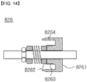
- FIG. 14 is a diagram for illustrating a load adjusting unit depicted in FIG. 11 .
- the load adjusting unit 826 includes a handle means 8261, an adjustment means 8262 and a cover means 8264.
- the handle means 8261 has an adjustment means 8262 formed on one side and allows the user to grip and rotate the handle means 8261 by hand.
- the adjustment means 8262 is formed at one side of the handle means 8261 to adjust the insertion location of the supporting unit 825 while being inserted into or separated from the housing 821 in response to the rotation direction of the handle means 8261.
- the adjustment means 8262 may have an insert thread 8263 formed at an outer side so as to be fastened to the housing 821.
- the cover means 8264 extends from the handle means 8261 toward the housing 821 to cover the open one side of the housing 821.
- the cover means 8264 may have an uneven portion formed at an outer surface thereof to form a frictional force when being gripped by hand of the user.
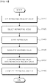
- FIG. 15 is a flowchart for illustrating an active retractor control method according to an embodiment of the present disclosure.
- the controller 500 receives and sets a retracting request signal from a user (S1410).
- the controller 500 allows the user to select a retracting mode (S1420).
- the retracting distance mode in which a bone fragment location is moved by the set retracting location and then the retracted bone fragment location is fixed ( FIG. 16A , in the case of the "retracting distance mode" in the step S1420) or the retracting force mode in which a bone fragment is retracted while constantly maintaining the stress by the set retracting force ( FIG. 16B , in the case of the "retracting force mode” in the step S1420) may be selected by the user.
- the step S1420 of allowing the user to select a retracting mode, while the retraction is being performed in any one of the retracting distance mode and the retracting force mode if a mode shifting request is received from the user, the retracting mode in progress is temporarily stopped, and then the retraction is performed in the other mode. If the mode is changed from the retracting distance mode to the retracting force mode, the retracting force value measured in the retracting distance mode is set as an initial setting value of the retracting force. However, the initial setting value may be increased or decreased according to an input of the user.
- the actuator 300 connected and installed to the retracting shaft 100 drives the retracting shaft 100 in the front and rear direction under the control of the controller 500 (S1430).
- the measuring device 200 connected and installed to the retracting shaft 100 measures a tensile force, a compressive force or a moved location of the retracting shaft 100 and then generates a measured value corresponding thereto and transmits the measured value to the controller 500 (S1440).
- the displacement measuring sensor 220 measures a moved position of the retracting shaft 100 ( FIG. 16A , S1440) or the retracting force measuring sensor 210 measures a retracting force of the retracting shaft 100 ( FIG. 16B , S1440).
- the controller 500 compares the measured value transmitted from the measuring device 200 with the retracting request signal input from the user (S1450).
- step S1450 if the retracting location of the retractor 100 does not reach the retracting request signal in the "retracting distance mode" as shown in FIG. 16A (in case of "No” in the step S1450), the step S1470 of readjusting the retracting location is executed as described below. However, if the retracting location of the retractor 100 reaches the retracting request signal (in case of "Yes” in the step S1450), the retraction is completed and the process proceeds to the step S1460 of fixing the retractor 100. In addition, if the retracting force of the retractor 100 does not reach the retracting request signal in the "retracting force mode" as shown in FIG.
- the step S1470 is executed. However, if the retracting force of the retractor 100 reaches the retracting request signal (in case of "Yes” of the step S1450), the retraction is completed and the process may proceed to the step S1460 of fixing the retractor 100.
- the controller 500 completes the retracting and maintains the retracting shaft 100 in a fixed state (S1460).
- the active retractor control method having the steps as described above may further include, after the step S1450 of comparing, a step of adjusting the retracting force (the tensile force or the compressive force) or the moved location of the retracting shaft 100 if the measured value does not reach the retracting request signal (S1470 of FIG. 16 ).
- FIG. 17 is a flowchart for illustrating a driving step depicted in FIG. 15 .
- the controller 500 in the step S1430 of driving, firstly, the controller 500 generates a driving control signal required for the driver 400 to supply a power to the actuator 300, and transmits the driving control signal to the driver 400 (S1431).
- the driver 400 supplies a power required for driving the actuator 300 to the actuator 300 according to the driving control signal transmitted from the controller 500 (S1432).
- the actuator 300 drives the retracting shaft 100 in the front and rear direction according to the power supplied from the driver 400 (S1433).
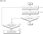
- FIG. 18 is a flowchart for illustrating an active retractor control method according to an embodiment of the present disclosure.
- a fluoroscopy image of a fractured bone fragments of the patient is taken until the distance to be retracted is checked at a separately provided imaging device (not shown in the drawings for convenience of description) (in case of "Yes” in the step S1902) (S1901).
- a retracting distance mode is input from the user in the controller 500 as a pre-retracting operation mode (S1903), and the retracting mode is set as the retracting distance mode according to the inputted retracting distance mode (S1904).
- the retracting distance mode is set as the pre-retraction operation mode in the step S1904 described above, retraction starts according to the retracting distance mode set in the actuator 300 (S1905), and the retracting force is measured after the retraction starts in the measuring device 200 (S1906). If the measured retracting force exceeds a limit retracting force (received from the user and stored in advance) (in case of "Yes" in the step S1907), the retraction is emergently stopped to complete the retraction, thereby preventing an excessive retracting force from being applied to the affected part of the patient (S1908).
- the controller 500 if the retraction is emergently stopped to complete the retraction, the controller 500 notifies the user of the emergency stop by a visual and audio device after the retraction stops, and the process may enter a normal mode again after inputting the confirmation of the user.
- the actuator 300 performs the retraction according to the initially set retracting distance mode under the control of the controller 500, and the measuring device 200 measures the retracting distance (S1909). After that, if the measured retracting distance does not reach the set retracting distance (in the case of "No” in the step S1910), the controller 500 adjusts the retracting distance (S1911).
- the controller 500 changes the retracting mode to the retracting force mode and performs the retraction (S1912), measures the retracting force (S1913), and stores the measured retracting force as a set value (S1914).
- the controller 500 adjusts the retracting force until the retracting force corresponds to the retracting request signal (S1916).
- the active retractor control method having the above steps may further include a step in which, as shown in FIG. 19 , after the retractor reaches a target retraction setting, a surgical operator directly moves a bone fragment tissue to complete fracture reposition or, if an additional retracting force is needed, the surgical operator capable of using the retractor moves the bone fragment tissue and performs fracture reposition.
- the bone fragment location of the patient is adjusted (S1810), and then the fluoroscopy image is photographed (S1820). If the fracture reposition is completed by adjusting the bone fragment in the step S1810 described above, the surgical operation is immediately terminated (in the case of "Yes" in the step S1830) without the retraction procedure as described above.
- the bone fragment location is adjusted again (S1810).
- step S1840 If the fracture reposition is not completed in the step S1840 described above and it is needed to adjust the retracting distance (in the case of "Yes” in the step S1840), the process comes to the step S1903 so that the retraction operation mode is set.
- the step of performing fracture reposition by moving the bone fragment tissue by the surgical operator is a step in which the surgical operator moves the bone fragment directly (by hand) to perform fracture reposition after the retraction is completed using the retractor.
- a pulling force is added to the fractured part to change the retracting force.
- the intention of the surgical operator is reflected on the compensation of the retractor for the retracting force, so the retractor is manipulated by direct teaching.
- a surgical operator/retractor collaboration step as shown in FIG. 20 may be further included.
- the retracting force is measured (S2020). Also, if the retracting force measured in the step S2020 is close to the set retracting force ("Yes” in the step S2030), the bone fragment location is adjusted again (S1810). If the retracting force measured in the step S2020 does not approach the set retracting force ("No” in the step S2030), the retracting force is adjusted (S2050), and then the retracting force is measured again until approaching the set retracting force.
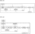
- FIG. 21 is a diagram for illustrating a control algorithm of the retracting distance mode.
- control is made based on a retracting location (a location command value), a retracting speed (a speed limit), and a retracting force (a torque limit) input by the manipulation of the user in a retractor Ul.
- FIG. 22 is a diagram for illustrating a control algorithm of the retracting force mode.
- the control algorithm of the retracting force mode after the stress between the fractured bone fragments is measured by the load cell, the measured retracting force becomes a torque control command and is controlled based on the retracting force limit (the torque limit) input by the manipulation of the user in the retractor UI.
- FIG. 23 is a diagram for illustrating a surgical operator/retractor collaborative control algorithm in the surgical operator/retractor collaborating step of FIG. 20 .
- a force obtained by adding the stress between the fractured bone fragments and the attractive force by the fracture reposition of the surgical operator is transferred to the load cell, and the measured retracting force becomes a location control command and is controlled based on the retracting speed (the speed limit) and the retracting force (the torque limit) input by the manipulation of the user in the retractor Ul.
Landscapes
- Health & Medical Sciences (AREA)
- Surgery (AREA)
- Life Sciences & Earth Sciences (AREA)
- Orthopedic Medicine & Surgery (AREA)
- Molecular Biology (AREA)
- Animal Behavior & Ethology (AREA)
- Engineering & Computer Science (AREA)
- Biomedical Technology (AREA)
- Heart & Thoracic Surgery (AREA)
- Medical Informatics (AREA)
- Nuclear Medicine, Radiotherapy & Molecular Imaging (AREA)
- Veterinary Medicine (AREA)
- General Health & Medical Sciences (AREA)
- Public Health (AREA)
- Pathology (AREA)
- Oral & Maxillofacial Surgery (AREA)
- Physics & Mathematics (AREA)
- General Physics & Mathematics (AREA)
- Orthopedics, Nursing, And Contraception (AREA)
- Surgical Instruments (AREA)
Abstract
Description
- This disclosure relates to an active retractor and a control method thereof, and more particularly, to an active retractor implemented to detect a stress state of a fractured area during fracture reposition and compensate for a required retracting force, and a control method thereof.
- The use of metal plates or metal tablets to fix fractured bones is commonplace. The metal plate is used by a surgeon to stabilize, correct or align the bone of a patient. The metal plate is typically fastened to bone fragments by a plurality of fastening units such as screws installed through holes formed in the plate.
- For most iliac fractures, the fractured bone fragments are contracted by the muscles, and bone fragments located far away must be properly retracted to align the bone fragments to their proper positions. After being retracting the bone fragments to the original positions, fracture reposition is performed by finely manipulating the bone fragments and fixed using a metal plate or a metal nail.
- Thus, there is a need for a tool that may be used to facilitate alignment and subsequent recombination of the fractured bone by applying a retracting force or a compression force thereto.
- For the retraction, a conventional retractor just retracts bone fragments by an attractive force or a mechanical configuration and then fix the bone fragments. However, in this method, the retraction is provided only at a fixed location against a stress change of the fractured area that is generated during a fracture reposition process, so there is a limit in providing a retracting force necessary for the intention of a surgical operator.
-
- (Patent Literature 0001) Korean Utility Model Registration No.
20-0216141 - (Patent Literature 0002) Korean Patent No.
10-1298059 - This disclosure is directed to providing an active retractor, which includes a sensor for a stress state of a fractured area, a controller and an actuator to provide a constant retracting force required for a fractured area in real time, and a control method thereof.
- The technical problem of the present disclosure is not limited to the technical problem mentioned above, and other technical problems not mentioned will be clearly understood by those skilled in the art from the following description.
- In one general aspect, there is provided an active retractor, comprising: a retracting shaft configured to fasten fractured bone fragments of a patient and retract the fractured bone fragments in a front and rear direction; a measuring device connected and installed to the retracting shaft to measure a retracting location or a retracting force of the retracting shaft; an actuator connected and installed to the retracting shaft to drive the retracting shaft in the front and rear direction; a driver configured to supply a power required for driving the actuator to the actuator according to a driving control signal; and a controller configured to generate a driving control signal, which is required for the driver to supply a power, by comparing a retracting request signal input from a user with a measured value transmitted from the measuring device and transmit the driving control signal to the driver.
- In an embodiment, the measuring device may include: a retracting force measuring sensor connected and installed to the retracting shaft to measure a tensile force or a compressive force of the retracting shaft and then generate tensile force information or compressive force information corresponding thereto to be transmitted to the controller; and a displacement measuring sensor connected and installed to the retracting shaft to measure a moved location of the retracting shaft and generate location information corresponding thereto to be transmitted to the controller.
- In an embodiment, the controller may include: a user interface unit configured to display number information and graphic information required for manipulation and receive the retracting request signal from the user; and a driving control unit configured to generate the driving control signal, which is required for the driver to supply a power, by comparing the retracting request signal received from the user interface unit with the measured value transmitted from the measuring device and transmit the driving control signal to the driver.
- In an embodiment, the user interface unit may receive a retracting force, a retracting speed, a retracting location, a retracting start/stop, an emergency stop, or postural adjustment of a retracting instrument.
- In an embodiment, the user interface unit may receive from the user a retracting distance mode in which a bone fragment is retracted to a retracting location set by the user and then the retracted bone fragment is fixed or a retracting force mode in which a bone fragment is retracted while constantly maintaining a stress of the bone fragment to a retracting force set by the user.
- In an embodiment, the driving control unit may generate retracting force information corresponding to the tensile force information or the compressive force information transmitted from the retracting force measuring sensor and transmit the retracting force information to the user interface unit.
- In an embodiment, the driving control unit may generate current location information or speed information of the retracting shaft corresponding to the location information transmitted from the displacement measuring sensor and transmit the current location information or speed information to the user interface unit.
- In an embodiment, the driving control signal may be a control signal about a retracting speed, a retracting location or a retracting force of the retracting shaft in a digital or analog form.
- In an embodiment, the active retractor may further comprise a foothold switch or a remote controller located within a work area of the user to receive a retracting request signal or an operation mode from the user and transmit the retracting request signal or the operation mode to the controller.
- In an embodiment, the active retractor may further comprise a location display device formed at one side of the actuator to display a driving location of the retracting shaft in real time.
- In an embodiment, the active retractor may further comprise a laser guide formed at one side of the actuator to guide a retracting direction and an aligning direction of a fractured area of a patient.
- In an embodiment, the active retractor may further comprise a retracting arm mounted and installed to the actuator to operate in the front and rear direction, one side of the retracting shaft being inserted in and fastened to the retracting arm so that the retracting shaft is driven in the front and rear direction by the retracting arm, the retracting arm releasing the fastening of the retracting shaft when a force equal to or greater than a preset force is applied thereto so that the retracting shaft is released.
- In another aspect of the present disclosure, there is also provided a active retractor control method, comprising: by a controller, receiving and setting a retracting request signal from a user; by the controller, allowing the user to select a retracting mode; by an actuator connected and installed to a retracting shaft, driving the retracting shaft in a front and rear direction under the control of the controller; by a measuring device connected and installed to a retracting shaft, measuring a retracting speed, a retracting location or a retracting force of the retracting shaft and generating a measured value corresponding thereto to be transmitted to the controller; by the controller, comparing the measured value transmitted from the measuring device with the retracting request signal received from the user; and by the controller, completing the retracting process and maintaining the retracting shaft in a fixed state when the measured value reaches the retracting request signal.
- In an embodiment, the active retractor control method may further comprise, before said receiving and setting a retracting request signal, photographing a fractured bone fragment of a patient as a fluoroscopy image and checking a distance by which the fractured bone fragment is to be retracted.
- In an embodiment, in said allowing the user to select a retracting mode, the user may be allowed to select a retracting distance mode in which a bone fragment is retracted to a set retracting location and then the retracted bone fragment is fixed or a retracting force mode in which a bone fragment is retracted while constantly maintaining a stress of the bone fragment to a set retracting force.
- In an embodiment, in said allowing the user to select a retracting mode, when a mode shifting request is received from the user while a bone fragment is retracted in one of the retracting distance mode and the retracting force mode, the retracting mode in progress may be temporarily stopped and the bone fragment may be retracted in the other retracting mode.
- In an embodiment, the active retractor control method may further comprise, by the controller, emergently stopping the driving of the retracting shaft, when the retracting force measured in said generating a measured value and transmitting to the controller exceeds a limit retracting force.
- In an embodiment, the active retractor control method may further comprise adjusting the retracting location or the retracting force of the retracting shaft, when the measured value fails to reach the retracting request signal, after said comparing.
- In an embodiment, said driving may include: by the controller, generating a driving control signal required for a driver to supply a power to the actuator and transmitting the driving control signal to the driver; by the driver, supplying a power required for driving the actuator to the actuator according to the driving control signal transmitted from the controller; and by the actuator, driving the retracting shaft in the front and rear direction according to the power supplied from the driver.
- According to an aspect of the present disclosure, the active retractor includes a sensor for a stress state of a fractured area, a controller and an actuator and thus may provide a constant retracting force required for a fractured area in real time, and a control method thereof.
-
-
FIG. 1 is a diagram showing a schematic configuration of an active retractor according to an embodiment of the present disclosure. -
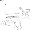
FIG. 2 shows the active retractor according to an embodiment of the present disclosure in use. -
FIG. 3 is a control block diagram for illustrating the controller depicted inFIG. 1 . -
FIG. 4 is a diagram for illustrating a retracting distance mode. -
FIG. 5 is a diagram showing a schematic configuration of an active retractor according to an embodiment of the present disclosure. -
FIG. 6 is a diagram showing another embodiment of the active retractor depicted inFIG. 1 . -
FIG. 7 is a diagram showing a schematic configuration of an active retractor according to an embodiment of the present disclosure. -
FIG. 8 is a diagram for illustrating a retracting arm depicted inFIG. 7 . -
FIG. 9 is a diagram for illustrating an operation method of the retracting arm depicted inFIG. 7 . -
FIG. 10 is a diagram for illustrating a relaxation damper depicted inFIG. 8 . -
FIG. 11 is a diagram for illustrating a load limiter depicted inFIG. 8 . -
FIG. 12 is a diagram for illustrating a housing depicted inFIG. 11 . -
FIG. 13 is a diagram for illustrating an operation method of the load limiter depicted inFIG. 8 . -
FIG. 14 is a diagram for illustrating a load adjusting unit depicted inFIG. 11 . -
FIGS. 15 and16 are flowcharts for illustrating an active retractor control method according to an embodiment of the present disclosure. -
FIG. 17 is a flowchart for illustrating a driving step depicted inFIG. 15 . -
FIG. 18 is a flowchart for illustrating an active retractor control method according to an embodiment of the present disclosure. -
FIG. 19 is a flowchart for illustrating a surgical operation step in which bone fragment tissues are moved by a surgical operator to perform fracture reposition. -
FIG. 20 is a flowchart for illustrating a case where the control mode ofFIG. 19 is a retracting force mode. -
FIGS. 21 to 23 are diagrams for illustrating an algorithm according to each control mode of the retractor. - The following detailed description of the present disclosure refers to the accompanying drawings that show, by way of illustration, specific embodiments in which the present disclosure may be practiced. These embodiments are fully described in detail to enable those skilled in the art to implement the present disclosure. It should be understood that the various embodiments of the present disclosure are different but need not be exclusive to each other. For example, certain shapes, structures and characteristics described herein may be implemented in other embodiments without departing from the scope of the present disclosure in connection with one embodiment. In addition, it is to be understood that the location or arrangement of individual components disclosed in each embodiment may be changed without departing from the scope of the present disclosure. Accordingly, the following detailed description is not to be taken in a limiting sense, and the scope of the present disclosure, if properly described, is defined only by the appended claims along with the full range of equivalents to which such claims are entitled. Like reference numerals in the drawings designate the same or similar functions throughout the several drawings.
- Hereinafter, preferred embodiments of the present disclosure will be described in detail with reference to the drawings.
-
FIG. 1 is a diagram showing a schematic configuration of an active retractor according to an embodiment of the present disclosure. - Specifically, an
active retractor 10 according to an embodiment of the present disclosure includes a retractingshaft 100, a measuringdevice 200, anactuator 300, adriver 400, and acontroller 500. - The retracting
shaft 100 is connected and installed to theactuator 300 and is fastened to a fractured bone fragment of a patient and retracts the fractured bone fragment in a front and rear direction. - In an embodiment, the retracting
shaft 100 may include a gripping means provided at one side terminal thereof to grip a bone fragment of the patient. - The measuring
device 200 is connected and installed to the retractingshaft 100 to measure a retracting location or a retracting force of the retractingshaft 100. - In an embodiment, the measuring
device 200 includes a retractingforce measuring sensor 210 and adisplacement measuring sensor 220. - The retracting
force measuring sensor 210 is directly connected and installed to the retractingshaft 100 and measures a tensile force or a compressive force of the retractingshaft 100 and generates corresponding tensile force information or compressive force information corresponding thereto. Also, the retractingforce measuring sensor 210 transmits the corresponding tensile force information or the corresponding compressive force information to thecontroller 500. - In an embodiment, as a sensor that may be applied as the retracting
force measuring sensor 210, a load cell or a pressure sensor may be used directly. Also, the retractingforce measuring sensor 210 may use a principle of measuring displacement generated by an acting force. - The
displacement measuring sensor 220 is directly connected and installed to the retractingshaft 100, measures a moved location of the retractingshaft 100, generates location information corresponding thereto, and transmits the generated location information to thecontroller 500. - In an embodiment, as a sensor that may be applied as the
displacement measuring sensor 220, an optical/magnetic absolute encoder, an optical/magnetic incremental encoder, or a photo interrupt or a hall switch may be applied to a required position. - The
actuator 300 is connected and installed to the retractingshaft 100, receives a power from thedriver 400, and drives the retractingshaft 100 in the front and rear direction in response to the supplied power. - In an embodiment, the
actuator 300 corresponds to a driving unit that generates a linear movement and a retracting force for moving a bone fragment to a location necessary for retracting, and may include a reducer capable of adjusting speed and torque according to an electric control of thedriver 400 and a ball screw for converting rotational movement of the reducer into linear movement. - The
driver 400 receives a driving control signal from thecontroller 500 and supplies a power required for driving theactuator 300 to theactuator 300 according to the received driving control signal. - In an embodiment, the
driver 400 supplies a power required for driving theactuator 300 to theactuator 300 according to the control signal of thecontroller 500, and thedriver 400 may be a three-phase inverter including a speed and torque controller or a power switch in the form of a pulse width modulation (PWM) control. - The
controller 500 compares the retracting request signal input from the user with a measured value transmitted from the measuringdevice 200, generates a driving control signal, which is required for thedriver 400 to supply a power, corresponding to the compared value, and transmits the corresponding driving control signal to thedriver 400. - In an embodiment, the
controller 500 may output the control signal required for thedriver 400 by comparing the retracting request signal set by the user to follow the retracting force, the retracting location and the retracting speed with the measured values of the retractingforce measuring sensor 210 and thedisplacement measuring sensor 220. - In an embodiment, the
controller 500 may calculate information about a stress of the fractured area measured by the retractingforce measuring sensor 210 and calculate a speed by differentiating the measured position with respect to the current position and time of the retractingshaft 100 measured by thedisplacement measuring sensor 220. Also, thecontroller 500 may compare the information calculated by each sensor with user setting formation and transmit a driving control signal to thedriver 400 to maintain the necessary retracting force and the necessary retracting location. Here, the driving control signal transmitted to thedriver 400 is a control signal about speed, location and retracting force and may be in a digital or analog form. - The
active retractor 10 configured as above may further include adisplay device 310 and a laser guide 320 (seeFIG. 6 ). - The
display device 310 is formed at one side of theactuator 300, and displays a driving location of the retractingshaft 100 in real time or a maximum contraction/relaxation state of a pulling rod of the retractingshaft 100. In this case, thedisplay device 310 displays the maximum extension state of the retractingshaft 100 as "Full forward", displays the maximum contraction state as "Full back", and divides the state into a plurality of stages so that the user may visually recognize the retracting state of the retractingshaft 100 in an easy way. - The
laser guide 320 is formed at one side of theactuator 300 and may irradiate a guide laser to guide a retracting direction and an alignment direction of the fractured area of the patient. - The
active retractor 10 configured as above includes ameasuring device 200 capable of detecting a stress state of the fractured area during fracture reposition, acontroller 500 and anactuator 300, thereby providing a constant retracting force necessary for the fractured area in real time. -
FIG. 3 is a control block diagram for illustrating the controller depicted inFIG. 1 . - Referring to 3, the
controller 500 includes auser interface unit 510 and a drivingcontrol unit 520. - The
user interface unit 510 displays number information and graphic information necessary for manipulation, receives a retracting request signal from the user, and transmits the received retracting request signal to the drivingcontrol unit 520. - Referring to
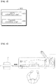
FIG. 6 , theuser interface unit 510 may implement a user interface in consideration of the retractor characteristics and fracture reposition procedure. First, 1) in a wizard mode, theuser interface unit 510 implements an environment that enables the user to perform safe manipulation without knowing the manual and provides a step-by-step method in which the setting and check items for each step are displayed and confirmed by the user, and 2) in askill mode 512, theuser interface unit 510 provides only a basic panel that displays various setting values and a state of the driver to support a rapid use environment for experienced users. - In an embodiment, the
user interface unit 510 is a device for displaying numerical information and graphic information necessary for retractor operation, and may utilize a GUI program based on a mechanical electrical contact or a touch screen. A main user display (output) function of theuser interface unit 510 may display a retracting force, a retracting speed and a retracting location currently measured as well as various alarms such as a retracting upper limit, a retracting lower limit and a retracting-executing mark. Also, a main user input function of theuser interface unit 510 may support a manipulation panel for retracting force setting input, retracting speed setting input, retracting location setting input, retracting start/stop, emergency stop, and retracting instrument postural adjustment. - In an embodiment, the
user interface unit 510 may have a simple display form in which necessary setting inputs and displays are listed on the screen for user convenience and safe use, or a manual (wizard) display form in which need-to-know items or medical information important for the retractor operation of the user are displayed sequentially suitable for the surgical operation procedure so as to be checked by the user. - In an embodiment, the
user interface unit 510 is a hardware interface for user convenience. In order to improve visibility and operation inconvenience caused by a long distance from a manipulating panel (the user interface) of the retractor or a deviation from a work area of the user, afoothold switch 700 and aremote controller 600, explained later with reference toFIG. 5 , may be provided in the work area of the user. - The driving
control unit 520 receives the retracting request signal from theuser interface unit 510, receives the measured value from the measuringdevice 200, compares the received retracting request signal with the measured value, and generates a driving control signal required for power supply to thedriver 400 corresponding value to the compared value, and transmits the corresponding generated driving control signal to thedriver 400. - In an embodiment, the
user interface unit 510 may receive a retracting force, a retracting speed, a retracting location, a retracting start/stop, an emergency stop, or postural adjustment of the retracting instrument. - In an embodiment, the
user interface unit 510 may receive from the user a retracting distance mode in which a bone fragment is retracted to a retracting location set by the user and then the retracted bone fragment is fixed, or a retracting force mode in which a bone fragment is retracted while maintaining the stress of the bone fragment to a retracting force set by the user. - At this time, the retracting distance mode may be utilized when a bone fragment is always fixed at a constant position after fracture reposition is completed since the bone fragment is moved and then the retraction is fixed. In the retracting force mode, retraction is performed while maintaining the stress of the bone fragment as much as the retracting force set by the user, so the retracting force mode may be utilized when stable relaxation minimizing muscle tissue damage in an over-rap state caused by muscle contraction on the fractured area is required before fracture reposition or when the fracture reposition is required. In particular, when the fracture reposition is performed, the retractor compensates for the stress of the fractured area on the influence of the attraction caused by the invention of a surgical operator, thereby reducing the burden on the surgical operator and enabling a stable fracture reposition procedure.
- For example, referring to
FIG. 4 , the foot of the patient is retracted by a preset distance (for example, 5 cm to 20 cm) and fixed according to the present disclosure, which allows the surgical operator to avoid unnecessary forces and to make precise retraction, thereby ensuring the accuracy and stability of the surgical operation. - In an embodiment, the driving
control unit 520 may generate retracting force information corresponding to the tensile force information or the compressive force information transmitted from the retractingforce measuring sensor 210, and transmit the retracting force information to theuser interface unit 510. - In an embodiment, the driving
control unit 520 may generate current location information or speed information of the retractingshaft 100 corresponding to the location information transmitted from thedisplacement measuring sensor 220 and transmit the generated information to theuser interface unit 510. - In an embodiment, the driving control signal is a control signal for retracting speed, retracting location or retracting force of the retracting
shaft 100 and may be a digital or analog signal. - In an embodiment, the driving
control unit 520 may calculate the information on the stress of the fractured area measured by the retractingforce measuring sensor 210 and transmit the information to theuser interface unit 510, and may calculate the speed by differentiating the location measured with respect to the current location and time of the retractingshaft 100 measured by thedisplacement measuring sensor 220 and transmit the calculated location and speed information to theuser interface unit 510. - In an embodiment, the driving
control unit 520 may transmit the measured values measured by the retractingforce measuring sensor 210 and thedisplacement measuring sensor 220 to theuser interface unit 510 to be displayed on theuser interface unit 510. -
FIG. 5 is a diagram showing a schematic configuration of an active retractor according to an embodiment of the present disclosure. - Specifically, the
active retractor 20 according to an embodiment of the present disclosure includes a retractingshaft 100, a measuringdevice 200, anactuator 300, adriver 400, acontroller 500, afoothold switch 700, and aremote controller 600. Here, the retractingshaft 100, the measuringdevice 200, theactuator 300, thedriver 400 and thecontroller 500 are the same as the components of shown inFIG. 1 and thus will not described in detail here. - The
remote controller 600 is located within the work area of the user, and receives the retracting request signal (for example, a request signal for changing the location of the retractingshaft 100 or increasing or decreasing the retracting force of the retracting shaft 100) or an operation mode from the user and transmits the corresponding retracting request signal to thecontroller 500 through wired or wireless communication. - The
foothold switch 700 is located within the work area of the user. If the user is not able to use both hands for reasons such as surgery, thefoothold switch 700 receives a retracting request signal (for example, a request signal for changing the location of the retractingshaft 100 or increasing or decreasing the retracting force of the retracting shaft 100) or an operation mode and transmits the same to thecontroller 500. -
FIG. 7 is a diagram showing a schematic configuration of an active retractor according to an embodiment of the present disclosure. - Specifically, the
active retractor 30 according to an embodiment of the present disclosure includes a retractingshaft 100, a measuringdevice 200, anactuator 300, adriver 400, acontroller 500, and a retractingarm 800. Here, the retractingshaft 100, the measuringdevice 200, theactuator 300, thedriver 400 and thecontroller 500 are the same as the components ofFIG. 1 and thus will not be described in detail here. - The retracting
arm 800 is mounted and installed to theactuator 300 and is driven in the front and rear direction corresponding to the driving of theactuator 300. Also, one side of the retractingshaft 100 is inserted into the retractingarm 800 and fastened thereto so that the retractingshaft 100 is driven in the front and rear direction, and the fastening is released if a force greater than a preset force is applied thereto, to relax the retractingshaft 100. - The
active retractor 30 configured as above implements a double safety device as a stabilizer of a mechanical configuration independent from an electrical device, and it is possible to prevent a safety accident that an excessive force is transferred to an affected part during the retracting process. -
FIG. 8 is a diagram for illustrating a retracting arm depicted inFIG. 7 . - Referring to
FIG. 8 , the retractingarm 800 includes arelaxation damper 810 and aload limiter 820. - The
relaxation damper 810 is mounted and installed to theactuator 300, and one side of the retractingshaft 100 is inserted into an insert groove formed therein. Also, when the retractingshaft 100 is released and relaxed from the insert groove, therelaxation damper 810 absorbs a part of the transferred force. - The
load limiter 820 is mounted and installed to an open one side of therelaxation damper 810 and fastens the retractingshaft 100. When a force equal to or greater than a preset force is supplied thereto from theactuator 300, theload limiter 820 releases the fastening. - In a normal state in which the
retracting arm 800 configured as above retracts the affected part with a suitable force as shown inFIG. 9(A) , theactuator 300 and the retractingarm 800 serving as a safety device are moved together to transmit the retracting force of theactuator 300. However, in an abnormal state in which an excessive force is applied to damage the affected part, as shown inFIG. 9(B) , theload limiter 820 fastened to the retractingshaft 100 releases the fastening to separate the retractingshaft 100 from therelaxation damper 810, and therelaxation damper 810 may slowly perform a relaxation operation with a maximum stroke (a maximum stroke of the relaxation damper 810) by itself. -
FIG. 10 is a diagram for illustrating a relaxation damper depicted inFIG. 8 . - Referring to
FIG. 10 , therelaxation damper 810 includes apiston body 811, apiston unit 812, and a relaxationelastic unit 813. - The
piston body 811 has an insert groove formed therein so that one side of the retractingshaft 100 is inserted therein, and thepiston body 811 is connected and installed to theactuator 300. - The
piston unit 812 is mounted and installed to one end of the retractingshaft 100 and slides in the front and rear direction in the insert groove of thepiston body 811. - The relaxation
elastic unit 813 is inserted between the insert groove of thepiston body 811 and thepiston unit 812 to press thepiston unit 812 in one direction. - In an embodiment, the relaxation
elastic unit 813 may be implemented as a spring, a solid or a fluid. - In the
relaxation damper 810 configured as above, if the retractingshaft 100 comes into a freely movable state without restraint as shown inFIG. 13(B) as theload limiter 820 is loosened, thepiston unit 812 is prevented from suddenly sliding in the front and rear direction in the insert groove of thepiston body 811 due to the elastic force of the relaxationelastic unit 813, so therelaxation damper 810 may slowly perform a relaxation operation with a maximum stroke (a maximum stroke of the relaxation damper 810) by itself. -
FIG. 11 is a diagram for illustrating a load limiter depicted inFIG. 8 . - Referring to
FIG. 11 , theload limiter 820 includes ahousing 821, a plurality offastening units 822, apressing unit 823, anelastic unit 824, a supportingunit 825, and aload adjusting unit 826. - The
housing 821 is mounted and installed to one side of therelaxation damper 810, so that the plurality offastening unit 822, thepressing unit 823, theelastic unit 824, the supportingunit 825 and theload adjusting unit 826 are accommodated in a space formed therein. - In an embodiment, the
housing 821 may form a funnel-shapedinclined surface 827 at an inner portion thereof (seeFIG. 12 ). - In an embodiment, the
housing 821 may have afastening thread 828 formed at an inlet portion thereof to fasten the insert thread 8263 (seeFIG. 12 ). - The
fastening unit 822 is fastened to thefastening groove 110 formed at an outer surface of the retractingshaft 100. - In an embodiment, the
fastening unit 822 may be formed in a spherical shape or a wedge shape. - In an embodiment, the
fastening unit 822 may move into thehousing 821 along theinclined surface 827 to fasten thefastening groove 110 as the distance from anotherfastening unit 822 decreases. - The
pressing unit 823 is connected and installed to the other side of thefastening unit 822 to press thefastening unit 822 into thehousing 821. - The
elastic unit 824 is connected and installed to the other side of thepressing unit 823 to press thepressing unit 823 into thehousing 821 by an elastic force. - The supporting
unit 825 is inserted into the other side of theelastic unit 824 to support theelastic unit 824. - The
load adjusting unit 826 is mounted and installed to one open side of thehousing 821 to adjust the insertion location of the supportingunit 825. - The
load limiter 820 configured as above may release thefastening unit 822 when the force supplied from theactuator 300 is greater than the fastening force of thefastening unit 822 that fastens thefastening groove 110. - The
load limiter 820 configured as above adjusts the fastening force of thefastening unit 822 placed in thefastening groove 110 of the retractingshaft 100 by the tension of theelastic unit 824, to release thefastening unit 822 when the force applied to the retractingshaft 100 is greater than the tightening force, thereby preventing an excessive force from being transferred to the retractingshaft 100. - In the
load limiter 820 configured as above, in a normal state in which a force smaller than the force set by the retractingshaft 100 is transmitted, the fastening of theload limiter 820 is not released from the retractingshaft 100 as shown inFIG. 13(A) and thus may move together with therelaxation damper 810 in the left and right direction. However, in an abnormal state in which a force greater than the force set by the retractingshaft 100 is transmitted, thefastening unit 822 moves along thefastening groove 110 of the retractingshaft 100 and is pushed by the compressive force of theelastic unit 824 to deviate from thefastening groove 110 of the retractingshaft 100, so thefastening unit 822 is released from the retractingshaft 100 as shown inFIG. 13(B) to deviate from the binding force of thefastening unit 822. Thus, the retracting force transmitted through thefastening unit 822 is interrupted and the retractingshaft 100 comes into a freely movable state without restraint. - At this time, if the retracting
shaft 100 is in the freely movable state, since a sudden movement may occur due to the external environment, therelaxation damper 810 is provided thereto to prevent the sudden movement. -
FIG. 14 is a diagram for illustrating a load adjusting unit depicted inFIG. 11 . - Referring to
FIG 14 , theload adjusting unit 826 includes a handle means 8261, an adjustment means 8262 and a cover means 8264. - The handle means 8261 has an adjustment means 8262 formed on one side and allows the user to grip and rotate the handle means 8261 by hand.
- The adjustment means 8262 is formed at one side of the handle means 8261 to adjust the insertion location of the supporting
unit 825 while being inserted into or separated from thehousing 821 in response to the rotation direction of the handle means 8261. - In an embodiment, the adjustment means 8262 may have an
insert thread 8263 formed at an outer side so as to be fastened to thehousing 821. - The cover means 8264 extends from the handle means 8261 toward the
housing 821 to cover the open one side of thehousing 821. - In an embodiment, the cover means 8264 may have an uneven portion formed at an outer surface thereof to form a frictional force when being gripped by hand of the user.
-
FIG. 15 is a flowchart for illustrating an active retractor control method according to an embodiment of the present disclosure. - Referring to
FIG. 15 , in an active retractor control method, firstly, thecontroller 500 receives and sets a retracting request signal from a user (S1410). - If the retracting request signal is input in the step S1410, the
controller 500 allows the user to select a retracting mode (S1420). - In an embodiment, in the step (S1420) of allowing the user to select a retracting mode, as shown in
FIG. 16 , the retracting distance mode in which a bone fragment location is moved by the set retracting location and then the retracted bone fragment location is fixed (FIG. 16A , in the case of the "retracting distance mode" in the step S1420) or the retracting force mode in which a bone fragment is retracted while constantly maintaining the stress by the set retracting force (FIG. 16B , in the case of the "retracting force mode" in the step S1420) may be selected by the user. - In an embodiment, the step S1420 of allowing the user to select a retracting mode, while the retraction is being performed in any one of the retracting distance mode and the retracting force mode, if a mode shifting request is received from the user, the retracting mode in progress is temporarily stopped, and then the retraction is performed in the other mode. If the mode is changed from the retracting distance mode to the retracting force mode, the retracting force value measured in the retracting distance mode is set as an initial setting value of the retracting force. However, the initial setting value may be increased or decreased according to an input of the user.
- If the retracting mode is selected in the step S1420 described above, the
actuator 300 connected and installed to the retractingshaft 100 drives the retractingshaft 100 in the front and rear direction under the control of the controller 500 (S1430). - If the retracting
shaft 100 is driven in the step S1430 described above, the measuringdevice 200 connected and installed to the retractingshaft 100 measures a tensile force, a compressive force or a moved location of the retractingshaft 100 and then generates a measured value corresponding thereto and transmits the measured value to the controller 500 (S1440). - In an embodiment, in the step S1440 described above, as shown in
FIG. 16 , thedisplacement measuring sensor 220 measures a moved position of the retracting shaft 100 (FIG. 16A , S1440) or the retractingforce measuring sensor 210 measures a retracting force of the retracting shaft 100 (FIG. 16B , S1440). - If the measured value is transmitted in the step S1440 described above, the
controller 500 compares the measured value transmitted from the measuringdevice 200 with the retracting request signal input from the user (S1450). - In an embodiment, in the step S1450 described above, if the retracting location of the
retractor 100 does not reach the retracting request signal in the "retracting distance mode" as shown inFIG. 16A (in case of "No" in the step S1450), the step S1470 of readjusting the retracting location is executed as described below. However, if the retracting location of theretractor 100 reaches the retracting request signal (in case of "Yes" in the step S1450), the retraction is completed and the process proceeds to the step S1460 of fixing theretractor 100. In addition, if the retracting force of theretractor 100 does not reach the retracting request signal in the "retracting force mode" as shown inFIG. 16B (in the case of "No" of the step S1450), the step S1470 is executed. However, if the retracting force of theretractor 100 reaches the retracting request signal (in case of "Yes" of the step S1450), the retraction is completed and the process may proceed to the step S1460 of fixing theretractor 100. - When the retracting request signal is compared in the step S1450 described above, if the measured value reaches the retracting request signal, the
controller 500 completes the retracting and maintains the retractingshaft 100 in a fixed state (S1460). - The active retractor control method having the steps as described above may further include, after the step S1450 of comparing, a step of adjusting the retracting force (the tensile force or the compressive force) or the moved location of the retracting
shaft 100 if the measured value does not reach the retracting request signal (S1470 ofFIG. 16 ). -
FIG. 17 is a flowchart for illustrating a driving step depicted inFIG. 15 . - Referring to
FIG. 17 , in the step S1430 of driving, firstly, thecontroller 500 generates a driving control signal required for thedriver 400 to supply a power to theactuator 300, and transmits the driving control signal to the driver 400 (S1431). - If the driving control signal is transmitted in the step S1430 described above, the
driver 400 supplies a power required for driving theactuator 300 to theactuator 300 according to the driving control signal transmitted from the controller 500 (S1432). - If power is supplied in the step S1432 described above, the
actuator 300 drives the retractingshaft 100 in the front and rear direction according to the power supplied from the driver 400 (S1433). -
FIG. 18 is a flowchart for illustrating an active retractor control method according to an embodiment of the present disclosure. - Referring to
FIG. 18 , in the active retractor control method, firstly, a fluoroscopy image of a fractured bone fragments of the patient is taken until the distance to be retracted is checked at a separately provided imaging device (not shown in the drawings for convenience of description) (in case of "Yes" in the step S1902) (S1901). - If the distance to be retracted is checked in the step S1902 described above, a retracting distance mode is input from the user in the
controller 500 as a pre-retracting operation mode (S1903), and the retracting mode is set as the retracting distance mode according to the inputted retracting distance mode (S1904). - The retracting distance mode is set as the pre-retraction operation mode in the step S1904 described above, retraction starts according to the retracting distance mode set in the actuator 300 (S1905), and the retracting force is measured after the retraction starts in the measuring device 200 (S1906). If the measured retracting force exceeds a limit retracting force (received from the user and stored in advance) (in case of "Yes" in the step S1907), the retraction is emergently stopped to complete the retraction, thereby preventing an excessive retracting force from being applied to the affected part of the patient (S1908).
- In an embodiment, if the retraction is emergently stopped to complete the retraction, the
controller 500 notifies the user of the emergency stop by a visual and audio device after the retraction stops, and the process may enter a normal mode again after inputting the confirmation of the user. - If the retracting force does not exceed the limit retracting force in the step S1907 described above (in the case of "No" in the step S1907), the
actuator 300 performs the retraction according to the initially set retracting distance mode under the control of thecontroller 500, and the measuringdevice 200 measures the retracting distance (S1909). After that, if the measured retracting distance does not reach the set retracting distance (in the case of "No" in the step S1910), thecontroller 500 adjusts the retracting distance (S1911). - If the retracting distance measured in the step S1910 described above reaches the set retracting distance (in the case of "Yes" in the step S1910), the
controller 500 changes the retracting mode to the retracting force mode and performs the retraction (S1912), measures the retracting force (S1913), and stores the measured retracting force as a set value (S1914). - If the retracting force stored in the above step S1914 does not approach the retracting request signal input from the user (in the case of "No" in the step S1915), the
controller 500 adjusts the retracting force until the retracting force corresponds to the retracting request signal (S1916). - If the retracting force measured in the step S1913 described above corresponds to the retracting request signal (in case of "Yes" of the step S1915), the retraction is completed and fixed (S1917).
- The active retractor control method having the above steps may further include a step in which, as shown in
FIG. 19 , after the retractor reaches a target retraction setting, a surgical operator directly moves a bone fragment tissue to complete fracture reposition or, if an additional retracting force is needed, the surgical operator capable of using the retractor moves the bone fragment tissue and performs fracture reposition. - In the step of performing fracture reposition by moving the bone fragment tissue by the surgical operator, firstly, the bone fragment location of the patient is adjusted (S1810), and then the fluoroscopy image is photographed (S1820). If the fracture reposition is completed by adjusting the bone fragment in the step S1810 described above, the surgical operation is immediately terminated (in the case of "Yes" in the step S1830) without the retraction procedure as described above.
- If the fracture reposition is not completed by adjusting the bone fragment in the step S1830 described above (in the case of "No" in the step S1830), or if the retracting distance adjustment is not necessary through the fluoroscopy image (in the step of "No" in the step S1840), the bone fragment location is adjusted again (S1810).
- If the fracture reposition is not completed in the step S1840 described above and it is needed to adjust the retracting distance (in the case of "Yes" in the step S1840), the process comes to the step S1903 so that the retraction operation mode is set.
- The step of performing fracture reposition by moving the bone fragment tissue by the surgical operator is a step in which the surgical operator moves the bone fragment directly (by hand) to perform fracture reposition after the retraction is completed using the retractor. At this time, since the bone fragment is moved directly by hand, a pulling force is added to the fractured part to change the retracting force. If the control mode of the retractor is the retracting force mode, the retractor attempts to compensate for the retracting force generated by the pulling and pushing force of the surgical operator (during a bone fragment repositioning process (= fracture reposition)). However, the intention of the surgical operator is reflected on the compensation of the retractor for the retracting force, so the retractor is manipulated by direct teaching.
- In the step of performing the fracture reposition by moving the bone fragment tissue by the surgical operator as described above, if the control mode of the retractor is maintained in the retracting force mode, a surgical operator/retractor collaboration step as shown in
FIG. 20 may be further included. - When the bone fragment location is adjusted in the step S1810 described above, if the operation mode is the retracting force mode ("Yes" in the step S2010), the retracting force is measured (S2020). Also, if the retracting force measured in the step S2020 is close to the set retracting force ("Yes" in the step S2030), the bone fragment location is adjusted again (S1810). If the retracting force measured in the step S2020 does not approach the set retracting force ("No" in the step S2030), the retracting force is adjusted (S2050), and then the retracting force is measured again until approaching the set retracting force.
- Finally, a control algorithm used in each retracting mode according to each embodiment of the present disclosure will be described as follows.
- First,
FIG. 21 is a diagram for illustrating a control algorithm of the retracting distance mode. In the control algorithm of the retraction distance mode, control is made based on a retracting location (a location command value), a retracting speed (a speed limit), and a retracting force (a torque limit) input by the manipulation of the user in a retractor Ul. - Next,
FIG. 22 is a diagram for illustrating a control algorithm of the retracting force mode. In the control algorithm of the retracting force mode, after the stress between the fractured bone fragments is measured by the load cell, the measured retracting force becomes a torque control command and is controlled based on the retracting force limit (the torque limit) input by the manipulation of the user in the retractor UI. -
FIG. 23 is a diagram for illustrating a surgical operator/retractor collaborative control algorithm in the surgical operator/retractor collaborating step ofFIG. 20 . Here, in the surgical operator/retractor collaborative control algorithm, a force obtained by adding the stress between the fractured bone fragments and the attractive force by the fracture reposition of the surgical operator is transferred to the load cell, and the measured retracting force becomes a location control command and is controlled based on the retracting speed (the speed limit) and the retracting force (the torque limit) input by the manipulation of the user in the retractor Ul. - Although the present disclosure has been described above with reference to the embodiments, it can be understood that the present disclosure can be variously modified and changed by those skilled in the art without departing from the scope of the present disclosure defined in the appended claims.
[Reference Symbols] 100: retracting shaft 110: fastening groove 200: measuring device 210: retracting force measuring sensor 220: displacement measuring sensor 300: actuator 310: location display device 320: laser guide 400: driver 500: controller 510: user interface unit 511: Wizard Mode 512: Skill Mode 520: driving control unit 700: foothold switch 600: remote controller 800: retracting arm 810: relaxation damper 811: piston body 812: piston unit 813: relaxation elastic unit 820: load limiter 821: housing 822: fastening unit 823: pressing unit 824: elastic unit 825: supporting unit 826: load adjusting unit 8261: handle means 8262: adjustment means 8263: insert thread 8264: cover means 827: inclined surface 828: fastening thread
Claims (18)
- An active retractor, comprising:a retracting shaft configured to fasten fractured bone fragments of a patient and retract the fractured bone fragments in a front and rear direction;a measuring device connected and installed to the retracting shaft to measure a retracting location or a retracting force of the retracting shaft;an actuator connected and installed to the retracting shaft to drive the retracting shaft in the front and rear direction;a driver configured to supply a power required for driving the actuator to the actuator according to a driving control signal; anda controller configured to generate a driving control signal, which is required for the driver to supply a power, by comparing a retracting request signal input from a user with a measured value transmitted from the measuring device and transmit the driving control signal to the driver.
- The active retractor according to claim 1,
wherein the measuring device includes:a retracting force measuring sensor connected and installed to the retracting shaft to measure a tensile force or a compressive force of the retracting shaft and then generate tensile force information or compressive force information corresponding thereto to be transmitted to the controller; anda displacement measuring sensor connected and installed to the retracting shaft to measure a moved location of the retracting shaft and generate location information corresponding thereto to be transmitted to the controller. - The active retractor according to claim 2,
wherein the controller includes:a user interface unit configured to display number information and graphic information required for manipulation and receive the retracting request signal from the user; anda driving control unit configured to generate the driving control signal, which is required for the driver to supply a power, by comparing the retracting request signal received from the user interface unit with the measured value transmitted from the measuring device and transmit the driving control signal to the driver. - The active retractor according to claim 3,
wherein the user interface unit receives a retracting force, a retracting speed, a retracting location, a retracting start/stop, an emergency stop, or postural adjustment of a retracting instrument. - The active retractor according to claim 3,
wherein the user interface unit receives from the user a retracting distance mode in which a bone fragment is retracted to a retracting location set by the user and then the retracted bone fragment is fixed or a retracting force mode in which a bone fragment is retracted while constantly maintaining a stress of the bone fragment to a retracting force set by the user. - The active retractor according to claim 3,
wherein the driving control unit generates retracting force information corresponding to the tensile force information or the compressive force information transmitted from the retracting force measuring sensor and transmits the retracting force information to the user interface unit. - The active retractor according to claim 3,
wherein the driving control unit generates current location information or speed information of the retracting shaft corresponding to the location information transmitted from the displacement measuring sensor and transmits the current location information or speed information to the user interface unit. - The active retractor according to claim 3,
wherein the driving control signal is a control signal about a retracting speed, a retracting location or a retracting force of the retracting shaft in a digital or analog form. - The active retractor according to claim 1, further comprising:
a foothold switch or a remote controller located within a work area of the user to receive a retracting request signal or an operation mode from the user and transmit the retracting request signal or the operation mode to the controller. - The active retractor according to claim 1, further comprising:
a location display device formed at one side of the actuator to display a driving location of the retracting shaft in real time. - The active retractor according to claim 10, further comprising:
a laser guide formed at one side of the actuator to guide a retracting direction and an aligning direction of a fractured area of a patient. - The active retractor according to claim 1, further comprising:
a retracting arm mounted and installed to the actuator to operate in the front and rear direction, one side of the retracting shaft being inserted in and fastened to the retracting arm so that the retracting shaft is driven in the front and rear direction by the retracting arm, the retracting arm releasing the fastening of the retracting shaft when a force equal to or greater than a preset force is applied thereto so that the retracting shaft is released. - An active retractor control method, comprising:by a controller, receiving and setting a retracting request signal from a user;by the controller, allowing the user to select a retracting mode;by an actuator connected and installed to a retracting shaft, driving the retracting shaft in a front and rear direction under the control of the controller;by a measuring device connected and installed to a retracting shaft, measuring a retracting speed, a retracting location or a retracting force of the retracting shaft and generating a measured value corresponding thereto to be transmitted to the controller;by the controller, comparing the measured value transmitted from the measuring device with the retracting request signal received from the user; andby the controller, completing the retracting process and maintaining the retracting shaft in a fixed state when the measured value reaches the retracting request signal.
- The active retractor control method according to claim 13, further comprising:
before said receiving and setting a retracting request signal, photographing a fractured bone fragment of a patient as a fluoroscopy image and checking a distance by which the fractured bone fragment is to be retracted. - The active retractor control method according to claim 13,
wherein in said allowing the user to select a retracting mode, the user is allowed to select a retracting distance mode in which a bone fragment is retracted to a set retracting location and then the retracted bone fragment is fixed or a retracting force mode in which a bone fragment is retracted while constantly maintaining a stress of the bone fragment to a set retracting force. - The active retractor control method according to claim 15,
wherein in said allowing the user to select a retracting mode, when a mode shifting request is received from the user while a bone fragment is retracted in one of the retracting distance mode and the retracting force mode, the retracting mode in progress is temporarily stopped and the bone fragment is retracted in the other retracting mode. - The active retractor control method according to claim 13, further comprising:
by the controller, emergently stopping the driving of the retracting shaft, when the retracting force measured in said generating a measured value and transmitting to the controller exceeds a limit retracting force. - The active retractor control method according to claim 13, further comprising:
adjusting the retracting location or the retracting force of the retracting shaft, when the measured value fails to reach the retracting request signal, after said comparing.
Applications Claiming Priority (2)
| Application Number | Priority Date | Filing Date | Title |
|---|---|---|---|
| KR1020170138302A KR102168431B1 (en) | 2017-10-24 | 2017-10-24 | Active Retractor and Control Method thereof |
| PCT/KR2018/012491 WO2019083237A1 (en) | 2017-10-24 | 2018-10-22 | Active traction device and control method therefor |
Publications (3)
| Publication Number | Publication Date |
|---|---|
| EP3701891A1 true EP3701891A1 (en) | 2020-09-02 |
| EP3701891A4 EP3701891A4 (en) | 2021-08-11 |
| EP3701891B1 EP3701891B1 (en) | 2023-08-02 |
Family
ID=66246963
Family Applications (1)
| Application Number | Title | Priority Date | Filing Date |
|---|---|---|---|
| EP18871730.0A Active EP3701891B1 (en) | 2017-10-24 | 2018-10-22 | Active traction device for orthopedic surgery |
Country Status (4)
| Country | Link |
|---|---|
| EP (1) | EP3701891B1 (en) |
| KR (1) | KR102168431B1 (en) |
| CN (1) | CN111225625B (en) |
| WO (1) | WO2019083237A1 (en) |
Families Citing this family (3)
| Publication number | Priority date | Publication date | Assignee | Title |
|---|---|---|---|---|
| CN112281406B (en) * | 2020-10-29 | 2024-12-27 | 海信冰箱有限公司 | A washing machine and a sliding potentiometer monitoring circuit |
| CN113413259A (en) * | 2021-06-23 | 2021-09-21 | 常州市第一人民医院 | Device for measuring traction force of orthopedic traction bed |
| CN117357321A (en) * | 2023-11-27 | 2024-01-09 | 首都医科大学附属北京积水潭医院 | Stress measurement traction system |
Family Cites Families (20)
| Publication number | Priority date | Publication date | Assignee | Title |
|---|---|---|---|---|
| KR200216141Y1 (en) | 2000-09-21 | 2001-03-15 | 박성헌 | A spine extensioner |
| US7422582B2 (en) * | 2004-09-29 | 2008-09-09 | Stryker Corporation | Control console to which powered surgical handpieces are connected, the console configured to simultaneously energize more than one and less than all of the handpieces |
| EP3804647A1 (en) * | 2005-04-21 | 2021-04-14 | Boston Scientific Scimed Inc. | Control methods and devices for energy delivery |
| US20060276786A1 (en) * | 2005-05-25 | 2006-12-07 | Brinker Mark R | Apparatus for accurately positioning fractured bone fragments toward facilitating use of an external ring fixator system |
| US8282652B2 (en) * | 2006-08-02 | 2012-10-09 | The Nemours Foundation | Force-controlled autodistraction |
| KR101045933B1 (en) * | 2008-05-02 | 2011-07-01 | 김가브리엘민 | Calibration device |
| EP2367486B1 (en) * | 2008-10-31 | 2024-07-10 | Implantica Patent Ltd. | Device for bone adjustment with anchoring function |
| JP5538795B2 (en) * | 2009-09-28 | 2014-07-02 | Ntn株式会社 | Remote control type actuator |
| EP2436324A1 (en) * | 2010-09-30 | 2012-04-04 | Amenduni Gresele, Massimo | Instrument for surgical interventions, particularly orthopedic surgery |
| US8986228B2 (en) * | 2011-09-19 | 2015-03-24 | Trimanus Medical, Inc. | Method and apparatus for monitoring surgical traction |
| US9883896B2 (en) * | 2012-04-27 | 2018-02-06 | Industry-Academic Cooperation Foundation, Yonsei University | Jawbone distraction system and a control method thereof capable controlling operation using a remote control |
| KR20130140559A (en) * | 2012-06-14 | 2013-12-24 | (주)메사메디칼 | Skeletal traction apparatus |
| US10799298B2 (en) * | 2012-06-21 | 2020-10-13 | Globus Medical Inc. | Robotic fluoroscopic navigation |
| KR101433242B1 (en) * | 2012-11-16 | 2014-08-25 | 경북대학교 산학협력단 | Reduction surgical robot and method for driving control thereof |
| KR101298059B1 (en) | 2013-02-04 | 2013-08-20 | 순천향대학교 산학협력단 | Muscle retractor |
| CN203634268U (en) * | 2014-01-09 | 2014-06-11 | 袁广超 | Orthopedic traction device |
| CN103750888B (en) * | 2014-01-21 | 2016-07-20 | 四川聚能核技术工程有限公司 | Extremity fracture automatic reset system |
| KR101564717B1 (en) * | 2014-04-03 | 2015-11-02 | 경북대학교 산학협력단 | Bone traction apparatus and fracture reduction apparatus having the same |
| KR101578489B1 (en) * | 2014-04-28 | 2015-12-18 | 주식회사 프레스토솔루션 | User Control Appratus For Fracture Reduction Robot |
| KR101812059B1 (en) * | 2015-09-16 | 2017-12-27 | 위캔메디케어 주식회사 | Surgical retractor |
-
2017
- 2017-10-24 KR KR1020170138302A patent/KR102168431B1/en active Active
-
2018
- 2018-10-22 EP EP18871730.0A patent/EP3701891B1/en active Active
- 2018-10-22 CN CN201880067634.5A patent/CN111225625B/en active Active
- 2018-10-22 WO PCT/KR2018/012491 patent/WO2019083237A1/en not_active Ceased
Also Published As
| Publication number | Publication date |
|---|---|
| CN111225625A (en) | 2020-06-02 |
| KR102168431B1 (en) | 2020-10-21 |
| KR20190045563A (en) | 2019-05-03 |
| EP3701891B1 (en) | 2023-08-02 |
| WO2019083237A1 (en) | 2019-05-02 |
| CN111225625B (en) | 2023-05-23 |
| EP3701891A4 (en) | 2021-08-11 |
Similar Documents
| Publication | Publication Date | Title |
|---|---|---|
| EP3701891B1 (en) | Active traction device for orthopedic surgery | |
| EP4013341B1 (en) | Surgical tool | |
| RU2758753C1 (en) | Robotic surgical system | |
| JP5011067B2 (en) | Manipulator system | |
| US9244524B2 (en) | Surgical instrument and control method thereof | |
| CN106914893B (en) | Method for operating a medical robot system and medical robot system | |
| EP3662844A3 (en) | Handheld electromechanical surgical system | |
| CN105105849B (en) | A robotic end effector in anterior cruciate ligament reconstruction | |
| KR20120028889A (en) | Robotic arms | |
| CN106132358A (en) | Bone pulling device and the reduction of the fracture system including this | |
| US10939945B2 (en) | Minimally invasive bone fracture positioning device | |
| WO2013166293A1 (en) | Rapidly deployable instrument for robotic insertion of electrode arrays | |
| KR101742585B1 (en) | A remote controlled Stewart platform for fracture surgery | |
| CN121443230A (en) | Electric orthopedic tensioners and their usage | |
| JP6593180B2 (en) | Medical support device | |
| WO2015167193A1 (en) | User control device for fracture reduction robot | |
| JP2009050725A (en) | Constant pressure stimulation apparatus | |
| JP6951812B1 (en) | Control device for puncture robot | |
| CN112386384A (en) | Method for realizing traction force quantitative control in radius distal end fracture manual reduction | |
| KR102571443B1 (en) | Medical device for guiding a medical implant, and method of construction thereof | |
| KR101920478B1 (en) | Dispoable medical-handpiece | |
| KR101287118B1 (en) | Chiropractic apparatus having a targeting function by tactile sensation | |
| CN219207400U (en) | Depth positioning device | |
| CN119655853B (en) | A robot for accurately positioning fracture joints | |
| JP2021126229A (en) | Surgical robot and control unit for surgical robot |
Legal Events
| Date | Code | Title | Description |
|---|---|---|---|
| STAA | Information on the status of an ep patent application or granted ep patent |
Free format text: STATUS: THE INTERNATIONAL PUBLICATION HAS BEEN MADE |
|
| PUAI | Public reference made under article 153(3) epc to a published international application that has entered the european phase |
Free format text: ORIGINAL CODE: 0009012 |
|
| STAA | Information on the status of an ep patent application or granted ep patent |
Free format text: STATUS: REQUEST FOR EXAMINATION WAS MADE |
|
| 17P | Request for examination filed |
Effective date: 20200407 |
|
| AK | Designated contracting states |
Kind code of ref document: A1 Designated state(s): AL AT BE BG CH CY CZ DE DK EE ES FI FR GB GR HR HU IE IS IT LI LT LU LV MC MK MT NL NO PL PT RO RS SE SI SK SM TR |
|
| AX | Request for extension of the european patent |
Extension state: BA ME |
|
| DAV | Request for validation of the european patent (deleted) | ||
| DAX | Request for extension of the european patent (deleted) | ||
| A4 | Supplementary search report drawn up and despatched |
Effective date: 20210713 |
|
| RIC1 | Information provided on ipc code assigned before grant |
Ipc: A61B 17/64 20060101AFI20210707BHEP Ipc: A61B 17/66 20060101ALI20210707BHEP Ipc: A61B 90/00 20160101ALI20210707BHEP Ipc: G01D 21/02 20060101ALI20210707BHEP Ipc: A61B 17/00 20060101ALI20210707BHEP Ipc: A61B 17/88 20060101ALI20210707BHEP |
|
| GRAP | Despatch of communication of intention to grant a patent |
Free format text: ORIGINAL CODE: EPIDOSNIGR1 |
|
| STAA | Information on the status of an ep patent application or granted ep patent |
Free format text: STATUS: GRANT OF PATENT IS INTENDED |
|
| INTG | Intention to grant announced |
Effective date: 20230309 |
|
| GRAS | Grant fee paid |
Free format text: ORIGINAL CODE: EPIDOSNIGR3 |
|
| GRAA | (expected) grant |
Free format text: ORIGINAL CODE: 0009210 |
|
| STAA | Information on the status of an ep patent application or granted ep patent |
Free format text: STATUS: THE PATENT HAS BEEN GRANTED |
|
| AK | Designated contracting states |
Kind code of ref document: B1 Designated state(s): AL AT BE BG CH CY CZ DE DK EE ES FI FR GB GR HR HU IE IS IT LI LT LU LV MC MK MT NL NO PL PT RO RS SE SI SK SM TR |
|
| REG | Reference to a national code |
Ref country code: GB Ref legal event code: FG4D |
|
| REG | Reference to a national code |
Ref country code: CH Ref legal event code: EP |
|
| REG | Reference to a national code |
Ref country code: DE Ref legal event code: R096 Ref document number: 602018054765 Country of ref document: DE |
|
| REG | Reference to a national code |
Ref country code: IE Ref legal event code: FG4D |
|
| P01 | Opt-out of the competence of the unified patent court (upc) registered |
Effective date: 20230728 |
|
| REG | Reference to a national code |
Ref country code: LT Ref legal event code: MG9D |
|
| REG | Reference to a national code |
Ref country code: NL Ref legal event code: MP Effective date: 20230802 |
|
| REG | Reference to a national code |
Ref country code: AT Ref legal event code: MK05 Ref document number: 1593773 Country of ref document: AT Kind code of ref document: T Effective date: 20230802 |
|
| PG25 | Lapsed in a contracting state [announced via postgrant information from national office to epo] |
Ref country code: GR Free format text: LAPSE BECAUSE OF FAILURE TO SUBMIT A TRANSLATION OF THE DESCRIPTION OR TO PAY THE FEE WITHIN THE PRESCRIBED TIME-LIMIT Effective date: 20231103 |
|
| PG25 | Lapsed in a contracting state [announced via postgrant information from national office to epo] |
Ref country code: IS Free format text: LAPSE BECAUSE OF FAILURE TO SUBMIT A TRANSLATION OF THE DESCRIPTION OR TO PAY THE FEE WITHIN THE PRESCRIBED TIME-LIMIT Effective date: 20231202 |
|
| PG25 | Lapsed in a contracting state [announced via postgrant information from national office to epo] |
Ref country code: SE Free format text: LAPSE BECAUSE OF FAILURE TO SUBMIT A TRANSLATION OF THE DESCRIPTION OR TO PAY THE FEE WITHIN THE PRESCRIBED TIME-LIMIT Effective date: 20230802 Ref country code: RS Free format text: LAPSE BECAUSE OF FAILURE TO SUBMIT A TRANSLATION OF THE DESCRIPTION OR TO PAY THE FEE WITHIN THE PRESCRIBED TIME-LIMIT Effective date: 20230802 Ref country code: PT Free format text: LAPSE BECAUSE OF FAILURE TO SUBMIT A TRANSLATION OF THE DESCRIPTION OR TO PAY THE FEE WITHIN THE PRESCRIBED TIME-LIMIT Effective date: 20231204 Ref country code: NO Free format text: LAPSE BECAUSE OF FAILURE TO SUBMIT A TRANSLATION OF THE DESCRIPTION OR TO PAY THE FEE WITHIN THE PRESCRIBED TIME-LIMIT Effective date: 20231102 Ref country code: NL Free format text: LAPSE BECAUSE OF FAILURE TO SUBMIT A TRANSLATION OF THE DESCRIPTION OR TO PAY THE FEE WITHIN THE PRESCRIBED TIME-LIMIT Effective date: 20230802 Ref country code: LV Free format text: LAPSE BECAUSE OF FAILURE TO SUBMIT A TRANSLATION OF THE DESCRIPTION OR TO PAY THE FEE WITHIN THE PRESCRIBED TIME-LIMIT Effective date: 20230802 Ref country code: LT Free format text: LAPSE BECAUSE OF FAILURE TO SUBMIT A TRANSLATION OF THE DESCRIPTION OR TO PAY THE FEE WITHIN THE PRESCRIBED TIME-LIMIT Effective date: 20230802 Ref country code: IS Free format text: LAPSE BECAUSE OF FAILURE TO SUBMIT A TRANSLATION OF THE DESCRIPTION OR TO PAY THE FEE WITHIN THE PRESCRIBED TIME-LIMIT Effective date: 20231202 Ref country code: HR Free format text: LAPSE BECAUSE OF FAILURE TO SUBMIT A TRANSLATION OF THE DESCRIPTION OR TO PAY THE FEE WITHIN THE PRESCRIBED TIME-LIMIT Effective date: 20230802 Ref country code: GR Free format text: LAPSE BECAUSE OF FAILURE TO SUBMIT A TRANSLATION OF THE DESCRIPTION OR TO PAY THE FEE WITHIN THE PRESCRIBED TIME-LIMIT Effective date: 20231103 Ref country code: FI Free format text: LAPSE BECAUSE OF FAILURE TO SUBMIT A TRANSLATION OF THE DESCRIPTION OR TO PAY THE FEE WITHIN THE PRESCRIBED TIME-LIMIT Effective date: 20230802 Ref country code: AT Free format text: LAPSE BECAUSE OF FAILURE TO SUBMIT A TRANSLATION OF THE DESCRIPTION OR TO PAY THE FEE WITHIN THE PRESCRIBED TIME-LIMIT Effective date: 20230802 |
|
| PG25 | Lapsed in a contracting state [announced via postgrant information from national office to epo] |
Ref country code: PL Free format text: LAPSE BECAUSE OF FAILURE TO SUBMIT A TRANSLATION OF THE DESCRIPTION OR TO PAY THE FEE WITHIN THE PRESCRIBED TIME-LIMIT Effective date: 20230802 |
|
| PG25 | Lapsed in a contracting state [announced via postgrant information from national office to epo] |
Ref country code: ES Free format text: LAPSE BECAUSE OF FAILURE TO SUBMIT A TRANSLATION OF THE DESCRIPTION OR TO PAY THE FEE WITHIN THE PRESCRIBED TIME-LIMIT Effective date: 20230802 |
|
| PG25 | Lapsed in a contracting state [announced via postgrant information from national office to epo] |
Ref country code: SM Free format text: LAPSE BECAUSE OF FAILURE TO SUBMIT A TRANSLATION OF THE DESCRIPTION OR TO PAY THE FEE WITHIN THE PRESCRIBED TIME-LIMIT Effective date: 20230802 Ref country code: RO Free format text: LAPSE BECAUSE OF FAILURE TO SUBMIT A TRANSLATION OF THE DESCRIPTION OR TO PAY THE FEE WITHIN THE PRESCRIBED TIME-LIMIT Effective date: 20230802 Ref country code: ES Free format text: LAPSE BECAUSE OF FAILURE TO SUBMIT A TRANSLATION OF THE DESCRIPTION OR TO PAY THE FEE WITHIN THE PRESCRIBED TIME-LIMIT Effective date: 20230802 Ref country code: EE Free format text: LAPSE BECAUSE OF FAILURE TO SUBMIT A TRANSLATION OF THE DESCRIPTION OR TO PAY THE FEE WITHIN THE PRESCRIBED TIME-LIMIT Effective date: 20230802 Ref country code: DK Free format text: LAPSE BECAUSE OF FAILURE TO SUBMIT A TRANSLATION OF THE DESCRIPTION OR TO PAY THE FEE WITHIN THE PRESCRIBED TIME-LIMIT Effective date: 20230802 Ref country code: CZ Free format text: LAPSE BECAUSE OF FAILURE TO SUBMIT A TRANSLATION OF THE DESCRIPTION OR TO PAY THE FEE WITHIN THE PRESCRIBED TIME-LIMIT Effective date: 20230802 Ref country code: SK Free format text: LAPSE BECAUSE OF FAILURE TO SUBMIT A TRANSLATION OF THE DESCRIPTION OR TO PAY THE FEE WITHIN THE PRESCRIBED TIME-LIMIT Effective date: 20230802 |
|
| REG | Reference to a national code |
Ref country code: DE Ref legal event code: R097 Ref document number: 602018054765 Country of ref document: DE |
|
| PG25 | Lapsed in a contracting state [announced via postgrant information from national office to epo] |
Ref country code: IT Free format text: LAPSE BECAUSE OF FAILURE TO SUBMIT A TRANSLATION OF THE DESCRIPTION OR TO PAY THE FEE WITHIN THE PRESCRIBED TIME-LIMIT Effective date: 20230802 Ref country code: MC Free format text: LAPSE BECAUSE OF FAILURE TO SUBMIT A TRANSLATION OF THE DESCRIPTION OR TO PAY THE FEE WITHIN THE PRESCRIBED TIME-LIMIT Effective date: 20230802 |
|
| REG | Reference to a national code |
Ref country code: CH Ref legal event code: PL |
|
| PLBE | No opposition filed within time limit |
Free format text: ORIGINAL CODE: 0009261 |
|
| STAA | Information on the status of an ep patent application or granted ep patent |
Free format text: STATUS: NO OPPOSITION FILED WITHIN TIME LIMIT |
|
| REG | Reference to a national code |
Ref country code: BE Ref legal event code: MM Effective date: 20231031 |
|
| PG25 | Lapsed in a contracting state [announced via postgrant information from national office to epo] |
Ref country code: LU Free format text: LAPSE BECAUSE OF NON-PAYMENT OF DUE FEES Effective date: 20231022 |
|
| PG25 | Lapsed in a contracting state [announced via postgrant information from national office to epo] |
Ref country code: LU Free format text: LAPSE BECAUSE OF NON-PAYMENT OF DUE FEES Effective date: 20231022 |
|
| 26N | No opposition filed |
Effective date: 20240503 |
|
| PG25 | Lapsed in a contracting state [announced via postgrant information from national office to epo] |
Ref country code: CH Free format text: LAPSE BECAUSE OF NON-PAYMENT OF DUE FEES Effective date: 20231031 |
|
| PG25 | Lapsed in a contracting state [announced via postgrant information from national office to epo] |
Ref country code: CH Free format text: LAPSE BECAUSE OF NON-PAYMENT OF DUE FEES Effective date: 20231031 Ref country code: SI Free format text: LAPSE BECAUSE OF FAILURE TO SUBMIT A TRANSLATION OF THE DESCRIPTION OR TO PAY THE FEE WITHIN THE PRESCRIBED TIME-LIMIT Effective date: 20230802 |
|
| PG25 | Lapsed in a contracting state [announced via postgrant information from national office to epo] |
Ref country code: BE Free format text: LAPSE BECAUSE OF NON-PAYMENT OF DUE FEES Effective date: 20231031 |
|
| PG25 | Lapsed in a contracting state [announced via postgrant information from national office to epo] |
Ref country code: IE Free format text: LAPSE BECAUSE OF NON-PAYMENT OF DUE FEES Effective date: 20231022 |
|
| PG25 | Lapsed in a contracting state [announced via postgrant information from national office to epo] |
Ref country code: IE Free format text: LAPSE BECAUSE OF NON-PAYMENT OF DUE FEES Effective date: 20231022 |
|
| PG25 | Lapsed in a contracting state [announced via postgrant information from national office to epo] |
Ref country code: BG Free format text: LAPSE BECAUSE OF FAILURE TO SUBMIT A TRANSLATION OF THE DESCRIPTION OR TO PAY THE FEE WITHIN THE PRESCRIBED TIME-LIMIT Effective date: 20230802 |
|
| PG25 | Lapsed in a contracting state [announced via postgrant information from national office to epo] |
Ref country code: BG Free format text: LAPSE BECAUSE OF FAILURE TO SUBMIT A TRANSLATION OF THE DESCRIPTION OR TO PAY THE FEE WITHIN THE PRESCRIBED TIME-LIMIT Effective date: 20230802 |
|
| PG25 | Lapsed in a contracting state [announced via postgrant information from national office to epo] |
Ref country code: CY Free format text: LAPSE BECAUSE OF FAILURE TO SUBMIT A TRANSLATION OF THE DESCRIPTION OR TO PAY THE FEE WITHIN THE PRESCRIBED TIME-LIMIT; INVALID AB INITIO Effective date: 20181022 |
|
| PG25 | Lapsed in a contracting state [announced via postgrant information from national office to epo] |
Ref country code: HU Free format text: LAPSE BECAUSE OF FAILURE TO SUBMIT A TRANSLATION OF THE DESCRIPTION OR TO PAY THE FEE WITHIN THE PRESCRIBED TIME-LIMIT; INVALID AB INITIO Effective date: 20181022 |
|
| PG25 | Lapsed in a contracting state [announced via postgrant information from national office to epo] |
Ref country code: TR Free format text: LAPSE BECAUSE OF FAILURE TO SUBMIT A TRANSLATION OF THE DESCRIPTION OR TO PAY THE FEE WITHIN THE PRESCRIBED TIME-LIMIT Effective date: 20230802 |
|
| PGFP | Annual fee paid to national office [announced via postgrant information from national office to epo] |
Ref country code: DE Payment date: 20251015 Year of fee payment: 8 |
|
| PGFP | Annual fee paid to national office [announced via postgrant information from national office to epo] |
Ref country code: GB Payment date: 20251022 Year of fee payment: 8 |
|
| PGFP | Annual fee paid to national office [announced via postgrant information from national office to epo] |
Ref country code: FR Payment date: 20251030 Year of fee payment: 8 |