EP3701709B1 - Electronic apparatus and control method thereof - Google Patents
Electronic apparatus and control method thereof Download PDFInfo
- Publication number
- EP3701709B1 EP3701709B1 EP19747471.1A EP19747471A EP3701709B1 EP 3701709 B1 EP3701709 B1 EP 3701709B1 EP 19747471 A EP19747471 A EP 19747471A EP 3701709 B1 EP3701709 B1 EP 3701709B1
- Authority
- EP
- European Patent Office
- Prior art keywords
- electronic apparatus
- color
- image
- display
- optical sensor
- Prior art date
- Legal status (The legal status is an assumption and is not a legal conclusion. Google has not performed a legal analysis and makes no representation as to the accuracy of the status listed.)
- Active
Links
Images




Classifications
-
- H—ELECTRICITY
- H04—ELECTRIC COMMUNICATION TECHNIQUE
- H04M—TELEPHONIC COMMUNICATION
- H04M1/00—Substation equipment, e.g. for use by subscribers
- H04M1/72—Mobile telephones; Cordless telephones, i.e. devices for establishing wireless links to base stations without route selection
- H04M1/724—User interfaces specially adapted for cordless or mobile telephones
- H04M1/72448—User interfaces specially adapted for cordless or mobile telephones with means for adapting the functionality of the device according to specific conditions
- H04M1/72454—User interfaces specially adapted for cordless or mobile telephones with means for adapting the functionality of the device according to specific conditions according to context-related or environment-related conditions
-
- G—PHYSICS
- G06—COMPUTING OR CALCULATING; COUNTING
- G06F—ELECTRIC DIGITAL DATA PROCESSING
- G06F3/00—Input arrangements for transferring data to be processed into a form capable of being handled by the computer; Output arrangements for transferring data from processing unit to output unit, e.g. interface arrangements
- G06F3/01—Input arrangements or combined input and output arrangements for interaction between user and computer
- G06F3/017—Gesture based interaction, e.g. based on a set of recognized hand gestures
-
- G—PHYSICS
- G06—COMPUTING OR CALCULATING; COUNTING
- G06F—ELECTRIC DIGITAL DATA PROCESSING
- G06F3/00—Input arrangements for transferring data to be processed into a form capable of being handled by the computer; Output arrangements for transferring data from processing unit to output unit, e.g. interface arrangements
- G06F3/01—Input arrangements or combined input and output arrangements for interaction between user and computer
- G06F3/048—Interaction techniques based on graphical user interfaces [GUI]
- G06F3/0481—Interaction techniques based on graphical user interfaces [GUI] based on specific properties of the displayed interaction object or a metaphor-based environment, e.g. interaction with desktop elements like windows or icons, or assisted by a cursor's changing behaviour or appearance
-
- G—PHYSICS
- G06—COMPUTING OR CALCULATING; COUNTING
- G06F—ELECTRIC DIGITAL DATA PROCESSING
- G06F3/00—Input arrangements for transferring data to be processed into a form capable of being handled by the computer; Output arrangements for transferring data from processing unit to output unit, e.g. interface arrangements
- G06F3/01—Input arrangements or combined input and output arrangements for interaction between user and computer
- G06F3/048—Interaction techniques based on graphical user interfaces [GUI]
- G06F3/0487—Interaction techniques based on graphical user interfaces [GUI] using specific features provided by the input device, e.g. functions controlled by the rotation of a mouse with dual sensing arrangements, or of the nature of the input device, e.g. tap gestures based on pressure sensed by a digitiser
- G06F3/0488—Interaction techniques based on graphical user interfaces [GUI] using specific features provided by the input device, e.g. functions controlled by the rotation of a mouse with dual sensing arrangements, or of the nature of the input device, e.g. tap gestures based on pressure sensed by a digitiser using a touch-screen or digitiser, e.g. input of commands through traced gestures
-
- G—PHYSICS
- G08—SIGNALLING
- G08C—TRANSMISSION SYSTEMS FOR MEASURED VALUES, CONTROL OR SIMILAR SIGNALS
- G08C17/00—Arrangements for transmitting signals characterised by the use of a wireless electrical link
- G08C17/02—Arrangements for transmitting signals characterised by the use of a wireless electrical link using a radio link
-
- H—ELECTRICITY
- H04—ELECTRIC COMMUNICATION TECHNIQUE
- H04M—TELEPHONIC COMMUNICATION
- H04M1/00—Substation equipment, e.g. for use by subscribers
- H04M1/72—Mobile telephones; Cordless telephones, i.e. devices for establishing wireless links to base stations without route selection
- H04M1/724—User interfaces specially adapted for cordless or mobile telephones
- H04M1/72403—User interfaces specially adapted for cordless or mobile telephones with means for local support of applications that increase the functionality
- H04M1/72409—User interfaces specially adapted for cordless or mobile telephones with means for local support of applications that increase the functionality by interfacing with external accessories
- H04M1/72412—User interfaces specially adapted for cordless or mobile telephones with means for local support of applications that increase the functionality by interfacing with external accessories using two-way short-range wireless interfaces
-
- H—ELECTRICITY
- H04—ELECTRIC COMMUNICATION TECHNIQUE
- H04M—TELEPHONIC COMMUNICATION
- H04M1/00—Substation equipment, e.g. for use by subscribers
- H04M1/72—Mobile telephones; Cordless telephones, i.e. devices for establishing wireless links to base stations without route selection
- H04M1/724—User interfaces specially adapted for cordless or mobile telephones
- H04M1/72403—User interfaces specially adapted for cordless or mobile telephones with means for local support of applications that increase the functionality
- H04M1/72409—User interfaces specially adapted for cordless or mobile telephones with means for local support of applications that increase the functionality by interfacing with external accessories
- H04M1/72415—User interfaces specially adapted for cordless or mobile telephones with means for local support of applications that increase the functionality by interfacing with external accessories for remote control of appliances
-
- H—ELECTRICITY
- H04—ELECTRIC COMMUNICATION TECHNIQUE
- H04N—PICTORIAL COMMUNICATION, e.g. TELEVISION
- H04N21/00—Selective content distribution, e.g. interactive television or video on demand [VOD]
- H04N21/40—Client devices specifically adapted for the reception of or interaction with content, e.g. set-top-box [STB]; Operations thereof
- H04N21/41—Structure of client; Structure of client peripherals
- H04N21/422—Input-only peripherals, i.e. input devices connected to specially adapted client devices, e.g. global positioning system [GPS]
- H04N21/42204—User interfaces specially adapted for controlling a client device through a remote control device; Remote control devices therefor
-
- H—ELECTRICITY
- H04—ELECTRIC COMMUNICATION TECHNIQUE
- H04N—PICTORIAL COMMUNICATION, e.g. TELEVISION
- H04N21/00—Selective content distribution, e.g. interactive television or video on demand [VOD]
- H04N21/40—Client devices specifically adapted for the reception of or interaction with content, e.g. set-top-box [STB]; Operations thereof
- H04N21/41—Structure of client; Structure of client peripherals
- H04N21/422—Input-only peripherals, i.e. input devices connected to specially adapted client devices, e.g. global positioning system [GPS]
- H04N21/42204—User interfaces specially adapted for controlling a client device through a remote control device; Remote control devices therefor
- H04N21/42206—User interfaces specially adapted for controlling a client device through a remote control device; Remote control devices therefor characterized by hardware details
- H04N21/4222—Remote control device emulator integrated into a non-television apparatus, e.g. a PDA, media center or smart toy
-
- H—ELECTRICITY
- H04—ELECTRIC COMMUNICATION TECHNIQUE
- H04N—PICTORIAL COMMUNICATION, e.g. TELEVISION
- H04N21/00—Selective content distribution, e.g. interactive television or video on demand [VOD]
- H04N21/40—Client devices specifically adapted for the reception of or interaction with content, e.g. set-top-box [STB]; Operations thereof
- H04N21/41—Structure of client; Structure of client peripherals
- H04N21/422—Input-only peripherals, i.e. input devices connected to specially adapted client devices, e.g. global positioning system [GPS]
- H04N21/42204—User interfaces specially adapted for controlling a client device through a remote control device; Remote control devices therefor
- H04N21/42206—User interfaces specially adapted for controlling a client device through a remote control device; Remote control devices therefor characterized by hardware details
- H04N21/42224—Touch pad or touch panel provided on the remote control
-
- G—PHYSICS
- G08—SIGNALLING
- G08C—TRANSMISSION SYSTEMS FOR MEASURED VALUES, CONTROL OR SIMILAR SIGNALS
- G08C2201/00—Transmission systems of control signals via wireless link
- G08C2201/90—Additional features
- G08C2201/93—Remote control using other portable devices, e.g. mobile phone, PDA, laptop
-
- H—ELECTRICITY
- H04—ELECTRIC COMMUNICATION TECHNIQUE
- H04M—TELEPHONIC COMMUNICATION
- H04M2201/00—Electronic components, circuits, software, systems or apparatus used in telephone systems
- H04M2201/34—Microprocessors
-
- H—ELECTRICITY
- H04—ELECTRIC COMMUNICATION TECHNIQUE
- H04M—TELEPHONIC COMMUNICATION
- H04M2201/00—Electronic components, circuits, software, systems or apparatus used in telephone systems
- H04M2201/38—Displays
-
- H—ELECTRICITY
- H04—ELECTRIC COMMUNICATION TECHNIQUE
- H04M—TELEPHONIC COMMUNICATION
- H04M2250/00—Details of telephonic subscriber devices
- H04M2250/12—Details of telephonic subscriber devices including a sensor for measuring a physical value, e.g. temperature or motion
-
- H—ELECTRICITY
- H04—ELECTRIC COMMUNICATION TECHNIQUE
- H04N—PICTORIAL COMMUNICATION, e.g. TELEVISION
- H04N21/00—Selective content distribution, e.g. interactive television or video on demand [VOD]
- H04N21/40—Client devices specifically adapted for the reception of or interaction with content, e.g. set-top-box [STB]; Operations thereof
- H04N21/41—Structure of client; Structure of client peripherals
- H04N21/4104—Peripherals receiving signals from specially adapted client devices
- H04N21/4126—The peripheral being portable, e.g. PDAs or mobile phones
- H04N21/41265—The peripheral being portable, e.g. PDAs or mobile phones having a remote control device for bidirectional communication between the remote control device and client device
-
- H—ELECTRICITY
- H04—ELECTRIC COMMUNICATION TECHNIQUE
- H04N—PICTORIAL COMMUNICATION, e.g. TELEVISION
- H04N21/00—Selective content distribution, e.g. interactive television or video on demand [VOD]
- H04N21/40—Client devices specifically adapted for the reception of or interaction with content, e.g. set-top-box [STB]; Operations thereof
- H04N21/41—Structure of client; Structure of client peripherals
- H04N21/422—Input-only peripherals, i.e. input devices connected to specially adapted client devices, e.g. global positioning system [GPS]
- H04N21/42204—User interfaces specially adapted for controlling a client device through a remote control device; Remote control devices therefor
- H04N21/42206—User interfaces specially adapted for controlling a client device through a remote control device; Remote control devices therefor characterized by hardware details
- H04N21/42208—Display device provided on the remote control
- H04N21/42209—Display device provided on the remote control for displaying non-command information, e.g. electronic programme guide [EPG], e-mail, messages or a second television channel
-
- H—ELECTRICITY
- H04—ELECTRIC COMMUNICATION TECHNIQUE
- H04N—PICTORIAL COMMUNICATION, e.g. TELEVISION
- H04N21/00—Selective content distribution, e.g. interactive television or video on demand [VOD]
- H04N21/40—Client devices specifically adapted for the reception of or interaction with content, e.g. set-top-box [STB]; Operations thereof
- H04N21/41—Structure of client; Structure of client peripherals
- H04N21/422—Input-only peripherals, i.e. input devices connected to specially adapted client devices, e.g. global positioning system [GPS]
- H04N21/42204—User interfaces specially adapted for controlling a client device through a remote control device; Remote control devices therefor
- H04N21/42206—User interfaces specially adapted for controlling a client device through a remote control device; Remote control devices therefor characterized by hardware details
- H04N21/42221—Transmission circuitry, e.g. infrared [IR] or radio frequency [RF]
-
- H—ELECTRICITY
- H04—ELECTRIC COMMUNICATION TECHNIQUE
- H04N—PICTORIAL COMMUNICATION, e.g. TELEVISION
- H04N21/00—Selective content distribution, e.g. interactive television or video on demand [VOD]
- H04N21/40—Client devices specifically adapted for the reception of or interaction with content, e.g. set-top-box [STB]; Operations thereof
- H04N21/41—Structure of client; Structure of client peripherals
- H04N21/422—Input-only peripherals, i.e. input devices connected to specially adapted client devices, e.g. global positioning system [GPS]
- H04N21/42204—User interfaces specially adapted for controlling a client device through a remote control device; Remote control devices therefor
- H04N21/42206—User interfaces specially adapted for controlling a client device through a remote control device; Remote control devices therefor characterized by hardware details
- H04N21/42222—Additional components integrated in the remote control device, e.g. timer, speaker, sensors for detecting position, direction or movement of the remote control, microphone or battery charging device
Definitions
- Apparatuses and methods consistent with the exemplary embodiments relate to an electronic apparatus and a control method thereof, and more particularly to an electronic apparatus which controls an external apparatus in response to a received user input and a control method thereof.
- a smart phone and the like electronic apparatus have already become necessities for modern people.
- As one of the functions there is a function of using the electronic apparatus to control another electronic apparatus (hereinafter, referred to as an 'external apparatus').
- an 'external apparatus' By the function of controlling the external apparatus, a user makes an input to the electronic apparatus and controls the external apparatus through the electronic apparatus.
- GUI graphic user interface
- US 2016/004317 A1 describes a control method applied to an electronic device on which at least two sensing units are arranged.
- WO 2016/113740 A1 describes methods and systems for controlling electronic devices through digital signal processor and handler logic.
- US 2017/344328 A1 describes a user terminal device, a method of controlling the user terminal device, and a system for providing content.
- the user terminal device includes a communicator configured to communicate with a display device, a detector configured to detect a distance between the user terminal device and the display device, a plurality of sensors configured to receive input of a user command, and a controller.
- the plurality of sensors comprise a proximity sensor configured to receive a user command corresponding to a detection of a gesture of a user who is hovering with a finger above a finger hovering area of the proximity sensor.
- the controller is configured to activate the proximity sensor in response to a detection that the user terminal device is within a predetermined distance with respect to the display device, thereby allowing the user to control an operation of the display device based on a gesture detected by the proximity sensor of the user terminal device.
- the display device is configured to sense the surrounding illuminance and send a brightness control signal to the user terminal device when the sensed illuminance is less than a preset threshold value.
- the user terminal device controls a backlight in a housing of the user terminal device when the brightness control signal is received.
- US 2018/018450 A1 describes an electronic device including a biometric sensor that identifies an input received.
- US 2010/295773 A1 describes an electronic device having an infrared sensing assembly for detecting and interpreting gestures.
- FIG. 1 illustrates an example that an electronic apparatus according to one embodiment of the disclosure controls an external apparatus.
- FIG. 1 is given on the assumption that a user controls an external apparatus 200 through an electronic apparatus 100 while looking an image 210 displayed on the external apparatus 200.
- the external apparatus 200 may be a television (TV) or the like display apparatus, but may be actualized without limitation in the disclosure.
- the external apparatus 200 may be actualized by various apparatus such as a computer, a multimedia player, an electronic frame, a digital billboard, a large format display (LFD), a digital signage, a set-top box, a refrigerator, etc.
- TV television
- LFD large format display
- the electronic apparatus 100 refers to a separate apparatus from the external apparatus 200, and may for example be actualized by a smart phone, a smart pad, a wearable smart device, a mobile phone, a tablet personal computer (PC), an electronic book terminal, a personal digital assistant (PDA), a portable multimedia player (PMP), etc. without limitation.
- a smart phone a smart pad
- a wearable smart device a mobile phone
- PC personal computer
- PDA personal digital assistant
- PMP portable multimedia player
- the electronic apparatus 100 may perform various function in accordance with its actualization forms.
- the electronic apparatus 100 may perform not only controlling the external apparatus 200 but also various functions such as playing back content, making a voice call, making a video call, capturing a moving picture, capturing a still picture, sending a message, browsing Internet, etc.
- the electronic apparatus 100 uses a sensor value obtained by a sensor.
- the electronic apparatus 100 may perform the function of capturing a still picture by executing a photographing application.
- the electronic apparatus 100 may control a focus or exposure of a camera on the basis of a proximity sensor value from a proximity sensor and an optical sensor value from an optical sensor.
- a mode where the electronic apparatus 100 employs the proximity sensor, the optical sensor and the like sensor and performs its own functions such as the function of capturing a still picture, etc. will be called a first mode.
- various functions such as playing back content, making a voice call, making a video call, capturing a moving picture, capturing a still picture, sending a message, browsing Internet, etc. may be performed.
- the electronic apparatus 100 controls the functions of the external apparatus 200 in response to a user input.
- a mode where the electronic apparatus 100 controls the functions of the external apparatus 200 except the foregoing functions will be called a second mode.
- the electronic apparatus 100 may recognize a user input for controlling the functions of the external apparatus 200 through the plurality of sensors.
- the user input includes a user motion. That is, the electronic apparatus 100 employs a plurality of sensors, which are used in carrying out its own functions in the first mode, to recognize the user motion for controlling the external apparatus 200 in the second mode.
- the proximity sensor and the optical sensor are used for the functions of the electronic apparatus 100 to set a photographing condition in the first mode, but used to recognize a user motion for controlling the external apparatus 200 in the second mode.
- the user motion is for example activity of a hand among body parts
- a motion of moving a user's hand from left to right is a control command for turning up the volume of the external apparatus 200.
- the electronic apparatus 100 When a user makes a motion of moving a hand from left to right with respect to the electronic apparatus 100 in the second mode, the electronic apparatus 100 recognizes that the motion is made from left to right on the basis of the sensor values of the proximity sensor and the optical sensor. In an example not covered by the claims, the electronic apparatus 100 transmits information about the recognized motion to the external apparatus 200, and the external apparatus 200 determines the control command based on the received information about the motion, and performs an operation of turning the volume up in response to the control command.
- the electronic apparatus 100 transmits the control command, e.g., for turning up the volume of the external apparatus 200 to the external apparatus 200 on the basis of the information about the recognized motion, and the external apparatus 200 may perform the operation of turning up the volume in response to the received control command.
- the control command e.g., for turning up the volume of the external apparatus 200 to the external apparatus 200 on the basis of the information about the recognized motion
- the external apparatus 200 may perform the operation of turning up the volume in response to the received control command.
- the electronic apparatus 100 is more convenient for a user because the user can input a control command based on a motion without looking at the screen of the electronic apparatus 100 for a touch input and thus control the external apparatus 200 while watching the external apparatus 200.
- the plurality of sensors used to carry out the functions of the electronic apparatus 100 are employed in recognizing the user motion for controlling the external apparatus 200, and thus costs are reduced because there are no needs of separate motion recognition sensor for recognizing the user motion.
- FIG. 2 is a block diagram of the electronic apparatus in FIG. 1 .
- the electronic apparatus 100 in FIG. 1 includes a display 120, a communicator 160, a processor 190, and a sensor unit 110, and may include a user input unit 130, a sound receiver 140, a sound output unit 150, a storage 170, and an image capturer 180.
- the electronic apparatus 100 may be designed to exclude at least one optional element from the elements shown in FIG. 2 or add another element not shown in FIG. 2
- the sensor unit 110 includes a plurality of sensors for obtaining various sensor values related to the electronic apparatus 100.
- the sensor unit 110 may include an image sensor 180, a proximity sensor 111, an optical sensor 112, a sound sensor, a temperature sensor, a humidity sensor, a pressure sensor, an impact sensor, a depth sensor, a global positioning system (GPS) sensor, a gyro sensor, etc.
- GPS global positioning system
- the image sensor 180 obtains a capture image of a front direction thereof.
- the image sensor 180 may be actualized by a camera of a complementary metal oxide semiconductor (CMOS) or a charge coupled device (CCD). There may be two or more image sensors 180.
- CMOS complementary metal oxide semiconductor
- CCD charge coupled device
- the proximity sensor 111 is configured to sense a distance from a surrounding object. For example, when the proximity sensor 111 employs a time-of-flight method for measuring an infrared signal, the electronic apparatus 100 measures a distance from a moving object by measuring a delay time until an output infrared signal is reflected and returns from the object. When the proximity sensor 111 employs a magnetic measurement method of an object, a distance from the moving object is measured based on a magnetic field, magnetic intensity, a magnetic field direction, change in magnetic force, etc. However, there are no limits to the kind of the proximity sensor 111, and the proximity sensor 111 may be actualized by a magnetic saturation type, a high-frequency oscillation type, a differential coil, electrostatic capacitance type, etc.
- the optical sensor 112 measures the intensity and amount of light around the electronic apparatus 100.
- the optical sensor 112 may for example be actualized by lead sulfide (PbS) or cadmium sulfide (CdS) photoconductive cells.
- the image sensor 180 may serve as the optical sensor 112.
- the display 120 displays an image based on an image signal.
- the display 120 may be actualized by a liquid crystal display, a thin film transistor-liquid crystal display, an organic light-emitting diode, a flexible display, a 3-dimensional (3D) display, etc.
- the display 120 may be also actualized by a touch screen together with the user input unit 130 for receiving a touch input.
- the user input unit 130 receives a user input for controlling the operations of the electronic apparatus 100.
- the user input unit 130 may include a touch screen, a key pad, a dome switch, a touch pad (static pressure/electrostatic), a jog wheel, a jog switch, a finger mouse, etc.
- the sound receiver 140 receives and processes a sound signal into an electric audio signal.
- the sound receiver 140 may use various noise removal algorithms to remove noise generated while receiving a sound signal.
- the sound receiver 140 may be actualized by a microphone, and the microphone may be used as the sound sensor.
- the sound output unit 150 may output a processed audio signal to the outside.
- the sound output unit 150 may be actualized by a loudspeaker.
- the communicator 160 may perform wireless communication with the external apparatus 200 through various communication standards. For example, the communicator 160 may perform wireless communication based on Wi-Fi, Bluetooth, ZigBee, Wi-Fi Direct (WFD), ultra-wideband (UWB), infrared Data Association (IrDA), Bluetooth low energy (BLE), near field communication (NFC), etc.
- Wi-Fi Wireless Fidelity
- WFD Wi-Fi Direct
- UWB ultra-wideband
- IrDA infrared Data Association
- BLE Bluetooth low energy
- NFC near field communication
- the communicator 160 may further include a mobile communication mobile 161 for transmitting and receiving a wireless signal to and from at least one of a base station, an external terminal and a server on a mobile communication network, a wireless Internet module 162 for wireless connection with the Internet, a near field communication module for near field communication, a GPS module, etc.
- a mobile communication mobile 161 for transmitting and receiving a wireless signal to and from at least one of a base station, an external terminal and a server on a mobile communication network
- a wireless Internet module 162 for wireless connection with the Internet
- a near field communication module for near field communication
- a GPS module etc.
- the storage 170 may be configured to store data, a program, or an application for various functions to be implemented by the electronic apparatus 100.
- the storage 170 may include a storage medium of at least one type among a flash memory type, a hard disk type, a multimedia card micro type, a card type memory (e.g. a secure digital (SD) or extreme digital (XD) memory, etc.), a random access memory (RAM), and a read only memory (ROM).
- the storage 170 may be actualized by a web storage that operates on the Internet.
- the processor 190 may generally control the elements of the electronic apparatus 100.
- the processor 190 performs the functions of the electronic apparatus 100 based on the sensor value sensed by the sensor unit 110 in the first mode. Further, the processor 190 performs a control function to recognize a user motion, and outputs a control command indicating the direction of the recognized motion to the external apparatus 200, based on the sensor value sensed by the sensor unit 110 in the second mode different from the first mode.
- the processor 190 executes a control program (or an instruction) for generally controlling the elements as described above.
- the electronic apparatus 100 may include a nonvolatile memory in which the control program is installed, and a volatile memory into which at least a part of the installed control program is loaded. Further, such a control program may be also stored in another electronic apparatus besides the electronic apparatus 100.
- the control program may include a program(s) actualized in the form of at least one among a basis input/output system (BIOS), a device driver, an operating system, a firmware, a platform, and an application.
- the application may be previously installed or stored when the electronic apparatus 100 is manufactured, or may be installed based on application data received from the outside when it is used in the future.
- the application data may for example be downloaded from an application market and the like external server.
- Such an external server is an example of a computer program product, but not limited to this example.
- the electronic apparatus 100 may further include a signal processor and a power supply.
- the signal processor applies various processes to a received video or audio signal so that the display 120 or the sound output unit 150 can output an image or a sound.
- the signal processor may include a hardware processor actualized by a chipset, a circuit, a buffer, etc. mounted on to a printed circuit board, and may also be designed as a system on chip (SoC).
- SoC system on chip
- the power supply may receive external power or internal power and supply power necessary for the elements of the electronic apparatus 100 under control of the processor 190.
- FIG. 3 is a flowchart of a control method of the electronic apparatus in FIG. 1 .
- the control method of the electronic apparatus shown in FIG. 3 may be performed as the processor 190 of the electronic apparatus 100 shown in FIG. 2 executes at least one control program.
- the operation of the processor 190 is an operation performed by executing the control program.
- the processor 190 performs an operation of the electronic apparatus 100 based on the sensor value sensed though the sensor unit 110 including the plurality of sensors in the first mode (S310). Further, the processor 190 identifies a direction of a user motion based on a sensor value sensed through the sensor unit 110, and outputs a control command corresponding to the direction of the determined motion to the external apparatus 200, in the second mode (S320).
- the processor 190 may identify whether a current mode is the first mode or the second mode in accordance with whether a preset event occurs or not. For example, the processor 190 identifies that the current mode is the first mode when the preset event has not occurred yet. When the present event occurs in the first mode, the processor 190 identifies that the current mode is the second mode. That is, the electronic apparatus 100 may switch over to the second mode and operate in the second mode in response to the occurrence of the preset event while operating in the first mode.
- FIG. 4 illustrates an example that the electronic apparatus in FIG. 1 operates by switching over from a first mode to a second mode.
- the external apparatus 200 is displaying the image 210
- a user 300 wants to control the display of the image 210 in the external apparatus 200.
- the electronic apparatus 100 carries out an operation in the first mode.
- the operation in the first mode may for example include not only an operation for providing a function to be positively usable by the user 300, such as playing back content, making a call, capturing an image, sending a message, browsing the Internet, etc., but also an operation for providing a function not to be positively usable by the user 300, such as a standby mode of a smart phone, etc.
- the processor 190 determines whether the preset event occurs while operating in the first mode.
- the present event in this embodiment may for example include that the user 300 of the external apparatus 200 moves close to the electronic apparatus 100 within a predetermined distance from the electronic apparatus 100.
- the processor 190 identifies that the external apparatus 200 approaches the electronic apparatus 100 within a predetermined distance from the electronic apparatus 100 on the basis of information obtained through the communicator 160 or the like.
- the preset event may include that the electronic apparatus 100 is connected for communication with the external apparatus 200.
- a communication method between the electronic apparatus 100 and the external apparatus 200 may for example be Wi-Fi, Bluetooth, etc.
- the processor 190 controls the communicator 160 to connect with the external apparatus 200 by a preset communication method such as Bluetooth, etc., and identifies that the preset event occurs based on the completion of such connection.
- the preset event may include that the user input unit 130 receives a command of entering the second mode from the user 300.
- the processor 190 may identify whether a received touch input, voice command, etc. corresponds to a command to enter the second mode in response to the touch input, the voice command, etc. received on the touch screen during the operation in the first mode.
- the processor 190 displays a UI including a menu item, which is to receive a command of the user 300 to enter the second mode, on the display 120, and identifies the preset event based on the touch input received through the menu item of the Ul.
- the preset event may include that a request for entering the second mode is received from the external apparatus 200 or an external server 400.
- the processor 190 may identify whether a signal received from the external apparatus 200 or the external server 400 corresponds to a request for entering the second mode, based on the signal received from the external apparatus 200 or the external server 400 through the communicator 160.
- the external apparatus 200 or the external server 400 may recognize a user's intention through the sensor or the like or receive a user's input, thereby transmitting a request signal for entering the second mode to the electronic apparatus 100.
- the preset event may include that the external apparatus 200 displays a preset image 210.
- the preset image 210 displayed by the external apparatus 200 may for example be an image 210 of preset content or content from a preset category.
- the processor 190 may identify that the external apparatus 200 displays the preset image 210 based on information included in a signal received from the external apparatus 200 through the communicator 160. In this case, the external apparatus 200 may transmit a signal, which includes information about currently displayed content, to the electronic apparatus 100.
- the processor 190 may identify whether the external apparatus 200 displays the preset image 210 based on the information obtained by the sensor unit 110 such as the image sensor 180, etc.
- the preset event according to an exemplary embodiment is not limited to the foregoing examples, and may include various events besides the foregoing examples.
- the processor 190 may identify that the preset event occurs based on an apparatus use history of a user.
- the apparatus use history of a user may for example be a use time, a use place, etc. of the electronic apparatus 100 or the external apparatus 200.
- the preset event based on the apparatus use history may for example include that a user watches a TV in a certain place at a certain time.
- the preset event according to an exemplary embodiment may be based on a user's daily life, such as a wake-up time, a bed time, etc. of a user.
- the apparatus use history of the user or the information about a user's daily life may be stored in the electronic apparatus 100 or may be stored in the external apparatus 200 or the external server 400.
- the processor 190 may receive information from the external apparatus 200, the external server 400 or may receive a request for entering the second mode from the external apparatus 200 or external server 400 storing the information.
- the processor 190 may switch over to the second mode and then operate. Specifically, the processor 190 may execute an application dedicated to control of the external apparatus in response to the occurrence of the preset event.
- the dedicated application according to an exemplary embodiment may be one of at least one control program as described above.
- the processor 190 may display a UI 121, which guides a control mode of the external apparatus 200 to a user, on the display 120 when the preset event occurs.
- the UI 121 may include items for allowing a user to select whether to execute the control mode of the external apparatus 200.
- the processor 190 may execute the dedicated application and enter the second mode.
- FIG. 5 illustrates an example in accordance with the claimed invention that the electronic apparatus in FIG. 1 displays a control image
- the processor 190 controls the display 120 to display an image (hereinafter, referred to as a "control image") for controlling the external apparatus 200 in response to entering the second mode.
- the brightness or color of a control image 128 may be previously determined.
- the brightness or color of the control image 128 varies depending on surrounding environments.
- the control image 128 serves to let a user intuitively know the position of the electronic apparatus 100 without moving his/her eyes toward the electronic apparatus 100, when the user makes a motion while watching the screen 210 of the external apparatus 200 in order to control the external apparatus 200. Therefore, the control image 128 according to the claimed invention is configured to have the brightness or corresponding color so that a user can easily estimate the position of the electronic apparatus 100 while watching the screen 210 of the external apparatus 200.
- the processor 190 may control the brightness of the control image 128 to be higher than intensity of surrounding illumination.
- the processor 190 may identify the surrounding illumination based on information obtained by the image sensor 180, the optical sensor 112, etc. Thus, a user can easily estimate the position of the electronic apparatus 100 based on the control image 128 brighter than the surrounding illumination.
- the processor 190 may control the color of the control image 128 to be distinguishable from the color of ambient light.
- the processor 190 may identify the color of the ambient light based on information obtained by the image sensor 180, the optical sensor 112, etc.
- the processor 190 may set a color complementary to the color of the ambient light as the color of the control image 128. Therefore, a user can more easily estimate the position of the electronic apparatus 100 based on the control image 128 showing a contrast to the color of the ambient light.
- the processor 190 identifies the surrounding illumination or the color of the ambient light based on the brightness or color 211 of the image 210 displayed on the external apparatus 200.
- the processor 190 receives information about the image 210 displayed on the external apparatus 200 from the external apparatus 200 through the communicator 160, and identifies the surrounding illumination or the color of the ambient light based on the received information.
- the processor 190 may change the brightness or color of the control image 128 in accordance with change in the surrounding illumination or the color of the ambient light.
- the processor 190 may set the brightness or color of the control image 128 based on settings set up by a user. In this case, the processor 190 may control the display 120 to display a UI including menu items for setting the brightness or color of the control image 128, and set the brightness or color of the control image 128 based on a user input received through the Ul.
- the processor 190 recognizes a user motion for controlling the external apparatus 200 based on a sensor value obtained by the sensor unit 110 in the second mode, and performs control to transmit information about the recognized user motion to the external apparatus 200.
- a sensor value obtained by the sensor unit 110 in the second mode
- control to transmit information about the recognized user motion to the external apparatus 200.
- FIGS. 6 and 7 illustrate examples that the electronic apparatus in FIG. 1 recognizes a user motion in accordance with a change in a sensor value.
- the electronic apparatus 100 includes a case 101 forming an outer appearance.
- the case 101 is provided as the front and rear of the electronic apparatus 100, forming a space to accommodate the elements of the electronic apparatus 100.
- the display 120 there is provided the display 120, and there may be provided the proximity sensor 111, the optical sensor 112, the user input unit 130, the sound receiver 140, the sound output unit 150, and the image capturer 180.
- the electronic apparatus 100 may be designed to exclude at least one optional element from or include an additional element to the elements provided on the case 101
- the proximity sensor 111 and the optical sensor 112 of the electronic apparatus 100 may be arranged leaving a predetermined distance D on the case 101.
- the proximity sensor 111 of the electronic apparatus 100 may be arranged at the left of the optical sensor 112 and spaced apart at a predetermined distance from the optical sensor 112 in a widthwise direction.
- the two sensors 111 and 112 may be arranged in a lengthwise or diagonal direction of the electronic apparatus 100, and the optical sensor 112 may be also arranged at the left of the proximity sensor 111 as spaced apart at a predetermined distance D from the proximity sensor 111.
- the proximity sensor 111 outputs a sensor value which decreases as the object approaches the proximity sensor 111 and thus a distance between the proximity sensor 111 and an object becomes shorter
- the optical sensor 112 outputs a sensor value which increases as the object blocks out light incident to the optical sensor 112 and thus the intensity of the light decreases.
- sensing features of the proximity sensor 111 and the optical sensor 112 are merely an example, and may be designed to conversely obtain sensor values.
- FIG. 6 shows a user's general operation of moving a hand 310 from the left toward the right of the electronic apparatus 100 as divided into (a) and (b).
- (a) in FIG. 6 illustrates that the hand 310 of the user is positioned at the left of the electronic apparatus 100
- (b) in FIG. 6 illustrates that the hand 310 is positioned at the right of the electronic apparatus 100 as moved from the left.
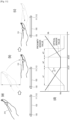
- the graph of FIG. 6 shows relative changes of the proximity sensor value and the optical sensor value as the hand 310 moves from the left toward the right of the electronic apparatus 100.
- a proximity sensor value gradually decreases as the hand 310 moves from the left toward the right of the electronic apparatus 100, reaches a minimum value Ma at a first point in time a1, maintains the minimum value Ma, and increases at a second point in time a2.
- the minimum value Ma refers to a proximity sensor value corresponding to the shortest distance between the hand 310 and the proximity sensor 111.
- the optical sensor value gradually increases, reaches a maximum value Mb at a third point in time b1 when the hand 310 covers the optical sensor 112, maintains the maximum value Mb, and decreases at a fourth point in time b2.
- the maximum value Mb refers to an optical sensor value corresponding to the lowest intensity of light blocked by the hand 310.
- the electronic apparatus 100 may also determine whether the second point in time a2 at which the proximity sensor value increases from the minimum value Ma precedes the fourth point in time b2 at which the optical sensor value decreases from the maximum value Mb. That is, when the second point in time a2 precedes the fourth point in time b2, the electronic apparatus 100 determines that a motion is made in a direction from the left toward the right of the electronic apparatus 100.
- FIG. 7 shows a user's general operation of moving the hand 310 from the right to the left of the electronic apparatus 100 as divided into (a) and (b).
- (a) in FIG. 7 illustrates that the hand 310 of the user is positioned at the right of the electronic apparatus 100
- (b) in FIG. 7 illustrates that the hand 310 is positioned at the left of the electronic apparatus 100 as moved from the right.
- the graph of FIG. 7 shows relative changes of the proximity sensor value and the optical sensor value as the hand 310 moves from the right to the left of the electronic apparatus 100.
- the first point in time a1 at which the proximity sensor value reaches the minimum value Ma follows the third point in time b1 at which the optical sensor value reaches the maximum value Mb. That is, when the first point in time a1 lags behind the third point in time b1, the electronic apparatus 100 determines that a motion is made in a direction from the right to the left of the electronic apparatus 100.
- the electronic apparatus 100 may also determine whether the second point in time a2 at which the proximity sensor value increases from the minimum value Ma follows the fourth point in time b2 at which the optical sensor value decreases from the maximum value Mb. That is, when the second point in time a2 lags behind the fourth point in time b2, the electronic apparatus 100 determines that a motion is made in a direction from the right to the left of the electronic apparatus 100.
- the electronic apparatus 100 determines the direction of the user motion based on the change in the proximity sensor value and the optical sensor value.
- the electronic apparatus 100 is convenient for a user because the electronic apparatus 100 determines the direction of the user motion and the user does not have to move his/her eyes, which have been focused on the external apparatus 200 to be remotely controlled, to the electronic apparatus 200.
- FIG. 8 illustrates positions where sensors provided in the electronic apparatus in FIG. 1 are arranged.
- the proximity sensor 111 and the optical sensor 112 are arranged leaving a predetermined distance D in the widthwise direction, but there are no limits to the distance D and the arrangement direction. Alternatively, various distances D and arrangement directions are possible.
- the proximity sensor 111 and the optical sensor 112 are arranged in the widthwise direction of the electronic apparatus 100 as shown in (a) of FIG. 8 , but the proximity sensor 111 and the optical sensor 112 may be respectively arranged at the left and the right of the sound output unit 150. According to an alternative embodiment, the proximity sensor 111 may be arranged at the right and the optical sensor 112 may be arranged at the left.
- a predetermined distance D between the proximity sensor 111 and the optical sensor 112 is larger than those of FIG. 6 and 7 . As the distance D between the proximity sensor 111 and the optical sensor 112 increases, it is easier to determine whether the first point in time a1 precedes or follows the third point in time b1 and whether the second point in time a2 precedes or follows the fourth point in time b2.
- the proximity sensor 111 and the optical sensor 112 may be arranged in the lengthwise direction of the electronic apparatus 100, and the proximity sensor 111 and the optical sensor 112 may be respectively the left and the right of the display 120. As an alternative embodiment, it may be designed to arrange the proximity sensor 111 at the right and arrange the optical sensor 112 at the left.
- a predetermined distance D between the proximity sensor 111 and the optical sensor 112 is larger than that in (a) of FIG. 8 , and therefore it is easier to determine whether the first point in time a1 precedes or follows the third point in time b1 and whether the second point in time a2 precedes or follows the fourth point in time b2.
- FIG. 9 illustrates an example of guiding an orientation direction of the electronic apparatus in FIG. 1 .
- the guiding method may include a method of displaying a UI through the display 120 or a method of outputting a sound through the sound output unit 150.
- a Ul 123 where the upper and lower sides of the electronic apparatus 100 are oriented toward the external apparatus 200 may be displayed on the display 120.
- the Ul 123 may guide a user to correctly orient the electronic apparatus 100.
- a UI 311 indicating a motion direction recognizable by the electronic apparatus 100 may be further displayed to guide a user to correctly make the motion.
- the proximity sensor 111 and the optical sensor 112 are arranged along the lengthwise direction of the electronic apparatus 100, a UI 123 where the left and right sides of the electronic apparatus 100 are oriented toward the external apparatus 200 may be displayed on the display 120. As necessary, a UI 311 indicating the motion direction recognizable by the electronic apparatus 100 may be further displayed.
- FIGS. 10 and 11 illustrate examples that the electronic apparatus in FIG. 1 recognizes a user motion in accordance with patterns of a sensor value in the second mode.
- the proximity sensor 111 and the optical sensor 112 of are arranged along the widthwise direction of the electronic apparatus 100, but not limited thereto.
- FIG. 10 shows a user's general operation of moving the hand 310 from the bottom toward the top of the electronic apparatus 100 as divided into (a) and (b).
- (a) of FIG. 10 illustrates that the hand 310 of the user is positioned at the bottom of the electronic apparatus 100
- (b) of FIG. 10 illustrates that the hand 310 is positioned at the top of the electronic apparatus 100 as moved from the bottom.
- the graph of FIG. 10 shows relative changes of the proximity sensor value and the optical sensor value as the hand 310 moves from the bottom toward the top of the electronic apparatus 100.
- a proximity sensor value gradually decreases as the hand 310 moves from the bottom toward the top of the electronic apparatus 100, and maintains the minimum value Ma from the first point in time a1.
- the optical sensor value gradually increases, and maintains the maximum value Mb from the third point in time b12 when the hand 310 covers the optical sensor 112.
- the first point in time a1 may be equal to the third point in time b12.
- the electronic apparatus 100 may determines that the motion direction is oriented from the bottom toward the top of the electronic apparatus 100 when the first point in time a1 is equal to the third point in time b12.
- the profile of the hand 310 is so irregular that the first point in time a1 and the third point in time b12 may be changed. For example, even when the hand 310 moves from the bottom toward the top of the electronic apparatus 100, the third point in time b11 preceding the first point in time a1 or the third point in time b13 following the first point in time a1 may be detected.
- the motion direction may be determined based on the patterns of the sensor values.
- the optical sensor value in the graph of FIG. 6 includes a first section w1 where the optical sensor value increases before the third point in time b1 at which the maximum value Mb starts, a second section w2 where the maximum value Mb is maintained, and a third section w3 where the optical sensor value decreases after the fourth point in time b2 at which the maximum value Mb ends.
- the optical sensor value includes the first section w1 where the optical sensor value increases before the third point in time b12 at which the maximum value Mb starts, and a second section w2 where the maximum value Mb is maintained.
- the optical sensor value does not include the third section w3 where the optical sensor value decreases after the fourth point in time b2 at which the maximum value Mb ends.
- the electronic apparatus 100 may determine that the hand 310 moves from the bottom toward the top based on the pattern of the optical sensor value including the first section w1 and the second section w2, even though it is unclear whether the first point in time a1 precedes or follows the third point in time b12 as they are changed.
- the electronic apparatus 100 may determine that the hand 310 moves from the left toward the right based on the pattern of the optical sensor value that includes the third section w3 as well as the first section w1 and the second section w2.
- the electronic apparatus 100 can determine the motion direction based on the pattern of the proximity sensor value. That is, the electronic apparatus 100 determines that the hand 310 moves from the bottom toward the top when the pattern of the proximity sensor value does not include the section, in which the proximity sensor value increases from the minimum value Ma after the second point in time a2, as shown in the graph of FIG. 6 .
- FIG. 11 shows a user's general operation of moving the hand 310 from the top toward the bottom of the electronic apparatus 100 as divided into (a), (b) and (c).
- (a) of FIG. 11 illustrates that the hand 310 of the user is positioned at the bottom of the electronic apparatus 100
- (b) of FIG. 11 illustrates that the hand 310 is positioned at the top as moved from the bottom.
- (a) and (b) of FIG. 11 illustrate that the general operation of moving the hand 310 from the bottom toward the top, which will be a precondition for moving the hand 310 from the top toward the bottom.
- FIG. 11 shows a user's general operation of moving the hand 310 from the top toward the bottom of the electronic apparatus 100 as divided into (a), (b) and (c).
- FIG. 11 involve vertical movement of the hand 310 having a height difference H greater than or equal to a predetermined threshold while the hand 310 moves from the bottom toward the top, the hand 310, whereas (a) and (b) of FIG. 10 illustrate horizontal movement of the hand 310 having a height difference H less than or equal to the predetermined threshold.
- (c) of FIG. 11 illustrates that the hand 310 is positioned at the bottom as moved from the top. Further, the graph of FIG. 11 shows relative changes of the proximity sensor value and the optical sensor value as the hand 310 moves from the bottom toward the top of the electronic apparatus 100.
- the proximity sensor value gradually decreases as the hand 310 moves from the bottom toward the top of the electronic apparatus 100, reaches the minimum value Ma at the first point in time a1, maintains the minimum value Ma, and starts increasing at the second point in time a2.
- the optical sensor value gradually increases, reaches the maximum value Mb at the third point in time b1 when the hand 310 covers the optical sensor 112, maintains the maximum value Mb, and starts decreasing at the fourth point in time b2.
- the first point in time a1 may be equal to the third point in time b1, or the second point in time a2 may be equal to the fourth point in time b2.
- the electronic apparatus 100 may determine that the motion direction is oriented from the bottom toward the top of the electronic apparatus 100.
- the profile of the hand 310 is so irregular that the third point in time b1 and the fourth point in time b2 may be respectively changed with regard to the first point in time a1 and the second point in time a2.
- the electronic apparatus 100 may determine the motion direction based on the patterns of the sensor values.
- the optical sensor value in the graph of FIG. 6 increases by a first change rate c1 in the first section w1
- the optical sensor value in the graph of FIG. 10 increases by a second change rate c2 in the first section w1.
- the hand 310 in FIGS. 6 and 10 shows the horizontal movement of which the height difference H is less than or equal to the predetermined threshold
- the hand 310 in FIG. 11 involves vertical movement of which the height difference H is greater than or equal to the predetermined threshold. Therefore, the optical sensor value in the graph of FIG. 11 increases by a third change rate c3 lower than the first change rate c1 or the second change rate c2.
- the electronic apparatus 100 may determine that the hand 310 moves from the top toward the bottom based on the pattern of the optical sensor value showing a gentle gradient in the first section w1. Likewise, the electronic apparatus 100 may determine that the hand 310 moves from the top to the bottom based on the proximity sensor value different in the pattern from the proximity sensor value of FIGS. 6 and 10 .
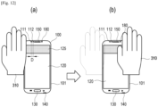
- FIG. 12 illustrates an example that the electronic apparatus in FIG. 1 recognizes a user motion based on a change in a sensor value of a control image.
- the electronic apparatus 100 displays the control image 128 on the display 120 when entering the second mode in response to various events.
- the control image 128 may have a predetermined brightness or color.
- the processor 190 may display a control image 125 with a predetermined color on the display 120, and sense a change or a change pattern in a sensor value of a light reflected as the hand 310 moves from (a) to (b).
- the control image 125 may be displayed on any area of the display 120, but it is preferable that the control image 125 is displayed on an area near to the optical sensor 112.
- a process, in which the electronic apparatus 100 determines the moving direction of the hand 310 based on the change or changing pattern in the proximity sensor value and the optical sensor value of the reflected light is equivalent to those described with reference to FIGS. 6 , 7 , 10 , and 11 , and thus repetitive descriptions will be avoided.
- the control image 125 having a predetermined color is displayed on the display 120, it is easy to remotely control the external apparatus 200 without being affected by surrounding environments.
- FIG. 13 illustrates an embodiment as an alternative to the control image of FIG. 12 .
- the electronic apparatus 100 in FIG. 12 displays the control image 125 having one color on a certain area of the display 120, but the electronic apparatus 100 of FIG. 13 displays at least two images 126 and 127 different in color on a certain area of the display 120.
- FIG. 13 illustrates that a first control image 126 having a first color is displayed at the left of a second control image 127 having a second color along the widthwise direction of the electronic apparatus 100.
- the first control image 126 and the second control image 127 may be displayed on an area adjacent to the optical sensor 112 along the arrangement direction of the proximity sensor 111 and the optical sensor 112.
- the optical sensor 112 may sense a first color value based on the first control image 126 and a second color value based on the second control image 127.
- the optical sensor 112 may be provided as a single sensor capable of sensing two or more colors, or may be provided as two or more optical sensors for sensing different colors.
- the graph of FIG. 13 shows relative changes in a first color value and a second color value as the hand 310 moves from the left toward the right of the electronic apparatus 100, for example, from (a) to (b).
- the first color value gradually increases as the hand 310 moves from the left toward the right of the electronic apparatus 100, reaches the maximum value Ma at the first point in time a1, maintains the maximum value Ma, and starts decreasing at the second point in time a2.
- the maximum value Ma may refer to the first color value corresponding to the maximum intensity of the first color reflected from the hand 310.
- the second color value also gradually increases, reaches the maximum value Mb at the third point in time b1, maintains the maximum value Mb and starts decreasing at the fourth point in time b2.
- the maximum value Mb may refer to the second color value corresponding to the maximum intensity of the second color reflected from the hand 310.
- the electronic apparatus 100 may determine that the motion direction is oriented from the left toward the right of the electronic apparatus 100. To more correctly determine the motion direction, the electronic apparatus 100 may also determine whether the second point in time a2 precedes the fourth point in time b2.
- FIG. 14 illustrates an example that the electronic apparatus in FIG. 1 recognizes a user motion in accordance with a change in the second sensor value of a sound sensor and an optical sensor.
- the electronic apparatus 100 of FIG. 14 employs a sound sensor 140 instead of the proximity sensor 111 used by the electronic apparatus 100 of FIG. 6 , 7 , 10 , and 11 .
- the sound sensor 140 senses whether a sound output through the sound output unit 150 is changed in strength by movement of the hand 310.
- a sound sensor value gradually decreases as the hand 310 moves from the left toward the right of the electronic apparatus 100, for example from (a) to (b), reaches the minimum value Ma at the first point in time a1, maintains the minimum value Ma, and starts increasing at the second point in time a2.
- the minimum value Ma refers to a sound sensor value corresponding to the maximum sound strength between the hand 310 and sound sensor 140.
- the optical sensor value gradually increases, reaches the maximum value Mb at the third point in time b1 when the hand 310 covers the optical sensor 112, maintains the maximum value Mb, and starts decreasing at the fourth point in time b2.
- the electronic apparatus 100 may determine that the motion direction is oriented from the left toward the right of the electronic apparatus 100.
- a process, in which the electronic apparatus 100 determines the moving direction of the hand 310 based on the change or changing pattern in the sound sensor value and the optical sensor value, is equivalent to those described with reference to FIGS. 5 , 6 , 9 , and 10 , and thus repetitive descriptions thereof will be avoided.
- a program command that can be implemented in various computers, and recorded in a computer readable medium.
- a computer readable medium may include a program command, a data file, a data structure or the like, or combination thereof.
- the computer readable medium may be stored in a volatile or nonvolatile storage such as a ROM or the like, regardless of whether it is deletable or rewritable, for example, a RAM, a memory chip, a device or integrated circuit (IC) like memory, or an optically or magnetically recordable or machine (e.g., a computer)-readable storage medium, for example, a compact disk (CD), a digital versatile disk (DVD), a magnetic disk, a magnetic tape or the like.
- a memory which can be included in a mobile terminal, is an example of the machine-readable storage medium suitable for storing a program having instructions for realizing the exemplary embodiments.
- the program command recorded in this storage medium may be specially designed and configured according to the exemplary embodiments, or may be publicly known and available to those skilled in the art of computer software.
- the electronic apparatus recognizes the direction of the user motion for controlling the external apparatus without using a separate motion recognition sensor and performs a function of controlling the external apparatus, and it is more convenient for a user because the user can control the external apparatus while looking at the external apparatus.
Landscapes
- Engineering & Computer Science (AREA)
- Human Computer Interaction (AREA)
- Signal Processing (AREA)
- General Engineering & Computer Science (AREA)
- Theoretical Computer Science (AREA)
- Computer Networks & Wireless Communication (AREA)
- Physics & Mathematics (AREA)
- General Physics & Mathematics (AREA)
- Multimedia (AREA)
- Environmental & Geological Engineering (AREA)
- User Interface Of Digital Computer (AREA)
Description
- Apparatuses and methods consistent with the exemplary embodiments relate to an electronic apparatus and a control method thereof, and more particularly to an electronic apparatus which controls an external apparatus in response to a received user input and a control method thereof.
- With diversification of functions, a smart phone and the like electronic apparatus have already become necessities for modern people. As one of the functions, there is a function of using the electronic apparatus to control another electronic apparatus (hereinafter, referred to as an 'external apparatus'). By the function of controlling the external apparatus, a user makes an input to the electronic apparatus and controls the external apparatus through the electronic apparatus.
- For example, when various functions the external apparatus has are displayed on a screen of the electronic apparatus in the form of a graphic user interface (GUI), a user makes a touch input or the like for selecting one of various functions displayed as the GUI while looking at the screen of the electronic apparatus. Then, the electronic apparatus recognizes a user's touch input received through the touch screen, and controls the external apparatus to implement a function corresponding to the GUI selected by the recognized touch input.
-
US 2016/004317 A1 describes a control method applied to an electronic device on which at least two sensing units are arranged.WO 2016/113740 A1 describes methods and systems for controlling electronic devices through digital signal processor and handler logic.US 2017/344328 A1 describes a user terminal device, a method of controlling the user terminal device, and a system for providing content. - The user terminal device includes a communicator configured to communicate with a display device, a detector configured to detect a distance between the user terminal device and the display device, a plurality of sensors configured to receive input of a user command, and a controller. The plurality of sensors comprise a proximity sensor configured to receive a user command corresponding to a detection of a gesture of a user who is hovering with a finger above a finger hovering area of the proximity sensor. The controller is configured to activate the proximity sensor in response to a detection that the user terminal device is within a predetermined distance with respect to the display device, thereby allowing the user to control an operation of the display device based on a gesture detected by the proximity sensor of the user terminal device. To ensure easy manipulation of the user terminal device even in a dark indoor place, the display device is configured to sense the surrounding illuminance and send a brightness control signal to the user terminal device when the sensed illuminance is less than a preset threshold value. The user terminal device controls a backlight in a housing of the user terminal device when the brightness control signal is received.
-
US 2018/018450 A1 describes an electronic device including a biometric sensor that identifies an input received.US 2010/295773 A1 describes an electronic device having an infrared sensing assembly for detecting and interpreting gestures. - When a user input is made by touching a GUI displayed on a touch screen of an electronic apparatus, as it is sometimes the case in the prior art, a user has to look at the screen of the electronic apparatus in order to make an input in the middle of watching the screen of the external apparatus, and it is thus inconvenient for the user since his/her eyes are moved from the external apparatus to the electronic apparatus. To solve such a problem, if a free motion type of user input is made instead of the touch input using the GUI, the electronic apparatus additionally needs a motion recognition sensor to recognize a user motion and therefore causes another problem of increasing costs.
- There is provided an electronic apparatus in accordance with
claim 1 and a method of controlling an electronic apparatus in accordance with claim 7. Other aspects of the invention are set forth in the dependent claims. - The above and/or the aspects will become apparent and more readily appreciated from the following description of exemplary embodiments, taken in conjunction with the accompanying drawings, in which:
-
FIG. 1 illustrates an example that an electronic apparatus according to one embodiment of the disclosure controls an external apparatus; -
FIG. 2 is a block diagram of the electronic apparatus inFIG. 1 ; -
FIG. 3 is a flowchart of a control method of the electronic apparatus inFIG. 1 ; -
FIG. 4 illustrates an example that the electronic apparatus inFIG. 1 operates by switching over from a first mode to a second mode; -
FIG. 5 illustrates an example in accordance with the present invention that the electronic apparatus inFIG. 1 displays a control image -
FIGS. 6 and7 illustrate examples that the electronic apparatus inFIG. 1 recognizes a user motion in accordance with a change in a sensor value; -
FIG. 8 illustrates positions where sensors provided in the electronic apparatus inFIG. 1 are arranged; -
FIG. 9 illustrates an example of guiding an orientation direction of the electronic apparatus inFIG. 1 ; -
FIGS. 10 and11 illustrate examples that the electronic apparatus inFIG. 1 recognizes a user motion in accordance with patterns of a sensor value in the second mode; -
FIG. 12 illustrates an example that the electronic apparatus inFIG. 1 recognizes a user motion based on a change in a sensor value of a control image; -
FIG. 13 illustrates an embodiment as an alternative to the control image ofFIG. 12 ; and -
FIG. 14 illustrates an example that the electronic apparatus inFIG. 1 recognizes a user motion in accordance with a change in the second sensor value of a sound sensor and an optical sensor. - Below, embodiments of the disclosure will be described in detail with reference to accompanying drawings. In the description of the following embodiments, elements illustrated in the accompanying drawings will be referenced, and like numerals or symbols set forth in the drawings refer to like elements having substantially the same function. In the disclosure, at least one among a plurality of elements refers to not only all the plurality of elements but also both each one of the plurality of elements excluding the other elements and a combination thereof.
-
FIG. 1 illustrates an example that an electronic apparatus according to one embodiment of the disclosure controls an external apparatus.FIG. 1 is given on the assumption that a user controls anexternal apparatus 200 through anelectronic apparatus 100 while looking animage 210 displayed on theexternal apparatus 200. Theexternal apparatus 200 may be a television (TV) or the like display apparatus, but may be actualized without limitation in the disclosure. For example, theexternal apparatus 200 may be actualized by various apparatus such as a computer, a multimedia player, an electronic frame, a digital billboard, a large format display (LFD), a digital signage, a set-top box, a refrigerator, etc. - The
electronic apparatus 100 refers to a separate apparatus from theexternal apparatus 200, and may for example be actualized by a smart phone, a smart pad, a wearable smart device, a mobile phone, a tablet personal computer (PC), an electronic book terminal, a personal digital assistant (PDA), a portable multimedia player (PMP), etc. without limitation. - The
electronic apparatus 100 may perform various function in accordance with its actualization forms. For example, theelectronic apparatus 100 may perform not only controlling theexternal apparatus 200 but also various functions such as playing back content, making a voice call, making a video call, capturing a moving picture, capturing a still picture, sending a message, browsing Internet, etc. - To perform the foregoing functions, the
electronic apparatus 100 uses a sensor value obtained by a sensor. For example, theelectronic apparatus 100 may perform the function of capturing a still picture by executing a photographing application. Theelectronic apparatus 100 may control a focus or exposure of a camera on the basis of a proximity sensor value from a proximity sensor and an optical sensor value from an optical sensor. Like this, a mode where theelectronic apparatus 100 employs the proximity sensor, the optical sensor and the like sensor and performs its own functions such as the function of capturing a still picture, etc. will be called a first mode. In the first mode according to an exemplary embodiment, various functions such as playing back content, making a voice call, making a video call, capturing a moving picture, capturing a still picture, sending a message, browsing Internet, etc. may be performed. - The
electronic apparatus 100 according to an exemplary embodiment controls the functions of theexternal apparatus 200 in response to a user input. A mode where theelectronic apparatus 100 controls the functions of theexternal apparatus 200 except the foregoing functions will be called a second mode. In the second mode, theelectronic apparatus 100 may recognize a user input for controlling the functions of theexternal apparatus 200 through the plurality of sensors. - In the second mode, the user input includes a user motion. That is, the
electronic apparatus 100 employs a plurality of sensors, which are used in carrying out its own functions in the first mode, to recognize the user motion for controlling theexternal apparatus 200 in the second mode. As an example of the plurality of sensors according to an exemplary embodiment, the proximity sensor and the optical sensor are used for the functions of theelectronic apparatus 100 to set a photographing condition in the first mode, but used to recognize a user motion for controlling theexternal apparatus 200 in the second mode. - In more detail, it will be assumed that the user motion is for example activity of a hand among body parts, and a motion of moving a user's hand from left to right is a control command for turning up the volume of the
external apparatus 200. - When a user makes a motion of moving a hand from left to right with respect to the
electronic apparatus 100 in the second mode, theelectronic apparatus 100 recognizes that the motion is made from left to right on the basis of the sensor values of the proximity sensor and the optical sensor. In an example not covered by the claims, theelectronic apparatus 100 transmits information about the recognized motion to theexternal apparatus 200, and theexternal apparatus 200 determines the control command based on the received information about the motion, and performs an operation of turning the volume up in response to the control command. In accordance with the claimed invention, theelectronic apparatus 100 transmits the control command, e.g., for turning up the volume of theexternal apparatus 200 to theexternal apparatus 200 on the basis of the information about the recognized motion, and theexternal apparatus 200 may perform the operation of turning up the volume in response to the received control command. - The motion in this embodiment is not limited to a hand motion, and the
electronic apparatus 100 may sense a motion based on another body part such as a user's face, arm, body, leg, etc. Further, theelectronic apparatus 100 may be designed to recognize directions of various motions, and different control commands may be respectively assigned to the directions of the motions. For example, theelectronic apparatus 100 may recognize left/right directions, up/down directions, a diagonal direction, a perpendicularly approaching/receding direction, etc. with respect to theelectronic apparatus 100. Corresponding to the directions of the motions of theelectronic apparatus 100, various control commands for power on/off, channel up/down, volume up/down, content selection, content downloading, content play, content stop, content deletion, etc. in theexternal apparatus 200. - Thus, the
electronic apparatus 100 according to an exemplary embodiment is more convenient for a user because the user can input a control command based on a motion without looking at the screen of theelectronic apparatus 100 for a touch input and thus control theexternal apparatus 200 while watching theexternal apparatus 200. Further, the plurality of sensors used to carry out the functions of theelectronic apparatus 100 are employed in recognizing the user motion for controlling theexternal apparatus 200, and thus costs are reduced because there are no needs of separate motion recognition sensor for recognizing the user motion. -
FIG. 2 is a block diagram of the electronic apparatus inFIG. 1 . Theelectronic apparatus 100 inFIG. 1 includes adisplay 120, acommunicator 160, aprocessor 190, and asensor unit 110, and may include auser input unit 130, asound receiver 140, asound output unit 150, astorage 170, and animage capturer 180. However, theelectronic apparatus 100 may be designed to exclude at least one optional element from the elements shown inFIG. 2 or add another element not shown inFIG. 2 - The
sensor unit 110 includes a plurality of sensors for obtaining various sensor values related to theelectronic apparatus 100. For example, thesensor unit 110 may include animage sensor 180, aproximity sensor 111, anoptical sensor 112, a sound sensor, a temperature sensor, a humidity sensor, a pressure sensor, an impact sensor, a depth sensor, a global positioning system (GPS) sensor, a gyro sensor, etc. - The
image sensor 180 obtains a capture image of a front direction thereof. Theimage sensor 180 may be actualized by a camera of a complementary metal oxide semiconductor (CMOS) or a charge coupled device (CCD). There may be two ormore image sensors 180. - The
proximity sensor 111 is configured to sense a distance from a surrounding object. For example, when theproximity sensor 111 employs a time-of-flight method for measuring an infrared signal, theelectronic apparatus 100 measures a distance from a moving object by measuring a delay time until an output infrared signal is reflected and returns from the object. When theproximity sensor 111 employs a magnetic measurement method of an object, a distance from the moving object is measured based on a magnetic field, magnetic intensity, a magnetic field direction, change in magnetic force, etc. However, there are no limits to the kind of theproximity sensor 111, and theproximity sensor 111 may be actualized by a magnetic saturation type, a high-frequency oscillation type, a differential coil, electrostatic capacitance type, etc. - The
optical sensor 112 measures the intensity and amount of light around theelectronic apparatus 100. Theoptical sensor 112 may for example be actualized by lead sulfide (PbS) or cadmium sulfide (CdS) photoconductive cells. According to an exemplary embodiment, theimage sensor 180 may serve as theoptical sensor 112. - The
display 120 displays an image based on an image signal. Thedisplay 120 may be actualized by a liquid crystal display, a thin film transistor-liquid crystal display, an organic light-emitting diode, a flexible display, a 3-dimensional (3D) display, etc. Thedisplay 120 may be also actualized by a touch screen together with theuser input unit 130 for receiving a touch input. - The
user input unit 130 receives a user input for controlling the operations of theelectronic apparatus 100. Theuser input unit 130 may include a touch screen, a key pad, a dome switch, a touch pad (static pressure/electrostatic), a jog wheel, a jog switch, a finger mouse, etc. - The
sound receiver 140 receives and processes a sound signal into an electric audio signal. Thesound receiver 140 may use various noise removal algorithms to remove noise generated while receiving a sound signal. Thesound receiver 140 may be actualized by a microphone, and the microphone may be used as the sound sensor. Thesound output unit 150 may output a processed audio signal to the outside. Thesound output unit 150 may be actualized by a loudspeaker. - The
communicator 160 may perform wireless communication with theexternal apparatus 200 through various communication standards. For example, thecommunicator 160 may perform wireless communication based on Wi-Fi, Bluetooth, ZigBee, Wi-Fi Direct (WFD), ultra-wideband (UWB), infrared Data Association (IrDA), Bluetooth low energy (BLE), near field communication (NFC), etc. - The
communicator 160 may further include amobile communication mobile 161 for transmitting and receiving a wireless signal to and from at least one of a base station, an external terminal and a server on a mobile communication network, awireless Internet module 162 for wireless connection with the Internet, a near field communication module for near field communication, a GPS module, etc. - The
storage 170 may be configured to store data, a program, or an application for various functions to be implemented by theelectronic apparatus 100. Thestorage 170 may include a storage medium of at least one type among a flash memory type, a hard disk type, a multimedia card micro type, a card type memory (e.g. a secure digital (SD) or extreme digital (XD) memory, etc.), a random access memory (RAM), and a read only memory (ROM). Thestorage 170 may be actualized by a web storage that operates on the Internet. - The
processor 190 may generally control the elements of theelectronic apparatus 100. Theprocessor 190 performs the functions of theelectronic apparatus 100 based on the sensor value sensed by thesensor unit 110 in the first mode. Further, theprocessor 190 performs a control function to recognize a user motion, and outputs a control command indicating the direction of the recognized motion to theexternal apparatus 200, based on the sensor value sensed by thesensor unit 110 in the second mode different from the first mode. - The
processor 190 executes a control program (or an instruction) for generally controlling the elements as described above. Theelectronic apparatus 100 may include a nonvolatile memory in which the control program is installed, and a volatile memory into which at least a part of the installed control program is loaded. Further, such a control program may be also stored in another electronic apparatus besides theelectronic apparatus 100. - The control program may include a program(s) actualized in the form of at least one among a basis input/output system (BIOS), a device driver, an operating system, a firmware, a platform, and an application. According to an exemplary embodiment, the application may be previously installed or stored when the
electronic apparatus 100 is manufactured, or may be installed based on application data received from the outside when it is used in the future. The application data may for example be downloaded from an application market and the like external server. Such an external server is an example of a computer program product, but not limited to this example. - The
electronic apparatus 100 may further include a signal processor and a power supply. The signal processor applies various processes to a received video or audio signal so that thedisplay 120 or thesound output unit 150 can output an image or a sound. The signal processor may include a hardware processor actualized by a chipset, a circuit, a buffer, etc. mounted on to a printed circuit board, and may also be designed as a system on chip (SoC). Further, the power supply may receive external power or internal power and supply power necessary for the elements of theelectronic apparatus 100 under control of theprocessor 190. -
FIG. 3 is a flowchart of a control method of the electronic apparatus inFIG. 1 . The control method of the electronic apparatus shown inFIG. 3 may be performed as theprocessor 190 of theelectronic apparatus 100 shown inFIG. 2 executes at least one control program. In the following description, unless otherwise mentioned, the operation of theprocessor 190 is an operation performed by executing the control program. - First, the
processor 190 performs an operation of theelectronic apparatus 100 based on the sensor value sensed though thesensor unit 110 including the plurality of sensors in the first mode (S310). Further, theprocessor 190 identifies a direction of a user motion based on a sensor value sensed through thesensor unit 110, and outputs a control command corresponding to the direction of the determined motion to theexternal apparatus 200, in the second mode (S320). - In the operations S310 and S320, the
processor 190 may identify whether a current mode is the first mode or the second mode in accordance with whether a preset event occurs or not. For example, theprocessor 190 identifies that the current mode is the first mode when the preset event has not occurred yet. When the present event occurs in the first mode, theprocessor 190 identifies that the current mode is the second mode. That is, theelectronic apparatus 100 may switch over to the second mode and operate in the second mode in response to the occurrence of the preset event while operating in the first mode. -
FIG. 4 illustrates an example that the electronic apparatus inFIG. 1 operates by switching over from a first mode to a second mode. InFIG. 4 , it will be assumed that theexternal apparatus 200 is displaying theimage 210, and auser 300 wants to control the display of theimage 210 in theexternal apparatus 200. Further, it will be also assumed that theelectronic apparatus 100 carries out an operation in the first mode. - The operation in the first mode may for example include not only an operation for providing a function to be positively usable by the
user 300, such as playing back content, making a call, capturing an image, sending a message, browsing the Internet, etc., but also an operation for providing a function not to be positively usable by theuser 300, such as a standby mode of a smart phone, etc. - The
processor 190 determines whether the preset event occurs while operating in the first mode. The present event in this embodiment may for example include that theuser 300 of theexternal apparatus 200 moves close to theelectronic apparatus 100 within a predetermined distance from theelectronic apparatus 100. - For example, when the
user 300 moves toward theexternal apparatus 200 while taking theelectronic apparatus 100 so as to watch theimage 210 of theexternal apparatus 200, theprocessor 190 identifies that theexternal apparatus 200 approaches theelectronic apparatus 100 within a predetermined distance from theelectronic apparatus 100 on the basis of information obtained through thecommunicator 160 or the like. - Alternatively, the preset event may include that the
electronic apparatus 100 is connected for communication with theexternal apparatus 200. A communication method between theelectronic apparatus 100 and theexternal apparatus 200 may for example be Wi-Fi, Bluetooth, etc. For example, when theuser 300 moves close to theexternal apparatus 200 while taking theelectronic apparatus 100, theprocessor 190 controls thecommunicator 160 to connect with theexternal apparatus 200 by a preset communication method such as Bluetooth, etc., and identifies that the preset event occurs based on the completion of such connection. - Alternatively, the preset event may include that the
user input unit 130 receives a command of entering the second mode from theuser 300. For example, theprocessor 190 may identify whether a received touch input, voice command, etc. corresponds to a command to enter the second mode in response to the touch input, the voice command, etc. received on the touch screen during the operation in the first mode. In this case, theprocessor 190 displays a UI including a menu item, which is to receive a command of theuser 300 to enter the second mode, on thedisplay 120, and identifies the preset event based on the touch input received through the menu item of the Ul. - Alternatively, the preset event may include that a request for entering the second mode is received from the
external apparatus 200 or anexternal server 400. For example, while theelectronic apparatus 100 performs the operation of the first mode as connected for communication with theexternal apparatus 200 or theexternal server 400, theprocessor 190 may identify whether a signal received from theexternal apparatus 200 or theexternal server 400 corresponds to a request for entering the second mode, based on the signal received from theexternal apparatus 200 or theexternal server 400 through thecommunicator 160. Theexternal apparatus 200 or theexternal server 400 may recognize a user's intention through the sensor or the like or receive a user's input, thereby transmitting a request signal for entering the second mode to theelectronic apparatus 100. - Alternatively, the preset event may include that the
external apparatus 200 displays apreset image 210. Thepreset image 210 displayed by theexternal apparatus 200 may for example be animage 210 of preset content or content from a preset category. For example, theprocessor 190 may identify that theexternal apparatus 200 displays thepreset image 210 based on information included in a signal received from theexternal apparatus 200 through thecommunicator 160. In this case, theexternal apparatus 200 may transmit a signal, which includes information about currently displayed content, to theelectronic apparatus 100. - Alternatively, the
processor 190 may identify whether theexternal apparatus 200 displays thepreset image 210 based on the information obtained by thesensor unit 110 such as theimage sensor 180, etc. - The preset event according to an exemplary embodiment is not limited to the foregoing examples, and may include various events besides the foregoing examples.
- According to one embodiment, the
processor 190 may identify that the preset event occurs based on an apparatus use history of a user. The apparatus use history of a user may for example be a use time, a use place, etc. of theelectronic apparatus 100 or theexternal apparatus 200. The preset event based on the apparatus use history may for example include that a user watches a TV in a certain place at a certain time. Further, the preset event according to an exemplary embodiment may be based on a user's daily life, such as a wake-up time, a bed time, etc. of a user. - According to an exemplary embodiment, the apparatus use history of the user or the information about a user's daily life may be stored in the
electronic apparatus 100 or may be stored in theexternal apparatus 200 or theexternal server 400. When the information is stored in theexternal apparatus 200 or theexternal server 400, theprocessor 190 may receive information from theexternal apparatus 200, theexternal server 400 or may receive a request for entering the second mode from theexternal apparatus 200 orexternal server 400 storing the information. - When it is identified that the preset event occurs during the operation of the first mode, the
processor 190 may switch over to the second mode and then operate. Specifically, theprocessor 190 may execute an application dedicated to control of the external apparatus in response to the occurrence of the preset event. The dedicated application according to an exemplary embodiment may be one of at least one control program as described above. - According to an exemplary embodiment, the
processor 190 may display aUI 121, which guides a control mode of theexternal apparatus 200 to a user, on thedisplay 120 when the preset event occurs. TheUI 121 may include items for allowing a user to select whether to execute the control mode of theexternal apparatus 200. When a user's touch input to execute the control mode is received through theUI 121, theprocessor 190 may execute the dedicated application and enter the second mode. -
FIG. 5 illustrates an example in accordance with the claimed invention that the electronic apparatus inFIG. 1 displays a control image Referring toFIG. 5 , theprocessor 190 controls thedisplay 120 to display an image (hereinafter, referred to as a "control image") for controlling theexternal apparatus 200 in response to entering the second mode. - According to an example not covered by the claims, the brightness or color of a
control image 128 may be previously determined. According to the claimed invention, the brightness or color of thecontrol image 128 varies depending on surrounding environments. Thecontrol image 128 serves to let a user intuitively know the position of theelectronic apparatus 100 without moving his/her eyes toward theelectronic apparatus 100, when the user makes a motion while watching thescreen 210 of theexternal apparatus 200 in order to control theexternal apparatus 200. Therefore, thecontrol image 128 according to the claimed invention is configured to have the brightness or corresponding color so that a user can easily estimate the position of theelectronic apparatus 100 while watching thescreen 210 of theexternal apparatus 200. - For example, the
processor 190 may control the brightness of thecontrol image 128 to be higher than intensity of surrounding illumination. Theprocessor 190 may identify the surrounding illumination based on information obtained by theimage sensor 180, theoptical sensor 112, etc. Thus, a user can easily estimate the position of theelectronic apparatus 100 based on thecontrol image 128 brighter than the surrounding illumination. - As an additional or alternative example, the
processor 190 may control the color of thecontrol image 128 to be distinguishable from the color of ambient light. Theprocessor 190 may identify the color of the ambient light based on information obtained by theimage sensor 180, theoptical sensor 112, etc. For example, theprocessor 190 may set a color complementary to the color of the ambient light as the color of thecontrol image 128. Therefore, a user can more easily estimate the position of theelectronic apparatus 100 based on thecontrol image 128 showing a contrast to the color of the ambient light. - In accordance with the claimed invention, the
processor 190 identifies the surrounding illumination or the color of the ambient light based on the brightness orcolor 211 of theimage 210 displayed on theexternal apparatus 200. Theprocessor 190 receives information about theimage 210 displayed on theexternal apparatus 200 from theexternal apparatus 200 through thecommunicator 160, and identifies the surrounding illumination or the color of the ambient light based on the received information. As an optional example, theprocessor 190 may change the brightness or color of thecontrol image 128 in accordance with change in the surrounding illumination or the color of the ambient light. As an optional example not covered by the claims, theprocessor 190 may set the brightness or color of thecontrol image 128 based on settings set up by a user. In this case, theprocessor 190 may control thedisplay 120 to display a UI including menu items for setting the brightness or color of thecontrol image 128, and set the brightness or color of thecontrol image 128 based on a user input received through the Ul. - The
processor 190 recognizes a user motion for controlling theexternal apparatus 200 based on a sensor value obtained by thesensor unit 110 in the second mode, and performs control to transmit information about the recognized user motion to theexternal apparatus 200. Below, an example that theelectronic apparatus 100 according to an exemplary embodiment recognizes the user motion based on the sensor value obtained by thesensor unit 110 will be described in detail. -
FIGS. 6 and7 illustrate examples that the electronic apparatus inFIG. 1 recognizes a user motion in accordance with a change in a sensor value. Theelectronic apparatus 100 includes acase 101 forming an outer appearance. Thecase 101 is provided as the front and rear of theelectronic apparatus 100, forming a space to accommodate the elements of theelectronic apparatus 100. - On the
case 101, there is provided thedisplay 120, and there may be provided theproximity sensor 111, theoptical sensor 112, theuser input unit 130, thesound receiver 140, thesound output unit 150, and theimage capturer 180. Alternatively, theelectronic apparatus 100 may be designed to exclude at least one optional element from or include an additional element to the elements provided on thecase 101 - The
proximity sensor 111 and theoptical sensor 112 of theelectronic apparatus 100 may be arranged leaving a predetermined distance D on thecase 101. Theproximity sensor 111 of theelectronic apparatus 100 may be arranged at the left of theoptical sensor 112 and spaced apart at a predetermined distance from theoptical sensor 112 in a widthwise direction. However, there are no limits to the arrangement or direction. Alternatively, the twosensors electronic apparatus 100, and theoptical sensor 112 may be also arranged at the left of theproximity sensor 111 as spaced apart at a predetermined distance D from theproximity sensor 111. - According to an exemplary embodiment, it will be assumed that the
proximity sensor 111 outputs a sensor value which decreases as the object approaches theproximity sensor 111 and thus a distance between theproximity sensor 111 and an object becomes shorter, and theoptical sensor 112 outputs a sensor value which increases as the object blocks out light incident to theoptical sensor 112 and thus the intensity of the light decreases. However, such sensing features of theproximity sensor 111 and theoptical sensor 112 are merely an example, and may be designed to conversely obtain sensor values. -
FIG. 6 shows a user's general operation of moving ahand 310 from the left toward the right of theelectronic apparatus 100 as divided into (a) and (b). (a) inFIG. 6 illustrates that thehand 310 of the user is positioned at the left of theelectronic apparatus 100, and (b) inFIG. 6 illustrates that thehand 310 is positioned at the right of theelectronic apparatus 100 as moved from the left. Further, the graph ofFIG. 6 shows relative changes of the proximity sensor value and the optical sensor value as thehand 310 moves from the left toward the right of theelectronic apparatus 100. - Referring to the graph of
FIG. 6 , a proximity sensor value gradually decreases as thehand 310 moves from the left toward the right of theelectronic apparatus 100, reaches a minimum value Ma at a first point in time a1, maintains the minimum value Ma, and increases at a second point in time a2. Here, the minimum value Ma refers to a proximity sensor value corresponding to the shortest distance between thehand 310 and theproximity sensor 111. - The optical sensor value gradually increases, reaches a maximum value Mb at a third point in time b1 when the
hand 310 covers theoptical sensor 112, maintains the maximum value Mb, and decreases at a fourth point in time b2. Here, the maximum value Mb refers to an optical sensor value corresponding to the lowest intensity of light blocked by thehand 310. - Due to difference in position between the
proximity sensor 111 and theoptical sensor 112, the first point in time a1 at which the proximity sensor value reaches the minimum value Ma precedes the third point in time b1 at which the optical sensor value reaches the maximum value Mb. That is, when the first point in time a1 precedes the third point in time b1, theelectronic apparatus 100 determines that a motion is made in a direction from the left toward the right of theelectronic apparatus 100. - To more accurately determine the direction of the user motion, the
electronic apparatus 100 may also determine whether the second point in time a2 at which the proximity sensor value increases from the minimum value Ma precedes the fourth point in time b2 at which the optical sensor value decreases from the maximum value Mb. That is, when the second point in time a2 precedes the fourth point in time b2, theelectronic apparatus 100 determines that a motion is made in a direction from the left toward the right of theelectronic apparatus 100. -
FIG. 7 shows a user's general operation of moving thehand 310 from the right to the left of theelectronic apparatus 100 as divided into (a) and (b). (a) inFIG. 7 illustrates that thehand 310 of the user is positioned at the right of theelectronic apparatus 100, and (b) inFIG. 7 illustrates that thehand 310 is positioned at the left of theelectronic apparatus 100 as moved from the right. Further, the graph ofFIG. 7 shows relative changes of the proximity sensor value and the optical sensor value as thehand 310 moves from the right to the left of theelectronic apparatus 100. - Referring to the graph of
FIG. 7 , due to difference in position between theproximity sensor 111 and theoptical sensor 112, the first point in time a1 at which the proximity sensor value reaches the minimum value Ma follows the third point in time b1 at which the optical sensor value reaches the maximum value Mb. That is, when the first point in time a1 lags behind the third point in time b1, theelectronic apparatus 100 determines that a motion is made in a direction from the right to the left of theelectronic apparatus 100. - To more accurately determine the direction of the user motion, the
electronic apparatus 100 may also determine whether the second point in time a2 at which the proximity sensor value increases from the minimum value Ma follows the fourth point in time b2 at which the optical sensor value decreases from the maximum value Mb. That is, when the second point in time a2 lags behind the fourth point in time b2, theelectronic apparatus 100 determines that a motion is made in a direction from the right to the left of theelectronic apparatus 100. - Like this, the
electronic apparatus 100 determines the direction of the user motion based on the change in the proximity sensor value and the optical sensor value. Thus, theelectronic apparatus 100 is convenient for a user because theelectronic apparatus 100 determines the direction of the user motion and the user does not have to move his/her eyes, which have been focused on theexternal apparatus 200 to be remotely controlled, to theelectronic apparatus 200. -
FIG. 8 illustrates positions where sensors provided in the electronic apparatus inFIG. 1 are arranged. InFIGS. 6 and7 , theproximity sensor 111 and theoptical sensor 112 are arranged leaving a predetermined distance D in the widthwise direction, but there are no limits to the distance D and the arrangement direction. Alternatively, various distances D and arrangement directions are possible. - For example, the
proximity sensor 111 and theoptical sensor 112 are arranged in the widthwise direction of theelectronic apparatus 100 as shown in (a) ofFIG. 8 , but theproximity sensor 111 and theoptical sensor 112 may be respectively arranged at the left and the right of thesound output unit 150. According to an alternative embodiment, theproximity sensor 111 may be arranged at the right and theoptical sensor 112 may be arranged at the left. - With this arrangement, a predetermined distance D between the
proximity sensor 111 and theoptical sensor 112 is larger than those ofFIG. 6 and7 . As the distance D between theproximity sensor 111 and theoptical sensor 112 increases, it is easier to determine whether the first point in time a1 precedes or follows the third point in time b1 and whether the second point in time a2 precedes or follows the fourth point in time b2. - Further, as shown in (b) of
FIG. 8 , theproximity sensor 111 and theoptical sensor 112 may be arranged in the lengthwise direction of theelectronic apparatus 100, and theproximity sensor 111 and theoptical sensor 112 may be respectively the left and the right of thedisplay 120. As an alternative embodiment, it may be designed to arrange theproximity sensor 111 at the right and arrange theoptical sensor 112 at the left. - With this arrangement, a predetermined distance D between the
proximity sensor 111 and theoptical sensor 112 is larger than that in (a) ofFIG. 8 , and therefore it is easier to determine whether the first point in time a1 precedes or follows the third point in time b1 and whether the second point in time a2 precedes or follows the fourth point in time b2. -
FIG. 9 illustrates an example of guiding an orientation direction of the electronic apparatus inFIG. 1 . When theelectronic apparatus 100 is switched over to the second mode, a preferred orientation direction of theelectronic apparatus 100 is guided in accordance with the arrangement of theproximity sensor 111 and theoptical sensor 112. The guiding method may include a method of displaying a UI through thedisplay 120 or a method of outputting a sound through thesound output unit 150. - According to an exemplary embodiment, as shown in (a) of
FIG. 9 , when theproximity sensor 111 and theoptical sensor 112 are arranged along the widthwise direction of theelectronic apparatus 100, aUl 123 where the upper and lower sides of theelectronic apparatus 100 are oriented toward theexternal apparatus 200 may be displayed on thedisplay 120. TheUl 123 may guide a user to correctly orient theelectronic apparatus 100. As necessary, aUI 311 indicating a motion direction recognizable by theelectronic apparatus 100 may be further displayed to guide a user to correctly make the motion. - Further, as shown in (b) of
FIG. 9 , theproximity sensor 111 and theoptical sensor 112 are arranged along the lengthwise direction of theelectronic apparatus 100, aUI 123 where the left and right sides of theelectronic apparatus 100 are oriented toward theexternal apparatus 200 may be displayed on thedisplay 120. As necessary, aUI 311 indicating the motion direction recognizable by theelectronic apparatus 100 may be further displayed. -
FIGS. 10 and11 illustrate examples that the electronic apparatus inFIG. 1 recognizes a user motion in accordance with patterns of a sensor value in the second mode. In theelectronic apparatus 100 ofFIG. 10 and11 , it will be assumed that theproximity sensor 111 and theoptical sensor 112 of are arranged along the widthwise direction of theelectronic apparatus 100, but not limited thereto. -
FIG. 10 shows a user's general operation of moving thehand 310 from the bottom toward the top of theelectronic apparatus 100 as divided into (a) and (b). (a) ofFIG. 10 illustrates that thehand 310 of the user is positioned at the bottom of theelectronic apparatus 100, and (b) ofFIG. 10 illustrates that thehand 310 is positioned at the top of theelectronic apparatus 100 as moved from the bottom. Further, the graph ofFIG. 10 shows relative changes of the proximity sensor value and the optical sensor value as thehand 310 moves from the bottom toward the top of theelectronic apparatus 100. - Referring to the graph of
FIG. 10 , a proximity sensor value gradually decreases as thehand 310 moves from the bottom toward the top of theelectronic apparatus 100, and maintains the minimum value Ma from the first point in time a1. The optical sensor value gradually increases, and maintains the maximum value Mb from the third point in time b12 when thehand 310 covers theoptical sensor 112. - Because the
proximity sensor 111 and theoptical sensor 112 are arranged along the widthwise direction of theelectronic apparatus 100, the first point in time a1 may be equal to the third point in time b12. In other words, theelectronic apparatus 100 may determines that the motion direction is oriented from the bottom toward the top of theelectronic apparatus 100 when the first point in time a1 is equal to the third point in time b12. - However, the profile of the
hand 310 is so irregular that the first point in time a1 and the third point in time b12 may be changed. For example, even when thehand 310 moves from the bottom toward the top of theelectronic apparatus 100, the third point in time b11 preceding the first point in time a1 or the third point in time b13 following the first point in time a1 may be detected. - In this case, the motion direction may be determined based on the patterns of the sensor values. Referring back to the graph of
FIG. 6 , in which thehand 310 moves from the left toward the right, in order to describe the case of identifying the motion direction based on the pattern of the optical sensor value, the optical sensor value in the graph ofFIG. 6 includes a first section w1 where the optical sensor value increases before the third point in time b1 at which the maximum value Mb starts, a second section w2 where the maximum value Mb is maintained, and a third section w3 where the optical sensor value decreases after the fourth point in time b2 at which the maximum value Mb ends. - On the other hand, referring to the graph of
FIG. 10 in which thehand 310 moves from the bottom toward the top, the optical sensor value includes the first section w1 where the optical sensor value increases before the third point in time b12 at which the maximum value Mb starts, and a second section w2 where the maximum value Mb is maintained. In other words, when thehand 310 moves from the bottom toward the top, the optical sensor value does not include the third section w3 where the optical sensor value decreases after the fourth point in time b2 at which the maximum value Mb ends. - That is, the
electronic apparatus 100 may determine that thehand 310 moves from the bottom toward the top based on the pattern of the optical sensor value including the first section w1 and the second section w2, even though it is unclear whether the first point in time a1 precedes or follows the third point in time b12 as they are changed. On the other hand, theelectronic apparatus 100 may determine that thehand 310 moves from the left toward the right based on the pattern of the optical sensor value that includes the third section w3 as well as the first section w1 and the second section w2. - In the same manner, the
electronic apparatus 100 can determine the motion direction based on the pattern of the proximity sensor value. That is, theelectronic apparatus 100 determines that thehand 310 moves from the bottom toward the top when the pattern of the proximity sensor value does not include the section, in which the proximity sensor value increases from the minimum value Ma after the second point in time a2, as shown in the graph ofFIG. 6 . -
FIG. 11 shows a user's general operation of moving thehand 310 from the top toward the bottom of theelectronic apparatus 100 as divided into (a), (b) and (c). (a) ofFIG. 11 illustrates that thehand 310 of the user is positioned at the bottom of theelectronic apparatus 100, (b) ofFIG. 11 illustrates that thehand 310 is positioned at the top as moved from the bottom. Here, (a) and (b) ofFIG. 11 illustrate that the general operation of moving thehand 310 from the bottom toward the top, which will be a precondition for moving thehand 310 from the top toward the bottom. (a) and (b) ofFIG. 11 involve vertical movement of thehand 310 having a height difference H greater than or equal to a predetermined threshold while thehand 310 moves from the bottom toward the top, thehand 310, whereas (a) and (b) ofFIG. 10 illustrate horizontal movement of thehand 310 having a height difference H less than or equal to the predetermined threshold. - Meanwhile, (c) of
FIG. 11 illustrates that thehand 310 is positioned at the bottom as moved from the top. Further, the graph ofFIG. 11 shows relative changes of the proximity sensor value and the optical sensor value as thehand 310 moves from the bottom toward the top of theelectronic apparatus 100. - Referring to the graph of
FIG. 11 , the proximity sensor value gradually decreases as thehand 310 moves from the bottom toward the top of theelectronic apparatus 100, reaches the minimum value Ma at the first point in time a1, maintains the minimum value Ma, and starts increasing at the second point in time a2. The optical sensor value gradually increases, reaches the maximum value Mb at the third point in time b1 when thehand 310 covers theoptical sensor 112, maintains the maximum value Mb, and starts decreasing at the fourth point in time b2. - Because the
proximity sensor 111 and theoptical sensor 112 are arranged in the widthwise direction of theelectronic apparatus 100, the first point in time a1 may be equal to the third point in time b1, or the second point in time a2 may be equal to the fourth point in time b2. In this case, theelectronic apparatus 100 may determine that the motion direction is oriented from the bottom toward the top of theelectronic apparatus 100. - However, the profile of the
hand 310 is so irregular that the third point in time b1 and the fourth point in time b2 may be respectively changed with regard to the first point in time a1 and the second point in time a2. In this case, theelectronic apparatus 100 may determine the motion direction based on the patterns of the sensor values. - Referring back to the graph of
FIGS. 6 and10 , in which thehand 310 moves from the left toward the right, in order to describe the case of identifying the motion direction based on the pattern of the optical sensor value, the optical sensor value in the graph ofFIG. 6 increases by a first change rate c1 in the first section w1, and the optical sensor value in the graph ofFIG. 10 increases by a second change rate c2 in the first section w1. - However, the
hand 310 inFIGS. 6 and10 shows the horizontal movement of which the height difference H is less than or equal to the predetermined threshold, but thehand 310 inFIG. 11 involves vertical movement of which the height difference H is greater than or equal to the predetermined threshold. Therefore, the optical sensor value in the graph ofFIG. 11 increases by a third change rate c3 lower than the first change rate c1 or the second change rate c2. - That is, the
electronic apparatus 100 may determine that thehand 310 moves from the top toward the bottom based on the pattern of the optical sensor value showing a gentle gradient in the first section w1. Likewise, theelectronic apparatus 100 may determine that thehand 310 moves from the top to the bottom based on the proximity sensor value different in the pattern from the proximity sensor value ofFIGS. 6 and10 . -
FIG. 12 illustrates an example that the electronic apparatus inFIG. 1 recognizes a user motion based on a change in a sensor value of a control image. As described above with reference toFIG. 5 , theelectronic apparatus 100 displays thecontrol image 128 on thedisplay 120 when entering the second mode in response to various events. In an example not covered by the claims, thecontrol image 128 may have a predetermined brightness or color. - For example, the
processor 190 may display acontrol image 125 with a predetermined color on thedisplay 120, and sense a change or a change pattern in a sensor value of a light reflected as thehand 310 moves from (a) to (b). Thecontrol image 125 may be displayed on any area of thedisplay 120, but it is preferable that thecontrol image 125 is displayed on an area near to theoptical sensor 112. - A process, in which the
electronic apparatus 100 determines the moving direction of thehand 310 based on the change or changing pattern in the proximity sensor value and the optical sensor value of the reflected light is equivalent to those described with reference toFIGS. 6 ,7 ,10 , and11 , and thus repetitive descriptions will be avoided. Like this, when thecontrol image 125 having a predetermined color is displayed on thedisplay 120, it is easy to remotely control theexternal apparatus 200 without being affected by surrounding environments. -
FIG. 13 illustrates an embodiment as an alternative to the control image ofFIG. 12 . Theelectronic apparatus 100 inFIG. 12 displays thecontrol image 125 having one color on a certain area of thedisplay 120, but theelectronic apparatus 100 ofFIG. 13 displays at least twoimages display 120. -
FIG. 13 illustrates that afirst control image 126 having a first color is displayed at the left of asecond control image 127 having a second color along the widthwise direction of theelectronic apparatus 100. However, there are no limits to the display position or arranging order between thefirst control image 126 and thesecond control image 127. For example, thefirst control image 126 and thesecond control image 127 may be displayed on an area adjacent to theoptical sensor 112 along the arrangement direction of theproximity sensor 111 and theoptical sensor 112. - The
optical sensor 112 may sense a first color value based on thefirst control image 126 and a second color value based on thesecond control image 127. Theoptical sensor 112 may be provided as a single sensor capable of sensing two or more colors, or may be provided as two or more optical sensors for sensing different colors. - The graph of
FIG. 13 shows relative changes in a first color value and a second color value as thehand 310 moves from the left toward the right of theelectronic apparatus 100, for example, from (a) to (b). Referring to the graph ofFIG. 13 , the first color value gradually increases as thehand 310 moves from the left toward the right of theelectronic apparatus 100, reaches the maximum value Ma at the first point in time a1, maintains the maximum value Ma, and starts decreasing at the second point in time a2. Here, the maximum value Ma may refer to the first color value corresponding to the maximum intensity of the first color reflected from thehand 310. The second color value also gradually increases, reaches the maximum value Mb at the third point in time b1, maintains the maximum value Mb and starts decreasing at the fourth point in time b2. Here, the maximum value Mb may refer to the second color value corresponding to the maximum intensity of the second color reflected from thehand 310. - Due to difference in position between the
first control image 126 and thesecond control image 127, the first point in time a1 precedes the third point in time b1. That is, when the first point in time a1 precedes the third point in time b1, theelectronic apparatus 100 may determine that the motion direction is oriented from the left toward the right of theelectronic apparatus 100. To more correctly determine the motion direction, theelectronic apparatus 100 may also determine whether the second point in time a2 precedes the fourth point in time b2. - Meanwhile, a process, in which the
electronic apparatus 100 determines the moving direction of thehand 310 based on the change or changing pattern in the first color value and the second color value, is equivalent to those described with reference toFIGS. 6 ,7 ,10 and11 , and therefore repetitive descriptions will be avoided. -
FIG. 14 illustrates an example that the electronic apparatus inFIG. 1 recognizes a user motion in accordance with a change in the second sensor value of a sound sensor and an optical sensor. Theelectronic apparatus 100 ofFIG. 14 employs asound sensor 140 instead of theproximity sensor 111 used by theelectronic apparatus 100 ofFIG. 6 ,7 ,10 , and11 . Thesound sensor 140 senses whether a sound output through thesound output unit 150 is changed in strength by movement of thehand 310. - Referring to the graph of
FIG. 14 , a sound sensor value gradually decreases as thehand 310 moves from the left toward the right of theelectronic apparatus 100, for example from (a) to (b), reaches the minimum value Ma at the first point in time a1, maintains the minimum value Ma, and starts increasing at the second point in time a2. Here, the minimum value Ma refers to a sound sensor value corresponding to the maximum sound strength between thehand 310 andsound sensor 140. The optical sensor value gradually increases, reaches the maximum value Mb at the third point in time b1 when thehand 310 covers theoptical sensor 112, maintains the maximum value Mb, and starts decreasing at the fourth point in time b2. - Due to difference in position between the
sound sensor 140 and theoptical sensor 112, the first point in time a1 at which the sound sensor value reaches the minimum value Ma precedes the third point in time b1 at which the optical sensor value reaches the maximum value Mb, and the second point in time a2 at which the sound sensor value starts increasing from the minimum value Ma precedes the fourth point in time b2 at which the optical sensor value starts decreasing from the maximum value Mb. In this case, theelectronic apparatus 100 may determine that the motion direction is oriented from the left toward the right of theelectronic apparatus 100. A process, in which theelectronic apparatus 100 determines the moving direction of thehand 310 based on the change or changing pattern in the sound sensor value and the optical sensor value, is equivalent to those described with reference toFIGS. 5 ,6 ,9 , and10 , and thus repetitive descriptions thereof will be avoided. - The methods according to the foregoing exemplary embodiments may be achieved in the form of a program command that can be implemented in various computers, and recorded in a computer readable medium. Such a computer readable medium may include a program command, a data file, a data structure or the like, or combination thereof. For example, the computer readable medium may be stored in a volatile or nonvolatile storage such as a ROM or the like, regardless of whether it is deletable or rewritable, for example, a RAM, a memory chip, a device or integrated circuit (IC) like memory, or an optically or magnetically recordable or machine (e.g., a computer)-readable storage medium, for example, a compact disk (CD), a digital versatile disk (DVD), a magnetic disk, a magnetic tape or the like. It will be appreciated that a memory, which can be included in a mobile terminal, is an example of the machine-readable storage medium suitable for storing a program having instructions for realizing the exemplary embodiments. The program command recorded in this storage medium may be specially designed and configured according to the exemplary embodiments, or may be publicly known and available to those skilled in the art of computer software.
- Accordingly, the electronic apparatus according to the disclosure recognizes the direction of the user motion for controlling the external apparatus without using a separate motion recognition sensor and performs a function of controlling the external apparatus, and it is more convenient for a user because the user can control the external apparatus while looking at the external apparatus.
- Although the disclosure and merits have been described with reference to the specific embodiments and drawings, the scope of the present invention is not limited thereto. It will be appreciated by those skilled in the art that various changes may be made in these exemplary embodiments without departing from the scope of the appended claims. It will be understood that the detailed descriptions and drawings in the disclosure are merely an example for description.
Claims (12)
- An electronic apparatus (100) comprising:a communicator (160) configured to communicate with an external apparatus (200);a plurality of sensors (111, 112) arranged in a predetermined direction;a display (120); anda processor (190) configured to:in a first mode, perform an operation of the electronic apparatus (100) based on a first sensor value sensed through the plurality of sensors;in a second mode, based on an information about a content image (210) displayed by the external apparatus (200) being received from the external apparatus through the communicator (160):identify the surrounding illumination and control the display (120) to display an image (128) with a brightness for indicating a position of the electronic apparatus (100), wherein the brightness of the image (128) is higher than an intensity of the surrounding illumination; oridentify the color of ambient light and control the display (120) to display an image (128) with a color for indicating a position of the electronic apparatus (100), wherein the color of the image (128) is distinguishable from the color of the ambient light,identify, in the second mode, a direction of a user motion based on a change in second sensor values sensed through the plurality of sensors (111, 112), the user motion occurring above and in proximity to the electronic apparatus (100) in the direction of arranging the plurality of sensors, and control the communicator (160) to output a control command to the external apparatus (200) based on the identified direction of the user motion.
- The electronic apparatus (100) according to claim 1, wherein the plurality of sensors comprises a proximity sensor (111) configured to sense a distance from a surrounding object and an optical sensor (112) configured to measure an intensity and an amount of light around the electronic apparatus.
- The electronic apparatus (100) according to claim 1, wherein the processor (190) identifies the direction of the user motion based on a pattern of the second sensor values sensed by the plurality of sensors.
- The electronic apparatus according to claim 1, wherein the plurality of sensors comprises an optical sensor (112), and wherein the processor (190) controls the optical sensor in the second mode to sense color of external light emitted from the external apparatus and controls the display (120) in the second mode to display the image (128) with at least one color corresponding to the sensed color.
- The electronic apparatus according to claim 4, wherein the processor (190) controls the display (120) to make at least one color of the displayed image be different from the color of the light sensed by the optical sensor (112).
- The electronic apparatus (100) according to claim 2, wherein the processor (190):controls the display (120) in the second mode to display in an area adjacent to the optical sensor (112):the image (128) with the color of the image being a first color; anda second image (127) having a second color different from the first color, the image (128) and the second image (127) arranged in the direction of arranging the plurality of sensors (111,112), andcontrols the optical sensor (112) to sense for each of the different first and second colors a light intensity of the respective color.
- A method of controlling an electronic apparatus (100) comprising a communicator (160) configured to communicate with an external apparatus (200), a plurality of sensors (111, 112) arranged in a predetermined direction, a display (120) and a processor (190), the method comprising, by the processor (190):in a first mode, performing (S310) an operation of the electronic apparatus (100) based on a first sensor value sensed through the plurality of sensors; andin a second mode, based on an information about a content image (210) displayed by the external apparatus (200) being received from the external apparatus through the communicator:identifying the surrounding illumination and controlling the display to display an image (128) with a brightness for indicating a position of the electronic apparatus (100), wherein the brightness of the image (128) is higher than an intensity of the surrounding illumination; oridentifying the color of ambient light and controlling the display (120) to display an image (128) with a color for indicating a position of the electronic apparatus (100), wherein the color ofthe image (128) is distinguishable from the color of the ambient light, identifying (S320), in the second mode, a direction of a user motion based on a change in second sensor values sensed through the plurality of sensors, the user motion occurring above and in proximity to the electronic apparatus (100) in the direction of arranging the plurality of sensors, and outputting a control command to the external apparatus (200) based on the identified direction of the user motion.
- The method according to claim 7, wherein the plurality of sensors comprises a proximity sensor (111) configured to sense a distance from a surrounding object and an optical sensor (112) configured to measure an intensity and an amount of light around the electronic apparatus (100).
- The method according to claim 7, wherein identifying of the direction of the user motion comprises identifying the direction of the user motion based on a pattern of the second sensor values sensed by the plurality of sensors.
- The method according to claim 8, further comprising the processor (190) in the second mode to:control the optical sensor (112) to sense color of external light emitted from the external apparatus; andcontrol the display (120) to display the image (128) with at least one color corresponding to the sensed color.
- The method according to claim 10, wherein displaying of the image by the display (120) comprises displaying the image by making at least one color of the displayed image be different from the color of the light sensed by the optical sensor (112).
- The method according to claim 8, wherein the identifying of the direction of the user motion comprises controlling the display (120) in the second mode to display in an area adjacent to the optical sensor (112) the image (128) with the color of the image being a first color, and a second image (127) having a second color different from the first color, the image (128) and the second image (127) arranged in the direction of arranging the plurality of sensors (111 112), and controlling the optical sensor (112) to sense for each of the different first and second colors a light intensity of the respective color.
Applications Claiming Priority (2)
| Application Number | Priority Date | Filing Date | Title |
|---|---|---|---|
| KR1020180011713A KR102495326B1 (en) | 2018-01-31 | 2018-01-31 | Electronic device and control method thereof |
| PCT/KR2019/001189 WO2019151739A1 (en) | 2018-01-31 | 2019-01-29 | Electronic apparatus and control method thereof |
Publications (3)
| Publication Number | Publication Date |
|---|---|
| EP3701709A1 EP3701709A1 (en) | 2020-09-02 |
| EP3701709A4 EP3701709A4 (en) | 2020-12-09 |
| EP3701709B1 true EP3701709B1 (en) | 2024-09-04 |
Family
ID=67393893
Family Applications (1)
| Application Number | Title | Priority Date | Filing Date |
|---|---|---|---|
| EP19747471.1A Active EP3701709B1 (en) | 2018-01-31 | 2019-01-29 | Electronic apparatus and control method thereof |
Country Status (5)
| Country | Link |
|---|---|
| US (1) | US11106325B2 (en) |
| EP (1) | EP3701709B1 (en) |
| KR (1) | KR102495326B1 (en) |
| CN (1) | CN111630833B (en) |
| WO (1) | WO2019151739A1 (en) |
Families Citing this family (3)
| Publication number | Priority date | Publication date | Assignee | Title |
|---|---|---|---|---|
| DE102019108851B4 (en) * | 2019-04-04 | 2020-10-15 | Newel AG | One-piece, waterproof wall cladding device |
| USD944830S1 (en) | 2020-05-14 | 2022-03-01 | Lutron Technology Company Llc | Display screen or portion thereof with graphical user interface |
| US20250377737A1 (en) * | 2024-06-11 | 2025-12-11 | Samsung Electronics Co., Ltd. | Object Sensing Using Display-Screen Illumination |
Family Cites Families (34)
| Publication number | Priority date | Publication date | Assignee | Title |
|---|---|---|---|---|
| WO2009041060A1 (en) * | 2007-09-28 | 2009-04-02 | Kyocera Corporation | Mobile information apparatus and manner mode shifting program |
| KR101535486B1 (en) | 2008-10-27 | 2015-07-09 | 엘지전자 주식회사 | Mobile terminal |
| US8294105B2 (en) | 2009-05-22 | 2012-10-23 | Motorola Mobility Llc | Electronic device with sensing assembly and method for interpreting offset gestures |
| KR101590918B1 (en) * | 2009-06-19 | 2016-02-02 | 엘지전자 주식회사 | A method for performing functions of a mobile terminal and a mobile terminal |
| KR101602461B1 (en) | 2009-09-22 | 2016-03-15 | 삼성전자주식회사 | Method for controlling display apparatus and mobile phone |
| CN102176728B (en) * | 2009-10-24 | 2013-12-11 | 汉达精密电子(昆山)有限公司 | Electronic device that changes color according to background light source and color correction method for electrochromic layer |
| KR101670352B1 (en) | 2009-12-03 | 2016-10-28 | 엘지전자 주식회사 | Mobile Terminal, Electronic Device and Method Of Controlling Electronic Device |
| US20120135783A1 (en) * | 2010-11-29 | 2012-05-31 | Google Inc. | Mobile device image feedback |
| KR101924974B1 (en) | 2011-01-04 | 2018-12-04 | 삼성전자주식회사 | Methods and apparatus for remote controlling peripheral device in mobile communication terminal |
| KR101788006B1 (en) | 2011-07-18 | 2017-10-19 | 엘지전자 주식회사 | Remote Controller and Image Display Device Controllable by Remote Controller |
| JP2012253716A (en) | 2011-06-07 | 2012-12-20 | Nec Saitama Ltd | Portable terminal, operation method and operation program of the same, and moving image reproduction system |
| KR101325026B1 (en) | 2011-09-24 | 2013-11-08 | 주식회사 인프라웨어테크놀러지 | Control method for application execution terminal based on android platform using smart-terminal, and computer-readable recording medium for the same |
| CN103186234A (en) * | 2011-12-31 | 2013-07-03 | 联想(北京)有限公司 | Control method and electronic equipment |
| CN103295560B (en) * | 2012-02-24 | 2016-01-27 | 联想(北京)有限公司 | terminal device and display adjusting method thereof |
| KR101372582B1 (en) | 2012-04-26 | 2014-03-24 | 주식회사 플러 | User interface apparatus of smart phone for wireless control |
| CN103455134A (en) | 2012-06-01 | 2013-12-18 | 腾讯科技(深圳)有限公司 | Method and system for interaction between mobile device and controlled device |
| CN103713735B (en) | 2012-09-29 | 2018-03-16 | 华为技术有限公司 | A kind of method and apparatus that terminal device is controlled using non-contact gesture |
| KR101379398B1 (en) * | 2013-01-29 | 2014-03-28 | 은명진 | Remote control method for a smart television |
| US20140380249A1 (en) * | 2013-06-25 | 2014-12-25 | Apple Inc. | Visual recognition of gestures |
| KR102034587B1 (en) * | 2013-08-29 | 2019-10-21 | 엘지전자 주식회사 | Mobile terminal and controlling method thereof |
| US9484001B2 (en) | 2013-12-23 | 2016-11-01 | Google Technology Holdings LLC | Portable electronic device controlling diffuse light source to emit light approximating color of object of user interest |
| KR102454196B1 (en) | 2014-05-27 | 2022-10-14 | 삼성전자 주식회사 | Method for controlling display and electronic device supporting the same |
| US9965999B1 (en) * | 2014-06-26 | 2018-05-08 | Amazon Technologies, Inc. | Adjusting display color based on brightness |
| CN104111730B (en) | 2014-07-07 | 2017-11-07 | 联想(北京)有限公司 | A kind of control method and electronic equipment |
| WO2016072635A1 (en) | 2014-11-03 | 2016-05-12 | Samsung Electronics Co., Ltd. | User terminal device and method for control thereof and system for providing contents |
| WO2016113740A1 (en) | 2015-01-15 | 2016-07-21 | Snapback S.R.L. | Control methods for mobile electronic devices in distributed environments |
| KR20160143136A (en) * | 2015-06-04 | 2016-12-14 | 엘지전자 주식회사 | Location based reminder system and method for controlling the same |
| CN204965278U (en) | 2015-09-17 | 2016-01-13 | 力智电子股份有限公司 | Wearable electronic device |
| US10114467B2 (en) * | 2015-11-30 | 2018-10-30 | Photopotech LLC | Systems and methods for processing image information |
| US10372892B2 (en) | 2016-07-13 | 2019-08-06 | Motorola Mobility Llc | Electronic device with gesture actuation of companion devices, and corresponding systems and methods |
| CN107248272A (en) * | 2017-06-07 | 2017-10-13 | 青岛海信电器股份有限公司 | A kind of remote control thereof and remote control |
| CN107291334A (en) * | 2017-06-27 | 2017-10-24 | 努比亚技术有限公司 | A kind of icon font color determines method and apparatus |
| KR20170087438A (en) | 2017-07-18 | 2017-07-28 | 삼성전자주식회사 | Mobile device for controlling medical apparatus and method for controlling medical apparatus thereof |
| CN107645610B (en) * | 2017-10-19 | 2020-07-03 | 维沃移动通信有限公司 | Control method of a mobile terminal and mobile terminal |
-
2018
- 2018-01-31 KR KR1020180011713A patent/KR102495326B1/en active Active
-
2019
- 2019-01-24 US US16/256,172 patent/US11106325B2/en not_active Expired - Fee Related
- 2019-01-29 EP EP19747471.1A patent/EP3701709B1/en active Active
- 2019-01-29 CN CN201980009277.1A patent/CN111630833B/en not_active Expired - Fee Related
- 2019-01-29 WO PCT/KR2019/001189 patent/WO2019151739A1/en not_active Ceased
Also Published As
| Publication number | Publication date |
|---|---|
| EP3701709A4 (en) | 2020-12-09 |
| CN111630833A (en) | 2020-09-04 |
| EP3701709A1 (en) | 2020-09-02 |
| US20190238785A1 (en) | 2019-08-01 |
| WO2019151739A1 (en) | 2019-08-08 |
| KR20190092672A (en) | 2019-08-08 |
| KR102495326B1 (en) | 2023-02-02 |
| US11106325B2 (en) | 2021-08-31 |
| CN111630833B (en) | 2022-08-05 |
Similar Documents
| Publication | Publication Date | Title |
|---|---|---|
| US12164749B2 (en) | Information processing apparatus for responding to finger and hand operation inputs | |
| CN102741795A (en) | Information processing device, display method and program | |
| KR102271184B1 (en) | Video projector and operating method thereof | |
| US11209914B1 (en) | Method and apparatus for detecting orientation of electronic device, and storage medium | |
| US10936184B2 (en) | Display apparatus and controlling method thereof | |
| KR102645340B1 (en) | Electronic device and method for recording thereof | |
| US12345894B2 (en) | Ring-mounted flexible circuit remote control | |
| CN112650405A (en) | Electronic equipment interaction method and electronic equipment | |
| US11106325B2 (en) | Electronic apparatus and control method thereof | |
| KR102156799B1 (en) | Method and apparatus for controlling screen on mobile device | |
| TW201510772A (en) | Gesture determination method and electronic device | |
| KR102473081B1 (en) | Electronic apparatus and Method of performing a function thereof | |
| CN108509127B (en) | Method and device for starting screen recording task and computer equipment | |
| CN112738332A (en) | Electronic equipment interaction method and electronic equipment | |
| US20210072832A1 (en) | Contactless gesture control method, apparatus and storage medium | |
| KR20150093016A (en) | Dispaly apparatus and controlling method thereof | |
| KR102327139B1 (en) | Portable Device and Method for controlling brightness in portable device | |
| CN115695947B (en) | Method, device, equipment and storage medium for searching video | |
| KR102180333B1 (en) | Method and for sensing proximity in electronic device and the electronic device thereof | |
| KR102158293B1 (en) | Method for capturing image and electronic device thereof | |
| KR101196760B1 (en) | Method for controlling terminal using gesture recognition and terminal using the same | |
| US11868553B2 (en) | Pressure sensing for user interactions | |
| CN109725820B (en) | Method and device for acquiring list items | |
| CN109729412A (en) | A kind of method and device playing video | |
| KR20190055871A (en) | Electronic device and control method for the same |
Legal Events
| Date | Code | Title | Description |
|---|---|---|---|
| STAA | Information on the status of an ep patent application or granted ep patent |
Free format text: STATUS: THE INTERNATIONAL PUBLICATION HAS BEEN MADE |
|
| PUAI | Public reference made under article 153(3) epc to a published international application that has entered the european phase |
Free format text: ORIGINAL CODE: 0009012 |
|
| STAA | Information on the status of an ep patent application or granted ep patent |
Free format text: STATUS: REQUEST FOR EXAMINATION WAS MADE |
|
| 17P | Request for examination filed |
Effective date: 20200527 |
|
| AK | Designated contracting states |
Kind code of ref document: A1 Designated state(s): AL AT BE BG CH CY CZ DE DK EE ES FI FR GB GR HR HU IE IS IT LI LT LU LV MC MK MT NL NO PL PT RO RS SE SI SK SM TR |
|
| AX | Request for extension of the european patent |
Extension state: BA ME |
|
| REG | Reference to a national code |
Ref country code: DE Ref legal event code: R079 Free format text: PREVIOUS MAIN CLASS: H04M0001725000 Ipc: G06F0003010000 Ref country code: DE Ref legal event code: R079 Ref document number: 602019058305 Country of ref document: DE Free format text: PREVIOUS MAIN CLASS: H04M0001725000 Ipc: G06F0003010000 |
|
| A4 | Supplementary search report drawn up and despatched |
Effective date: 20201106 |
|
| RIC1 | Information provided on ipc code assigned before grant |
Ipc: G06F 3/0481 20130101ALI20201102BHEP Ipc: G08C 17/02 20060101ALI20201102BHEP Ipc: G06F 3/0488 20130101ALI20201102BHEP Ipc: H04N 21/422 20110101ALI20201102BHEP Ipc: H04N 21/41 20110101ALI20201102BHEP Ipc: G06F 3/01 20060101AFI20201102BHEP |
|
| DAV | Request for validation of the european patent (deleted) | ||
| DAX | Request for extension of the european patent (deleted) | ||
| STAA | Information on the status of an ep patent application or granted ep patent |
Free format text: STATUS: EXAMINATION IS IN PROGRESS |
|
| 17Q | First examination report despatched |
Effective date: 20220120 |
|
| GRAP | Despatch of communication of intention to grant a patent |
Free format text: ORIGINAL CODE: EPIDOSNIGR1 |
|
| STAA | Information on the status of an ep patent application or granted ep patent |
Free format text: STATUS: GRANT OF PATENT IS INTENDED |
|
| INTG | Intention to grant announced |
Effective date: 20240327 |
|
| GRAS | Grant fee paid |
Free format text: ORIGINAL CODE: EPIDOSNIGR3 |
|
| GRAA | (expected) grant |
Free format text: ORIGINAL CODE: 0009210 |
|
| STAA | Information on the status of an ep patent application or granted ep patent |
Free format text: STATUS: THE PATENT HAS BEEN GRANTED |
|
| AK | Designated contracting states |
Kind code of ref document: B1 Designated state(s): AL AT BE BG CH CY CZ DE DK EE ES FI FR GB GR HR HU IE IS IT LI LT LU LV MC MK MT NL NO PL PT RO RS SE SI SK SM TR |
|
| REG | Reference to a national code |
Ref country code: GB Ref legal event code: FG4D |
|
| REG | Reference to a national code |
Ref country code: CH Ref legal event code: EP |
|
| REG | Reference to a national code |
Ref country code: IE Ref legal event code: FG4D |
|
| REG | Reference to a national code |
Ref country code: DE Ref legal event code: R096 Ref document number: 602019058305 Country of ref document: DE |
|
| REG | Reference to a national code |
Ref country code: LT Ref legal event code: MG9D |
|
| REG | Reference to a national code |
Ref country code: NL Ref legal event code: MP Effective date: 20240904 |
|
| PG25 | Lapsed in a contracting state [announced via postgrant information from national office to epo] |
Ref country code: NO Free format text: LAPSE BECAUSE OF FAILURE TO SUBMIT A TRANSLATION OF THE DESCRIPTION OR TO PAY THE FEE WITHIN THE PRESCRIBED TIME-LIMIT Effective date: 20241204 |
|
| PG25 | Lapsed in a contracting state [announced via postgrant information from national office to epo] |
Ref country code: GR Free format text: LAPSE BECAUSE OF FAILURE TO SUBMIT A TRANSLATION OF THE DESCRIPTION OR TO PAY THE FEE WITHIN THE PRESCRIBED TIME-LIMIT Effective date: 20241205 Ref country code: FI Free format text: LAPSE BECAUSE OF FAILURE TO SUBMIT A TRANSLATION OF THE DESCRIPTION OR TO PAY THE FEE WITHIN THE PRESCRIBED TIME-LIMIT Effective date: 20240904 Ref country code: PL Free format text: LAPSE BECAUSE OF FAILURE TO SUBMIT A TRANSLATION OF THE DESCRIPTION OR TO PAY THE FEE WITHIN THE PRESCRIBED TIME-LIMIT Effective date: 20240904 |
|
| PG25 | Lapsed in a contracting state [announced via postgrant information from national office to epo] |
Ref country code: BG Free format text: LAPSE BECAUSE OF FAILURE TO SUBMIT A TRANSLATION OF THE DESCRIPTION OR TO PAY THE FEE WITHIN THE PRESCRIBED TIME-LIMIT Effective date: 20240904 |
|
| PG25 | Lapsed in a contracting state [announced via postgrant information from national office to epo] |
Ref country code: LV Free format text: LAPSE BECAUSE OF FAILURE TO SUBMIT A TRANSLATION OF THE DESCRIPTION OR TO PAY THE FEE WITHIN THE PRESCRIBED TIME-LIMIT Effective date: 20240904 |
|
| PG25 | Lapsed in a contracting state [announced via postgrant information from national office to epo] |
Ref country code: HR Free format text: LAPSE BECAUSE OF FAILURE TO SUBMIT A TRANSLATION OF THE DESCRIPTION OR TO PAY THE FEE WITHIN THE PRESCRIBED TIME-LIMIT Effective date: 20240904 |
|
| PG25 | Lapsed in a contracting state [announced via postgrant information from national office to epo] |
Ref country code: ES Free format text: LAPSE BECAUSE OF FAILURE TO SUBMIT A TRANSLATION OF THE DESCRIPTION OR TO PAY THE FEE WITHIN THE PRESCRIBED TIME-LIMIT Effective date: 20240904 Ref country code: RS Free format text: LAPSE BECAUSE OF FAILURE TO SUBMIT A TRANSLATION OF THE DESCRIPTION OR TO PAY THE FEE WITHIN THE PRESCRIBED TIME-LIMIT Effective date: 20241204 |
|
| PG25 | Lapsed in a contracting state [announced via postgrant information from national office to epo] |
Ref country code: RS Free format text: LAPSE BECAUSE OF FAILURE TO SUBMIT A TRANSLATION OF THE DESCRIPTION OR TO PAY THE FEE WITHIN THE PRESCRIBED TIME-LIMIT Effective date: 20241204 Ref country code: PL Free format text: LAPSE BECAUSE OF FAILURE TO SUBMIT A TRANSLATION OF THE DESCRIPTION OR TO PAY THE FEE WITHIN THE PRESCRIBED TIME-LIMIT Effective date: 20240904 Ref country code: NO Free format text: LAPSE BECAUSE OF FAILURE TO SUBMIT A TRANSLATION OF THE DESCRIPTION OR TO PAY THE FEE WITHIN THE PRESCRIBED TIME-LIMIT Effective date: 20241204 Ref country code: LV Free format text: LAPSE BECAUSE OF FAILURE TO SUBMIT A TRANSLATION OF THE DESCRIPTION OR TO PAY THE FEE WITHIN THE PRESCRIBED TIME-LIMIT Effective date: 20240904 Ref country code: HR Free format text: LAPSE BECAUSE OF FAILURE TO SUBMIT A TRANSLATION OF THE DESCRIPTION OR TO PAY THE FEE WITHIN THE PRESCRIBED TIME-LIMIT Effective date: 20240904 Ref country code: GR Free format text: LAPSE BECAUSE OF FAILURE TO SUBMIT A TRANSLATION OF THE DESCRIPTION OR TO PAY THE FEE WITHIN THE PRESCRIBED TIME-LIMIT Effective date: 20241205 Ref country code: FI Free format text: LAPSE BECAUSE OF FAILURE TO SUBMIT A TRANSLATION OF THE DESCRIPTION OR TO PAY THE FEE WITHIN THE PRESCRIBED TIME-LIMIT Effective date: 20240904 Ref country code: ES Free format text: LAPSE BECAUSE OF FAILURE TO SUBMIT A TRANSLATION OF THE DESCRIPTION OR TO PAY THE FEE WITHIN THE PRESCRIBED TIME-LIMIT Effective date: 20240904 Ref country code: BG Free format text: LAPSE BECAUSE OF FAILURE TO SUBMIT A TRANSLATION OF THE DESCRIPTION OR TO PAY THE FEE WITHIN THE PRESCRIBED TIME-LIMIT Effective date: 20240904 |
|
| REG | Reference to a national code |
Ref country code: AT Ref legal event code: MK05 Ref document number: 1721052 Country of ref document: AT Kind code of ref document: T Effective date: 20240904 |
|
| PG25 | Lapsed in a contracting state [announced via postgrant information from national office to epo] |
Ref country code: NL Free format text: LAPSE BECAUSE OF FAILURE TO SUBMIT A TRANSLATION OF THE DESCRIPTION OR TO PAY THE FEE WITHIN THE PRESCRIBED TIME-LIMIT Effective date: 20240904 |
|
| PG25 | Lapsed in a contracting state [announced via postgrant information from national office to epo] |
Ref country code: IS Free format text: LAPSE BECAUSE OF FAILURE TO SUBMIT A TRANSLATION OF THE DESCRIPTION OR TO PAY THE FEE WITHIN THE PRESCRIBED TIME-LIMIT Effective date: 20250104 Ref country code: PT Free format text: LAPSE BECAUSE OF FAILURE TO SUBMIT A TRANSLATION OF THE DESCRIPTION OR TO PAY THE FEE WITHIN THE PRESCRIBED TIME-LIMIT Effective date: 20250106 |
|
| PG25 | Lapsed in a contracting state [announced via postgrant information from national office to epo] |
Ref country code: SM Free format text: LAPSE BECAUSE OF FAILURE TO SUBMIT A TRANSLATION OF THE DESCRIPTION OR TO PAY THE FEE WITHIN THE PRESCRIBED TIME-LIMIT Effective date: 20240904 Ref country code: RO Free format text: LAPSE BECAUSE OF FAILURE TO SUBMIT A TRANSLATION OF THE DESCRIPTION OR TO PAY THE FEE WITHIN THE PRESCRIBED TIME-LIMIT Effective date: 20240904 |
|
| PG25 | Lapsed in a contracting state [announced via postgrant information from national office to epo] |
Ref country code: AT Free format text: LAPSE BECAUSE OF FAILURE TO SUBMIT A TRANSLATION OF THE DESCRIPTION OR TO PAY THE FEE WITHIN THE PRESCRIBED TIME-LIMIT Effective date: 20240904 Ref country code: EE Free format text: LAPSE BECAUSE OF FAILURE TO SUBMIT A TRANSLATION OF THE DESCRIPTION OR TO PAY THE FEE WITHIN THE PRESCRIBED TIME-LIMIT Effective date: 20240904 |
|
| PG25 | Lapsed in a contracting state [announced via postgrant information from national office to epo] |
Ref country code: CZ Free format text: LAPSE BECAUSE OF FAILURE TO SUBMIT A TRANSLATION OF THE DESCRIPTION OR TO PAY THE FEE WITHIN THE PRESCRIBED TIME-LIMIT Effective date: 20240904 |
|
| PG25 | Lapsed in a contracting state [announced via postgrant information from national office to epo] |
Ref country code: SK Free format text: LAPSE BECAUSE OF FAILURE TO SUBMIT A TRANSLATION OF THE DESCRIPTION OR TO PAY THE FEE WITHIN THE PRESCRIBED TIME-LIMIT Effective date: 20240904 Ref country code: IT Free format text: LAPSE BECAUSE OF FAILURE TO SUBMIT A TRANSLATION OF THE DESCRIPTION OR TO PAY THE FEE WITHIN THE PRESCRIBED TIME-LIMIT Effective date: 20240904 |
|
| REG | Reference to a national code |
Ref country code: DE Ref legal event code: R097 Ref document number: 602019058305 Country of ref document: DE |
|
| PG25 | Lapsed in a contracting state [announced via postgrant information from national office to epo] |
Ref country code: DK Free format text: LAPSE BECAUSE OF FAILURE TO SUBMIT A TRANSLATION OF THE DESCRIPTION OR TO PAY THE FEE WITHIN THE PRESCRIBED TIME-LIMIT Effective date: 20240904 |
|
| PLBE | No opposition filed within time limit |
Free format text: ORIGINAL CODE: 0009261 |
|
| STAA | Information on the status of an ep patent application or granted ep patent |
Free format text: STATUS: NO OPPOSITION FILED WITHIN TIME LIMIT |
|
| 26N | No opposition filed |
Effective date: 20250605 |
|
| REG | Reference to a national code |
Ref country code: CH Ref legal event code: PL |
|
| PG25 | Lapsed in a contracting state [announced via postgrant information from national office to epo] |
Ref country code: SE Free format text: LAPSE BECAUSE OF FAILURE TO SUBMIT A TRANSLATION OF THE DESCRIPTION OR TO PAY THE FEE WITHIN THE PRESCRIBED TIME-LIMIT Effective date: 20240904 |
|
| PG25 | Lapsed in a contracting state [announced via postgrant information from national office to epo] |
Ref country code: MC Free format text: LAPSE BECAUSE OF FAILURE TO SUBMIT A TRANSLATION OF THE DESCRIPTION OR TO PAY THE FEE WITHIN THE PRESCRIBED TIME-LIMIT Effective date: 20240904 Ref country code: LU Free format text: LAPSE BECAUSE OF NON-PAYMENT OF DUE FEES Effective date: 20250129 |
|
| GBPC | Gb: european patent ceased through non-payment of renewal fee |
Effective date: 20250129 |
|
| PG25 | Lapsed in a contracting state [announced via postgrant information from national office to epo] |
Ref country code: GB Free format text: LAPSE BECAUSE OF NON-PAYMENT OF DUE FEES Effective date: 20250129 Ref country code: BE Free format text: LAPSE BECAUSE OF NON-PAYMENT OF DUE FEES Effective date: 20250131 |
|
| PG25 | Lapsed in a contracting state [announced via postgrant information from national office to epo] |
Ref country code: FR Free format text: LAPSE BECAUSE OF NON-PAYMENT OF DUE FEES Effective date: 20250131 |
|
| PG25 | Lapsed in a contracting state [announced via postgrant information from national office to epo] |
Ref country code: CH Free format text: LAPSE BECAUSE OF NON-PAYMENT OF DUE FEES Effective date: 20250131 |
|
| REG | Reference to a national code |
Ref country code: BE Ref legal event code: MM Effective date: 20250131 |
|
| PG25 | Lapsed in a contracting state [announced via postgrant information from national office to epo] |
Ref country code: IE Free format text: LAPSE BECAUSE OF NON-PAYMENT OF DUE FEES Effective date: 20250129 |
|
| PGFP | Annual fee paid to national office [announced via postgrant information from national office to epo] |
Ref country code: DE Payment date: 20251222 Year of fee payment: 8 |