EP3701505B1 - Modular automated transaction machine - Google Patents
Modular automated transaction machine Download PDFInfo
- Publication number
- EP3701505B1 EP3701505B1 EP18799650.9A EP18799650A EP3701505B1 EP 3701505 B1 EP3701505 B1 EP 3701505B1 EP 18799650 A EP18799650 A EP 18799650A EP 3701505 B1 EP3701505 B1 EP 3701505B1
- Authority
- EP
- European Patent Office
- Prior art keywords
- head portion
- socket
- user
- exemplary
- computing device
- Prior art date
- Legal status (The legal status is an assumption and is not a legal conclusion. Google has not performed a legal analysis and makes no representation as to the accuracy of the status listed.)
- Active
Links
Images



Classifications
-
- E—FIXED CONSTRUCTIONS
- E05—LOCKS; KEYS; WINDOW OR DOOR FITTINGS; SAFES
- E05G—SAFES OR STRONG-ROOMS FOR VALUABLES; BANK PROTECTION DEVICES; SAFETY TRANSACTION PARTITIONS
- E05G1/00—Safes or strong-rooms for valuables
- E05G1/02—Details
- E05G1/024—Wall or panel structure
-
- G—PHYSICS
- G06—COMPUTING OR CALCULATING; COUNTING
- G06K—GRAPHICAL DATA READING; PRESENTATION OF DATA; RECORD CARRIERS; HANDLING RECORD CARRIERS
- G06K7/00—Methods or arrangements for sensing record carriers, e.g. for reading patterns
- G06K7/10—Methods or arrangements for sensing record carriers, e.g. for reading patterns by electromagnetic radiation, e.g. optical sensing; by corpuscular radiation
- G06K7/10009—Methods or arrangements for sensing record carriers, e.g. for reading patterns by electromagnetic radiation, e.g. optical sensing; by corpuscular radiation sensing by radiation using wavelengths larger than 0.1 mm, e.g. radio-waves or microwaves
- G06K7/10297—Methods or arrangements for sensing record carriers, e.g. for reading patterns by electromagnetic radiation, e.g. optical sensing; by corpuscular radiation sensing by radiation using wavelengths larger than 0.1 mm, e.g. radio-waves or microwaves arrangements for handling protocols designed for non-contact record carriers such as RFIDs NFCs, e.g. ISO/IEC 14443 and 18092
-
- G—PHYSICS
- G06—COMPUTING OR CALCULATING; COUNTING
- G06Q—INFORMATION AND COMMUNICATION TECHNOLOGY [ICT] SPECIALLY ADAPTED FOR ADMINISTRATIVE, COMMERCIAL, FINANCIAL, MANAGERIAL OR SUPERVISORY PURPOSES; SYSTEMS OR METHODS SPECIALLY ADAPTED FOR ADMINISTRATIVE, COMMERCIAL, FINANCIAL, MANAGERIAL OR SUPERVISORY PURPOSES, NOT OTHERWISE PROVIDED FOR
- G06Q20/00—Payment architectures, schemes or protocols
- G06Q20/08—Payment architectures
- G06Q20/10—Payment architectures specially adapted for electronic funds transfer [EFT] systems; specially adapted for home banking systems
- G06Q20/108—Remote banking, e.g. home banking
- G06Q20/1085—Remote banking, e.g. home banking involving automatic teller machines [ATMs]
-
- G—PHYSICS
- G06—COMPUTING OR CALCULATING; COUNTING
- G06Q—INFORMATION AND COMMUNICATION TECHNOLOGY [ICT] SPECIALLY ADAPTED FOR ADMINISTRATIVE, COMMERCIAL, FINANCIAL, MANAGERIAL OR SUPERVISORY PURPOSES; SYSTEMS OR METHODS SPECIALLY ADAPTED FOR ADMINISTRATIVE, COMMERCIAL, FINANCIAL, MANAGERIAL OR SUPERVISORY PURPOSES, NOT OTHERWISE PROVIDED FOR
- G06Q20/00—Payment architectures, schemes or protocols
- G06Q20/38—Payment protocols; Details thereof
- G06Q20/383—Anonymous user system
-
- G—PHYSICS
- G07—CHECKING-DEVICES
- G07D—HANDLING OF COINS OR VALUABLE PAPERS, e.g. TESTING, SORTING BY DENOMINATIONS, COUNTING, DISPENSING, CHANGING OR DEPOSITING
- G07D11/00—Devices accepting coins; Devices accepting, dispensing, sorting or counting valuable papers
- G07D11/40—Device architecture, e.g. modular construction
-
- G—PHYSICS
- G07—CHECKING-DEVICES
- G07D—HANDLING OF COINS OR VALUABLE PAPERS, e.g. TESTING, SORTING BY DENOMINATIONS, COUNTING, DISPENSING, CHANGING OR DEPOSITING
- G07D11/00—Devices accepting coins; Devices accepting, dispensing, sorting or counting valuable papers
- G07D11/60—User-interface arrangements
-
- G—PHYSICS
- G07—CHECKING-DEVICES
- G07F—COIN-FREED OR LIKE APPARATUS
- G07F17/00—Coin-freed apparatus for hiring articles; Coin-freed facilities or services
- G07F17/10—Coin-freed apparatus for hiring articles; Coin-freed facilities or services for means for safe-keeping of property, left temporarily, e.g. by fastening the property
- G07F17/12—Coin-freed apparatus for hiring articles; Coin-freed facilities or services for means for safe-keeping of property, left temporarily, e.g. by fastening the property comprising lockable containers, e.g. for accepting clothes to be cleaned
-
- G—PHYSICS
- G07—CHECKING-DEVICES
- G07F—COIN-FREED OR LIKE APPARATUS
- G07F17/00—Coin-freed apparatus for hiring articles; Coin-freed facilities or services
- G07F17/10—Coin-freed apparatus for hiring articles; Coin-freed facilities or services for means for safe-keeping of property, left temporarily, e.g. by fastening the property
- G07F17/12—Coin-freed apparatus for hiring articles; Coin-freed facilities or services for means for safe-keeping of property, left temporarily, e.g. by fastening the property comprising lockable containers, e.g. for accepting clothes to be cleaned
- G07F17/13—Coin-freed apparatus for hiring articles; Coin-freed facilities or services for means for safe-keeping of property, left temporarily, e.g. by fastening the property comprising lockable containers, e.g. for accepting clothes to be cleaned the containers being a postal pick-up locker
-
- G—PHYSICS
- G07—CHECKING-DEVICES
- G07F—COIN-FREED OR LIKE APPARATUS
- G07F19/00—Complete banking systems; Coded card-freed arrangements adapted for dispensing or receiving monies or the like and posting such transactions to existing accounts, e.g. automatic teller machines
- G07F19/20—Automatic teller machines [ATMs]
- G07F19/201—Accessories of ATMs
-
- G—PHYSICS
- G07—CHECKING-DEVICES
- G07F—COIN-FREED OR LIKE APPARATUS
- G07F19/00—Complete banking systems; Coded card-freed arrangements adapted for dispensing or receiving monies or the like and posting such transactions to existing accounts, e.g. automatic teller machines
- G07F19/20—Automatic teller machines [ATMs]
- G07F19/206—Software aspects at ATMs
-
- G—PHYSICS
- G07—CHECKING-DEVICES
- G07F—COIN-FREED OR LIKE APPARATUS
- G07F19/00—Complete banking systems; Coded card-freed arrangements adapted for dispensing or receiving monies or the like and posting such transactions to existing accounts, e.g. automatic teller machines
- G07F19/20—Automatic teller machines [ATMs]
- G07F19/208—Use of an ATM as a switch or hub
-
- H—ELECTRICITY
- H02—GENERATION; CONVERSION OR DISTRIBUTION OF ELECTRIC POWER
- H02J—ELECTRIC POWER NETWORKS; CIRCUIT ARRANGEMENTS OR SYSTEMS FOR SUPPLYING OR DISTRIBUTING ELECTRIC POWER; SYSTEMS FOR STORING ELECTRIC ENERGY
- H02J7/00—Circuit arrangements for charging or discharging batteries or for supplying loads from batteries
- H02J7/70—Circuit arrangements for charging or discharging batteries or for supplying loads from batteries characterised by the mechanical construction
-
- G—PHYSICS
- G07—CHECKING-DEVICES
- G07F—COIN-FREED OR LIKE APPARATUS
- G07F19/00—Complete banking systems; Coded card-freed arrangements adapted for dispensing or receiving monies or the like and posting such transactions to existing accounts, e.g. automatic teller machines
- G07F19/20—Automatic teller machines [ATMs]
- G07F19/205—Housing aspects of ATMs
Definitions
- the present disclosure relates to automated transaction machines (ATMs).
- ATMs automated transaction machines
- Banking transactions requested by a customer may be processed in different ways. For example, a banking customer may visit a teller and the teller may process the banking transaction. Alternatively, the customer may use an ATM to process a banking transaction.
- the present disclosure can provide an ATM that is modular in a plurality of different ways.
- the exemplary modular ATM includes a power management system that allows peripherals of the ATM to be replaced without powering down other peripherals.
- a plurality of peripherals can be grouped together in a head portion with a battery, so that these peripherals can be powered by the battery during periods away from the grid.
- the exemplary modular ATM applies a publish/subscribe communication architecture that allows peripherals to be changed with the need to recompile or alter programing of other components of the ATM.
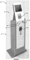
- FIG. 1 discloses an exemplary modular ATM 10 according to one or more implementations of the present disclosure.
- the modular ATM 10 includes a head portion 12 and a base portion 14.
- the head portion 12 and the base portion 14 can collectively define a housing for components and subsystems of the exemplary modular ATM 10.
- the exemplary head portion 12 and the exemplary base portion 14 house internal components and subsystems.
- the exemplary base portion 14 is configured to receive power from the grid and direct power to the head portion 12, as set forth in greater detail below.
- the internal components and subsystems of the exemplary head portion 12 and the exemplary base portion 14 are set forth in greater detail below.
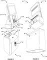
- the exemplary base portion 14 defines a shelf 16 sized to receive a bottom of the exemplary head portion 12.
- the exemplary head portion 12 rests on the shelf 16.
- Posts, such as post 18, project away from the shelf 16.
- Each of the exemplary posts 18 is in a slot, such as slot 20, defined in the bottom of the exemplary head portion 12.
- the exemplary posts 18 can be shaped to include a relatively wider head and relatively narrow body.
- the exemplary slots 20 can be keyed such that a first portion of the slot is relatively wider to receive the head of one of the posts 18 and a second portion of the slot is relatively narrow, sized similarly to the relatively narrow body of the post 18.
- the head portion 12 is lowered onto the shelf 16 so that each of the heads of the posts 18 is received in the relatively wider portion of one of the slots 20. Then, the head portion 12 is moved deeper into the shelf 16, towards a back wall 22 of the shelf 16, whereby the heads of the posts 18 are captured by the narrow portions of the slots 20, precluding the head portion 12 from being lifted relative to the base portion 14.
- Mating plugs/sockets are mounted in the shelf 16 and in the back of the head portion 12.
- the exemplary head portion 12 includes a first half 24 of a socket pair.
- the exemplary socket-half 24 is mounted to the head portion 12 and is exposed on an outside surface of the head portion 12.
- the exemplary socket-half 24 is selectively connectable to the user-interface devices and to the computing device 34 and to the battery 76, to direct electric power when connected to the user-interface devices and to the computing device 34 and to the battery 76.
- a second half 26 of the socket pair is mounted in the back wall 22 of the shelf 16 of the base portion 14.
- the first half 24 and the second half 26 mate when the head portion 12 is moved deeper into the shelf 16, against the back wall 22.
- the socket pair can define a plurality of distinct connections when mated together.
- data and power signals can be communicated through the socket pair 24, 26, between the internal components and subsystems of the exemplary head portion 12 and the exemplary base portion 14.
- the exemplary head portion 12 and the exemplary base portion 14 also include structures to enhance security of interconnection.
- the exemplary head portion 12 includes one or more blades, such as blade 28.
- the exemplary base portion 14 can include a slot, such as slot 30, to receive each blade.
- the exemplary base portion 14 further includes a lock at each slot, such as lock 32.
- the exemplary lock 32 can receive a key to convert from an unlocked configuration to a locked configuration, and from the locked configuration to the unlocked configuration.
- the blade 28 is received in the slot 30 when the head portion 12 is moved deeper into the shelf 16, against the back wall 22. After the blade 28 is received in the slot 30, the lock 32 can be engaged to lock the blade 28 in the slot 30.
- Figure 4 discloses a functional block diagram of the exemplary modular ATM 10 according to one or more implementations of the present disclosure.
- the modular ATM 10 includes different structures and subsystems for receiving input from a user and executing transactions.
- a dashed line is shown in Figure 4 to delineate the components of the head portion 12 in the exemplary embodiment and the components of the base portion 14.
- the modular ATM 10 includes a computing device 34.
- the exemplary computing device 34 has one or more processors and a non-transitory, computer readable medium.
- the computing device 34 operates under the control of an operating system, kernel and/or firmware and executes or otherwise relies upon various computer software applications, components, programs, objects, modules, data structures, etc.
- the computer readable medium (memory) of the computing device 34 can include random access memory (RAM) devices comprising the main storage of computing device 34, as well as any supplemental levels of memory, e.g., cache memories, nonvolatile or backup memories (e.g., programmable or flash memories), read-only memories, etc.
- RAM random access memory
- the memory may be considered to include memory storage physically located elsewhere in computing device 34, such as any cache memory in a processor, as well as any storage capacity used as a virtual memory.
- the computing device 34 can also include one or more mass storage devices, e.g., a floppy or other removable disk drive, a hard disk drive, a direct access storage device (DASD), an optical drive (e.g., a CD drive, a DVD drive, etc.), and/or a tape drive, among others, represented by memory 36.
- mass storage devices e.g., a floppy or other removable disk drive, a hard disk drive, a direct access storage device (DASD), an optical drive (e.g., a CD drive, a DVD drive, etc.), and/or a tape drive, among others, represented by memory 36.
- mass storage devices e.g., a floppy or other removable disk drive, a hard disk drive, a direct access storage device (DASD), an optical drive (e.g., a CD drive
- the exemplary modular ATM 10 also includes a display 38.
- the computing device 34 can control the display 38 to present information to the user for furthering completion of the transaction.
- the display 38 can be a touch screen that allows the user to enter information through the display 38.
- the exemplary display 38 is configured to transmit any user-entered information to the computing device 34.
- the exemplary modular ATM 10 also includes a key pad 40 and an encryption module 44.
- the exemplary key pad 40 includes a plurality of keys, such as key 42.
- the exemplary encryption module 44 has one or more processors and a non-transitory, computer readable medium. The user can press the keys of the key pad 40 to enter a pin.
- the key pad 40 is placed in communication with the encryption module 44 and therefore the numbers of the pin are received by the encryption module 44. It is noted that the communication of the pin is direct and secure; the pin cannot be intercepted between the key pad 40 and the encryption module 44.
- the pin is then encrypted by the encryption module 44 to define a pin block.
- the encryption module 44 includes a network encryption key and applies the network encryption key to encrypt the pin to the pin block.
- the exemplary encryption module 44 is configured to transmit the pin block to the computing device 34, which can direct the pin block away from the modular ATM 10 during completion of a financial transaction.
- the exemplary modular ATM 10 also includes a card reader 46.
- the card reader 46 can receive a token from the user, such as a card.
- the card reader 46 can read data on a magnetic strip on the back of a card and/or can read data from a chip embedded in the card.
- the card reader 46 can be configured to execute read and write operations with respect to any storage medium fixed to the user's card.
- the exemplary card reader 46 is configured to transmit any data read from the user's card to the computing device 34, which can direct the data read from the card away from the modular ATM 10 during completion of a financial transaction.
- the exemplary card reader 46 can also be configured to receive commands and data from the computing device 34 and change data stored on the user's card.
- the exemplary modular ATM 10 also includes a printer module 48.
- the computing device 34 can control the printer module 48 to print a receipt when a transaction has been completed.
- the printer module 48 can communicate one or more messages to the computing device 34, such as a maintenance message regarding the need to refill printer paper.
- the exemplary modular ATM 10 also includes an article exchange unit 50.
- the article exchange unit 50 is configured to receive items such as checks.
- An exemplary article exchange unit 50 can include a drum on which received items are stored.
- the article exchange unit 50 can be a recycler.
- the exemplary article exchange unit 50 includes a slot 52 defined on an exterior of the modular ATM 10 for the passage of such items.
- an article exchange unit can be configured to facilitate the receive other items.
- the article exchange unit 50 can include one or more sensors and transmit signals from any such sensors to the computing device 34 to execute an exchange.
- the computing device 34 can control the article exchange unit 50 in response to such signals.
- the article exchange unit 50 can include a sensor that detects receipt of an item such as a check.
- the article exchange unit 50 can include a further sensor in the form of a scanner that generates an image of the received item and transmits the image to the computing device 34.
- the computing device 34 can control the article exchange unit 50 to dispense the item(s) requested by the user.
- the exemplary modular ATM 10 also includes a printer module 54.
- the printer module 54 can generate a continuous record of all transactions executed by the modular ATM 10.
- the computing device 34 can control the printer module 54 to supplement the record after each transaction has been completed.
- the printer module 54 can communicate one or more messages to the computing device 34, such as a maintenance message regarding the need to refill printer paper.
- the exemplary modular ATM 10 also includes an access module 56.
- the access module 56 can be positioned proximate to a rear side of the modular ATM 10.
- the access module 56 can be utilized for service and support technicians.
- the access module 56 can be utilized by a field engineer to complete software updates to the computing device 34.
- the access module 56 can also be utilized when non-software updates and maintenance is performed, such as the refilling of printer paper or currency.
- the exemplary modular ATM 10 also includes a transceiver 58.
- the exemplary transceiver 58 is configured to facilitate communication between the computing device 34 and other computing devices that are distinct from and physically remote from the computing device 34.
- An example of such a remote computing device is a server computing device, such as a banking or financial institution server communicating with a plurality of ATMs.
- the exemplary transceiver 58 places the computing device 34 in communication with one or more networks, such as network 60.
- the network 60 can be a local area network (LAN), a wide area network (WAN) such as the Internet, a Multi-protocol label switching (MPLS) network, a cellular network such as operated by cellular phone companies, or any combination thereof.
- the transceiver 58 can transmit data and requests for input generated by the computing device 34 and receive responses to these requests, directing these responses to the computing device 34.
- the exemplary modular ATM 10 also includes a transceiver 62.
- the exemplary transceiver 62 is configured to facilitate communication between at least one of the encryption module 44 and the computing device 34 and other computing devices that are distinct from and physically proximate to the modular ATM 10.
- An example of such a proximate computing device is a smartphone possessed by the user.
- the dashed connection lines in Figure 1 represent optional interconnections.
- the exemplary transceiver 62 can place the user's smartphone in communication with the encryption module 44, the computing device 34, or both.
- the exemplary transceiver 62 can implement various communication protocols.
- the transceiver 62 can be a Near Field Communication (NFC) device.
- the transceiver 62 can be a Bluetooth beacon.
- the transceiver 62 can transmit and receive data and requests for input generated by the encryption module 44 and/or the computing device 34, such transmissions occurring with the user's smart phone for example.
- NFC Near Field Communication
- the exemplary modular ATM 10 also includes an advanced function dispenser (AFD) 64.
- the AFD 64 can dispense banknotes, such as currency.
- the exemplary AFD 64 is positioned in a safe 66.
- One or more cassettes or cash boxes 68 are also positioned and protected in the safe 66.
- Banknotes are stored in the cassettes 68 for disbursement to a user of the modular ATM 10.
- the exemplary AFD 64 can extract the banknotes from one or more of the cassettes 68 and direct them out of the modular ATM 10 through the slot 52.
- the AFD 64 thus communicates with the slot 52 in parallel with the article exchange unit 50.
- the exemplary AFD 64 can communicate with and be controlled by the computing device 34 (this is not illustrated in Figure 4 due to the number of components already shown).
- the exemplary AFD 64 communicates with the computing device 34 through the socket-half 24 and the second socket-half 26.
- Each of the cassettes 68 can engage the AFD 64 through a rack whereby the positioning of the cassettes 68 is controlled.
- the each of the cassettes 68 and the AFD 64 can include mating mechanical connectors of any form, whereby a positive mechanical interconnection is confirmed electronically.
- a signal or lack thereof can be communicated to the computing device 34 whereby an error message is generated, or the modular ATM 10 can be disabled.
- the exemplary modular ATM 10 also includes a scanner 70.
- the scanner 70 can scan, for example, at least a portion of a display of a smart phone and communicate the scanned display to the computing device 34.
- a token can be displayed on the display of the smart phone and thus scanned by the scanner 70.
- the token can be a bar code, a quick response (QR) code, a number, a string of alphanumeric characters, a weblink, or some other symbolic indicia.
- QR quick response
- the exemplary scanner 70 is configured to transmit any scanned data to the computing device 34, which can direct the scanned away from the modular ATM 10 during completion of a financial transaction.
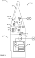
- FIG. 5 is a second functional block diagram of the exemplary modular ATM 10.
- Figure 5 is provided to illustrate a power management arrangement of the exemplary modular ATM 10.
- the base portion 14 can receive power from the grid 72.
- the base portion 14 can include a power management module 74.
- the power management module 74 can direct power from the grid 72 to the subsystems and components within the base portion 14.
- the AFD 64 is one example of a component of the base portion 14.
- the power management module 74 can also convert power received from the grid 72 as desired for the head portion 12.
- the power management module 74 can convert power from AC to DC and can direct DC power to the head portion 12 through the socket-half 24 and second socket-half 26.
- the power management module 74 delivers 12 VDC to the head portion through the socket pair 24, 26.
- a battery 76 is provided in the exemplary head portion 12 to power the subsystems and components within the head portion 12 when power is not supplied from the base portion 14, such as during transport.
- the battery 76 can provide 12 VDC. In one or more embodiments of the present disclosure, the battery 76 can provide ten minutes of power to the subsystems and components within the head portion 12.
- the battery 76 can provide electrical power to a 12 VDC rail, referenced at 78, when power is not supplied from the base portion 14.
- One or more of the user-interface devices receives power off of the first rail 78.
- the socket-half 24 is directly connected to the first rail 78 so that power can be supplied to the rail from the base portion 14 when the head portion 12 and base portion 14 are interconnected.
- the 12 VDC power from the base portion 14 is directed to the rail 78, to a battery charger circuit 80, and to a relay 82.
- the battery charger circuit 80 is also connected to the relay 82, as shown in Figure 5 .
- the exemplary battery charger circuit 80 is disposed between the relay 82 and the socket-half 24.
- the relay 82 is disposed between the battery 76 and the first rail 78.
- the relay 82 is arranged such that the relay 82 connects the battery 76 and the first rail 78 in a first configuration and in a second configuration selectively switches the battery 76 off of the first rail 78.
- the relay 82 is switched from the first configuration to the second configuration when electrical power is available at the socket-half 24.
- the battery charger circuit 80 is connected to the battery 76 when the relay 82 is in the second configuration.
- the battery 76 delivers power to the 12 VDC rail 78 if power is not supplied from the base portion 14.
- the relay 82 is switched, connecting the battery 76 and the battery charger circuit 80 and isolating the battery 76 from the rail 78, so that the battery 76 can be charged.
- the battery 76 allows the various devices, subsystems, and components within the head portion 12 to be changed without the loss of power to the other devices, subsystems, and components.
- the battery 76 is thus selectively connectable to the user-interface devices and to the computing device 34.
- An appropriately-sized capacitor is positioned on the rail 78 so that power is maintained on the rail 78 during the switch of power source between the battery 76 and the base portion 14.
- An exemplary capacitor is referenced in Figure 6 at 96.
- the exemplary capacitor 96 is connected to the user-interface devices and to the computing device 34 and to the battery 76, through the rail 78.
- the capacitor 96 is loaded by the battery 76 initially and directs electric power to the user-interface devices and to the computing device 34 when power from the battery 76 is lost, particularly when the relay 82 is being switch between the first configuration and the second configuration.
- An exemplary circuit assembly 84 is connected to the rail 78, converts the first level of voltage on the first rail 78 to a second level of voltage different from the first level of voltage, and communicates and outputs 5 VDC to a rail 86.
- the exemplary circuit assembly 84 is shown in Figure 10 .
- An exemplary circuit assembly 88 is connected to the rail 78, converts the first level of voltage on the first rail 78 to a third level of voltage different from the first level of voltage, and communicates and outputs 19 VDC to a rail 90.
- the exemplary circuit assembly 88 is shown in Figure 9 .
- An exemplary circuit assembly 92 is connected to the rail 78, converts the first level of voltage on the first rail 78 to a fourth level of voltage different from the first level of voltage, and communicates and outputs 24 VDC to a rail 94.
- the exemplary circuit assembly 92 is shown in Figures 8A and 8B .
- embodiments of the present disclosure may include less than four rails or more than four rails, may include rails at different voltage levels, and/or may include multiple rails of the same voltage level if desired.
- three 24 VDC rails are established. Two of the 24 VDC rails are used to power peripherals/modules/devices and one 24 VDC rail is used to power the battery charging circuitry. The charger rail is not enabled unless the 12 VDC rail 78 is powered from the base portion 14. The reason for multiple 24 VDC rails to power peripherals/modules/devices in the exemplary embodiment is that only so much power can be directed through the DC-DC converter logic.
- Figure 6 is a first circuit schematic of a first portion of an electrical system of the exemplary modular ATM 10. It is noted that any particular value of components shown in the Figures or particular part numbers of components shown in the Figures are exemplary; the present disclosure is not limited to such values and such part numbers.
- the exemplary first portion shows the power input portion of the head portion 12.
- Figures 7A - 7C are portions of a second circuit schematic of a second portion of the electrical system of the exemplary modular ATM 10.
- the exemplary second portion is a battery charging circuit.
- Figures 8A and 8B are portions of a third circuit schematic of a third portion of the electrical system of the exemplary modular ATM 10.
- the exemplary third portion is the circuit assembly 92, for outputting 24 VDC to the rail 94.
- Figure 9 is a fourth circuit schematic of a fourth portion of the electrical system of the exemplary modular ATM 10.
- the exemplary fourth portion is the circuit assembly 88, for outputting 19 VDC to a rail 90. It is noted that "EN" shown in Figure 9 is further explained in Figure 8B .
- Figure 10 is a fifth circuit schematic of a fifth portion of the electrical system of the exemplary modular ATM 10.
- the exemplary fourth portion is the circuit assembly 84, for outputting 5 VDC to a rail 86.
- the user-interface devices of the exemplary modular ATM 10 are configured to receive an input from a user.
- the exemplary modular ATM 10 includes a plurality of user-interface devices which can be used individually by the user or in groups of two or more.
- the exemplary modular ATM 10 includes the key pad 40, the display 38, the scanner 70, the NFC transceiver 62, and the card reader 46.
- the user may use only the NFC transceiver 62 when directing the input to the exemplary modular ATM 10.
- the input can be data received from more than one user-interface device.
- the user may use the key pad 40, display 38, and the card reader 46 when providing the input to the exemplary modular ATM 10.
- the input corresponds at least in part to an account maintained by a financial institution.
- the input can be a scan of a QR code that was generated by a financial institution and transmitted to a smartphone of a user.
- the user can present the QR code in front of the scanner 70 to provide the input.
- the QR code can correspond to the user's account with the financial institution and an amount to be dispensed (as part of a pre-staged transaction).
- the input can be the data contained in a chip in a card, which includes the user's account number.
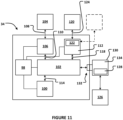
- Figure 11 is a schematic of a control architecture of the exemplary modular ATM 10.
- the exemplary modular ATM 10 applies a publish/subscribe protocol in controlling at least some of its functions and operations.
- the computing device 34 can be one or more processors.
- Reference number 98 is utilized to reference processing operations for the overall functionality of the exemplary modular ATM 10.
- Processor 98 can be part of the computing device 34 or can be running on the computing device 34, and can itself run a terminal service.
- a service such as the terminal service, can be provided through hardware, software, or a combination of hardware and software.
- a service can receive data from a component or device or peripheral or subsystem of the exemplary modular ATM 10.
- a service can also generate a message containing the received data, wherein the data can be received in one format and the message is in another format.
- Any particular component or device or peripheral or subsystem of the exemplary modular ATM 10 can communicate data to a corresponding service and the service can communicate a message containing the data in JSON format and according to the MQTT protocol.
- the service can define a topic of the message and the topic of the message is contained within the message.
- a topic can itself be defined by one or more topic levels.
- the service can direct the message, defined by one or more topic levels, to a broker 102.
- the broker can publish the message to other service(s) that have subscribed to the topic of the message.
- a service can also subscribe to messages defined by particular topics.
- the exemplary terminal service 100 is running on the processor 98 and can be configured to subscribe to messages defined by particular topics. Topics can be defined in part by the device from which a message originates (as will be described in greater detail below).
- the broker 102 receives all messages and publishes the messages to services that have subscribed to the topic associated with each message. Thus, the services do not directly communicate with one another.
- the broker 102 can be the Eclipse Mosquitto TM broker (see https://mosquitto.org/).
- the terminal service 100 can be subscribed to all topics and will therefore receive all messages published by the broker 102, other than messages emanating from the terminal service 100 itself. Messages received by the terminal service 100 can be directed to the processor 98 for processing according to logic stored in memory 36.
- the exemplary broker 102 is a secondary service running on the processor 98 of the computing device 34.
- the term "secondary" is applied to distinguish the broker 102 from other services based on generally functionality and not on importance. For example, unlike a service that may receive data in a first format or protocol and transmit the data in a different format or protocol, the broker 102 receives and transmits messages in the same format or protocol. Further, the broker 102 filters messages and publishes messages to the appropriate services.
- a user can insert a bank card into a card reader, such as card reader 46.
- a card reader such as card reader 46.
- reference number 104 is utilized as a generic user-interface device.
- box 104 corresponds to the card reader 46.
- the user-interface device 104 in the form of the card reader 46 is configured to transmit the input (card data) to the broker 102.
- the exemplary processor 98 is also running a user-interface service, referenced at 106.
- the input (card data) is first transmitted by the user-interface 104 to the user-interface service 106.
- Communication between the user-interface device 104 and the user-interface service 106 is referenced at 108.
- the input (card data) can be first transmitted to the user-interface service 106.
- the user-interface service 106 can convert the input (card data) to a different format.
- the user-interface service 106 can convert the input (card data) to JSON format in MQTT protocol.
- the user-interface service 106 can then transmit the input (card data), in JSON format and in MQTT protocol, to the broker 102.
- Communication between the user-interface service 106 and the broker 102 is referenced at 110.
- the communication from the user-interface service 106 can designate a topic (with one or more topic levels) for the message to be published by the broker 102.
- the broker 102 is configured to publish the received data input as a first message.
- the first message will be in JSON format and in MQTT protocol.
- One or more other services may be subscribed to the topic of the data input and thus receive the first message.
- the terminal service 100 has subscribed, with the broker 102, to the topic associated with the data contained in the communication from the user-interface service 106. Communication between the terminal service 100 and the broker 102 is referenced at 114.
- the terminal service 100 and the user-interface service 106 are isolated from one another with respect to direct communications; the exemplary terminal service 100 and the exemplary user-interface service 106 do not communicate directly with one another.
- the terminal service 100 is configured to receive the first message from the broker 102 and transmit the content of the first message to the processor 98. Communication between the terminal service 100 and the processor 98 is referenced at 116.
- the terminal service 100 is configured to transmit the content of the first message to the processor 98 for processing according to logic stored in memory 36.
- processor 98 can determine one or more commands to transmit in response to receipt of the content of the first message.
- the processor 98 may transmit the data contained in the first message outside of the modular ATM 10 for validation/approval.
- the processor 98 may issue a command to the display 38 to display a message for the user to enter a PIN.
- the terminal service 100 is configured to convert the format of the first message from JSON format and MQTT protocol to another format/protocol before transmitting to the processor 98, if necessary.
- the processor 98 can determine that banknotes should be dispensed to the user.
- reference number 120 is utilized as a generic output device.
- box 120 corresponds to the AFD 64.
- the exemplary processor 98 can direct an appropriate command to the terminal service 100.
- the terminal service 100 can convert the command to a different format if necessary.
- the terminal service 100 can convert the command to JSON format in MQTT protocol.
- the terminal service 100 can then transmit the command, in JSON format in MQTT protocol, to the broker 102.
- the communication from the terminal service 100 can designate a topic (with one or more topic levels) for the message to be published by the broker 102.
- the broker 102 can publish a second message containing the command.
- the topic of the second message can include, as a topic level, "AFD" for example.
- the exemplary processor 98 of the computing device 34 is also running an AFD service, referenced at 112.
- the AFD service 112 can be subscribed to messages that contain commands for the AFD 64 and thus receive the second message, in JSON format and MQTT protocol, from the broker 102. Communication between the AFD service 112 and the broker 102 is referenced at 118.
- the AFD service 112 can convert the command to a different format if desired.
- the AFD service 112 can convert the command from the JSON format and/or MQTT protocol.
- the AFD service 112 can then transmit the command to the output device 120 (the AFD 64 in this example) for execution of the command.
- the exemplary AFD service 11 is illustrated with a bus-based messaging protocol, referenced at 122.
- output devices and/or user-interface devices can be configured to receive and transmit communications under a common protocol that may be different from the protocol of the services and the broker 102.
- Lightweight Application Communication Bus (LACB) and Extensions for Financial Services (XFS) Service Provider are two examples of such protocols.
- a service may include a bus applying these protocols so that a single service can communicate with more than one device.
- Figure 11 shows AFD service 112 configured to communicate with a second device (in phantom) other than the box 120 using the bus-based messaging protocol 122.
- the AFD service 112 can communicate the command to output device 120 (the AFD 64 in this example). Communication between the AFD service 112 and the output device 120 is referenced at 124.
- the AFD 64 dispenses banknotes in response to the second message.
- the communication architecture disclosed above allows subcomponents of the exemplary modular ATM 10 to be replaced with greater ease.
- all of the components of the modular ATM 10 can apply the architecture.
- the user-interface device 104 could be the scanner 70 and the processor 98 could be running a scanner service.
- the display 38 could be a user-interface device 104 or an output device 120 and the processor 98 could be running a display service.
- the user-interface device 104 could be the encrypting key pad 40 and messages containing the encrypted PIN can be transmitted in JSON format and in MQTT protocol.
- the initial sequence began based on an input from a user.
- the communication architecture can also be applied for diagnostic data.
- the various devices of the modular ATM 10 can include diagnostic sensors to alert the computing device 34 of problems and/or confirm operating status.
- the exemplary AFD 64 is configured to transmit diagnostic data to the broker 102 through the AFD service 112 and the broker 102 is configured to transmit messages to the terminal service 100 containing the diagnostic data.
- one or more of the devices can respond to the receipt of a message by publishing a message.
- the AFD 64 can confirm that banknotes have been dispensed by publishing a message that will be received by the processor 98.
- one or more of the services associated with a particular device can subscribe to messages published by a service other than the terminal service 100.
- the AFD 64 can subscribe to messages published by the encrypting key pad 40.
- the AFD 64 can first confirm receipt of a message published previously by the encrypting key pad 40, before executing a command to dispense bank notes. This feature can inhibit the perpetration of fraudulent activity, such as j ackpotting.
- FIG 11 shows another feature of one or more implementations of the present disclosure.
- a peripheral 126 is mounted in the housing defined by the head portion 12 and the base portion 14. The peripheral 126 can be configured to perform an action and is in communication with the broker 102.
- the peripheral 126 can be the article exchange unit 50. Further, the article exchange unit 50 can be a recycler that operates through an XFS Service Provider, referenced at 128.
- a microprocessor chip 130 can be interconnected with the computing device 34 through a physical socket pair 132.
- the exemplary microprocessor chip 130 is interconnected with the peripheral 126 and is running a peripheral service 134 configured to bridge communications between the XFS Service Provider 128 and the broker 102.
- the peripheral service 134 running on the microprocessor chip 130 is configured to convert messages received from the broker 102 to XFS format so that modification of the programming of the peripheral 126 is not required for the peripheral to be utilized in the modular ATM 10.
- each device can be operating its respective service on its own processor.
- the recycler is shown operating on its own compute platform (the microprocessor chip 130). But embodiments of the present disclosure can be practiced wherein each device (AFD 64, NFC transceiver 62, card reader 46, encrypting key pad 40, etc.) is on a separate compute platform and communicating with a broker 102 over network connections.
- the computing device 34 is configured to transmit content of a message received from the broker 102 outside of the exemplary modular ATM 10.
- the terminal service 100 can convert a format of the second message from a first protocol to a second protocol prior in order for the processor 98 to transmit the content of the second message outside of the exemplary modular ATM 10 if necessary.
Landscapes
- Business, Economics & Management (AREA)
- Physics & Mathematics (AREA)
- General Physics & Mathematics (AREA)
- Accounting & Taxation (AREA)
- Finance (AREA)
- Engineering & Computer Science (AREA)
- Theoretical Computer Science (AREA)
- Strategic Management (AREA)
- General Business, Economics & Management (AREA)
- Toxicology (AREA)
- Health & Medical Sciences (AREA)
- Computer Networks & Wireless Communication (AREA)
- Computer Vision & Pattern Recognition (AREA)
- Computer Security & Cryptography (AREA)
- Development Economics (AREA)
- Economics (AREA)
- Electromagnetism (AREA)
- General Health & Medical Sciences (AREA)
- Artificial Intelligence (AREA)
- Power Engineering (AREA)
- Financial Or Insurance-Related Operations Such As Payment And Settlement (AREA)
- Management, Administration, Business Operations System, And Electronic Commerce (AREA)
- Lock And Its Accessories (AREA)
- Coin-Freed Apparatuses For Hiring Articles (AREA)
- Data Exchanges In Wide-Area Networks (AREA)
- Control Of Vending Devices And Auxiliary Devices For Vending Devices (AREA)
Description
- This application claims the benefit of
United States Provisional Patent Application Serial No. 62/576,055 for a MODULAR ATM, filed on 10/23/2017 - The present disclosure relates to automated transaction machines (ATMs).
- Banking transactions requested by a customer may be processed in different ways. For example, a banking customer may visit a teller and the teller may process the banking transaction. Alternatively, the customer may use an ATM to process a banking transaction.
- The background description provided herein is for the purpose of generally presenting the context of the disclosure. Work of the presently named inventors, to the extent it is described in this background section, as well as aspects of the description that may not otherwise qualify as prior art at the time of filing, are neither expressly nor impliedly admitted as prior art against the present disclosure. Documents
US2012/145782 A1 ,US2002/000913 A1 ,EP1926058 A2 andWO2007/036915 A1 as well as https:// web.archive.org/web/20161115030956/https://lamassu.is/product/santo-tirso/ disclose examples of an ATM. - The ATM of the present invention is as set out in the appended claims.
- The detailed description set forth below references the following drawings:
-
Figure 1 is a perspective view of a modular ATM according to an exemplary embodiment of the present disclosure; -
Figure 2 is a first partially-exploded view of the modular ATM according to the exemplary embodiment of the present disclosure; -
Figure 3 is a second partially-exploded view of the modular ATM according to the exemplary embodiment of the present disclosure; -
Figure 4 is a first functional block diagram of the exemplary modular ATM; -
Figure 5 is a second functional block diagram of the exemplary modular ATM; -
Figure 6 is a first circuit schematic of a first portion of an electrical system of the exemplary modular ATM; -
Figures 7A - 7C are portions of a second circuit schematic of a second portion of the electrical system of the exemplary modular ATM, the second portion being a battery charging circuit; -
Figures 8A and 8B are a third circuit schematic of a third portion of the electrical system of the exemplary modular ATM; -
Figure 9 is a fourth circuit schematic of a fourth portion of the electrical system of the exemplary modular ATM; -
Figure 10 is a fifth circuit schematic of a fifth portion of the electrical system of the exemplary modular ATM; and -
Figure 11 is a schematic of a control architecture of the exemplary modular ATM. - The present disclosure, as demonstrated by the exemplary embodiment described below, can provide an ATM that is modular in a plurality of different ways. For example, the exemplary modular ATM includes a power management system that allows peripherals of the ATM to be replaced without powering down other peripherals. Also, a plurality of peripherals can be grouped together in a head portion with a battery, so that these peripherals can be powered by the battery during periods away from the grid. Further, the exemplary modular ATM applies a publish/subscribe communication architecture that allows peripherals to be changed with the need to recompile or alter programing of other components of the ATM.
- Referring now to the drawings,
Figure 1 discloses an exemplarymodular ATM 10 according to one or more implementations of the present disclosure. Themodular ATM 10 includes ahead portion 12 and abase portion 14. Thehead portion 12 and thebase portion 14 can collectively define a housing for components and subsystems of the exemplarymodular ATM 10. Theexemplary head portion 12 and theexemplary base portion 14 house internal components and subsystems. Theexemplary base portion 14 is configured to receive power from the grid and direct power to thehead portion 12, as set forth in greater detail below. The internal components and subsystems of theexemplary head portion 12 and theexemplary base portion 14 are set forth in greater detail below. - As best shown in
Figures 2 and 3 , theexemplary base portion 14 defines ashelf 16 sized to receive a bottom of theexemplary head portion 12. Theexemplary head portion 12 rests on theshelf 16. Posts, such aspost 18, project away from theshelf 16. Each of theexemplary posts 18 is in a slot, such asslot 20, defined in the bottom of theexemplary head portion 12. Theexemplary posts 18 can be shaped to include a relatively wider head and relatively narrow body. Theexemplary slots 20 can be keyed such that a first portion of the slot is relatively wider to receive the head of one of theposts 18 and a second portion of the slot is relatively narrow, sized similarly to the relatively narrow body of thepost 18. In operation, thehead portion 12 is lowered onto theshelf 16 so that each of the heads of theposts 18 is received in the relatively wider portion of one of theslots 20. Then, thehead portion 12 is moved deeper into theshelf 16, towards aback wall 22 of theshelf 16, whereby the heads of theposts 18 are captured by the narrow portions of theslots 20, precluding thehead portion 12 from being lifted relative to thebase portion 14. - Mating plugs/sockets (socket-halves forming a socket pair) are mounted in the
shelf 16 and in the back of thehead portion 12. Theexemplary head portion 12 includes afirst half 24 of a socket pair. The exemplary socket-half 24 is mounted to thehead portion 12 and is exposed on an outside surface of thehead portion 12. The exemplary socket-half 24 is selectively connectable to the user-interface devices and to thecomputing device 34 and to thebattery 76, to direct electric power when connected to the user-interface devices and to thecomputing device 34 and to thebattery 76. Asecond half 26 of the socket pair is mounted in theback wall 22 of theshelf 16 of thebase portion 14. In the exemplary embodiment, thefirst half 24 and thesecond half 26 mate when thehead portion 12 is moved deeper into theshelf 16, against theback wall 22. The socket pair can define a plurality of distinct connections when mated together. In operation, data and power signals can be communicated through thesocket pair exemplary head portion 12 and theexemplary base portion 14. - The
exemplary head portion 12 and theexemplary base portion 14 also include structures to enhance security of interconnection. Theexemplary head portion 12 includes one or more blades, such asblade 28. Theexemplary base portion 14 can include a slot, such asslot 30, to receive each blade. Theexemplary base portion 14 further includes a lock at each slot, such aslock 32. Theexemplary lock 32 can receive a key to convert from an unlocked configuration to a locked configuration, and from the locked configuration to the unlocked configuration. In the exemplary embodiment, theblade 28 is received in theslot 30 when thehead portion 12 is moved deeper into theshelf 16, against theback wall 22. After theblade 28 is received in theslot 30, thelock 32 can be engaged to lock theblade 28 in theslot 30. -
Figure 4 discloses a functional block diagram of the exemplarymodular ATM 10 according to one or more implementations of the present disclosure. Themodular ATM 10 includes different structures and subsystems for receiving input from a user and executing transactions. A dashed line is shown inFigure 4 to delineate the components of thehead portion 12 in the exemplary embodiment and the components of thebase portion 14. - The
modular ATM 10 includes acomputing device 34. Theexemplary computing device 34 has one or more processors and a non-transitory, computer readable medium. Thecomputing device 34 operates under the control of an operating system, kernel and/or firmware and executes or otherwise relies upon various computer software applications, components, programs, objects, modules, data structures, etc. The computer readable medium (memory) of thecomputing device 34 can include random access memory (RAM) devices comprising the main storage ofcomputing device 34, as well as any supplemental levels of memory, e.g., cache memories, nonvolatile or backup memories (e.g., programmable or flash memories), read-only memories, etc. In addition, the memory may be considered to include memory storage physically located elsewhere incomputing device 34, such as any cache memory in a processor, as well as any storage capacity used as a virtual memory. Thecomputing device 34 can also include one or more mass storage devices, e.g., a floppy or other removable disk drive, a hard disk drive, a direct access storage device (DASD), an optical drive (e.g., a CD drive, a DVD drive, etc.), and/or a tape drive, among others, represented bymemory 36. - The exemplary
modular ATM 10 also includes adisplay 38. Thecomputing device 34 can control thedisplay 38 to present information to the user for furthering completion of the transaction. Thedisplay 38 can be a touch screen that allows the user to enter information through thedisplay 38. Theexemplary display 38 is configured to transmit any user-entered information to thecomputing device 34. - The exemplary
modular ATM 10 also includes akey pad 40 and anencryption module 44. Generally, the combination of a key pad and an encryption module are referred to in the art as an encrypted pin pad (EPP). The exemplarykey pad 40 includes a plurality of keys, such askey 42. Theexemplary encryption module 44 has one or more processors and a non-transitory, computer readable medium. The user can press the keys of thekey pad 40 to enter a pin. Thekey pad 40 is placed in communication with theencryption module 44 and therefore the numbers of the pin are received by theencryption module 44. It is noted that the communication of the pin is direct and secure; the pin cannot be intercepted between thekey pad 40 and theencryption module 44. The pin is then encrypted by theencryption module 44 to define a pin block. Theencryption module 44 includes a network encryption key and applies the network encryption key to encrypt the pin to the pin block. Theexemplary encryption module 44 is configured to transmit the pin block to thecomputing device 34, which can direct the pin block away from themodular ATM 10 during completion of a financial transaction. - The exemplary
modular ATM 10 also includes acard reader 46. Thecard reader 46 can receive a token from the user, such as a card. Thecard reader 46 can read data on a magnetic strip on the back of a card and/or can read data from a chip embedded in the card. Thecard reader 46 can be configured to execute read and write operations with respect to any storage medium fixed to the user's card. Theexemplary card reader 46 is configured to transmit any data read from the user's card to thecomputing device 34, which can direct the data read from the card away from themodular ATM 10 during completion of a financial transaction. Theexemplary card reader 46 can also be configured to receive commands and data from thecomputing device 34 and change data stored on the user's card. - The exemplary
modular ATM 10 also includes aprinter module 48. Thecomputing device 34 can control theprinter module 48 to print a receipt when a transaction has been completed. Theprinter module 48 can communicate one or more messages to thecomputing device 34, such as a maintenance message regarding the need to refill printer paper. - The exemplary
modular ATM 10 also includes anarticle exchange unit 50. In the exemplary embodiment, thearticle exchange unit 50 is configured to receive items such as checks. An exemplaryarticle exchange unit 50 can include a drum on which received items are stored. Thearticle exchange unit 50 can be a recycler. The exemplaryarticle exchange unit 50 includes aslot 52 defined on an exterior of themodular ATM 10 for the passage of such items. In other embodiments of the present disclosure, an article exchange unit can be configured to facilitate the receive other items. Thearticle exchange unit 50 can include one or more sensors and transmit signals from any such sensors to thecomputing device 34 to execute an exchange. Thecomputing device 34 can control thearticle exchange unit 50 in response to such signals. For example, thearticle exchange unit 50 can include a sensor that detects receipt of an item such as a check. Thearticle exchange unit 50 can include a further sensor in the form of a scanner that generates an image of the received item and transmits the image to thecomputing device 34. When an exchange involves the dispensation of an article to the user, thecomputing device 34 can control thearticle exchange unit 50 to dispense the item(s) requested by the user. - The exemplary
modular ATM 10 also includes aprinter module 54. Theprinter module 54 can generate a continuous record of all transactions executed by themodular ATM 10. Thecomputing device 34 can control theprinter module 54 to supplement the record after each transaction has been completed. Theprinter module 54 can communicate one or more messages to thecomputing device 34, such as a maintenance message regarding the need to refill printer paper. - The exemplary
modular ATM 10 also includes anaccess module 56. Theaccess module 56 can be positioned proximate to a rear side of themodular ATM 10. Theaccess module 56 can be utilized for service and support technicians. For example, theaccess module 56 can be utilized by a field engineer to complete software updates to thecomputing device 34. Theaccess module 56 can also be utilized when non-software updates and maintenance is performed, such as the refilling of printer paper or currency. - The exemplary
modular ATM 10 also includes atransceiver 58. Theexemplary transceiver 58 is configured to facilitate communication between thecomputing device 34 and other computing devices that are distinct from and physically remote from thecomputing device 34. An example of such a remote computing device is a server computing device, such as a banking or financial institution server communicating with a plurality of ATMs. Theexemplary transceiver 58 places thecomputing device 34 in communication with one or more networks, such asnetwork 60. Thenetwork 60 can be a local area network (LAN), a wide area network (WAN) such as the Internet, a Multi-protocol label switching (MPLS) network, a cellular network such as operated by cellular phone companies, or any combination thereof. Thetransceiver 58 can transmit data and requests for input generated by thecomputing device 34 and receive responses to these requests, directing these responses to thecomputing device 34. - The exemplary
modular ATM 10 also includes atransceiver 62. Theexemplary transceiver 62 is configured to facilitate communication between at least one of theencryption module 44 and thecomputing device 34 and other computing devices that are distinct from and physically proximate to themodular ATM 10. An example of such a proximate computing device is a smartphone possessed by the user. The dashed connection lines inFigure 1 represent optional interconnections. Theexemplary transceiver 62 can place the user's smartphone in communication with theencryption module 44, thecomputing device 34, or both. Theexemplary transceiver 62 can implement various communication protocols. For example, thetransceiver 62 can be a Near Field Communication (NFC) device. Alternatively, thetransceiver 62 can be a Bluetooth beacon. Thetransceiver 62 can transmit and receive data and requests for input generated by theencryption module 44 and/or thecomputing device 34, such transmissions occurring with the user's smart phone for example. - The exemplary
modular ATM 10 also includes an advanced function dispenser (AFD) 64. TheAFD 64 can dispense banknotes, such as currency. Theexemplary AFD 64 is positioned in a safe 66. One or more cassettes orcash boxes 68 are also positioned and protected in the safe 66. Banknotes are stored in thecassettes 68 for disbursement to a user of themodular ATM 10. Theexemplary AFD 64 can extract the banknotes from one or more of thecassettes 68 and direct them out of themodular ATM 10 through theslot 52. TheAFD 64 thus communicates with theslot 52 in parallel with thearticle exchange unit 50. Theexemplary AFD 64 can communicate with and be controlled by the computing device 34 (this is not illustrated inFigure 4 due to the number of components already shown). Theexemplary AFD 64 communicates with thecomputing device 34 through the socket-half 24 and the second socket-half 26. Each of thecassettes 68 can engage theAFD 64 through a rack whereby the positioning of thecassettes 68 is controlled. Further, the each of thecassettes 68 and theAFD 64 can include mating mechanical connectors of any form, whereby a positive mechanical interconnection is confirmed electronically. When one or more of thecassettes 68 and theAFD 64 are not properly interconnected, a signal or lack thereof can be communicated to thecomputing device 34 whereby an error message is generated, or themodular ATM 10 can be disabled. - The exemplary
modular ATM 10 also includes ascanner 70. Thescanner 70 can scan, for example, at least a portion of a display of a smart phone and communicate the scanned display to thecomputing device 34. A token can be displayed on the display of the smart phone and thus scanned by thescanner 70. The token can be a bar code, a quick response (QR) code, a number, a string of alphanumeric characters, a weblink, or some other symbolic indicia. Theexemplary scanner 70 is configured to transmit any scanned data to thecomputing device 34, which can direct the scanned away from themodular ATM 10 during completion of a financial transaction. -
Figure 5 is a second functional block diagram of the exemplarymodular ATM 10.Figure 5 is provided to illustrate a power management arrangement of the exemplarymodular ATM 10. Thebase portion 14 can receive power from thegrid 72. Thebase portion 14 can include apower management module 74. Thepower management module 74 can direct power from thegrid 72 to the subsystems and components within thebase portion 14. TheAFD 64 is one example of a component of thebase portion 14. Thepower management module 74 can also convert power received from thegrid 72 as desired for thehead portion 12. Thepower management module 74 can convert power from AC to DC and can direct DC power to thehead portion 12 through the socket-half 24 and second socket-half 26. For example, in the exemplary embodiment, thepower management module 74 delivers 12 VDC to the head portion through thesocket pair - A
battery 76 is provided in theexemplary head portion 12 to power the subsystems and components within thehead portion 12 when power is not supplied from thebase portion 14, such as during transport. Thebattery 76 can provide 12 VDC. In one or more embodiments of the present disclosure, thebattery 76 can provide ten minutes of power to the subsystems and components within thehead portion 12. Thebattery 76 can provide electrical power to a 12 VDC rail, referenced at 78, when power is not supplied from thebase portion 14. One or more of the user-interface devices receives power off of thefirst rail 78. The socket-half 24 is directly connected to thefirst rail 78 so that power can be supplied to the rail from thebase portion 14 when thehead portion 12 andbase portion 14 are interconnected. - When the
exemplary head portion 12 and theexemplary base portion 14 are interconnected, the 12 VDC power from thebase portion 14 is directed to therail 78, to abattery charger circuit 80, and to arelay 82. Thebattery charger circuit 80 is also connected to therelay 82, as shown inFigure 5 . The exemplarybattery charger circuit 80 is disposed between therelay 82 and the socket-half 24. Therelay 82 is disposed between thebattery 76 and thefirst rail 78. Therelay 82 is arranged such that therelay 82 connects thebattery 76 and thefirst rail 78 in a first configuration and in a second configuration selectively switches thebattery 76 off of thefirst rail 78. Therelay 82 is switched from the first configuration to the second configuration when electrical power is available at the socket-half 24. Thus, thebattery charger circuit 80 is connected to thebattery 76 when therelay 82 is in the second configuration. - The
battery 76 delivers power to the 12VDC rail 78 if power is not supplied from thebase portion 14. When power is supplied from thebase portion 14, therelay 82 is switched, connecting thebattery 76 and thebattery charger circuit 80 and isolating thebattery 76 from therail 78, so that thebattery 76 can be charged. Thebattery 76 allows the various devices, subsystems, and components within thehead portion 12 to be changed without the loss of power to the other devices, subsystems, and components. Thebattery 76 is thus selectively connectable to the user-interface devices and to thecomputing device 34. An appropriately-sized capacitor is positioned on therail 78 so that power is maintained on therail 78 during the switch of power source between thebattery 76 and thebase portion 14. An exemplary capacitor is referenced inFigure 6 at 96. Theexemplary capacitor 96 is connected to the user-interface devices and to thecomputing device 34 and to thebattery 76, through therail 78. Thecapacitor 96 is loaded by thebattery 76 initially and directs electric power to the user-interface devices and to thecomputing device 34 when power from thebattery 76 is lost, particularly when therelay 82 is being switch between the first configuration and the second configuration. - In the exemplary embodiment of the present disclosure, various subsystems and components within the
head portion 12 require different amounts of power. Anexemplary circuit assembly 84 is connected to therail 78, converts the first level of voltage on thefirst rail 78 to a second level of voltage different from the first level of voltage, and communicates and outputs 5 VDC to arail 86. Theexemplary circuit assembly 84 is shown inFigure 10 . Anexemplary circuit assembly 88 is connected to therail 78, converts the first level of voltage on thefirst rail 78 to a third level of voltage different from the first level of voltage, and communicates and outputs 19 VDC to arail 90. Theexemplary circuit assembly 88 is shown inFigure 9 . Anexemplary circuit assembly 92 is connected to therail 78, converts the first level of voltage on thefirst rail 78 to a fourth level of voltage different from the first level of voltage, and communicates and outputs 24 VDC to arail 94. Theexemplary circuit assembly 92 is shown inFigures 8A and 8B . - It is noted that embodiments of the present disclosure may include less than four rails or more than four rails, may include rails at different voltage levels, and/or may include multiple rails of the same voltage level if desired. In the exemplary embodiment, three 24 VDC rails are established. Two of the 24 VDC rails are used to power peripherals/modules/devices and one 24 VDC rail is used to power the battery charging circuitry. The charger rail is not enabled unless the 12
VDC rail 78 is powered from thebase portion 14. The reason for multiple 24 VDC rails to power peripherals/modules/devices in the exemplary embodiment is that only so much power can be directed through the DC-DC converter logic. -
Figure 6 is a first circuit schematic of a first portion of an electrical system of the exemplarymodular ATM 10. It is noted that any particular value of components shown in the Figures or particular part numbers of components shown in the Figures are exemplary; the present disclosure is not limited to such values and such part numbers. The exemplary first portion shows the power input portion of thehead portion 12.Figures 7A - 7C are portions of a second circuit schematic of a second portion of the electrical system of the exemplarymodular ATM 10. The exemplary second portion is a battery charging circuit.Figures 8A and 8B are portions of a third circuit schematic of a third portion of the electrical system of the exemplarymodular ATM 10. The exemplary third portion is thecircuit assembly 92, for outputting 24 VDC to therail 94.Figure 9 is a fourth circuit schematic of a fourth portion of the electrical system of the exemplarymodular ATM 10. The exemplary fourth portion is thecircuit assembly 88, for outputting 19 VDC to arail 90. It is noted that "EN" shown inFigure 9 is further explained inFigure 8B .Figure 10 is a fifth circuit schematic of a fifth portion of the electrical system of the exemplarymodular ATM 10. The exemplary fourth portion is thecircuit assembly 84, for outputting 5 VDC to arail 86. - In operation, the user-interface devices of the exemplary
modular ATM 10 are configured to receive an input from a user. The exemplarymodular ATM 10 includes a plurality of user-interface devices which can be used individually by the user or in groups of two or more. The exemplarymodular ATM 10 includes thekey pad 40, thedisplay 38, thescanner 70, theNFC transceiver 62, and thecard reader 46. For example, the user may use only theNFC transceiver 62 when directing the input to the exemplarymodular ATM 10. Alternatively, the input can be data received from more than one user-interface device. For example, the user may use thekey pad 40,display 38, and thecard reader 46 when providing the input to the exemplarymodular ATM 10. - The input corresponds at least in part to an account maintained by a financial institution. For example, the input can be a scan of a QR code that was generated by a financial institution and transmitted to a smartphone of a user. The user can present the QR code in front of the
scanner 70 to provide the input. The QR code can correspond to the user's account with the financial institution and an amount to be dispensed (as part of a pre-staged transaction). In another example, the input can be the data contained in a chip in a card, which includes the user's account number. -
Figure 11 is a schematic of a control architecture of the exemplarymodular ATM 10. The exemplarymodular ATM 10 applies a publish/subscribe protocol in controlling at least some of its functions and operations. In the exemplary embodiment of the present disclosure, thecomputing device 34 can be one or more processors.Reference number 98 is utilized to reference processing operations for the overall functionality of the exemplarymodular ATM 10.Processor 98 can be part of thecomputing device 34 or can be running on thecomputing device 34, and can itself run a terminal service. An exemplary terminal service referenced at 100. A service, such as the terminal service, can be provided through hardware, software, or a combination of hardware and software. A service can receive data from a component or device or peripheral or subsystem of the exemplarymodular ATM 10. A service can also generate a message containing the received data, wherein the data can be received in one format and the message is in another format. Any particular component or device or peripheral or subsystem of the exemplarymodular ATM 10 can communicate data to a corresponding service and the service can communicate a message containing the data in JSON format and according to the MQTT protocol. Further, the service can define a topic of the message and the topic of the message is contained within the message. A topic can itself be defined by one or more topic levels. The service can direct the message, defined by one or more topic levels, to abroker 102. The broker can publish the message to other service(s) that have subscribed to the topic of the message. Thus, a service can also subscribe to messages defined by particular topics. - The
exemplary terminal service 100 is running on theprocessor 98 and can be configured to subscribe to messages defined by particular topics. Topics can be defined in part by the device from which a message originates (as will be described in greater detail below). Thebroker 102 receives all messages and publishes the messages to services that have subscribed to the topic associated with each message. Thus, the services do not directly communicate with one another. In the exemplary embodiment, thebroker 102 can be the Eclipse Mosquitto™ broker (see https://mosquitto.org/). Theterminal service 100 can be subscribed to all topics and will therefore receive all messages published by thebroker 102, other than messages emanating from theterminal service 100 itself. Messages received by theterminal service 100 can be directed to theprocessor 98 for processing according to logic stored inmemory 36. - The
exemplary broker 102 is a secondary service running on theprocessor 98 of thecomputing device 34. The term "secondary" is applied to distinguish thebroker 102 from other services based on generally functionality and not on importance. For example, unlike a service that may receive data in a first format or protocol and transmit the data in a different format or protocol, thebroker 102 receives and transmits messages in the same format or protocol. Further, thebroker 102 filters messages and publishes messages to the appropriate services. - In one exemplary operating scenario, a user can insert a bank card into a card reader, such as
card reader 46. InFigure 11 ,reference number 104 is utilized as a generic user-interface device. In this example,box 104 corresponds to thecard reader 46. The user-interface device 104 in the form of thecard reader 46 is configured to transmit the input (card data) to thebroker 102. - The
exemplary processor 98 is also running a user-interface service, referenced at 106. In this example, the input (card data) is first transmitted by the user-interface 104 to the user-interface service 106. Communication between the user-interface device 104 and the user-interface service 106 is referenced at 108. The input (card data) can be first transmitted to the user-interface service 106. The user-interface service 106 can convert the input (card data) to a different format. For example, the user-interface service 106 can convert the input (card data) to JSON format in MQTT protocol. The user-interface service 106 can then transmit the input (card data), in JSON format and in MQTT protocol, to thebroker 102. Communication between the user-interface service 106 and thebroker 102 is referenced at 110. The communication from the user-interface service 106 can designate a topic (with one or more topic levels) for the message to be published by thebroker 102. - The
broker 102 is configured to publish the received data input as a first message. The first message will be in JSON format and in MQTT protocol. One or more other services may be subscribed to the topic of the data input and thus receive the first message. In the exemplary embodiment, theterminal service 100 has subscribed, with thebroker 102, to the topic associated with the data contained in the communication from the user-interface service 106. Communication between theterminal service 100 and thebroker 102 is referenced at 114. Theterminal service 100 and the user-interface service 106 are isolated from one another with respect to direct communications; theexemplary terminal service 100 and the exemplary user-interface service 106 do not communicate directly with one another. - The
terminal service 100 is configured to receive the first message from thebroker 102 and transmit the content of the first message to theprocessor 98. Communication between theterminal service 100 and theprocessor 98 is referenced at 116. Theterminal service 100 is configured to transmit the content of the first message to theprocessor 98 for processing according to logic stored inmemory 36. For example,processor 98 can determine one or more commands to transmit in response to receipt of the content of the first message. For example, theprocessor 98 may transmit the data contained in the first message outside of themodular ATM 10 for validation/approval. In another example, theprocessor 98 may issue a command to thedisplay 38 to display a message for the user to enter a PIN. Theterminal service 100 is configured to convert the format of the first message from JSON format and MQTT protocol to another format/protocol before transmitting to theprocessor 98, if necessary. - In response to receiving the first message, in this continuing example, the
processor 98 can determine that banknotes should be dispensed to the user. InFigure 11 ,reference number 120 is utilized as a generic output device. In this example,box 120 corresponds to theAFD 64. Theexemplary processor 98 can direct an appropriate command to theterminal service 100. Theterminal service 100 can convert the command to a different format if necessary. For example, theterminal service 100 can convert the command to JSON format in MQTT protocol. Theterminal service 100 can then transmit the command, in JSON format in MQTT protocol, to thebroker 102. The communication from theterminal service 100 can designate a topic (with one or more topic levels) for the message to be published by thebroker 102. - The
broker 102 can publish a second message containing the command. The topic of the second message can include, as a topic level, "AFD" for example. Theexemplary processor 98 of thecomputing device 34 is also running an AFD service, referenced at 112. TheAFD service 112 can be subscribed to messages that contain commands for theAFD 64 and thus receive the second message, in JSON format and MQTT protocol, from thebroker 102. Communication between theAFD service 112 and thebroker 102 is referenced at 118. - The
AFD service 112 can convert the command to a different format if desired. For example, theAFD service 112 can convert the command from the JSON format and/or MQTT protocol. TheAFD service 112 can then transmit the command to the output device 120 (theAFD 64 in this example) for execution of the command. Theexemplary AFD service 11 is illustrated with a bus-based messaging protocol, referenced at 122. In one or more embodiments of the present disclosure, output devices and/or user-interface devices can be configured to receive and transmit communications under a common protocol that may be different from the protocol of the services and thebroker 102. Lightweight Application Communication Bus (LACB) and Extensions for Financial Services (XFS) Service Provider are two examples of such protocols. A service may include a bus applying these protocols so that a single service can communicate with more than one device.Figure 11 showsAFD service 112 configured to communicate with a second device (in phantom) other than thebox 120 using the bus-basedmessaging protocol 122. - The
AFD service 112 can communicate the command to output device 120 (theAFD 64 in this example). Communication between theAFD service 112 and theoutput device 120 is referenced at 124. TheAFD 64 dispenses banknotes in response to the second message. - The communication architecture disclosed above allows subcomponents of the exemplary
modular ATM 10 to be replaced with greater ease. In the exemplary embodiment of the present disclosure, all of the components of themodular ATM 10 can apply the architecture. The user-interface device 104 could be thescanner 70 and theprocessor 98 could be running a scanner service. Thedisplay 38 could be a user-interface device 104 or anoutput device 120 and theprocessor 98 could be running a display service. The user-interface device 104 could be the encryptingkey pad 40 and messages containing the encrypted PIN can be transmitted in JSON format and in MQTT protocol. - In the example above, the initial sequence began based on an input from a user. However, the communication architecture can also be applied for diagnostic data. The various devices of the
modular ATM 10 can include diagnostic sensors to alert thecomputing device 34 of problems and/or confirm operating status. For example, theexemplary AFD 64 is configured to transmit diagnostic data to thebroker 102 through theAFD service 112 and thebroker 102 is configured to transmit messages to theterminal service 100 containing the diagnostic data. - In one or more implementations of the present disclosure, one or more of the devices can respond to the receipt of a message by publishing a message. In one example, the
AFD 64 can confirm that banknotes have been dispensed by publishing a message that will be received by theprocessor 98. In one or more implementations of the present disclosure, one or more of the services associated with a particular device can subscribe to messages published by a service other than theterminal service 100. In one example, theAFD 64 can subscribe to messages published by the encryptingkey pad 40. Upon receipt of a message to dispense banknotes, theAFD 64 can first confirm receipt of a message published previously by the encryptingkey pad 40, before executing a command to dispense bank notes. This feature can inhibit the perpetration of fraudulent activity, such as j ackpotting. -
Figure 11 shows another feature of one or more implementations of the present disclosure. A peripheral 126 is mounted in the housing defined by thehead portion 12 and thebase portion 14. The peripheral 126 can be configured to perform an action and is in communication with thebroker 102. In one example, the peripheral 126 can be thearticle exchange unit 50. Further, thearticle exchange unit 50 can be a recycler that operates through an XFS Service Provider, referenced at 128. Amicroprocessor chip 130 can be interconnected with thecomputing device 34 through aphysical socket pair 132. Theexemplary microprocessor chip 130 is interconnected with the peripheral 126 and is running aperipheral service 134 configured to bridge communications between theXFS Service Provider 128 and thebroker 102. Theperipheral service 134 running on themicroprocessor chip 130 is configured to convert messages received from thebroker 102 to XFS format so that modification of the programming of the peripheral 126 is not required for the peripheral to be utilized in themodular ATM 10. - In one or more implementations of the present disclosure, each device can be operating its respective service on its own processor. In the
Figure 11 , the recycler is shown operating on its own compute platform (the microprocessor chip 130). But embodiments of the present disclosure can be practiced wherein each device (AFD 64,NFC transceiver 62,card reader 46, encryptingkey pad 40, etc.) is on a separate compute platform and communicating with abroker 102 over network connections. - The
computing device 34 is configured to transmit content of a message received from thebroker 102 outside of the exemplarymodular ATM 10. Theterminal service 100 can convert a format of the second message from a first protocol to a second protocol prior in order for theprocessor 98 to transmit the content of the second message outside of the exemplarymodular ATM 10 if necessary.
Claims (7)
- An automated transaction machine (ATM) (10) comprising:at least one user-interface device (38, 40, 46, 62, 70) configured to receive an input from a user, wherein the input corresponds at least in part to an account maintained by a financial institution, and wherein said at least one user-interface device (38, 40, 46, 62, 70) is configured to transmit the input, wherein said at least one user-interface device (38, 40, 46, 62, 70) is further defined as one of a key pad (40), a display (38), a scanner (70), a near field communication (NFC) transceiver (62), and a card reader (46);at least one computing device (34) in data communication with said at least one user-interface device (38, 40, 46, 62, 70) to receive the input;a battery (76) selectively connectable to said at least one user-interface device (38, 40, 46, 62, 70) and to said at least one computing device (34) to direct electric power when connected to said at least one user-interface device (38, 40, 46, 62, 70) and to said at least one computing device (34);a head portion (12) wherein said at least one user-interface device (38, 40, 46, 62, 70) and said at least one computing device (34) and said battery (76) are housed in said head portion (12);a first socket-half (24) fixedly mounted in said head portion (12), exposed on an outside surface (22) of said head portion (12), and electrically connected to said at least one user-interface device (38, 40, 46, 62, 70) and to said at least one computing device (34) and to said battery (76) to direct electric power, when connected,to said at least one user-interface device (38, 40, 46, 62, 70) and to said at least one computing device (34) and to said battery (76);a first electrical rail (78) housed in said head portion (12), wherein said at least one user-interface device (38, 40, 46, 62, 70) and said at least one computing device (34) receive power off of said first electrical rail (78); anda relay (82) connected to said first socket-half (24) and also disposed between said battery (76) and said first electrical rail (78), wherein said relay (82) is arranged such that said relay (82) connects said battery (76) and said first electrical rail (78) in a first configuration and in a second configuration selectively switches said battery (76) off of said first electrical rail (78), and wherein said relay (82) is switched between said first configuration and said second configuration when electric power is available at said first socket-half (24),a base portion (14) selectively engageable with said head portion (12) and defining an output slot (52), wherein said head portion (12) rests on said base portion (14) when said base portion (14) and said head portion (12) are engaged together;a second socket-half (26) fixedly mounted in said base portion (14), wherein said first socket-half (24) and said second socket-half (26) mate as said base portion (14) and said head portion (12) are brought into engagement with one another;wherein said first socket-half (24) and said second socket-half (26) are configured to transmit power and data between said base portion (14) and said head portion (12);wherein said base portion (14) defines a shelf (16) sized to receive a bottom of said head portion (12), said head portion (12) rests on said shelf (16) when said first socket-half (24) and said second socket-half (26) are mated, wherein at least one post (18) projects away from said shelf (16) and is received in at least one slot (20) defined in said bottom of said head portion (12) when said head portion (12) is placed on said shelf (16), and wherein said head portion (12) is configured to be moved deeper into said shelf (16), towards a back wall (22) of said shelf (16), while said at least one post (18) is positioned in said at least one slot (20);wherein said first socket-half (24) is mounted in said head portion (12) and faces said back wall (22) of said base portion (14),said second socket-half (26) is mounted in said back wall (22), and wherein said first socket-half (24) and said second socket-half (26) mate when said head portion (12) is moved deeper into said shelf (16) and movement of said head portion (12) deeper into said shelf (16) is stopped by engagement between said at least one post (18) and said at least one slot (20);one or more blades (28) extending from said head portion (12);one or more slots (30) defined in said back wall (22) of said base portion (14), each of said one or more slots (30) configured to receive said one or more blades (28); andone or more locks (32) mounted in said base portion (14), each of said one or more locks (32) configured to receive a key to convert from an unlocked configuration to a locked configuration, and from the locked configuration to the unlocked configuration, wherein said one or more blades (28) is received in said one or more slots (30) when said head portion (12) is moved deeper into said shelf (16), against said back wall (22), and wherein after said one or more blades (28) is received in said one or more slots (30), said one or more locks (32) can be engaged to lock said one or more blades (28) in said one or more slots (30).
- The ATM (10) of claim 1 further comprising:
a battery charger circuit (80) disposed between said relay (82) and said first socket-half (24), wherein said battery charger circuit (80) is connected to said battery (76) when said relay (82) is in said second configuration. - The ATM (10) of claim 2 wherein said first socket-half (24) is directly connected to said first electrical rail (78) and wherein said first socket-half (24) is directly connected to said battery charger circuit (80) as well as said relay (82).
- The ATM (10) of claim 3 further comprising:a second electrical rail (86) housed in said head portion (12); anda first circuit assembly (84) housed in said head portion (12) and disposed between said first electrical rail (78) and said second electrical rail (86), said first circuit assembly (84) converting a first level of voltage on said first electrical rail (78) to a second level of voltage different from the first level of voltage and communicating the second level of voltage to said second electrical rail (86), wherein the first level of voltage is greater than the second level of voltage.
- The ATM (10) of claim 4 further comprising:a third electrical rail (90) housed in said head portion (12); anda second circuit assembly (88) housed in said head portion (12) and disposed between said first electrical rail (78) and said third electrical rail (90), said second circuit assembly (88) converting the first level of voltage on said first electrical rail (78) to a third level of voltage different from the first level of voltage and communicating the third level of voltage to said third electrical rail (90), wherein the first level of voltage is less than the third level of voltage.
- The ATM (10) of claim 5 further comprising:a safe (66) housed in said base portion (14);an advanced function dispenser (AFD) (64) housed in said safe (66) and configured to extract banknotes from one or more cassettes or cash boxes also positioned in said safe (66) and direct the banknotes through said output slot (52); anda power management module (74) housed in said base portion (14) and configured to receive grid electrical power from the grid, direct grid electrical power through said base portion (14), convert grid electrical power from AC to DC, and direct DC power to said head portion (12) through said first socket-half (24) and second socket-half (26).
- The ATM (10) of claim 6 wherein said AFD (64) communicates data with said at least one computing device (34) through said first socket-half (24) and said second socket-half (26).
Applications Claiming Priority (2)
| Application Number | Priority Date | Filing Date | Title |
|---|---|---|---|
| US201762576055P | 2017-10-23 | 2017-10-23 | |
| PCT/US2018/057021 WO2019083947A1 (en) | 2017-10-23 | 2018-10-23 | Modular automated transaction machine |
Publications (2)
| Publication Number | Publication Date |
|---|---|
| EP3701505A1 EP3701505A1 (en) | 2020-09-02 |
| EP3701505B1 true EP3701505B1 (en) | 2024-11-27 |
Family
ID=64110298
Family Applications (1)
| Application Number | Title | Priority Date | Filing Date |
|---|---|---|---|
| EP18799650.9A Active EP3701505B1 (en) | 2017-10-23 | 2018-10-23 | Modular automated transaction machine |
Country Status (3)
| Country | Link |
|---|---|
| US (2) | US11605072B2 (en) |
| EP (1) | EP3701505B1 (en) |
| WO (5) | WO2019083952A1 (en) |
Families Citing this family (7)
| Publication number | Priority date | Publication date | Assignee | Title |
|---|---|---|---|---|
| US11075751B2 (en) * | 2018-04-26 | 2021-07-27 | Ncr Corporation | Modular valuable media recycling device |
| DE102019121454A1 (en) * | 2019-08-08 | 2021-02-11 | Wincor Nixdorf International Gmbh | DEVICE FOR THE AUTOMATED RETURN OF GOODS AND METHOD FOR OPERATING THE DEVICE |
| US11710083B2 (en) * | 2019-10-22 | 2023-07-25 | BoxNearby Corp. | Storage compartment coordination and tracking |
| US12423646B2 (en) * | 2019-10-22 | 2025-09-23 | BoxNearby Corp. | Storage compartment coordination and tracking |
| CN111508161B (en) * | 2020-04-08 | 2021-09-10 | 杭州左链科技有限公司 | Locker application method, equipment and storage medium |
| IT202000016516A1 (en) * | 2020-07-08 | 2022-01-08 | Care S R L | PROCEDURE FOR CHECKING THE INTEGRITY AND THE CORRECT POSITIONING OF ONE OR MORE OBJECTS HOUSED IN A CONTAINER |
| CN112160676A (en) * | 2020-08-19 | 2021-01-01 | 青岛云裳羽衣物联科技有限公司 | Theftproof intelligent cabinet based on RFID function |
Family Cites Families (21)
| Publication number | Priority date | Publication date | Assignee | Title |
|---|---|---|---|---|
| US6293450B1 (en) * | 2000-02-10 | 2001-09-25 | Mathew R. Aron | Quick release mechanism for motorcycle saddlebag |
| JP3935923B2 (en) * | 2000-05-18 | 2007-06-27 | 日立オムロンターミナルソリューションズ株式会社 | Automatic transaction equipment |
| JP2002117455A (en) * | 2000-10-10 | 2002-04-19 | Fujitsu Ltd | Locker type product delivery system |
| US6953150B2 (en) * | 2002-11-25 | 2005-10-11 | Diebold Self-Service Systems Division Of Diebold, Incorporated | Cash dispensing automated banking machine diagnostic device |
| US7075451B2 (en) * | 2003-10-20 | 2006-07-11 | X-Cube Co., Ltd. | Delivery box system and reserving method and charging method therefor |
| JP4459598B2 (en) * | 2003-11-20 | 2010-04-28 | 富士通株式会社 | Automatic transaction apparatus, automatic transaction control method, and control program therefor |
| KR101244188B1 (en) * | 2005-02-28 | 2013-03-18 | 가부시키가이샤 구라레 | Photodiffusion film, planar light source element using the same, and liquid crystal display device |
| US20060237427A1 (en) * | 2005-04-07 | 2006-10-26 | Logan James D | Smart cabinets |
| WO2007036915A1 (en) * | 2005-09-29 | 2007-04-05 | Deposita Systems (Pty) Limited | An automatic banking machine |
| NL1032907C2 (en) * | 2006-11-21 | 2008-05-22 | Bestevaart Gouda B V | ATM machine. |
| US8544730B2 (en) * | 2008-06-27 | 2013-10-01 | Diebold Self-Service Systems Division Of Diebold, Incorporated | Automated banking system controlled responsive to data bearing records |
| CN102314724A (en) * | 2010-07-05 | 2012-01-11 | 鸿富锦精密工业(深圳)有限公司 | Automatic teller machine |
| GB2483474A (en) * | 2010-09-08 | 2012-03-14 | Parcelpal Ltd | Apparatus for delivery or exchange of a postal item |
| US8573482B1 (en) * | 2011-03-16 | 2013-11-05 | Diebold Self-Service Systems Division Of Diebold Incorporated | Banking system controlled responsive to data bearing records |
| US9864977B2 (en) * | 2011-03-16 | 2018-01-09 | Diebold Nixdorf, Incorporated | Automated banking machine with slide mounted devices |
| AU2012347950B2 (en) * | 2011-12-05 | 2016-02-11 | United States Postal Service | A system and method of control of electronic parcel lockers |
| GB2520698A (en) * | 2013-11-27 | 2015-06-03 | Pelipod Ltd | Device for use in online shopping |
| US20160099590A1 (en) * | 2014-10-06 | 2016-04-07 | Black & Decker Inc. | System and method for renting, charging, and discharging battery packs |
| US9793729B2 (en) * | 2015-01-05 | 2017-10-17 | Schneider Electric It Corporation | Uninterruptible power supply having removable battery |
| WO2018129044A1 (en) * | 2017-01-03 | 2018-07-12 | Walmart Apollo, Llc | Delivery reservation apparatus and method |
| KR102361301B1 (en) * | 2017-06-02 | 2022-02-10 | 효성티앤에스 주식회사 | Automatic teller machine |
-
2018
- 2018-10-23 WO PCT/US2018/057027 patent/WO2019083952A1/en not_active Ceased
- 2018-10-23 WO PCT/US2018/057021 patent/WO2019083947A1/en not_active Ceased
- 2018-10-23 EP EP18799650.9A patent/EP3701505B1/en active Active
- 2018-10-23 WO PCT/US2018/057167 patent/WO2019084052A1/en not_active Ceased
- 2018-10-23 WO PCT/US2018/057163 patent/WO2019084048A1/en not_active Ceased
- 2018-10-23 WO PCT/US2018/057001 patent/WO2019083933A1/en not_active Ceased
-
2020
- 2020-04-22 US US16/855,406 patent/US11605072B2/en active Active
- 2020-04-22 US US16/855,464 patent/US11551210B2/en active Active
Non-Patent Citations (1)
| Title |
|---|
| ANONYMOUS: "Santo Tirso | Lamassu", 15 November 2016 (2016-11-15), XP055552129, Retrieved from the Internet <URL:https://web.archive.org/web/20161115030956/https://lamassu.is/product/santo-tirso/> [retrieved on 20190205] * |
Also Published As
| Publication number | Publication date |
|---|---|
| EP3701505A1 (en) | 2020-09-02 |
| US20200318415A1 (en) | 2020-10-08 |
| WO2019083947A1 (en) | 2019-05-02 |
| WO2019083952A1 (en) | 2019-05-02 |
| WO2019083933A1 (en) | 2019-05-02 |
| US11605072B2 (en) | 2023-03-14 |
| US20200250640A1 (en) | 2020-08-06 |
| WO2019084052A9 (en) | 2019-06-20 |
| WO2019084048A1 (en) | 2019-05-02 |
| US11551210B2 (en) | 2023-01-10 |
| WO2019084052A1 (en) | 2019-05-02 |
Similar Documents
| Publication | Publication Date | Title |
|---|---|---|
| US11551210B2 (en) | Modular automated transaction machine | |
| US11727372B2 (en) | System and method for financial transactions | |
| US8479985B1 (en) | Banking system controlled responsive to data bearing records | |
| US20070227856A1 (en) | Payment system for a vending machine | |
| US11328551B2 (en) | Modular automated transaction machine | |
| US9672500B2 (en) | Self-service terminal service emergency method and site server | |
| US10970975B2 (en) | End-to-end secured currency dispensing | |
| US11508213B2 (en) | Enabling financial transactions for electronic gaming machines | |
| JP5125413B2 (en) | Electronic payment processing system | |
| US20160063462A1 (en) | Security device key management | |
| KR20130006414A (en) | Method for processing money exchange | |
| KR101084164B1 (en) | Cartridge security device of media dispenser and its method | |
| US12002335B2 (en) | Remotely upgradable automated banking machine | |
| KR20100120932A (en) | Automatic teller machine | |
| WO2025193296A1 (en) | Method of operating an automated transaction machine | |
| KR20090044122A (en) | Security system of financial automation equipment | |
| KR20120031274A (en) | Cd/atm for money exchange | |
| CN107430800B (en) | Device indicating and its operating method and Automated banking machine is connected | |
| BR112021016972B1 (en) | CURRENCY DISTRIBUTION METHOD FROM AN AUTOMATED TRANSACTION MACHINE | |
| CN112035073A (en) | Bank business processing method and system | |
| KR20090064982A (en) | Power-supply device and power-supply method for atm |
Legal Events
| Date | Code | Title | Description |
|---|---|---|---|
| STAA | Information on the status of an ep patent application or granted ep patent |
Free format text: STATUS: UNKNOWN |
|
| STAA | Information on the status of an ep patent application or granted ep patent |
Free format text: STATUS: THE INTERNATIONAL PUBLICATION HAS BEEN MADE |
|
| PUAI | Public reference made under article 153(3) epc to a published international application that has entered the european phase |
Free format text: ORIGINAL CODE: 0009012 |
|
| STAA | Information on the status of an ep patent application or granted ep patent |
Free format text: STATUS: REQUEST FOR EXAMINATION WAS MADE |
|
| 17P | Request for examination filed |
Effective date: 20200421 |
|
| AK | Designated contracting states |
Kind code of ref document: A1 Designated state(s): AL AT BE BG CH CY CZ DE DK EE ES FI FR GB GR HR HU IE IS IT LI LT LU LV MC MK MT NL NO PL PT RO RS SE SI SK SM TR |
|
| AX | Request for extension of the european patent |
Extension state: BA ME |
|
| DAV | Request for validation of the european patent (deleted) | ||
| DAX | Request for extension of the european patent (deleted) | ||
| STAA | Information on the status of an ep patent application or granted ep patent |
Free format text: STATUS: EXAMINATION IS IN PROGRESS |
|
| 17Q | First examination report despatched |
Effective date: 20211213 |
|
| GRAP | Despatch of communication of intention to grant a patent |
Free format text: ORIGINAL CODE: EPIDOSNIGR1 |
|
| STAA | Information on the status of an ep patent application or granted ep patent |
Free format text: STATUS: GRANT OF PATENT IS INTENDED |
|
| INTG | Intention to grant announced |
Effective date: 20240607 |
|
| GRAS | Grant fee paid |
Free format text: ORIGINAL CODE: EPIDOSNIGR3 |
|
| GRAA | (expected) grant |
Free format text: ORIGINAL CODE: 0009210 |
|
| STAA | Information on the status of an ep patent application or granted ep patent |
Free format text: STATUS: THE PATENT HAS BEEN GRANTED |
|
| AK | Designated contracting states |
Kind code of ref document: B1 Designated state(s): AL AT BE BG CH CY CZ DE DK EE ES FI FR GB GR HR HU IE IS IT LI LT LU LV MC MK MT NL NO PL PT RO RS SE SI SK SM TR |
|
| REG | Reference to a national code |
Ref country code: GB Ref legal event code: FG4D |
|
| REG | Reference to a national code |
Ref country code: CH Ref legal event code: EP |
|
| REG | Reference to a national code |
Ref country code: IE Ref legal event code: FG4D |
|
| REG | Reference to a national code |
Ref country code: DE Ref legal event code: R096 Ref document number: 602018077030 Country of ref document: DE |
|
| REG | Reference to a national code |
Ref country code: LT Ref legal event code: MG9D |
|
| REG | Reference to a national code |
Ref country code: NL Ref legal event code: MP Effective date: 20241127 |
|
| PG25 | Lapsed in a contracting state [announced via postgrant information from national office to epo] |
Ref country code: HR Free format text: LAPSE BECAUSE OF FAILURE TO SUBMIT A TRANSLATION OF THE DESCRIPTION OR TO PAY THE FEE WITHIN THE PRESCRIBED TIME-LIMIT Effective date: 20241127 Ref country code: IS Free format text: LAPSE BECAUSE OF FAILURE TO SUBMIT A TRANSLATION OF THE DESCRIPTION OR TO PAY THE FEE WITHIN THE PRESCRIBED TIME-LIMIT Effective date: 20250327 Ref country code: PT Free format text: LAPSE BECAUSE OF FAILURE TO SUBMIT A TRANSLATION OF THE DESCRIPTION OR TO PAY THE FEE WITHIN THE PRESCRIBED TIME-LIMIT Effective date: 20250327 |
|
| PG25 | Lapsed in a contracting state [announced via postgrant information from national office to epo] |
Ref country code: FI Free format text: LAPSE BECAUSE OF FAILURE TO SUBMIT A TRANSLATION OF THE DESCRIPTION OR TO PAY THE FEE WITHIN THE PRESCRIBED TIME-LIMIT Effective date: 20241127 Ref country code: NL Free format text: LAPSE BECAUSE OF FAILURE TO SUBMIT A TRANSLATION OF THE DESCRIPTION OR TO PAY THE FEE WITHIN THE PRESCRIBED TIME-LIMIT Effective date: 20241127 |
|
| REG | Reference to a national code |
Ref country code: AT Ref legal event code: MK05 Ref document number: 1746488 Country of ref document: AT Kind code of ref document: T Effective date: 20241127 |
|
| PG25 | Lapsed in a contracting state [announced via postgrant information from national office to epo] |
Ref country code: BG Free format text: LAPSE BECAUSE OF FAILURE TO SUBMIT A TRANSLATION OF THE DESCRIPTION OR TO PAY THE FEE WITHIN THE PRESCRIBED TIME-LIMIT Effective date: 20241127 |
|
| PG25 | Lapsed in a contracting state [announced via postgrant information from national office to epo] |
Ref country code: ES Free format text: LAPSE BECAUSE OF FAILURE TO SUBMIT A TRANSLATION OF THE DESCRIPTION OR TO PAY THE FEE WITHIN THE PRESCRIBED TIME-LIMIT Effective date: 20241127 |
|
| PG25 | Lapsed in a contracting state [announced via postgrant information from national office to epo] |
Ref country code: NO Free format text: LAPSE BECAUSE OF FAILURE TO SUBMIT A TRANSLATION OF THE DESCRIPTION OR TO PAY THE FEE WITHIN THE PRESCRIBED TIME-LIMIT Effective date: 20250227 |
|
| PG25 | Lapsed in a contracting state [announced via postgrant information from national office to epo] |
Ref country code: LV Free format text: LAPSE BECAUSE OF FAILURE TO SUBMIT A TRANSLATION OF THE DESCRIPTION OR TO PAY THE FEE WITHIN THE PRESCRIBED TIME-LIMIT Effective date: 20241127 Ref country code: GR Free format text: LAPSE BECAUSE OF FAILURE TO SUBMIT A TRANSLATION OF THE DESCRIPTION OR TO PAY THE FEE WITHIN THE PRESCRIBED TIME-LIMIT Effective date: 20250228 Ref country code: AT Free format text: LAPSE BECAUSE OF FAILURE TO SUBMIT A TRANSLATION OF THE DESCRIPTION OR TO PAY THE FEE WITHIN THE PRESCRIBED TIME-LIMIT Effective date: 20241127 |
|
| PG25 | Lapsed in a contracting state [announced via postgrant information from national office to epo] |
Ref country code: PL Free format text: LAPSE BECAUSE OF FAILURE TO SUBMIT A TRANSLATION OF THE DESCRIPTION OR TO PAY THE FEE WITHIN THE PRESCRIBED TIME-LIMIT Effective date: 20241127 |
|
| PG25 | Lapsed in a contracting state [announced via postgrant information from national office to epo] |
Ref country code: RS Free format text: LAPSE BECAUSE OF FAILURE TO SUBMIT A TRANSLATION OF THE DESCRIPTION OR TO PAY THE FEE WITHIN THE PRESCRIBED TIME-LIMIT Effective date: 20250227 |
|
| PG25 | Lapsed in a contracting state [announced via postgrant information from national office to epo] |
Ref country code: SM Free format text: LAPSE BECAUSE OF FAILURE TO SUBMIT A TRANSLATION OF THE DESCRIPTION OR TO PAY THE FEE WITHIN THE PRESCRIBED TIME-LIMIT Effective date: 20241127 |
|
| PG25 | Lapsed in a contracting state [announced via postgrant information from national office to epo] |
Ref country code: DK Free format text: LAPSE BECAUSE OF FAILURE TO SUBMIT A TRANSLATION OF THE DESCRIPTION OR TO PAY THE FEE WITHIN THE PRESCRIBED TIME-LIMIT Effective date: 20241127 |
|
| PG25 | Lapsed in a contracting state [announced via postgrant information from national office to epo] |
Ref country code: EE Free format text: LAPSE BECAUSE OF FAILURE TO SUBMIT A TRANSLATION OF THE DESCRIPTION OR TO PAY THE FEE WITHIN THE PRESCRIBED TIME-LIMIT Effective date: 20241127 |
|
| PG25 | Lapsed in a contracting state [announced via postgrant information from national office to epo] |
Ref country code: RO Free format text: LAPSE BECAUSE OF FAILURE TO SUBMIT A TRANSLATION OF THE DESCRIPTION OR TO PAY THE FEE WITHIN THE PRESCRIBED TIME-LIMIT Effective date: 20241127 |
|
| PG25 | Lapsed in a contracting state [announced via postgrant information from national office to epo] |
Ref country code: SK Free format text: LAPSE BECAUSE OF FAILURE TO SUBMIT A TRANSLATION OF THE DESCRIPTION OR TO PAY THE FEE WITHIN THE PRESCRIBED TIME-LIMIT Effective date: 20241127 |
|
| PG25 | Lapsed in a contracting state [announced via postgrant information from national office to epo] |
Ref country code: CZ Free format text: LAPSE BECAUSE OF FAILURE TO SUBMIT A TRANSLATION OF THE DESCRIPTION OR TO PAY THE FEE WITHIN THE PRESCRIBED TIME-LIMIT Effective date: 20241127 |
|
| PG25 | Lapsed in a contracting state [announced via postgrant information from national office to epo] |
Ref country code: IT Free format text: LAPSE BECAUSE OF FAILURE TO SUBMIT A TRANSLATION OF THE DESCRIPTION OR TO PAY THE FEE WITHIN THE PRESCRIBED TIME-LIMIT Effective date: 20241127 |
|
| REG | Reference to a national code |
Ref country code: DE Ref legal event code: R097 Ref document number: 602018077030 Country of ref document: DE |
|
| PG25 | Lapsed in a contracting state [announced via postgrant information from national office to epo] |
Ref country code: SE Free format text: LAPSE BECAUSE OF FAILURE TO SUBMIT A TRANSLATION OF THE DESCRIPTION OR TO PAY THE FEE WITHIN THE PRESCRIBED TIME-LIMIT Effective date: 20241127 |
|
| PLBE | No opposition filed within time limit |
Free format text: ORIGINAL CODE: 0009261 |
|
| STAA | Information on the status of an ep patent application or granted ep patent |
Free format text: STATUS: NO OPPOSITION FILED WITHIN TIME LIMIT |
|
| PGFP | Annual fee paid to national office [announced via postgrant information from national office to epo] |
Ref country code: GB Payment date: 20250923 Year of fee payment: 8 |
|
| PGFP | Annual fee paid to national office [announced via postgrant information from national office to epo] |
Ref country code: FR Payment date: 20250924 Year of fee payment: 8 |
|
| 26N | No opposition filed |
Effective date: 20250828 |
|
| PGFP | Annual fee paid to national office [announced via postgrant information from national office to epo] |
Ref country code: DE Payment date: 20250923 Year of fee payment: 8 |