EP3701255B1 - Systems and methods for using a plurality of solid electrolyte sensors for a selective, low resolution formaldehyde detector - Google Patents
Systems and methods for using a plurality of solid electrolyte sensors for a selective, low resolution formaldehyde detector Download PDFInfo
- Publication number
- EP3701255B1 EP3701255B1 EP17929749.4A EP17929749A EP3701255B1 EP 3701255 B1 EP3701255 B1 EP 3701255B1 EP 17929749 A EP17929749 A EP 17929749A EP 3701255 B1 EP3701255 B1 EP 3701255B1
- Authority
- EP
- European Patent Office
- Prior art keywords
- sensor
- bias voltage
- target gas
- operating condition
- gas
- Prior art date
- Legal status (The legal status is an assumption and is not a legal conclusion. Google has not performed a legal analysis and makes no representation as to the accuracy of the status listed.)
- Active
Links
Images


Classifications
-
- G—PHYSICS
- G01—MEASURING; TESTING
- G01N—INVESTIGATING OR ANALYSING MATERIALS BY DETERMINING THEIR CHEMICAL OR PHYSICAL PROPERTIES
- G01N27/00—Investigating or analysing materials by the use of electric, electrochemical, or magnetic means
- G01N27/26—Investigating or analysing materials by the use of electric, electrochemical, or magnetic means by investigating electrochemical variables; by using electrolysis or electrophoresis
- G01N27/403—Cells and electrode assemblies
- G01N27/404—Cells with anode, cathode and cell electrolyte on the same side of a permeable membrane which separates them from the sample fluid, e.g. Clark-type oxygen sensors
- G01N27/4045—Cells with anode, cathode and cell electrolyte on the same side of a permeable membrane which separates them from the sample fluid, e.g. Clark-type oxygen sensors for gases other than oxygen
-
- G—PHYSICS
- G01—MEASURING; TESTING
- G01N—INVESTIGATING OR ANALYSING MATERIALS BY DETERMINING THEIR CHEMICAL OR PHYSICAL PROPERTIES
- G01N27/00—Investigating or analysing materials by the use of electric, electrochemical, or magnetic means
- G01N27/26—Investigating or analysing materials by the use of electric, electrochemical, or magnetic means by investigating electrochemical variables; by using electrolysis or electrophoresis
- G01N27/403—Cells and electrode assemblies
- G01N27/406—Cells and probes with solid electrolytes
- G01N27/407—Cells and probes with solid electrolytes for investigating or analysing gases
-
- G—PHYSICS
- G01—MEASURING; TESTING
- G01N—INVESTIGATING OR ANALYSING MATERIALS BY DETERMINING THEIR CHEMICAL OR PHYSICAL PROPERTIES
- G01N27/00—Investigating or analysing materials by the use of electric, electrochemical, or magnetic means
- G01N27/26—Investigating or analysing materials by the use of electric, electrochemical, or magnetic means by investigating electrochemical variables; by using electrolysis or electrophoresis
- G01N27/27—Association of two or more measuring systems or cells, each measuring a different parameter, where the measurement results may be either used independently, the systems or cells being physically associated, or combined to produce a value for a further parameter
-
- G—PHYSICS
- G01—MEASURING; TESTING
- G01N—INVESTIGATING OR ANALYSING MATERIALS BY DETERMINING THEIR CHEMICAL OR PHYSICAL PROPERTIES
- G01N33/00—Investigating or analysing materials by specific methods not covered by groups G01N1/00 - G01N31/00
- G01N33/0004—Gaseous mixtures, e.g. polluted air
- G01N33/0009—General constructional details of gas analysers, e.g. portable test equipment
- G01N33/0011—Sample conditioning
- G01N33/0014—Sample conditioning by eliminating a gas
-
- G—PHYSICS
- G01—MEASURING; TESTING
- G01N—INVESTIGATING OR ANALYSING MATERIALS BY DETERMINING THEIR CHEMICAL OR PHYSICAL PROPERTIES
- G01N33/00—Investigating or analysing materials by specific methods not covered by groups G01N1/00 - G01N31/00
- G01N33/0004—Gaseous mixtures, e.g. polluted air
- G01N33/0009—General constructional details of gas analysers, e.g. portable test equipment
- G01N33/0027—General constructional details of gas analysers, e.g. portable test equipment concerning the detector
- G01N33/0031—General constructional details of gas analysers, e.g. portable test equipment concerning the detector comprising two or more sensors, e.g. a sensor array
-
- G—PHYSICS
- G01—MEASURING; TESTING
- G01N—INVESTIGATING OR ANALYSING MATERIALS BY DETERMINING THEIR CHEMICAL OR PHYSICAL PROPERTIES
- G01N33/00—Investigating or analysing materials by specific methods not covered by groups G01N1/00 - G01N31/00
- G01N33/0004—Gaseous mixtures, e.g. polluted air
- G01N33/0009—General constructional details of gas analysers, e.g. portable test equipment
- G01N33/0027—General constructional details of gas analysers, e.g. portable test equipment concerning the detector
- G01N33/0036—General constructional details of gas analysers, e.g. portable test equipment concerning the detector specially adapted to detect a particular component
- G01N33/004—CO or CO2
-
- G—PHYSICS
- G01—MEASURING; TESTING
- G01N—INVESTIGATING OR ANALYSING MATERIALS BY DETERMINING THEIR CHEMICAL OR PHYSICAL PROPERTIES
- G01N33/00—Investigating or analysing materials by specific methods not covered by groups G01N1/00 - G01N31/00
- G01N33/0004—Gaseous mixtures, e.g. polluted air
- G01N33/0009—General constructional details of gas analysers, e.g. portable test equipment
- G01N33/0027—General constructional details of gas analysers, e.g. portable test equipment concerning the detector
- G01N33/0036—General constructional details of gas analysers, e.g. portable test equipment concerning the detector specially adapted to detect a particular component
- G01N33/0047—Organic compounds
Definitions
- an electrode of the sensor can comprise a catalyst that can catalyze the reaction of both a target gas and an interferent gas (e.g., carbon monoxide).
- an interferent gas e.g., carbon monoxide
- the presence of the interferent gas may create a cross-sensitivity in the sensor, resulting in a false impression that greater levels of the target gas are present in the ambient gases than are actually present.
- the threshold level for triggering an alarm can be relatively low, and the cross-sensitivity due to the presence of the interferent may be high enough to create a false alarm for the target gas sensor.
- CN101571506A describes a formaldehyde technique field, specifically, relating to a kind of low concentration formaldehyde sensor.
- US2014/0174154A describes a method of selectively sensing the concentration of a target gas in polluted ambient air comprises the steps of providing a target gas sensor (220) sensitive to the target gas; providing a first gas flow derived from the ambient air, from which first flow the target gas is substantially removed.
- CN104614423A describes a portable formaldehyde detecting method, in particular to a hardware anti-interference circuit based on a subtractor and a digital filtering formaldehyde detecting method, belonging to the field of detecting technology.
- the electrochemical formaldehyde sensor may comprise a housing; an electrolyte disposed within the housing; and a plurality of electrodes in contact with the electrolyte within the housing, wherein the plurality of electrodes comprise a working electrode comprising iridium and an applied potential of between approximately 0.9 to IV relative to a reversible hydrogen electrode; and a counter electrode.
- a method for determining the concentration of a second target gas while in the presence of a first target gas may comprise operating a first sensor under a first operating condition, wherein the first sensor is part of a sensor assembly; operating a second sensor under a second operating condition, wherein the second sensor is part of the sensor assembly, and wherein the second operating condition is different from the first operating condition; detecting at least one target gas by the first sensor; detecting at least one target gas by the second sensor; processing a signal output from the first sensor with a signal output from the second sensor; and determining a concentration of the first target gas and second target gas based on the processed output signals.
- a sensor assembly configured to detect a second target gas in the presence of a first target gas may comprise a first sensor comprising a first operating condition; a second sensor comprising a second operating condition, wherein the first operating condition is different from the second operating condition; and a processor configured to receive a first output signal from the first sensor; receive a second output signal from the second sensor; process the received output signals by comparing them; and determine a concentration of the first target gas and second target gas based on the processed output signals.
- Embodiments of the disclosure include systems and methods for detecting formaldehyde without a cross-sensitivity to carbon monoxide.
- Demand for domestic formaldehyde detectors may increase in areas with growth in the housing market, where people may be exposed to health damage due to exposure to low levels of formaldehyde, particularly in newly built homes (as formaldehyde exists in construction supplies and paints).
- Current detectors for formaldehyde typically suffer from cross-sensitivity to carbon monoxide (CO), where CO may exist in larger concentrations (when compared to the levels of formaldehyde). This cross-sensitivity may cause false alarms and prevent effective detection of formaldehyde.
- high quality detectors currently available that may not suffer from these cross-sensitivity issues) may be prohibitively expensive.
- Embodiments of the disclosure may employ two solid electrolyte sensors (SECS) operating under two different conditions.
- the sensors may operate with two different bias potentials and/or with two different filters.
- the two sensors may respond differently when exposed to formaldehyde than they do when exposed to CO (and other cross-sensitivity gases), allowing the response related to formaldehyde to be isolated and detected.
- the low cost of the SECS may allow for more widespread domestic use, providing users with an affordable selective formaldehyde detector.
- noise in the signal(s) may be cancelled out, allowing for high resolution in the detected signal. This improved resolution may allow for lower concentrations of formaldehyde to be detected.
- a gas detector may use multiple sensors to provide selectivity.
- the disclosed embodiments comprise two sensors operating under different conditions, which may provide additional detection benefits, as described here.
- a formaldehyde detector may comprise two different bias voltages applied to the two sensors.
- a formaldehyde detector may comprise different filters for the two sensors, which may provide increased resolution and selectivity for formaldehyde.
- the two-sensor design can be utilized by determining a difference in the response of the two sensors.
- the sensor response may vary due to the difference in bias voltage, which may provide a difference in sensitivity, response time, and noise towards gases (e.g., formaldehyde, CO, and other organic gases).
- gases e.g., formaldehyde, CO, and other organic gases.
- the differences in the response of the two sensors can be interpreted to identify two or more gases. Noise in the signals may also be canceled out to achieve selectivity and high resolution.
- the sensor 100 may comprise a plurality of layers attached to a substrate 102.
- the substrate 102 may comprise an alumina ceramic material, and may comprise one or more diffusion channels 112 through the thickness of the substrate, where the diffusion channels 112 may allow gas flow into the sensor 100 from the surrounding environment.
- the sensor 100 may comprise a first layer 104 (e.g., which may be a catalytic and/or electrode layer) configured to allow gas transfer into the sensor 100 and to the other layers of the sensor 100.
- the first layer 104 may comprise a platinum (Pt) and ionic solution material.
- the senor 100 may comprise two or three electrodes that are co-planar with each other.
- the first layer 104 may comprise between one and three electrodes, which may include a sensing (or working) electrode, a counter electrode, and/or a reference electrode.
- the sensor 100 may comprise a second layer 106 (e.g., which may be a humidification layer) configured to absorb any humidity within the sensor 100 which may prevent electrolyte from a third layer 108 from flooding the electrodes located within the first layer 104.
- the second layer 106 may comprise silicon dioxide (SiO 2 ) and an ionic solution material.
- the sensor 100 may comprise a third layer 108 (e.g., which may comprise an electrolyte layer) configured to provide electrolyte to facilitate ionic conduction between the electrodes.
- the third (electrolyte) layer 108 may also be configured to provide a reservoir of water to enable the sensor to be operated over a range of humidity conditions.
- the third layer 108 may comprise a mixture of sulfuric acid (H 2 SO 4 ) and/or polyvinylpyrrolidone (PVPY), where the PVPY may serve to immobilize the sulfuric acid electrolyte.
- the sensor 100 may comprise a fourth layer 110 (e.g., which may comprise a sealing layer) configured to seal with the substrate 102 to provide an air-tight seal for the sensor 100.
- This sealing layer 110 may prevent air flow into the sensor 100 except for at the diffusion channels 112.
- the sealing layer 110 may comprise a silicone material.
- the sensor 100 may comprise one or more electrical contacts 120 that extend out of the sensor 100 to provide electrical connection(s) to other elements of a gas detector.
- the sensor 100 may comprise up to three electrical contacts 120 for each of three electrodes that are located within the first layer 104.
- a sensor assembly 200 is shown where the sensor assembly 200 may comprise at least part of a formaldehyde gas detector.
- the sensor assembly 200 may comprise at least two sensors 202 and 204 located within the sensor assembly 200.
- the sensors 202 and 204 may comprise electrochemical sensors.
- the first sensor 202 may operate under a first condition and the second sensor 204 may operate under a second condition, wherein the outputs from the first sensor 202 and/or the second sensor 204 may be adjusted by adjusting the operating conditions.
- the sensor assembly 200 may comprise a power source 212 (e.g., a battery) configured to power the elements of the sensor assembly 200.
- the sensor assembly 200 may comprise one or more other components, such as component 214, which may comprise additional sensor elements, communication elements, electrical elements, and/or any other component 214 that may be located within the sensor assembly 200.
- the different operating conditions applied to the first sensor 202 and the second sensor 204 are a difference in bias voltage and a difference in filtering conditions.
- the gas concentrations may be predicted without the sensor(s) 202 and 204 needing to reach a steady-state. Additionally, any common mode signals (e.g., temperature, pressure, and/or humidity transients, and/or electrical interference) in the signal output from each of the sensors 202 and 204 may be cancelled out by comparing the signals.
- the sensor assembly 200 may comprise a printed circuit board (PCB) 210 which may comprise one or more electrical connection elements configured to connect with the sensors 202 and 204.
- the PCB 210 may be configured to apply one or more controls to the sensors 202 and 204 (i.e., the PCB 210 may control one or more operating conditions of the sensors 202 and 204).
- the PCB 210 comprises one or more elements configured to apply a bias voltage to one or both of the sensors 202 and 204.
- the PCB 210 may comprise a processor, a memory, and other elements as would be known to those skilled in the art.
- the first sensor 202 comprises a first bias voltage while the second sensor 204 comprises a second bias voltage, where the second bias voltage is different from the first bias voltage.
- the relative sensitivity of the sensors to different gases may be adjusted and compared.
- the sensors 202 and 204 may comprise sensors configured to detect a first gas, where the sensor response to the first gas may not change with changes in bias voltage (e.g., because of diffusion limitations).
- the response of the sensors 202 and 204 to other gases, or a second gas may be changed by adjusting the bias voltage applied to the sensors.
- the sensitivity to other gases may be increased by increasing the bias voltage.
- the signals from the two sensors 202 and 204 may be compared and/or processed to determine the response that is caused by a gas other than the first gas (i.e., the second gas). This information may be used to determine a concentration of the first and second gas.
- Algorithms that may be used to process the sensor outputs may consider the specific type of sensor(s), the gas flow rate(s) to the sensor(s), the effects of the bias voltage(s) applied to the sensor(s), operating conditions (e.g., temperature, pressure, humidity), among other things. Additionally, the transient behavior of the sensors 202 and 204 may be different due to the different operating conditions (i.e., different bias voltages), and therefore time dependence may be accounted for in an algorithm that processes the signals from both of the sensors 202 and 204.
- the first gas may comprise CO and the second gas may comprise formaldehyde.
- the sensor assembly may be configured to detect both CO and formaldehyde based on the outputs of the two sensors 202 and 204.
- the bias voltages applied to the two sensors may be between zero (i.e., no bias voltage) and approximately 300 mV.
- only one sensor may have an applied bias voltage.
- both sensors may have an applied bias voltage, where the applied bias voltage is different for the two sensors.
- the sensor assembly 200 may comprise more than two sensors (i.e., a plurality of sensors), where each sensor of the plurality of sensors may comprise a different bias voltage, and wherein the number of gases that can be detected by the sensor assembly 200 may be equal to the number of sensors.
- Each of the two (or plurality) of sensors 202 and 204 may comprise a gas channel configured to allow gas flow into the sensor(s) 202 and 204 from the external environment (e.g., similar to the diffusion channels 112 described in FIG. 1 ).
- the gas channels to the sensors 202 and 204 may be separate from one another.
- the gas channels to the sensors 202 and 204 may be configured to provide an equal gas flow to each of the sensors.
- the sensors 202 and 204 comprise different filtering elements configured to filter certain gases from the airflow into the sensor.
- the first sensor 202 may comprise a first filter while the second sensor 204 may comprise a second filter, wherein the first filter is configured to filter differently than the second filter.
- the sensors 202 and 204 may comprise sensors configured to detect a first gas, and the sensor assembly 200 may be configured to also detect a second gas.
- the first sensor 202 may comprise a filter configured to capture/block the second gas, while the second sensor 204 does not comprise a filter. Therefore, the first sensor 202 may produce a signal in response to the first gas, while the second sensor 204 may produce a signal in response to the first gas and the second gas.
- the output of the first sensor 202 may be compared to the output of the second sensor 204 (that does include the second gas) to determine a concentration of the second gas.
- the signal generated by the sensor(s) 202 and 204 in response to the first gas may be significantly higher than the signal generated by the sensor(s) 202 and 204 in response to the second gas.
- the first gas may typically be present in much higher concentrations than the second gas.
- the determined concentration of formaldehyde may be approximately 100 times less than the concentration of carbon monoxide.
- the ratio of the carbon monoxide concentration to the formaldehyde concentration may be approximately 100:1.
- the ratio of the carbon monoxide concentration to the formaldehyde concentration may be approximately 500:1.
- Algorithms that may be used to process the sensor outputs may consider the specific type of sensor(s), the gas flow rate(s) to the sensor(s), the effects of the bias voltage(s) applied to the sensor(s), operating conditions (e.g., temperature, pressure, humidity), among other things. Testing may be completed on a prototype sensor assembly to determine the preferred or optimum algorithm processing. Additionally, the transient behavior of the sensors 202 and 204 may be different due to the different operating conditions (i.e., different filtering conditions), and therefore time dependence may be accounted for in an algorithm that processes the signals from both of the sensors 202 and 204. For example, the gas flow into the first sensor 202 may be slower than the gas flow into the second sensor 204 when the first sensor 202 comprises a filter and the second sensor 204 does not.
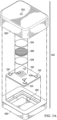
- FIGS. 3A-3B illustrate a first sensor 302 and a second sensor 304 comprising different filtering conditions (where the sensors 302 and 304 may be similar to the sensors 202 and 204).
- the first sensor 302 and the second sensor 304 may comprise a bottom housing 320 and a top housing 322, where the top housing 322 comprises an air inlet 323.
- the first sensor 302 and the second sensor 304 may also comprise a substrate 102 (e.g., as described in FIG. 1 ), as well as one or more diffusion channels 112 in the substrate 102 and one or more electrical contacts 120.
- the bottom housing 320 may comprise a cavity 330 configured to hold the substrate 102 (and other layers described in FIG. 1 ).
- the first sensor 302 and/or the second sensor 304 may comprise a dust filter 324 configured to prevent particulate matter from entering through the air inlet 323.
- the first sensor 302 comprises a filter 326 (which may be configured to filter the second (target) gas) located in the airflow pathway from the air inlet 323 to the diffusion channels 112.
- the filter 326 may comprise one or more materials configured to filter the second gas (as described above).
- the filter 326 may comprise a potassium permanganate impregnated glass fiber sheet.
- the first sensor 302 may also comprise a membrane 328, configured to hold the filter 326 in place so that it does not move around within the sensor housing 320 and 322.
- Some embodiments of the invention comprise a method for detecting a second target gas in the presence of a first target gas.
- a method may comprise detecting at least one target gas by a first sensor of a sensor assembly, where the first sensor may comprise a first operating condition.
- the method may comprise detecting at least one target gas by a second sensor, where the second sensor comprises a second operating condition, and the second operating condition is different than the first operating condition.
- the method may comprise comparing and/or processing the output signal from the first sensor and the second sensor to determine a concentration of at least one target gas.
- the method may comprise determining a concentration of a first target gas and determining a concentration of a second target gas.
- the method may comprise determining the concentration of the second target gas while in the presence of the first target gas.
- the first target gas may comprise CO
- the second target gas may comprise a volatile organic compound (VOC).
- the second target gas may comprise formaldehyde.
Landscapes
- Chemical & Material Sciences (AREA)
- Life Sciences & Earth Sciences (AREA)
- Health & Medical Sciences (AREA)
- Engineering & Computer Science (AREA)
- Analytical Chemistry (AREA)
- General Physics & Mathematics (AREA)
- Pathology (AREA)
- Physics & Mathematics (AREA)
- Immunology (AREA)
- Biochemistry (AREA)
- General Health & Medical Sciences (AREA)
- Combustion & Propulsion (AREA)
- Food Science & Technology (AREA)
- Medicinal Chemistry (AREA)
- Molecular Biology (AREA)
- Chemical Kinetics & Catalysis (AREA)
- Electrochemistry (AREA)
- Investigating Or Analyzing Materials By The Use Of Fluid Adsorption Or Reactions (AREA)
- Investigating Or Analyzing Materials By The Use Of Electric Means (AREA)
Description
- In monitoring for the presence of various gases, other gases (e.g., carbon monoxide (CO)) can be present that can also react within the sensor. For example, an electrode of the sensor can comprise a catalyst that can catalyze the reaction of both a target gas and an interferent gas (e.g., carbon monoxide). As a result, the presence of the interferent gas may create a cross-sensitivity in the sensor, resulting in a false impression that greater levels of the target gas are present in the ambient gases than are actually present. Due to the danger presented by the presence of various target gases, the threshold level for triggering an alarm can be relatively low, and the cross-sensitivity due to the presence of the interferent may be high enough to create a false alarm for the target gas sensor.
-
CN101571506A describes a formaldehyde technique field, specifically, relating to a kind of low concentration formaldehyde sensor. -
US2014/0174154A describes a method of selectively sensing the concentration of a target gas in polluted ambient air comprises the steps of providing a target gas sensor (220) sensitive to the target gas; providing a first gas flow derived from the ambient air, from which first flow the target gas is substantially removed. -
CN104614423A describes a portable formaldehyde detecting method, in particular to a hardware anti-interference circuit based on a subtractor and a digital filtering formaldehyde detecting method, belonging to the field of detecting technology. -
WO2019/056159A1 describes an electrochemical formaldehyde sensor and a method of detecting formaldehyde are disclosed. The electrochemical formaldehyde sensor may comprise a housing; an electrolyte disposed within the housing; and a plurality of electrodes in contact with the electrolyte within the housing, wherein the plurality of electrodes comprise a working electrode comprising iridium and an applied potential of between approximately 0.9 to IV relative to a reversible hydrogen electrode; and a counter electrode. - The invention is defined in the independent claims, to which reference should now be made. Advantageous features are set out in the dependent claims. In an embodiment, a method for determining the concentration of a second target gas while in the presence of a first target gas may comprise operating a first sensor under a first operating condition, wherein the first sensor is part of a sensor assembly; operating a second sensor under a second operating condition, wherein the second sensor is part of the sensor assembly, and wherein the second operating condition is different from the first operating condition; detecting at least one target gas by the first sensor; detecting at least one target gas by the second sensor; processing a signal output from the first sensor with a signal output from the second sensor; and determining a concentration of the first target gas and second target gas based on the processed output signals.
- In an embodiment, a sensor assembly configured to detect a second target gas in the presence of a first target gas may comprise a first sensor comprising a first operating condition; a second sensor comprising a second operating condition, wherein the first operating condition is different from the second operating condition; and a processor configured to receive a first output signal from the first sensor; receive a second output signal from the second sensor; process the received output signals by comparing them; and determine a concentration of the first target gas and second target gas based on the processed output signals.
- For a more complete understanding of the present disclosure, reference is now made to the following brief description, taken in connection with the accompanying drawings and detailed description, wherein like reference numerals represent like parts.
-
FIG. 1 illustrates a schematic diagram of a sensor according to an embodiment not forming part of the invention. -
FIG. 2 illustrates a sensor assembly according to an embodiment forming part of the invention. -
FIGS. 3A-3B illustrate exploded views of a first sensor and a second sensor according to an embodiment forming part of the invention. - It should be understood at the outset that although illustrative implementations of one or more embodiments are illustrated below, the disclosed systems and methods may be implemented using any number of techniques, whether currently known or not yet in existence. The disclosure should in no way be limited to the illustrative implementations, drawings, and techniques illustrated below, but may be modified within the scope of the appended claims.
- The following brief definition of terms shall apply throughout the application:
- The term "comprising" means including but not limited to, and should be interpreted in the manner it is typically used in the patent context;
- The phrases "in one embodiment," "according to one embodiment," and the like generally mean that the particular feature, structure, or characteristic following the phrase may be included in at least one embodiment of the present invention, and may be included in more than one embodiment of the present invention (importantly, such phrases do not necessarily refer to the same embodiment);
- If the specification describes something as "exemplary" or an "example," it should be understood that refers to a non-exclusive example;
- The terms "about" or "approximately" or the like, when used with a number, may mean that specific number, or alternatively, a range in proximity to the specific number, as understood by persons of skill in the art field; and
- If the specification states a component or feature "may," "can," "could," "should," "would," "preferably," "possibly," "typically," "optionally," "for example," "often," or "might" (or other such language) be included or have a characteristic, that particular component or feature is not required to be included or to have the characteristic. Such component or feature may be optionally included in some embodiments, or it may be excluded.
- Embodiments of the disclosure include systems and methods for detecting formaldehyde without a cross-sensitivity to carbon monoxide. Demand for domestic formaldehyde detectors (for personal use) may increase in areas with growth in the housing market, where people may be exposed to health damage due to exposure to low levels of formaldehyde, particularly in newly built homes (as formaldehyde exists in construction supplies and paints). Current detectors for formaldehyde typically suffer from cross-sensitivity to carbon monoxide (CO), where CO may exist in larger concentrations (when compared to the levels of formaldehyde). This cross-sensitivity may cause false alarms and prevent effective detection of formaldehyde. Also, high quality detectors currently available (that may not suffer from these cross-sensitivity issues) may be prohibitively expensive.
- Embodiments of the disclosure may employ two solid electrolyte sensors (SECS) operating under two different conditions. For example, the sensors may operate with two different bias potentials and/or with two different filters. The two sensors may respond differently when exposed to formaldehyde than they do when exposed to CO (and other cross-sensitivity gases), allowing the response related to formaldehyde to be isolated and detected. The low cost of the SECS may allow for more widespread domestic use, providing users with an affordable selective formaldehyde detector. Additionally, by comparing the outputs from the two sensors, noise in the signal(s) may be cancelled out, allowing for high resolution in the detected signal. This improved resolution may allow for lower concentrations of formaldehyde to be detected.
- It may be known in the art for a gas detector to use multiple sensors to provide selectivity. However, the disclosed embodiments comprise two sensors operating under different conditions, which may provide additional detection benefits, as described here. For example, a formaldehyde detector may comprise two different bias voltages applied to the two sensors. As another example, a formaldehyde detector may comprise different filters for the two sensors, which may provide increased resolution and selectivity for formaldehyde. These two examples of different operating conditions are used simultaneously in the same formaldehyde detector.
- The two-sensor design can be utilized by determining a difference in the response of the two sensors. The sensor response may vary due to the difference in bias voltage, which may provide a difference in sensitivity, response time, and noise towards gases (e.g., formaldehyde, CO, and other organic gases). The differences in the response of the two sensors can be interpreted to identify two or more gases. Noise in the signals may also be canceled out to achieve selectivity and high resolution.
- Referring now to
FIG. 1 , an exemplary embodiment of asensor 100 is shown, wherein thesensor 100 may comprise a plurality of layers attached to asubstrate 102. Thesubstrate 102 may comprise an alumina ceramic material, and may comprise one ormore diffusion channels 112 through the thickness of the substrate, where thediffusion channels 112 may allow gas flow into thesensor 100 from the surrounding environment. In some embodiments, thesensor 100 may comprise a first layer 104 (e.g., which may be a catalytic and/or electrode layer) configured to allow gas transfer into thesensor 100 and to the other layers of thesensor 100. In some embodiments, thefirst layer 104 may comprise a platinum (Pt) and ionic solution material. Although the diagram ofFIG. 1 only shows one electrode layer (i.e., catalytic layer, first layer 104), thesensor 100 may comprise two or three electrodes that are co-planar with each other. In some embodiments, thefirst layer 104 may comprise between one and three electrodes, which may include a sensing (or working) electrode, a counter electrode, and/or a reference electrode. - In some embodiments, the
sensor 100 may comprise a second layer 106 (e.g., which may be a humidification layer) configured to absorb any humidity within thesensor 100 which may prevent electrolyte from athird layer 108 from flooding the electrodes located within thefirst layer 104. In some embodiments, thesecond layer 106 may comprise silicon dioxide (SiO2) and an ionic solution material. In some embodiments, thesensor 100 may comprise a third layer 108 (e.g., which may comprise an electrolyte layer) configured to provide electrolyte to facilitate ionic conduction between the electrodes. Optionally, the third (electrolyte)layer 108 may also be configured to provide a reservoir of water to enable the sensor to be operated over a range of humidity conditions. In some embodiments, thethird layer 108 may comprise a mixture of sulfuric acid (H2SO4) and/or polyvinylpyrrolidone (PVPY), where the PVPY may serve to immobilize the sulfuric acid electrolyte. - In some embodiments, the
sensor 100 may comprise a fourth layer 110 (e.g., which may comprise a sealing layer) configured to seal with thesubstrate 102 to provide an air-tight seal for thesensor 100. Thissealing layer 110 may prevent air flow into thesensor 100 except for at thediffusion channels 112. In some embodiments, thesealing layer 110 may comprise a silicone material. In some embodiments, thesensor 100 may comprise one or moreelectrical contacts 120 that extend out of thesensor 100 to provide electrical connection(s) to other elements of a gas detector. In some embodiments, thesensor 100 may comprise up to threeelectrical contacts 120 for each of three electrodes that are located within thefirst layer 104. - Referring to
FIG. 2 , asensor assembly 200 is shown where thesensor assembly 200 may comprise at least part of a formaldehyde gas detector. Thesensor assembly 200 may comprise at least twosensors sensor assembly 200. In some embodiments, thesensors first sensor 202 may operate under a first condition and thesecond sensor 204 may operate under a second condition, wherein the outputs from thefirst sensor 202 and/or thesecond sensor 204 may be adjusted by adjusting the operating conditions. In some embodiments, thesensor assembly 200 may comprise a power source 212 (e.g., a battery) configured to power the elements of thesensor assembly 200. In some embodiments, thesensor assembly 200 may comprise one or more other components, such ascomponent 214, which may comprise additional sensor elements, communication elements, electrical elements, and/or anyother component 214 that may be located within thesensor assembly 200. - The different operating conditions applied to the
first sensor 202 and thesecond sensor 204 are a difference in bias voltage and a difference in filtering conditions. By comparing the signal outputs from the twosensors sensors - The
sensor assembly 200 may comprise a printed circuit board (PCB) 210 which may comprise one or more electrical connection elements configured to connect with thesensors PCB 210 may be configured to apply one or more controls to thesensors 202 and 204 (i.e., thePCB 210 may control one or more operating conditions of thesensors 202 and 204). For example, thePCB 210 comprises one or more elements configured to apply a bias voltage to one or both of thesensors PCB 210 may comprise a processor, a memory, and other elements as would be known to those skilled in the art. - In some embodiments of the
sensor assembly 200, thefirst sensor 202 comprises a first bias voltage while thesecond sensor 204 comprises a second bias voltage, where the second bias voltage is different from the first bias voltage. When the twosensors sensors sensors different sensors sensors sensors sensors - As an example, the first gas may comprise CO and the second gas may comprise formaldehyde. The sensor assembly may be configured to detect both CO and formaldehyde based on the outputs of the two
sensors - In some embodiments, only one sensor may have an applied bias voltage. In some embodiments, both sensors may have an applied bias voltage, where the applied bias voltage is different for the two sensors. In some embodiments, the
sensor assembly 200 may comprise more than two sensors (i.e., a plurality of sensors), where each sensor of the plurality of sensors may comprise a different bias voltage, and wherein the number of gases that can be detected by thesensor assembly 200 may be equal to the number of sensors. - Each of the two (or plurality) of
sensors diffusion channels 112 described inFIG. 1 ). In some embodiments, the gas channels to thesensors sensors - In the
sensor assembly 200, thesensors first sensor 202 may comprise a first filter while thesecond sensor 204 may comprise a second filter, wherein the first filter is configured to filter differently than the second filter. - As an example, the
sensors sensor assembly 200 may be configured to also detect a second gas. To accomplish detection of the second gas, thefirst sensor 202 may comprise a filter configured to capture/block the second gas, while thesecond sensor 204 does not comprise a filter. Therefore, thefirst sensor 202 may produce a signal in response to the first gas, while thesecond sensor 204 may produce a signal in response to the first gas and the second gas. - During operation, the output of the first sensor 202 (that does not include the second gas) may be compared to the output of the second sensor 204 (that does include the second gas) to determine a concentration of the second gas. In some embodiments, the signal generated by the sensor(s) 202 and 204 in response to the first gas may be significantly higher than the signal generated by the sensor(s) 202 and 204 in response to the second gas. In some embodiments, the first gas may typically be present in much higher concentrations than the second gas. As an example, the determined concentration of formaldehyde may be approximately 100 times less than the concentration of carbon monoxide. As an example, the ratio of the carbon monoxide concentration to the formaldehyde concentration may be approximately 100:1. As another example, the ratio of the carbon monoxide concentration to the formaldehyde concentration may be approximately 500:1. In some embodiments, it may be more difficult to filter the first gas from entering the sensor(s) 202 and 204 than to filter the second gas.
- Algorithms that may be used to process the sensor outputs may consider the specific type of sensor(s), the gas flow rate(s) to the sensor(s), the effects of the bias voltage(s) applied to the sensor(s), operating conditions (e.g., temperature, pressure, humidity), among other things. Testing may be completed on a prototype sensor assembly to determine the preferred or optimum algorithm processing. Additionally, the transient behavior of the
sensors sensors first sensor 202 may be slower than the gas flow into thesecond sensor 204 when thefirst sensor 202 comprises a filter and thesecond sensor 204 does not. - As an example,
FIGS. 3A-3B illustrate afirst sensor 302 and asecond sensor 304 comprising different filtering conditions (where thesensors sensors 202 and 204). Thefirst sensor 302 and thesecond sensor 304 may comprise abottom housing 320 and atop housing 322, where thetop housing 322 comprises anair inlet 323. Thefirst sensor 302 and thesecond sensor 304 may also comprise a substrate 102 (e.g., as described inFIG. 1 ), as well as one ormore diffusion channels 112 in thesubstrate 102 and one or moreelectrical contacts 120. Thebottom housing 320 may comprise acavity 330 configured to hold the substrate 102 (and other layers described inFIG. 1 ). In some embodiments, thefirst sensor 302 and/or thesecond sensor 304 may comprise adust filter 324 configured to prevent particulate matter from entering through theair inlet 323. - Additionally, the
first sensor 302 comprises a filter 326 (which may be configured to filter the second (target) gas) located in the airflow pathway from theair inlet 323 to thediffusion channels 112. Thefilter 326 may comprise one or more materials configured to filter the second gas (as described above). As an example, thefilter 326 may comprise a potassium permanganate impregnated glass fiber sheet. In some embodiments, thefirst sensor 302 may also comprise amembrane 328, configured to hold thefilter 326 in place so that it does not move around within thesensor housing - Some embodiments of the invention comprise a method for detecting a second target gas in the presence of a first target gas. A method may comprise detecting at least one target gas by a first sensor of a sensor assembly, where the first sensor may comprise a first operating condition. The method may comprise detecting at least one target gas by a second sensor, where the second sensor comprises a second operating condition, and the second operating condition is different than the first operating condition. The method may comprise comparing and/or processing the output signal from the first sensor and the second sensor to determine a concentration of at least one target gas. In some embodiments, the method may comprise determining a concentration of a first target gas and determining a concentration of a second target gas. In some embodiments, the method may comprise determining the concentration of the second target gas while in the presence of the first target gas. In some embodiments, the first target gas may comprise CO, while the second target gas may comprise a volatile organic compound (VOC). In some embodiments, the second target gas may comprise formaldehyde.
- While various embodiments in accordance with the principles disclosed herein have been shown and described above, modifications thereof may be made by one skilled in the art without departing from the scope defined by the independent claims. The embodiments described herein are representative only and are not intended to be limiting. Many variations, combinations, and modifications are possible and are within the scope of the claims.
- Accordingly, the scope of protection is not limited by the description set out above, but is defined by the claims which follow that scope including all equivalents of the subject matter of the claims. Each and every claim is incorporated as further disclosure into the specification and the claims are embodiment(s) of the present invention(s). Furthermore, any advantages and features described above may relate to specific embodiments, but shall not limit the application of such issued claims to processes and structures accomplishing any or all of the above advantages or having any or all of the above features.
- Use of broader terms such as "comprises," "includes," and "having" should be understood to provide support for narrower terms such as "consisting of," "consisting essentially of," and "comprised substantially of." Use of the terms "optionally," "may," "might," "possibly," and the like with respect to any element of an embodiment means that the element is not required, or alternatively, the element is required, both alternatives being within the scope of the embodiment(s). Also, references to examples are merely provided for illustrative purposes, and are not intended to be exclusive.
- While several embodiments have been provided in the present disclosure, it should be understood that the disclosed systems and methods may be embodied in many other specific forms without departing from the scope as defined by the independent claims. The present examples are to be considered as illustrative and not restrictive, and the intention is not to be limited to the details given herein. For example, the various elements or components may be combined or integrated in another system or certain features may be omitted or not implemented.
- Also, techniques, systems, subsystems, and methods described and illustrated in the various embodiments as discrete or separate may be combined or integrated with other systems, modules, techniques, or methods without departing from the scope of the present disclosure. Other items shown or discussed as directly coupled or communicating with each other may be indirectly coupled or communicating through some interface, device, or intermediate component, whether electrically, mechanically, or otherwise.
Claims (11)
- A method for determining the concentration of a second target gas while in the presence of a first target gas, the method comprising:operating a first sensor (202) under a first operating condition, wherein the first sensor is part of a sensor assembly (200);operating a second sensor (204) under a second operating condition, wherein the second sensor is part of the sensor assembly (200); and wherein:the second operating condition is different from the first operating condition, andthe first operating condition comprises a first bias voltage and the second operating condition comprises a second bias voltage, the second bias voltage being different from the first bias voltage, wherein the first sensor comprises a first filter and the second sensor comprises a second filter different from the first filter, and wherein the first sensor comprises a membrane (328) configured to hold the first filter;detecting at least one target gas by the first sensor;detecting at least one target gas by the second sensor;processing a signal output from the first sensor with a signal output from the second sensor; anddetermining a concentration of the first target gas and determining a concentration of the second target gas based on the processed output signals.
- The method of claim 1, wherein the first target gas comprises carbon monoxide.
- The method of claim 1, wherein the second target gas comprises a volatile organic compound.
- The method of claim 1, wherein the second target gas comprises formaldehyde.
- The method of claim 1, wherein one of the first bias voltage and the second bias voltage comprises a zero bias voltage.
- The method of claim 1, wherein one of the first bias voltage and the second bias voltage comprises approximately 300 mV.
- The method of claim 1, wherein one of the first bias voltage and the second bias voltage comprises a bias voltage between approximately 0 and approximately 500 mV.
- The method of claim 1, wherein the first operating condition comprises a first filtering condition and the second operating condition comprises a second filtering condition.
- A sensor assembly (200) configured to detect a second target gas in the presence of a first target gas, the sensor assembly comprising:a first sensor (202) comprising a first operating condition;a second sensor (204) comprising a second operating condition,wherein the first sensor (202) comprises a first filter and the second sensor (204) comprises a second filter different from the first filter;a processor (210) configured to:receive a first output signal from the first sensor (202);receive a second output signal from the second sensor (204);characterised in that the processor (210) is further configured to:process the received output signals by comparing them; anddetermine a concentration of the first target gas and determine a concentration of the second target gas based on the processed output signals and the first operating condition comprises a first bias voltage and the second operating condition comprises a second bias voltage, the second bias voltage being different from the first bias voltage, and wherein the first sensor (202) comprises a membrane (328) configured to hold the first filter.
- The sensor assembly (200) of claim 9, wherein the processor (210) is configured to determine the difference between the two output signals.
- The sensor assembly (200) of claim 9, wherein the first operating condition allows the first sensor (202) to detect the first target gas, and wherein the second operating condition allows the second sensor (204) to detect the first target gas in combination with the second target gas.
Applications Claiming Priority (1)
| Application Number | Priority Date | Filing Date | Title |
|---|---|---|---|
| PCT/CN2017/107755 WO2019080025A1 (en) | 2017-10-26 | 2017-10-26 | Systems and methods for using a plurality of solid electrolyte sensors for a selective, low resolution formaldehyde detector |
Publications (3)
| Publication Number | Publication Date |
|---|---|
| EP3701255A1 EP3701255A1 (en) | 2020-09-02 |
| EP3701255A4 EP3701255A4 (en) | 2021-06-23 |
| EP3701255B1 true EP3701255B1 (en) | 2024-12-11 |
Family
ID=66247678
Family Applications (1)
| Application Number | Title | Priority Date | Filing Date |
|---|---|---|---|
| EP17929749.4A Active EP3701255B1 (en) | 2017-10-26 | 2017-10-26 | Systems and methods for using a plurality of solid electrolyte sensors for a selective, low resolution formaldehyde detector |
Country Status (4)
| Country | Link |
|---|---|
| US (1) | US20210172899A1 (en) |
| EP (1) | EP3701255B1 (en) |
| CN (2) | CN111386457B (en) |
| WO (1) | WO2019080025A1 (en) |
Families Citing this family (1)
| Publication number | Priority date | Publication date | Assignee | Title |
|---|---|---|---|---|
| DE102021126528A1 (en) * | 2020-10-14 | 2022-04-14 | Hyundai Kefico Corporation | GAS SOR |
Citations (1)
| Publication number | Priority date | Publication date | Assignee | Title |
|---|---|---|---|---|
| US20170241931A1 (en) * | 2014-09-30 | 2017-08-24 | Sharp Kabushiki Kaisha | Sensing system |
Family Cites Families (15)
| Publication number | Priority date | Publication date | Assignee | Title |
|---|---|---|---|---|
| US3659100A (en) * | 1970-08-14 | 1972-04-25 | Geomet | System and method of air pollution monitoring utilizing chemiluminescence reactions |
| GB0317131D0 (en) * | 2003-07-22 | 2003-08-27 | City Tech | Electrochemical gas sensor |
| JP2005083950A (en) * | 2003-09-10 | 2005-03-31 | Yazaki Corp | Voc sensor and voc detector |
| CN101571506B (en) * | 2008-04-29 | 2016-02-24 | 华瑞科学仪器(上海)有限公司 | Formaldehyde sensor |
| DE102009015121B4 (en) * | 2009-03-31 | 2012-10-31 | Siemens Aktiengesellschaft | Selective carbon monoxide detector and method of operation of the detector |
| CN101776640A (en) * | 2010-02-01 | 2010-07-14 | 北京亚都空气污染治理技术有限公司 | Formaldehyde gas sensor |
| JP6100771B2 (en) | 2011-07-13 | 2017-03-22 | コーニンクレッカ フィリップス エヌ ヴェKoninklijke Philips N.V. | Gas detector |
| CN105987939A (en) * | 2015-02-04 | 2016-10-05 | 深圳德士特智慧科技有限公司 | Multipath formaldehyde collection and intelligent calibration system as well as calibration method thereof |
| CN104614423B (en) * | 2015-02-06 | 2017-09-29 | 张娇婷 | Electrochemistry formaldehyde sensor anti-jamming circuit design based on subtracter |
| US10203302B2 (en) * | 2015-08-13 | 2019-02-12 | Carrier Corporation | State of health monitoring and restoration of electrochemical sensor |
| EP3223005A1 (en) * | 2016-03-22 | 2017-09-27 | Alphasense Limited | Electrochemical gas sensing apparatus and methods |
| US20180136182A1 (en) * | 2016-11-14 | 2018-05-17 | Oriental System Technology Inc. | Accurate multi-gas analyzer |
| CN106872540A (en) * | 2017-04-21 | 2017-06-20 | 马刚 | A kind of formaldehyde, ammonia detection means and its detection method |
| KR101759176B1 (en) * | 2017-04-26 | 2017-07-19 | 한국생산기술연구원 | Method for detecting chemical substances using impedance analysis |
| WO2019056159A1 (en) | 2017-09-19 | 2019-03-28 | Honeywell International Inc. | Improved electrochemical sensor and method for detecting formaldehyde by regulating voltage to reduce cross-sensitivity |
-
2017
- 2017-10-26 EP EP17929749.4A patent/EP3701255B1/en active Active
- 2017-10-26 CN CN201780097246.7A patent/CN111386457B/en active Active
- 2017-10-26 CN CN202211661404.6A patent/CN115718126B/en active Active
- 2017-10-26 US US16/762,872 patent/US20210172899A1/en not_active Abandoned
- 2017-10-26 WO PCT/CN2017/107755 patent/WO2019080025A1/en not_active Ceased
Patent Citations (1)
| Publication number | Priority date | Publication date | Assignee | Title |
|---|---|---|---|---|
| US20170241931A1 (en) * | 2014-09-30 | 2017-08-24 | Sharp Kabushiki Kaisha | Sensing system |
Also Published As
| Publication number | Publication date |
|---|---|
| CN111386457A (en) | 2020-07-07 |
| WO2019080025A1 (en) | 2019-05-02 |
| CN115718126A (en) | 2023-02-28 |
| EP3701255A4 (en) | 2021-06-23 |
| US20210172899A1 (en) | 2021-06-10 |
| EP3701255A1 (en) | 2020-09-02 |
| CN111386457B (en) | 2023-01-03 |
| CN115718126B (en) | 2025-11-11 |
Similar Documents
| Publication | Publication Date | Title |
|---|---|---|
| US8920627B2 (en) | Selective detector for carbon monoxide | |
| US5932079A (en) | Electrochemical multigas sensor | |
| JP3871497B2 (en) | Gas sensor | |
| US4913792A (en) | Flammable-gas sensor | |
| US4326927A (en) | Method and device for the detection and measurement of electrochemically active compounds | |
| US20110212376A1 (en) | Amperometric sensor | |
| JP2001124716A (en) | Gas sensor | |
| WO2019056159A1 (en) | Improved electrochemical sensor and method for detecting formaldehyde by regulating voltage to reduce cross-sensitivity | |
| US20190086351A1 (en) | Gas sensor | |
| US20110138881A1 (en) | Sensor apparatus and method therefor | |
| US20210172899A1 (en) | Systems and methods for using a plurality of solid electrolyte sensors for a selective, low resolution formaldehyde detector | |
| CN120778833A (en) | Multichannel electrochemical detection electrode, electrochemical sensor and detection method | |
| JP4516195B2 (en) | Constant potential electrolytic gas sensor | |
| Sekhar et al. | Independent testing and validation of prototype hydrogen sensors | |
| JP4465677B2 (en) | Hydrogen gas detector | |
| JP2007071642A (en) | Hydrogen gas detection element and hydrogen gas detection device | |
| US11209384B2 (en) | Electrochemical sensor containing an internal reference cell | |
| US10996189B2 (en) | Method of venting oxygen sensors | |
| JP4445275B2 (en) | Gas detector | |
| KR20210116313A (en) | Configurable electrochemical gas sensor | |
| WO1995030145A1 (en) | Gas analysis apparatus | |
| US20250155398A1 (en) | Gas sensor | |
| JP3018761B2 (en) | Electrochemical gas sensor | |
| TW200530579A (en) | Electrochemical sensor | |
| JPH08292169A (en) | Gas or volatile substance detector |
Legal Events
| Date | Code | Title | Description |
|---|---|---|---|
| STAA | Information on the status of an ep patent application or granted ep patent |
Free format text: STATUS: THE INTERNATIONAL PUBLICATION HAS BEEN MADE |
|
| PUAI | Public reference made under article 153(3) epc to a published international application that has entered the european phase |
Free format text: ORIGINAL CODE: 0009012 |
|
| STAA | Information on the status of an ep patent application or granted ep patent |
Free format text: STATUS: REQUEST FOR EXAMINATION WAS MADE |
|
| 17P | Request for examination filed |
Effective date: 20200521 |
|
| AK | Designated contracting states |
Kind code of ref document: A1 Designated state(s): AL AT BE BG CH CY CZ DE DK EE ES FI FR GB GR HR HU IE IS IT LI LT LU LV MC MK MT NL NO PL PT RO RS SE SI SK SM TR |
|
| AX | Request for extension of the european patent |
Extension state: BA ME |
|
| DAV | Request for validation of the european patent (deleted) | ||
| DAX | Request for extension of the european patent (deleted) | ||
| A4 | Supplementary search report drawn up and despatched |
Effective date: 20210527 |
|
| RIC1 | Information provided on ipc code assigned before grant |
Ipc: G01N 27/26 20060101AFI20210520BHEP Ipc: G01N 27/404 20060101ALI20210520BHEP Ipc: G01N 33/00 20060101ALI20210520BHEP |
|
| STAA | Information on the status of an ep patent application or granted ep patent |
Free format text: STATUS: EXAMINATION IS IN PROGRESS |
|
| 17Q | First examination report despatched |
Effective date: 20220113 |
|
| GRAP | Despatch of communication of intention to grant a patent |
Free format text: ORIGINAL CODE: EPIDOSNIGR1 |
|
| STAA | Information on the status of an ep patent application or granted ep patent |
Free format text: STATUS: GRANT OF PATENT IS INTENDED |
|
| INTG | Intention to grant announced |
Effective date: 20240708 |
|
| GRAS | Grant fee paid |
Free format text: ORIGINAL CODE: EPIDOSNIGR3 |
|
| GRAA | (expected) grant |
Free format text: ORIGINAL CODE: 0009210 |
|
| STAA | Information on the status of an ep patent application or granted ep patent |
Free format text: STATUS: THE PATENT HAS BEEN GRANTED |
|
| AK | Designated contracting states |
Kind code of ref document: B1 Designated state(s): AL AT BE BG CH CY CZ DE DK EE ES FI FR GB GR HR HU IE IS IT LI LT LU LV MC MK MT NL NO PL PT RO RS SE SI SK SM TR |
|
| REG | Reference to a national code |
Ref country code: GB Ref legal event code: FG4D |
|
| REG | Reference to a national code |
Ref country code: CH Ref legal event code: EP |
|
| REG | Reference to a national code |
Ref country code: DE Ref legal event code: R096 Ref document number: 602017086772 Country of ref document: DE |
|
| REG | Reference to a national code |
Ref country code: IE Ref legal event code: FG4D |
|
| REG | Reference to a national code |
Ref country code: LT Ref legal event code: MG9D |
|
| PG25 | Lapsed in a contracting state [announced via postgrant information from national office to epo] |
Ref country code: HR Free format text: LAPSE BECAUSE OF FAILURE TO SUBMIT A TRANSLATION OF THE DESCRIPTION OR TO PAY THE FEE WITHIN THE PRESCRIBED TIME-LIMIT Effective date: 20241211 |
|
| PG25 | Lapsed in a contracting state [announced via postgrant information from national office to epo] |
Ref country code: FI Free format text: LAPSE BECAUSE OF FAILURE TO SUBMIT A TRANSLATION OF THE DESCRIPTION OR TO PAY THE FEE WITHIN THE PRESCRIBED TIME-LIMIT Effective date: 20241211 |
|
| PG25 | Lapsed in a contracting state [announced via postgrant information from national office to epo] |
Ref country code: BG Free format text: LAPSE BECAUSE OF FAILURE TO SUBMIT A TRANSLATION OF THE DESCRIPTION OR TO PAY THE FEE WITHIN THE PRESCRIBED TIME-LIMIT Effective date: 20241211 |
|
| REG | Reference to a national code |
Ref country code: NL Ref legal event code: MP Effective date: 20241211 |
|
| PG25 | Lapsed in a contracting state [announced via postgrant information from national office to epo] |
Ref country code: ES Free format text: LAPSE BECAUSE OF FAILURE TO SUBMIT A TRANSLATION OF THE DESCRIPTION OR TO PAY THE FEE WITHIN THE PRESCRIBED TIME-LIMIT Effective date: 20241211 |
|
| PG25 | Lapsed in a contracting state [announced via postgrant information from national office to epo] |
Ref country code: NO Free format text: LAPSE BECAUSE OF FAILURE TO SUBMIT A TRANSLATION OF THE DESCRIPTION OR TO PAY THE FEE WITHIN THE PRESCRIBED TIME-LIMIT Effective date: 20250311 |
|
| PG25 | Lapsed in a contracting state [announced via postgrant information from national office to epo] |
Ref country code: LV Free format text: LAPSE BECAUSE OF FAILURE TO SUBMIT A TRANSLATION OF THE DESCRIPTION OR TO PAY THE FEE WITHIN THE PRESCRIBED TIME-LIMIT Effective date: 20241211 Ref country code: GR Free format text: LAPSE BECAUSE OF FAILURE TO SUBMIT A TRANSLATION OF THE DESCRIPTION OR TO PAY THE FEE WITHIN THE PRESCRIBED TIME-LIMIT Effective date: 20250312 |
|
| PG25 | Lapsed in a contracting state [announced via postgrant information from national office to epo] |
Ref country code: RS Free format text: LAPSE BECAUSE OF FAILURE TO SUBMIT A TRANSLATION OF THE DESCRIPTION OR TO PAY THE FEE WITHIN THE PRESCRIBED TIME-LIMIT Effective date: 20250311 |
|
| PG25 | Lapsed in a contracting state [announced via postgrant information from national office to epo] |
Ref country code: NL Free format text: LAPSE BECAUSE OF FAILURE TO SUBMIT A TRANSLATION OF THE DESCRIPTION OR TO PAY THE FEE WITHIN THE PRESCRIBED TIME-LIMIT Effective date: 20241211 |
|
| REG | Reference to a national code |
Ref country code: AT Ref legal event code: MK05 Ref document number: 1750752 Country of ref document: AT Kind code of ref document: T Effective date: 20241211 |
|
| PG25 | Lapsed in a contracting state [announced via postgrant information from national office to epo] |
Ref country code: SM Free format text: LAPSE BECAUSE OF FAILURE TO SUBMIT A TRANSLATION OF THE DESCRIPTION OR TO PAY THE FEE WITHIN THE PRESCRIBED TIME-LIMIT Effective date: 20241211 |
|
| PG25 | Lapsed in a contracting state [announced via postgrant information from national office to epo] |
Ref country code: PL Free format text: LAPSE BECAUSE OF FAILURE TO SUBMIT A TRANSLATION OF THE DESCRIPTION OR TO PAY THE FEE WITHIN THE PRESCRIBED TIME-LIMIT Effective date: 20241211 |
|
| PG25 | Lapsed in a contracting state [announced via postgrant information from national office to epo] |
Ref country code: IS Free format text: LAPSE BECAUSE OF FAILURE TO SUBMIT A TRANSLATION OF THE DESCRIPTION OR TO PAY THE FEE WITHIN THE PRESCRIBED TIME-LIMIT Effective date: 20250411 |
|
| PG25 | Lapsed in a contracting state [announced via postgrant information from national office to epo] |
Ref country code: PT Free format text: LAPSE BECAUSE OF FAILURE TO SUBMIT A TRANSLATION OF THE DESCRIPTION OR TO PAY THE FEE WITHIN THE PRESCRIBED TIME-LIMIT Effective date: 20250411 |
|
| PG25 | Lapsed in a contracting state [announced via postgrant information from national office to epo] |
Ref country code: EE Free format text: LAPSE BECAUSE OF FAILURE TO SUBMIT A TRANSLATION OF THE DESCRIPTION OR TO PAY THE FEE WITHIN THE PRESCRIBED TIME-LIMIT Effective date: 20241211 |
|
| PG25 | Lapsed in a contracting state [announced via postgrant information from national office to epo] |
Ref country code: RO Free format text: LAPSE BECAUSE OF FAILURE TO SUBMIT A TRANSLATION OF THE DESCRIPTION OR TO PAY THE FEE WITHIN THE PRESCRIBED TIME-LIMIT Effective date: 20241211 Ref country code: AT Free format text: LAPSE BECAUSE OF FAILURE TO SUBMIT A TRANSLATION OF THE DESCRIPTION OR TO PAY THE FEE WITHIN THE PRESCRIBED TIME-LIMIT Effective date: 20241211 |
|
| PG25 | Lapsed in a contracting state [announced via postgrant information from national office to epo] |
Ref country code: SK Free format text: LAPSE BECAUSE OF FAILURE TO SUBMIT A TRANSLATION OF THE DESCRIPTION OR TO PAY THE FEE WITHIN THE PRESCRIBED TIME-LIMIT Effective date: 20241211 |
|
| PG25 | Lapsed in a contracting state [announced via postgrant information from national office to epo] |
Ref country code: CZ Free format text: LAPSE BECAUSE OF FAILURE TO SUBMIT A TRANSLATION OF THE DESCRIPTION OR TO PAY THE FEE WITHIN THE PRESCRIBED TIME-LIMIT Effective date: 20241211 |
|
| PG25 | Lapsed in a contracting state [announced via postgrant information from national office to epo] |
Ref country code: IT Free format text: LAPSE BECAUSE OF FAILURE TO SUBMIT A TRANSLATION OF THE DESCRIPTION OR TO PAY THE FEE WITHIN THE PRESCRIBED TIME-LIMIT Effective date: 20241211 |
|
| PG25 | Lapsed in a contracting state [announced via postgrant information from national office to epo] |
Ref country code: SE Free format text: LAPSE BECAUSE OF FAILURE TO SUBMIT A TRANSLATION OF THE DESCRIPTION OR TO PAY THE FEE WITHIN THE PRESCRIBED TIME-LIMIT Effective date: 20241211 |
|
| REG | Reference to a national code |
Ref country code: DE Ref legal event code: R097 Ref document number: 602017086772 Country of ref document: DE |
|
| PG25 | Lapsed in a contracting state [announced via postgrant information from national office to epo] |
Ref country code: DK Free format text: LAPSE BECAUSE OF FAILURE TO SUBMIT A TRANSLATION OF THE DESCRIPTION OR TO PAY THE FEE WITHIN THE PRESCRIBED TIME-LIMIT Effective date: 20241211 |
|
| PLBE | No opposition filed within time limit |
Free format text: ORIGINAL CODE: 0009261 |
|
| STAA | Information on the status of an ep patent application or granted ep patent |
Free format text: STATUS: NO OPPOSITION FILED WITHIN TIME LIMIT |
|
| REG | Reference to a national code |
Ref country code: CH Ref legal event code: L10 Free format text: ST27 STATUS EVENT CODE: U-0-0-L10-L00 (AS PROVIDED BY THE NATIONAL OFFICE) Effective date: 20251022 |
|
| 26N | No opposition filed |
Effective date: 20250912 |
|
| PGFP | Annual fee paid to national office [announced via postgrant information from national office to epo] |
Ref country code: DE Payment date: 20251028 Year of fee payment: 9 |
|
| PGFP | Annual fee paid to national office [announced via postgrant information from national office to epo] |
Ref country code: GB Payment date: 20251023 Year of fee payment: 9 |
|
| REG | Reference to a national code |
Ref country code: CH Ref legal event code: H13 Free format text: ST27 STATUS EVENT CODE: U-0-0-H10-H13 (AS PROVIDED BY THE NATIONAL OFFICE) Effective date: 20260527 |
|
| PG25 | Lapsed in a contracting state [announced via postgrant information from national office to epo] |
Ref country code: LU Free format text: LAPSE BECAUSE OF NON-PAYMENT OF DUE FEES Effective date: 20251026 |
|
| REG | Reference to a national code |
Ref country code: BE Ref legal event code: MM Effective date: 20251031 |
|
| PG25 | Lapsed in a contracting state [announced via postgrant information from national office to epo] |
Ref country code: LT Free format text: LAPSE BECAUSE OF FAILURE TO SUBMIT A TRANSLATION OF THE DESCRIPTION OR TO PAY THE FEE WITHIN THE PRESCRIBED TIME-LIMIT Effective date: 20241211 |
|
| PG25 | Lapsed in a contracting state [announced via postgrant information from national office to epo] |
Ref country code: MC Free format text: LAPSE BECAUSE OF FAILURE TO SUBMIT A TRANSLATION OF THE DESCRIPTION OR TO PAY THE FEE WITHIN THE PRESCRIBED TIME-LIMIT Effective date: 20241211 |
|
| PG25 | Lapsed in a contracting state [announced via postgrant information from national office to epo] |
Ref country code: BE Free format text: LAPSE BECAUSE OF NON-PAYMENT OF DUE FEES Effective date: 20251031 Ref country code: CH Free format text: LAPSE BECAUSE OF NON-PAYMENT OF DUE FEES Effective date: 20251031 |
|
| PG25 | Lapsed in a contracting state [announced via postgrant information from national office to epo] |
Ref country code: FR Free format text: LAPSE BECAUSE OF NON-PAYMENT OF DUE FEES Effective date: 20251031 |