EP3700313A1 - Cooling system, module, and device - Google Patents
Cooling system, module, and device Download PDFInfo
- Publication number
- EP3700313A1 EP3700313A1 EP18869196.8A EP18869196A EP3700313A1 EP 3700313 A1 EP3700313 A1 EP 3700313A1 EP 18869196 A EP18869196 A EP 18869196A EP 3700313 A1 EP3700313 A1 EP 3700313A1
- Authority
- EP
- European Patent Office
- Prior art keywords
- tube
- discharge
- supply
- connection
- tubes
- Prior art date
- Legal status (The legal status is an assumption and is not a legal conclusion. Google has not performed a legal analysis and makes no representation as to the accuracy of the status listed.)
- Withdrawn
Links
Images


Classifications
-
- H—ELECTRICITY
- H05—ELECTRIC TECHNIQUES NOT OTHERWISE PROVIDED FOR
- H05K—PRINTED CIRCUITS; CASINGS OR CONSTRUCTIONAL DETAILS OF ELECTRIC APPARATUS; MANUFACTURE OF ASSEMBLAGES OF ELECTRICAL COMPONENTS
- H05K7/00—Constructional details common to different types of electric apparatus
- H05K7/20—Modifications to facilitate cooling, ventilating, or heating
- H05K7/20218—Modifications to facilitate cooling, ventilating, or heating using a liquid coolant without phase change in electronic enclosures
- H05K7/20272—Accessories for moving fluid, for expanding fluid, for connecting fluid conduits, for distributing fluid, for removing gas or for preventing leakage, e.g. pumps, tanks or manifolds
-
- F—MECHANICAL ENGINEERING; LIGHTING; HEATING; WEAPONS; BLASTING
- F28—HEAT EXCHANGE IN GENERAL
- F28F—DETAILS OF HEAT-EXCHANGE AND HEAT-TRANSFER APPARATUS, OF GENERAL APPLICATION
- F28F9/00—Casings; Header boxes; Auxiliary supports for elements; Auxiliary members within casings
- F28F9/02—Header boxes; End plates
- F28F9/0246—Arrangements for connecting header boxes with flow lines
-
- F—MECHANICAL ENGINEERING; LIGHTING; HEATING; WEAPONS; BLASTING
- F28—HEAT EXCHANGE IN GENERAL
- F28F—DETAILS OF HEAT-EXCHANGE AND HEAT-TRANSFER APPARATUS, OF GENERAL APPLICATION
- F28F9/00—Casings; Header boxes; Auxiliary supports for elements; Auxiliary members within casings
- F28F9/02—Header boxes; End plates
- F28F9/026—Header boxes; End plates with static flow control means, e.g. with means for uniformly distributing heat exchange media into conduits
- F28F9/027—Header boxes; End plates with static flow control means, e.g. with means for uniformly distributing heat exchange media into conduits in the form of distribution pipes
- F28F9/0275—Header boxes; End plates with static flow control means, e.g. with means for uniformly distributing heat exchange media into conduits in the form of distribution pipes with multiple branch pipes
-
- G—PHYSICS
- G06—COMPUTING OR CALCULATING; COUNTING
- G06F—ELECTRIC DIGITAL DATA PROCESSING
- G06F1/00—Details not covered by groups G06F3/00 - G06F13/00 and G06F21/00
- G06F1/16—Constructional details or arrangements
- G06F1/20—Cooling means
-
- H—ELECTRICITY
- H05—ELECTRIC TECHNIQUES NOT OTHERWISE PROVIDED FOR
- H05K—PRINTED CIRCUITS; CASINGS OR CONSTRUCTIONAL DETAILS OF ELECTRIC APPARATUS; MANUFACTURE OF ASSEMBLAGES OF ELECTRICAL COMPONENTS
- H05K7/00—Constructional details common to different types of electric apparatus
- H05K7/20—Modifications to facilitate cooling, ventilating, or heating
- H05K7/20536—Modifications to facilitate cooling, ventilating, or heating for racks or cabinets of standardised dimensions, e.g. electronic racks for aircraft or telecommunication equipment
- H05K7/20627—Liquid coolant without phase change
- H05K7/20636—Liquid coolant without phase change within sub-racks for removing heat from electronic boards
-
- H—ELECTRICITY
- H05—ELECTRIC TECHNIQUES NOT OTHERWISE PROVIDED FOR
- H05K—PRINTED CIRCUITS; CASINGS OR CONSTRUCTIONAL DETAILS OF ELECTRIC APPARATUS; MANUFACTURE OF ASSEMBLAGES OF ELECTRICAL COMPONENTS
- H05K7/00—Constructional details common to different types of electric apparatus
- H05K7/20—Modifications to facilitate cooling, ventilating, or heating
- H05K7/20709—Modifications to facilitate cooling, ventilating, or heating for server racks or cabinets; for data centers, e.g. 19-inch computer racks
- H05K7/20763—Liquid cooling without phase change
-
- H—ELECTRICITY
- H05—ELECTRIC TECHNIQUES NOT OTHERWISE PROVIDED FOR
- H05K—PRINTED CIRCUITS; CASINGS OR CONSTRUCTIONAL DETAILS OF ELECTRIC APPARATUS; MANUFACTURE OF ASSEMBLAGES OF ELECTRICAL COMPONENTS
- H05K7/00—Constructional details common to different types of electric apparatus
- H05K7/20—Modifications to facilitate cooling, ventilating, or heating
- H05K7/20709—Modifications to facilitate cooling, ventilating, or heating for server racks or cabinets; for data centers, e.g. 19-inch computer racks
- H05K7/20763—Liquid cooling without phase change
- H05K7/20781—Liquid cooling without phase change within cabinets for removing heat from server blades
-
- H—ELECTRICITY
- H10—SEMICONDUCTOR DEVICES; ELECTRIC SOLID-STATE DEVICES NOT OTHERWISE PROVIDED FOR
- H10W—GENERIC PACKAGES, INTERCONNECTIONS, CONNECTORS OR OTHER CONSTRUCTIONAL DETAILS OF DEVICES COVERED BY CLASS H10
- H10W40/00—Arrangements for thermal protection or thermal control
- H10W40/40—Arrangements for thermal protection or thermal control involving heat exchange by flowing fluids
- H10W40/47—Arrangements for thermal protection or thermal control involving heat exchange by flowing fluids by flowing liquids, e.g. forced water cooling
Definitions
- the present invention relates to a cooling system, a module, and a device.
- Patent Document 1 discloses a rack for enclosure liquid-cooled electronic units.
- the rack comprises fluid connectors for supplying and discharging coolant with respect to the electronic units.
- the electronic units comprise unit-side fluid connectors that are connected to the fluid connectors in the rack.
- the unit-side fluid connectors are configured so that supply-side connectors and discharge-side connectors are inserted and withdrawn together with respect to the fluid connectors in the rack.
- Patent Document 1 Japanese Unexamined Patent Application, First Publication No 2013-38448
- Patent Document 1 does not disclose a configuration in which the supply-side connectors and the discharge-side connectors are separately inserted and withdrawn. Therefore, it does not disclose, in a configuration in which the supply-side connectors and the discharge-side connectors can be separately inserted and withdrawn, a configuration for preventing erroneous connections of the supply-side connectors and the discharge-side connectors.
- the present invention provides a cooling system, a module, and a device that prevent erroneous connections of supply connection tubes and discharge connection tubes in a structure in which the supply connection tubes and the discharge connection tubes can be independently inserted and withdrawn.
- the cooling system includes a cooling unit that cools a heat-generating component; a supply connection tube that is connected to the cooling unit and that supplies a cooling medium to the cooling unit; and a discharge connection tube that is connected to the cooling unit and that discharges the cooling medium from the cooling unit, wherein the supply connection tube and the discharge connection tube have different lengths.
- the module according to the present invention includes a substrate on which a heat-generating component is provided; a cooling unit that cools the heat-generating component; a supply connection tube that is connected to the cooling unit and that supplies a cooling medium to the cooling unit; and a discharge connection tube that is connected to the cooling unit and that discharges the cooling medium from the cooling unit, wherein the supply connection tube and the discharge connection tube have different lengths.
- the device includes the module as described above; a supply tube to which the supply connection tube is connected; and a discharge tube to which the discharge connection tube is connected; wherein the supply tube and the discharge tube are provided at positions such that a distance between the cooling unit and the supply tube and a distance between the cooling unit and the discharge tube are different.
- the cooling system, module, and device of the present invention prevent erroneous connections of supply connection tubes and discharge connection tubes in a structure in which the supply connection tubes and the discharge connection tubes can be independently inserted and withdrawn.
- the cooling system 5 comprises at least a cooling unit 1, a supply connection tube 2 and a discharge connection tube 3.
- the cooling unit 1 cools a heat-generating component 4.
- the discharge connection tube 3 is connected to the cooling unit 1.
- the discharge connection tube 3 discharges the cooling medium from the cooling unit 1.
- the supply connection tube 2 and the discharge connection tube 3 have mutually different lengths.
- a heat-generating component 4 is mounted on the substrate 7.
- the cooling unit 1 cools the heat-generating component 4.
- the supply connection tube 2 is connected to the cooling unit 1.
- the supply connection tube 2 supplies a cooling medium to the cooling unit 1.
- the discharge connection tube 3 is connected to the cooling unit 1.
- the discharge connection tube 3 discharges the cooling medium from the cooling unit 1.
- the supply connection tube 2 and the discharge connection tube 3 have mutually different lengths.
- the supply connection tube 2 and the discharge connection tube 3 have different lengths, so the supply connection tube 2 and the discharge connection tube 3 can be easily and reliably distinguished visually.
- the supply connection tube 2 and the discharge connection tube 3 can be easily and reliably distinguished visually. Therefore, it is possible to suppress situations in which the supply connection tube 2 and the discharge connection tube 3 are misrecognized and confused with each other. Therefore, in a structure in which the supply connection tube 2 and the discharge connection tube 3 can be independently inserted and withdrawn, it is possible to prevent erroneous connections of the supply connection tube 2 and the discharge connection tube 3.
- Fig. 1 and Fig. 2 illustrate the supply connection tube 2 as being longer than the discharge connection tube 3, but there is no such limitation.
- the discharge connection tube 3 may be made longer than the supply connection tube 2.
- the device 10 comprises at least a module 6, a supply tube 8 and a discharge tube 9.
- the module 6 is similar to that indicated in the above-described second embodiment.
- the module 6 comprises at least a substrate 7, a cooling unit 1, a supply connection tube 2 and a discharge connection tube 3.
- a heat-generating component 4 is mounted on the substrate 7.
- the cooling unit 1 cools the heat-generating component 4.
- the supply connection tube 2 is connected to the cooling unit 1.
- the supply connection tube 2 supplies a cooling medium to the cooling unit 1.
- the discharge connection tube 3 is connected to the cooling unit 1.
- the discharge connection tube 3 discharges the cooling medium from the cooling unit 1.
- the supply connection tube 2 and the discharge connection tube 3 have mutually different lengths.
- the supply connection tube 2 is connected to the supply tube 8.
- the discharge connection tube 3 is connected to the discharge tube 9.
- the supply tube 8 and the discharge tube 9 are provided at different positions, so that a distance L1 between the cooling unit 1 and the supply tube 8, and a distance L2 between the cooling unit 1 and the discharge tube 9 are different.
- the distance L1 between the cooling unit 1 and the supply tube 8 is also different from the distance L2 between the cooling unit 1 and the discharge tube 9.
- the supply connection tube 2 and the discharge connection tube 3 in addition to being able to easily and reliably distinguish between the supply connection tube 2 and the discharge connection tube 3 visually, it is possible to easily and reliable distinguish between the supply tube 8 and the discharge tube 9, to which one of the supply connection tube 2 and the discharge connection tube 3 is to be connected. Therefore, it is possible to suppress situations in which the supply tube 8 and the discharge tube 9, to which one of the supply connection tube 2 and the discharge connection tube 3 is to be connected, are misrecognized and confused with each other. As a result thereof, in a structure in which the supply connection tube 2 and the discharge connection tube 3 can be independently inserted and withdrawn, it is possible to prevent erroneous connections of the supply connection tube 2 and the discharge connection tube 3.
- Fig. 4 is a perspective view illustrating the structure of a server device according to a fourth embodiment.
- the server device (device) 100 in the fourth embodiment comprises a rack 110 and servers 20 housed inside the rack 110.
- the server device 100 houses a plurality of servers 20 arranged in the vertical direction inside the rack 110.
- Each server 20 has a rectangular parallelepiped-shaped enclosure 21.
- the enclosures 21 are supported so as to be able to move in the front-rear direction Df inside the rack 110 by means of slide rails (not illustrated).
- a supply tube 101 and a discharge tube 102 are provided to the rear, in the front-rear direction Df, with respect to the enclosures 21 of the servers 20.
- the supply tube 101 and the discharge tube 102 both extend in the vertical direction Dv.
- the supply tube 101 supplies, for example, cooling water, as a cooling medium, to the server device 100.
- the discharge tube 102 discharges the cooling water from the server device 100.
- a water supply tube 103 is connected to the supply tube 101, the water supply tube 103 supplying cooling water from the facility in which the server device 100 is installed.
- the water supply tube 103 rises upward from a floor surface F and a tip portion 103a thereof is connected to a middle portion, in the vertical direction Dv, of the supply tube 101.
- a flow rate sensor 105 is provided between the floor surface F and the tip portion 103a. The flow rate sensor 105 monitors the flow rate of the cooling water supplied to the server device 100.
- the server 20 comprises a plurality of electronic components, such as modules 30, inside the enclosure 21.
- a module 30 comprises a substrate 32, a cooling unit 33, a supply connection tube 36 and a discharge connection tube 37.
- the substrate 32 is in the shape of a rectangular plate.
- the substrate 32 is arranged so that, in a state in which the module 30 is housed within the enclosure 21, a long edge S11 is aligned with the front-rear direction Df and a short edge S12 is aligned with the vertical direction Dv.
- the substrate 32 is connected, so as to be able to be inserted and withdrawn, to a base substrate (not illustrated) that is arranged along the bottom surface of the enclosure 21.
- the substrate 32 has a heat-generating component 34 such as a CPU (Central Processing Unit).
- the heat-generating component 34 is mounted on one surface 32f of the substrate 32.
- a cooling unit 33 is provided on the substrate 32.
- the cooling unit 33 is provided so as to be stacked on the heat-generating component 34.
- the cooling unit 33 cools the heat-generating component 34.
- the cooling unit 33 has a prescribed thickness in the direction orthogonal to the one surface 32f of the substrate 32.
- the cooling unit 33 has a recess 33s on the side facing the heat-generating component 34. The recess 33s faces at least a portion of the surface of the heat-generating component 34.
- each supply connection tube 36 has one end 36a connected to a cooling unit 33.
- the supply connection tube 36 extends to the outside of the substrate 32.
- the supply connection tube 36 extends from the substrate 32, through the rear surface 21b located at the rear, in the front-rear direction Df, of the enclosure 21, and rearward from the enclosure 21.
- the supply connection tube 36 has a connection elbow 36c on the other end 36b that extends rearward from the enclosure 21.
- the connection elbow 36c is detachably connected to a connection joint 101c formed on the supply tube 101.
- Cooling water is fed to the supply connection tube 36 through the water supply tube 103 and the supply tube 101.
- the supply connection tube 36 supplies cooling water that has been fed from the supply tube 101 to the recess 33s in the cooling unit 33.
- the discharge connection tube 37 has one end 37a connected to the cooling unit 33.
- the discharge connection tube 37 extends to the outside of the substrate 32.
- the discharge connection tube 37 extends from the substrate 32, through the rear surface 21b located at the rear, in the front-rear direction Df, of the enclosure 21, and rearward from the enclosure 21.
- the discharge connection tube 37 has a connection elbow 37c on the other end 37b that extends rearward from the enclosure 21.
- the connection elbow 37c is detachably connected to a connection joint 102c provided on the discharge tube 102.
- the discharge connection tube 37 discharges cooling water from the recess 33s in the cooling unit 33.
- the cooling water that is discharged through the discharge connection tube 37 is discharged to the outside through the discharge tube 102.
- the discharge connection tube 37 is connected to the discharge tube (not illustrated) that discharges cooling water to the outside.
- a cooling system 31 of the module 30 is formed by the cooling unit 33, the supply connection tube 36 and the discharge connection tube 37 mentioned above.
- the supply connection tube 36 and the discharge connection tube 37 have mutually different lengths.
- the supply connection tube 36 is longer, by a predetermined standard length, than the discharge connection tube 37 is.
- a plurality of modules 30 as mentioned above are housed inside the enclosure 21 of each server 20. Inside the enclosure 21, the plurality of modules 30 are arranged so as to be spaced in the width direction Dw, which is orthogonal to the front-rear direction Df and the vertical direction Dv.
- the supply connection tubes 36 and the discharge connection tubes 37 of a plurality of modules 30 extend rearward from the rear surface 21b of the enclosure 21 of each server 20.
- the respective supply connection tubes 36 that extend from the plurality of modules 30 are connected to the supply tube 101, which is located to the rear inside the rack 110.
- the discharge connection tubes 37 are connected to the discharge tube 102, which is located to the rear inside the rack 110.
- the lengths of the supply connection tubes 36 are the same for the plurality of modules 30. Additionally, the lengths of the discharge connection tubes 37 are the same for the plurality of modules 30.
- the supply tube 101 and the discharge tube 102 are provided at a central portion, in the width direction Dw, of the enclosure 21. Furthermore, as illustrated in Fig 7 and Fig 8 , the supply tube 101 and the discharge tube 102 are arranged so as to be side-by-side in the front-rear direction Df. In the present embodiment, the supply tube 101 is provided to the rear, in the front-rear direction Df, relative to the discharge tube 102. Thus, the supply tube 101 and the discharge tube 102 are respectively provided at positions such that the distance L11 between the cooling units 33 and the supply tube 101, and the distance L12 between the cooling units 33 and the discharge tube 102 are different. In other words, the distance L11 between the cooling units 33 and the supply tube 101 is greater than the distance L12 between the cooling units 33 and the discharge tube 102.
- the supply connection tubes 36 which are longer than the discharge connection tubes 37, are connected to the supply tube 101, which is at a greater distance L11 from (farther from) the cooling units 33.
- the discharge connection tubes 37 which are shorter than the supply connection tubes 36, are connected to the discharge tube 102, which is at a smaller distance L12 from (closer to) the cooling units 33.
- the discharge connection tubes 37 which are shorter than the supply connection tubes 36, to be set to have a length not reaching the supply tube 101, which is at the greater distance L11 from the cooling units 33.
- the lengths of the discharge connection tubes 37 are lengths such that the discharge tube 102 can be reached but the supply tube 101 cannot be reached.
- the plurality of supply connection tubes 36 connected to the plurality of cooling units 33 on the plurality of modules 30 have connection positions, on the supply tube 101, that are different from each other.
- the supply connection tubes 36 connected respectively to the plurality of cooling units 33 have connection positions, on the supply tube 101, that are different from each other.
- the plurality of discharge connection tubes 37 connected to the plurality of cooling units 33 on the plurality of modules 30 have connection positions, on the discharge tube 102, that are different from each other.
- the discharge connection tubes 37 connected respectively to the plurality of cooling units 33 have connection positions, on the discharge tube 102, that are different from each other.
- the plurality of supply connection tubes 36 and discharge connection tubes 37 on the servers 20 respectively have connection positions, on the supply tube 101 and the discharge tube 102, that are provided at a plurality of different locations at positions that are different from each other in the circumferential direction.
- the connection positions, in the circumferential direction, of the supply connection tubes 36 and the discharge connection tubes 37 on the supply tube 101 and the discharge tube 102, respectively are provided at a plurality of locations that are different from each other.
- the plurality of supply connection tubes 36 and discharge connection tubes 37 when viewing their respective connection positions on the supply tube 101 and the discharge tube 102 in the vertical direction Dv, are provided at two locations at positions that are different from each other in the circumferential direction.
- connection joints 101c, 102c that protrude diagonally towards one side Dw1 in the width direction Dw relative to the front-rear direction Df, and connection joints 101c, 102c that protrude diagonally towards the other side Dw2 in the width direction Dw relative to the front-rear direction Df.
- the number of locations of the connection positions at different positions in the circumferential direction is not limited to being two locations. The number of locations may be any number as long as there are a plurality.
- connection tube groups 36L, 37L comprising the supply connection tubes 36 and the discharge connection tubes 37 that extend rearward from the one side Dw1 in the width direction Dw are respectively connected to the connection joints 101c, 102c that protrude diagonally towards the one side Dw1 in the width direction Dw.
- connection tube groups 36R, 37R comprising the supply connection tubes 36 and the discharge connection tubes 37 that extend rearward from the other side Dw2 in the width direction Dw are respectively connected to the connection joints 101c, 102c that protrude diagonally towards the other side Dw2 in the width direction Dw.
- connection tube groups 36L, 37L extending rearward from the one side Dw1 in the width direction Dw and the connection tube groups 36R, 37R extending rearward from the other side Dw2 in the width direction Dw, when viewed from the vertical direction Dv, are divided in two in the circumferential direction.
- the plurality of supply connection tubes 36 and discharge connection tubes 37 are divided into the connection tube groups 36L, 37L and the connection tube groups 36R, 37R having different connection positions in the circumferential direction.
- the other ends 36b, 37b of the supply connection tubes 36 and the discharge connection tubes 37 on the sides towards the supply tube 101 and the discharge tube 102 can be directed towards the sides on which the modules 30, to which the one ends of the 36a, 37a of those supply connection tubes 36 and discharge connection tubes 37 are to be connected, are positioned.
- the supply connection tubes 36 and the discharge connection tubes 37 can be routed so as not to apply so much force that the supply connection tubes 36 and the discharge connection tubes 37 are excessively bent.
- the supply connection tubes 36 and the discharge connection tubes 37 can be arranged without excessively bending the supply connection tubes 36 and the discharge connection tubes 37.
- the plurality of supply connection tubes 36 and discharge connection tubes 37 in each server 20 have connection positions, respectively, on the supply tube 101 and the discharge tube 102, that are different from each other in the vertical direction Dv.
- the connection joints 101c, 102c to which the plurality of supply connection tubes 36 and discharge connection tubes 37 of each server 20 are respectively connected are provided so as to be spaced in the vertical direction Dv.
- the distances from the cooling units 33 to the supply tube 101 and the discharge tube 102 are different from each other between the plurality of modules 30 at different positions in the width direction Dw inside the server 20.
- connection joints 101c, 102c are arranged so that the height differences in the vertical direction Dv relative to the one ends 36a, 37a of the supply connection tubes 36 and the discharge connection tubes 37 are small for the connection joints 101c, 102c connected to the supply connection tubes 36 and the discharge connection tubes 37 extending from the modules 30 in which the distances from the cooling units 33 to the supply tube 101 and the discharge tube 102 are large.
- connection joints 101c, 102c are arranged so that the height differences in the vertical direction Dv relative to the one ends 36a, 37a of the supply connection tubes 36 and the discharge connection tubes 37 are large for the connection joints 101c, 102c connected to the supply connection tubes 36 and the discharge connection tubes 37 extending from the modules 30 in which the distances from the cooling units 33 to the supply tube 101 and the discharge tube 102 are small.
- the supply tube 101 and the discharge tube 102 are provided in the central portion in the width direction Dw. For this reason, the distances to the modules 30 positioned on the outer sides in the width direction Dw are longer and the distances to the modules 30 positioned on the inner sides in the width direction Dw are shorter.
- the height differences in the vertical direction Dv with respect to the one ends 36a, 37a of the supply connection tubes 36 and the discharge connection tubes 37 are made smaller for the connection joints 101c, 102c to which the supply connection tubes 36 and the discharge connection tubes 37 of the modules 30 positioned on the outer sides in the width direction Dw are connected.
- the supply connection tubes 36 and the discharge connection tubes 37 of the modules 30 that are positioned further on the outer sides are connected to connection joints 101c, 102c at the same heights as the one ends 36a, 37a.
- the distances from the one ends 36a, 37a on the sides towards the modules 30 to the other ends 36b, 37b on the sides towards the supply tube 101 and the discharge tube 102 are made as uniform as possible.
- the lengths of the supply connection tubes 36 and the discharge connection tubes 37 can easily be made uniform between the plurality of modules 30 having different positions in the width direction Dw.
- the lengths of the supply connection tubes 36 and the discharge connection tubes 37 are different.
- the supply connection tubes 36 and the discharge connection tubes 37 can be easily and reliably distinguished visually. Therefore, it is possible to suppress situations in which the supply connection tubes 36 and the discharge connection tubes 37 are misrecognized and the supply tube 101 and the discharge tube 102, to which they are to be connected, are confused with each other. As a result thereof, in a structure in which the supply connection tubes 36 and the discharge connection tubes 37 can be independently inserted and withdrawn, erroneous connections of the supply connection tubes 36 and the discharge connection tubes 37 can be prevented.
- the supply tube 101 and the discharge tube 102 are respectively arranged so that the distance L11 between the cooling units 33 and the supply tube 101 and the distance L12 between the cooling units 33 and the discharge tube 102 are different.
- the supply connection tubes 36 and discharge connection tubes 37 extending respectively from the plurality of modules 30 provided in the enclosure 21 are respectively connected to the supply tube 101 and the discharge tube 102.
- cooling water that is supplied from the supply tube 101 can be supplied so as to be distributed, through the supply connection tubes 36, to the cooling unit 33 in each module 30.
- the cooling water discharged from each cooling unit 33 can be collected, through the discharge connection tubes 37, in the discharge tube 102 and discharged.
- the supply tube 101 and the discharge tube 102 are provided in a central portion in the width direction Dw of the enclosure 21.
- the supply connection tubes 36 and the discharge connection tubes 37 extending from the modules 30 that are arranged so that a plurality are arrayed in the width direction Dw can be collected and connected to the supply tube 101 and the discharge tube 102 positioned at the central portion in the width direction Dw.
- the present embodiment it is possible to make the lengths of the supply connection tubes 36 and the lengths of the discharge connection tubes 37 the same between the plurality of modules 30 in each server 20. As a result thereof, it is possible to standardize the components of the supply connection tubes 36 and the discharge connection tubes 37 respectively, thereby suppressing component costs.
- the supply tube 101 and the discharge tube 102 are arranged so as to be side-by-side in the front-rear direction Df.
- the distance L11 between the cooling units 33 and the supply tube 101, and the distance L12 between the cooling units 33 and the discharge tube 102 can be made more reliably different. Therefore, the supply tube 101 and the discharge tube 102, to which the supply connection tubes 36 or the discharge connection tubes 37 are to be connected, can be easily and reliably distinguished.
- erroneous connections of the supply connection tubes 36 and the discharge connection tubes 37 can be prevented.
- connection positions of the plurality of supply connection tubes 36 on the supply tube 101 are different from each other between the plurality of modules 30. Additionally, the connection positions of the plurality of discharge connection tubes 37 on the supply tube 102 are different from each other between the plurality of modules 30. The connection positions, respectively, of the supply connection tubes 36 and the discharge connection tubes 37 on the supply tube 101 and the discharge tube 102 are made easier to distinguish.
- the connection positions, respectively, of the supply connection tubes 36 and the discharge connection tubes 37 on the supply tube 101 and the discharge tube 102 are different from each other in the vertical direction Dv between the plurality of modules 30.
- the distance from the one ends 36a, 37a towards the modules 30 to the other ends 36b, 37b towards the supply tube 101 and the discharge tube 102 are made as uniform as possible. Therefore, the lengths of the supply connection tubes 36 and the lengths of the discharge connection tubes 37 can be made respectively the same between the plurality of modules 30 in each server 20. As a result thereof, it becomes possible to standardize the components of the supply connection tubes 36 and the discharge connection tubes 37 respectively, thereby suppressing component costs.
- the supply connection tubes 36 and the discharge connection tubes 37 are arranged so that the respective connection positions thereof on the supply tube 101 and the discharge tube 102 are at two locations at positions that are different from each other in the circumferential direction.
- the other ends 36b, 37b of the supply connection tubes 36 and the discharge connection tubes 37 on the sides towards the supply tube 101 and the discharge tube 102 can be directed towards the sides on which the modules 30, to which the one ends of the 36a, 37a of those supply connection tubes 36 and discharge connection tubes 37 are to be connected, are positioned.
- the supply connection tubes 36 and the discharge connection tubes 37 can be routed so as not to apply so much force that the supply connection tubes 36 and the discharge connection tubes 37 are excessively bent.
- connection tube groups 36L, 37L on one side Dw1 in the width direction Dw are divided from the connection tube groups 36R, 37R on the other side Dw2.
- a worker's hand can easily reach between the connection tube groups 36L, 37L and the connection tube groups 36R, 37R.
- the rear surface 21b of the enclosure 21 it becomes possible to easily perform attachment and detachment work, other maintenance work or the like, on wiring and the like positioned in the central portion in the width direction Dw.
- the supply tube 101 and the discharge tube 102 were provided at the central portion in the width direction Dw, but they may be installed at other positions. Furthermore, the supply tube 101 and the discharge tube 102 were provided side-by-side in the front-rear direction Df, but there is no limitation thereto, and other arrangements are possible.
- the flow rate sensor 105 is not limited to being on the water supply tube 103 and may be provided on the supply tube 101 or the discharge tube 102. However, a plurality of connection joints 101c, 102c are provided on each of the supply tube 101 and the discharge tube 102. For this reason, there are cases in which the installation position of the flow rate sensor 105 is limited. Additionally, on the side with the discharge tube 102, there are cases in which, for example, bubbles are intermixed with the cooling water due to the attachment or detachment of a module 30 or the like, so it is preferable to provide the flow rate sensor 105 on the water supply tube 103 or the supply tube 101, which are on the upstream side.
- the cooling system, module, and device of the present invention make it possible to prevent erroneous connections of supply connection tubes and discharge connection tubes in a structure in which the supply connection tubes and the discharge connection tubes can be independently inserted and withdrawn.
Landscapes
- Engineering & Computer Science (AREA)
- Physics & Mathematics (AREA)
- Thermal Sciences (AREA)
- Microelectronics & Electronic Packaging (AREA)
- General Engineering & Computer Science (AREA)
- Mechanical Engineering (AREA)
- Computer Hardware Design (AREA)
- Theoretical Computer Science (AREA)
- General Physics & Mathematics (AREA)
- Human Computer Interaction (AREA)
- Aviation & Aerospace Engineering (AREA)
- Cooling Or The Like Of Electrical Apparatus (AREA)
- Cooling Or The Like Of Semiconductors Or Solid State Devices (AREA)
Abstract
Description
- The present invention relates to a cooling system, a module, and a device.
-
Patent Document 1 discloses a rack for enclosure liquid-cooled electronic units. The rack comprises fluid connectors for supplying and discharging coolant with respect to the electronic units. The electronic units comprise unit-side fluid connectors that are connected to the fluid connectors in the rack. The unit-side fluid connectors are configured so that supply-side connectors and discharge-side connectors are inserted and withdrawn together with respect to the fluid connectors in the rack. - [Patent Document 1]
Japanese Unexamined Patent Application, First Publication No2013-38448 - However,
Patent Document 1 does not disclose a configuration in which the supply-side connectors and the discharge-side connectors are separately inserted and withdrawn. Therefore, it does not disclose, in a configuration in which the supply-side connectors and the discharge-side connectors can be separately inserted and withdrawn, a configuration for preventing erroneous connections of the supply-side connectors and the discharge-side connectors. - Therefore, the present invention provides a cooling system, a module, and a device that prevent erroneous connections of supply connection tubes and discharge connection tubes in a structure in which the supply connection tubes and the discharge connection tubes can be independently inserted and withdrawn.
- The cooling system according to the present invention includes a cooling unit that cools a heat-generating component; a supply connection tube that is connected to the cooling unit and that supplies a cooling medium to the cooling unit; and a discharge connection tube that is connected to the cooling unit and that discharges the cooling medium from the cooling unit, wherein the supply connection tube and the discharge connection tube have different lengths.
- The module according to the present invention includes a substrate on which a heat-generating component is provided; a cooling unit that cools the heat-generating component; a supply connection tube that is connected to the cooling unit and that supplies a cooling medium to the cooling unit; and a discharge connection tube that is connected to the cooling unit and that discharges the cooling medium from the cooling unit, wherein the supply connection tube and the discharge connection tube have different lengths.
- The device according to the present invention includes the module as described above; a supply tube to which the supply connection tube is connected; and a discharge tube to which the discharge connection tube is connected; wherein the supply tube and the discharge tube are provided at positions such that a distance between the cooling unit and the supply tube and a distance between the cooling unit and the discharge tube are different.
- The cooling system, module, and device of the present invention prevent erroneous connections of supply connection tubes and discharge connection tubes in a structure in which the supply connection tubes and the discharge connection tubes can be independently inserted and withdrawn.
-
-
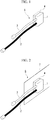
Fig. 1 is a diagram illustrating the minimum structure of a cooling system according to a first embodiment. -
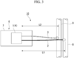
Fig. 2 is a diagram illustrating the minimum structure of a module according to a second embodiment. -
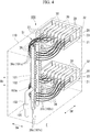
Fig. 3 is a diagram illustrating the minimum structure of a device according to a third embodiment. -
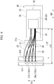
Fig. 4 is a perspective view illustrating the structure of a server device according to a fourth embodiment. -
Fig. 5 is a perspective view illustrating the structure of a server according to the fourth embodiment. -
Fig. 6 is a perspective view illustrating the structure of a module provided inside the server according to the fourth embodiment. -
Fig. 7 is a horizontal section view illustrating the structure of the server device according to the fourth embodiment. -
Fig. 8 is a side section view illustrating the structure of the server device according to the fourth embodiment. - Multiple embodiments of the present invention will be explained below with reference to the drawings. However, regarding the present embodiments, the portions that are identical to the aforementioned conventional example will be referred to by using the same names, and their explanations will be omitted.
-
Fig. 1 is a diagram illustrating the minimum structure of a cooling system according to a first embodiment. - As illustrated in this drawing, it is sufficient for the
cooling system 5 to comprise at least acooling unit 1, asupply connection tube 2 and adischarge connection tube 3. - The
cooling unit 1 cools a heat-generating component 4. - The
supply connection tube 2 is connected to thecooling unit 1. Thesupply connection tube 2 supplies a cooling medium to thecooling unit 1. - The
discharge connection tube 3 is connected to thecooling unit 1. Thedischarge connection tube 3 discharges the cooling medium from thecooling unit 1. - The
supply connection tube 2 and thedischarge connection tube 3 have mutually different lengths. - In this
cooling system 5, thesupply connection tube 2 and thedischarge connection tube 3 have different lengths, so it is possible to easily and reliably distinguish between thesupply connection tube 2 and thedischarge connection tube 3 visually. Thus, it is possible to suppress situations in which thesupply connection tube 2 and thedischarge connection tube 3 are misrecognized and confused with each other. Therefore, in a structure in which thesupply connection tube 2 and thedischarge connection tube 3 can be independently inserted and withdrawn, it is possible to prevent erroneous connections of thesupply connection tube 2 and thedischarge connection tube 3. -
Fig. 2 is a diagram illustrating the minimum structure of a module according to a second embodiment. - As illustrated in this drawing, it is sufficient for the
module 6 to comprise at least asubstrate 7, acooling unit 1, asupply connection tube 2 and adischarge connection tube 3. - A heat-
generating component 4 is mounted on thesubstrate 7. Thecooling unit 1 cools the heat-generating component 4. - The
supply connection tube 2 is connected to thecooling unit 1. Thesupply connection tube 2 supplies a cooling medium to thecooling unit 1. - The
discharge connection tube 3 is connected to thecooling unit 1. Thedischarge connection tube 3 discharges the cooling medium from thecooling unit 1. - The
supply connection tube 2 and thedischarge connection tube 3 have mutually different lengths. - In this
module 6, thesupply connection tube 2 and thedischarge connection tube 3 have different lengths, so thesupply connection tube 2 and thedischarge connection tube 3 can be easily and reliably distinguished visually. Thus, it is possible to suppress situations in which thesupply connection tube 2 and thedischarge connection tube 3 are misrecognized and confused with each other. Therefore, in a structure in which thesupply connection tube 2 and thedischarge connection tube 3 can be independently inserted and withdrawn, it is possible to prevent erroneous connections of thesupply connection tube 2 and thedischarge connection tube 3. - Regarding the above-described first and second embodiments,
Fig. 1 and Fig. 2 illustrate thesupply connection tube 2 as being longer than thedischarge connection tube 3, but there is no such limitation. Thedischarge connection tube 3 may be made longer than thesupply connection tube 2. -
Fig. 3 is a diagram illustrating the minimum structure of a device according to a third embodiment. - As illustrated in this drawing, it is sufficient for the
device 10 to comprise at least amodule 6, asupply tube 8 and adischarge tube 9. - The
module 6 is similar to that indicated in the above-described second embodiment. In other words, themodule 6 comprises at least asubstrate 7, acooling unit 1, asupply connection tube 2 and adischarge connection tube 3. - A heat-
generating component 4 is mounted on thesubstrate 7. Thecooling unit 1 cools the heat-generatingcomponent 4. - The
supply connection tube 2 is connected to thecooling unit 1. Thesupply connection tube 2 supplies a cooling medium to thecooling unit 1. Thedischarge connection tube 3 is connected to thecooling unit 1. Thedischarge connection tube 3 discharges the cooling medium from thecooling unit 1. Thesupply connection tube 2 and thedischarge connection tube 3 have mutually different lengths. - The
supply connection tube 2 is connected to thesupply tube 8. Thedischarge connection tube 3 is connected to thedischarge tube 9. Thesupply tube 8 and thedischarge tube 9 are provided at different positions, so that a distance L1 between the coolingunit 1 and thesupply tube 8, and a distance L2 between the coolingunit 1 and thedischarge tube 9 are different. - In this
device 10, in addition to thesupply connection tube 2 and thedischarge connection tube 3 having different lengths, the distance L1 between the coolingunit 1 and thesupply tube 8 is also different from the distance L2 between the coolingunit 1 and thedischarge tube 9. Thus, in addition to being able to easily and reliably distinguish between thesupply connection tube 2 and thedischarge connection tube 3 visually, it is possible to easily and reliable distinguish between thesupply tube 8 and thedischarge tube 9, to which one of thesupply connection tube 2 and thedischarge connection tube 3 is to be connected. Therefore, it is possible to suppress situations in which thesupply tube 8 and thedischarge tube 9, to which one of thesupply connection tube 2 and thedischarge connection tube 3 is to be connected, are misrecognized and confused with each other. As a result thereof, in a structure in which thesupply connection tube 2 and thedischarge connection tube 3 can be independently inserted and withdrawn, it is possible to prevent erroneous connections of thesupply connection tube 2 and thedischarge connection tube 3. -
Fig. 4 is a perspective view illustrating the structure of a server device according to a fourth embodiment. - As illustrated in
Fig. 4 , the server device (device) 100 in the fourth embodiment comprises arack 110 andservers 20 housed inside therack 110. Theserver device 100 houses a plurality ofservers 20 arranged in the vertical direction inside therack 110. - Each
server 20 has a rectangular parallelepiped-shapedenclosure 21. Theenclosures 21 are supported so as to be able to move in the front-rear direction Df inside therack 110 by means of slide rails (not illustrated). - Inside the
rack 110, asupply tube 101 and adischarge tube 102 are provided to the rear, in the front-rear direction Df, with respect to theenclosures 21 of theservers 20. Thesupply tube 101 and thedischarge tube 102 both extend in the vertical direction Dv. Thesupply tube 101 supplies, for example, cooling water, as a cooling medium, to theserver device 100. Thedischarge tube 102 discharges the cooling water from theserver device 100. - A
water supply tube 103 is connected to thesupply tube 101, thewater supply tube 103 supplying cooling water from the facility in which theserver device 100 is installed. Thewater supply tube 103 rises upward from a floor surface F and atip portion 103a thereof is connected to a middle portion, in the vertical direction Dv, of thesupply tube 101. On thewater supply tube 103, aflow rate sensor 105 is provided between the floor surface F and thetip portion 103a. Theflow rate sensor 105 monitors the flow rate of the cooling water supplied to theserver device 100. - Thus, by connecting the
tip portion 103a of thewater supply tube 103 to the middle portion, in the vertical direction Dv, of thesupply tube 101, theflow rate sensor 105 can be provided between the floor surface F and thetip portion 103a of thewater supply tube 103. Therefore, there is no need to form a hole or the like in the floor surface F in order to install theflow rate sensor 105, and theflow rate sensor 105 can be easily provided while making effective use of the space inside therack 110. -
Fig. 5 is a perspective view illustrating the structure of a server according to the fourth embodiment.Fig. 6 is a perspective view illustrating the structure of a module provided inside the server according to the fourth embodiment.Fig. 7 is a horizontal section view illustrating the structure of the server device according to the fourth embodiment.Fig. 8 is a side section view illustrating the structure of the server device according to the fourth embodiment. - As illustrated in
Fig. 5 , theserver 20 comprises a plurality of electronic components, such asmodules 30, inside theenclosure 21. - As illustrated in
Fig. 5 and6 , amodule 30 comprises asubstrate 32, a coolingunit 33, asupply connection tube 36 and adischarge connection tube 37. - The
substrate 32 is in the shape of a rectangular plate. Thesubstrate 32 is arranged so that, in a state in which themodule 30 is housed within theenclosure 21, a long edge S11 is aligned with the front-rear direction Df and a short edge S12 is aligned with the vertical direction Dv. Thesubstrate 32 is connected, so as to be able to be inserted and withdrawn, to a base substrate (not illustrated) that is arranged along the bottom surface of theenclosure 21. - The
substrate 32 has a heat-generatingcomponent 34 such as a CPU (Central Processing Unit). The heat-generatingcomponent 34 is mounted on onesurface 32f of thesubstrate 32. - A cooling
unit 33 is provided on thesubstrate 32. The coolingunit 33 is provided so as to be stacked on the heat-generatingcomponent 34. The coolingunit 33 cools the heat-generatingcomponent 34. The coolingunit 33 has a prescribed thickness in the direction orthogonal to the onesurface 32f of thesubstrate 32. The coolingunit 33 has arecess 33s on the side facing the heat-generatingcomponent 34. Therecess 33s faces at least a portion of the surface of the heat-generatingcomponent 34. - As illustrated in
Fig. 5 to Fig. 8 , eachsupply connection tube 36 has oneend 36a connected to acooling unit 33. Thesupply connection tube 36 extends to the outside of thesubstrate 32. Thesupply connection tube 36 extends from thesubstrate 32, through therear surface 21b located at the rear, in the front-rear direction Df, of theenclosure 21, and rearward from theenclosure 21. Thesupply connection tube 36 has aconnection elbow 36c on theother end 36b that extends rearward from theenclosure 21. Theconnection elbow 36c is detachably connected to a connection joint 101c formed on thesupply tube 101. - Cooling water is fed to the
supply connection tube 36 through thewater supply tube 103 and thesupply tube 101. Thesupply connection tube 36 supplies cooling water that has been fed from thesupply tube 101 to therecess 33s in thecooling unit 33. - The
discharge connection tube 37 has oneend 37a connected to thecooling unit 33. Thedischarge connection tube 37 extends to the outside of thesubstrate 32. Thedischarge connection tube 37 extends from thesubstrate 32, through therear surface 21b located at the rear, in the front-rear direction Df, of theenclosure 21, and rearward from theenclosure 21. Thedischarge connection tube 37 has aconnection elbow 37c on theother end 37b that extends rearward from theenclosure 21. Theconnection elbow 37c is detachably connected to a connection joint 102c provided on thedischarge tube 102. - The
discharge connection tube 37 discharges cooling water from therecess 33s in thecooling unit 33. The cooling water that is discharged through thedischarge connection tube 37 is discharged to the outside through thedischarge tube 102. - The
discharge connection tube 37 is connected to the discharge tube (not illustrated) that discharges cooling water to the outside. - A
cooling system 31 of themodule 30 is formed by the coolingunit 33, thesupply connection tube 36 and thedischarge connection tube 37 mentioned above. - In this
cooling system 31, thesupply connection tube 36 and thedischarge connection tube 37 have mutually different lengths. In the present embodiment, thesupply connection tube 36 is longer, by a predetermined standard length, than thedischarge connection tube 37 is. - As illustrated in
Fig. 5 andFig. 7 , a plurality ofmodules 30 as mentioned above are housed inside theenclosure 21 of eachserver 20. Inside theenclosure 21, the plurality ofmodules 30 are arranged so as to be spaced in the width direction Dw, which is orthogonal to the front-rear direction Df and the vertical direction Dv. - Thus, the
supply connection tubes 36 and thedischarge connection tubes 37 of a plurality ofmodules 30 extend rearward from therear surface 21b of theenclosure 21 of eachserver 20. The respectivesupply connection tubes 36 that extend from the plurality ofmodules 30 are connected to thesupply tube 101, which is located to the rear inside therack 110. Additionally, thedischarge connection tubes 37 are connected to thedischarge tube 102, which is located to the rear inside therack 110. - In each
server 20, the lengths of thesupply connection tubes 36 are the same for the plurality ofmodules 30. Additionally, the lengths of thedischarge connection tubes 37 are the same for the plurality ofmodules 30. - The
supply tube 101 and thedischarge tube 102 are provided at a central portion, in the width direction Dw, of theenclosure 21. Furthermore, as illustrated inFig 7 andFig 8 , thesupply tube 101 and thedischarge tube 102 are arranged so as to be side-by-side in the front-rear direction Df. In the present embodiment, thesupply tube 101 is provided to the rear, in the front-rear direction Df, relative to thedischarge tube 102. Thus, thesupply tube 101 and thedischarge tube 102 are respectively provided at positions such that the distance L11 between the coolingunits 33 and thesupply tube 101, and the distance L12 between the coolingunits 33 and thedischarge tube 102 are different. In other words, the distance L11 between the coolingunits 33 and thesupply tube 101 is greater than the distance L12 between the coolingunits 33 and thedischarge tube 102. - Thus, the
supply connection tubes 36, which are longer than thedischarge connection tubes 37, are connected to thesupply tube 101, which is at a greater distance L11 from (farther from) thecooling units 33. Additionally, thedischarge connection tubes 37, which are shorter than thesupply connection tubes 36, are connected to thedischarge tube 102, which is at a smaller distance L12 from (closer to) thecooling units 33. - In this case, it is preferable for the
discharge connection tubes 37, which are shorter than thesupply connection tubes 36, to be set to have a length not reaching thesupply tube 101, which is at the greater distance L11 from the coolingunits 33. For example, the lengths of thedischarge connection tubes 37 are lengths such that thedischarge tube 102 can be reached but thesupply tube 101 cannot be reached. - In each
server 20, the plurality ofsupply connection tubes 36 connected to the plurality of coolingunits 33 on the plurality ofmodules 30 have connection positions, on thesupply tube 101, that are different from each other. Thesupply connection tubes 36 connected respectively to the plurality of coolingunits 33 have connection positions, on thesupply tube 101, that are different from each other. Additionally, in eachserver 20, the plurality ofdischarge connection tubes 37 connected to the plurality of coolingunits 33 on the plurality ofmodules 30 have connection positions, on thedischarge tube 102, that are different from each other. Thedischarge connection tubes 37 connected respectively to the plurality of coolingunits 33 have connection positions, on thedischarge tube 102, that are different from each other. - Specifically, the plurality of
supply connection tubes 36 anddischarge connection tubes 37 on theservers 20 respectively have connection positions, on thesupply tube 101 and thedischarge tube 102, that are provided at a plurality of different locations at positions that are different from each other in the circumferential direction. For example, the connection positions, in the circumferential direction, of thesupply connection tubes 36 and thedischarge connection tubes 37 on thesupply tube 101 and thedischarge tube 102, respectively, are provided at a plurality of locations that are different from each other. In the present embodiment, as illustrated inFig. 7 , the plurality ofsupply connection tubes 36 anddischarge connection tubes 37, when viewing their respective connection positions on thesupply tube 101 and thedischarge tube 102 in the vertical direction Dv, are provided at two locations at positions that are different from each other in the circumferential direction. In other words, thesupply tube 101 and thedischarge tube 102 haveconnection joints connection joints - Among the plurality of
supply connection tubes 36 anddischarge connection tubes 37 in eachserver 20, theconnection tube groups supply connection tubes 36 and thedischarge connection tubes 37 that extend rearward from the one side Dw1 in the width direction Dw are respectively connected to the connection joints 101c, 102c that protrude diagonally towards the one side Dw1 in the width direction Dw. Theconnection tube groups supply connection tubes 36 and thedischarge connection tubes 37 that extend rearward from the other side Dw2 in the width direction Dw are respectively connected to the connection joints 101c, 102c that protrude diagonally towards the other side Dw2 in the width direction Dw. - Thus, the
connection tube groups connection tube groups supply connection tubes 36 anddischarge connection tubes 37 are divided into theconnection tube groups connection tube groups - In this way, in accordance with the positions of the
respective modules 30 in the width direction Dw, the other ends 36b, 37b of thesupply connection tubes 36 and thedischarge connection tubes 37 on the sides towards thesupply tube 101 and thedischarge tube 102 can be directed towards the sides on which themodules 30, to which the one ends of the 36a, 37a of thosesupply connection tubes 36 anddischarge connection tubes 37 are to be connected, are positioned. Thus, thesupply connection tubes 36 and thedischarge connection tubes 37 can be routed so as not to apply so much force that thesupply connection tubes 36 and thedischarge connection tubes 37 are excessively bent. In other words, thesupply connection tubes 36 and thedischarge connection tubes 37 can be arranged without excessively bending thesupply connection tubes 36 and thedischarge connection tubes 37. - As illustrated in
Fig. 8 , the plurality ofsupply connection tubes 36 anddischarge connection tubes 37 in eachserver 20 have connection positions, respectively, on thesupply tube 101 and thedischarge tube 102, that are different from each other in the vertical direction Dv. On thesupply tube 101 and thedischarge tube 102, the connection joints 101c, 102c to which the plurality ofsupply connection tubes 36 anddischarge connection tubes 37 of eachserver 20 are respectively connected are provided so as to be spaced in the vertical direction Dv. - In this case, as illustrated in
Fig. 7 , when viewed from the vertical direction Dv, the distances from the coolingunits 33 to thesupply tube 101 and thedischarge tube 102 are different from each other between the plurality ofmodules 30 at different positions in the width direction Dw inside theserver 20. - Therefore, the connection joints 101c, 102c are arranged so that the height differences in the vertical direction Dv relative to the one ends 36a, 37a of the
supply connection tubes 36 and thedischarge connection tubes 37 are small for the connection joints 101c, 102c connected to thesupply connection tubes 36 and thedischarge connection tubes 37 extending from themodules 30 in which the distances from the coolingunits 33 to thesupply tube 101 and thedischarge tube 102 are large. The connection joints 101c, 102c are arranged so that the height differences in the vertical direction Dv relative to the one ends 36a, 37a of thesupply connection tubes 36 and thedischarge connection tubes 37 are large for the connection joints 101c, 102c connected to thesupply connection tubes 36 and thedischarge connection tubes 37 extending from themodules 30 in which the distances from the coolingunits 33 to thesupply tube 101 and thedischarge tube 102 are small. - In the case of the present embodiment, the
supply tube 101 and thedischarge tube 102 are provided in the central portion in the width direction Dw. For this reason, the distances to themodules 30 positioned on the outer sides in the width direction Dw are longer and the distances to themodules 30 positioned on the inner sides in the width direction Dw are shorter. - Therefore, as illustrated in
Fig. 4 andFig. 8 , the height differences in the vertical direction Dv with respect to the one ends 36a, 37a of thesupply connection tubes 36 and thedischarge connection tubes 37 are made smaller for the connection joints 101c, 102c to which thesupply connection tubes 36 and thedischarge connection tubes 37 of themodules 30 positioned on the outer sides in the width direction Dw are connected. For example, thesupply connection tubes 36 and thedischarge connection tubes 37 of themodules 30 that are positioned further on the outer sides are connected toconnection joints - The height differences in the vertical direction Dv with respect to the one ends 36a, 37a of the
supply connection tubes 36 and thedischarge connection tubes 37 are made larger for the connection joints 101c, 102c to which thesupply connection tubes 36 and thedischarge connection tubes 37 of themodules 30 positioned towards the center in the width direction Dw are connected. For example, thesupply connection tubes 36 and thedischarge connection tubes 37 of themodules 30 that are positioned further on the inner sides are connected toconnection joints - Thus, among the
supply connection tubes 36 and discharge connection tubes extending from the plurality ofmodules 30 in eachserver 20, the distances from the one ends 36a, 37a on the sides towards themodules 30 to the other ends 36b, 37b on the sides towards thesupply tube 101 and thedischarge tube 102 are made as uniform as possible. In other words, the lengths of thesupply connection tubes 36 and thedischarge connection tubes 37 can easily be made uniform between the plurality ofmodules 30 having different positions in the width direction Dw. - In this
cooling system 31,modules 30 andserver device 100, the lengths of thesupply connection tubes 36 and thedischarge connection tubes 37 are different. Thus, thesupply connection tubes 36 and thedischarge connection tubes 37 can be easily and reliably distinguished visually. Therefore, it is possible to suppress situations in which thesupply connection tubes 36 and thedischarge connection tubes 37 are misrecognized and thesupply tube 101 and thedischarge tube 102, to which they are to be connected, are confused with each other. As a result thereof, in a structure in which thesupply connection tubes 36 and thedischarge connection tubes 37 can be independently inserted and withdrawn, erroneous connections of thesupply connection tubes 36 and thedischarge connection tubes 37 can be prevented. - In this
server device 100, thesupply tube 101 and thedischarge tube 102 are respectively arranged so that the distance L11 between the coolingunits 33 and thesupply tube 101 and the distance L12 between the coolingunits 33 and thedischarge tube 102 are different. Thus, it is possible to easily and reliably distinguish visually betweensupply connection tubes 36 anddischarge connection tubes 37, as well as to easily and reliably distinguish visually between thesupply tube 101 and thedischarge tube 102 to which thesupply connection tubes 36 or thedischarge connection tubes 37 are to be connected. Thus, it is possible to suppress situations in which thesupply tube 101 and thedischarge tube 102, to which thesupply connection tubes 36 or thedischarge connection tubes 37 are to be connected, are misrecognized and confused with each other. Therefore, in a structure in which thesupply connection tubes 36 and thedischarge connection tubes 37 can be independently inserted and withdrawn, erroneous connections of thesupply connection tubes 36 and thedischarge connection tubes 37 can be prevented. - In this
server device 100, thesupply connection tubes 36 anddischarge connection tubes 37 extending respectively from the plurality ofmodules 30 provided in theenclosure 21 are respectively connected to thesupply tube 101 and thedischarge tube 102. Thus, cooling water that is supplied from thesupply tube 101 can be supplied so as to be distributed, through thesupply connection tubes 36, to thecooling unit 33 in eachmodule 30. Additionally, the cooling water discharged from each coolingunit 33 can be collected, through thedischarge connection tubes 37, in thedischarge tube 102 and discharged. - In this server device, the
supply tube 101 and thedischarge tube 102 are provided in a central portion in the width direction Dw of theenclosure 21. Thus, thesupply connection tubes 36 and thedischarge connection tubes 37 extending from themodules 30 that are arranged so that a plurality are arrayed in the width direction Dw can be collected and connected to thesupply tube 101 and thedischarge tube 102 positioned at the central portion in the width direction Dw. Thus, there is less need to make the lengths of thesupply connection tubes 36 and thedischarge connection tubes 37 different between the plurality ofmodules 30 in comparison to the case in which thesupply tube 101 and thedischarge tube 102 are arranged towards either end in the width direction Dw inside therack 110. Therefore, in the present embodiment, it is possible to make the lengths of thesupply connection tubes 36 and the lengths of thedischarge connection tubes 37 the same between the plurality ofmodules 30 in eachserver 20. As a result thereof, it is possible to standardize the components of thesupply connection tubes 36 and thedischarge connection tubes 37 respectively, thereby suppressing component costs. - In this
server device 100, thesupply tube 101 and thedischarge tube 102 are arranged so as to be side-by-side in the front-rear direction Df. Thus, the distance L11 between the coolingunits 33 and thesupply tube 101, and the distance L12 between the coolingunits 33 and thedischarge tube 102 can be made more reliably different. Therefore, thesupply tube 101 and thedischarge tube 102, to which thesupply connection tubes 36 or thedischarge connection tubes 37 are to be connected, can be easily and reliably distinguished. Thus, it is possible to suppress situations in which thesupply tube 101 and thedischarge tube 102, to which thesupply connection tubes 36 or thedischarge connection tubes 37 are to be connected, are misrecognized and confused with each other. As a result thereof, in a structure in which thesupply connection tubes 36 and thedischarge connection tubes 37 can be independently inserted and withdrawn, erroneous connections of thesupply connection tubes 36 and thedischarge connection tubes 37 can be prevented. - In this
server device 100, the connection positions of the plurality ofsupply connection tubes 36 on thesupply tube 101 are different from each other between the plurality ofmodules 30. Additionally, the connection positions of the plurality ofdischarge connection tubes 37 on thesupply tube 102 are different from each other between the plurality ofmodules 30. The connection positions, respectively, of thesupply connection tubes 36 and thedischarge connection tubes 37 on thesupply tube 101 and thedischarge tube 102 are made easier to distinguish. - In this
server device 100, the connection positions, respectively, of thesupply connection tubes 36 and thedischarge connection tubes 37 on thesupply tube 101 and thedischarge tube 102 are different from each other in the vertical direction Dv between the plurality ofmodules 30. Thus, on thesupply connection tubes 36 and thedischarge connection tubes 37 extending from the plurality of modules in eachserver 20, the distance from the one ends 36a, 37a towards themodules 30 to the other ends 36b, 37b towards thesupply tube 101 and thedischarge tube 102 are made as uniform as possible. Therefore, the lengths of thesupply connection tubes 36 and the lengths of thedischarge connection tubes 37 can be made respectively the same between the plurality ofmodules 30 in eachserver 20. As a result thereof, it becomes possible to standardize the components of thesupply connection tubes 36 and thedischarge connection tubes 37 respectively, thereby suppressing component costs. - In this
server device 100, thesupply connection tubes 36 and thedischarge connection tubes 37 are arranged so that the respective connection positions thereof on thesupply tube 101 and thedischarge tube 102 are at two locations at positions that are different from each other in the circumferential direction. - Thus, in accordance with the positions of the
modules 30 in the width direction Dw, the other ends 36b, 37b of thesupply connection tubes 36 and thedischarge connection tubes 37 on the sides towards thesupply tube 101 and thedischarge tube 102 can be directed towards the sides on which themodules 30, to which the one ends of the 36a, 37a of thosesupply connection tubes 36 anddischarge connection tubes 37 are to be connected, are positioned. Thus, thesupply connection tubes 36 and thedischarge connection tubes 37 can be routed so as not to apply so much force that thesupply connection tubes 36 and thedischarge connection tubes 37 are excessively bent. - Additionally, the
connection tube groups connection tube groups connection tube groups connection tube groups rear surface 21b of theenclosure 21, it becomes possible to easily perform attachment and detachment work, other maintenance work or the like, on wiring and the like positioned in the central portion in the width direction Dw. - Additionally, in the above-described embodiments, the
modules 30 were provided inside theservers 20, but the number installed and the purposes for which they are used are not limited in any way. Additionally, it is possible to house various electronic components other thanmodules 30 inside theserver 20. - Additionally, in the above-described embodiments, the
supply tube 101 and thedischarge tube 102 were provided at the central portion in the width direction Dw, but they may be installed at other positions. Furthermore, thesupply tube 101 and thedischarge tube 102 were provided side-by-side in the front-rear direction Df, but there is no limitation thereto, and other arrangements are possible. - Furthermore, the
flow rate sensor 105 is not limited to being on thewater supply tube 103 and may be provided on thesupply tube 101 or thedischarge tube 102. However, a plurality ofconnection joints supply tube 101 and thedischarge tube 102. For this reason, there are cases in which the installation position of theflow rate sensor 105 is limited. Additionally, on the side with thedischarge tube 102, there are cases in which, for example, bubbles are intermixed with the cooling water due to the attachment or detachment of amodule 30 or the like, so it is preferable to provide theflow rate sensor 105 on thewater supply tube 103 or thesupply tube 101, which are on the upstream side. - Aside therefrom, it is possible to select whether or not to adopt features described in the above-mentioned embodiments, or to appropriately replace some of the features with other features, as long as the invention does not depart from the spirit of the present invention.
- Priority is claimed on Japanese Patent Application No.
2017-203473, filed October 20, 2017 - The cooling system, module, and device of the present invention make it possible to prevent erroneous connections of supply connection tubes and discharge connection tubes in a structure in which the supply connection tubes and the discharge connection tubes can be independently inserted and withdrawn.
-
- 1
- Cooling unit
- 2
- Supply connection tube
- 3
- Discharge connection tube
- 4
- Heat-generating component
- 5
- Cooling system
- 6
- Module
- 7
- Substrate
- 8
- Supply tube
- 9
- Discharge tube
- 10
- Device
- 20
- Server
- 21
- Enclosure
- 30
- Module
- 32
- Substrate
- 33
- Cooling unit
- 34
- Heat-generating component
- 36
- Supply connection tube
- 37
- Discharge connection tube
- 100
- Server device (device)
- 101
- Supply tube
- 102
- Discharge tube
- 110
- Rack
- Df
- Front-rear direction
- Dv
- Vertical direction
- Dw
- Width direction
- LI, L11
- Distance
- L2, L12
- Distance
Claims (9)
- A cooling system comprising:a cooling unit that cools a heat-generating component;a supply connection tube that is connected to the cooling unit and that supplies a cooling medium to the cooling unit; anda discharge connection tube that is connected to the cooling unit and that discharges the cooling medium from the cooling unit,wherein the supply connection tube and the discharge connection tube have different lengths.
- A module comprising:a substrate on which a heat-generating component is provided;a cooling unit that cools the heat-generating component;a supply connection tube that is connected to the cooling unit and that supplies a cooling medium to the cooling unit; anda discharge connection tube that is connected to the cooling unit and that discharges the cooling medium from the cooling unit,wherein the supply connection tube and the discharge connection tube have different lengths.
- A device comprising:the module according to claim 2;a supply tube to which the supply connection tube is connected; anda discharge tube to which the discharge connection tube is connected,wherein the supply tube and the discharge tube are provided at positions such that a distance between the cooling unit and the supply tube and a distance between the cooling unit and the discharge tube are different.
- The device according to claim 3, wherein:a plurality of the modules is housed in a enclosure; andsupply connection tubes and discharge connection tubes connected respectively to a plurality of cooling units on a plurality of the modules are connected respectively to the supply tube and the discharge tube.
- The device according to claim 4, wherein:
the supply tube and the discharge tube are provided at a central portion in a width direction of the enclosure. - The device according to any one of claims 3 to 5, wherein:the supply tube and the discharge tube are respectively arranged so as to extend in a vertical direction; andthe supply tube and the discharge tube are arranged side-by-side in a front-rear direction orthogonal to the vertical direction and to the width direction of the enclosure.
- The device according to any one of claims 3 to 6, wherein:the supply tube and the discharge tube are respectively arranged so as to extend in a vertical direction;supply connection tubes connected respectively to a plurality of cooling units on a plurality of the modules have connection positions, on the supply tube, that are different from each other; anddischarge connection tubes connected respectively to a plurality of cooling units on a plurality of the modules have connection positions, on the discharge tube, that are different from each other.
- The device according to claim 7, wherein:
the connection positions of the supply connection tubes and the discharge connection tubes, respectively, on the supply tube and the discharge tube are different from each other in the vertical direction. - The device according to claim 7 or 8, wherein:
the connection positions of the supply connection tubes and the discharge connection tubes, respectively, on the supply tube and the discharge tube are provided at a plurality of locations at positions that are different from each other in the circumferential direction.
Applications Claiming Priority (2)
| Application Number | Priority Date | Filing Date | Title |
|---|---|---|---|
| JP2017203473A JP6579633B2 (en) | 2017-10-20 | 2017-10-20 | apparatus |
| PCT/JP2018/027740 WO2019077828A1 (en) | 2017-10-20 | 2018-07-24 | Cooling system, module, and device |
Publications (2)
| Publication Number | Publication Date |
|---|---|
| EP3700313A1 true EP3700313A1 (en) | 2020-08-26 |
| EP3700313A4 EP3700313A4 (en) | 2021-07-28 |
Family
ID=66173202
Family Applications (1)
| Application Number | Title | Priority Date | Filing Date |
|---|---|---|---|
| EP18869196.8A Withdrawn EP3700313A4 (en) | 2017-10-20 | 2018-07-24 | COOLING SYSTEM, MODULE AND DEVICE |
Country Status (4)
| Country | Link |
|---|---|
| US (1) | US11470741B2 (en) |
| EP (1) | EP3700313A4 (en) |
| JP (1) | JP6579633B2 (en) |
| WO (1) | WO2019077828A1 (en) |
Cited By (1)
| Publication number | Priority date | Publication date | Assignee | Title |
|---|---|---|---|---|
| EP4340018A4 (en) * | 2021-06-14 | 2025-05-07 | NEC Platforms, Ltd. | COOLING DEVICE |
Family Cites Families (15)
| Publication number | Priority date | Publication date | Assignee | Title |
|---|---|---|---|---|
| JP4199018B2 (en) * | 2003-02-14 | 2008-12-17 | 株式会社日立製作所 | Rack mount server system |
| US7692924B2 (en) | 2008-03-03 | 2010-04-06 | Nabtesco Corporation | Rack for housing a liquid-cooled electric unit |
| US7639499B1 (en) * | 2008-07-07 | 2009-12-29 | International Business Machines Corporation | Liquid cooling apparatus and method for facilitating cooling of an electronics system |
| US20100254758A1 (en) * | 2009-04-06 | 2010-10-07 | International Business Machines Corporation | Apparatus and method for forming a mechanical, fluid-tight connection |
| TWI445289B (en) * | 2011-08-19 | 2014-07-11 | Inventec Corp | Coolant pipe of sever rack |
| US9811127B2 (en) | 2012-11-08 | 2017-11-07 | Hewlett Packard Enterprise Development Lp | Twin server blades for high-density clustered computer system |
| CN104144591A (en) * | 2013-05-09 | 2014-11-12 | 鸿富锦精密工业(深圳)有限公司 | Cooling device and server cabinet with the same |
| US9423058B2 (en) * | 2014-04-07 | 2016-08-23 | International Business Machines Corporation | Formed hose with different fiber-reinforced regions |
| JP6604330B2 (en) * | 2014-09-26 | 2019-11-13 | 日本電気株式会社 | Refrigerant relay device, cooling device using the same, and cooling method |
| GB201513415D0 (en) * | 2015-07-30 | 2015-09-16 | Senior Uk Ltd | Finned coaxial cooler |
| JP6170110B2 (en) * | 2015-10-15 | 2017-07-26 | Necプラットフォームズ株式会社 | Cooling device and refrigerant relay device |
| JP6034465B1 (en) * | 2015-10-15 | 2016-11-30 | Necプラットフォームズ株式会社 | Cooling device and cooling system |
| CN105704989B (en) | 2016-04-26 | 2018-09-28 | 广东申菱环境系统股份有限公司 | Server cabinet with liquid cooling system |
| JP2017203473A (en) | 2016-05-09 | 2017-11-16 | 豊生ブレーキ工業株式会社 | Female screw member |
| JP2018074100A (en) * | 2016-11-04 | 2018-05-10 | 富士通株式会社 | Rack-mount information processing equipment |
-
2017
- 2017-10-20 JP JP2017203473A patent/JP6579633B2/en active Active
-
2018
- 2018-07-24 EP EP18869196.8A patent/EP3700313A4/en not_active Withdrawn
- 2018-07-24 US US16/756,753 patent/US11470741B2/en active Active
- 2018-07-24 WO PCT/JP2018/027740 patent/WO2019077828A1/en not_active Ceased
Cited By (1)
| Publication number | Priority date | Publication date | Assignee | Title |
|---|---|---|---|---|
| EP4340018A4 (en) * | 2021-06-14 | 2025-05-07 | NEC Platforms, Ltd. | COOLING DEVICE |
Also Published As
| Publication number | Publication date |
|---|---|
| US20210195796A1 (en) | 2021-06-24 |
| EP3700313A4 (en) | 2021-07-28 |
| JP6579633B2 (en) | 2019-09-25 |
| WO2019077828A1 (en) | 2019-04-25 |
| JP2019079851A (en) | 2019-05-23 |
| US11470741B2 (en) | 2022-10-11 |
Similar Documents
| Publication | Publication Date | Title |
|---|---|---|
| US10257955B2 (en) | Cable backplane system having individually removable cable connector assemblies | |
| CN107454794B (en) | Thermal Spreader for Cage Electrical Connector Assemblies | |
| US11171443B2 (en) | Connector system with thermal cooling | |
| CN101718898B (en) | Telecommunications patching system with vertically-oriented patching modules | |
| US9099826B2 (en) | Electrical bridge | |
| EP3699730A1 (en) | Device | |
| EP3302014B1 (en) | Server rack system and bidirectional power inlet | |
| US20150181760A1 (en) | Axially aligned electronic chassis | |
| EP3699957A1 (en) | Module, and server | |
| US20220115844A1 (en) | Network element equipment shelf with configurable power location | |
| KR100910859B1 (en) | Interface enhancement for modular platform applications | |
| US12082371B2 (en) | Electronic device | |
| US11470741B2 (en) | Cooling system, module, and device | |
| CN102893194A (en) | System comprising a plurality of distribution devices and distribution device | |
| ITUD20130151A1 (en) | MODULAR SUPERCALCULAR ARCHITECTURE | |
| JP7156706B2 (en) | Cooling system, electronics | |
| US10559904B1 (en) | Link module for a scalable multiprocessor system | |
| US20130294035A1 (en) | Device for Accommodating Mounting Rail Module Cases | |
| WO2014039924A1 (en) | Reducing crosstalk in board-to-board electronic communication | |
| CN217643937U (en) | Functional module and network equipment | |
| US6519145B1 (en) | ETSI/NEBS housing structure | |
| US9253916B2 (en) | Cable backplane system having a cable tray guide and support system | |
| CN205487161U (en) | Display screen box and have its display screen | |
| US9078375B1 (en) | Hardware plane providing improved cooling air flow | |
| US11963337B2 (en) | Contactless device and chip thermal management plate |
Legal Events
| Date | Code | Title | Description |
|---|---|---|---|
| STAA | Information on the status of an ep patent application or granted ep patent |
Free format text: STATUS: THE INTERNATIONAL PUBLICATION HAS BEEN MADE |
|
| PUAI | Public reference made under article 153(3) epc to a published international application that has entered the european phase |
Free format text: ORIGINAL CODE: 0009012 |
|
| STAA | Information on the status of an ep patent application or granted ep patent |
Free format text: STATUS: REQUEST FOR EXAMINATION WAS MADE |
|
| 17P | Request for examination filed |
Effective date: 20200515 |
|
| AK | Designated contracting states |
Kind code of ref document: A1 Designated state(s): AL AT BE BG CH CY CZ DE DK EE ES FI FR GB GR HR HU IE IS IT LI LT LU LV MC MK MT NL NO PL PT RO RS SE SI SK SM TR |
|
| AX | Request for extension of the european patent |
Extension state: BA ME |
|
| DAV | Request for validation of the european patent (deleted) | ||
| DAX | Request for extension of the european patent (deleted) | ||
| A4 | Supplementary search report drawn up and despatched |
Effective date: 20210628 |
|
| RIC1 | Information provided on ipc code assigned before grant |
Ipc: H05K 7/20 20060101AFI20210622BHEP Ipc: G06F 1/20 20060101ALI20210622BHEP Ipc: H01L 23/473 20060101ALI20210622BHEP |
|
| GRAP | Despatch of communication of intention to grant a patent |
Free format text: ORIGINAL CODE: EPIDOSNIGR1 |
|
| STAA | Information on the status of an ep patent application or granted ep patent |
Free format text: STATUS: GRANT OF PATENT IS INTENDED |
|
| INTG | Intention to grant announced |
Effective date: 20230426 |
|
| STAA | Information on the status of an ep patent application or granted ep patent |
Free format text: STATUS: THE APPLICATION IS DEEMED TO BE WITHDRAWN |
|
| 18D | Application deemed to be withdrawn |
Effective date: 20230907 |