EP3700189A1 - Mobile phone vertical capture mode - Google Patents
Mobile phone vertical capture mode Download PDFInfo
- Publication number
- EP3700189A1 EP3700189A1 EP19158422.6A EP19158422A EP3700189A1 EP 3700189 A1 EP3700189 A1 EP 3700189A1 EP 19158422 A EP19158422 A EP 19158422A EP 3700189 A1 EP3700189 A1 EP 3700189A1
- Authority
- EP
- European Patent Office
- Prior art keywords
- mobile device
- image
- boundary
- camera
- points
- Prior art date
- Legal status (The legal status is an assumption and is not a legal conclusion. Google has not performed a legal analysis and makes no representation as to the accuracy of the status listed.)
- Granted
Links
Images


Classifications
-
- G—PHYSICS
- G06—COMPUTING OR CALCULATING; COUNTING
- G06F—ELECTRIC DIGITAL DATA PROCESSING
- G06F3/00—Input arrangements for transferring data to be processed into a form capable of being handled by the computer; Output arrangements for transferring data from processing unit to output unit, e.g. interface arrangements
- G06F3/01—Input arrangements or combined input and output arrangements for interaction between user and computer
- G06F3/03—Arrangements for converting the position or the displacement of a member into a coded form
- G06F3/0304—Detection arrangements using opto-electronic means
-
- G—PHYSICS
- G06—COMPUTING OR CALCULATING; COUNTING
- G06F—ELECTRIC DIGITAL DATA PROCESSING
- G06F1/00—Details not covered by groups G06F3/00 - G06F13/00 and G06F21/00
- G06F1/16—Constructional details or arrangements
- G06F1/1613—Constructional details or arrangements for portable computers
- G06F1/1633—Constructional details or arrangements of portable computers not specific to the type of enclosures covered by groups G06F1/1615 - G06F1/1626
- G06F1/1684—Constructional details or arrangements related to integrated I/O peripherals not covered by groups G06F1/1635 - G06F1/1675
- G06F1/1686—Constructional details or arrangements related to integrated I/O peripherals not covered by groups G06F1/1635 - G06F1/1675 the I/O peripheral being an integrated camera
-
- G—PHYSICS
- G06—COMPUTING OR CALCULATING; COUNTING
- G06F—ELECTRIC DIGITAL DATA PROCESSING
- G06F1/00—Details not covered by groups G06F3/00 - G06F13/00 and G06F21/00
- G06F1/16—Constructional details or arrangements
- G06F1/1613—Constructional details or arrangements for portable computers
- G06F1/1633—Constructional details or arrangements of portable computers not specific to the type of enclosures covered by groups G06F1/1615 - G06F1/1626
- G06F1/1684—Constructional details or arrangements related to integrated I/O peripherals not covered by groups G06F1/1635 - G06F1/1675
- G06F1/1694—Constructional details or arrangements related to integrated I/O peripherals not covered by groups G06F1/1635 - G06F1/1675 the I/O peripheral being a single or a set of motion sensors for pointer control or gesture input obtained by sensing movements of the portable computer
-
- G—PHYSICS
- G06—COMPUTING OR CALCULATING; COUNTING
- G06T—IMAGE DATA PROCESSING OR GENERATION, IN GENERAL
- G06T7/00—Image analysis
- G06T7/10—Segmentation; Edge detection
- G06T7/12—Edge-based segmentation
-
- G—PHYSICS
- G06—COMPUTING OR CALCULATING; COUNTING
- G06T—IMAGE DATA PROCESSING OR GENERATION, IN GENERAL
- G06T7/00—Image analysis
- G06T7/70—Determining position or orientation of objects or cameras
- G06T7/73—Determining position or orientation of objects or cameras using feature-based methods
-
- G—PHYSICS
- G06—COMPUTING OR CALCULATING; COUNTING
- G06V—IMAGE OR VIDEO RECOGNITION OR UNDERSTANDING
- G06V20/00—Scenes; Scene-specific elements
- G06V20/20—Scenes; Scene-specific elements in augmented reality scenes
-
- H—ELECTRICITY
- H04—ELECTRIC COMMUNICATION TECHNIQUE
- H04N—PICTORIAL COMMUNICATION, e.g. TELEVISION
- H04N23/00—Cameras or camera modules comprising electronic image sensors; Control thereof
- H04N23/60—Control of cameras or camera modules
- H04N23/61—Control of cameras or camera modules based on recognised objects
-
- H—ELECTRICITY
- H04—ELECTRIC COMMUNICATION TECHNIQUE
- H04N—PICTORIAL COMMUNICATION, e.g. TELEVISION
- H04N23/00—Cameras or camera modules comprising electronic image sensors; Control thereof
- H04N23/60—Control of cameras or camera modules
- H04N23/62—Control of parameters via user interfaces
-
- H—ELECTRICITY
- H04—ELECTRIC COMMUNICATION TECHNIQUE
- H04N—PICTORIAL COMMUNICATION, e.g. TELEVISION
- H04N23/00—Cameras or camera modules comprising electronic image sensors; Control thereof
- H04N23/60—Control of cameras or camera modules
- H04N23/63—Control of cameras or camera modules by using electronic viewfinders
-
- H—ELECTRICITY
- H04—ELECTRIC COMMUNICATION TECHNIQUE
- H04N—PICTORIAL COMMUNICATION, e.g. TELEVISION
- H04N23/00—Cameras or camera modules comprising electronic image sensors; Control thereof
- H04N23/60—Control of cameras or camera modules
- H04N23/64—Computer-aided capture of images, e.g. transfer from script file into camera, check of taken image quality, advice or proposal for image composition or decision on when to take image
-
- H—ELECTRICITY
- H04—ELECTRIC COMMUNICATION TECHNIQUE
- H04N—PICTORIAL COMMUNICATION, e.g. TELEVISION
- H04N23/00—Cameras or camera modules comprising electronic image sensors; Control thereof
- H04N23/60—Control of cameras or camera modules
- H04N23/667—Camera operation mode switching, e.g. between still and video, sport and normal or high- and low-resolution modes
-
- H—ELECTRICITY
- H04—ELECTRIC COMMUNICATION TECHNIQUE
- H04N—PICTORIAL COMMUNICATION, e.g. TELEVISION
- H04N23/00—Cameras or camera modules comprising electronic image sensors; Control thereof
- H04N23/60—Control of cameras or camera modules
- H04N23/698—Control of cameras or camera modules for achieving an enlarged field of view, e.g. panoramic image capture
Definitions
- the invention relates to mobile device for automatically capturing an image of an object and a method for automatically capturing an image of an object, when the camera of the mobile device is not held at eye level.
- a mobile device for automatically capturing an image of an object comprising:
- Feature b) can comprise to display on the touchscreen an image of an object captured by the camera of the mobile device ; receive at the mobile device by a user input the instruction to label a feature of the object indicating a point on the boundary of the object; determine a point of a boundary of the object.
- the mobile device can further comprise at least one indicator configured to provide a haptic, acoustic or optical signal; the processor can be further configured to determine that the captured image does not comprise all four points, indicate by an activated indicator that the mobile device needs to be moved into the direction of the activated indicator.
- the mobile device can comprise four indicators and at each of the four corners of the mobile device one of the indicators can be positioned.
- the mobile device can comprise four indicators and at each of the four edges between the corners of the mobile device one of the indicators can be positioned.
- the indicators can be vibrators.
- the indicators can be lights.
- the indicator can be a loudspeaker and the processor can be configured to output predefined messages by one or more speakers indicating the direction into which the device needs to be moved.
- the processor can be further configured to indicate that the mobile device is ready to capture an image.
- a method for automatically capturing an image of an object on a mobile device comprising:
- Step cb) can comprise to perform corner detection, blob detection, edge detection or thresholding to determine a determine a point of a boundary of the object.
- Step cb) can comprise displaying on the touchscreen an image of an object captured by the camera of the mobile device ; receiving at the mobile device by a user input the instruction to label a feature of the object indicating a point on the boundary of the object; determining a point of a boundary of the object.
- the method can further comprise between step d) and step e) the step of determining that the captured image does not comprise all four points, indicating by an activated indicator providing a haptic, acoustic or optical signal that the mobile device needs to be moved into the direction of the activated indicator.
- the method can comprise indicating that the mobile device is ready to capture an image, capturing an image and storing the image in a memory of the device.
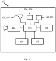
- the device 100 can comprise a camera 102, a memory 103, a gyroscope 105, a touchscreen 104, and at least one indicator 106 configured to provide a haptic, acoustic or optical signal.
- Each of the camera 102, memory 103, gyroscope 105, touchscreen 104, and the at least one indicator 106 configured to provide a haptic, acoustic or optical signal is functionally linked to a processor 101 of the device 100.
- the mobile device 100 includes but is not limited to a smart phone, a touch screen communication device 100, a touch screen information processing system, a touch screen enabled portable communication device 100 and similar devices 100.
- the device 100 contains at least one camera 102 on the back side of the mobile device 100, i.e. on the side of the mobile device 100 opposite to the front side comprising the touchscreen 104.
- the device 100 can also alternatively or in addition contain at least one camera 102 on the front side of the device 100.
- the back side can also comprise two or more cameras 102 and the front side may also comprise at least two or more cameras 102.
- the front side and the back side of the device 100 are connected by two opposing sides, the two lateral sides and the top and the bottom side, wherein the lateral sides are longer than the top and the bottom side. Each side is confined by four edges and an area extending between the edges. The meeting edges form corners.
- Touchscreens 104 like those disclosed herein usually consist of two functional elements.
- the first functional element provides the actual optical display, e.g. liquid crystal display, LCD, or organic light-emitting diode, OLED, display.
- the second functional element provides elements for sensing a touch.
- the mobile device 100 also comprises a transmitter and/or receiver for transmitting/receiving radio waves (WIFI, Bluetooth, radio network like GSM, LTE or evolved LTE or any successors of these standards).
- the gyroscope 105 or any other sensor capable of determining a position of the device 100 in three-dimensional space is capable of determining the relative position of the mobile device 100 in three-dimensional space.
- the gyroscope 105 or any similar sensor is capable of determining whether the back side (or also alternatively the front side) of the device 100 is positioned parallel to the surface of the ground.
- the at least one indicator 106 is configured to provide a haptic, acoustic or optical signal.
- An indicator 106 for providing a haptic signal can be a mechanical vibrator 107, i.e. a small electric motor connected to an off-center weight which are commonly used in mobile devices 100 to provide a vibrating alert.
- An indicator 106 for providing an acoustic signal can be a speaker 108, i.e. a loudspeaker.
- An indicator 106 for providing an optical signal can be a light 109, for example, a light emitting device 100, LED, light.
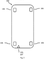
- Figure 2 illustrates possible positions of the indicators 106 in the smartphone.
- the indicators 106 can be positioned in the corners of the device 100.
- the optical indicators 106, 109 are positioned so that they are visible on the surface of the device 100.
- the optical indicators 106, 109 may also be positioned exclusively on the back side or the front side of the smartphone, as illustrated in figure 2 , or may be positioned within the lateral sides and the top/bottom sides, i.e. are visible in the lateral sides and top/bottom side, and the front or back side of the smartphone (not illustrated).
- This has the advantage that the optical indicators 106 are visible to the user independent of how the device 100 is held by the user because the indicators 109 extend from the front side over the lateral sides and the top/bottom side to the back side.
- the optical indicators 109 are visible to the user independent thereof whether the front side or the back side faces the user.
- the haptic indicators 106 may be placed in the same positions at the optical indicators 106 within the device 100, but do not need to be visible to the user.
- a possible position of the speaker in the device 100 is illustrated in figure 2 .
- the position of the speaker within the device 100 is not essential as long as the speaker is positioned in a way that the acoustic signal is hearable to the user.
- the acoustic indicators 106 may be placed in the same positions at the optical or haptic indicators 106. This can provide the advantage that an acoustic message from the device 100 is provided from a specific origin within the smartphone which can be used to forward directional information to the user.
- Figure 3 illustrates alternative possible positions of the indicators 106 on the back side or front side of the smartphone.
- the indicators 106 can be positioned in an area between the corners of the front or back side, preferably in the area close or at the center between two respective corners.
- explanations provided in relation to figure 2 which apply analogously to indicators 106 positioned in an area between the corners of the device 100.
- the mobile device 100 can automatically capture an image.
- a user may attempt to capture a large object by raising the mobile device to a certain distance or height from the large object. This distance or height may be above the eye level of the user and thus the user cannot see on the display (e.g. touchscreen) of the device whether the camera of the device has been positioned such that the device can capture the entire object.
- This distance or height may be above the eye level of the user and thus the user cannot see on the display (e.g. touchscreen) of the device whether the camera of the device has been positioned such that the device can capture the entire object.
- figure 4 illustrates an image captured by the user wherein the captured image does not include the right side of a large object, in this case a table 200 captured from above which contains printed paper on the bottom left side and an incompletely captured power socket on the right top side of the table 200.
- Figure 5 illustrates an image captured by the user wherein the captured image does not include the left side of the table 200 of figure 4 .
- the image now contains printed paper on the bottom left side only incompletely, but the power socket on the right top side of the table 200 is completely captured. The present disclosure avoids this outcome.
- the processor 101 is configured to receive by a user input an instruction to start a mode for automatically capturing an image of an object by a camera 102 of the mobile device 100.
- the user input can be a touching of the user of a particular icon or menu item on the mobile device 100.
- the mode maybe started by a voice command.
- the mode is a specific software program capable of performing the method of the disclosure and being executed by the processor 101 of the mobile device 100.
- the processor 101 In response to the input by the user the processor 101 is configured to start at the mobile device 100 the mode for automatically capturing an image.
- the processor 101 is further configured to determine the boundaries of the object.
- the processor 101 is configured to capture an image of the object in response to a user input and determine a first point of the boundary of the object.
- the determined points are corners of an object, and the points define a boundary around (surrounding) the object. This step is repeated until the processor 101 has determined four points which indicate the boundaries of the object.
- the processor 101 is configured to capture a first image of the object in response to a user input, i.e. a part of the object which is the upper left corner of the table 200 of figures 4 and 5 and as illustrated in figure 6b determines a first point of the boundary of the object, a corner of the object.
- the processor 101 is configured to capture a second image of the object in response to a user input, i.e. a part of the object which is the upper right corner of the table 200 of figures 4 and 5 and as illustrated in figure 7b determines a second point of the boundary of the object, a corner of the object.
- the processor 101 is configured to capture a third image of the object in response to a user input, i.e. a part of the object which is the lower left corner of the table 200 of figures 4 and 5 and as illustrated in figure 8b determines a third point of the boundary of the object, a corner of the object.
- the processor 101 is configured to capture a fourth image of the object in response to a user input, i.e. a part of the object which is the lower right corner of the table 200 of figures 4 and 5 and as illustrated in figure 9b determines a first point of the boundary of the object, a corner of the object.
- This step can be implemented by using known methods in the field of augmented reality.
- interest points, fiducial markers in the captured image are detected by methods like corner detection, blob detection, edge detection or thresholding, and other image processing methods in first state.
- a second stage a real world coordinate system from the data obtained in the first stage is obtained.
- some known methods assume objects with known geometry (or fiducial markers) are present in the scene.
- SLAM simultaneous localization and mapping
- structure from motion methods like bundle adjustment can be used.
- Mathematical methods which can be used in the second stage include projective (epipolar) geometry, geometric algebra, rotation representation with exponential map, kalman and particle filters, nonlinear optimization, robust statistics.
- the processor 101 may map the determined points into the same absolute or relative coordinate system.
- the processor 101 is further configured to determine by an input of the gyroscope 105 that the mobile device 100 is in a substantially horizontal or horizontal position and determine that at least one of the cameras 102 is facing downwards.
- the processor 101 is further configured to determine that the captured image comprises all four points, capture an image, and store the image in a memory 103 of the device 100.
- FIG. 10 the processor 101 first determines that all four points are now present in the image to be captured by the camera 102 (indicated by the star labels). Subsequently, the processor 101 captures the entire object as illustrated in figure 11 .
- the configuration for determining the points in the boundaries of the object comprises that the processor 101 is configured to receive at the mobile device 100 by a user input the instruction to label a feature of the object indicating a point on the boundary of the object.
- the user input can be a touch of the user on the touchscreen 104 display indicating a specific feature of the object. This step is repeated until the processor 101 has determined four points which indicate the boundaries of the object.
- the processor 101 maybe configured to project the position indicated by the user on the touchscreen 104 to a feature of the object using known techniques of augmented reality. This can be followed by the second stage providing a real world coordinate system as explained above. This variation of the mode may be initiated by the user via the selection of a further menu item.
- figures 12 and 13 illustrate the capturing of an object that may have boundaries that may be difficult to identify by an augmented reality algorithm.
- the procedure is similar to the procedures illustrated in figures 6a to 9b , however, for conciseness the consecutive capturing of the four images has been omitted.
- figure 12 illustrates the object after the user has consecutively input four labels indicating the points identifying the boundary of the object (corresponding to figure 10 ).
- the processor 101 can capture an image of the entire object as illustrated in figure 13 .
- This aspect provides the advantage that even when the object does not have any boundaries clearly identifiable by the processor 101 or the processor 101 cannot perform this determination in a rapid manner by, for example, boundary detection the user can input the points of the boundaries directly.
- the processor 101 can also be configured to output a particular signal indicating that the processor 101 is now ready to capture the image, e.g. an acoustic, haptic, or optical signal, and will capture the image within a preset time from the output of the signal. This has the advantage that the user can prepare for the capturing, e.g. by not moving the mobile device 100.
- the processor 101 is configured to determine that the captured image does not comprise all four points, indicate by an activated indicator 106 that the mobile device 100 needs to be moved into the direction indicated the activated indicator 106. This feature had the advantage that the user is informed by the device whether the device needs to be further moved to capture the object in its entirety.
- the processor 101 can be configured to output particular directing messages like "left”, “right”, “closer”, “less close” assisting the user in positioning the device 100 at the correct position with respect to the object. This has the advantage that the user does not need to look at the device 100 while positioning the device 100.
- the device 100 may also contain four different speakers at the corners or between the corners of a side of the device 100 which may provide additional spatial information for positioning the device 100.
- optical or haptic indicators 107, 109 the activation or deactivation of these indicators 106 may indicate the direction into which the mobile device 100 needs to be moved.
- activated indicators 107, 109 permanently lightened of flashing lights or vibrating vibrators
- an indicator 109 lightened up or flashing on a right edge of the device 100 may indicate that the camera 102 is not yet in a position to capture a point on the right boundary of the object.
- the indicators 106 remain activated with respect to the four points on the boundaries of the object when their respective points cannot yet be captured by the camera 102, and are deactivated as soon as their respective points can be captured by the camera 102.
- the following method for automatically capturing an image of an object on a mobile device 100 comprising: receiving S1 at the mobile device 100 by a user input the instruction to start a mode for automatically capturing an image of an object by a camera 102 of the mobile device 100; starting S2 at the mobile device 100 the mode for automatically capturing an image; determining S3 by the mobile device 100 the boundaries of the object, the determining comprising: capturing, by the camera 102, an image of the object in response to a user input; determining a point of a boundary of the object; repeating said steps until four points defining the boundary are determined; determining S4 by the mobile device 100 that the mobile device 100 is in a substantially horizontal position and the camera 102 is facing downwards; when the mobile device 100 determines that the captured image comprises all four points capturing S5 an image and storing the image in a memory 103 of the device 100.
- the method is preferentially performed using the mobile device 100 described above.
- the method may comprise performing corner detection, blob detection, edge detection or thresholding to determine a determine a point of a boundary of the object.
- the method may comprise displaying on the touchscreen 104 an image of an object captured by the camera 102 of the mobile device 100; receiving at the mobile device 100 by a user input the instruction to label a feature of the object indicating a point on the boundary of the object; determining a point of a boundary of the object.
- the method may further comprise the step of determining that the captured image does not comprise all four points, indicating by an activated indicator 106 providing a haptic, acoustic or optical signal that the mobile device 100 needs to be moved into the direction of the activated indicator 106.
- the method may comprise, when the mobile device 100 determines that the captured image comprises all four points, indicating that the mobile device 100 is ready to capture an image, capturing an image and storing the image in a memory 103 of the device 100.
- the method may comprise determining that the captured image does not comprise all four points, indicating by the mobile device 100 by an activated indicator 106 that that the mobile device 100 needs to be moved into the direction of the activated indicator 106.
- the method may comprise that the mobile device 100 comprises four indicators 106 and that at each of the four corners of the mobile device 100 one of the indicators 106 is positioned.
- the method may comprise that the mobile device 100 comprises four indicators 106 and that at each of the four sides of the mobile device 100 one of the indicators 106 is positioned.
- the method may comprise that the indicators 106 are vibrators and the activated indicator 106 is a vibrating vibrator and a deactivated vibrator is a non-vibrating vibrator.
- the method may comprise that the indicators 106 are lights and the activated indicator 106 is a permanently powered light or a flashing light and deactivated indicator 106 is an unpowered light.
- the method may comprise that the step of indicating by an activated indicator 106 is performed by indicating by predefined messages output by one or more speakers comprised in the mobile device 100.
- the method may comprise that indicating by the mobile that the mobile device 100 is ready to capture an image comprises: deactivating the indicators 106 and indicating by a predefined message output by one or more speakers comprised in the mobile device 100 outputting that the device 100 is ready to capture an image.
- a mobile device 100 for automatically capturing an image of an object and a method for automatically capturing an image of an object, when the camera 102 of the mobile device 100 is not held at eye level.
Landscapes
- Engineering & Computer Science (AREA)
- Theoretical Computer Science (AREA)
- Multimedia (AREA)
- General Physics & Mathematics (AREA)
- Signal Processing (AREA)
- Physics & Mathematics (AREA)
- Computer Hardware Design (AREA)
- General Engineering & Computer Science (AREA)
- Human Computer Interaction (AREA)
- Computer Vision & Pattern Recognition (AREA)
- Studio Devices (AREA)
- Telephone Function (AREA)
- User Interface Of Digital Computer (AREA)
Abstract
Description
- The invention relates to mobile device for automatically capturing an image of an object and a method for automatically capturing an image of an object, when the camera of the mobile device is not held at eye level.
- Although applicable to any device comprising a digital camera, the present invention will mainly be described in conjunction with a mobile device comprising a digital camera.
- When taking a picture with a mobile device of a large object on the ground it is often required to position the smartphone at an enlarged distance from the objection because mobile devices usually do not have means like fish-eye optics allowing to take a picture of the complete object from a short distance. Thus, it is required to position the mobile device at an elevated position above the head of the user where the user can no longer see the display showing a preview of the picture to be taken. As a result, the user before triggering the shooting of an image cannot control whether the mobile device is positioned in a way that the entire objected is captured by the camera.
- Accordingly, there is a need for an improved mode to be executed on a mobile device.
- The above stated problem is solved by the features of the independent claims. It is understood, that independent claims of a claim category may be formed in analogy to the dependent claims of another claim category.
- Accordingly, it is provided:
A mobile device for automatically capturing an image of an object comprising: - a camera ;
- a processor;
- a memory ;
- a gyroscope ;
- a touchscreen ;
- wherein the processor is configured to
- receive by a user input the instruction to start a mode for automatically capturing an image of an object by a camera of the mobile device ;
- to start at the mobile device the mode for automatically capturing an image;
- determine the boundaries of the object by being configured to:
- a) capture by the camera an image of the object in response to a user input;
- b) determine a point of a boundary of the object;
- c) repeat steps a) to b) until four points defining a boundary around the object are determined;
- determine by an input of the gyroscope that the mobile device is in a substantially horizontal position and determine that the camera is facing downwards;
- determine that the captured image comprises all four points (201, 202, 203, 204), capture an image, and store the image in the memory of the device
- Feature b) can comprise to display on the touchscreen an image of an object captured by the camera of the mobile device ;
receive at the mobile device by a user input the instruction to label a feature of the object indicating a point on the boundary of the object;
determine a point of a boundary of the object. - The mobile device can further comprise at least one indicator configured to provide a haptic, acoustic or optical signal; the processor can be further configured to determine that the captured image does not comprise all four points, indicate by an activated indicator that the mobile device needs to be moved into the direction of the activated indicator.
- The mobile device can comprise four indicators and at each of the four corners of the mobile device one of the indicators can be positioned.
The mobile device can comprise four indicators and at each of the four edges between the corners of the mobile device one of the indicators can be positioned. - The indicators can be vibrators.
- The indicators can be lights.
- The indicator can be a loudspeaker and the processor can be configured to output predefined messages by one or more speakers indicating the direction into which the device needs to be moved.
- The processor can be further configured to indicate that the mobile device is ready to capture an image.
- Further, it is provided:
A method for automatically capturing an image of an object on a mobile device comprising: - a) Receiving at the mobile device by a user input the instruction to start a mode for automatically capturing an image of an object by a camera of the mobile device ;
- b) Starting at the mobile device the mode for automatically capturing an image;
- c) Determining by the mobile device the boundaries of the object, the determining comprising:
- ca) capturing, by the camera, an image of the object in response to a user input;
- cb) determining a point of a boundary of the object;
- cc) repeat steps ca) to cb) until four points defining a boundary around the object are determined;
- d) Determining by the mobile device that the mobile device is in a substantially horizontal position and the camera is facing downwards;
- e) when the mobile device determines that the captured image comprises all four points capturing an image and storing the image in a memory of the device.
- Step cb) can comprise to perform corner detection, blob detection, edge detection or thresholding to determine a determine a point of a boundary of the object.
- Step cb) can comprise displaying on the touchscreen an image of an object captured by the camera of the mobile device ;
receiving at the mobile device by a user input the instruction to label a feature of the object indicating a point on the boundary of the object;
determining a point of a boundary of the object. - The method can further comprise between step d) and step e) the step of determining that the captured image does not comprise all four points, indicating by an activated indicator providing a haptic, acoustic or optical signal that the mobile device needs to be moved into the direction of the activated indicator.
- When the mobile device determines that the captured image comprises all four points the method can comprise indicating that the mobile device is ready to capture an image, capturing an image and storing the image in a memory of the device.
- Further embodiments of the present invention are subject of the further subclaims and of the following description, referring to the drawings.
- For a more complete understanding of the present invention and advantages thereof, reference is now made to the following description taken in conjunction with the accompanying drawings. The invention is explained in more detail below using exemplary embodiments which are specified in the schematic figures of the drawings, in which:
-
Fig. 1 illustrates amobile device 100 of the present disclosure. -
Fig. 2 illustrates the backside of amobile device 100 of the presentdisclosure comprising indicators 106. -
Fig. 3 illustrates an alternative back side of amobile device 100 of the presentdisclosure comprising indicators 106. -
Fig. 4 and 5 illustrates captured images of objects, which were not captured using thedevice 100 or the method of the present disclosure. -
Fig. 6a, 7a, 8a, 9a illustrate captured images of an object, wherein each image only captured a part of the object. -
Fig. 6b, 7b, 8b, 9b illustrate captured images of an object, wherein each image only captured a part of the object and containing labels indicating a point on a boundary of the object. The points have been obtained augmented reality algorithms. -
Fig. 10 illustrates the image to be captured by thecamera 102 when all points indicating the boundaries of the object are present in the image. -
Fig. 11 illustrates the captured image of the object ofFig. 10 . -
Fig. 12 illustrates an image to be captured by thecamera 102 when all points indicating the boundaries of the object are present in the image and which have been obtained by a user input. -
Fig. 13 illustrates the captured image of the object ofFig. 12 . -
Fig. 14 illustrates a method according to the present disclosure. - In the figures like reference signs denote like elements unless stated otherwise.
- Although specific embodiments have been illustrated and described herein, it will be appreciated by those of ordinary skill in the art that a variety of alternate and/or equivalent implementations exist. It should be appreciated that the exemplary embodiment or exemplary embodiments are only examples, and are not intended to limit the scope, applicability, or configuration in any way. Rather, the foregoing summary and detailed description will provide those skilled in the art with a convenient road map for implementing at least one exemplary embodiment, it being understood that various changes may be made in the function and arrangement of elements described in an exemplary embodiment without departing from the scope as set forth in the appended claims and their legal equivalents. Generally, this application is intended to cover any adaptations or variations of the specific embodiments discussed herein.
- Disclosed is a
mobile device 100 for capturing, in particular, automatically capturing an image. As illustrated infigure 1 thedevice 100 can comprise acamera 102, amemory 103, agyroscope 105, atouchscreen 104, and at least oneindicator 106 configured to provide a haptic, acoustic or optical signal. Each of thecamera 102,memory 103,gyroscope 105,touchscreen 104, and the at least oneindicator 106 configured to provide a haptic, acoustic or optical signal is functionally linked to aprocessor 101 of thedevice 100. Themobile device 100 includes but is not limited to a smart phone, a touchscreen communication device 100, a touch screen information processing system, a touch screen enabledportable communication device 100 andsimilar devices 100. - Preferably the
device 100 contains at least onecamera 102 on the back side of themobile device 100, i.e. on the side of themobile device 100 opposite to the front side comprising thetouchscreen 104. Thedevice 100 can also alternatively or in addition contain at least onecamera 102 on the front side of thedevice 100. The back side can also comprise two ormore cameras 102 and the front side may also comprise at least two ormore cameras 102. The front side and the back side of thedevice 100 are connected by two opposing sides, the two lateral sides and the top and the bottom side, wherein the lateral sides are longer than the top and the bottom side. Each side is confined by four edges and an area extending between the edges. The meeting edges form corners. -
Touchscreens 104 like those disclosed herein usually consist of two functional elements. The first functional element provides the actual optical display, e.g. liquid crystal display, LCD, or organic light-emitting diode, OLED, display. The second functional element provides elements for sensing a touch. Themobile device 100 also comprises a transmitter and/or receiver for transmitting/receiving radio waves (WIFI, Bluetooth, radio network like GSM, LTE or evolved LTE or any successors of these standards). Thegyroscope 105 or any other sensor capable of determining a position of thedevice 100 in three-dimensional space is capable of determining the relative position of themobile device 100 in three-dimensional space. In particular, thegyroscope 105 or any similar sensor is capable of determining whether the back side (or also alternatively the front side) of thedevice 100 is positioned parallel to the surface of the ground. - The at least one
indicator 106 is configured to provide a haptic, acoustic or optical signal. Anindicator 106 for providing a haptic signal can be a mechanical vibrator 107, i.e. a small electric motor connected to an off-center weight which are commonly used inmobile devices 100 to provide a vibrating alert. Anindicator 106 for providing an acoustic signal can be a speaker 108, i.e. a loudspeaker. Anindicator 106 for providing an optical signal can be a light 109, for example, alight emitting device 100, LED, light. -
Figure 2 illustrates possible positions of theindicators 106 in the smartphone. Theindicators 106 can be positioned in the corners of thedevice 100. Theoptical indicators 106, 109 are positioned so that they are visible on the surface of thedevice 100. Theoptical indicators 106, 109 may also be positioned exclusively on the back side or the front side of the smartphone, as illustrated infigure 2 , or may be positioned within the lateral sides and the top/bottom sides, i.e. are visible in the lateral sides and top/bottom side, and the front or back side of the smartphone (not illustrated). This has the advantage that theoptical indicators 106 are visible to the user independent of how thedevice 100 is held by the user because the indicators 109 extend from the front side over the lateral sides and the top/bottom side to the back side. Thus, the optical indicators 109 are visible to the user independent thereof whether the front side or the back side faces the user. - The
haptic indicators 106 may be placed in the same positions at theoptical indicators 106 within thedevice 100, but do not need to be visible to the user. - In addition, a possible position of the speaker in the
device 100 is illustrated infigure 2 . The position of the speaker within thedevice 100 is not essential as long as the speaker is positioned in a way that the acoustic signal is hearable to the user. Alternatively, theacoustic indicators 106 may be placed in the same positions at the optical orhaptic indicators 106. This can provide the advantage that an acoustic message from thedevice 100 is provided from a specific origin within the smartphone which can be used to forward directional information to the user. -
Figure 3 illustrates alternative possible positions of theindicators 106 on the back side or front side of the smartphone. Theindicators 106 can be positioned in an area between the corners of the front or back side, preferably in the area close or at the center between two respective corners. To avoid repetition we refer to explanations provided in relation tofigure 2 which apply analogously toindicators 106 positioned in an area between the corners of thedevice 100. - In the following it will be explained how the
mobile device 100 can automatically capture an image. - Without the present disclosure a user may attempt to capture a large object by raising the mobile device to a certain distance or height from the large object. This distance or height may be above the eye level of the user and thus the user cannot see on the display (e.g. touchscreen) of the device whether the camera of the device has been positioned such that the device can capture the entire object.
- For example,
figure 4 illustrates an image captured by the user wherein the captured image does not include the right side of a large object, in this case a table 200 captured from above which contains printed paper on the bottom left side and an incompletely captured power socket on the right top side of the table 200. When noticing the incomplete capturing the user may shift the position to the right side as illustrated infigure 5. Figure 5 illustrates an image captured by the user wherein the captured image does not include the left side of the table 200 offigure 4 . The image now contains printed paper on the bottom left side only incompletely, but the power socket on the right top side of the table 200 is completely captured. The present disclosure avoids this outcome. - According to the present disclosure, the
processor 101 is configured to receive by a user input an instruction to start a mode for automatically capturing an image of an object by acamera 102 of themobile device 100. The user input can be a touching of the user of a particular icon or menu item on themobile device 100. Alternatively, the mode maybe started by a voice command. The mode is a specific software program capable of performing the method of the disclosure and being executed by theprocessor 101 of themobile device 100. - In response to the input by the user the
processor 101 is configured to start at themobile device 100 the mode for automatically capturing an image. Theprocessor 101 is further configured to determine the boundaries of the object. - To determine the boundaries of the object the
processor 101 is configured to capture an image of the object in response to a user input and determine a first point of the boundary of the object. Preferably, the determined points are corners of an object, and the points define a boundary around (surrounding) the object. This step is repeated until theprocessor 101 has determined four points which indicate the boundaries of the object. - As illustrated in
figure 6a , theprocessor 101 is configured to capture a first image of the object in response to a user input, i.e. a part of the object which is the upper left corner of the table 200 offigures 4 and 5 and as illustrated infigure 6b determines a first point of the boundary of the object, a corner of the object. - As illustrated in
figure 7a , theprocessor 101 is configured to capture a second image of the object in response to a user input, i.e. a part of the object which is the upper right corner of the table 200 offigures 4 and 5 and as illustrated infigure 7b determines a second point of the boundary of the object, a corner of the object. - As illustrated in
figure 8a , theprocessor 101 is configured to capture a third image of the object in response to a user input, i.e. a part of the object which is the lower left corner of the table 200 offigures 4 and 5 and as illustrated infigure 8b determines a third point of the boundary of the object, a corner of the object. - As illustrated in
figure 9a , theprocessor 101 is configured to capture a fourth image of the object in response to a user input, i.e. a part of the object which is the lower right corner of the table 200 offigures 4 and 5 and as illustrated infigure 9b determines a first point of the boundary of the object, a corner of the object. - This step can be implemented by using known methods in the field of augmented reality. For example, interest points, fiducial markers in the captured image are detected by methods like corner detection, blob detection, edge detection or thresholding, and other image processing methods in first state. In a second stage a real world coordinate system from the data obtained in the first stage is obtained. For example, some known methods assume objects with known geometry (or fiducial markers) are present in the scene.
- If part of the scene is unknown simultaneous localization and mapping, SLAM, can map relative positions. If no information about scene geometry is available, structure from motion methods like bundle adjustment can be used. Mathematical methods which can be used in the second stage include projective (epipolar) geometry, geometric algebra, rotation representation with exponential map, kalman and particle filters, nonlinear optimization, robust statistics.
- Accordingly, the
processor 101 may map the determined points into the same absolute or relative coordinate system. - The
processor 101 is further configured to determine by an input of thegyroscope 105 that themobile device 100 is in a substantially horizontal or horizontal position and determine that at least one of thecameras 102 is facing downwards. - The
processor 101 is further configured to determine that the captured image comprises all four points, capture an image, and store the image in amemory 103 of thedevice 100. - This configuration is illustrated in
figures 10 and 11 . Infigure 10 theprocessor 101 first determines that all four points are now present in the image to be captured by the camera 102 (indicated by the star labels). Subsequently, theprocessor 101 captures the entire object as illustrated infigure 11 . - In a further aspect, the configuration for determining the points in the boundaries of the object comprises that the
processor 101 is configured to receive at themobile device 100 by a user input the instruction to label a feature of the object indicating a point on the boundary of the object. The user input can be a touch of the user on thetouchscreen 104 display indicating a specific feature of the object. This step is repeated until theprocessor 101 has determined four points which indicate the boundaries of the object. In this case, theprocessor 101 maybe configured to project the position indicated by the user on thetouchscreen 104 to a feature of the object using known techniques of augmented reality. This can be followed by the second stage providing a real world coordinate system as explained above. This variation of the mode may be initiated by the user via the selection of a further menu item. - For example,
figures 12 and 13 illustrate the capturing of an object that may have boundaries that may be difficult to identify by an augmented reality algorithm. Basically, the procedure is similar to the procedures illustrated infigures 6a to 9b , however, for conciseness the consecutive capturing of the four images has been omitted. Thus,figure 12 illustrates the object after the user has consecutively input four labels indicating the points identifying the boundary of the object (corresponding tofigure 10 ). After the determination of the four points and determining that the captured image will comprise all four points, theprocessor 101 can capture an image of the entire object as illustrated infigure 13 . - This aspect provides the advantage that even when the object does not have any boundaries clearly identifiable by the
processor 101 or theprocessor 101 cannot perform this determination in a rapid manner by, for example, boundary detection the user can input the points of the boundaries directly. - The
processor 101 can also be configured to output a particular signal indicating that theprocessor 101 is now ready to capture the image, e.g. an acoustic, haptic, or optical signal, and will capture the image within a preset time from the output of the signal. This has the advantage that the user can prepare for the capturing, e.g. by not moving themobile device 100. - In a further aspect of the disclosure, the
processor 101 is configured to determine that the captured image does not comprise all four points, indicate by an activatedindicator 106 that themobile device 100 needs to be moved into the direction indicated the activatedindicator 106. This feature had the advantage that the user is informed by the device whether the device needs to be further moved to capture the object in its entirety. - For example, in the case of an acoustic indicator 108 the
processor 101 can be configured to output particular directing messages like "left", "right", "closer", "less close" assisting the user in positioning thedevice 100 at the correct position with respect to the object. This has the advantage that the user does not need to look at thedevice 100 while positioning thedevice 100. Thedevice 100 may also contain four different speakers at the corners or between the corners of a side of thedevice 100 which may provide additional spatial information for positioning thedevice 100. - In the case of optical or haptic indicators 107, 109 the activation or deactivation of these
indicators 106 may indicate the direction into which themobile device 100 needs to be moved. For example, activated indicators 107, 109 (permanently lightened of flashing lights or vibrating vibrators) at one or more corners or between the corners of a side of thedevice 100 may indicate that thecamera 102 is not yet in a position to capture the point of the boundary of the object which is next to the activated indicator 107, 109. For example, an indicator 109 lightened up or flashing on a right edge of thedevice 100 may indicate that thecamera 102 is not yet in a position to capture a point on the right boundary of the object. - Alternatively, the
indicators 106 remain activated with respect to the four points on the boundaries of the object when their respective points cannot yet be captured by thecamera 102, and are deactivated as soon as their respective points can be captured by thecamera 102. - In a further aspect and as illustrated in
figure 14 , the following method for automatically capturing an image of an object on amobile device 100 is disclosed comprising: receiving S1 at themobile device 100 by a user input the instruction to start a mode for automatically capturing an image of an object by acamera 102 of themobile device 100; starting S2 at themobile device 100 the mode for automatically capturing an image; determining S3 by themobile device 100 the boundaries of the object, the determining comprising: capturing, by thecamera 102, an image of the object in response to a user input; determining a point of a boundary of the object; repeating said steps until four points defining the boundary are determined; determining S4 by themobile device 100 that themobile device 100 is in a substantially horizontal position and thecamera 102 is facing downwards; when themobile device 100 determines that the captured image comprises all four points capturing S5 an image and storing the image in amemory 103 of thedevice 100. - The method is preferentially performed using the
mobile device 100 described above. The method may comprise performing corner detection, blob detection, edge detection or thresholding to determine a determine a point of a boundary of the object. - The method may comprise displaying on the
touchscreen 104 an image of an object captured by thecamera 102 of themobile device 100; receiving at themobile device 100 by a user input the instruction to label a feature of the object indicating a point on the boundary of the object; determining a point of a boundary of the object. - The method may further comprise the step of determining that the captured image does not comprise all four points, indicating by an activated
indicator 106 providing a haptic, acoustic or optical signal that themobile device 100 needs to be moved into the direction of the activatedindicator 106. - The method may comprise, when the
mobile device 100 determines that the captured image comprises all four points, indicating that themobile device 100 is ready to capture an image, capturing an image and storing the image in amemory 103 of thedevice 100. - The method may comprise determining that the captured image does not comprise all four points, indicating by the
mobile device 100 by an activatedindicator 106 that that themobile device 100 needs to be moved into the direction of the activatedindicator 106. - The method may comprise that the
mobile device 100 comprises fourindicators 106 and that at each of the four corners of themobile device 100 one of theindicators 106 is positioned. - The method may comprise that the
mobile device 100 comprises fourindicators 106 and that at each of the four sides of themobile device 100 one of theindicators 106 is positioned. - The method may comprise that the
indicators 106 are vibrators and the activatedindicator 106 is a vibrating vibrator and a deactivated vibrator is a non-vibrating vibrator. - The method may comprise that the
indicators 106 are lights and the activatedindicator 106 is a permanently powered light or a flashing light and deactivatedindicator 106 is an unpowered light. - The method may comprise that the step of indicating by an activated
indicator 106 is performed by indicating by predefined messages output by one or more speakers comprised in themobile device 100. - The method may comprise that indicating by the mobile that the
mobile device 100 is ready to capture an image comprises: deactivating theindicators 106 and indicating by a predefined message output by one or more speakers comprised in themobile device 100 outputting that thedevice 100 is ready to capture an image. - Provided is a
mobile device 100 for automatically capturing an image of an object and a method for automatically capturing an image of an object, when thecamera 102 of themobile device 100 is not held at eye level. -
- 100
- Mobile device
- 101
- Processor
- 102
- Camera
- 103
- Memory
- 104
- Touchscreen
- 105
- Gyroscope
- 106
- Indicator
- 107
- Haptic indicator
- 108
- Acoustic indicator
- 109
- Optical indicator
- 200
- Table
- 201
- Point on boundary of object, upper left corner
- 202
- Point on boundary of object, upper right corner
- 203
- Point on boundary of object, lower left corner
- 204
- Point on boundary of object, lower right corner
- 300
- Captioned image of table
- 400
- Captioned image of person
- S1-S6
- Method steps
Claims (15)
- Mobile device (100) for automatically capturing an image of an object comprising:a camera (102);a processor (101);a memory (103);a gyroscope (105);a touchscreen (104);wherein the processor (101) is configured to- receive by a user input the instruction to start a mode for automatically capturing an image of an object by a camera (102) of the mobile device (100);- to start at the mobile device (100) the mode for automatically capturing an image;- determine the boundaries of the object by being configured to:a) capture by the camera (102) an image of the object in response to a user input;b) determine a point (201, 202, 203, 204) of a boundary of the object;c) repeat steps a) to b) until four points (201, 202, 203, 204) defining a boundary around the object are determined;- determine by an input of the gyroscope (105) that the mobile device (100) is in a substantially horizontal position and determine that the camera (102) is facing downwards;- determine that the captured image comprises all four points (201, 202, 203, 204), capture an image, and store the image in the memory (103) of the device.
- Mobile device (100) according to claim 1, wherein b) comprises to perform corner detection, blob detection, edge detection or thresholding to determine a point (201, 202, 203, 204) of a boundary of the object.
- Mobile device (100) according to claim 1, wherein b) comprisesdisplay on the touchscreen (104) an image of an object captured by the camera (102) of the mobile device (100);receive at the mobile device (100) by a user input the instruction to label a feature of the object indicating a point (201, 202, 203, 204) on the boundary of the object;determine a point (201, 202, 203, 204) of a boundary of the object.
- Mobile device (100) according to any of the preceding claims, the mobile device (100) further comprising at least one indicator (106) configured to provide a haptic, acoustic or optical signal; the processor (101) further configured to determine that the captured image does not comprise all four points (201, 202, 203, 204), indicate by an activated indicator (106) that the mobile device (100) needs to be moved into the direction of the activated indicator (106).
- Mobile device (100) according to claim 4, wherein the mobile device (100) comprises four indicators (106) and wherein at each of the four corners of the mobile device (100) one of the indicators (106) is positioned.
- Mobile device (100) according to claim 4, wherein the mobile device (100) comprises four indicators (106) and wherein at each of the four edges between the corners of the mobile device (100) one of the indicators (106) is positioned.
- Mobile device (100) according to any of claims 4-6, where the indicators (106) are vibrators (106, 107).
- Mobile device (100) according to any of claims 4-6, wherein the indicators (106) are lights (106, 109).
- Mobile device (100) according to any of claims 4-6, wherein the indicator (106) is a loudspeaker (108) and the processor (101) is configured to output predefined messages by one or more speakers indicating the direction into which the device (100) needs to be moved.
- Mobile device (100) according to any of the preceding claims, wherein the processor (101) is further configured to indicate that the mobile device (100) is ready to capture an image.
- Method for automatically capturing an image of an object on a mobile device (100) comprising:a) Receiving (S1) at the mobile device (100) by a user input the instruction to start a mode for automatically capturing an image of an object by a camera (102) of the mobile device (100);b) Starting (S2) at the mobile device (100) the mode for automatically capturing an image;c) Determining (S3) by the mobile device (100) the boundaries of the object, the determining comprising:ca) capturing, by the camera (102), an image of the object in response to a user input;cb) determining a point (201, 202, 203, 204) of a boundary of the object;cc) repeat steps ca) to cb) until four points (201, 202, 203, 204) defining a boundary around the object are determined;d) Determining (S4) by the mobile device (100) that the mobile device (100) is in a substantially horizontal position and the camera (102) is facing downwards;e) when the mobile device (100) determines that the captured image comprises all four points (201, 202, 203, 204) capturing (S5) an image and storing the image in a memory (103) of the device.
- Method according to claim 11, wherein step cb) comprises to perform corner detection, blob detection, edge detection or thresholding to determine a determine a point (201, 202, 203, 204) of a boundary of the object.
- Method according to claim 11, wherein step cb) comprisesdisplaying on the touchscreen (104) an image of an object captured by the camera (102) of the mobile device (100);receiving at the mobile device (100) by a user input the instruction to label a feature of the object indicating a point (201, 202, 203, 204) on the boundary of the object;determining a point (201, 202, 203, 204) of a boundary of the object.
- Method according to any of claims 11-13, further comprising between step d) and step e) the step of determining that the captured image does not comprise all four points(201, 202, 203, 204), indicating by an activated indicator (106) providing a haptic, acoustic or optical signal that the mobile device (100) needs to be moved into the direction of the activated indicator (106).
- Method according to any of claims 11-14, wherein when the mobile device (100) determines that the captured image comprises all four points (201, 202, 203, 204), indicating that the mobile device (100) is ready to capture an image, capturing an image and storing the image in a memory (103) of the device.
Priority Applications (1)
| Application Number | Priority Date | Filing Date | Title |
|---|---|---|---|
| EP19158422.6A EP3700189B1 (en) | 2019-02-21 | 2019-02-21 | Mobile phone vertical capture mode |
Applications Claiming Priority (1)
| Application Number | Priority Date | Filing Date | Title |
|---|---|---|---|
| EP19158422.6A EP3700189B1 (en) | 2019-02-21 | 2019-02-21 | Mobile phone vertical capture mode |
Publications (2)
| Publication Number | Publication Date |
|---|---|
| EP3700189A1 true EP3700189A1 (en) | 2020-08-26 |
| EP3700189B1 EP3700189B1 (en) | 2023-02-01 |
Family
ID=65717710
Family Applications (1)
| Application Number | Title | Priority Date | Filing Date |
|---|---|---|---|
| EP19158422.6A Active EP3700189B1 (en) | 2019-02-21 | 2019-02-21 | Mobile phone vertical capture mode |
Country Status (1)
| Country | Link |
|---|---|
| EP (1) | EP3700189B1 (en) |
Citations (9)
| Publication number | Priority date | Publication date | Assignee | Title |
|---|---|---|---|---|
| US20060210192A1 (en) * | 2005-03-17 | 2006-09-21 | Symagery Microsystems Inc. | Automatic perspective distortion detection and correction for document imaging |
| EP2753064A1 (en) * | 2013-01-04 | 2014-07-09 | Samsung Electronics Co., Ltd | Apparatus and method for photographing portrait in portable terminal having camera |
| US20140327940A1 (en) * | 2013-05-03 | 2014-11-06 | Kofax, Inc. | Systems and methods for detecting and classifying objects in video captured using mobile devices |
| US20150254858A1 (en) * | 2014-03-04 | 2015-09-10 | Neuone, Llc | Auto leveling image capture of a hand-held device |
| US20160212342A1 (en) * | 2015-01-21 | 2016-07-21 | A2iA S.A. | Systems and methods for capturing images using a mobile device |
| US20160227109A1 (en) * | 2015-02-03 | 2016-08-04 | Jumio Inc. | Systems and methods for imaging identification information |
| US20170034431A1 (en) * | 2015-07-31 | 2017-02-02 | Sony Corporation | Method and system to assist a user to capture an image or video |
| US20170365135A1 (en) * | 2016-06-16 | 2017-12-21 | Samsung Electronics Co., Ltd. | Method for providing notifications |
| US20190052801A1 (en) * | 2015-06-18 | 2019-02-14 | The Nielsen Company (Us), Llc | Methods and apparatus to capture photographs using mobile devices |
-
2019
- 2019-02-21 EP EP19158422.6A patent/EP3700189B1/en active Active
Patent Citations (9)
| Publication number | Priority date | Publication date | Assignee | Title |
|---|---|---|---|---|
| US20060210192A1 (en) * | 2005-03-17 | 2006-09-21 | Symagery Microsystems Inc. | Automatic perspective distortion detection and correction for document imaging |
| EP2753064A1 (en) * | 2013-01-04 | 2014-07-09 | Samsung Electronics Co., Ltd | Apparatus and method for photographing portrait in portable terminal having camera |
| US20140327940A1 (en) * | 2013-05-03 | 2014-11-06 | Kofax, Inc. | Systems and methods for detecting and classifying objects in video captured using mobile devices |
| US20150254858A1 (en) * | 2014-03-04 | 2015-09-10 | Neuone, Llc | Auto leveling image capture of a hand-held device |
| US20160212342A1 (en) * | 2015-01-21 | 2016-07-21 | A2iA S.A. | Systems and methods for capturing images using a mobile device |
| US20160227109A1 (en) * | 2015-02-03 | 2016-08-04 | Jumio Inc. | Systems and methods for imaging identification information |
| US20190052801A1 (en) * | 2015-06-18 | 2019-02-14 | The Nielsen Company (Us), Llc | Methods and apparatus to capture photographs using mobile devices |
| US20170034431A1 (en) * | 2015-07-31 | 2017-02-02 | Sony Corporation | Method and system to assist a user to capture an image or video |
| US20170365135A1 (en) * | 2016-06-16 | 2017-12-21 | Samsung Electronics Co., Ltd. | Method for providing notifications |
Also Published As
| Publication number | Publication date |
|---|---|
| EP3700189B1 (en) | 2023-02-01 |
Similar Documents
| Publication | Publication Date | Title |
|---|---|---|
| US9544552B2 (en) | Pickup system and pickup method | |
| US11372249B2 (en) | Information processing device and information processing method | |
| US10438409B2 (en) | Augmented reality asset locator | |
| KR101966127B1 (en) | robot cleaner system and a control method of the same | |
| US8388146B2 (en) | Anamorphic projection device | |
| US11373410B2 (en) | Method, apparatus, and storage medium for obtaining object information | |
| EP3923239B1 (en) | Distance measurement method and electronic device | |
| CN110979318B (en) | Lane information acquisition method and device, automatic driving vehicle and storage medium | |
| KR101575159B1 (en) | Method of operating application for providing parking information to mobile terminal | |
| CN111256676B (en) | Mobile robot positioning method, device and computer readable storage medium | |
| KR20150026375A (en) | Portable device and controlling method thereof | |
| US12154282B2 (en) | Information processing apparatus, control method, and program | |
| CN105917329B (en) | Information display device and information display program | |
| EP3989118A1 (en) | Target tracking method and system, readable storage medium and moving platform | |
| KR101563542B1 (en) | Parking information system using mobile terminal | |
| US20170225400A1 (en) | Terminal apparatus, system comprising terminal apparatus, and method for controlling terminal apparatus | |
| CN113012211A (en) | Image acquisition method, device, system, computer equipment and storage medium | |
| EP4276760A1 (en) | Pose determination method and related device | |
| JP2018074528A (en) | Information processing system and component apparatus thereof, and method for monitoring real space | |
| CN110874699B (en) | Method, device and system for recording logistics information of article | |
| US20250190024A1 (en) | Mobile terminal device | |
| EP3700189B1 (en) | Mobile phone vertical capture mode | |
| US11689702B2 (en) | Information processing apparatus and information processing method | |
| CN115552400B (en) | Sliding verification method, image generation method, device, apparatus and storage medium | |
| JP4979895B2 (en) | Display control apparatus, display control method, display control program, and display |
Legal Events
| Date | Code | Title | Description |
|---|---|---|---|
| PUAI | Public reference made under article 153(3) epc to a published international application that has entered the european phase |
Free format text: ORIGINAL CODE: 0009012 |
|
| STAA | Information on the status of an ep patent application or granted ep patent |
Free format text: STATUS: THE APPLICATION HAS BEEN PUBLISHED |
|
| AK | Designated contracting states |
Kind code of ref document: A1 Designated state(s): AL AT BE BG CH CY CZ DE DK EE ES FI FR GB GR HR HU IE IS IT LI LT LU LV MC MK MT NL NO PL PT RO RS SE SI SK SM TR |
|
| AX | Request for extension of the european patent |
Extension state: BA ME |
|
| STAA | Information on the status of an ep patent application or granted ep patent |
Free format text: STATUS: REQUEST FOR EXAMINATION WAS MADE |
|
| 17P | Request for examination filed |
Effective date: 20210225 |
|
| RBV | Designated contracting states (corrected) |
Designated state(s): AL AT BE BG CH CY CZ DE DK EE ES FI FR GB GR HR HU IE IS IT LI LT LU LV MC MK MT NL NO PL PT RO RS SE SI SK SM TR |
|
| STAA | Information on the status of an ep patent application or granted ep patent |
Free format text: STATUS: EXAMINATION IS IN PROGRESS |
|
| 17Q | First examination report despatched |
Effective date: 20210715 |
|
| RIC1 | Information provided on ipc code assigned before grant |
Ipc: G06V 20/20 20220101ALI20220721BHEP Ipc: G06T 7/73 20170101ALI20220721BHEP Ipc: G06T 7/12 20170101ALI20220721BHEP Ipc: G06F 1/16 20060101ALI20220721BHEP Ipc: G06T 7/10 20170101ALI20220721BHEP Ipc: G06T 7/70 20170101ALI20220721BHEP Ipc: G06K 9/00 20060101ALI20220721BHEP Ipc: G06F 3/03 20060101ALI20220721BHEP Ipc: G06F 3/01 20060101ALI20220721BHEP Ipc: H04N 5/232 20060101AFI20220721BHEP |
|
| GRAP | Despatch of communication of intention to grant a patent |
Free format text: ORIGINAL CODE: EPIDOSNIGR1 |
|
| STAA | Information on the status of an ep patent application or granted ep patent |
Free format text: STATUS: GRANT OF PATENT IS INTENDED |
|
| INTG | Intention to grant announced |
Effective date: 20220901 |
|
| GRAS | Grant fee paid |
Free format text: ORIGINAL CODE: EPIDOSNIGR3 |
|
| GRAA | (expected) grant |
Free format text: ORIGINAL CODE: 0009210 |
|
| STAA | Information on the status of an ep patent application or granted ep patent |
Free format text: STATUS: THE PATENT HAS BEEN GRANTED |
|
| AK | Designated contracting states |
Kind code of ref document: B1 Designated state(s): AL AT BE BG CH CY CZ DE DK EE ES FI FR GB GR HR HU IE IS IT LI LT LU LV MC MK MT NL NO PL PT RO RS SE SI SK SM TR |
|
| REG | Reference to a national code |
Ref country code: GB Ref legal event code: FG4D |
|
| REG | Reference to a national code |
Ref country code: CH Ref legal event code: EP Ref country code: AT Ref legal event code: REF Ref document number: 1547214 Country of ref document: AT Kind code of ref document: T Effective date: 20230215 |
|
| REG | Reference to a national code |
Ref country code: DE Ref legal event code: R096 Ref document number: 602019024974 Country of ref document: DE |
|
| REG | Reference to a national code |
Ref country code: IE Ref legal event code: FG4D |
|
| REG | Reference to a national code |
Ref country code: LT Ref legal event code: MG9D |
|
| REG | Reference to a national code |
Ref country code: NL Ref legal event code: MP Effective date: 20230201 |
|
| REG | Reference to a national code |
Ref country code: AT Ref legal event code: MK05 Ref document number: 1547214 Country of ref document: AT Kind code of ref document: T Effective date: 20230201 |
|
| PG25 | Lapsed in a contracting state [announced via postgrant information from national office to epo] |
Ref country code: RS Free format text: LAPSE BECAUSE OF FAILURE TO SUBMIT A TRANSLATION OF THE DESCRIPTION OR TO PAY THE FEE WITHIN THE PRESCRIBED TIME-LIMIT Effective date: 20230201 Ref country code: PT Free format text: LAPSE BECAUSE OF FAILURE TO SUBMIT A TRANSLATION OF THE DESCRIPTION OR TO PAY THE FEE WITHIN THE PRESCRIBED TIME-LIMIT Effective date: 20230601 Ref country code: NO Free format text: LAPSE BECAUSE OF FAILURE TO SUBMIT A TRANSLATION OF THE DESCRIPTION OR TO PAY THE FEE WITHIN THE PRESCRIBED TIME-LIMIT Effective date: 20230501 Ref country code: NL Free format text: LAPSE BECAUSE OF FAILURE TO SUBMIT A TRANSLATION OF THE DESCRIPTION OR TO PAY THE FEE WITHIN THE PRESCRIBED TIME-LIMIT Effective date: 20230201 Ref country code: LV Free format text: LAPSE BECAUSE OF FAILURE TO SUBMIT A TRANSLATION OF THE DESCRIPTION OR TO PAY THE FEE WITHIN THE PRESCRIBED TIME-LIMIT Effective date: 20230201 Ref country code: LT Free format text: LAPSE BECAUSE OF FAILURE TO SUBMIT A TRANSLATION OF THE DESCRIPTION OR TO PAY THE FEE WITHIN THE PRESCRIBED TIME-LIMIT Effective date: 20230201 Ref country code: HR Free format text: LAPSE BECAUSE OF FAILURE TO SUBMIT A TRANSLATION OF THE DESCRIPTION OR TO PAY THE FEE WITHIN THE PRESCRIBED TIME-LIMIT Effective date: 20230201 Ref country code: ES Free format text: LAPSE BECAUSE OF FAILURE TO SUBMIT A TRANSLATION OF THE DESCRIPTION OR TO PAY THE FEE WITHIN THE PRESCRIBED TIME-LIMIT Effective date: 20230201 Ref country code: AT Free format text: LAPSE BECAUSE OF FAILURE TO SUBMIT A TRANSLATION OF THE DESCRIPTION OR TO PAY THE FEE WITHIN THE PRESCRIBED TIME-LIMIT Effective date: 20230201 |
|
| PG25 | Lapsed in a contracting state [announced via postgrant information from national office to epo] |
Ref country code: SE Free format text: LAPSE BECAUSE OF FAILURE TO SUBMIT A TRANSLATION OF THE DESCRIPTION OR TO PAY THE FEE WITHIN THE PRESCRIBED TIME-LIMIT Effective date: 20230201 Ref country code: PL Free format text: LAPSE BECAUSE OF FAILURE TO SUBMIT A TRANSLATION OF THE DESCRIPTION OR TO PAY THE FEE WITHIN THE PRESCRIBED TIME-LIMIT Effective date: 20230201 Ref country code: IS Free format text: LAPSE BECAUSE OF FAILURE TO SUBMIT A TRANSLATION OF THE DESCRIPTION OR TO PAY THE FEE WITHIN THE PRESCRIBED TIME-LIMIT Effective date: 20230601 Ref country code: GR Free format text: LAPSE BECAUSE OF FAILURE TO SUBMIT A TRANSLATION OF THE DESCRIPTION OR TO PAY THE FEE WITHIN THE PRESCRIBED TIME-LIMIT Effective date: 20230502 Ref country code: FI Free format text: LAPSE BECAUSE OF FAILURE TO SUBMIT A TRANSLATION OF THE DESCRIPTION OR TO PAY THE FEE WITHIN THE PRESCRIBED TIME-LIMIT Effective date: 20230201 |
|
| REG | Reference to a national code |
Ref country code: CH Ref legal event code: PL |
|
| REG | Reference to a national code |
Ref country code: BE Ref legal event code: MM Effective date: 20230228 |
|
| PG25 | Lapsed in a contracting state [announced via postgrant information from national office to epo] |
Ref country code: SM Free format text: LAPSE BECAUSE OF FAILURE TO SUBMIT A TRANSLATION OF THE DESCRIPTION OR TO PAY THE FEE WITHIN THE PRESCRIBED TIME-LIMIT Effective date: 20230201 Ref country code: RO Free format text: LAPSE BECAUSE OF FAILURE TO SUBMIT A TRANSLATION OF THE DESCRIPTION OR TO PAY THE FEE WITHIN THE PRESCRIBED TIME-LIMIT Effective date: 20230201 Ref country code: LU Free format text: LAPSE BECAUSE OF NON-PAYMENT OF DUE FEES Effective date: 20230221 Ref country code: LI Free format text: LAPSE BECAUSE OF NON-PAYMENT OF DUE FEES Effective date: 20230228 Ref country code: EE Free format text: LAPSE BECAUSE OF FAILURE TO SUBMIT A TRANSLATION OF THE DESCRIPTION OR TO PAY THE FEE WITHIN THE PRESCRIBED TIME-LIMIT Effective date: 20230201 Ref country code: DK Free format text: LAPSE BECAUSE OF FAILURE TO SUBMIT A TRANSLATION OF THE DESCRIPTION OR TO PAY THE FEE WITHIN THE PRESCRIBED TIME-LIMIT Effective date: 20230201 Ref country code: CZ Free format text: LAPSE BECAUSE OF FAILURE TO SUBMIT A TRANSLATION OF THE DESCRIPTION OR TO PAY THE FEE WITHIN THE PRESCRIBED TIME-LIMIT Effective date: 20230201 Ref country code: CH Free format text: LAPSE BECAUSE OF NON-PAYMENT OF DUE FEES Effective date: 20230228 |
|
| REG | Reference to a national code |
Ref country code: DE Ref legal event code: R097 Ref document number: 602019024974 Country of ref document: DE |
|
| PG25 | Lapsed in a contracting state [announced via postgrant information from national office to epo] |
Ref country code: SK Free format text: LAPSE BECAUSE OF FAILURE TO SUBMIT A TRANSLATION OF THE DESCRIPTION OR TO PAY THE FEE WITHIN THE PRESCRIBED TIME-LIMIT Effective date: 20230201 |
|
| PLBE | No opposition filed within time limit |
Free format text: ORIGINAL CODE: 0009261 |
|
| STAA | Information on the status of an ep patent application or granted ep patent |
Free format text: STATUS: NO OPPOSITION FILED WITHIN TIME LIMIT |
|
| REG | Reference to a national code |
Ref country code: IE Ref legal event code: MM4A |
|
| 26N | No opposition filed |
Effective date: 20231103 |
|
| PG25 | Lapsed in a contracting state [announced via postgrant information from national office to epo] |
Ref country code: MC Free format text: LAPSE BECAUSE OF FAILURE TO SUBMIT A TRANSLATION OF THE DESCRIPTION OR TO PAY THE FEE WITHIN THE PRESCRIBED TIME-LIMIT Effective date: 20230201 |
|
| PG25 | Lapsed in a contracting state [announced via postgrant information from national office to epo] |
Ref country code: SI Free format text: LAPSE BECAUSE OF FAILURE TO SUBMIT A TRANSLATION OF THE DESCRIPTION OR TO PAY THE FEE WITHIN THE PRESCRIBED TIME-LIMIT Effective date: 20230201 Ref country code: MC Free format text: LAPSE BECAUSE OF FAILURE TO SUBMIT A TRANSLATION OF THE DESCRIPTION OR TO PAY THE FEE WITHIN THE PRESCRIBED TIME-LIMIT Effective date: 20230201 Ref country code: FR Free format text: LAPSE BECAUSE OF NON-PAYMENT OF DUE FEES Effective date: 20230401 Ref country code: IE Free format text: LAPSE BECAUSE OF NON-PAYMENT OF DUE FEES Effective date: 20230221 |
|
| PG25 | Lapsed in a contracting state [announced via postgrant information from national office to epo] |
Ref country code: BE Free format text: LAPSE BECAUSE OF NON-PAYMENT OF DUE FEES Effective date: 20230228 |
|
| PG25 | Lapsed in a contracting state [announced via postgrant information from national office to epo] |
Ref country code: IT Free format text: LAPSE BECAUSE OF FAILURE TO SUBMIT A TRANSLATION OF THE DESCRIPTION OR TO PAY THE FEE WITHIN THE PRESCRIBED TIME-LIMIT Effective date: 20230201 |
|
| PG25 | Lapsed in a contracting state [announced via postgrant information from national office to epo] |
Ref country code: BG Free format text: LAPSE BECAUSE OF FAILURE TO SUBMIT A TRANSLATION OF THE DESCRIPTION OR TO PAY THE FEE WITHIN THE PRESCRIBED TIME-LIMIT Effective date: 20230201 |
|
| PG25 | Lapsed in a contracting state [announced via postgrant information from national office to epo] |
Ref country code: BG Free format text: LAPSE BECAUSE OF FAILURE TO SUBMIT A TRANSLATION OF THE DESCRIPTION OR TO PAY THE FEE WITHIN THE PRESCRIBED TIME-LIMIT Effective date: 20230201 |
|
| PG25 | Lapsed in a contracting state [announced via postgrant information from national office to epo] |
Ref country code: CY Free format text: LAPSE BECAUSE OF FAILURE TO SUBMIT A TRANSLATION OF THE DESCRIPTION OR TO PAY THE FEE WITHIN THE PRESCRIBED TIME-LIMIT; INVALID AB INITIO Effective date: 20190221 |
|
| PG25 | Lapsed in a contracting state [announced via postgrant information from national office to epo] |
Ref country code: HU Free format text: LAPSE BECAUSE OF FAILURE TO SUBMIT A TRANSLATION OF THE DESCRIPTION OR TO PAY THE FEE WITHIN THE PRESCRIBED TIME-LIMIT; INVALID AB INITIO Effective date: 20190221 |
|
| PGFP | Annual fee paid to national office [announced via postgrant information from national office to epo] |
Ref country code: GB Payment date: 20260220 Year of fee payment: 8 |
|
| PGFP | Annual fee paid to national office [announced via postgrant information from national office to epo] |
Ref country code: DE Payment date: 20260218 Year of fee payment: 8 |
|
| PGFP | Annual fee paid to national office [announced via postgrant information from national office to epo] |
Ref country code: TR Payment date: 20260220 Year of fee payment: 8 |