EP3700041A1 - Harmonic regulator with loop delay compensation - Google Patents
Harmonic regulator with loop delay compensation Download PDFInfo
- Publication number
- EP3700041A1 EP3700041A1 EP19215800.4A EP19215800A EP3700041A1 EP 3700041 A1 EP3700041 A1 EP 3700041A1 EP 19215800 A EP19215800 A EP 19215800A EP 3700041 A1 EP3700041 A1 EP 3700041A1
- Authority
- EP
- European Patent Office
- Prior art keywords
- harmonic
- delay
- coupled
- controller
- regulator
- Prior art date
- Legal status (The legal status is an assumption and is not a legal conclusion. Google has not performed a legal analysis and makes no representation as to the accuracy of the status listed.)
- Pending
Links
Images





Classifications
-
- H—ELECTRICITY
- H02—GENERATION; CONVERSION OR DISTRIBUTION OF ELECTRIC POWER
- H02M—APPARATUS FOR CONVERSION BETWEEN AC AND AC, BETWEEN AC AND DC, OR BETWEEN DC AND DC, AND FOR USE WITH MAINS OR SIMILAR POWER SUPPLY SYSTEMS; CONVERSION OF DC OR AC INPUT POWER INTO SURGE OUTPUT POWER; CONTROL OR REGULATION THEREOF
- H02M1/00—Details of apparatus for conversion
- H02M1/12—Arrangements for reducing harmonics from AC input or output
-
- H—ELECTRICITY
- H02—GENERATION; CONVERSION OR DISTRIBUTION OF ELECTRIC POWER
- H02J—ELECTRIC POWER NETWORKS; CIRCUIT ARRANGEMENTS OR SYSTEMS FOR SUPPLYING OR DISTRIBUTING ELECTRIC POWER; SYSTEMS FOR STORING ELECTRIC ENERGY
- H02J3/00—Circuit arrangements for AC mains or AC distribution networks
- H02J3/18—Arrangements for adjusting, eliminating or compensating reactive power in networks
- H02J3/1821—Arrangements for adjusting, eliminating or compensating reactive power in networks using shunt compensators
- H02J3/1835—Arrangements for adjusting, eliminating or compensating reactive power in networks using shunt compensators with stepless control
- H02J3/1842—Arrangements for adjusting, eliminating or compensating reactive power in networks using shunt compensators with stepless control having reactive elements actively controlled by bridge converters, e.g. active filters or static compensators [STATCOM]
-
- H—ELECTRICITY
- H02—GENERATION; CONVERSION OR DISTRIBUTION OF ELECTRIC POWER
- H02J—ELECTRIC POWER NETWORKS; CIRCUIT ARRANGEMENTS OR SYSTEMS FOR SUPPLYING OR DISTRIBUTING ELECTRIC POWER; SYSTEMS FOR STORING ELECTRIC ENERGY
- H02J3/00—Circuit arrangements for AC mains or AC distribution networks
- H02J3/01—Arrangements for reducing harmonics or ripples
-
- G—PHYSICS
- G05—CONTROLLING; REGULATING
- G05F—SYSTEMS FOR REGULATING ELECTRIC OR MAGNETIC VARIABLES
- G05F1/00—Automatic systems in which deviations of an electric quantity from one or more predetermined values are detected at the output of the system and fed back to a device within the system to restore the detected quantity to its predetermined value or values, i.e. retroactive systems
- G05F1/10—Regulating voltage or current
- G05F1/46—Regulating voltage or current wherein the variable actually regulated by the final control device is DC
- G05F1/462—Regulating voltage or current wherein the variable actually regulated by the final control device is DC as a function of the requirements of the load, e.g. delay, temperature, specific voltage/current characteristic
- G05F1/467—Sources with noise compensation
-
- H—ELECTRICITY
- H02—GENERATION; CONVERSION OR DISTRIBUTION OF ELECTRIC POWER
- H02J—ELECTRIC POWER NETWORKS; CIRCUIT ARRANGEMENTS OR SYSTEMS FOR SUPPLYING OR DISTRIBUTING ELECTRIC POWER; SYSTEMS FOR STORING ELECTRIC ENERGY
- H02J2105/00—Networks for supplying or distributing electric power characterised by their spatial reach or by the load
- H02J2105/30—Networks for supplying or distributing electric power characterised by their spatial reach or by the load the load networks being external to vehicles, i.e. exchanging power with vehicles
- H02J2105/32—Networks for supplying or distributing electric power characterised by their spatial reach or by the load the load networks being external to vehicles, i.e. exchanging power with vehicles for aircrafts
-
- H—ELECTRICITY
- H02—GENERATION; CONVERSION OR DISTRIBUTION OF ELECTRIC POWER
- H02M—APPARATUS FOR CONVERSION BETWEEN AC AND AC, BETWEEN AC AND DC, OR BETWEEN DC AND DC, AND FOR USE WITH MAINS OR SIMILAR POWER SUPPLY SYSTEMS; CONVERSION OF DC OR AC INPUT POWER INTO SURGE OUTPUT POWER; CONTROL OR REGULATION THEREOF
- H02M1/00—Details of apparatus for conversion
- H02M1/0003—Details of control, feedback or regulation circuits
- H02M1/0038—Circuits or arrangements for suppressing, e.g. by masking incorrect turn-on or turn-off signals, e.g. due to current spikes in current mode control
-
- H—ELECTRICITY
- H02—GENERATION; CONVERSION OR DISTRIBUTION OF ELECTRIC POWER
- H02M—APPARATUS FOR CONVERSION BETWEEN AC AND AC, BETWEEN AC AND DC, OR BETWEEN DC AND DC, AND FOR USE WITH MAINS OR SIMILAR POWER SUPPLY SYSTEMS; CONVERSION OF DC OR AC INPUT POWER INTO SURGE OUTPUT POWER; CONTROL OR REGULATION THEREOF
- H02M1/00—Details of apparatus for conversion
- H02M1/14—Arrangements for reducing ripples from DC input or output
-
- H—ELECTRICITY
- H02—GENERATION; CONVERSION OR DISTRIBUTION OF ELECTRIC POWER
- H02M—APPARATUS FOR CONVERSION BETWEEN AC AND AC, BETWEEN AC AND DC, OR BETWEEN DC AND DC, AND FOR USE WITH MAINS OR SIMILAR POWER SUPPLY SYSTEMS; CONVERSION OF DC OR AC INPUT POWER INTO SURGE OUTPUT POWER; CONTROL OR REGULATION THEREOF
- H02M1/00—Details of apparatus for conversion
- H02M1/14—Arrangements for reducing ripples from DC input or output
- H02M1/15—Arrangements for reducing ripples from DC input or output using active elements
Definitions
- the present invention generally relates to power quality, and more specifically to methods of controlling a power source to reduce voltage waveform distortion.
- the quality of power delivered to electrical loads is critical for their proper operation.
- the quality of power delivered to electrical loads can be measured by how closely the applied voltage waveform resembles a desired, ideal, waveform shape.
- the ideal waveform shape is a sine wave at a single (fundamental) frequency. Deviation from the ideal waveform shape is referred to as distortion.
- distortion is comprised of undesired frequency components that occur at multiples of the fundamental frequency; these frequencies are otherwise known as harmonics.
- a system implementing a harmonic regulator with loop delay compensation includes a power system, and a controller coupled to the power system, wherein the controller is coupled to the power system.
- the controller further includes a harmonic regulator configured to remove distortion from power provided by the power system, and a delay component configured to add delay to the power from the power system, wherein an output of the controller is provided to a load and provided as feedback to an input of the controller.
- further embodiments include a delay component that is coupled to an input of the harmonic regulator.
- further embodiments include a delay component that is coupled to an output of the harmonic regulator.
- further embodiments include a delay component that is based at least in part on an integer number of sample delays in discrete time based on the control frequency.
- further embodiments include harmonic regulators that include a plurality of harmonic regulators and the delay components include a plurality of delay components, wherein the plurality of harmonic regulators are coupled to a corresponding a delay component of the plurality of delay components.
- further embodiments include independently selecting gain parameter for the harmonic regulator.
- further embodiments include a delay component that is coupled to a plurality of harmonic regulators.
- a method for implementing a harmonic regulator with loop delay compensation includes receiving, at a controller, voltage feedback from a power system and applying a harmonic regulator to each distortion frequency to be compensated.
- the computer-implemented method also includes applying a predetermined delay to an output of the harmonic regulator, scaling the delayed output and adding it to a power source voltage reference waveform, and providing condition power to a load, using the conditioned power source voltage reference waveform.
- further embodiments include a pre-determined delay component that is coupled to an input of the harmonic regulator.
- further embodiments include a pre-determined delay component that is coupled to an output of the harmonic regulator.
- further embodiments include a pre-determined delay component that is based at least in part on an integer number of sample delays in discrete time based on the control frequency.
- further embodiments include a harmonic regulator that includes a plurality of harmonic regulators and the delay components include a plurality of delay components, wherein the plurality of harmonic regulators are coupled to a corresponding delay component of the plurality of delay components.
- further embodiments include individually selecting a gain for each harmonic regulator.
- further embodiments include a pre-determined delay component that is coupled to a plurality of harmonic regulators.
- a controller for implementing a harmonic regulator with loop delay compensation is provided.
- the controller is coupled to a power system, wherein the controller is coupled to the power system and further includes a harmonic regulator configured to remove distortion from power provided by the power system, and a delay component configured to add delay to the power from the power system, wherein an output of the controller is provided to a load and provided as feedback to an input of the controller.
- further embodiments include a delay component that is coupled to an input of the harmonic regulator.
- further embodiments include a delay component that is coupled to an output of the harmonic regulator.
- further embodiments include a delay component that is based at least in part on an integer number of sample delays in discrete time based on the control frequency.
- further embodiments include harmonic regulators that include a plurality of harmonic regulators and the delay components include a plurality of delay components, wherein the plurality of harmonic regulators are coupled to a corresponding a delay component of the plurality of delay components.
- further embodiments include a delay component is coupled to a plurality of harmonic regulators.
- Inductive, resistive and capacitive loads are classified as linear loads, since they produce current flow at a given frequency proportional to the applied voltage at that frequency.
- ideal current will flow in a linear load.
- Some electrical loads are non-linear, such as diode rectifiers. In non-linear loads, current flow is not always proportional to the applied voltage. In these loads harmonic currents may flow even when no voltage harmonics are applied.
- Non-linear load current causes distortion in the voltage dropped across any source impedance between the electrical load and the source.
- Voltage delivered at a load is the sum of the source voltage and the voltage drop across the source impedance. Consequently, an ideal voltage source will still produce distorted voltage at electrical loads, if one of the loads is non-linear and causing a distorted source impedance voltage drop.
- a conventional technique for reducing distortion in the voltage delivered to loads in the presence of non-linear loads is to reduce the source impedance (and thus the distorted voltage drop across the source impedance). This method is effective, however to reduce source impedance the power source electrical power rating must typically be increased. This results in the electrical power source (e.g. generator or solid-state power converter) having a larger physical volume and weight than would otherwise be necessary.
- the electrical power source e.g. generator or solid-state power converter
- An example non-linear load is a 6-pulse rectifier with load current total harmonic distortion (THD) greater than 25%.
- TDD load current total harmonic distortion
- the highly distorted current will cause a distorted voltage drop across the source inductance of the aircraft power source (generator or VSCF converter) resulting in large voltage distortion on the aircraft electrical power buses.
- Other aircraft electrical devices may not have been designed for operation with the distorted voltage created by the non-linear load. This is a systems power quality problem; the combined design of the electrical power source and the distortion-causing loads determine resultant power quality, and neighboring loads must be designed for operation at that power quality.
- Active compensation for distortions can be programmed at multiples of the fundamental frequency (i.e. 400 Hz for a constant frequency aircraft electrical power system).
- the controller may be used to reduce distortion at the 3 rd , 5 th , 7 th , 9 th , 11 th , and 13 th harmonics of the fundamental frequency.
- a harmonic regulator is well-suited for harmonic distortion compensation of aircraft variable speed constant frequency (VSCF) converters, since the output frequency is fixed at 400 Hz.
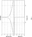
- An example bode plot for a 2000 Hz harmonic regulator with a peak gain of 10 and damping factor of 0.001 is shown in FIG. 1 . It is noted that at frequencies approaching 0, the transfer function phase asymptotically approaches 90 degrees of lead, whereas at frequencies approaching infinity the phase lead asymptotically approaches 90 degrees of lag.
- a large gain at the controller resonance frequency (which is matched to the harmonic frequency to be controlled) is desired.
- a low value of damping is used such that the gain rolls off very quickly away from the desired control frequency.
- Higher values of damping broaden the bandwidth of the controller increasing its response speed, however, higher values also increase gain outside of the control band which is not desired. Due to low damping, phase shifts very quickly from nearly 90 degrees leading to nearly 90 degrees lagging in proximity to the resonant frequency.
- the transfer function C(s) 210 of the controller and transfer function G(s) 220 of the plant being controlled are shown.
- the system 200 provides the output of G(s) 230 as negative feedback to the input of the controller transfer function C(s) 210.
- the loop gain L(s) (which is the product of C(s) and G(s)) is assessed for phase margin and gain margin. It is common for the plant to induce a destabilizing phase lag which increases with frequency. This phase lag will occur due to instrumentation, discrete system effects, filter impedance effects, and load impedance effects. In the presence of harmonic regulators it is common for this to result in negative phase margin (e.g., instability) at some frequencies (particularly higher frequencies). Therefore, control of some frequencies may not be possible without modification.
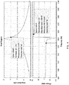
- the bode plot depicts 95.7 degrees of additional phase lead before the phase at the first crossover frequency exceeds +180 degrees, and 95.7 degrees of additional phase lag may be added before the phase at the second crossover frequency decreases below -180 degrees.
- the techniques described herein are for a method and controller for compensating loop transfer function delays that would otherwise make a harmonic regulator unstable or have decreased performance.
- the techniques described herein provide for modifying a controller from having only a harmonic regulator transfer function to having a time delay inserted before or after the harmonic regulator to achieve stability and thus improve the power quality.
- the controller includes a harmonic regulator transfer function HR(s), and a time delay M(s).
- HR(s) the harmonic regulator transfer function
- M(s) the time delay
- the time delay can be inserted before the harmonic regulator. In other embodiments, the time delay can be inserted after the harmonic regulator.
- the harmonic regulator HR(s) has very narrowband performance, therefore it is only able to act on error that is periodic at the controller resonant frequency (or very close to the resonance frequency). Since the error is periodic, known delay in the plant can be compensated by adding even more delay to the loop, such that the total loop delay is equal to an integer number of control frequency periods.
- M(s) is equal to e - 2* tcomp and G(s) is set equal to e -2* tplant .
- System 520 provides the loop delay M(s) is coupled to the output of the harmonic regulator HR(s).
- System 530 provides a single loop delay M(s), coupled to multiple harmonic regulators HR1(s) and HR2(s).
- System 540 provides separate loop delays M1(s) and M2(s) coupled to multiple harmonic regulators HR1(s) and HR2(s), respectively. It should be understood that other configurations can be implemented to improve the power quality of a system and are not limited by the examples shown in FIG. 5 .
- the harmonic regulator will be stable if the loop delay is n / (2000) seconds, where n is an integer. Assuming that we want to control several harmonics of 400 Hz, in addition to 2000 Hz, the loop delay is set to 1/400 or 0.0025 seconds. If the system delay tplant is known to be 150 ⁇ s, solving for tcomp results in a desired added delay of 0.00235 seconds.
- FIG. 6 illustrates a bode plot for the system of FIG. 5 where the controller incorporates the added time delay into the system to improve the phase margin of the system.
- FIG. 7 illustrates a scaled view of the bode plot of FIG. 6 . Due to the added loop delay M(s), there is now 85 degrees of phase margin at the upper and lower unity gain crossover frequencies. Therefore, the system is now stable. In one or more embodiments, the loop delay is observed during the operation of the system. The measured delay is used to select an added tcomp compensation delay.
- the controller may be implemented in a digital control system.
- the controller transfer functions are designed in continuous time and then converted to discrete time. The time delays are then added by incorporating the proper number of sample delays in discrete time.
- the results can be provided to an operator and display in graphical or textual representation representing the performance of the system.
- the results can be transmitted to another system, remote and/or local, for further analysis.
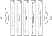
- FIG. 8 a flowchart of a method 800 for implementing a harmonic regulator with delay compensation is shown.
- the method 800 begins at block 802 and proceeds to block 804 which provides for receiving, at a controller, voltage feedback from a power system.
- Block 806 provides for applying a harmonic regulator to each distortion frequency under control and proceeds to block 808 which applies a pre-determined delay to the control signal.
- the method 800 at block 810 provides for scaling the delayed compensator waveform output 808 and adding it to the power source voltage reference waveform.
- Block 812 provides the conditioned power to a load, using the conditioned power source voltage reference waveform output of block 810.
- the method 800 ends at block 814. It is to be understood the method 800 can be continuously repeated.
- the method 800 can include one or more steps of 804-812 or different and/or additional steps and is not limited by the steps provided above.
- FIG. 9 a computer program product 900 in accordance with an embodiment that includes a computer-readable storage medium 902 and program instructions 904 is generally shown.
- the technical effects and benefits include implementing delay compensation which enables control and reduction of harmonic distortions at frequencies which otherwise could not be controlled with harmonic regulators.
- the technical effects and benefits also include a reducing the system voltage distortion in the presence of non-linear loads.
- the line-replaceable unit (LRU) weight is reduced due to decreased LRU power rating required to maintain system voltage distortion within acceptable limits.
Landscapes
- Engineering & Computer Science (AREA)
- Power Engineering (AREA)
- Supply And Distribution Of Alternating Current (AREA)
- Amplifiers (AREA)
- Control Of Electric Motors In General (AREA)
Abstract
Description
- The present invention generally relates to power quality, and more specifically to methods of controlling a power source to reduce voltage waveform distortion.
- The quality of power delivered to electrical loads is critical for their proper operation. The quality of power delivered to electrical loads can be measured by how closely the applied voltage waveform resembles a desired, ideal, waveform shape. For alternating current (AC) power systems, the ideal waveform shape is a sine wave at a single (fundamental) frequency. Deviation from the ideal waveform shape is referred to as distortion. Typically, distortion is comprised of undesired frequency components that occur at multiples of the fundamental frequency; these frequencies are otherwise known as harmonics.
- According to an embodiment, a system implementing a harmonic regulator with loop delay compensation includes a power system, and a controller coupled to the power system, wherein the controller is coupled to the power system. The controller further includes a harmonic regulator configured to remove distortion from power provided by the power system, and a delay component configured to add delay to the power from the power system, wherein an output of the controller is provided to a load and provided as feedback to an input of the controller.
- In addition to one or more of the features described herein, or as an alternative, further embodiments include a delay component that is coupled to an input of the harmonic regulator.
- In addition to one or more of the features described herein, or as an alternative, further embodiments include a delay component that is coupled to an output of the harmonic regulator.
- In addition to one or more of the features described herein, or as an alternative, further embodiments include a delay component that is based at least in part on an integer number of sample delays in discrete time based on the control frequency.
- In addition to one or more of the features described herein, or as an alternative, further embodiments include harmonic regulators that include a plurality of harmonic regulators and the delay components include a plurality of delay components, wherein the plurality of harmonic regulators are coupled to a corresponding a delay component of the plurality of delay components.
- In addition to one or more of the features described herein, or as an alternative, further embodiments include independently selecting gain parameter for the harmonic regulator.
- In addition to one or more of the features described herein, or as an alternative, further embodiments include a delay component that is coupled to a plurality of harmonic regulators.
- According to another embodiment, a method for implementing a harmonic regulator with loop delay compensation is provided. The computer-implemented method includes receiving, at a controller, voltage feedback from a power system and applying a harmonic regulator to each distortion frequency to be compensated. The computer-implemented method also includes applying a predetermined delay to an output of the harmonic regulator, scaling the delayed output and adding it to a power source voltage reference waveform, and providing condition power to a load, using the conditioned power source voltage reference waveform.
- In addition to one or more of the features described herein, or as an alternative, further embodiments include a pre-determined delay component that is coupled to an input of the harmonic regulator.
- In addition to one or more of the features described herein, or as an alternative, further embodiments include a pre-determined delay component that is coupled to an output of the harmonic regulator.
- In addition to one or more of the features described herein, or as an alternative, further embodiments include a pre-determined delay component that is based at least in part on an integer number of sample delays in discrete time based on the control frequency.
- In addition to one or more of the features described herein, or as an alternative, further embodiments include a harmonic regulator that includes a plurality of harmonic regulators and the delay components include a plurality of delay components, wherein the plurality of harmonic regulators are coupled to a corresponding delay component of the plurality of delay components.
- In addition to one or more of the features described herein, or as an alternative, further embodiments include individually selecting a gain for each harmonic regulator.
- In addition to one or more of the features described herein, or as an alternative, further embodiments include a pre-determined delay component that is coupled to a plurality of harmonic regulators.
- According to another embodiment, a controller for implementing a harmonic regulator with loop delay compensation is provided. The controller is coupled to a power system, wherein the controller is coupled to the power system and further includes a harmonic regulator configured to remove distortion from power provided by the power system, and a delay component configured to add delay to the power from the power system, wherein an output of the controller is provided to a load and provided as feedback to an input of the controller.
- In addition to one or more of the features described herein, or as an alternative, further embodiments include a delay component that is coupled to an input of the harmonic regulator.
- In addition to one or more of the features described herein, or as an alternative, further embodiments include a delay component that is coupled to an output of the harmonic regulator.
- In addition to one or more of the features described herein, or as an alternative, further embodiments include a delay component that is based at least in part on an integer number of sample delays in discrete time based on the control frequency.
- In addition to one or more of the features described herein, or as an alternative, further embodiments include harmonic regulators that include a plurality of harmonic regulators and the delay components include a plurality of delay components, wherein the plurality of harmonic regulators are coupled to a corresponding a delay component of the plurality of delay components.
- In addition to one or more of the features described herein, or as an alternative, further embodiments include a delay component is coupled to a plurality of harmonic regulators.
- Technical effects of embodiments of the present disclosure include incorporating plant delay compensation to enable control and reduction of harmonic distortion at frequencies which otherwise could not be controlled with a harmonic regulator alone.
- The foregoing features and elements may be combined in various combinations without exclusivity, unless expressly indicated otherwise. These features and elements as well as the operation thereof will become more apparent in light of the following description and the accompanying drawings. It should be understood, however, that the following description and drawings are intended to be illustrative and explanatory in nature and non-limiting.
- The following descriptions should not be considered limiting in any way. With reference to the accompanying drawings, like elements are numbered alike:
-
FIG. 1 is a bode plot of a harmonic regulator; -
FIG. 2 is a simplified block diagram of a feedback-controlled dynamic system, depicting the system loop gain L(s), wherein C(s) is the compensator transfer function and G(s) is the transfer function of the plant being controlled; -
FIG. 3 depicts a phase margin of the system shown inFIG. 2 , wherein C(s) is the transfer function depicted in theFIG. 1 bode plot, and G(s) is unity; -
FIG. 4 depicts the gain and phase margin of the system shown inFIG. 2 , wherein C(s) is the transfer function depicted in theFIG. 1 bode plot, and G(s) is a 150µs delay; -
FIG. 5 depicts a harmonic regulator with delay compensation in accordance with one or more embodiments; -
FIG. 6 depicts a bode plot for a harmonic regulator with delay compensation in accordance with one or more embodiments; -
FIG. 7 depicts the bode plot ofFIG. 6 , between 1900Hz and 2100Hz, with phase margin shown in accordance with one or more embodiments; -
FIG. 8 depicts a flowchart of a method for implementing a harmonic regulator with delay compensation in accordance with one or more embodiments; and -
FIG. 9 depicts a computer program product in accordance with one or more embodiments. - Various electrical loads have different impacts on system power quality. These electrical loads can be classified as either linear or non-linear.
- Inductive, resistive and capacitive loads are classified as linear loads, since they produce current flow at a given frequency proportional to the applied voltage at that frequency. When provided ideal (non-distorted) AC voltage, ideal current will flow in a linear load.
- Some electrical loads, however, are non-linear, such as diode rectifiers. In non-linear loads, current flow is not always proportional to the applied voltage. In these loads harmonic currents may flow even when no voltage harmonics are applied.
- Non-linear load current causes distortion in the voltage dropped across any source impedance between the electrical load and the source. Voltage delivered at a load is the sum of the source voltage and the voltage drop across the source impedance. Consequently, an ideal voltage source will still produce distorted voltage at electrical loads, if one of the loads is non-linear and causing a distorted source impedance voltage drop.
- A conventional technique for reducing distortion in the voltage delivered to loads in the presence of non-linear loads is to reduce the source impedance (and thus the distorted voltage drop across the source impedance). This method is effective, however to reduce source impedance the power source electrical power rating must typically be increased. This results in the electrical power source (e.g. generator or solid-state power converter) having a larger physical volume and weight than would otherwise be necessary. Thus, there is a need in the art for alternate methods of reducing distortion in the voltage delivered to loads when non-linear loads are present which do not require increasing ratings of electrical power sources. The present disclosure provides a solution for this need.
- An example non-linear load is a 6-pulse rectifier with load current total harmonic distortion (THD) greater than 25%. The highly distorted current will cause a distorted voltage drop across the source inductance of the aircraft power source (generator or VSCF converter) resulting in large voltage distortion on the aircraft electrical power buses. Other aircraft electrical devices may not have been designed for operation with the distorted voltage created by the non-linear load. This is a systems power quality problem; the combined design of the electrical power source and the distortion-causing loads determine resultant power quality, and neighboring loads must be designed for operation at that power quality.
- Active compensation for distortions can be programmed at multiples of the fundamental frequency (i.e. 400 Hz for a constant frequency aircraft electrical power system). The controller may be used to reduce distortion at the 3rd, 5th, 7th, 9th, 11th, and 13th harmonics of the fundamental frequency. A harmonic regulator is well-suited for harmonic distortion compensation of aircraft variable speed constant frequency (VSCF) converters, since the output frequency is fixed at 400 Hz. A transfer function for each harmonic regulator can be expressed by
Equation 1 below:
FIG. 1 . It is noted that at frequencies approaching 0, the transfer function phase asymptotically approaches 90 degrees of lead, whereas at frequencies approaching infinity the phase lead asymptotically approaches 90 degrees of lag. To reject disturbance at a given harmonic frequency, a large gain at the controller resonance frequency (which is matched to the harmonic frequency to be controlled) is desired. A low value of damping is used such that the gain rolls off very quickly away from the desired control frequency. Higher values of damping broaden the bandwidth of the controller increasing its response speed, however, higher values also increase gain outside of the control band which is not desired. Due to low damping, phase shifts very quickly from nearly 90 degrees leading to nearly 90 degrees lagging in proximity to the resonant frequency. - As shown in
FIG. 2 , the system 200 includes loop gain L(s) = C(s) x G(s). The transfer function C(s) 210 of the controller and transfer function G(s) 220 of the plant being controlled are shown. The system 200 provides the output of G(s) 230 as negative feedback to the input of the controller transfer function C(s) 210. - For stability, the loop gain L(s) (which is the product of C(s) and G(s)) is assessed for phase margin and gain margin. It is common for the plant to induce a destabilizing phase lag which increases with frequency. This phase lag will occur due to instrumentation, discrete system effects, filter impedance effects, and load impedance effects. In the presence of harmonic regulators it is common for this to result in negative phase margin (e.g., instability) at some frequencies (particularly higher frequencies). Therefore, control of some frequencies may not be possible without modification.
- If the controller has the same transfer function displayed in
FIG. 1 , and a plant transfer function G(s) = 1, then the system 200 will be stable as shown inFIG. 3 . As provided inFIG. 3 , the bode plot depicts 95.7 degrees of additional phase lead before the phase at the first crossover frequency exceeds +180 degrees, and 95.7 degrees of additional phase lag may be added before the phase at the second crossover frequency decreases below -180 degrees. - Referring to system of
FIG. 1 , assume 150 µs delay is introduced due to sampling effects, that is G(s) = e -s*0.00015. The resultant bode plot of the loop transfer function is now shown inFIG. 4 . The system is now unstable since the phase delay at the second crossover frequency decreases below -180. This limits the ability of harmonic regulators to be used for VSCF power quality improvements. - The techniques described herein are for a method and controller for compensating loop transfer function delays that would otherwise make a harmonic regulator unstable or have decreased performance. The techniques described herein provide for modifying a controller from having only a harmonic regulator transfer function to having a time delay inserted before or after the harmonic regulator to achieve stability and thus improve the power quality.
- Now referring to
FIG. 5 , a block diagram of a controller 500 implementing delay compensation in accordance with one or more embodiments is shown. As shown, the controller includes a harmonic regulator transfer function HR(s), and a time delay M(s). In some embodiments, the time delay can be inserted before the harmonic regulator. In other embodiments, the time delay can be inserted after the harmonic regulator. - The harmonic regulator HR(s) has very narrowband performance, therefore it is only able to act on error that is periodic at the controller resonant frequency (or very close to the resonance frequency). Since the error is periodic, known delay in the plant can be compensated by adding even more delay to the loop, such that the total loop delay is equal to an integer number of control frequency periods. In this example, M(s) is equal to e -2*tcomp and G(s) is set equal to e -2* tplant.
- Other configurations including 510 are shown but achieve benefits of the aforementioned configuration.
System 520 provides the loop delay M(s) is coupled to the output of the harmonic regulator HR(s).System 530 provides a single loop delay M(s), coupled to multiple harmonic regulators HR1(s) and HR2(s).System 540 provides separate loop delays M1(s) and M2(s) coupled to multiple harmonic regulators HR1(s) and HR2(s), respectively. It should be understood that other configurations can be implemented to improve the power quality of a system and are not limited by the examples shown inFIG. 5 . - The loop delay can be set equal to n / resonance frequency component.
Equation 2 provides the following:
- The resulting bode plots of the loop gain with an added 0.00235 second delay are shown in
FIG. 6 and7 . The magnitude of the gain is greater than 1 near 2000 Hz so the phase margin only needs to be assessed at the gain crossover frequencies just above and below 2000 Hz.FIG. 6 illustrates a bode plot for the system ofFIG. 5 where the controller incorporates the added time delay into the system to improve the phase margin of the system. -
FIG. 7 illustrates a scaled view of the bode plot ofFIG. 6 . Due to the added loop delay M(s), there is now 85 degrees of phase margin at the upper and lower unity gain crossover frequencies. Therefore, the system is now stable. In one or more embodiments, the loop delay is observed during the operation of the system. The measured delay is used to select an added tcomp compensation delay. - Other factors that can cause variations in the system gain and cause phase delays that do not linearly increase with frequency include the output filter, output load, and instrumentation. For such systems, the harmonic regulator gain, k, may be varied to set the desired gain at each harmonic. Additionally, the value of tcomp used for each harmonic may be separately tuned to account for nonlinear phase characteristics in the system such as shown in
configuration 540 ofFIG. 5 . In some embodiments, the controller may be implemented in a digital control system. The controller transfer functions are designed in continuous time and then converted to discrete time. The time delays are then added by incorporating the proper number of sample delays in discrete time. - In one or more embodiments, the results can be provided to an operator and display in graphical or textual representation representing the performance of the system. In some embodiments, the results can be transmitted to another system, remote and/or local, for further analysis.
- Now referring to
FIG. 8 , a flowchart of amethod 800 for implementing a harmonic regulator with delay compensation is shown. Themethod 800 begins atblock 802 and proceeds to block 804 which provides for receiving, at a controller, voltage feedback from a power system.Block 806 provides for applying a harmonic regulator to each distortion frequency under control and proceeds to block 808 which applies a pre-determined delay to the control signal. Themethod 800 atblock 810 provides for scaling the delayedcompensator waveform output 808 and adding it to the power source voltage reference waveform.Block 812 provides the conditioned power to a load, using the conditioned power source voltage reference waveform output ofblock 810. Themethod 800 ends atblock 814. It is to be understood themethod 800 can be continuously repeated. In addition, themethod 800 can include one or more steps of 804-812 or different and/or additional steps and is not limited by the steps provided above. - Referring now to
FIG. 9 , acomputer program product 900 in accordance with an embodiment that includes a computer-readable storage medium 902 andprogram instructions 904 is generally shown. - The technical effects and benefits include implementing delay compensation which enables control and reduction of harmonic distortions at frequencies which otherwise could not be controlled with harmonic regulators. The technical effects and benefits also include a reducing the system voltage distortion in the presence of non-linear loads. Also, the line-replaceable unit (LRU) weight is reduced due to decreased LRU power rating required to maintain system voltage distortion within acceptable limits.
- A detailed description of one or more embodiments of the disclosed apparatus and method are presented herein by way of exemplification and not limitation with reference to the Figures.
- The term "about" is intended to include the degree of error associated with measurement of the particular quantity based upon the equipment available at the time of filing the application.
- The terminology used herein is for the purpose of describing particular embodiments only and is not intended to be limiting of the present disclosure. As used herein, the singular forms "a", "an" and "the" are intended to include the plural forms as well, unless the context clearly indicates otherwise. It will be further understood that the terms "comprises" and/or "comprising," when used in this specification, specify the presence of stated features, integers, steps, operations, elements, and/or components, but do not preclude the presence or addition of one or more other features, integers, steps, operations, element components, and/or groups thereof.
- While the present disclosure has been described with reference to an exemplary embodiment or embodiments, it will be understood by those skilled in the art that various changes may be made and equivalents may be substituted for elements thereof without departing from the scope of the present disclosure. In addition, many modifications may be made to adapt a particular situation or material to the teachings of the present disclosure without departing from the essential scope thereof. Therefore, it is intended that the present disclosure not be limited to the particular embodiment disclosed as the best mode contemplated for carrying out this present disclosure, but that the present disclosure will include all embodiments falling within the scope of the claims.
Claims (15)
- A system (200) for implementing a harmonic regulator with loop delay compensation comprising:a power system; anda controller coupled to the power system, wherein the controller is coupled to the power system and further comprises:a harmonic regulator configured to remove distortion from power provided by the power system;a delay component configured to add delay to the power from the power system, wherein an output of the controller is provided to a load and provided as feedback to an input of the controller.
- The system of claim 1, wherein the delay component is coupled to an input of the harmonic regulator.
- The system of claim 1, wherein the delay component is coupled to an output of the harmonic regulator.
- The system of any preceding claim, wherein the delay component is based at least in part on an integer number of sample delays in discrete time based on the control frequency.
- The system of any preceding claim, wherein the harmonic regulators include a plurality of harmonic regulators and the delay components include a plurality of delay components, wherein the plurality of harmonic regulators are coupled to a corresponding a delay component of the plurality of delay components.
- The system of any preceding claim, wherein gain for the harmonic regulator is independently selected.
- The system of any of claims 4 to 6, wherein the delay component is coupled to a plurality of harmonic regulators.
- A controller for implementing a harmonic regulator with loop delay compensation, the controller comprising:
a storage medium, the storage medium being coupled to a processor and the system of any preceding claim. - The controller of claim 8, wherein the delay component is coupled to a plurality of harmonic regulators.
- A computer-implemented method for operating a harmonic regulator with loop delay compensation, the computer-implemented method comprising:receiving, at a controller, voltage feedback from a power system;applying a harmonic regulator to each distortion frequency to be compensated;applying a predetermined delay to an output of the harmonic regulator;scaling the delayed output and adding it to a power source voltage reference waveform; andproviding condition power to a load, using the conditioned power source voltage reference waveform.
- The computer-implemented method of claim 10, wherein the pre-determined delay component is coupled to an input of the harmonic regulator.
- The computer-implemented method of claim 10, wherein the pre-determined delay component is coupled to an output of the harmonic regulator.
- The computer-implemented method of claim 10, wherein the pre-determined delay component is based at least in part on an integer number of sample delays in discrete time based on the control frequency.
- The computer-implemented method of claim 10, wherein the harmonic regulator includes a plurality of harmonic regulators and the delay components include a plurality of delay components, wherein the plurality of harmonic regulators are coupled to a corresponding delay component of the plurality of delay components.
- The computer-implemented method of claim 10, further comprising individually selecting a gain for each harmonic regulator, and/or
wherein the pre-determined delay component is coupled to a plurality of harmonic regulators.
Applications Claiming Priority (1)
| Application Number | Priority Date | Filing Date | Title |
|---|---|---|---|
| US16/283,874 US10658919B1 (en) | 2019-02-25 | 2019-02-25 | Harmonic regulator with loop delay compensation |
Publications (1)
| Publication Number | Publication Date |
|---|---|
| EP3700041A1 true EP3700041A1 (en) | 2020-08-26 |
Family
ID=68916252
Family Applications (1)
| Application Number | Title | Priority Date | Filing Date |
|---|---|---|---|
| EP19215800.4A Pending EP3700041A1 (en) | 2019-02-25 | 2019-12-12 | Harmonic regulator with loop delay compensation |
Country Status (3)
| Country | Link |
|---|---|
| US (1) | US10658919B1 (en) |
| EP (1) | EP3700041A1 (en) |
| KR (1) | KR102705399B1 (en) |
Families Citing this family (1)
| Publication number | Priority date | Publication date | Assignee | Title |
|---|---|---|---|---|
| US20220216781A1 (en) | 2021-01-06 | 2022-07-07 | Hamilton Sundstrand Corporation | Harmonic regulators with phase compensation |
Citations (2)
| Publication number | Priority date | Publication date | Assignee | Title |
|---|---|---|---|---|
| CA2767709A1 (en) * | 2011-02-14 | 2012-08-14 | Siemens Aktiengesellschaft | Controller for a power converter and method of operating the same |
| US20160349717A1 (en) * | 2014-01-30 | 2016-12-01 | Meidensha Corporation | Periodic external disturbance suppression control device |
Family Cites Families (17)
| Publication number | Priority date | Publication date | Assignee | Title |
|---|---|---|---|---|
| US6472775B1 (en) * | 2001-11-30 | 2002-10-29 | Ballard Power Systems Corporation | Method and system for eliminating certain harmonics in a distributed power system |
| JP2004096911A (en) * | 2002-08-30 | 2004-03-25 | Railway Technical Res Inst | PWM converter system |
| US6756702B1 (en) | 2002-12-18 | 2004-06-29 | Honeywell International Inc. | Transport-lag compensator |
| US6977827B2 (en) * | 2004-03-22 | 2005-12-20 | American Superconductor Corporation | Power system having a phase locked loop with a notch filter |
| US7099165B1 (en) * | 2005-04-12 | 2006-08-29 | Hamilton Sundstrand Corporation | Network harmonic scrubber |
| US9876599B2 (en) * | 2007-12-17 | 2018-01-23 | Avago Technologies General Ip (Singapore) Pte. Ltd. | System(s), method(s), and apparatus for accurate detection of the end of stream |
| US8796884B2 (en) * | 2008-12-20 | 2014-08-05 | Solarbridge Technologies, Inc. | Energy conversion systems with power control |
| US8629579B2 (en) * | 2010-03-24 | 2014-01-14 | Hamilton Sundstrand Corporation | Active switching ripple filter |
| US20110292699A1 (en) * | 2010-05-26 | 2011-12-01 | Texas Instruments Incorporated | Systems and Methods for Distortion Reduction |
| US8810182B2 (en) * | 2010-09-30 | 2014-08-19 | Rockwell Automation Technologies, Inc. | Adaptive harmonic reduction apparatus and methods |
| CN102868285A (en) | 2011-07-06 | 2013-01-09 | 南京南瑞继保电气有限公司 | Resonance control method |
| KR101333828B1 (en) * | 2012-01-31 | 2013-11-29 | 울산대학교 산학협력단 | Control apparatus and method for power generator system |
| US9048817B2 (en) * | 2013-03-29 | 2015-06-02 | Hamilton Sundstrand Corporation | Voltage fed feed forward active EMI filter |
| WO2014174667A1 (en) | 2013-04-26 | 2014-10-30 | 富士電機株式会社 | Resonance suppression device |
| US9293985B2 (en) * | 2013-06-14 | 2016-03-22 | Hamilton Sundstrand Corporation | Method of reducing input current distortion in a rectifier |
| JP5850117B2 (en) * | 2013-09-30 | 2016-02-03 | ダイキン工業株式会社 | Power converter |
| EP3035511B1 (en) | 2014-12-19 | 2018-08-22 | ABB Schweiz AG | Method for damping resonant component of common-mode current of multi-phase power converter |
-
2019
- 2019-02-25 US US16/283,874 patent/US10658919B1/en active Active
- 2019-12-12 EP EP19215800.4A patent/EP3700041A1/en active Pending
- 2019-12-13 KR KR1020190166307A patent/KR102705399B1/en active Active
Patent Citations (2)
| Publication number | Priority date | Publication date | Assignee | Title |
|---|---|---|---|---|
| CA2767709A1 (en) * | 2011-02-14 | 2012-08-14 | Siemens Aktiengesellschaft | Controller for a power converter and method of operating the same |
| US20160349717A1 (en) * | 2014-01-30 | 2016-12-01 | Meidensha Corporation | Periodic external disturbance suppression control device |
Non-Patent Citations (4)
| Title |
|---|
| CHEN MANLIN ET AL: "Accurate and Fast Harmonic Detection Based on the Generalized Trigonometric Function Delayed Signal Cancellation", IEEE ACCESS, vol. 7, 1 January 2019 (2019-01-01), pages 3438 - 3447, XP011696474, DOI: 10.1109/ACCESS.2018.2886174 * |
| HAUSMANN M ET AL: "Harmonic compensation in a load emulation system using different control techniques", TELECOMMUNICATIONS ENERGY CONFERENCE (INTELEC), 2012 IEEE 34TH INTERNATIONAL, IEEE, 30 September 2012 (2012-09-30), pages 1 - 7, XP032276446, ISBN: 978-1-4673-0999-8, DOI: 10.1109/INTLEC.2012.6374496 * |
| SHUDE YANG ET AL: "Voltage Feedforward Control with Time-Delay Compensation for Grid-Connected Converters", JOURNAL OF POWER ELECTRONICS, vol. 16, no. 5, 20 September 2016 (2016-09-20), pages 1833 - 1842, XP055663848, ISSN: 1598-2092, DOI: 10.6113/JPE.2016.16.5.1833 * |
| YUAN CHANG ET AL: "A Novel Control of Series Active Power Filter without Harmonics Detection", POWER ELECTRONICS SPECIALISTS CONFERENCE, 2007. PESC 2007. IEEE, IEEE, PISCATAWAY, NJ, USA, 17 June 2007 (2007-06-17), pages 1112 - 1115, XP031218441, ISBN: 978-1-4244-0654-8 * |
Also Published As
| Publication number | Publication date |
|---|---|
| KR20200103522A (en) | 2020-09-02 |
| KR102705399B1 (en) | 2024-09-11 |
| US10658919B1 (en) | 2020-05-19 |
Similar Documents
| Publication | Publication Date | Title |
|---|---|---|
| EP2763306B1 (en) | Power converter | |
| EP0968559B1 (en) | Method and device for inductive transmission of electric power to a plurality of mobile consumers | |
| US9231469B2 (en) | Auto-tuning current loop compensation for power factor correction controller | |
| US10944264B2 (en) | Active filter for resonance reduction | |
| Li et al. | Direct-current vector control of three-phase grid-connected rectifier–inverter | |
| EP2871740B1 (en) | Control of DC transmission lines | |
| Pradhan et al. | Small-signal modeling and multivariable PI control design of VSC-HVDC transmission link | |
| DE102017128073A1 (en) | Method for operating a voltage converter and corresponding control device | |
| US10658919B1 (en) | Harmonic regulator with loop delay compensation | |
| Sonnenschein et al. | Comparison of time‐domain and frequency‐domain control schemes for shunt active filters | |
| EP3316435A1 (en) | Resonance suppression device | |
| US10715029B1 (en) | Generator systems and controllers | |
| EP0033842A2 (en) | Method for mains feedback of a line commutated direct converter and control circuit therefor | |
| EP2816698B1 (en) | Systems and methods for tuning the control of a shunt active power filter over a variable frequency | |
| CN106463962B (en) | Method and apparatus for reducing voltage fluctuations in a power supply network | |
| CN114142761A (en) | Dynamic resonance control of grid-connected power converters | |
| Belloni et al. | A series compensation device for the LV power quality improvement | |
| EP3340453A1 (en) | Method of configuring a closed-loop control system | |
| Mukherjee et al. | Impedance shaping for improved load sharing among inverters in AC microgrids | |
| EP2023474B1 (en) | Apparatus for providing AC voltage | |
| EP3694071A1 (en) | Generator systems and controllers | |
| EP4027475A1 (en) | Harmonic regulators with phase compensation | |
| EP3382883A1 (en) | Phase adjusting circuit, inverter circuit, and power supply system | |
| JP6879652B1 (en) | Self-excited electrostatic compensator | |
| Hock et al. | Frequency compensation for stand alone voltage-controlled DSTATCOM |
Legal Events
| Date | Code | Title | Description |
|---|---|---|---|
| PUAI | Public reference made under article 153(3) epc to a published international application that has entered the european phase |
Free format text: ORIGINAL CODE: 0009012 |
|
| STAA | Information on the status of an ep patent application or granted ep patent |
Free format text: STATUS: THE APPLICATION HAS BEEN PUBLISHED |
|
| AK | Designated contracting states |
Kind code of ref document: A1 Designated state(s): AL AT BE BG CH CY CZ DE DK EE ES FI FR GB GR HR HU IE IS IT LI LT LU LV MC MK MT NL NO PL PT RO RS SE SI SK SM TR |
|
| AX | Request for extension of the european patent |
Extension state: BA ME |
|
| STAA | Information on the status of an ep patent application or granted ep patent |
Free format text: STATUS: REQUEST FOR EXAMINATION WAS MADE |
|
| 17P | Request for examination filed |
Effective date: 20210224 |
|
| RBV | Designated contracting states (corrected) |
Designated state(s): AL AT BE BG CH CY CZ DE DK EE ES FI FR GB GR HR HU IE IS IT LI LT LU LV MC MK MT NL NO PL PT RO RS SE SI SK SM TR |
|
| STAA | Information on the status of an ep patent application or granted ep patent |
Free format text: STATUS: EXAMINATION IS IN PROGRESS |
|
| 17Q | First examination report despatched |
Effective date: 20230523 |