EP3699963A1 - Semiconductor light emitting diode and method of manufacturing its substrate - Google Patents
Semiconductor light emitting diode and method of manufacturing its substrate Download PDFInfo
- Publication number
- EP3699963A1 EP3699963A1 EP20162467.3A EP20162467A EP3699963A1 EP 3699963 A1 EP3699963 A1 EP 3699963A1 EP 20162467 A EP20162467 A EP 20162467A EP 3699963 A1 EP3699963 A1 EP 3699963A1
- Authority
- EP
- European Patent Office
- Prior art keywords
- protrusion
- substrate
- protrusions
- light emitting
- layer
- Prior art date
- Legal status (The legal status is an assumption and is not a legal conclusion. Google has not performed a legal analysis and makes no representation as to the accuracy of the status listed.)
- Withdrawn
Links
Images


Classifications
-
- H—ELECTRICITY
- H01—ELECTRIC ELEMENTS
- H01L—SEMICONDUCTOR DEVICES NOT COVERED BY CLASS H10
- H01L33/00—Semiconductor devices with at least one potential-jump barrier or surface barrier specially adapted for light emission; Processes or apparatus specially adapted for the manufacture or treatment thereof or of parts thereof; Details thereof
- H01L33/02—Semiconductor devices with at least one potential-jump barrier or surface barrier specially adapted for light emission; Processes or apparatus specially adapted for the manufacture or treatment thereof or of parts thereof; Details thereof characterised by the semiconductor bodies
- H01L33/20—Semiconductor devices with at least one potential-jump barrier or surface barrier specially adapted for light emission; Processes or apparatus specially adapted for the manufacture or treatment thereof or of parts thereof; Details thereof characterised by the semiconductor bodies with a particular shape, e.g. curved or truncated substrate
-
- H—ELECTRICITY
- H01—ELECTRIC ELEMENTS
- H01L—SEMICONDUCTOR DEVICES NOT COVERED BY CLASS H10
- H01L21/00—Processes or apparatus adapted for the manufacture or treatment of semiconductor or solid state devices or of parts thereof
- H01L21/02—Manufacture or treatment of semiconductor devices or of parts thereof
- H01L21/02104—Forming layers
- H01L21/02365—Forming inorganic semiconducting materials on a substrate
- H01L21/02367—Substrates
- H01L21/0237—Materials
- H01L21/0242—Crystalline insulating materials
-
- H—ELECTRICITY
- H01—ELECTRIC ELEMENTS
- H01L—SEMICONDUCTOR DEVICES NOT COVERED BY CLASS H10
- H01L21/00—Processes or apparatus adapted for the manufacture or treatment of semiconductor or solid state devices or of parts thereof
- H01L21/02—Manufacture or treatment of semiconductor devices or of parts thereof
- H01L21/02104—Forming layers
- H01L21/02365—Forming inorganic semiconducting materials on a substrate
- H01L21/02367—Substrates
- H01L21/02428—Structure
- H01L21/0243—Surface structure
-
- H—ELECTRICITY
- H01—ELECTRIC ELEMENTS
- H01L—SEMICONDUCTOR DEVICES NOT COVERED BY CLASS H10
- H01L21/00—Processes or apparatus adapted for the manufacture or treatment of semiconductor or solid state devices or of parts thereof
- H01L21/02—Manufacture or treatment of semiconductor devices or of parts thereof
- H01L21/02104—Forming layers
- H01L21/02365—Forming inorganic semiconducting materials on a substrate
- H01L21/02367—Substrates
- H01L21/02433—Crystal orientation
-
- H—ELECTRICITY
- H01—ELECTRIC ELEMENTS
- H01L—SEMICONDUCTOR DEVICES NOT COVERED BY CLASS H10
- H01L21/00—Processes or apparatus adapted for the manufacture or treatment of semiconductor or solid state devices or of parts thereof
- H01L21/02—Manufacture or treatment of semiconductor devices or of parts thereof
- H01L21/02104—Forming layers
- H01L21/02365—Forming inorganic semiconducting materials on a substrate
- H01L21/02518—Deposited layers
- H01L21/02521—Materials
- H01L21/02538—Group 13/15 materials
- H01L21/0254—Nitrides
-
- H—ELECTRICITY
- H01—ELECTRIC ELEMENTS
- H01L—SEMICONDUCTOR DEVICES NOT COVERED BY CLASS H10
- H01L21/00—Processes or apparatus adapted for the manufacture or treatment of semiconductor or solid state devices or of parts thereof
- H01L21/02—Manufacture or treatment of semiconductor devices or of parts thereof
- H01L21/02104—Forming layers
- H01L21/02365—Forming inorganic semiconducting materials on a substrate
- H01L21/02656—Special treatments
- H01L21/02658—Pretreatments
-
- H—ELECTRICITY
- H01—ELECTRIC ELEMENTS
- H01L—SEMICONDUCTOR DEVICES NOT COVERED BY CLASS H10
- H01L33/00—Semiconductor devices with at least one potential-jump barrier or surface barrier specially adapted for light emission; Processes or apparatus specially adapted for the manufacture or treatment thereof or of parts thereof; Details thereof
- H01L33/005—Processes
- H01L33/0062—Processes for devices with an active region comprising only III-V compounds
- H01L33/0066—Processes for devices with an active region comprising only III-V compounds with a substrate not being a III-V compound
- H01L33/007—Processes for devices with an active region comprising only III-V compounds with a substrate not being a III-V compound comprising nitride compounds
-
- H—ELECTRICITY
- H01—ELECTRIC ELEMENTS
- H01L—SEMICONDUCTOR DEVICES NOT COVERED BY CLASS H10
- H01L21/00—Processes or apparatus adapted for the manufacture or treatment of semiconductor or solid state devices or of parts thereof
- H01L21/02—Manufacture or treatment of semiconductor devices or of parts thereof
- H01L21/02104—Forming layers
- H01L21/02365—Forming inorganic semiconducting materials on a substrate
- H01L21/02612—Formation types
- H01L21/02617—Deposition types
- H01L21/02636—Selective deposition, e.g. simultaneous growth of mono- and non-monocrystalline semiconductor materials
- H01L21/02647—Lateral overgrowth
-
- H—ELECTRICITY
- H01—ELECTRIC ELEMENTS
- H01L—SEMICONDUCTOR DEVICES NOT COVERED BY CLASS H10
- H01L2224/00—Indexing scheme for arrangements for connecting or disconnecting semiconductor or solid-state bodies and methods related thereto as covered by H01L24/00
- H01L2224/01—Means for bonding being attached to, or being formed on, the surface to be connected, e.g. chip-to-package, die-attach, "first-level" interconnects; Manufacturing methods related thereto
- H01L2224/42—Wire connectors; Manufacturing methods related thereto
- H01L2224/47—Structure, shape, material or disposition of the wire connectors after the connecting process
- H01L2224/48—Structure, shape, material or disposition of the wire connectors after the connecting process of an individual wire connector
- H01L2224/4805—Shape
- H01L2224/4809—Loop shape
- H01L2224/48095—Kinked
-
- H—ELECTRICITY
- H01—ELECTRIC ELEMENTS
- H01L—SEMICONDUCTOR DEVICES NOT COVERED BY CLASS H10
- H01L2224/00—Indexing scheme for arrangements for connecting or disconnecting semiconductor or solid-state bodies and methods related thereto as covered by H01L24/00
- H01L2224/01—Means for bonding being attached to, or being formed on, the surface to be connected, e.g. chip-to-package, die-attach, "first-level" interconnects; Manufacturing methods related thereto
- H01L2224/42—Wire connectors; Manufacturing methods related thereto
- H01L2224/47—Structure, shape, material or disposition of the wire connectors after the connecting process
- H01L2224/48—Structure, shape, material or disposition of the wire connectors after the connecting process of an individual wire connector
- H01L2224/481—Disposition
- H01L2224/48151—Connecting between a semiconductor or solid-state body and an item not being a semiconductor or solid-state body, e.g. chip-to-substrate, chip-to-passive
- H01L2224/48221—Connecting between a semiconductor or solid-state body and an item not being a semiconductor or solid-state body, e.g. chip-to-substrate, chip-to-passive the body and the item being stacked
- H01L2224/48245—Connecting between a semiconductor or solid-state body and an item not being a semiconductor or solid-state body, e.g. chip-to-substrate, chip-to-passive the body and the item being stacked the item being metallic
- H01L2224/48247—Connecting between a semiconductor or solid-state body and an item not being a semiconductor or solid-state body, e.g. chip-to-substrate, chip-to-passive the body and the item being stacked the item being metallic connecting the wire to a bond pad of the item
-
- H—ELECTRICITY
- H01—ELECTRIC ELEMENTS
- H01L—SEMICONDUCTOR DEVICES NOT COVERED BY CLASS H10
- H01L2224/00—Indexing scheme for arrangements for connecting or disconnecting semiconductor or solid-state bodies and methods related thereto as covered by H01L24/00
- H01L2224/01—Means for bonding being attached to, or being formed on, the surface to be connected, e.g. chip-to-package, die-attach, "first-level" interconnects; Manufacturing methods related thereto
- H01L2224/42—Wire connectors; Manufacturing methods related thereto
- H01L2224/47—Structure, shape, material or disposition of the wire connectors after the connecting process
- H01L2224/48—Structure, shape, material or disposition of the wire connectors after the connecting process of an individual wire connector
- H01L2224/484—Connecting portions
- H01L2224/48463—Connecting portions the connecting portion on the bonding area of the semiconductor or solid-state body being a ball bond
- H01L2224/48465—Connecting portions the connecting portion on the bonding area of the semiconductor or solid-state body being a ball bond the other connecting portion not on the bonding area being a wedge bond, i.e. ball-to-wedge, regular stitch
-
- H—ELECTRICITY
- H01—ELECTRIC ELEMENTS
- H01L—SEMICONDUCTOR DEVICES NOT COVERED BY CLASS H10
- H01L2224/00—Indexing scheme for arrangements for connecting or disconnecting semiconductor or solid-state bodies and methods related thereto as covered by H01L24/00
- H01L2224/01—Means for bonding being attached to, or being formed on, the surface to be connected, e.g. chip-to-package, die-attach, "first-level" interconnects; Manufacturing methods related thereto
- H01L2224/42—Wire connectors; Manufacturing methods related thereto
- H01L2224/47—Structure, shape, material or disposition of the wire connectors after the connecting process
- H01L2224/49—Structure, shape, material or disposition of the wire connectors after the connecting process of a plurality of wire connectors
- H01L2224/491—Disposition
- H01L2224/49105—Connecting at different heights
- H01L2224/49107—Connecting at different heights on the semiconductor or solid-state body
-
- H—ELECTRICITY
- H01—ELECTRIC ELEMENTS
- H01L—SEMICONDUCTOR DEVICES NOT COVERED BY CLASS H10
- H01L25/00—Assemblies consisting of a plurality of individual semiconductor or other solid state devices ; Multistep manufacturing processes thereof
- H01L25/16—Assemblies consisting of a plurality of individual semiconductor or other solid state devices ; Multistep manufacturing processes thereof the devices being of types provided for in two or more different main groups of groups H01L27/00 - H01L33/00, or in a single subclass of H10K, H10N, e.g. forming hybrid circuits
- H01L25/167—Assemblies consisting of a plurality of individual semiconductor or other solid state devices ; Multistep manufacturing processes thereof the devices being of types provided for in two or more different main groups of groups H01L27/00 - H01L33/00, or in a single subclass of H10K, H10N, e.g. forming hybrid circuits comprising optoelectronic devices, e.g. LED, photodiodes
-
- H—ELECTRICITY
- H01—ELECTRIC ELEMENTS
- H01L—SEMICONDUCTOR DEVICES NOT COVERED BY CLASS H10
- H01L2924/00—Indexing scheme for arrangements or methods for connecting or disconnecting semiconductor or solid-state bodies as covered by H01L24/00
- H01L2924/10—Details of semiconductor or other solid state devices to be connected
- H01L2924/11—Device type
- H01L2924/13—Discrete devices, e.g. 3 terminal devices
- H01L2924/1304—Transistor
- H01L2924/1306—Field-effect transistor [FET]
- H01L2924/13091—Metal-Oxide-Semiconductor Field-Effect Transistor [MOSFET]
-
- H—ELECTRICITY
- H01—ELECTRIC ELEMENTS
- H01L—SEMICONDUCTOR DEVICES NOT COVERED BY CLASS H10
- H01L2924/00—Indexing scheme for arrangements or methods for connecting or disconnecting semiconductor or solid-state bodies as covered by H01L24/00
- H01L2924/15—Details of package parts other than the semiconductor or other solid state devices to be connected
- H01L2924/181—Encapsulation
-
- H—ELECTRICITY
- H01—ELECTRIC ELEMENTS
- H01L—SEMICONDUCTOR DEVICES NOT COVERED BY CLASS H10
- H01L2924/00—Indexing scheme for arrangements or methods for connecting or disconnecting semiconductor or solid-state bodies as covered by H01L24/00
- H01L2924/30—Technical effects
- H01L2924/301—Electrical effects
- H01L2924/3025—Electromagnetic shielding
-
- H—ELECTRICITY
- H01—ELECTRIC ELEMENTS
- H01L—SEMICONDUCTOR DEVICES NOT COVERED BY CLASS H10
- H01L2933/00—Details relating to devices covered by the group H01L33/00 but not provided for in its subgroups
- H01L2933/0083—Periodic patterns for optical field-shaping in or on the semiconductor body or semiconductor body package, e.g. photonic bandgap structures
-
- H—ELECTRICITY
- H01—ELECTRIC ELEMENTS
- H01L—SEMICONDUCTOR DEVICES NOT COVERED BY CLASS H10
- H01L33/00—Semiconductor devices with at least one potential-jump barrier or surface barrier specially adapted for light emission; Processes or apparatus specially adapted for the manufacture or treatment thereof or of parts thereof; Details thereof
- H01L33/02—Semiconductor devices with at least one potential-jump barrier or surface barrier specially adapted for light emission; Processes or apparatus specially adapted for the manufacture or treatment thereof or of parts thereof; Details thereof characterised by the semiconductor bodies
- H01L33/20—Semiconductor devices with at least one potential-jump barrier or surface barrier specially adapted for light emission; Processes or apparatus specially adapted for the manufacture or treatment thereof or of parts thereof; Details thereof characterised by the semiconductor bodies with a particular shape, e.g. curved or truncated substrate
- H01L33/22—Roughened surfaces, e.g. at the interface between epitaxial layers
-
- H—ELECTRICITY
- H01—ELECTRIC ELEMENTS
- H01L—SEMICONDUCTOR DEVICES NOT COVERED BY CLASS H10
- H01L33/00—Semiconductor devices with at least one potential-jump barrier or surface barrier specially adapted for light emission; Processes or apparatus specially adapted for the manufacture or treatment thereof or of parts thereof; Details thereof
- H01L33/36—Semiconductor devices with at least one potential-jump barrier or surface barrier specially adapted for light emission; Processes or apparatus specially adapted for the manufacture or treatment thereof or of parts thereof; Details thereof characterised by the electrodes
- H01L33/38—Semiconductor devices with at least one potential-jump barrier or surface barrier specially adapted for light emission; Processes or apparatus specially adapted for the manufacture or treatment thereof or of parts thereof; Details thereof characterised by the electrodes with a particular shape
Definitions
- the present invention relates to a semiconductor device having recess or protrusion provided on a substrate and, more particularly, to a semiconductor light emitting device that improves its external efficiency by having the recess or protrusion provided on the substrate.
- a semiconductor device for example, a light emitting diode (LED) essentially comprises an n-type semiconductor layer, an active layer and a p-type semiconductor layer laminated on a substrate in this order. Electrodes are formed on the p-type semiconductor layer and on the n-type semiconductor layer. Light is generated in a light emitting region of the active layer through recombination of holes injected from the p-type semiconductor layer and electrons injected from the n-type semiconductor layer. The light is extracted to the outside from the surface whereon the electrode is formed, or from the back surface of the substrate where semiconductor layer is not formed.
- LED light emitting diode
- a light emitting diode having such a structure as described above requires it to control the laminated structure of semiconductor at atomic-layer level, and for this purpose, it is a common practice to process the substrate surface to mirror finish.
- the semiconductor layers and the electrodes are formed parallel to each other on the substrate, and a light-propagating portion is formed so that light propagates through the semiconductor portion.
- the light-propagating portion is formed so that a semiconductor layer having a high refractive index is sandwiched between the substrate and the electrode, both of which have lower refractive indices.
- the waveguide is interposed between the p-type semiconductor layer-electrode interface and the substrate-electrode interface.
- a method of roughing the top surface and side faces of the light emitting diode chip has been proposed, but it causes damage on the semiconductor layer and results in cracks and/or other trouble. This leads to partial breakage of p-n junction and reduction in effective light emitting region.
- Japanese Unexamined Patent Publication (Kokai) No. 11-274568 proposes a method of increasing the external quantum efficiency by creating recess or protrusion on the surface of a substrate so that light generated in the light emitting region is scattered.
- This method employs a mechanical process or etching for randomly roughing the surface of a sapphire substrate of a GaN-based LED comprising the sapphire substrate, an n-type GaN layer, a p-type GaN layer and a transparent electrode that are laminated in this order. This process is supposed to scatter the light incident on the sapphire substrate so as to increase the external quantum efficiency.
- the recess or protrusion may have significant notches formed on the side face thereof, resulting in rugged circumference ( Fig. 14 ).
- a GaN layer grown on such a substrate surface is likely to have pits and/or voids, which in turn make it easier for cracks to occur during regrowth of GaN. This results in lower crystallinity of GaN which decreases the efficiency of light emission (internal quantum efficiency) and thus the external quantum efficiency decreases contrary to the intention. These cracks also lower the reliability of the semiconductor device. Influence of lowering crystallinity of the semiconductor is not limited to light emitting devices such as light emitting diode, but adversely affects other semiconductor devices of light sensor and electronic devices.
- the semiconductor When recess or protrusion is formed on the substrate surface whereon a semiconductor is to be grown, the semiconductor may grow with anomaly that may result in various troubles. For example, such troubles may result as deterioration of surface morphology caused by pits formed in the semiconductor layer surface and the like; occurrence of void caused by insufficient semiconductor growth without filling the recess; threading dislocation and other crystalline defect caused in the semiconductor layer by defective growth of the semiconductor; or occurrence of a partial abnormal growth in the wafer surface.
- Voids caused by recess or protrusion may cause poor crystallinity and/or pit and may also hamper the optical effect of the recess or protrusion in the substrate. When a partial abnormal growth occurs in the wafer, lower yield of device production results.
- an object of the present invention is to provide a semiconductor device characterized by high reliability including electrostatic discharge tolerance, better crystallinity and high efficiency of light emission, by suppressing the generation of pits and voids in the semiconductor layer due to the formation of recess or protrusion on substrate surface.
- Another object of the present invention is to provide a semiconductor device that can be manufactured with a high yield of production which achieving stable external quantum efficiency, and a method of manufacturing the same.
- the semiconductor device of the present invention comprises a substrate having recess and/or protrusion formed in the surface thereof and semiconductor layers formed, from materials different from that of the substrate, on the substrate surface, wherein the side face of the recess and/or protrusion includes at least two faces of different angles of inclination.
- the expression "include at least two faces of different angles of inclination” means that the side face of the recess and/or protrusion is constituted from two or more sloped surfaces of different angles of inclination with respect to the bottom of the recess and/or protrusion.
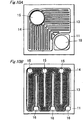
- Fig. 5A shows an example of cross section of the protrusion, in which case the side face of the protrusion includes two sloped surfaces having different angles of inclination ⁇ 1 and ⁇ 2 . Number of sloped surfaces is not limited to two, but may be larger. That is, angles of inclination are not limited to ⁇ 1 and ⁇ 2 , and n kinds of angles of inclination up to ⁇ n (n is an integer) may
- the protrusion formed on the substrate surface preferably has convex side face (that swells toward the outside) as shown in Fig. 5A and Fig. 15 .
- the inner surface of the recess protrudes toward the inside of the recess. This is because, for example in the case of a protrusion as shown in Fig. 17A and Fig.
- the semiconductor layer grown from the top of the protrusion and the layer grown from the valley between adjacent protrusions join in such a manner that decreases the inclination angle of the side face of the protrusion, so that the joint can be formed smoothly.
- the protruding (swelling) shape of the side face of the recess or the protrusion includes not only the beak-shaped protrusion such as shown in Fig. 5A but also convex curved surface as shown in Fig. 15 .
- the protruding (swelling) shape of the side face refers to such a shape as illustrated by a sectional view of Fig. 15 where the side face is on the outside of the straight line that connects the edge of the top face and the edge of the base (or, in the case of a recess, the side face is on the inside of the straight line that connects the edge of the surface that surrounds top opening and the edge of the bottom).
- cross section of the protrusion is wider than a normal trapezoid.
- cross section of the recess is narrower than a normal inverted trapezoid.
- a plurality of protruding portions may be provided on the side face of the protrusion or recess. It is preferable, however, that the side face of the recess or protrusion has a single protruding portion as shown in Fig. 5A and Fig. 15 , to ensure stable growth of semiconductor on the substrate.
- the recesses or protrusions are preferably formed with high density in order to achieve a high efficiency of extracting light. That is, it is preferable to form small recesses or protrusions at small intervals.
- the recesses or protrusions become smaller, it becomes difficult to form satisfactory recesses or protrusions due to the limitation of the machining accuracy, and notches are likely to be formed on the side face of the recesses or protrusions.
- the side face 21 of recess or protrusion has a constant angle of inclination as shown in Fig. 4B and Fig. 4C , notches 24 formed along the sloped side face 21 reach the top face 20 of the protrusion.
- two or more sloped surfaces 22, 23 of different angles of inclination are formed on the side face of the recess and/or protrusion as shown in Fig. 4A according to the present invention.
- the notches 24 generated in the lower sloped surface 22 are less likely to reach the top surface of the protrusion 20.
- notches down the slope are formed only on the lower first sloped surface among the first and second sloped surfaces 22, 23.
- the notches extend to reach the boundary of the second sloped surface 23, but do not extend into the second sloped surface. Consequently, the upper second sloped surface 23 is free from notches running along the slope, resulting in smaller roughness of the sloped surface.
- Abnormal morphology such as pits can be suppressed by growing semiconductor layer on the surface having such recess and/or protrusion. Forming the recess and/or protrusion on the substrate surface leads to no significant increase in dislocations formed in the semiconductor layer. This is supposedly because surface roughness of the upper sloped surface is made smaller than that of the lower sloped surface, and the circumference of the top surface of the protrusion is formed smoothly. The expression that "the circumference is formed smoothly" means that there are no substantial notches in the circumference.
- the protrusion or recess has curved side face
- the semiconductor growing from the valley between protrusions or from the bottom of a recess has smoother and smaller changes in the shape of the growing region, thus resulting in satisfactory growth.
- Notches formed on the side face of the recess or the protrusion can also be reduced by forming the protrusion or recess with curved side face.
- first sloped surface and a second sloped surface from the bottom of the substrate, on the side face of the protrusion with angle of inclination ⁇ 1 of the first sloped surface with respect to the bottom of the recess and/or protrusion and angle of inclination ⁇ 2 of the second sloped surface with respect to the bottom of the recess and/or protrusion satisfying the relation ⁇ 1 > ⁇ 2 .
- Propagation of notches generated on the side face of the protrusion from the first sloped surface to the second sloped surface can be prevented by such a constitution of the sloped surfaces.
- the first angle of inclination ⁇ 1 larger since it decreases the depth and size of the notches formed in the first sloped surface. The same applied to a case where recess is formed.
- first sloped surface 22 and a second sloped surface 23 from the bottom of the substrate, on the side face of the protrusion with surface roughness Ra 1 of the first sloped surface 22 and surface roughness Ra 2 of the second sloped surface 23 satisfying the relation Ra 1 > Ra 2 .
- Generation of voids and the like can be greatly reduced when growing the semiconductor by making the surface roughness Ra 2 of the second sloped surface smaller. It is supposed that generation of voids is suppressed because variations in the semiconductor growth rate between the protrusions are suppressed, and the junction between semiconductors is formed at constant point.
- the side face of the protrusion is formed from a single sloped surface as shown in Fig.
- surface roughness Ra 3 of the side face becomes larger than the surface roughness Ra 1 or Ra 2 of at least one of the sloped surfaces in the case of forming two sloped surfaces as described above. Moreover, since the large surface roughness continues to the top surface of the protrusion, occurrence of voids cannot be avoided even when the conditions of growing the semiconductor is controlled, thus resulting in lower output power.
- Surface roughness Ra 2 of the second sloped surface is preferably 0.1 ⁇ m or less, more preferably 0.01 ⁇ m or less and most preferably 0.005 ⁇ m or less.
- Either recess or protrusion may be formed on the substrate surface, and combination of recess and protrusion may also be formed. But it is preferable to form protrusions rather than recesses, since it makes it easier to grow the semiconductor layer without voids. When there are voids in the semiconductor layer around a recess or a protrusion, crystallinity of the semiconductor becomes lower and the function of recess or protrusion to scatter or diffract light is impeded, resulting in lower output power of the light emitting device. In order to prevent defects from growing in the semiconductor layer, it is preferable to make the second sloped surface provided on the side face of the recess and/or protrusion flat.
- the recess and/or protrusion have such a shape that is constituted from straight line segments which cross a plane substantially parallel to the stable growth plane of the semiconductor layer, as viewed from above the recess and/or protrusion.
- the "straight line segments which cross a plane substantially parallel to the stable growth plane as viewed from above the substrate” means straight lines that are not parallel to the intersect of the substrate surface and the stable growth plane and is inclined from the line of intersection.
- the stable growth plane refers to the facet surfaces formed as relatively smooth surfaces during the growth of semiconductor on the substrate.
- the stable growth plane generally appears as a facet in the course of growth.
- A-axis refers to the direction normal to the A plane. In case A-axis is inclined from the substrate surface, the angle from the projection of A-axis onto the substrate surface may be considered.
- Straight line that is not parallel to a plane parallel to A-axis refers to a straight line that is not parallel to A-axis or to the projection of A-axis onto the substrate surface.
- a plane that is parallel to a plane parallel to A-axis refers to a plane of which intersect with the substrate surface is a straight line that is parallel to A-axis or to the projection of A-axis onto the substrate surface.
- Configuration in plan view of the recess and/or protrusion viewed from above the substrate may be circle, triangle, parallelogram, hexagon or the like. Occurrence of pits and other defects can be suppressed by forming the recess or protrusion in polygons such as triangle, parallelogram or hexagon. More preferably, the recess or protrusion are formed in equilateral triangle, rhombus or equilateral hexagon. Occurrence of pits can be significantly suppressed and the second sloped surface can be easily formed when the recess or protrusion are formed in circles.
- protrusions namely increase the number of protrusions in a unit area, and increase the length and surface area of the side face, thereby increasing the effect of the protrusion to extract light and increasing the output power when it is used as a light emitting element.
- to form the recess or protrusion in polygon or circle means that they have polygonal or circular shape when viewed from above the substrate.
- the shape may not be exact polygon in geometrical meaning, and may be rounded at edges for the reason of manufacturing process.
- the recesses and/or protrusions are preferably formed in a repetitive pattern of the same shape, such as the pattern of a plurality of protrusions shown in Fig. 7 . While a single recess or protrusion may serve the purpose, the efficiency to scatter or diffract light can be improved and external quantum efficiency can be improved further by forming the recess and/or protrusion in a repetitive pattern.
- the recess and/or protrusion are formed in a repetitive pattern, occurrence of crystal defects due to the recess or protrusion can be suppressed by having at least the first and second sloped surfaces, more preferably by having a swelled side faces, further preferably by having curved and swelled side faces of protrusions or recesses, so entire surface of the substrate can be used as the light emitting surface.
- Depth of the recess or height of the protrusion is preferably 100 ⁇ or more, and more preferably in a range from 1000 to 10000 ⁇ .
- the wavelength of emitted light (206 nm to 632 nm in the case of a light emission layer made of AlGaInN-based material) denoted as ⁇
- the depth or height is at least ⁇ /4 or larger.
- the depth or height is preferably ⁇ /4n or larger, where n is the refractive index of the medium of propagation.
- Size of the recess and/or protrusion viewed from above the substrate, or length La of one of the sides that constitute the base of the recess and/or the protrusion is preferably at least ⁇ /4 or larger, where ⁇ is the wavelength of light emitted in the semiconductor (370 nm to 460 nm).
- ⁇ /4 translates into ⁇ /4n, where n is the refractive index of the semiconductor layer that serves as the medium of propagation for the emitted light.
- Length L b of one of the sides that constitute the top face of the recess and/or the protrusion is preferably 1.5 ⁇ m or larger. Forming the recess or the protrusion in such a size makes it possible to suppress the occurrence of voids coming up with semiconductor growth. It is more preferable to set the ratio L t /L b of length (L b ) of bottom of the recess and/or protrusion to length (L t ) of top surface of the recess and/or protrusion in a range of 1 ⁇ L c /L b ⁇ 2, and more preferably 1.1 ⁇ L t /L b ⁇ 1.8. This constitution makes it possible to suppress the occurrence of voids more effectively and increase the output power by as much as 10% or more.
- distance between the recesses or between the protrusions as viewed from above the substrate is preferably ⁇ /4 or larger, similarly to that described above.
- distance between the recesses or between the protrusions is preferably in a range from 0.5 ⁇ m to 5 ⁇ m inclusive, and more preferably from 1 ⁇ m to 3 ⁇ m inclusive.
- the distance between the recesses or between the protrusions refers to the minimum distance between adjacent recesses or protrusions.
- Cross sectional shape of the recess or protrusion is preferably trapezoid having side face that consists of two or more faces of different angles of inclination in the case of protrusion as shown in Fig. 5A , or a trapezoid having a curved side face that consists of first and second angles of inclination ⁇ 1 and ⁇ 2 as shown in Fig. 15 .
- it preferably has a shape of inverted trapezoid having a side face similar to that described above.
- Such a cross sectional shape makes it possible to further improve the efficiency of scattering or diffraction of light.
- the cross sectional shape of the recess or protrusion may not be exact trapezoid or inverted trapezoid in geometrical meaning, and may be rounded at edges for the reason of manufacturing process.
- first sloped surface and the second sloped surface in this order from the bottom of the substrate, are formed on the side face of the protrusion with angle of inclination ⁇ 1 of the first sloped surface with respect to the bottom of the recess and/or protrusion and angle of inclination ⁇ 2 of the second sloped surface with respect to the bottom of the recess and/or protrusion, output power due to scattering or diffraction is improved when angle of inclination ⁇ 1 is larger than 30° and smaller than 90°.
- angle of inclination 8 of the recess or protrusion is too large, the efficiency of scattering or diffraction decreases contrary to expectation, and pits are more likely to occur in the semiconductor layer.
- angle of inclination ⁇ 1 is preferably in a range from 45° to 80° inclusive, and preferably in a range from 50° to 70° inclusive.
- Angle of inclination ⁇ 2 is preferably in a range from 10° to 30° inclusive. Forming the recess or protrusion with angles in such ranges on the substrate surface enables it to suppress the occurrence of pits.
- Angle of inclination ⁇ 3 of the second sloped surface with respect to the top surface of the recess and/or protrusion is preferably 90° or larger.
- the inclination angle ⁇ m between the line connecting the edge of the bottom and the edge of the top face of the protrusion and the bottom plane of the protrusion is within a range from 20 to 80o, more preferably from 30 to 60o, as shown in Fig. 15 . If the inclination angle is too large, light reflecting surface (side face of the protrusion) occupies a smaller proportion of substrate surface, resulting in lower effect of extracting light. If the inclination angle is too small as shown in Fig.
- the semiconductor grown from the valley between adjacent protrusions join with the semiconductor grown from the top of the protrusion in such a manner as the former creeps below the latter in larger area, leading to the occurrence of defective growth and/or voids.
- the supplement of the inclination angle ⁇ m between the line connecting the edge of the bottom and the edge of the top face of the recess and the bottom plane of the recess is preferably within the range described above.
- the semiconductor formed on the substrate surface may be a semiconductor based on group III-V element or a semiconductor based on group II-VI element.
- Semiconductors based on group III-V elements include nitride semiconductors, among which GaN-based semiconductor, in particular, is preferably used.
- the stable growth plane of GaN-based semiconductor is generally M-plane ⁇ 1-100 ⁇ of hexagonal crystal system.
- the notation ⁇ 1-100 ⁇ represents all of (1-100), (01-10), (-1010), etc.
- M-plane is one of the planes that are parallel to A-axis in the substrate surface.
- Other planes that include A-axis of GaN semiconductor in the substrate surface, namely planes other than M-plane, such as the facet of ⁇ 1-101 ⁇ plane may also become the stable growth plane, depending on the growing condition.
- a sapphire substrate As for the substrate, a sapphire substrate, a Si substrate, a SiC substrate or a spinel substrate can be used.
- a sapphire substrate having a C plane (0001) as the principal plane can be used.
- the M-plane that is the stable growth plane of GaN-based semiconductor layer is the plane parallel to A plane ⁇ 11-20 ⁇ of the sapphire substrate.
- the A plane ⁇ 11-20 ⁇ represents all of (11-20), (1-210), (-2110), etc.
- nitride semiconductor When nitride semiconductor is grown on C plane of a sapphire substrate, for example, crystal growth begins at hexagonal spots enclosed by planes that include A-axis of the nitride semiconductor, like islands, and the islands eventually join with each other to form a homogeneous semiconductor layer. Therefore, it is preferable to form the recess or protrusion in such a planar configuration as a polygon (triangle, hexagon, etc.) that is constituted from sides which are perpendicular to straight lines connecting the center and vertices of an equilateral hexagon that is defined by A-axis of the nitride semiconductor as its sides.
- a polygon triangle, hexagon, etc.
- Side face of the recess and/or the protrusion is formed so as to comprise at least two sloped surfaces, in a protruding shape having two or more inclination angles or in a convex curved surface.
- the sapphire substrate having the recess or protrusion formed thereon allows it to grow nitride semiconductor having flat surface and high crystallinity on the surface thereof.
- the present invention when applied to a semiconductor light emitting device, can provide a light emitting device having high efficiency of extracting light.
- an ohmic electrode 14 formed on the light extracting surface of the semiconductor light emitting device may be formed on substantially the entire surface of the semiconductor layer 13 as shown in Fig. 8A and Fig. 8B , it is preferable to form the ohmic electrode in such a shape that has through holes 18.
- the efficiency of extracting light is greatly improved by the mutually enhancing effects of both features.
- the ohmic electrode formed on the p-type semiconductor may be made of an alloy that includes at least one kind selected from among a group consisting of Ni, Pd, Co, Fe, Ti, Cu, Rh, Ir, Au, Ru, V, W, Zr, Mo, Ta, Pt, Ag, oxide or nitride of these elements.
- Electrically conductive metal oxides (oxide semiconductors) such as indium tin oxide (ITO), ZnO, In 2 O 3 and SnO 2 may also be used.
- ITO indium tin oxide
- ZnO ZnO
- In 2 O 3 and SnO 2 may also be used.
- an alloy layer or a multi-layer film that includes one of the above can also be used.
- the translucent electrode is preferably made of ITO film in the visible light region.
- the reflective electrode is preferably made of Al, Ag or Rh for improving the efficiency of extracting light and other reason.
- the semiconductor device of the present invention has an effect of improving the crystallinity of the light emitting region (active layer) and increasing the output power by forming the recess or protrusion that scatters or diffracts light in the interface between the semiconductor layer and the substrate instead of the interface between the semiconductor layer and the electrode.
- light is scattered or diffracted by the recess and/or protrusion and is extracted efficiently upward from the semiconductor layer or downward from the substrate, resulting in greatly improved external quantum efficiency, in contrast to a flat substrate of the prior art in which light is transmitted laterally.
- intensity of light directed upward or downward from the substrate is increased by scattering or diffraction by the recess or protrusion, and accordingly luminance of the light emission surface of the light emitting device viewed squarely in front thereof (front brightness) is increased.
- Second, light transmitted along the semiconductor layer is decreased by the effect of scattering or diffraction by the recess or protrusion, thereby reducing the absorption loss due to the transmission, and increasing the optical output.
- the recesses and/or protrusions are formed to have a side face comprising two or more sloped surfaces, preferably with protruding curved surfaces on the substrate surface, so as to suppress the formation of notches on the side face of the recess and/or the protrusion ( Fig. 12, Fig. 13 ).
- the space surrounding the recess or protrusion can be completely filled with the semiconductor layer without causing voids.
- high external quantum efficiency is achieved and high output power can be maintained stably.
- the recess or the protrusion is formed in a circular shape, occurrence of pits can be greatly reduced. This improves the yield of production.
- the protrusions are formed by etching in two steps.
- a protective film 25 of a specified shape is formed as an etching mask on the substrate.
- the substrate is etched so as to form projections 20 (first step).
- the substrate is etched further so as to form the protrusions 20 having two sloped surfaces (second step).
- the protrusions are formed by etching in three steps.
- the protective film 25 of a specified shape is formed as an etching mask on the substrate.
- the substrate is etched so as to form the projections 20 as shown in Fig. 18B (first step).
- first step a part of the protective film 25 is etched to reduce the area thereof.
- second step etching is carried out by exposing at least part or whole of the top face 20t of the protrusion, the side face of the protrusion and the portion between the protrusions (in other words, recess).
- the inclination angle ⁇ m1 of the sloped surface of the protrusion 20 formed in the first step is larger than the inclination angle ⁇ m2 of the sloped surface of the protrusion 20 as a whole formed in the second step ( ⁇ m1 > ⁇ m2 ).
- the inclination angle ⁇ m2 of the sloped surface of the protrusion 20 as a whole formed in the second step means the inclination angle between the line connecting the edge of the bottom and the edge of the top face of the protrusion and the bottom face of the protrusion.
- Fig. 18E shows a partially enlarged view of boxed part by dotted line in Fig. 18C .
- V-shaped notch 27a is formed at the edge of the first sloped surface 22 of the larger inclination angle on the base, namely on the periphery of the valley 20b 2 between the protrusions (periphery of bottom 20b 2 of the recess, in the case of recess).
- notch is formed to extend along the first sloped surface 22 and the first sloped surface 22 has greater inclination angle than the second sloped surface 23, and therefore the joint of the first sloped surface 22 and the flat surface 20b2 of the substrate is etched with preference.
- etching is carried out while exposing at least part or whole of the top face 20t of the protrusion, the side face of the protrusion and the portion between the protrusions (in other words, recess) (third step).
- the curved surface 26 has the first inclination angle ⁇ 1 on the bottom face side and the second inclination angle ⁇ 2 on the top face side.
- Fig. 18F shows a partially enlarged view of boxed part by dotted line in Fig. 18D .
- notch 27a is formed on the periphery of the valley 20b 2 between the protrusions 20 in the second step.
- the notch 27a may lead to abnormal growth of the semiconductor.
- the notch 27a is smoothed into smooth notch 27b as shown in Fig. 18F .
- the abnormal growth of the semiconductor is suppressed.
- etching is carried out while exposing a part of the top face 20t of the protrusion, the side face of the protrusion and the portion between the protrusions after at least the first and second sloped surfaces 22, 23 have been formed on the side face of the protrusion 20, so as to form the side face of the protrusion 20 in a convex surface 26.
- the side face 26 of the protrusion 20 is preferably formed in such a configuration as the inclination angle ⁇ 2 on the top face side is smaller than the inclination angle ⁇ 1 on the bottom side ( ⁇ 1 > ⁇ 2 ).
- the inclination angle ⁇ m3 of the entire side face of the protrusion 20 smaller than the inclination angle ⁇ m2 of the sloped surface of the protrusion 20 formed after the second step ( ⁇ m2 > ⁇ m3 ), as shown in Fig. 18E and Fig. 18F .
- Making the inclination angle ⁇ m3 smaller is advantageous for making the notch 27a smoother.
- the inclination angle ⁇ m of the entire side face of the protrusion 20 can be made progressively smaller ( ⁇ m1 > ⁇ m2 > ⁇ m3 ) through the three etching steps of the first through third steps as described above.
- the inclination angle ⁇ 2 on the top face side becomes smaller than the inclination angle ⁇ 1 on the bottom side.
- Ratio of bottom length to the length of top face (L b1 /L t1 ) in the first process is preferably smaller than the ratio of lengths in the second process (L b2 /L t2 ) ((L b1 /L t1 ) ⁇ (L b2 /L t2 )).
- relationship ((L b2 /L t2 ) ⁇ (L b3 /L t3 )) preferably holds between the second step and the third step. This results in lager spacing between the top faces of the protrusions, so as to allow the satisfactory crystal growth of the semiconductor in the space between the protrusions, resulting in the better crystal growth of the semiconductor.
- the multi-step etching process described above achieves smooth side face of the recess or protrusion.
- rough side face 22a having notches formed thereon is likely to be formed because of the accuracies of etching and masking ( Fig. 4B, Fig. 4C ).
- the subsequent second step and third step of etching are carried out with at least a part of the top face 20t of the protrusion exposed, and therefore the notches 24 formed on the side face of the protrusion are smoothed.
- edge of the top face 20t of the protrusion 20 and corners of the notch 24 formed on the side face of the protrusion 20 are etched with preference. As a result, sharp edges are rounded as if chamfered.
- the second sloped surface 23 is formed on the side face of the protrusion 20 and, at the same time, the first sloped surface 22 is smoothed.
- the inclination angle ⁇ m of the entire side face of the protrusion also decreases.
- angular joint between the first sloped surface 22 and the second sloped surface 23 is rounded, and the notch 27a formed on the periphery of the base of the protrusion 20 in the second step is smoothed.
- timing of removing the protective film 25 can be selected as required. It is preferable to remove the protective film 25 simultaneously during the etching process to form the protrusion, since it eliminates the separate process of removing the protective film.
- the protective film 25 is left to remain in the first step, the remaining protective film 25 makes it easier to form the second sloped surface in the second etching step.
- the protective film 25 left to remain in the first step can also protect the top face 20t of the protrusion during the second step.
- the protective film 25 may be left to remain so as to be removed in the third etching step.
- the protective film may further be left to remain in the third step.
- the protective film may also be left in a shape that is suitable for the respective step in order to obtain a desired shape of protrusion or recess (particularly the side face shape).
- the side face of the protrusion 20 is formed preferably in a shape protruding (swelling) toward the outside as shown in Figs. 2D , 4A , 5A , 15 and 18C .
- the side face of the protrusion 20 is formed from the first sloped surface 22 on the bottom side and the second sloped surface 23 on the top face side. More preferably, such a side face 26 is formed that consists of the first sloped surface 22 and the second sloped surface 23 which are connected smoothly as shown in Fig. 18D .
- the plan-view configuration of the protrusion 20 may be selected as required, such as triangle, polygon, circle or the like.
- the plan-view configuration of the protrusion 20 has sharp corner, significant change in the shape can be caused during the multi-step etching operation, leading to significant variability in shapes of the protrusions among wafers or within a wafer, resulting in lower yield of production.
- the plan-view configuration of the protrusion 20 having sharp corner has disadvantage also with respect to crystal growth. That is, the nitride semiconductor grown on the top face 20t of the protrusion of the substrate has hexagonal crystal structure. In case the plan-view configuration of the protrusion is triangle as shown in Fig.
- gap is produced between the hexagonal semiconductor crystal and the triangular top face of the protrusion, thus making the semiconductor crystal likely to grow unevenly. Uneven growth of the semiconductor crystal increases the chance of abnormal growth such as pits when islands of semiconductor crystal join with each other to form a layer.
- the plan-view configuration of the protrusion is circle as shown in Figs. 19A through 19C , on the other hand, gap between the hexagonal semiconductor crystal and the edge of the top face of the protrusion becomes smaller, thus making segregation of the semiconductor crystal less likely to occur. As a result, the semiconductor can be grown with abnormal growth such as pits being suppressed. Therefore, it is preferable that the plan-view configuration of the protrusion 20 (particularly the top face) does not have sharp corners.
- the shape is, for example, a polygon having vertices of right angles or obtuse angle (for example, polygon having four or more vertices), preferably a polygon having rounded vertices, more preferably ellipse, and most preferably circle.
- Figs. 19A through 19D show examples of arrangement of protrusions.
- the arrangement of the protrusions is preferably as follows.
- a circle 31 sandwiched between adjacent protrusions 20 and is circumscribed with the base of the protrusion 20 is referred to as the first circle.
- a circle 32 that is circumscribed with the periphery of the bases of at least three protrusions 20, and preferably has the largest diameter in the region between the protrusions 20 is referred to as the second circle. Diameter of the second circle 32 is larger than that of the first circle 31.
- a circle 33 sandwiched between adjacent protrusions 20 and is circumscribed with the peripheries of the top faces of the protrusions 20 is referred to as the third circle.
- the protrusions 20 are preferably arranged so that diameter of the third circle 33 becomes larger than that of the second circle 32.
- circles of which diameters are the shortest line segments that connect the bases of two protrusions 20 are referred to as the first circle 31, and the shortest line segments that connect the bases of two top faces are referred to as the third circle 33.
- the second circle 32 In a region surrounded by three protrusions 20, a circle that is circumscribed with the periphery of the bases of the three protrusions 20, and has the largest diameter in the region between the protrusions is taken as the second circle 32.
- Diameters of the first circle R 1 , the second circle R 2 and the third circle R 3 satisfy the relation R 3 > R 2 > R 1 . Crystal quality will be better when this relation is satisfied.
- Fig. 19B shows semiconductor crystal grown to a height halfway up the protrusion 20 on a substrate 10 of Fig. 19A .
- Semiconductor crystal 42 grown from the region between the protrusions 20 and semiconductor crystal 41 grown from the top face 20t of the protrusion are shown.
- the islands of crystal 41 on the top faces of the protrusion grows in the direction of thickness and in the lateral direction as well so as to approach each other. Therefore, the islands of semiconductor crystal 41 growing from the top faces of the protrusions eventually join with each other as the growth proceeds, as indicated by growth prediction circles of dashed lines in Fig. 19D .
- the semiconductor crystal 42 growing from the region between the protrusions 20 grows in the direction of thickness. If the islands of semiconductor crystal 41 growing from the top faces of the protrusions join with each other before thickness of the semiconductor crystal 42 reaches the height of the protrusion, voids are generated. Therefore, occurrence of voids can be suppressed by increasing the distance between protrusions 20. However, in order to ensure the effect of the substrate with recess/protrusion to extract light, it is preferable to dispose the protrusions 20 as dense as possible. Therefore, it is advantageous to prevent voids and other crystalline defects from occurring while increasing the density of the protrusions.
- the protrusions having inclined side faces are provided.
- surface area of the semiconductor crystal 42 growing from the region between the protrusions increases as thickness thereof increases.
- the area surrounded by the top faces of the protrusions increases.
- the two conditions described above high density of protrusions and large distance between protrusions
- the semiconductor crystal 41 grown from the top face of the protrusion and the semiconductor crystal 42 grown from the region between the protrusions grow favorably, and it is made possible to prevent the occurrence of abnormal growth and voids.
- Fig. 17A and 17B are schematic sectional views showing the semiconductor crystal grown halfway up the protrusion 20 on the substrate, showing a part of the cross section of Fig. 19B .
- the crystal 41 grown on the top face 20t of the protrusion is indicated with hexagon, in order to illustrate the typical form of nitride semiconductor.
- the present invention can be applied to a case where the crystal grows in other form.
- the present invention can be preferably applied to a system where the crystal grows relatively isotropically.
- Fig. 19C shows a case where the protrusions are disposed in an arrangement different from that of Fig. 19A .
- Fig. 19C shows the semiconductor crystal that has been grown halfway up the protrusion 20, similarly to Fig. 19B .
- axes 51 and 52 that connect the centers of adjacent protrusions 20 intersect with each other at about 60o, while the protrusions are located at substantially equal spacing on vertices of equilateral triangles.
- Arrangement of the protrusions in Fig. 19B is a periodically repeated pattern of parallelogram (dashed line 53 in the drawing) as a unit in the directions of the axes 51, 52.
- Fig. 19C shows a case where the protrusions are disposed in an arrangement different from that of Fig. 19A .
- Fig. 19C shows the semiconductor crystal that has been grown halfway up the protrusion 20, similarly to Fig. 19B .
- axes 51 and 52 that connect the centers of adjacent protrusions 20 intersect with each
- axes 51 and 52 that connect the centers of adjacent protrusions 20 intersect with each other perpendicularly, while the protrusions are located at substantially equal spacing on vertices of squares.
- Arrangement of the protrusions in Fig. 19C is a periodically repeated pattern of square (dashed line 53 in the drawing) as a unit in the directions of the axes 51, 52.
- Fig. 19C when circles of which diameters are the shortest line segments that connect the bases and top faces of two protrusions 20 are taken as the first circle 31 and the third circle 33, respectively, the first circle 31 and the third circle 33 are concentric with the center located at the middle point of the line segment that connects the centers of the two protrusions.
- the circle (the second circle 32) that has the largest diameter in the region between the protrusions is a circle that is circumscribed with the periphery of the bases of four protrusions.
- the protrusions may also be arranged so as to satisfy the relation R 3 > R 2 > R 1 . This improves a quality of crystal growth.
- Fig. 19B(A) and Fig. 19C have common features as follows. First, consider perpendicular bisector of the line segment that connects the centers of the two protrusions 20 that are circumscribed with the second circle 32 having the largest diameter. Then the centers of the first, second and third circles lie on the perpendicular bisector. Second, the second circle 32 intersects with the third circle 33 that is interposed by the protrusions 20 that are circumscribed with the second circle 32.
- An arrangement having these two features are preferable because it cause favorable changes in the area and in shape of the crystal 42 growing from the region between the protrusions in the course of growth, thus enabling it to obtain light emitting element having excellent crystallinity.
- Fig. 19D shows an example where the protrusions 20 having triangular shape in plan view are arranged.
- axes 51 and 52 of the periodical structure of protrusions intersect with each other at about 120o.
- Unit of the periodical structure is a rhombic cell indicated by dashed line 43.
- the sides that constitute the protrusion 20 are parallel to the sides that constitute the adjacent protrusions 20, with narrow paths formed between adjacent sides.
- the second circle 32 and the third circle 33 are spaced from each other.
- the first through third circles in overlapping relationship are selected as follows. First, of the plurality of protrusions that are circumscribed with the second circle, two adjacent ones are selected and the first circle and the third circle interposed by the two protrusions are considered. For the first circle 31 and the third circle 33, those which are located furthest from the adjacent second circle 32 (in Fig. 19D , the second circles 32 located at both ends of the side of the triangle) are taken. In Fig. 19D , for example, the first circle 31 and the third circle 33 having centers located on the line segment that connects the middle points of the sides of the protrusion. The same overlapping configuration applies also to the cases of Fig. 19A and Fig. 19C .
- the islands of semiconductor crystal 41 growing from the top faces of the protrusions may join with each other before the semiconductor crystal 42 growing from the region between the protrusions reaches the top face of the protrusion. If this happens, voids likely to occur in the region 44 enclosed by dashed line in Fig. 19D .
- Crystallinity of the semiconductor that grows on the substrate having recess and/or protrusion depends also on the arrangement of the protrusions (or recesses) on the substrate surface. It is preferable to set the plan-view configuration and arrangement of the protrusions so that narrow path is not formed between the protrusions as shown in Fig. 19A , 19C .
- undesirable light propagation in the light emitting device can be suppressed by forming recesses and/or protrusions in the substrate surface, which results in an improved light extracting efficiency. Also, occurrence of pits or voids due to the recesses and/or protrusions can be suppressed. Therefore, a high-performance semiconductor device can be provided.
- Fig. 1 shows a preferred embodiment of the semiconductor device according to the present invention, wherein an n-type semiconductor layer 11, an active layer 12 and a p-type semiconductor layer 13 are formed successively on a substrate 10.
- the substrate 10 has protrusions 20 formed in a repetitive pattern in the surface thereof.
- Height of the protrusion 20 is preferably in a range from 0.1 ⁇ m to 2 ⁇ m inclusive.
- Length "a" of one side of the protrusion 20 if it is a polygon, or diameter of the protrusion if it is circle is preferably in a range from 1 ⁇ m to 10 ⁇ m inclusive.
- Distance between adjacent protrusions 20 is preferably in a range from 1 ⁇ m to 10 ⁇ m inclusive.
- a protective film 25 is formed as an etching mask on the substrate 10.
- the substrate 10 may be made of sapphire, Si, SiC or the like.
- the protective film 25 is formed into a pattern.
- the pattern of the protective film 25 in plan view may be, for example, as shown in Figs. 7A through 7H (hatching in Figs. 7A through 7H indicates the region where the protective film is formed).
- Figs. 7A through 7D show examples of the protective film when protrusions are formed on the substrate.
- the protective film may be formed in the patterns shown in Figs. 7E through 7H .
- the recesses or the protrusions are formed in circular or polygonal shape, it is preferable to arrange them in a hexagonal pattern in order to reduce pits.
- the protective film is formed in a circular pattern as shown in Fig. 7A .
- etching is preferable. Specifically, gas phase etching, plasma etching, reactive plasma etching (such as RIE, magnetron RIE), ECR plasma etching, sputter etching, ion beam etching and photo-etching. Reactive ion etching (RIE), above all, is preferably used.
- RIE reactive ion etching
- etching gas Cl 2 compound or F compound such as Cl 2 , SiCl 4 , BCl 3 , HBr, SF 6 , CHF 3 , C 4 F 8 or CF 4 can be used.
- An inert gas such as Ar may also be used.
- a gas having high selective etching capability for the substrate and the mask is preferably used, such as a mixture gas of SiCl 4 and Cl 2 , in the case of sapphire substrate and mask made of SiO 2 .
- a gas having selectivity different from that of the second step preferably a gas having lower selectivity is used, such as CF 4 , CHF 3 or Ar can be used.
- the protrusions 20 having two sloped surfaces may also be formed by continuing the etching still after the protective film has been completely removed in the process shown in Fig. 2C .
- the protrusions 20 having two sloped surfaces may also be formed by changing the etching rate or apparatus amid the course.
- Recesses having two sloped surfaces may be formed by changing the etching rate or other method. For example, after etching the substrate to some extent, etching may be continued with a slower etching rate, so as to form recesses having two sloped surfaces.
- the n-type semiconductor layer 11, the active layer 12 and the p-type semiconductor layer 13 are formed successively one on another in this order on the substrate 10 whereon the protrusions 20 are formed in an ordered pattern.
- a semiconductor including GaN semiconductor
- growth of a semiconductor, including GaN semiconductor, on a substrate is significantly affected by the surface condition of the substrate.
- the side face (sloped surface) of the protrusion is formed in one step as shown in Fig. 5B
- significant notches are formed on the side face of the protrusion along the slope as shown in the SEM photograph of Fig. 14 .
- This situation is schematically shown in Fig. 4B and Fig. 4C .
- Presence of the notches increases the possibility of voids to be generated when growing the semiconductor. This is because not only the surface roughness of the side face is different between adjacent protrusions 20, but also there is significant difference in the surface roughness within a single protrusion.
- semiconductor grows at different rates near the side face of the protrusion, fast at one point and slowly at another, so that the semiconductor grown at the fast growing point spreads over the slow growing point. As a result, voids can easily develop in the semiconductor.
- the side face (sloped surface) of the protrusion is formed in two steps as shown in Fig. 5A . Therefore, while the first sloped surface near the substrate includes some notches, the second sloped surface located above is almost free from notches, as shown in Fig. 12 .
- Fig. 4A is a perspective view showing the protrusion 20 schematically.
- the first sloped surface 22 and the second sloped surface 23 are formed in this order from the bottom of the substrate.
- the first sloped surface 22 includes some notches 24, the second sloped surface 23 is almost free from notches.
- generation of voids is suppressed by the second sloped surface 23 that is free from notches.
- the device forming process is carried out with electrode formed, so as to finish the LED chip. Holes and electrons are injected from the n-type semiconductor layer 11 and the p-type semiconductor layer 13 into the active layer 12, where both charges recombine thereby to emit light. The light is extracted through the sapphire substrate 10 or the electrode formed on the p-type semiconductor layer 13.
- the protrusions 20 are formed on the surface of the substrate 10 as shown in Fig. 3B or Fig. 3C , light that is incident on the interface between the p-type semiconductor layer 13 and the electrode or on the interface between the n-type semiconductor layer 11 and the substrate 10 with an angle of incidence equal to or larger than the critical angle is scattered or diffracted. Most of the scattered or diffracted light is incident on the interface between the p-type semiconductor layer 13 and the electrode or on the interface between the n-type semiconductor layer 11 and the substrate 10 with an angle of incidence smaller than the critical angle, and can be extracted to the outside.
- the side face of the protrusion 20 is formed from a sloped surface with a single angle of inclination as shown in Fig. 3B or Fig.
- voids are likely to be generated in the semiconductor layer 11.
- crystallinity of the semiconductor becomes lower and the quantum efficiency decreases.
- side face of the protrusion is formed from two sloped surfaces of different angles of inclination so as to suppress the generation of voids, as shown in Fig. 3D .
- This constitution makes it possible to efficiently extract light that has been generated in the active layer and improve the crystallinity of the semiconductor, thereby providing a semiconductor device of higher output power.
- the contact electrode provided on the p-type semiconductor layer 13 is a transparent electrode
- the device is mounted face up but, in the case of reflecting electrode, the device is mounted face down.
- the present invention is effective in either mode of mounting. Even in the case of reflective electrode, the device can be mounted face up when the electrode has opening or notch. In this case, too, the present invention achieves conspicuous effect.
- the protrusion 20 has a circular shape in plan view, although the protrusion 20 may also be formed in a polygonal shape.
- the substrate 10 is made of sapphire and the semiconductor 11 is made of GaN
- the GaN grows with an offset angle of 30 degrees from the lattice of the sapphire substrate. Therefore, it is preferable to form the protrusion 20 on the sapphire substrate 10 in such a shape as follows.
- Shape of the protrusion 20 in plan view is formed in a polygon that has sides substantially parallel to A planes (11-20), (1-210) and (-2110) of GaN and vertices in stable growth planes (1-100), (01-10) and (-1010) of GaN.
- This polygon does not have any side that is parallel to the stable growth planes (1-100), (01-10) and (-1010) of GaN, namely M-plane.
- the protrusion 20 has a shape of equilateral triangle in plan view
- the protrusion 20 may also be formed in an equilateral hexagonal shape.
- the equilateral hexagonal shape may be arranged in direction shown in either Fig. 11A or Fig. 11B .
- GaN is grown on C plane of the sapphire substrate as described previously, A plane of the sapphire substrate and M-plane of GaN become parallel to each other. Therefore, it is preferable to arrange the recess or protrusion of equilateral hexagon as shown in Fig.
- the sides that constitute the equilateral hexagon cross at right angles to one of the M-planes that are stable growth plane of GaN, when viewed from above the substrate.
- this means that the equilateral hexagon is formed from sides that are perpendicular to the straight lines that connect the center and vertices of an equilateral hexagon that is defined by M-planes of GaN as its sides, when viewed from above the substrate.
- the side face of the protrusion consists of at least two sloped surfaces (first sloped surface 22, second sloped surface 23) as shown in Fig. 4A and Fig. 5A .
- the inclination angle ⁇ 2 on the top face side of the protrusion is smaller than the inclination angle ⁇ 1 on the bottom side.
- the inclination angle ⁇ is the angle between the side face and the bottom of the protrusion.
- inner wall of the recess is also formed so that the inclination angle ⁇ 2 of the upper inner wall is larger than the inclination angle ⁇ 1 of the lower inner wall.
- the inclination angle ⁇ 1 of the inner wall is the complementary angle of the angle ⁇ i between the inner wall and the bottom surface of the recess.
- the angle ⁇ 2 between the upper inner wall and the bottom surface of the recess is nearly equal to the inclination angle ⁇ 3 of the protrusion.
- the first sloped surface 22 and the second sloped surface 23 are located at the top and bottom of the protrusion and/or the recess, respectively. This makes manufacturing easier, causes the semiconductor layer to grow favorably to near the protrusion and enables it to suppress the occurrence of pit and voids.
- side face of the protrusion is formed in a curved surface.
- radius of curvature may be made larger on the top face side and smaller on the bottom side.
- such a configuration may also be employed as the bottom side is flat, i.e., upper side of the side face is curved and the lower side is flat.
- a plurality of curved portions and a plurality of flat portions may be formed on the side face of the protrusion.
- the second sloped surface may be formed in a curved surface with the first sloped surface consisting of substantially flat surface.
- Condition of the side face may be selected as required in accordance to the substrate material, etching condition, material of the semiconductor layer and other factors.
- ⁇ 2 on the top face side of the protrusion smaller than the inclination angle ⁇ 1 on the bottom side, as shown in Fig. 15 .
- This configuration makes the changes in the shape and surface area of the semiconductor layer growing on the substrate smoother. That is, better crystal can be grown while suppressing the occurrence of abnormal crystal growth.
- the inclination angle ⁇ m can be decreased when the side face is formed in a single curved surface rather than having a partially curved portion or a plurality of curved surfaces. If the inclination angle ⁇ m can be decreased, ratio of the area of the side face to the area of the substrate surface can be increased so as to achieve higher efficiency of extracting light.
- the substrate used to grow the nitride semiconductor thereon may be made of an insulating material such as sapphire or spinel (MgAl 2 O 4 ) having principal plane in C plane, R plane or A plane, or an oxide such as lithium niobate or neodymium gallate that forms lattice junction with silicon carbide (6H, 4H, 3C), silicon, ZnS, ZnO, Si, GaAs, diamond, or oxide substrates such as lithium niobate or neodymium gallate which can provide a good lattice match with nitride semiconductor.
- an insulating material such as sapphire or spinel (MgAl 2 O 4 ) having principal plane in C plane, R plane or A plane, or an oxide such as lithium niobate or neodymium gallate that forms lattice junction with silicon carbide (6H, 4H, 3C), silicon, ZnS, ZnO, Si, GaAs, diamond, or oxide substrate
- a substrate made of nitride semiconductor such as GaN or AlN may also be used provided that it is thick enough to form devices thereon (over several tens of micrometers).
- a substrate made of different material may be cut with offset angle. If C plane of sapphire is used, offset angle is preferably in a range from 0.01° to 3.0°, and more preferably from 0.05° to 0.5°.
- the semiconductor light emitting device may have such a structure as electrodes of different types of electrical conductivity are provided on the same side of the substrate as shown in Fig. 6 , Fig. 25A and Fig. 25B .
- An electrically conductive substrate may also be used with electrodes for first conductivity type layer and second conductivity type layer provided on opposite sides of the substrate, respectively.
- nitride semiconductor In case nitride semiconductor is used as the semiconductor, it is preferable to use nitride semiconductor having composition represented by general formula In x Al y Ga 1-x-y N (0 ⁇ x, 0 ⁇ y, x + y ⁇ 1). B, P or As may be included in the nitride semiconductor as mixed crystal.
- the n-type nitride semiconductor 11 and the p-type nitride semiconductor 13 may be formed in either single layer or multi-layer structure.
- the nitride semiconductor is doped with n-type impurity or p-type impurity.
- n-type impurity group IV elements or group VI element such as Si, Ge, Sn, S, O, Ti, Zr may be used and preferably Si, Ge or Sn are used and more preferably Si is used. While there is no restriction, on the p-type impurity, Be, Zn, Mn, Cr, Mg or Ca may be used and Mg is preferably used. Thus both types of nitride semiconductor can be formed.
- the active layer 12 is preferably formed in single quantum well (SQW) structure or multiple quantum well (MQW) structure.
- the embodiments shown in Fig. 6 and Fig. 25 have such a structure as the light emitting element 101 is formed on the substrate 10, with electrodes 16, 14 provided on the layers 11, 13 of different conductivity types, respectively, of the light emitting element. While the device structure made by stacking the p-type layer 13 and the n-type layer 11 in a particular order is described as an example in this specification, the order of stacking the layer is not restricted to that described in the specification.
- the light emitting device may have any proper structure as long as it has at least the layer of first conductivity type 11 and the layer of second conductivity type 13. More preferably, the active layer 12 is provided between the layer of first conductivity type 11 and the layer of second conductivity type 13. Alternatively, a base layer 11a that provides a base for the element structure 101 may be formed between the substrate 10 and the n-type layer 11b of the layer of first conductivity type as shown in Fig. 25B .
- the buffer layer is preferably made of a nitride semiconductor represented by general formula Al a Ga 1-a N (0 ⁇ a ⁇ 0.8), more preferably a nitride semiconductor represented by general formula Al a Ga 1-a N (0 ⁇ a ⁇ 0.5). Thickness of the buffer layer is preferably in a range from 0.002 to 0.5 ⁇ m, more preferably from 0.005 to 0.2 ⁇ m, and most preferably 0.01 to 0.02 ⁇ m.
- Semiconductor layers of better crystallinity can be formed on the substrate by making the thickness of the buffer layer smaller than the height of the protrusion (or depth of the recess) of the substrate.
- the semiconductor layer of satisfactory crystal structure can be made with less voids, pits and dislocations.
- the buffer layer is grown at a temperature preferably in a range from 200 to 900°C, and more preferably from 400 to 800°C. This makes it possible to reduce dislocations and pits generated on the nitride semiconductor.
- An Al x Ga 1-x N (0 ⁇ x ⁇ 1) layer may also be formed by ELO (epitaxial lateral overgrowth) method on the substrate made of different material.
- the ELO (epitaxial lateral overgrowth) method is a process of growing nitride semiconductor in lateral direction so as to bend and converge threading dislocation and decrease dislocations.
- the buffer layer may be formed in multiple layer structure, such that includes a low-temperature growth layer and a high-temperature growth layer.
- the high-temperature growth layer may be a GaN layer grown without doping or one that is doped with an n-type impurity. Thickness of the high-temperature growth layer is preferably 1 ⁇ m or larger, and more preferably 3 ⁇ m or larger.
- the high-temperature growth layer is grown at a temperature preferably in a range from 900 to 1100°C, and more preferably at 1050°C or higher.
- the n-type semiconductor layer 11 is grown.
- an n-type contact layer is grown.
- the n-type contact layer has such a composition that has band gap energy larger than that of the active layer, preferably Al j Ga 1-j N (0 ⁇ j ⁇ 0.3). While there is no limitation to the thickness of the n-type contact layer, it is preferably 1 ⁇ m or larger, and more preferably 3 ⁇ m or larger.
- an n-type cladding layer is grown.
- the n-type cladding layer includes Al.
- the concentration of the n-type impurity is preferably in a range from 1 ⁇ 10 17 to 1 ⁇ 10 20 /cm 3 , more preferably from 1 ⁇ 10 18 to 1 ⁇ 10 19 /cm 3 .
- the n-type impurity may also be included with graded concentration.
- the cladding layer can also perform a better function of carrier confinement.
- the active layer 12 used in the present invention is preferably formed in such a quantum well structure that consists of at least a well layer having composition of Al a In b Ga 1-a-b N (0 ⁇ a ⁇ 1, 0 ⁇ b ⁇ 1, a + b ⁇ 1) and a barrier layer having composition of Al c In d Ga 1-c-d N (0 ⁇ c ⁇ 1, 0 ⁇ d ⁇ 1, c + d ⁇ 1).
- Output power of the light emitting device can be made higher by forming the active layer from nitride semiconductor without doping or while doping with an n-type impurity.
- the well layer is grown without doping and the barrier layer is grown while doping with an n-type impurity in order to increase the output power and light emission efficiency of the light emitting device.
- Al is included in the well layer of the light emitting device, it is made possible to emit light in a wavelength region where it is difficult to emit light with the conventional well layer made of InGaN, namely wavelengths near 365 nm, that corresponds to the band gap energy of GaN, and shorter.
- Thickness of the well layer is preferably in a range from 1 nm to 30 nm inclusive, more preferably from 2 nm to 20 nm inclusive and most preferably from 3.5 nm to 20 nm inclusive.
- the layer cannot satisfactorily function as the well layer.
- the thickness is 2 nm or more, relatively homogeneous layer can be obtained without fluctuation in thickness.
- the thickness is 3.5 nm or more, output power can be increased further. This is because a thicker well layer allows for injection of more carriers so as to emit light with high efficiency and high internal quantum efficiency through recombination of carriers as in an LD driven with a high current, and this effect is remarkable particularly in a multiple quantum well structure.
- the effect of increasing the output power similarly to the above can be achieved by setting the thickness to 5 nm or more.
- the well layer is thicker than 30 nm, on the other hand, crystallinity of quaternary mixed crystal of InAlGaN becomes lower, resulting in lower performance of the device.
- the thickness of the well layer is set to 20 nm or less, it is made possible to grow the crystal while suppressing the occurrence of crystal defects.
- the thicker the layers that constitute the active layer the thicker the active layer and higher the value of Vf becomes.
- the barrier layer is preferably doped with an n-type impurity or undoped.
- concentration of the n-type impurity is preferably 5 x 10 16 /cm 3 or higher.
- the concentration is preferably in a range from 5 ⁇ 10 16 to 2 ⁇ 10 18 /cm 3 .
- the impurity concentration is preferably in a range from 5 ⁇ 10 17 to 1 ⁇ 10 20 /cm 3 , and more preferably in a range from 1 ⁇ 10 18 to 5 ⁇ 10 19 /cm 3 .
- the well layer either does not substantially include n-type impurity or is undoped.
- the barrier layer is doped with an n-type impurity, either all barrier layers in the active layer may be doped, or some of the barrier layers may be doped while leaving the others undoped. In case only some of the barrier layers are doped with n-type impurity, it is preferable to dope the barrier layers that are located on the n-type layer side in the active layer.
- the nth barrier layer Bn (n is a positive integer) from the n-type layer side is doped, for example, preferably the first through nth barrier layers are all doped with impurity, such a light emitting device can be made as electrons are efficiently injected into the active layer so as to achieve high efficiency of light emission and high internal quantum efficiency.
- the well layer too, an effect similar to that of the barrier layer can be achieved by doping the mth well layer Wm (m is a positive integer) from the n-type layer side. Similar effect can also be achieved by doping both the barrier layer and the well layer.
- the p-type cladding layer while there are no limitations to the composition as long as it has band gap energy larger than that of the active layer so as to be capable of confining the carrier within the active layer, the composition is preferably Al k Ga 1-k N (0 ⁇ k ⁇ 1), and more preferably Al k Ga 1-k N (0 ⁇ k ⁇ 0.4). While there is no limitation to the thickness of the p-type cladding layer, it is preferably in a range from 0.01 to 0.3 ⁇ m, and more preferably from 0.04 to 0.2 ⁇ m.
- Concentration of the p-type impurity is preferably in a range from 1 ⁇ 10 18 to 1 ⁇ 10 21 /cm 3 , more preferably from 1 ⁇ 10 19 to 5 ⁇ 10 20 /cm 3 .
- the p-type impurity in the range described above enables it to decrease the bulk resistivity without deteriorating the crystallinity.
- the p-type cladding layer may be formed either in single layer structure or multiple layer structure (super lattice structure). In the case of multiple layer structure, it may comprises a layer represented by Al k Ga 1-k N described above and other nitride semiconductor layers having a band gap energy smaller than that of the former.
- the layer of smaller band gap energy have a composition represented by In 1 Ga 1-1 N (0 ⁇ 1 ⁇ 1) or Al m Ga 1-m N (0 ⁇ m ⁇ 1), similarly to the case of the n-type cladding layer. Thickness of each layer constituting the multiple layer structure in the case of super lattice structure is preferably 100 A or less, more preferably 70 A or less and most preferably in a range from 10 to 40 A.
- the p-type impurity may be added to at least either the layers having larger band gap energy or the layers having smaller band gap energy. When both the layers having larger band gap energy and the layers having smaller band gap energy are doped, the doses may be the same or different.
- the p-type contact layer is preferably formed in composition of Al f Ga 1-f N (0 ⁇ f ⁇ 1), and more preferably Al f Ga 1-f N (0 ⁇ f ⁇ 0.3) which enables it to achieve good ohmic contact with the p electrode 14 that is an ohmic electrode.
- Concentration of the p-type impurity is preferably 1 ⁇ 10 17 /cm 3 or higher. It is preferable that the p-type contact layer has such a graded composition as the p-type impurity concentration is higher and mix proportion of Al is lower on the electrically conductive substrate side. In this case, the composition may be graded either continuously or stepwise.
- the p-type contact layer may be constituted from a first p-type contact layer that makes contact with the ohmic electrode and has high p-type impurity concentration and low Al content, and a second p-type contact layer that has low p-type impurity concentration and high Al content.
- the first p-type contact layer enables it to achieve good ohmic contact and the second p-type contact layer suppresses self-absorption of the emitted light.
- the wafer is taken out of a reaction apparatus and is subjected to heat treatment at 400°C or higher in an atmosphere that includes oxygen and/or nitrogen. This process removes hydrogen that is bonded in the p-type layer, so as to form the p-type nitride semiconductor layers that show p-type conductivity.
- the p-type electrode 14 that achieves ohmic contact is formed on the surface of the p-type contact layer.
- the p-type electrode may be formed by CVD process, sputtering, vapor deposition or the like.
- the p-type electrode is preferably formed from the material described previously. Sheet resistance can be decreased by forming in multiple layer structure of two or more layers with the total thickness of 50000 A or less, compared with a singular layer structure having a uniform thickness.
- the p-type electrode may be formed in various shapes such as rectangular, stripes, square or lattice in plan view.
- the p-type electrode 14 may be formed over the entire surface of the p-type semiconductor layer, then openings 18 are formed in dots as shown in Fig. 8A and Fig. 8B .
- the p-type electrode may also be formed in such shapes as rhombic, parallelogram, mesh, stripes or comb as shown in Fig. 8C and Fig. 8D.
- a branching shape such that a single stem branches into a plurality of portions as shown in Fig. 9A and Fig. 10A may also be employed.
- Plurality of branch electrodes that are electrically connected may be formed in stripes while the p-type electrode has openings 18 as shown in Fig. 9C and Fig. 10B .
- circular pattern may be employed.
- area S of the portion surrounded by the outermost periphery of the p electrode (total area of the electrode including the openings) and total length L of the circumference of the openings preferably satisfy a relation L/S ⁇ 0.024 ⁇ m/ ⁇ m 2 . This enables it to make a semiconductor light emitting device that allows efficient emission of light from the surface of the p-type semiconductor layer and has a low value of Vf.
- the plurality of openings preferably have substantially identical shapes, which makes it easier to form the openings and achieves uniform light emission in the surface. It is also preferable that each of the plurality of openings has substantially the same area, which also contributes to achieving uniform light emission in the surface.
- the p electrode 14 is an ohmic electrode used for supplying current to the device through ohmic contact with the surface of the p-type nitride semiconductor layer 13.
- a p pad electrode 15 for connection by wire bonding, besides the p electrode 14 for ohmic contact, and connect the p pad electrode 15 and the p electrode 14 that is an ohmic electrode.
- the p pad electrode 15 may be either provided on the p-side layer 13, or provided outside of the p-side layer 13 with metal wiring, for example, via an insulating film on the n-type layer 11 whereon the n-type electrode 16 is formed.
- the p pad electrode 15 When the p pad electrode 15 is formed on the p-side layer 13, the p pad electrode 15 may partially overlap the p electrode 14, or the p pad electrode 15 may be formed on the p electrode 14. Since the p pad electrode 15 is provided for the purpose of packaging with wires, it may have any thickness as long as it does not damage the semiconductor device when mounting. In case light is extracted from the side where the p-type electrode 15 is formed, it is necessary to form the p-type electrode 15 as small as possible.
- the p-type electrode 15 is preferably made of a material that bonds well. Specifically, Co, Fe, Rh, Ru, Ti, V, Cr, Zr, Nb, Mo, Hf, Ta, W, Re, Mn, Al, Zn, Pt, Au, Ru, Pd or Rh may be used. Preferably, at least one kind selected from among a group consisting of Ag, Al, Pt, Cu, Ni, Ti, Au and Rh and oxide, nitride and the like thereof are used. More preferably, at least one kind selected from among a group consisting of Ag, Al and Pt is used.
- the p pad electrode may be made in single layer, alloy or multiple layers.
- the n electrode 16 is formed on the surface of the n-type contact layer.
- W/Al, Ti/Al, Ti/Al/Ni/Au, W/Al/W/Pt/Au or Al/Pt/Au or the like may be used. Thickness of the n electrode 16 is preferably in a range from 0.1 to 1.5 ⁇ m.
- the n electrode 16 serves as a pad electrode for bonding as well as making ohmic contact.
- the n electrode 16 may also be formed in two layers of a pad electrode for bonding and an ohmic electrode that makes ohmic contact with the n-side layer 11, which may be formed at the same time in substantially the same shape.
- the n electrode for ohmic contact and the n pad electrode may also be formed one on another in different processes in different shapes.
- Temperature of heat treatment is preferably in a range from 200 to 1200°C, more preferably in a range from 300 to 900°C and most preferably in a range from 450 to 650°C. It is preferable that the ambient gas includes oxygen and/or nitrogen. The heat treatment may also be carried out in an ambient gas that includes inert gas such as Ar or in air atmosphere.
- the semiconductor device of the present invention may have a protective film 17 formed from SiO 2 , ZrO 2 , TiO 2 , Al 2 O 3 , or an oxide that includes at least one element selected from among a group consisting of V, Zr, Nb, Hf, Ta or SiN, BN, SiC, AlN, AlGaN, etc. Continuously on the side face of the device where the nitride semiconductor layers are stacked.
- the protective film is preferably an insulating film, which enables it to make a semiconductor device of high reliability. When the insulating film is provided on the surface of the p-type layer where the electrode is not formed, it is made possible to effectively suppress the migration of the electrode.
- the wafer is divided by scribing or dicing into the chips of nitride semiconductor device whereon the electrodes are formed as shown in Fig. 6 .
- the p-side pad electrode 15 is preferably formed in oval shape as shown in Fig. 9B .
- a metallization layer (bump) is formed on the p-side pad electrode 15, instead of wire, for the connection with external electrodes or the like, for face down mounting as shown in Fig. 22B .
- the metallization layer may be made of Ag, Au, Sn, In, Bi, Cu, Zn or the like.
- face down mounting the pad electrode is heated and expands in volume which, together with the pressure applied, causes the material that makes the pad electrode likely to flow toward the side face.
- the nitride semiconductor light emitting device of this embodiment however, such trouble can be prevented since the electrode is alloyed as described above.
- the structure of this embodiment also has high heat dissipating characteristic and improved reliability.
- the semiconductor device of the present invention in the case of gallium nitride-based semiconductor light emitting device (which includes at least gallium and nitrogen), for example, white light can be emitted with high output power by applying a mixture of fluorescent material and a resin to the surface of the light emitting device whereon the electrode has been formed.
- gallium nitride-based semiconductor light emitting device which includes at least gallium and nitrogen
- the light emitting element 100 of the present invention may have such a structure that is with the electrodes 14 and 16, one piece each, of the layers 11, 13 of the first and second conductivity types provided on the same side of the substrate, as shown in Fig. 8A, Fig. 8B , Fig. 9A, Fig. 9B and Fig. 10A .
- Fig. 9C Fig. 10B , Fig. 22A and Fig. 25A one or both of the electrodes 14, 16 of the layers 11, 13 of different conductivity types is formed in plurality in one light emitting device.
- Fig. 9C Fig. 10B Fig. 22A and Fig. 25A
- structure of the light emitting element is such that a light emitting portion 151 having the layers 11, 13 of the first and second conductivity types and preferably the active layer 12 interposed therebetween, a non-light emitting portion 152, where the layer of first conductivity type is exposed and electrode is provided, are provided in the substrate surface.
- the electrodes 14, 16 of the layers 11, 13 of different conductivity types are provided in plurality, making pairs.
- the electrode 14 and 16 have extended portions 14x and 16x, respectively, so that the light emitting portion 151 is interposed by the extended portions 14x and 16x.
- the light emitting device can be divided into a functional part 157 which receives electric current and functions as the light emitting element and a non-functional part 158 that is mostly passive such as the portion surrounding the light emitting element.
- the functional part 157 includes at least one light emitting portion 151 and the non-light emitting portion 152 where electrodes are formed.
- the non-functional part 158 consists mainly of the non-light emitting portion 152.
- the light emitting device shown in Figs. 9C , 10B and 25A has a plurality of light emitting portions 151 provided on the substrate, and the light emitting portions 151 are connected to each other, for example, as shown in Figs. 25A and 25B .
- the electrodes 16 of the layer 11 of the first conductivity type, namely the electrode forming portions 152 are also provided in plurality.
- the light emitting device 100 shown in Fig. 22A in contrast, has a plurality of light emitting portions 151, but the light emitting portions 151 are separate from each other.
- the plurality of electrodes of the electrode forming portion 152 are also provided separately. In this way, plurality of the light emitting portions may be provided while being separated from or connected to each other in the light emitting device 100 (or functional portion 157).
- transverse propagation of light in the element 101 is suppressed by the recess or protrusion 20 formed on the surface of the substrate 10, thus enabling it to extract light efficiently.
- a strong optical waveguide is formed by air (or a protective film)
- the layer of the first conductivity type and substrate transverse propagation of light is likely to occur.
- transverse propagation of light can be changed into longitudinal direction by providing the recesses or protrusions 20 on the substrate, so as to extract light efficiently in the direction perpendicular to the substrate surface (on the side where the element is formed, or on the opposite side where the substrate is exposed).
- a light propagating region exists on the substrate side from the exposed portion 11s of the layer of the first conductivity type, also in the non-functional portion 158. Therefore, light propagation loss can be reduced also in the non-functional portion 158 by providing the recesses or protrusions 20 on the substrate.
- an electrode 14 that is permeable to light is provided by means of translucent material or an opening in the light emitting portion 151.
- the electrode 16 and a pad 16b of the layer 11 of the first conductivity type, or a pad electrode 15 and a pad 15b of the layer of the second conductivity type are not transparent in most cases.
- recesses or protrusions are provided on the substrate in the region where the non-transparent electrode is not formed (for example, the region of the non-light emitting portion 152 where the non-transparent electrode is not formed).
- the electrode 14 formed on the light emitting portion 151 When light is extracted from the electrode forming surface, while it is important that the electrode 14 formed on the light emitting portion 151 is permeable to light, other electrodes may also be made permeable to light.
- the electrode 16 of the layer 11 of the first conductivity type and also the pad electrodes may be made permeable to light.
- the present invention is preferably applied to a light emitting device that has large area and a plurality of light emitting portions.
- a light emitting device that emits light from the back of the substrate
- the electrode forming surface of the light emitting device 100 is connected to a base 104 (or element mounting surface or the like) as shown in Fig. 22B , for example, light can be extracted satisfactorily from the back surface of the substrate 10 by providing the protrusions 20 over the entire surface of the substrate 10.
- recess and protrusion section 6x, 6y that functions as light extracting and light reflecting portion may be provided on the electrode forming surface as shown in Fig. 25B .
- the recess and protrusion section 6x, 6y is formed on the surface of the semiconductor layer 101 outside the light emitting portion 151, preferably along the side face of the light emitting portion 151.
- the recess and protrusion section 6x, 6y can be formed by partial etching of the semiconductor layer 101. For example, when the n-type layer 11 that becomes the electrode 16 forming surface by etching, the recess and protrusion section 6x, 6y may be formed at the same time.
- FIG. 25A is a variation of the light emitting element shown in Fig. 10B where recess or protrusion 6 is provided.
- Sectional view of Fig. 25B schematically shows a section along line A-A of the light emitting device shown in Fig. 25A .
- the recess and protrusion section 6x is provided in a non-current injected portion 158 (non-functional portion) along the periphery of the light emitting device.
- the recess and protrusion section 6y is provided in a functional portion (current injected portion) 157 between the electrode 16 of the layer of the first conductivity type and the light emitting portion 151. More specifically, the recess and protrusion section 6y is provided in the light emitting device (functional portion 157) along the side face of the light emitting portion 151 that is provided in singularity or plurality, between the electrode 16 and the light emitting portion 151.
- the recess and protrusion section 6x reflects light that emerges from the light emitting device mainly sideways, namely light that propagates horizontally from the light emitting portion 151, and directs the light in the vertical direction, namely in a direction substantially perpendicular to the electrode forming surface. This increases the component of light perpendicular to the electrode forming surface.
- the recess and protrusion section 6y that is provided in the functional portion 157 has the function to prevent light from being absorbed by the electrode 16 or being entrapped in other light emitting portion that is adjacent thereto, in addition to the function similar to that of the recess and protrusion section 6x. As a result, extraction loss of light can be reduced and the efficiency of light emission can be improved.
- the recess and protrusion section 6y between the light emitting portion 151 and the electrode 16, and provide the protrusions 20 on the substrate surface that overlaps thereon.
- the electrode 16 that is provided in a part of the non-light emitting portion 152 shields light emitted from the adjacent light emitting portion 151, light can be effectively extracted by the cooperation of the recess and protrusion section 6y and the protrusions 20 to the outside of the device, especially in a direction perpendicular to the electrode forming surface.
- the recess and protrusion section 6y also has favorable effect on light propagating from the substrate side.
- the recess and protrusion section 6y provided on the electrode forming portion 152 makes it difficult for light propagating from the substrate side to propagate toward the side face of the light emitting portion, thereby suppressing the light loss due to the electrode and the light emitting portion.
- Side face of the recess and protrusion section 6x, 6y may also be formed in a shape similar to that of the side face of the protrusion 20 provided on the substrate surface. In this case, a method similar to that of forming the protrusions 20 on the substrate may be employed.
- the recess and protrusion section 6x, 6y formed on the semiconductor layer 101 has the function of extracting light that propagates in the layer, and the function to advantageously reflect the light that is extracted from the light emitting portion 151 located nearby to the outside.
- the recess and protrusion section 6x, 6y is formed in a shape similar to that of the side face of the protrusion provided on the substrate surface, contact area of the bottom of the recess or protrusion and the inside of the element increases, thereby enabling it to extract more light from the inside of the element. Moreover, since the inclination angle of the side face of the recess and protrusion section 6x, 6y becomes smaller on the top face side, it is made possible to advantageously reflect the light, that propagates from the adjacent light emitting portion 151, in a direction perpendicular to the substrate surface.
- the recess and protrusion section like 6x, 6y so as to surround the light emitting portion 151 in the functional portion 157 of the light emitting device as shown in Fig. 26B. It is also preferable to provide the recess and protrusion section 6x, 6y so as to surround the electrode 16 that is provided in conjunction with the light emitting portion 151. It is more preferable to provide the recess and protrusion section 6x, 6y on substantially the entire periphery. Particularly in case the light emitting portion is surrounded by other light emitting portions as shown in Fig. 26A, light tends to be trapped as the light emitting portion is surrounded by the adjacent light emitting portions.
- the recess and protrusion section 6x, 6y is provided so as to surround the light emitting portion 151 on almost the entire periphery, and also surround the electrode 16 on almost the entire periphery thereof.
- the recess and protrusion section 6x, 6y may be formed at the same time when the electrode forming surface 11s of the layer 11 of first conductivity type exposed by etching. This provides an advantage with respect to the manufacturing process, since the recess and protrusion section 6x, 6y separated from the current injection electrode (for example, 14) and the light emitting portion 151 can be easily formed.
- Bottom of the recess and protrusion section 6x, 6y may or may not correspond to the electrode forming surface 11s.
- the recess and protrusion section 6x, 6y penetrates the layer 11b of first conductivity type and reaches the base layer 11b, namely reaches the depth where the non-functional portion is partly provided, and more preferably the recess and protrusion section 6x, 6y is formed at such a depth where the substrate is exposed.
- Fig. 26A shows triangular arrangement of circles similar to that of the protrusions shown in Fig. 19A .
- Light that has propagated horizontally in the device emerges from the side faces of the device in various directions. Therefore, it is preferable to provide the recess and protrusion section 6x, 6y so as to effectively obstruct the emergence of light in all directions from the side faces of the light emitting device.
- the plan-view configuration of the recess and protrusion section 6x, 6y in substantially circular or oval shape so as to advantageously reflect light incident in various directions.
- the side face that faces the light emitting element is preferably a curved surface.
- the fourth embodiment is an element stack 103 comprising the light emitting element 100 mounted on a stack base 104 on the electrode forming surface thereof. Also the light emitting device made by packaging the light emitting element 100 or the element stack 103 will be described.
- Fig. 22B is a schematic sectional view of the element stack 103.
- the base 104 has a plurality of connection electrodes (not shown) each corresponding to the electrodes 14, 16 of the light emitting element 100, while being electrically insulated from each other.
- the electrodes and the light emitting structure that are separated from each other on the light emitting element side may also be electrically connected with each other by means of the electrodes of the base 104 side.
- An element other than the light emitting element 100 may also be provided on the base 104.
- current, electrostatic protective element is formed in the base 104 as indicated by the equivalent circuit diagram of Fig. 22C , as shown in Fig. 22B .
- the current, electrostatic protective element is constituted from a p-type layer (the layer of the first conductivity type) 115a and a n-type layer (the layer of the second conductivity type) 115b provided in the base 104.
- Two or more element portions may be provided on the base 104 and connected with the electrodes of the light emitting element 100 outside of the base and the mounting base 201 ( Fig. 24 ).
- the protective element may be mounted on a mounting portion 222 in the light emitting device 200 and connected with the light emitting element (refer to Fig. 24 ).
- the electrodes 14, 16 on the light emitting element 100 side and the electrodes of the base 104 are connected via connecting member 114.
- a part of the electrodes on the light emitting element 100 side or part of the electrode 112 on the base 104 side may be used as the connecting member.
- a connecting layer may be formed instead of the pads 16b, 15b of the light emitting element 100.
- the base 104 may also be a sub mount such as heat sink that does not have element structure.
- the base 104 and the outside may be connected through connection electrode by wire bonding or the like.
- the electrodes of the element portion of the base 104 or the electrodes that connects the inside and the outside of the base may also be formed on the mounting surface and used as the electrodes or connection layer 114 for connecting the light emitting element.
- Fig. 23 and Fig. 24 show light emitting devices comprising the light emitting element 100 or the element stack 103 on a device base.
- two leads 210a and 210b are fastened onto the device base 220.
- One of the leads, 210a is the mount lead.
- the mount lead 210a functions as the mounting base 201, and the light emitting element 100 (stack 103) is mounted via the connection layer 114 (or the bonding layer 204) in a housing portion (recess) 202 of the device base 201.
- a side face 203 of the housing portion 202 of the mounting base 201 and a side face 221 of an opening 205 of the device base 220 function as light reflectors.
- the mounting base 201 that is the mount lead may also be used as a heat sink 205 for the light emitting element and connected to an external heat sink.
- the device base 220 also has the opening 225 in the light extracting surface 223, so that the top face of the mounting base 201 is exposed through the opening 225 as a terrace 222.
- the protective element and other elements may be mounted on the terrace 222.
- the recess 202 of the mounting base 201 and the inside of the opening 225 of the device base 220 are filled with a translucent sealing member 230.
- the lead electrode 210b comprises an inner lead 212a provided inside of the device base 220 and an external lead 212b that is an extension thereof to the outside of the device base 220, so as to be connected with the outside thereby.
- the light emitting element 100 (stack 103) is electrically connected to the leads 210a and 210b via a wire 250 or the connection member 204.
- the light emitting element 100 is mounted by means of a bonding member 204 on the mounting base 201 that is insulated from the leads 210a and 210b.
- a reflecting portion is provided on the recess side face 203 of the mounting base 201 that houses the light emitting element 100.
- the mounting base 201 may also be connected to an external heat sink as the heat sink 205.
- the light emitting element 100 is connected by the wire 250 to the leads 211a and 211b.
- the leads 210a and 210b are electrically connected to the outside via external leads 211a and 212b. Separation of the mounting base 201 and the lead 210 makes the light emitting device of excellent thermal design.
- the recess 202 of the mounting base and the opening of the device base 220 may be sealed with the translucent sealing member 230.
- Light emission with desired directivity can be obtained by providing an appropriate optical system (lens) in the light extracting portion.
- the lens may be optically connected with the sealing member 230.
- the sealing member 230 itself may be formed in the shape of lens.
- a light converting member 106 or a light conversion layer 231 may be provided in the light emitting device as shown in Fig. 23 .
- the light converting member 106 or the light conversion layer 231 absorbs a part of the light emitted by the light emitting element 100 and emits light of a different wavelength, and may contain a fluorescent material.
- the light converting member 106 or the light conversion layer 231 is formed so as to cover a part of the light emitting element 100 or as a whole thereof.
- the light converting member may also be formed as a coating film 105 that covers a part of the stack base 104 as shown in Fig. 24 .
- an oxide or a hydroxide that includes at least one element selected from a group consisting of Si, Al, Ga, Ti, Ge, P, B, Zr, Y, Sn, Pb or an alkaline earth metal is preferably used.
- the binder can be produced from an organometallic compound that includes at least one element selected from a group consisting of Si, Al, Ga, Ti, Ge, P, B, Zr, Y, Sn, Pb or an alkaline earth metal (preferably plus oxygen).
- the organometallic compound includes a compound having an alkyl group and an allyl group. Examples of the organometallic compound include metal alkoxide, metal diketonate, metal diketonate complex and metal carboxylate.
- the light converting member may also be provided as part of the sealing member 230 of the light emitting device 200.
- the light converting member may be provided as a layer 231 provided on the sealing member 230a or between the sealing members 230a and 230b, apart from the light emitting element 100, as shown in Fig. 23 .
- the entire sealing member 230 may also be used as the light converting layer by dispersing the light converting member in the sealing member 230.
- the light converting member may also be provided as a sedimentation layer in the recess (housing portion) of the device base 220 or the mounting base 201.
- the light converting member may be included in the film 105 that covers the substrate where the protrusions are provided and/or the light emitting element 100.
- the coating film is provided on the surface of the substrate opposite to the element forming surface, namely the back of the substrate and the side face of the substrate, if there is a significant difference in the intensity of light emerging from the side face and the back surface of the substrate, color of the light produced by blending the converted light and the light emitted by the light emitting element varies depending on the direction (color unevenness).
- color unevenness particularly when two or more fluorescent materials, specifically two or more kinds of fluorescent material having different wavelengths of converted light are used for the light converting member, the problem of color unevenness becomes profound.
- the substrate having the protrusions 20 provided on the light emitting element of the present invention as described above can suppress the color unevenness. While the coating film 105 of the chip has been described, similar effects can be achieved also in the case of light converting member in the sealing member, or in the case of extracting light from the light emitting element side.
- Examples of the fluorescent material described above are as follows.
- SrAl 2 O 4 :Eu, Y 2 SiO 5 :Ce, Tb, MgAl 11 O 19 :Ce, Tb, Sr 7 Al 12 O 25 :Eu, (at least one of Mg, Ca, Sr and Ba) Ga 2 S 4 :Eu may be used.
- Sr 5 (PO 4 ) 3 Cl:Eu; (SrCaBa) 5 (PO 4 ) 3 Cl:Eu; (BaCa) 5 (PO 4 ) 3 Cl:Eu; (at least one of Mg, Ca, Sr and Ba) 2 B 5 O 9 Cl:Eu, Mn; (at least one of Mg, Ca, Sr and Ba) (PO 4 ) 6 Cl 2 :Eu, Mn may be used.
- Y 2 O 2 S:Eu; La 2 O 2 S:Eu; Y 2 O 3 :Eu; Gd 2 O 2 S:Eu may be used.
- YAG is a material represented by (Y 1-x Gd x ) 3 (Al 1-y Ga y ) 5 O 12 :R (R is at least one element selected from Ce, Tb, Pr, Sm, Eu, Dy, Ho, and satisfies 0 ⁇ R ⁇ 0.5), for example, (Y 0.8 Gd 0.2 ) 3 Al 5 O 12 :Ce, Y 3 (Al 0.8 Ga 0.2 ) 5 O 12 :Ce.
- the light emitting device of the present invention may also provided with the YAG-based fluorescent material and a fluorescent material that can emit reddish light.
- Fluorescent materials that can emit reddish light are those which emit light upon excitation by light of wavelength from 400 to 600 nm, for example, Y 2 O 2 S:Eu; La 2 O 2 S:Eu; CaS:Eu; SrS:Eu; ZnS:Mn; ZnCdS:Ag, Al; ZnCdS:Cu, Al; etc.
- Use of the YAG-based fluorescent material and the fluorescent material that can emit reddish light enables it to improve the color rendering performance of the light emitting device.
- the YAG-based fluorescent material formed as described above and the fluorescent material that can emit reddish light represented by nitride-based fluorescent material can be used in such a manner that two or more kinds thereof exist in one color conversion layer at the lateral side face of the light emitting device, or one or more kinds thereof exists in each of two color conversion layers. With such a constitution, light of mixed color can be obtained through mixing of light emitted by different kinds of fluorescent material.
- the light emitting device of the present invention is not limited to the visible region but may also be used for emitting ultraviolet ray together with a fluorescent material that is excited by the ultraviolet ray and emits visible light. Further, it can be applied to light of various wavelengths and electromagnetic radiation.
- Sapphire substrates having principal plane in C plane and orientation flat surface in A plane are used.
- protrusions having a shape of equilateral triangle measuring about 5 ⁇ m in one side are formed at a distance of 2 ⁇ m (distance between adjacent sides) on the substrate surface.
- the protrusions are disposed in such an arrangement as sides of adjacent protrusions 20 oppose in substantially parallel to each other as shown in Fig. 19D .
- a parallelogram enclosed by dashed line 43 having interior angles of about 60o and 120o is regarded as unit cell that is repeated in the directions of axes 51, 52 periodically at equal intervals. Sides of the protrusions are formed in parallel to M-plane.
- the protrusions are formed by a method shown in Fig. 2 , Fig. 18 .
- the protective film 25 that makes a mask is formed is formed from SiO 2 on the substrate and is shaped in a desired configuration by photolithography and RIE as shown in Fig. 2B , Fig. 18A .
- RIE etching is carried out by using Cl 2 /SiCl 4 as shown in Fig. 2C , Fig. 18B (first step).
- Depth of etching is set to about 1 ⁇ m so that the protective mask 25 is almost totally removed.
- etching is continued so as to form the protrusions having two inclined surfaces as shown in Fig. 2D , Fig. 18C (second step).
- the base layer made of GaN in thickness of about 4 ⁇ m, the n-type layer such as n-type contact layer, the active layer and the p-type layer are formed on the substrate to make the semiconductor element.
- the n-type layer is partially exposed to form the n-type electrode therein.
- the transparent electrode of Ni/Au is formed over substantially the entire surface of the p-type layer thereby making the light emitting element.
- Example B is a variation of example A where the protrusions of the substrate are formed in circular shape as shown in Example 1, Fig. 4A , Fig. 19A and Fig. 19B . Protrusions having diameter of 4 ⁇ m are arranged at intervals of 1.5 ⁇ m. A parallelogram enclosed by dashed line having interior angles of about 60o and 120o is regarded as unit cell 53 that is repeated in the directions of axes 51, 52 periodically as shown in Fig. 19A .
- Example C is a variation of the substrate manufacturing process of Example B where the second step of etching is followed by RIE etching with CF 4 as the third step so as to form the side face (curved surface protruding toward the outside) as shown in Fig. 18D , Fig. 15 and Fig. 16A .
- Electrostatic destruction characteristic is shown in Fig. 20 .
- Graph 61 shows the electrostatic withstanding voltage in the forward direction and graph 62 shows the electrostatic withstanding voltage in the backward direction.
- Examples A and B shows substantially the same electrostatic withstanding voltage in the forward direction, with Example B showing less data dispersion in the characteristics than Example A.
- Example C shows remarkably higher electrostatic withstanding voltage than Examples A and B. It can be seen that Example C shows small data dispersion comparable to that of Example B.
- Example A and Example B are comparable similarly to the case of forward direction, while Example C showing greatly improved electrostatic withstanding voltage. It can be seen that circular shapes of Examples B and C show less data dispersion in the characteristics than the triangular shape of Example A. Electrostatic withstanding voltage was measured under the conditions of 200 pF and 0 ⁇ . Breakdown voltage was measured on 10 pieces of each Example. Mean value, maximum value (maximum value is evaluated as "2500 V" if a sample is not destroyed at 2500 V) and minimum value of the measurements are plotted as shown in the graph of Fig. 20 .
- Example B has slightly higher luminance than Example A as shown in Fig. 21 .
- Output power is significantly higher in Example C than in Examples A and B, showing improvement of about 14% over Example A.
- Example B shows a value 0.02 V higher and Example C shows a value about 0.06 V higher than that of Example A.
- Variability of wavelength of emitted light within a wafer is comparable among the Examples.
- Example A shows many pits with a high density, showing unsatisfactory crystal growth in a large region.
- Example B shows less pits as a whole than Example A, showing unsatisfactory crystal growth in a smaller region.
- Example C pits are hardly observed, and unsatisfactory crystal growth is observed in only smaller region.
- voids 44 are observed at near the center of opposing sides of the triangular protrusions as shown in Fig. 19D .
- Example A Observation of a cross section shows that occurrence of threading dislocation is less and crystallinity is better in Example A than in Example B.
- Inclination angle ⁇ m of the entire sloped surface of the protrusion observed with SEM is from about 65o to 70o in Example B and from about 45o to 50o in Example C.
- Example C it is supposed that the notch 27a shown in Fig. 18E is smoothed in the third step, and the side faces of the protrusions are smoothed (refer to Fig. 16 ) so as to form the curved surface 26, thus resulting in reduced pits in the semiconductor layer, reduced threading dislocation and reduced unsatisfactory growth.
- Fig. 16 the side faces of the protrusions are smoothed
- Example C Observation of the inclination angle ⁇ m of the entire sloped surface of the protrusion and surface condition of the side face of the protrusion while changing the etching condition in Example C shows as follows.
- the duration of etching in the third step is made longer, the inclination angle continues to decrease while craters appear due to damage by etching on the top face of the protrusion, flat surface between the protrusions and the side face of the protrusion, with deteriorating crystallinity.
- the etching gas used in the third step is changed.
- a sapphire substrate of which principal plane lies in C plane (0001) having orientation flat in A-plane (11-20) is used as the substrate.
- a SiO2 film 25 is formed on the sapphire substrate 10 to make an etching mask as shown in Fig. 2A .
- a round photo mask having diameter of 5 ⁇ m is used to etch the protective film 25 made of SiO2 and the sapphire substrate 10 to a depth of 1 ⁇ m by RIE as shown in Figs. 2B, 2C .
- surface of the sapphire substrate 10 is further etched so as to form a repetitive pattern of protrusions 20, shown in Fig. 2D , having sloped surfaces formed in two steps (regions that are not etched are indicated by hatching). Diameter of the top surface of the protrusion 20 is 3 ⁇ m and distance between adjacent protrusions 20 is 1.5 pm.
- Angle of inclination ⁇ 1 of the first sloped surface 22 on the side face of the protrusion 20 is 70°
- angle of inclination ⁇ 2 of the second sloped surface 23 is 20° ( Fig. 12 ) .
- a low-temperature growth buffer layer of Al x Ga 1-x N (0 ⁇ x ⁇ 1) is formed to a thickness of 100 A
- a GaN layer is formed to a thickness of 3 ⁇ m
- a Si-doped GaN layer is formed to a thickness of 4 ⁇ m
- a GaN layer is formed to a thickness of 3000 A, as the n-type semiconductor layers.
- the active layer of multiple quantum well structure is formed to make the light emitting region by forming 6 well layers of InGaN each 60 A thick and 7 barrier layers of Si-doped GaN each 250 ⁇ thick alternately.
- the barrier layer to be formed last may be undoped GaN.
- 200 A of Mg-doped AlGaN, 1000 A of undoped GaN and 200 ⁇ of Mg-doped GaN are grown as the p-type semiconductor layer.
- the undoped GaN layer formed as the p-type semiconductor layer shows the property of p-type due to Mg diffusing therein from the adjacent layer.
- the Si-doped GaN layer is exposed by etching from the Mg-doped GaN, the p-type semiconductor layer, the active layer and part of the n-type semiconductor layer, so as to form the n electrode.
- transparent p electrode made of Ni/Au is formed over the entire surface of the p-type semiconductor layer, and the p pad electrode made of W/Pt/Au is formed on the transparent p electrode at a position opposing the exposed surface of the n-type semiconductor layer.
- the n electrode made of W/Pt/Au is formed on the exposed surface of the n-type semiconductor layer.
- the wafer is divided into rectangular chips so as to obtain semiconductor chips measuring 350 ⁇ m square.
- the semiconductor chip is mounted on a lead frame that has a reflector, thereby making a bullet-shaped LED.
- the LED emits light having wavelength of 400 nm with output power of 14.0 mW for a forward current of 20 mA.
- a bullet-shaped LED was made similar to Example 1 except for forming recess or protrusion in single step on the surface of a sapphire substrate as a Comparative Example. Output power of the LED was 9.8 mW for a forward current of 20 mA.
- a sapphire substrate of which principal plane lies in C plane (0001) having orientation flat in A-plane (11-20) is used as the substrate.
- a protective film is used to form circular protrusions having diameter of 3 ⁇ m on the sapphire substrate 10. Diameter of the top surface of the protrusion is 2 ⁇ m and distance between adjacent protrusions is 1.0 ⁇ m. Angle of inclination ⁇ 1 of the sloped surface on the side face of the protrusion is 70°, and angle of inclination ⁇ 2 is 20°.
- the protrusions are formed in a pattern shown in Fig. 7B . With other respects, this Example is similar to Example 1. Output power of the LED thus obtained was 14.0 mW for a forward current of 20 mA.
- Example 2 Projections are formed on a substrate under the following conditions. With other respects, this Example is similar to Example 1. Photo mask having a shape of equilateral triangle measuring 5 ⁇ m along one side is aligned so that one side of the equilateral triangle is perpendicular to the orientation flat. After etching the protective film 25 made of SiO 2 and the sapphire substrate 10 to a depth of 1 ⁇ m by RIE so that the sides of the equilateral triangle become substantially parallel to M-planes (1-100), (01-10) and (-1010) of sapphire as shown in Figs. 2B, 2C , the protective film 25 is removed. Surface of the sapphire substrate 10 is further etched so as to form the repetitive pattern of protrusions 20 shown in Fig.
Abstract
Description
- The present invention relates to a semiconductor device having recess or protrusion provided on a substrate and, more particularly, to a semiconductor light emitting device that improves its external efficiency by having the recess or protrusion provided on the substrate.
- A semiconductor device, for example, a light emitting diode (LED) essentially comprises an n-type semiconductor layer, an active layer and a p-type semiconductor layer laminated on a substrate in this order. Electrodes are formed on the p-type semiconductor layer and on the n-type semiconductor layer. Light is generated in a light emitting region of the active layer through recombination of holes injected from the p-type semiconductor layer and electrons injected from the n-type semiconductor layer. The light is extracted to the outside from the surface whereon the electrode is formed, or from the back surface of the substrate where semiconductor layer is not formed.
- A light emitting diode having such a structure as described above requires it to control the laminated structure of semiconductor at atomic-layer level, and for this purpose, it is a common practice to process the substrate surface to mirror finish. The semiconductor layers and the electrodes are formed parallel to each other on the substrate, and a light-propagating portion is formed so that light propagates through the semiconductor portion. The light-propagating portion is formed so that a semiconductor layer having a high refractive index is sandwiched between the substrate and the electrode, both of which have lower refractive indices. The waveguide is interposed between the p-type semiconductor layer-electrode interface and the substrate-electrode interface.
- When light generated in the semiconductor layer enters with an angle of incidence not smaller than the critical angle with respect to the interfaces with the electrodes or the interface with the substrate, the light laterally propagates while repeating total reflection within the semiconductor layer. As a result, light is trapped within the waveguide and cannot be extracted to the outside efficiently. In addition, part of light is absorbed while laterally propagating with repeating total reflection within the semiconductor layer, resulting in lower external quantum efficiency.
- A method of roughing the top surface and side faces of the light emitting diode chip has been proposed, but it causes damage on the semiconductor layer and results in cracks and/or other trouble. This leads to partial breakage of p-n junction and reduction in effective light emitting region.
- Japanese Unexamined Patent Publication (Kokai) No.
11-274568 - However, when recess or protrusion having insufficient accuracy due to fine structure thereof is formed on the substrate surface without controlling the shape, the recess or protrusion may have significant notches formed on the side face thereof, resulting in rugged circumference (
Fig. 14 ). A GaN layer grown on such a substrate surface is likely to have pits and/or voids, which in turn make it easier for cracks to occur during regrowth of GaN. This results in lower crystallinity of GaN which decreases the efficiency of light emission (internal quantum efficiency) and thus the external quantum efficiency decreases contrary to the intention. These cracks also lower the reliability of the semiconductor device. Influence of lowering crystallinity of the semiconductor is not limited to light emitting devices such as light emitting diode, but adversely affects other semiconductor devices of light sensor and electronic devices. - When recess or protrusion is formed on the substrate surface whereon a semiconductor is to be grown, the semiconductor may grow with anomaly that may result in various troubles. For example, such troubles may result as deterioration of surface morphology caused by pits formed in the semiconductor layer surface and the like; occurrence of void caused by insufficient semiconductor growth without filling the recess; threading dislocation and other crystalline defect caused in the semiconductor layer by defective growth of the semiconductor; or occurrence of a partial abnormal growth in the wafer surface. Undesirable surface morphology due to pit or other like formed in the surface or poor crystallinity due to crystal defects lead to increase in the electrostatic discharge damage due to leakage current or decreased efficiency of light emission due to subsequently deteriorated crystallinity of the active layer or the like, which may result in unsatisfactory properties of the semiconductor device. Voids caused by recess or protrusion may cause poor crystallinity and/or pit and may also hamper the optical effect of the recess or protrusion in the substrate. When a partial abnormal growth occurs in the wafer, lower yield of device production results.
- In consideration of the problems described above, an object of the present invention is to provide a semiconductor device characterized by high reliability including electrostatic discharge tolerance, better crystallinity and high efficiency of light emission, by suppressing the generation of pits and voids in the semiconductor layer due to the formation of recess or protrusion on substrate surface. Another object of the present invention is to provide a semiconductor device that can be manufactured with a high yield of production which achieving stable external quantum efficiency, and a method of manufacturing the same.
- The semiconductor device of the present invention comprises a substrate having recess and/or protrusion formed in the surface thereof and semiconductor layers formed, from materials different from that of the substrate, on the substrate surface, wherein the side face of the recess and/or protrusion includes at least two faces of different angles of inclination. The expression "include at least two faces of different angles of inclination" means that the side face of the recess and/or protrusion is constituted from two or more sloped surfaces of different angles of inclination with respect to the bottom of the recess and/or protrusion.
Fig. 5A shows an example of cross section of the protrusion, in which case the side face of the protrusion includes two sloped surfaces having different angles of inclination θ1 and θ2. Number of sloped surfaces is not limited to two, but may be larger. That is, angles of inclination are not limited to θ1 and θ2, and n kinds of angles of inclination up to θn (n is an integer) may be provided. - The protrusion formed on the substrate surface preferably has convex side face (that swells toward the outside) as shown in
Fig. 5A andFig. 15 . In case a recess is formed in the substrate surface, it is preferable that the inner surface of the recess protrudes toward the inside of the recess. This is because, for example in the case of a protrusion as shown inFig. 17A and Fig. 17B , after the semiconductor layer has grown up to the apex of the side face of the protrusion, the semiconductor layer grown from the top of the protrusion and the layer grown from the valley between adjacent protrusions join in such a manner that decreases the inclination angle of the side face of the protrusion, so that the joint can be formed smoothly. This enables it to suppress the occurrence of abnormal crystal growth such as voids and pits and deterioration of crystallinity. The protruding (swelling) shape of the side face of the recess or the protrusion includes not only the beak-shaped protrusion such as shown inFig. 5A but also convex curved surface as shown inFig. 15 . The protruding (swelling) shape of the side face refers to such a shape as illustrated by a sectional view ofFig. 15 where the side face is on the outside of the straight line that connects the edge of the top face and the edge of the base (or, in the case of a recess, the side face is on the inside of the straight line that connects the edge of the surface that surrounds top opening and the edge of the bottom). In other words, in the case of protrusion, cross section of the protrusion is wider than a normal trapezoid. In the case of recess, cross section of the recess is narrower than a normal inverted trapezoid. According to the present invention, a plurality of protruding portions may be provided on the side face of the protrusion or recess. It is preferable, however, that the side face of the recess or protrusion has a single protruding portion as shown inFig. 5A andFig. 15 , to ensure stable growth of semiconductor on the substrate. - As mentioned previously, the recesses or protrusions are preferably formed with high density in order to achieve a high efficiency of extracting light. That is, it is preferable to form small recesses or protrusions at small intervals. However, as the recesses or protrusions become smaller, it becomes difficult to form satisfactory recesses or protrusions due to the limitation of the machining accuracy, and notches are likely to be formed on the side face of the recesses or protrusions. In case the
side face 21 of recess or protrusion has a constant angle of inclination as shown inFig. 4B and Fig. 4C ,notches 24 formed along the slopedside face 21 reach thetop face 20 of the protrusion. This results in rugged circumference of the top face of theprotrusion 20 as the notches cut into the circumference of the top face. Such notches are not formed regularly in the substrate surface, but are formed with irregular shapes and sizes. Therefore, occurrence of pits and voids cannot be suppressed simply by controlling the conditions of growing the semiconductor layers. - In contrast, two or more
sloped surfaces Fig. 4A according to the present invention. Thus thenotches 24 generated in the lower slopedsurface 22 are less likely to reach the top surface of theprotrusion 20. In other words, notches down the slope are formed only on the lower first sloped surface among the first and second slopedsurfaces surface 23, but do not extend into the second sloped surface. Consequently, the upper second slopedsurface 23 is free from notches running along the slope, resulting in smaller roughness of the sloped surface. Abnormal morphology such as pits can be suppressed by growing semiconductor layer on the surface having such recess and/or protrusion. Forming the recess and/or protrusion on the substrate surface leads to no significant increase in dislocations formed in the semiconductor layer. This is supposedly because surface roughness of the upper sloped surface is made smaller than that of the lower sloped surface, and the circumference of the top surface of the protrusion is formed smoothly. The expression that "the circumference is formed smoothly" means that there are no substantial notches in the circumference. - In case the protrusion or recess has curved side face, it is supposed that the semiconductor growing from the valley between protrusions or from the bottom of a recess has smoother and smaller changes in the shape of the growing region, thus resulting in satisfactory growth. Notches formed on the side face of the recess or the protrusion can also be reduced by forming the protrusion or recess with curved side face.
- It is preferable to form at least a first sloped surface and a second sloped surface, from the bottom of the substrate, on the side face of the protrusion with angle of inclination θ1 of the first sloped surface with respect to the bottom of the recess and/or protrusion and angle of inclination θ2 of the second sloped surface with respect to the bottom of the recess and/or protrusion satisfying the relation θ1 > θ2. Propagation of notches generated on the side face of the protrusion from the first sloped surface to the second sloped surface can be prevented by such a constitution of the sloped surfaces. It is preferable to make the first angle of inclination θ1 larger since it decreases the depth and size of the notches formed in the first sloped surface. The same applied to a case where recess is formed.
- It is preferable to form at least a first sloped
surface 22 and a second slopedsurface 23, from the bottom of the substrate, on the side face of the protrusion with surface roughness Ra1 of the first slopedsurface 22 and surface roughness Ra2 of the second slopedsurface 23 satisfying the relation Ra1 > Ra2. Generation of voids and the like can be greatly reduced when growing the semiconductor by making the surface roughness Ra2 of the second sloped surface smaller. It is supposed that generation of voids is suppressed because variations in the semiconductor growth rate between the protrusions are suppressed, and the junction between semiconductors is formed at constant point. In case the side face of the protrusion is formed from a single sloped surface as shown inFig. 14 , surface roughness Ra3 of the side face becomes larger than the surface roughness Ra1 or Ra2 of at least one of the sloped surfaces in the case of forming two sloped surfaces as described above. Moreover, since the large surface roughness continues to the top surface of the protrusion, occurrence of voids cannot be avoided even when the conditions of growing the semiconductor is controlled, thus resulting in lower output power. Surface roughness Ra2 of the second sloped surface is preferably 0.1 µm or less, more preferably 0.01 µm or less and most preferably 0.005 µm or less. - As mentioned above, if notches formed on the side face of the recess and/or protrusion grow upward along the slope to the top surface of the recess and/or protrusion, crystallinity of the semiconductor to be grown in the subsequent process becomes lower. If notches formed on the first sloped surface do not grow into the second sloped surface, however, good crystallinity of the semiconductor can be achieved. This is because stress generated when growing the semiconductor is relaxed by the first sloped surface where the notches are generated, and generation of voids is suppressed by the second sloped surface where notches are not generated.
- Either recess or protrusion may be formed on the substrate surface, and combination of recess and protrusion may also be formed. But it is preferable to form protrusions rather than recesses, since it makes it easier to grow the semiconductor layer without voids. When there are voids in the semiconductor layer around a recess or a protrusion, crystallinity of the semiconductor becomes lower and the function of recess or protrusion to scatter or diffract light is impeded, resulting in lower output power of the light emitting device. In order to prevent defects from growing in the semiconductor layer, it is preferable to make the second sloped surface provided on the side face of the recess and/or protrusion flat.
- In order to prevent defects from developing in the semiconductor layer, it is preferable to make the second sloped surface in the side face of the recess and/or protrusion flat. It is also preferable that the recess and/or protrusion have such a shape that is constituted from straight line segments which cross a plane substantially parallel to the stable growth plane of the semiconductor layer, as viewed from above the recess and/or protrusion. The "straight line segments which cross a plane substantially parallel to the stable growth plane as viewed from above the substrate" means straight lines that are not parallel to the intersect of the substrate surface and the stable growth plane and is inclined from the line of intersection. The stable growth plane refers to the facet surfaces formed as relatively smooth surfaces during the growth of semiconductor on the substrate. The stable growth plane generally appears as a facet in the course of growth. In the case of gallium nitride semiconductor, for example, any plane (particularly M-plane) parallel to A-axis in the substrate surface is the stable growth plane. Therefore, it is preferable to form the recess or protrusion in polygonal shape constituted from sides (= straight line segments) that are not parallel to a plane parallel to A-axis, namely straight line segments that are not parallel to A-axis. This is because, when the recesses and/or protrusions are formed in a shape consisting of straight line segments that are substantially parallel to the stable growth plane of the semiconductor layer, crystal defects are likely to occur in the portion when growing the semiconductor layer. Crystal defects in the semiconductor layer decrease the internal quantum efficiency, and eventually decreases the external quantum efficiency. Here A-axis refers to the direction normal to the A plane. In case A-axis is inclined from the substrate surface, the angle from the projection of A-axis onto the substrate surface may be considered. Straight line that is not parallel to a plane parallel to A-axis refers to a straight line that is not parallel to A-axis or to the projection of A-axis onto the substrate surface. A plane that is parallel to a plane parallel to A-axis refers to a plane of which intersect with the substrate surface is a straight line that is parallel to A-axis or to the projection of A-axis onto the substrate surface.
- Configuration in plan view of the recess and/or protrusion viewed from above the substrate may be circle, triangle, parallelogram, hexagon or the like. Occurrence of pits and other defects can be suppressed by forming the recess or protrusion in polygons such as triangle, parallelogram or hexagon. More preferably, the recess or protrusion are formed in equilateral triangle, rhombus or equilateral hexagon. Occurrence of pits can be significantly suppressed and the second sloped surface can be easily formed when the recess or protrusion are formed in circles. It also makes it possible to increase the density of protrusions, namely increase the number of protrusions in a unit area, and increase the length and surface area of the side face, thereby increasing the effect of the protrusion to extract light and increasing the output power when it is used as a light emitting element.
- In this specification of patent application, to form the recess or protrusion in polygon or circle means that they have polygonal or circular shape when viewed from above the substrate. When the recess or protrusion is formed to have polygonal shape in plan view, the shape may not be exact polygon in geometrical meaning, and may be rounded at edges for the reason of manufacturing process.
- The recesses and/or protrusions are preferably formed in a repetitive pattern of the same shape, such as the pattern of a plurality of protrusions shown in
Fig. 7 . While a single recess or protrusion may serve the purpose, the efficiency to scatter or diffract light can be improved and external quantum efficiency can be improved further by forming the recess and/or protrusion in a repetitive pattern. Even when the recess and/or protrusion are formed in a repetitive pattern, occurrence of crystal defects due to the recess or protrusion can be suppressed by having at least the first and second sloped surfaces, more preferably by having a swelled side faces, further preferably by having curved and swelled side faces of protrusions or recesses, so entire surface of the substrate can be used as the light emitting surface. - Depth of the recess or height of the protrusion is preferably 100 Å or more, and more preferably in a range from 1000 to 10000 Å. With the wavelength of emitted light (206 nm to 632 nm in the case of a light emission layer made of AlGaInN-based material) denoted as λ, sufficient scattering or diffraction of light cannot be achieved unless the depth or height is at least λ/4 or larger. Specifically, since light propagates within the semiconductor layer on the substrate as described above, the depth or height is preferably λ/4n or larger, where n is the refractive index of the medium of propagation. On the other hand, if depth of the recess or height of the protrusion goes beyond the range, it becomes necessary to increase the thickness of the semiconductor layer, namely the underneath layer for the structure of element, required for depositing over the recesses or protrusions to form a flat surface. When the laminated structure is formed without forming a flat surface over the recesses or protrusions of the substrate, it becomes difficult for current to flow along the layer, resulting in lower efficiency of light emission.
- Size of the recess and/or protrusion viewed from above the substrate, or length La of one of the sides that constitute the base of the recess and/or the protrusion, is preferably at least λ/4 or larger, where λ is the wavelength of light emitted in the semiconductor (370 nm to 460 nm). When size of the recess and/or the protrusion is smaller than λ/4, sufficient scattering or diffraction of light cannot be achieved. Here, λ/4 translates into λ/4n, where n is the refractive index of the semiconductor layer that serves as the medium of propagation for the emitted light. Length Lb of one of the sides that constitute the top face of the recess and/or the protrusion is preferably 1.5 µm or larger. Forming the recess or the protrusion in such a size makes it possible to suppress the occurrence of voids coming up with semiconductor growth. It is more preferable to set the ratio Lt/Lb of length (Lb) of bottom of the recess and/or protrusion to length (Lt) of top surface of the recess and/or protrusion in a range of 1 < Lc/Lb < 2, and more preferably 1.1 < Lt/Lb < 1.8. This constitution makes it possible to suppress the occurrence of voids more effectively and increase the output power by as much as 10% or more.
- In order to achieve sufficient scattering or diffraction of light, distance between the recesses or between the protrusions as viewed from above the substrate is preferably λ/4 or larger, similarly to that described above. For example, distance between the recesses or between the protrusions is preferably in a range from 0.5 µm to 5 µm inclusive, and more preferably from 1 µm to 3 µm inclusive. When the distance is within such a range, the semiconductor layer can be grown efficiently and, consequently, the efficiency of scattering or diffraction can be improved. The distance between the recesses or between the protrusions refers to the minimum distance between adjacent recesses or protrusions.
- Cross sectional shape of the recess or protrusion is preferably trapezoid having side face that consists of two or more faces of different angles of inclination in the case of protrusion as shown in
Fig. 5A , or a trapezoid having a curved side face that consists of first and second angles of inclination θ1 and θ2 as shown inFig. 15 . In the case of recess, it preferably has a shape of inverted trapezoid having a side face similar to that described above. Such a cross sectional shape makes it possible to further improve the efficiency of scattering or diffraction of light. The cross sectional shape of the recess or protrusion may not be exact trapezoid or inverted trapezoid in geometrical meaning, and may be rounded at edges for the reason of manufacturing process. - In case at least the first sloped surface and the second sloped surface, in this order from the bottom of the substrate, are formed on the side face of the protrusion with angle of inclination θ1 of the first sloped surface with respect to the bottom of the recess and/or protrusion and angle of inclination θ2 of the second sloped surface with respect to the bottom of the recess and/or protrusion, output power due to scattering or diffraction is improved when angle of inclination θ1 is larger than 30° and smaller than 90°. When the angle of inclination 8 of the recess or protrusion is too large, the efficiency of scattering or diffraction decreases contrary to expectation, and pits are more likely to occur in the semiconductor layer. Thus angle of inclination θ1 is preferably in a range from 45° to 80° inclusive, and preferably in a range from 50° to 70° inclusive. Angle of inclination θ2 is preferably in a range from 10° to 30° inclusive. Forming the recess or protrusion with angles in such ranges on the substrate surface enables it to suppress the occurrence of pits. Angle of inclination θ3 of the second sloped surface with respect to the top surface of the recess and/or protrusion is preferably 90° or larger.
- In case the protrusion has a convex side face so that the width of the cross section increases at the middle as shown in
Fig. 5A orFig. 15 , it is preferable that the inclination angle θm between the line connecting the edge of the bottom and the edge of the top face of the protrusion and the bottom plane of the protrusion is within a range from 20 to 80º, more preferably from 30 to 60º, as shown inFig. 15 . If the inclination angle is too large, light reflecting surface (side face of the protrusion) occupies a smaller proportion of substrate surface, resulting in lower effect of extracting light. If the inclination angle is too small as shown inFig. 17A, 17B , the semiconductor grown from the valley between adjacent protrusions join with the semiconductor grown from the top of the protrusion in such a manner as the former creeps below the latter in larger area, leading to the occurrence of defective growth and/or voids. In the case of recess, the supplement of the inclination angle θm between the line connecting the edge of the bottom and the edge of the top face of the recess and the bottom plane of the recess is preferably within the range described above. - According to the present invention, there are no limitations to the kinds of materials used to make the substrate and semiconductor. The semiconductor formed on the substrate surface may be a semiconductor based on group III-V element or a semiconductor based on group II-VI element. Semiconductors based on group III-V elements include nitride semiconductors, among which GaN-based semiconductor, in particular, is preferably used. The stable growth plane of GaN-based semiconductor is generally M-plane {1-100} of hexagonal crystal system. The notation {1-100} represents all of (1-100), (01-10), (-1010), etc. M-plane is one of the planes that are parallel to A-axis in the substrate surface. Other planes that include A-axis of GaN semiconductor in the substrate surface, namely planes other than M-plane, such as the facet of {1-101} plane may also become the stable growth plane, depending on the growing condition.
- As for the substrate, a sapphire substrate, a Si substrate, a SiC substrate or a spinel substrate can be used. For example, a sapphire substrate having a C plane (0001) as the principal plane can be used. In this case, the M-plane that is the stable growth plane of GaN-based semiconductor layer is the plane parallel to A plane {11-20} of the sapphire substrate. The A plane {11-20} represents all of (11-20), (1-210), (-2110), etc.
- When nitride semiconductor is grown on C plane of a sapphire substrate, for example, crystal growth begins at hexagonal spots enclosed by planes that include A-axis of the nitride semiconductor, like islands, and the islands eventually join with each other to form a homogeneous semiconductor layer. Therefore, it is preferable to form the recess or protrusion in such a planar configuration as a polygon (triangle, hexagon, etc.) that is constituted from sides which are perpendicular to straight lines connecting the center and vertices of an equilateral hexagon that is defined by A-axis of the nitride semiconductor as its sides. Side face of the recess and/or the protrusion is formed so as to comprise at least two sloped surfaces, in a protruding shape having two or more inclination angles or in a convex curved surface. The sapphire substrate having the recess or protrusion formed thereon allows it to grow nitride semiconductor having flat surface and high crystallinity on the surface thereof.
- The present invention, when applied to a semiconductor light emitting device, can provide a light emitting device having high efficiency of extracting light. In this case, while an
ohmic electrode 14 formed on the light extracting surface of the semiconductor light emitting device may be formed on substantially the entire surface of thesemiconductor layer 13 as shown inFig. 8A and Fig. 8B , it is preferable to form the ohmic electrode in such a shape that has through holes 18. When a semiconductor layer is formed on the substrate having the recess or protrusion formed thereon and the electrode having the holes are formed thereon over the entire surface, the efficiency of extracting light is greatly improved by the mutually enhancing effects of both features. - The reason for the above is as described below. When a transparent electrode is formed over the entire surface of the semiconductor layer, part of the light directed upward through scattering or diffraction by the recess or protrusion on the substrate surface is absorbed by the transparent electrode, resulting in lower intensity of the optical output. When an opening is formed in a transparent electrode, or an opening is formed in an opaque electrode having high reflectivity, light directed upward through scattering or diffraction can be extracted to the outside efficiently without being absorbed by the electrode, resulting in improved efficiency of extracting light. It is preferable that at least one recess or protrusion, that is formed on the substrate surface, is included in the opening 18 of the electrode.
- In the case of a semiconductor device that employs nitride semiconductor, the ohmic electrode formed on the p-type semiconductor may be made of an alloy that includes at least one kind selected from among a group consisting of Ni, Pd, Co, Fe, Ti, Cu, Rh, Ir, Au, Ru, V, W, Zr, Mo, Ta, Pt, Ag, oxide or nitride of these elements. Electrically conductive metal oxides (oxide semiconductors) such as indium tin oxide (ITO), ZnO, In2O3 and SnO2 may also be used. Moreover, an alloy layer or a multi-layer film that includes one of the above can also be used. The translucent electrode is preferably made of ITO film in the visible light region. The reflective electrode is preferably made of Al, Ag or Rh for improving the efficiency of extracting light and other reason.
- The semiconductor device of the present invention has an effect of improving the crystallinity of the light emitting region (active layer) and increasing the output power by forming the recess or protrusion that scatters or diffracts light in the interface between the semiconductor layer and the substrate instead of the interface between the semiconductor layer and the electrode. According to the present invention, light is scattered or diffracted by the recess and/or protrusion and is extracted efficiently upward from the semiconductor layer or downward from the substrate, resulting in greatly improved external quantum efficiency, in contrast to a flat substrate of the prior art in which light is transmitted laterally. According to the present invention, first, intensity of light directed upward or downward from the substrate is increased by scattering or diffraction by the recess or protrusion, and accordingly luminance of the light emission surface of the light emitting device viewed squarely in front thereof (front brightness) is increased. Second, light transmitted along the semiconductor layer is decreased by the effect of scattering or diffraction by the recess or protrusion, thereby reducing the absorption loss due to the transmission, and increasing the optical output.
- In addition, according to the present invention, the recesses and/or protrusions are formed to have a side face comprising two or more sloped surfaces, preferably with protruding curved surfaces on the substrate surface, so as to suppress the formation of notches on the side face of the recess and/or the protrusion (
Fig. 12, Fig. 13 ). As a result, the space surrounding the recess or protrusion can be completely filled with the semiconductor layer without causing voids. Thus high external quantum efficiency is achieved and high output power can be maintained stably. When the recess or the protrusion is formed in a circular shape, occurrence of pits can be greatly reduced. This improves the yield of production. - Method of manufacturing the substrate used in the light emitting device will be described below. While protrusions are formed in the example described below, the same method can be applied to a case of forming recesses.
- First, an example shown in
Figs. 2A through 2D will be described. In this example, the protrusions are formed by etching in two steps. As shown inFigs. 2A and 2B , aprotective film 25 of a specified shape is formed as an etching mask on the substrate. Then as shown inFig. 2C , the substrate is etched so as to form projections 20 (first step). Then as shown inFig. 2D , after removing theprotective film 25 as a whole, the substrate is etched further so as to form theprotrusions 20 having two sloped surfaces (second step). - Now an example shown in
Figs. 18A through 18D will be described. In this example, the protrusions are formed by etching in three steps. As shown inFig. 18A , theprotective film 25 of a specified shape is formed as an etching mask on the substrate. Then the substrate is etched so as to form theprojections 20 as shown inFig. 18B (first step). In the first step, a part of theprotective film 25 is etched to reduce the area thereof. Then the substrate is etched so as to form theprotrusions 20 having two sloped surfaces while leaving the protective film remain or after removing the protective film as a whole (second step). In the second step, etching is carried out by exposing at least part or whole of thetop face 20t of the protrusion, the side face of the protrusion and the portion between the protrusions (in other words, recess). - As can be seen from
Fig. 18C (orFig. 2D ), the inclination angle θm1 of the sloped surface of theprotrusion 20 formed in the first step is larger than the inclination angle θm2 of the sloped surface of theprotrusion 20 as a whole formed in the second step (θm1 > θm2). Here, the inclination angle θm2 of the sloped surface of theprotrusion 20 as a whole formed in the second step means the inclination angle between the line connecting the edge of the bottom and the edge of the top face of the protrusion and the bottom face of the protrusion. -
Fig. 18E shows a partially enlarged view of boxed part by dotted line inFig. 18C . As shown inFig. 18E , after the second step, there may be a case where relatively sharp V-shapednotch 27a is formed at the edge of the first slopedsurface 22 of the larger inclination angle on the base, namely on the periphery of thevalley 20b2 between the protrusions (periphery ofbottom 20b2 of the recess, in the case of recess). This is because notch is formed to extend along the first slopedsurface 22 and the first slopedsurface 22 has greater inclination angle than the second slopedsurface 23, and therefore the joint of the first slopedsurface 22 and the flat surface 20b2 of the substrate is etched with preference. - Then as shown in
Fig. 18E , in order to integrate the two side faces 22 and 23 of the protrusion into a single smooth and convexcurved surface 26, etching is carried out while exposing at least part or whole of thetop face 20t of the protrusion, the side face of the protrusion and the portion between the protrusions (in other words, recess) (third step). This results in the formation of smooth curved side face 26 of theprotrusion 20 as shown inFig. 18D . Thecurved surface 26 has the first inclination angle θ1 on the bottom face side and the second inclination angle θ2 on the top face side.Fig. 18F shows a partially enlarged view of boxed part by dotted line inFig. 18D . As described above, there may be a case wherenotch 27a is formed on the periphery of thevalley 20b2 between theprotrusions 20 in the second step. Thenotch 27a may lead to abnormal growth of the semiconductor. After the third step, however, thenotch 27a is smoothed intosmooth notch 27b as shown inFig. 18F . Thus the abnormal growth of the semiconductor is suppressed. - In the third step, etching is carried out while exposing a part of the
top face 20t of the protrusion, the side face of the protrusion and the portion between the protrusions after at least the first and secondsloped surfaces protrusion 20, so as to form the side face of theprotrusion 20 in aconvex surface 26. At this time, theside face 26 of theprotrusion 20 is preferably formed in such a configuration as the inclination angle θ2 on the top face side is smaller than the inclination angle θ1 on the bottom side (θ1 > θ2). Also it is preferable to make the inclination angle θm3 of the entire side face of theprotrusion 20 smaller than the inclination angle θm2 of the sloped surface of theprotrusion 20 formed after the second step (θm2 > θm3), as shown inFig. 18E and Fig. 18F . Making the inclination angle θm3 smaller is advantageous for making thenotch 27a smoother. - The inclination angle θm of the entire side face of the
protrusion 20 can be made progressively smaller (θm1 > θm2 > θm3) through the three etching steps of the first through third steps as described above. In the side face of the protrusion thus obtained, the inclination angle θ2 on the top face side becomes smaller than the inclination angle θ1 on the bottom side. These are preferable because the side face of the protrusion having such a configuration further suppresses the occurrence of voids, crystalline defects and surface pits in the semiconductor crystal that is grown over the protrusions, and provides better properties of the semiconductor device. - While the above description has dealt with inclination angle θ of the side face of the
protrusion 20, the discussion may also be based on the ratio of length Lt of the top face of the protrusion and the length Lb of the bottom of the protrusion. Ratio of bottom length to the length of top face (Lb1/Lt1) in the first process is preferably smaller than the ratio of lengths in the second process (Lb2/Lt2) ((Lb1/Lt1) < (Lb2/Lt2)). Similarly, relationship ((Lb2/Lt2) < (Lb3/Lt3)) preferably holds between the second step and the third step. This results in lager spacing between the top faces of the protrusions, so as to allow the satisfactory crystal growth of the semiconductor in the space between the protrusions, resulting in the better crystal growth of the semiconductor. - The multi-step etching process described above achieves smooth side face of the recess or protrusion. In the first step, rough side face 22a having notches formed thereon is likely to be formed because of the accuracies of etching and masking (
Fig. 4B, Fig. 4C ). The subsequent second step and third step of etching are carried out with at least a part of thetop face 20t of the protrusion exposed, and therefore thenotches 24 formed on the side face of the protrusion are smoothed. For example, in the second step, edge of thetop face 20t of theprotrusion 20 and corners of thenotch 24 formed on the side face of theprotrusion 20 are etched with preference. As a result, sharp edges are rounded as if chamfered. Thus as shown inFig. 4A andFig. 5A , the second slopedsurface 23 is formed on the side face of theprotrusion 20 and, at the same time, the first slopedsurface 22 is smoothed. At this time, as shown inFig. 2D andFig. 18F , the inclination angle θm of the entire side face of the protrusion also decreases. Further in the third step, angular joint between the first slopedsurface 22 and the second slopedsurface 23 is rounded, and thenotch 27a formed on the periphery of the base of theprotrusion 20 in the second step is smoothed. - While the example described above dealt with a case where the
protective film 25 is removed in the first step or the second step, timing of removing theprotective film 25 can be selected as required. It is preferable to remove theprotective film 25 simultaneously during the etching process to form the protrusion, since it eliminates the separate process of removing the protective film. In case theprotective film 25 is left to remain in the first step, the remainingprotective film 25 makes it easier to form the second sloped surface in the second etching step. Theprotective film 25 left to remain in the first step can also protect thetop face 20t of the protrusion during the second step. Further in the second step, theprotective film 25 may be left to remain so as to be removed in the third etching step. The protective film may further be left to remain in the third step. In the first to third step, the protective film may also be left in a shape that is suitable for the respective step in order to obtain a desired shape of protrusion or recess (particularly the side face shape). - The side face of the
protrusion 20 is formed preferably in a shape protruding (swelling) toward the outside as shown inFigs. 2D ,4A ,5A ,15 and18C . For example, the side face of theprotrusion 20 is formed from the first slopedsurface 22 on the bottom side and the second slopedsurface 23 on the top face side. More preferably, such aside face 26 is formed that consists of the first slopedsurface 22 and the second slopedsurface 23 which are connected smoothly as shown inFig. 18D . - In the manufacturing method described above, the plan-view configuration of the
protrusion 20 may be selected as required, such as triangle, polygon, circle or the like. In case the plan-view configuration of theprotrusion 20 has sharp corner, significant change in the shape can be caused during the multi-step etching operation, leading to significant variability in shapes of the protrusions among wafers or within a wafer, resulting in lower yield of production. The plan-view configuration of theprotrusion 20 having sharp corner has disadvantage also with respect to crystal growth. That is, the nitride semiconductor grown on thetop face 20t of the protrusion of the substrate has hexagonal crystal structure. In case the plan-view configuration of the protrusion is triangle as shown inFig. 19D , gap is produced between the hexagonal semiconductor crystal and the triangular top face of the protrusion, thus making the semiconductor crystal likely to grow unevenly. Uneven growth of the semiconductor crystal increases the chance of abnormal growth such as pits when islands of semiconductor crystal join with each other to form a layer. In case the plan-view configuration of the protrusion is circle as shown inFigs. 19A through 19C , on the other hand, gap between the hexagonal semiconductor crystal and the edge of the top face of the protrusion becomes smaller, thus making segregation of the semiconductor crystal less likely to occur. As a result, the semiconductor can be grown with abnormal growth such as pits being suppressed. Therefore, it is preferable that the plan-view configuration of the protrusion 20 (particularly the top face) does not have sharp corners. The shape is, for example, a polygon having vertices of right angles or obtuse angle (for example, polygon having four or more vertices), preferably a polygon having rounded vertices, more preferably ellipse, and most preferably circle. -
Figs. 19A through 19D show examples of arrangement of protrusions. The arrangement of the protrusions is preferably as follows. Acircle 31 sandwiched betweenadjacent protrusions 20 and is circumscribed with the base of theprotrusion 20 is referred to as the first circle. Acircle 32 that is circumscribed with the periphery of the bases of at least threeprotrusions 20, and preferably has the largest diameter in the region between theprotrusions 20 is referred to as the second circle. Diameter of thesecond circle 32 is larger than that of thefirst circle 31. Acircle 33 sandwiched betweenadjacent protrusions 20 and is circumscribed with the peripheries of the top faces of theprotrusions 20 is referred to as the third circle. Theprotrusions 20 are preferably arranged so that diameter of thethird circle 33 becomes larger than that of thesecond circle 32. - In the example shown in
Fig. 19A , for example, circles of which diameters are the shortest line segments that connect the bases of twoprotrusions 20 are referred to as thefirst circle 31, and the shortest line segments that connect the bases of two top faces are referred to as thethird circle 33. In a region surrounded by threeprotrusions 20, a circle that is circumscribed with the periphery of the bases of the threeprotrusions 20, and has the largest diameter in the region between the protrusions is taken as thesecond circle 32. Diameters of the first circle R1, the second circle R2 and the third circle R3 satisfy the relation R3 > R2 > R1. Crystal quality will be better when this relation is satisfied. -
Fig. 19B shows semiconductor crystal grown to a height halfway up theprotrusion 20 on asubstrate 10 ofFig. 19A .Semiconductor crystal 42 grown from the region between theprotrusions 20 andsemiconductor crystal 41 grown from thetop face 20t of the protrusion are shown. As can be seen fromFig. 19B , since the protrusions are disposed at a distance from each other, the islands ofcrystal 41 on the top faces of the protrusion grows in the direction of thickness and in the lateral direction as well so as to approach each other. Therefore, the islands ofsemiconductor crystal 41 growing from the top faces of the protrusions eventually join with each other as the growth proceeds, as indicated by growth prediction circles of dashed lines inFig. 19D . On the other hand, thesemiconductor crystal 42 growing from the region between theprotrusions 20 grows in the direction of thickness. If the islands ofsemiconductor crystal 41 growing from the top faces of the protrusions join with each other before thickness of thesemiconductor crystal 42 reaches the height of the protrusion, voids are generated. Therefore, occurrence of voids can be suppressed by increasing the distance betweenprotrusions 20. However, in order to ensure the effect of the substrate with recess/protrusion to extract light, it is preferable to dispose theprotrusions 20 as dense as possible. Therefore, it is advantageous to prevent voids and other crystalline defects from occurring while increasing the density of the protrusions. - According to the present invention, the protrusions having inclined side faces are provided. Thus surface area of the
semiconductor crystal 42 growing from the region between the protrusions increases as thickness thereof increases. Also, the area surrounded by the top faces of the protrusions increases. The two conditions described above (high density of protrusions and large distance between protrusions) can be satisfied at the same time. Particularly as shown inFig. 17A and 17B , when the side face of the protrusion is formed to protrude toward the outside, thesemiconductor crystal 41 grown from the top face of the protrusion and thesemiconductor crystal 42 grown from the region between the protrusions grow favorably, and it is made possible to prevent the occurrence of abnormal growth and voids.Fig. 17A and 17B are schematic sectional views showing the semiconductor crystal grown halfway up theprotrusion 20 on the substrate, showing a part of the cross section ofFig. 19B . - In
Fig. 19B through 19D , thecrystal 41 grown on thetop face 20t of the protrusion is indicated with hexagon, in order to illustrate the typical form of nitride semiconductor. The present invention can be applied to a case where the crystal grows in other form. In particular, the present invention can be preferably applied to a system where the crystal grows relatively isotropically. -
Fig. 19C shows a case where the protrusions are disposed in an arrangement different from that ofFig. 19A .Fig. 19C shows the semiconductor crystal that has been grown halfway up theprotrusion 20, similarly toFig. 19B . In the example shown inFig. 19B , axes 51 and 52 that connect the centers ofadjacent protrusions 20 intersect with each other at about 60º, while the protrusions are located at substantially equal spacing on vertices of equilateral triangles. Arrangement of the protrusions inFig. 19B is a periodically repeated pattern of parallelogram (dashedline 53 in the drawing) as a unit in the directions of theaxes Fig. 19C , axes 51 and 52 that connect the centers ofadjacent protrusions 20 intersect with each other perpendicularly, while the protrusions are located at substantially equal spacing on vertices of squares. Arrangement of the protrusions inFig. 19C is a periodically repeated pattern of square (dashedline 53 in the drawing) as a unit in the directions of theaxes - In
Fig. 19C , when circles of which diameters are the shortest line segments that connect the bases and top faces of twoprotrusions 20 are taken as thefirst circle 31 and thethird circle 33, respectively, thefirst circle 31 and thethird circle 33 are concentric with the center located at the middle point of the line segment that connects the centers of the two protrusions. The circle (the second circle 32) that has the largest diameter in the region between the protrusions is a circle that is circumscribed with the periphery of the bases of four protrusions. InFig. 19C , too, diameters R1, R2 and R3 of the first circle, the second circle and the third circle, respectively, satisfy the relation R3 > R2 > R1. - In
Fig. 19C , with a circle that is circumscribed with the periphery of the bases of the three protrusions taken as thesecond circle 32, the protrusions may also be arranged so as to satisfy the relation R3 > R2 > R1. This improves a quality of crystal growth. - The embodiments shown in
Fig. 19B(A) andFig. 19C have common features as follows. First, consider perpendicular bisector of the line segment that connects the centers of the twoprotrusions 20 that are circumscribed with thesecond circle 32 having the largest diameter. Then the centers of the first, second and third circles lie on the perpendicular bisector. Second, thesecond circle 32 intersects with thethird circle 33 that is interposed by theprotrusions 20 that are circumscribed with thesecond circle 32. An arrangement having these two features are preferable because it cause favorable changes in the area and in shape of thecrystal 42 growing from the region between the protrusions in the course of growth, thus enabling it to obtain light emitting element having excellent crystallinity. -
Fig. 19D shows an example where theprotrusions 20 having triangular shape in plan view are arranged. InFig. 19D , axes 51 and 52 of the periodical structure of protrusions intersect with each other at about 120º. Unit of the periodical structure is a rhombic cell indicated by dashedline 43. The sides that constitute theprotrusion 20 are parallel to the sides that constitute theadjacent protrusions 20, with narrow paths formed between adjacent sides. There are thefirst circle 31 and thethird circle 33 on the path. Circumscribed with six protrusions is thesecond circle 32. In contrast to the arrangements shown inFig. 19B andFig. 19C , thesecond circle 32 and thethird circle 33 are spaced from each other. The first through third circles in overlapping relationship are selected as follows. First, of the plurality of protrusions that are circumscribed with the second circle, two adjacent ones are selected and the first circle and the third circle interposed by the two protrusions are considered. For thefirst circle 31 and thethird circle 33, those which are located furthest from the adjacent second circle 32 (inFig. 19D , thesecond circles 32 located at both ends of the side of the triangle) are taken. InFig. 19D , for example, thefirst circle 31 and thethird circle 33 having centers located on the line segment that connects the middle points of the sides of the protrusion. The same overlapping configuration applies also to the cases ofFig. 19A andFig. 19C . - In
Fig. 19D , diameters R1, R2 and R3 of the first, second and third circles satisfy the relation R2 = R3 and R2 > R1. As shown inFig. 19D , in case the first and third circles are included in the narrow path and the second circle and the third circle do not overlap each other, the islands ofsemiconductor crystal 41 growing from the top faces of the protrusions may join with each other before thesemiconductor crystal 42 growing from the region between the protrusions reaches the top face of the protrusion. If this happens, voids likely to occur in theregion 44 enclosed by dashed line inFig. 19D . Even if diameter of thesecond circle 32 is increased for the purpose of preventing the occurrence of voids, growth in thesecond circle 32 becomes faster than growth in thefirst circle 31, and this difference in the growth rate within the plane may increase the chance of voids to occur, contrary to the intention. This is because, in case thesecond circle 32 and thethird circle 33 do not overlap each other, growth of crystal in around the center of narrow path (around the center of thefirst circle 31, region indicated by dashed line 44) tends to lag behind the crystal growth in thesecond circle 32. As a result, the region enclosed by dashedline 44 inFig. 19D can be blocked not only at the top bycrystal 41 that has grown from the top face of the protrusion, but also on the side by the crystal grown from the region of thesecond circle 32. This may results in the occurrence of voids. - Crystallinity of the semiconductor that grows on the substrate having recess and/or protrusion depends also on the arrangement of the protrusions (or recesses) on the substrate surface. It is preferable to set the plan-view configuration and arrangement of the protrusions so that narrow path is not formed between the protrusions as shown in
Fig. 19A ,19C . By disposing the protrusions in such an arrangement as diameters of the first, second and third circles satisfy the relationship described above, and preferably the second circle and the third circle overlap each other, it is made possible to further improve the crystallinity of the semiconductor and obtain further better semiconductor element. - While the description in this specification is focused on the case of forming the protrusions on the substrate, the description is applicable to the case of forming recesses on the substrate as well. Those skilled in the art should be able to interpret the description in order to understand the variation.
-
Fig. 1 is a cross sectional view showing an embodiment of a semiconductor device according to the present invention. -
Figs. 2A through 2E are diagrams showing a process of manufacturing the semiconductor device shown inFig. 1 . -
Figs. 3A through 3D are diagrams schematically showing the propagation of light according to the present invention in comparison to the prior art. -
Fig. 4A is a perspective view showing an example of pattern of protrusions in an embodiment of the present invention, andFigs. 4B and 4C are perspective views showing examples of pattern of protrusions in case the side face of protrusion consists of a single sloped surface of the same angle of inclination. -
Fig. 5A is a sectional view showing an example of pattern of protrusions in an embodiment of the present invention, andFig. 5B is a sectional view showing an example of pattern in case the side face of protrusion consists of a single sloped surface of the same angle of inclination. -
Fig. 6 is a cross sectional view showing a semiconductor device according to an embodiment of the present invention. -
Figs. 7A through 7H are perspective views showing other examples of pattern of recess or protrusion. -
Figs. 8A through 8D are diagrams showing variations of the configuration of p-side ohmic electrode. -
Figs. 9A through 9C are diagrams showing other variations of the configuration of p-side ohmic electrode. -
Figs. 10A and 10B are diagrams showing further variations of the configuration of p-side ohmic electrode. -
Figs. 11A and 11B are schematic diagrams explanatory of the direction of arranging the recess or protrusion that are formed in hexagonal shape on a substrate. -
Fig. 12 is an SEM photograph of a protrusion according to an embodiment of the present invention. -
Fig. 13 is an SEM photograph of a protrusion according to another embodiment of the present invention. -
Fig. 14 is an SEM photograph of a protrusion. -
Fig. 15 is a schematic sectional view showing cross section of protrusion in an embodiment of the present invention. -
Figs. 16A and 16B are perspective views showing the protrusion in an embodiment of the present invention. -
Figs. 17A and 17B are schematic sectional views showing the protrusion formed on the substrate in an embodiment of the present invention, and semiconductor grown thereon. -
Figs. 18A through 18F are schematic sectional views showing manufacturing process for the substrate according to an embodiment of the present invention. -
Figs. 19A through 19D are schematic top views showing the pattern of protrusions formed on the substrate top surface according to an embodiment of the present invention. -
Fig. 20 is a graph showing electrostatic destruction characteristic according to an embodiment of the present invention. -
Fig. 21 is a graph showing luminance of light emitting device according to an embodiment of the present invention. -
Figs. 22A through 22C are a top view showing the structure of light emitting device according to an embodiment of the present invention (Fig. 22A ), a sectional view showing the layer structure thereof (Fig. 22B ) and a circuit diagram of the layer structure thereof (Fig. 22C ). -
Fig. 23 is a schematic diagram showing the light emitting device according to an embodiment of the present invention. -
Fig. 24 is a schematic sectional view showing the light emitting device according to an embodiment of the present invention. -
Figs. 25A and25B are a top view showing the light emitting device according to an embodiment of the present invention (Fig. 25A ) and a partially sectional schematically view showing the structure thereof along line A-A (Fig. 25B ). - As described above, according to the present invention, undesirable light propagation in the light emitting device can be suppressed by forming recesses and/or protrusions in the substrate surface, which results in an improved light extracting efficiency. Also, occurrence of pits or voids due to the recesses and/or protrusions can be suppressed. Therefore, a high-performance semiconductor device can be provided.
- Now the present invention will be described in detail with reference to the accompanying drawings.
Fig. 1 shows a preferred embodiment of the semiconductor device according to the present invention, wherein an n-type semiconductor layer 11, anactive layer 12 and a p-type semiconductor layer 13 are formed successively on asubstrate 10. Thesubstrate 10 hasprotrusions 20 formed in a repetitive pattern in the surface thereof. - Height of the protrusion 20 (depth of recess if the space between two protrusions is regarded as recess) is preferably in a range from 0.1 µm to 2 µm inclusive. Length "a" of one side of the
protrusion 20 if it is a polygon, or diameter of the protrusion if it is circle is preferably in a range from 1 µm to 10 µm inclusive. Distance betweenadjacent protrusions 20 is preferably in a range from 1 µm to 10 µm inclusive. - The process of manufacturing the semiconductor shown in
Fig. 1 will now be described with reference toFigs. 2A through 2E . First, as shown inFig. 2A , aprotective film 25 is formed as an etching mask on thesubstrate 10. Thesubstrate 10 may be made of sapphire, Si, SiC or the like. - Then as shown in
Fig. 2B , theprotective film 25 is formed into a pattern. The pattern of theprotective film 25 in plan view may be, for example, as shown inFigs. 7A through 7H (hatching inFigs. 7A through 7H indicates the region where the protective film is formed).Figs. 7A through 7D show examples of the protective film when protrusions are formed on the substrate. When recesses are formed on the substrate, the protective film may be formed in the patterns shown inFigs. 7E through 7H . When the recesses or the protrusions are formed in circular or polygonal shape, it is preferable to arrange them in a hexagonal pattern in order to reduce pits. In the example shown inFig. 2B , the protective film is formed in a circular pattern as shown inFig. 7A . - Then as shown in
Fig. 2C , surface of thesubstrate 10 exposed through theprotective film 25 is etched. At this time, theprotective film 25 is also etched to some extent. Either dry etching or wet etching may be employed in this etching process. Among these, dry etching is preferable. Specifically, gas phase etching, plasma etching, reactive plasma etching (such as RIE, magnetron RIE), ECR plasma etching, sputter etching, ion beam etching and photo-etching. Reactive ion etching (RIE), above all, is preferably used. For the etching gas, Cl2 compound or F compound such as Cl2, SiCl4, BCl3, HBr, SF6, CHF3, C4F8 or CF4 can be used. An inert gas such as Ar may also be used. In the first and second steps of etching, a gas having high selective etching capability for the substrate and the mask is preferably used, such as a mixture gas of SiCl4 and Cl2, in the case of sapphire substrate and mask made of SiO2. In the third step, a gas having selectivity different from that of the second step, preferably a gas having lower selectivity is used, such as CF4, CHF3 or Ar can be used. After etching the exposed surface of the substrate, the protective film is removed and the substrate is etched further. This results in the formation of theprotrusions 20 having two sloped surfaces in the surface of thesubstrate 10. Instead of this method, theprotrusions 20 having two sloped surfaces may also be formed by continuing the etching still after the protective film has been completely removed in the process shown inFig. 2C . Theprotrusions 20 having two sloped surfaces may also be formed by changing the etching rate or apparatus amid the course. Recesses having two sloped surfaces may be formed by changing the etching rate or other method. For example, after etching the substrate to some extent, etching may be continued with a slower etching rate, so as to form recesses having two sloped surfaces. - Then as shown in
Fig. 2E , the n-type semiconductor layer 11, theactive layer 12 and the p-type semiconductor layer 13 are formed successively one on another in this order on thesubstrate 10 whereon theprotrusions 20 are formed in an ordered pattern. - Growth of a semiconductor, including GaN semiconductor, on a substrate is significantly affected by the surface condition of the substrate. In case the side face (sloped surface) of the protrusion is formed in one step as shown in
Fig. 5B , significant notches are formed on the side face of the protrusion along the slope as shown in the SEM photograph ofFig. 14 . This situation is schematically shown inFig. 4B and Fig. 4C . Presence of the notches increases the possibility of voids to be generated when growing the semiconductor. This is because not only the surface roughness of the side face is different betweenadjacent protrusions 20, but also there is significant difference in the surface roughness within a single protrusion. In consequence, semiconductor grows at different rates near the side face of the protrusion, fast at one point and slowly at another, so that the semiconductor grown at the fast growing point spreads over the slow growing point. As a result, voids can easily develop in the semiconductor. - In this embodiment, in contrast, the side face (sloped surface) of the protrusion is formed in two steps as shown in
Fig. 5A . Therefore, while the first sloped surface near the substrate includes some notches, the second sloped surface located above is almost free from notches, as shown inFig. 12 . This situation is schematically shown inFig. 4A , which is a perspective view showing theprotrusion 20 schematically. The first slopedsurface 22 and the second slopedsurface 23 are formed in this order from the bottom of the substrate. Although the first slopedsurface 22 includes somenotches 24, the second slopedsurface 23 is almost free from notches. Thus in this embodiment, generation of voids is suppressed by the second slopedsurface 23 that is free from notches. - Then the device forming process is carried out with electrode formed, so as to finish the LED chip. Holes and electrons are injected from the n-
type semiconductor layer 11 and the p-type semiconductor layer 13 into theactive layer 12, where both charges recombine thereby to emit light. The light is extracted through thesapphire substrate 10 or the electrode formed on the p-type semiconductor layer 13. - In the case of a semiconductor light emitting device of the prior art having flat substrate, as shown in
Fig. 3A , light that is generated in theactive layer 12 and is incident on the interface between the p-type semiconductor layer 13 and the electrode or on the interface between the n-type semiconductor layer 11 and thesubstrate 10 with an angle of incidence equal to or larger than the critical angle is captured within the waveguide so as to propagate laterally. - In case the
protrusions 20 are formed on the surface of thesubstrate 10 as shown inFig. 3B or Fig. 3C , light that is incident on the interface between the p-type semiconductor layer 13 and the electrode or on the interface between the n-type semiconductor layer 11 and thesubstrate 10 with an angle of incidence equal to or larger than the critical angle is scattered or diffracted. Most of the scattered or diffracted light is incident on the interface between the p-type semiconductor layer 13 and the electrode or on the interface between the n-type semiconductor layer 11 and thesubstrate 10 with an angle of incidence smaller than the critical angle, and can be extracted to the outside. In case the side face of theprotrusion 20 is formed from a sloped surface with a single angle of inclination as shown inFig. 3B or Fig. 3C , however, voids are likely to be generated in thesemiconductor layer 11. When voids are generated in the semiconductor layer, crystallinity of the semiconductor becomes lower and the quantum efficiency decreases. In this embodiment, for this reason, side face of the protrusion is formed from two sloped surfaces of different angles of inclination so as to suppress the generation of voids, as shown inFig. 3D . This constitution makes it possible to efficiently extract light that has been generated in the active layer and improve the crystallinity of the semiconductor, thereby providing a semiconductor device of higher output power. - In case the contact electrode provided on the p-
type semiconductor layer 13 is a transparent electrode, the device is mounted face up but, in the case of reflecting electrode, the device is mounted face down. The present invention is effective in either mode of mounting. Even in the case of reflective electrode, the device can be mounted face up when the electrode has opening or notch. In this case, too, the present invention achieves conspicuous effect. - The embodiment described above is an example where the
protrusion 20 has a circular shape in plan view, although theprotrusion 20 may also be formed in a polygonal shape. In case thesubstrate 10 is made of sapphire and thesemiconductor 11 is made of GaN, in particular, the GaN grows with an offset angle of 30 degrees from the lattice of the sapphire substrate. Therefore, it is preferable to form theprotrusion 20 on thesapphire substrate 10 in such a shape as follows. Shape of theprotrusion 20 in plan view is formed in a polygon that has sides substantially parallel to A planes (11-20), (1-210) and (-2110) of GaN and vertices in stable growth planes (1-100), (01-10) and (-1010) of GaN. This polygon does not have any side that is parallel to the stable growth planes (1-100), (01-10) and (-1010) of GaN, namely M-plane. By forming theprotrusion 20 in such a shape, it is made possible to grow a flat GaN layer with high crystallinity. - Specifically, in case the
protrusion 20 has a shape of equilateral triangle in plan view, it is preferable to form the equilateral triangle from sides that cross (are not parallel to) M-plane which is the stable growth plane of GaN, when viewed from above. It is more preferable to form the equilateral triangle from sides that are perpendicular to straight lines connecting the center and vertices of an equilateral hexagon that is defined by planes parallel to A-axis (more specifically, by intersection lines between the planes and the substrate surface) of the nitride semiconductor as its sides, in other words, a equilateral hexagon that is defined by A-axis of the nitride semiconductor as its sides. By forming theprotrusion 20 in such a shape, it is made possible to grow a flat GaN layer that fills the surrounding of theprotrusion 20 with high crystallinity. - This is supposedly because the growing rate of GaN becomes higher in a portion where GaN grown from the top face of the
protrusion 20 and GaN grown on the flat surface where theprotrusion 20 is not grown join. While GaN is grown from the top face of theprotrusion 20 in hexagonal crystal structure consisting of sides that are parallel to A-axis, growing rate of GaN is higher near the side face of theprotrusion 20 where GaN grown from the top face of theprotrusion 20 and GaN grown on the flat surface join each other. As a result, growth of GaN near the side face of theprotrusion 20 catches up the growth in other regions so that flat GaN layer is obtained. - The
protrusion 20 may also be formed in an equilateral hexagonal shape. In this case, if the orientation flat "a" of thesapphire substrate 10 having principal plane in C-face lies in A face, for example, the equilateral hexagonal shape may be arranged in direction shown in eitherFig. 11A or Fig. 11B . In case GaN is grown on C plane of the sapphire substrate as described previously, A plane of the sapphire substrate and M-plane of GaN become parallel to each other. Therefore, it is preferable to arrange the recess or protrusion of equilateral hexagon as shown inFig. 11A , in which case the sides that constitute the equilateral hexagon cross at right angles to one of the M-planes that are stable growth plane of GaN, when viewed from above the substrate. In other words, this means that the equilateral hexagon is formed from sides that are perpendicular to the straight lines that connect the center and vertices of an equilateral hexagon that is defined by M-planes of GaN as its sides, when viewed from above the substrate. - The above embodiments of the present invention will now be described in more detail below.
- In the first embodiment of the present invention, the side face of the protrusion consists of at least two sloped surfaces (first sloped
surface 22, second sloped surface 23) as shown inFig. 4A andFig. 5A . The inclination angle θ2 on the top face side of the protrusion is smaller than the inclination angle θ1 on the bottom side. The inclination angle θ is the angle between the side face and the bottom of the protrusion. In case recesses are formed in the substrate, inner wall of the recess is also formed so that the inclination angle θ2 of the upper inner wall is larger than the inclination angle θ1 of the lower inner wall. The inclination angle θ1 of the inner wall is the complementary angle of the angle φi between the inner wall and the bottom surface of the recess.
surface 22 and the second slopedsurface 23 are located at the top and bottom of the protrusion and/or the recess, respectively. This makes manufacturing easier, causes the semiconductor layer to grow favorably to near the protrusion and enables it to suppress the occurrence of pit and voids. - In the second embodiment of the invention, side face of the protrusion is formed in a curved surface. In case entire side face of the protrusion is formed in a single curved surface, radius of curvature may be made larger on the top face side and smaller on the bottom side. Alternatively, such a configuration may also be employed as the bottom side is flat, i.e., upper side of the side face is curved and the lower side is flat. Moreover, a plurality of curved portions and a plurality of flat portions may be formed on the side face of the protrusion. For example, in the structure of the first embodiment where the first and second sloped surfaces are formed, the second sloped surface may be formed in a curved surface with the first sloped surface consisting of substantially flat surface. Condition of the side face may be selected as required in accordance to the substrate material, etching condition, material of the semiconductor layer and other factors.
- It is preferable to form the entire side face in a curved surface and make the inclination angle θ2 on the top face side of the protrusion smaller than the inclination angle θ1 on the bottom side, as shown in
Fig. 15 . This configuration makes the changes in the shape and surface area of the semiconductor layer growing on the substrate smoother. That is, better crystal can be grown while suppressing the occurrence of abnormal crystal growth. The inclination angle θm can be decreased when the side face is formed in a single curved surface rather than having a partially curved portion or a plurality of curved surfaces. If the inclination angle θm can be decreased, ratio of the area of the side face to the area of the substrate surface can be increased so as to achieve higher efficiency of extracting light. - Constitution of the semiconductor light emitting device according to the present invention will be described in detail. There are no specific requirements for the size and thickness of the
substrate 10 which may be of any constitution as long as it allows epitaxial growth of semiconductor thereon. The substrate used to grow the nitride semiconductor thereon may be made of an insulating material such as sapphire or spinel (MgAl2O4) having principal plane in C plane, R plane or A plane, or an oxide such as lithium niobate or neodymium gallate that forms lattice junction with silicon carbide (6H, 4H, 3C), silicon, ZnS, ZnO, Si, GaAs, diamond, or oxide substrates such as lithium niobate or neodymium gallate which can provide a good lattice match with nitride semiconductor. A substrate made of nitride semiconductor such as GaN or AlN may also be used provided that it is thick enough to form devices thereon (over several tens of micrometers). A substrate made of different material may be cut with offset angle. If C plane of sapphire is used, offset angle is preferably in a range from 0.01° to 3.0°, and more preferably from 0.05° to 0.5°. - The semiconductor light emitting device according to the present invention may have such a structure as electrodes of different types of electrical conductivity are provided on the same side of the substrate as shown in
Fig. 6 ,Fig. 25A andFig. 25B . An electrically conductive substrate may also be used with electrodes for first conductivity type layer and second conductivity type layer provided on opposite sides of the substrate, respectively. - In case nitride semiconductor is used as the semiconductor, it is preferable to use nitride semiconductor having composition represented by general formula InxAlyGa1-x-yN (0 ≤ x, 0 ≤ y, x + y ≤ 1). B, P or As may be included in the nitride semiconductor as mixed crystal. The n-
type nitride semiconductor 11 and the p-type nitride semiconductor 13 may be formed in either single layer or multi-layer structure. The nitride semiconductor is doped with n-type impurity or p-type impurity. As the n-type impurity, group IV elements or group VI element such as Si, Ge, Sn, S, O, Ti, Zr may be used and preferably Si, Ge or Sn are used and more preferably Si is used. While there is no restriction, on the p-type impurity, Be, Zn, Mn, Cr, Mg or Ca may be used and Mg is preferably used. Thus both types of nitride semiconductor can be formed. Theactive layer 12 is preferably formed in single quantum well (SQW) structure or multiple quantum well (MQW) structure. - The embodiments shown in
Fig. 6 andFig. 25 have such a structure as thelight emitting element 101 is formed on thesubstrate 10, withelectrodes layers type layer 13 and the n-type layer 11 in a particular order is described as an example in this specification, the order of stacking the layer is not restricted to that described in the specification. The light emitting device may have any proper structure as long as it has at least the layer offirst conductivity type 11 and the layer ofsecond conductivity type 13. More preferably, theactive layer 12 is provided between the layer offirst conductivity type 11 and the layer ofsecond conductivity type 13. Alternatively, abase layer 11a that provides a base for theelement structure 101 may be formed between thesubstrate 10 and the n-type layer 11b of the layer of first conductivity type as shown inFig. 25B . - Now the method of manufacturing the light emitting device shown in
Fig. 6 will be described below. - It is preferable to form a buffer layer (not shown) before growing the n-
type nitride semiconductor 11 on thesubstrate 10. The buffer layer is preferably made of a nitride semiconductor represented by general formula AlaGa1-aN (0 ≤ a ≤ 0.8), more preferably a nitride semiconductor represented by general formula AlaGa1-aN (0 ≤ a ≤ 0.5). Thickness of the buffer layer is preferably in a range from 0.002 to 0.5 µm, more preferably from 0.005 to 0.2 µm, and most preferably 0.01 to 0.02 µm. Semiconductor layers of better crystallinity can be formed on the substrate by making the thickness of the buffer layer smaller than the height of the protrusion (or depth of the recess) of the substrate. For example, the semiconductor layer of satisfactory crystal structure can be made with less voids, pits and dislocations. The buffer layer is grown at a temperature preferably in a range from 200 to 900°C, and more preferably from 400 to 800°C. This makes it possible to reduce dislocations and pits generated on the nitride semiconductor. An AlxGa1-xN (0 ≤ x ≤ 1) layer may also be formed by ELO (epitaxial lateral overgrowth) method on the substrate made of different material. The ELO (epitaxial lateral overgrowth) method is a process of growing nitride semiconductor in lateral direction so as to bend and converge threading dislocation and decrease dislocations. The buffer layer may be formed in multiple layer structure, such that includes a low-temperature growth layer and a high-temperature growth layer. The high-temperature growth layer may be a GaN layer grown without doping or one that is doped with an n-type impurity. Thickness of the high-temperature growth layer is preferably 1 µm or larger, and more preferably 3 µm or larger. The high-temperature growth layer is grown at a temperature preferably in a range from 900 to 1100°C, and more preferably at 1050°C or higher. - Then the n-
type semiconductor layer 11 is grown. First, an n-type contact layer is grown. The n-type contact layer has such a composition that has band gap energy larger than that of the active layer, preferably AljGa1-jN (0 < j < 0.3). While there is no limitation to the thickness of the n-type contact layer, it is preferably 1 µm or larger, and more preferably 3 µm or larger. Then an n-type cladding layer is grown. The n-type cladding layer includes Al. While there is no limitation to the concentration of the n-type impurity, it is preferably in a range from 1 × 10¹⁷ to 1 × 10²⁰/cm3, more preferably from 1 × 10¹⁸ to 1 × 10¹⁹/cm3. The n-type impurity may also be included with graded concentration. When the Al content is graded, the cladding layer can also perform a better function of carrier confinement. - The
active layer 12 used in the present invention is preferably formed in such a quantum well structure that consists of at least a well layer having composition of AlaInbGa1-a-bN (0 ≤ a ≤ 1, 0 ≤ b ≤ 1, a + b ≤ 1) and a barrier layer having composition of AlcIndGa1-c-dN (0 ≤ c ≤ 1, 0 ≤ d ≤ 1, c + d ≤ 1). Output power of the light emitting device can be made higher by forming the active layer from nitride semiconductor without doping or while doping with an n-type impurity. It is more preferable the well layer is grown without doping and the barrier layer is grown while doping with an n-type impurity in order to increase the output power and light emission efficiency of the light emitting device. When Al is included in the well layer of the light emitting device, it is made possible to emit light in a wavelength region where it is difficult to emit light with the conventional well layer made of InGaN, namely wavelengths near 365 nm, that corresponds to the band gap energy of GaN, and shorter. - Thickness of the well layer is preferably in a range from 1 nm to 30 nm inclusive, more preferably from 2 nm to 20 nm inclusive and most preferably from 3.5 nm to 20 nm inclusive. When smaller than 1 nm in thickness, the layer cannot satisfactorily function as the well layer. When the thickness is 2 nm or more, relatively homogeneous layer can be obtained without fluctuation in thickness. When the thickness is 3.5 nm or more, output power can be increased further. This is because a thicker well layer allows for injection of more carriers so as to emit light with high efficiency and high internal quantum efficiency through recombination of carriers as in an LD driven with a high current, and this effect is remarkable particularly in a multiple quantum well structure. In the case of single quantum well structure, the effect of increasing the output power similarly to the above can be achieved by setting the thickness to 5 nm or more. When the well layer is thicker than 30 nm, on the other hand, crystallinity of quaternary mixed crystal of InAlGaN becomes lower, resulting in lower performance of the device. By setting the thickness of the well layer to 20 nm or less, it is made possible to grow the crystal while suppressing the occurrence of crystal defects. While there is no limitation to the number of well layers, it is preferable to provide four or more well layers which enables it to set the thickness of the well layer to 10 nm or less and decrease the thickness of the active layer. This is because the thicker the layers that constitute the active layer, the thicker the active layer and higher the value of Vf becomes. In the case of multiple quantum well structure, it is preferable that at least one of the plurality of well layers is not thicker than 10 nm, and it is more preferable that all well layers are not thicker than 10 nm.
- The barrier layer, similarly to the well layer, is preferably doped with an n-type impurity or undoped. In case the barrier layer is doped with an n-type impurity, concentration of the n-type impurity is preferably 5 x 10¹⁶/cm3 or higher. In the case of LED, the concentration is preferably in a range from 5 × 10¹⁶ to 2 × 10¹⁸/cm3. In the case of high output LED or LD, the impurity concentration is preferably in a range from 5 × 10¹⁷ to 1 × 10²⁰/cm3, and more preferably in a range from 1 × 10¹⁸ to 5 × 10¹⁹/cm3. In this case, it is preferable that the well layer either does not substantially include n-type impurity or is undoped. When the barrier layer is doped with an n-type impurity, either all barrier layers in the active layer may be doped, or some of the barrier layers may be doped while leaving the others undoped. In case only some of the barrier layers are doped with n-type impurity, it is preferable to dope the barrier layers that are located on the n-type layer side in the active layer. When the nth barrier layer Bn (n is a positive integer) from the n-type layer side is doped, for example, preferably the first through nth barrier layers are all doped with impurity, such a light emitting device can be made as electrons are efficiently injected into the active layer so as to achieve high efficiency of light emission and high internal quantum efficiency. With regard to the well layer, too, an effect similar to that of the barrier layer can be achieved by doping the mth well layer Wm (m is a positive integer) from the n-type layer side. Similar effect can also be achieved by doping both the barrier layer and the well layer.
- Then a plurality of layers as described below are formed as the p-type
nitride semiconductor layer 13 on theactive layer 12. As for the p-type cladding layer, while there are no limitations to the composition as long as it has band gap energy larger than that of the active layer so as to be capable of confining the carrier within the active layer, the composition is preferably AlkGa1-kN (0 ≤ k < 1), and more preferably AlkGa1-kN (0 < k < 0.4). While there is no limitation to the thickness of the p-type cladding layer, it is preferably in a range from 0.01 to 0.3 µm, and more preferably from 0.04 to 0.2 µm. Concentration of the p-type impurity is preferably in a range from 1 × 10¹⁸ to 1 × 10²¹/cm3, more preferably from 1 × 10¹⁹ to 5 × 10²⁰/cm3. The p-type impurity in the range described above enables it to decrease the bulk resistivity without deteriorating the crystallinity. The p-type cladding layer may be formed either in single layer structure or multiple layer structure (super lattice structure). In the case of multiple layer structure, it may comprises a layer represented by AlkGa1-kN described above and other nitride semiconductor layers having a band gap energy smaller than that of the former. The layer of smaller band gap energy have a composition represented by In1Ga1-1N (0 ≤ 1 < 1) or AlmGa1-mN (0 ≤ m < 1), similarly to the case of the n-type cladding layer. Thickness of each layer constituting the multiple layer structure in the case of super lattice structure is preferably 100 A or less, more preferably 70 A or less and most preferably in a range from 10 to 40 A. In case the p-type cladding layer is formed in multiple layer structure consisting of layers having larger band gap energy and layers having smaller band gap energy, the p-type impurity may be added to at least either the layers having larger band gap energy or the layers having smaller band gap energy. When both the layers having larger band gap energy and the layers having smaller band gap energy are doped, the doses may be the same or different. - Then a p-type contact layer is formed on the p-type cladding layer. The p-type contact layer is preferably formed in composition of AlfGa1-fN (0 ≤ f < 1), and more preferably AlfGa1-fN (0 ≤ f < 0.3) which enables it to achieve good ohmic contact with the
p electrode 14 that is an ohmic electrode. Concentration of the p-type impurity is preferably 1 × 10¹⁷/cm3 or higher. It is preferable that the p-type contact layer has such a graded composition as the p-type impurity concentration is higher and mix proportion of Al is lower on the electrically conductive substrate side. In this case, the composition may be graded either continuously or stepwise. For example, the p-type contact layer may be constituted from a first p-type contact layer that makes contact with the ohmic electrode and has high p-type impurity concentration and low Al content, and a second p-type contact layer that has low p-type impurity concentration and high Al content. The first p-type contact layer enables it to achieve good ohmic contact and the second p-type contact layer suppresses self-absorption of the emitted light. - After forming the nitride semiconductor layers on the
substrate 10 in the process described above, the wafer is taken out of a reaction apparatus and is subjected to heat treatment at 400°C or higher in an atmosphere that includes oxygen and/or nitrogen. This process removes hydrogen that is bonded in the p-type layer, so as to form the p-type nitride semiconductor layers that show p-type conductivity. - Then the p-
type electrode 14 that achieves ohmic contact is formed on the surface of the p-type contact layer. The p-type electrode may be formed by CVD process, sputtering, vapor deposition or the like. The p-type electrode is preferably formed from the material described previously. Sheet resistance can be decreased by forming in multiple layer structure of two or more layers with the total thickness of 50000 A or less, compared with a singular layer structure having a uniform thickness. - The p-type electrode may be formed in various shapes such as rectangular, stripes, square or lattice in plan view. For example, the p-
type electrode 14 may be formed over the entire surface of the p-type semiconductor layer, then openings 18 are formed in dots as shown inFig. 8A and Fig. 8B . The p-type electrode may also be formed in such shapes as rhombic, parallelogram, mesh, stripes or comb as shown inFig. 8C and Fig. 8D. A branching shape such that a single stem branches into a plurality of portions as shown inFig. 9A andFig. 10A may also be employed. Plurality of branch electrodes that are electrically connected may be formed in stripes while the p-type electrode has openings 18 as shown inFig. 9C andFig. 10B . Moreover, circular pattern may be employed. By using such a p-type electrode structure in combination with the substrate having the recess or protrusion formed thereon, the efficiency of extracting light can be further improved. - In the case of p-type electrode having a plurality of through holes 18 that reach the surface of the p-type semiconductor layer and are surrounded by the electrodes, area S of the portion surrounded by the outermost periphery of the p electrode (total area of the electrode including the openings) and total length L of the circumference of the openings preferably satisfy a relation L/S ≥ 0.024 µm/µm2. This enables it to make a semiconductor light emitting device that allows efficient emission of light from the surface of the p-type semiconductor layer and has a low value of Vf.
- The plurality of openings preferably have substantially identical shapes, which makes it easier to form the openings and achieves uniform light emission in the surface. It is also preferable that each of the plurality of openings has substantially the same area, which also contributes to achieving uniform light emission in the surface.
- The
p electrode 14 is an ohmic electrode used for supplying current to the device through ohmic contact with the surface of the p-typenitride semiconductor layer 13. In a nitride semiconductor device, it is a common practice to forma p pad electrode 15 for connection by wire bonding, besides thep electrode 14 for ohmic contact, and connect thep pad electrode 15 and thep electrode 14 that is an ohmic electrode. Thep pad electrode 15 may be either provided on the p-side layer 13, or provided outside of the p-side layer 13 with metal wiring, for example, via an insulating film on the n-type layer 11 whereon the n-type electrode 16 is formed. When thep pad electrode 15 is formed on the p-side layer 13, thep pad electrode 15 may partially overlap thep electrode 14, or thep pad electrode 15 may be formed on thep electrode 14. Since thep pad electrode 15 is provided for the purpose of packaging with wires, it may have any thickness as long as it does not damage the semiconductor device when mounting. In case light is extracted from the side where the p-type electrode 15 is formed, it is necessary to form the p-type electrode 15 as small as possible. - The p-
type electrode 15 is preferably made of a material that bonds well. Specifically, Co, Fe, Rh, Ru, Ti, V, Cr, Zr, Nb, Mo, Hf, Ta, W, Re, Mn, Al, Zn, Pt, Au, Ru, Pd or Rh may be used. Preferably, at least one kind selected from among a group consisting of Ag, Al, Pt, Cu, Ni, Ti, Au and Rh and oxide, nitride and the like thereof are used. More preferably, at least one kind selected from among a group consisting of Ag, Al and Pt is used. The p pad electrode may be made in single layer, alloy or multiple layers. - The
n electrode 16 is formed on the surface of the n-type contact layer. For then electrode 16, in addition to the electrode described above, W/Al, Ti/Al, Ti/Al/Ni/Au, W/Al/W/Pt/Au or Al/Pt/Au or the like may be used. Thickness of then electrode 16 is preferably in a range from 0.1 to 1.5 µm. Then electrode 16 serves as a pad electrode for bonding as well as making ohmic contact. Then electrode 16 may also be formed in two layers of a pad electrode for bonding and an ohmic electrode that makes ohmic contact with the n-side layer 11, which may be formed at the same time in substantially the same shape. The n electrode for ohmic contact and the n pad electrode may also be formed one on another in different processes in different shapes. - Forming the electrode on the nitride semiconductor layer and then applying heat treatment makes it possible to accelerate alloy formation, achieve good ohmic contact with the semiconductor layer, and decrease the contact resistance between the semiconductor layer and the electrode. Temperature of heat treatment is preferably in a range from 200 to 1200°C, more preferably in a range from 300 to 900°C and most preferably in a range from 450 to 650°C. It is preferable that the ambient gas includes oxygen and/or nitrogen. The heat treatment may also be carried out in an ambient gas that includes inert gas such as Ar or in air atmosphere.
- The semiconductor device of the present invention may have a
protective film 17 formed from SiO2, ZrO2, TiO2, Al2O3, or an oxide that includes at least one element selected from among a group consisting of V, Zr, Nb, Hf, Ta or SiN, BN, SiC, AlN, AlGaN, etc. Continuously on the side face of the device where the nitride semiconductor layers are stacked. The protective film is preferably an insulating film, which enables it to make a semiconductor device of high reliability. When the insulating film is provided on the surface of the p-type layer where the electrode is not formed, it is made possible to effectively suppress the migration of the electrode. - Then the wafer is divided by scribing or dicing into the chips of nitride semiconductor device whereon the electrodes are formed as shown in
Fig. 6 . - This embodiment has been described for a case where light is extracted from the surface of the nitride semiconductor layer where the electrode is formed, although light may also be extracted from the substrate side. In this case, the p-
side pad electrode 15 is preferably formed in oval shape as shown inFig. 9B . A metallization layer (bump) is formed on the p-side pad electrode 15, instead of wire, for the connection with external electrodes or the like, for face down mounting as shown inFig. 22B . The metallization layer may be made of Ag, Au, Sn, In, Bi, Cu, Zn or the like. In the case of face down mounting, the pad electrode is heated and expands in volume which, together with the pressure applied, causes the material that makes the pad electrode likely to flow toward the side face. In the nitride semiconductor light emitting device of this embodiment, however, such trouble can be prevented since the electrode is alloyed as described above. The structure of this embodiment also has high heat dissipating characteristic and improved reliability. - The semiconductor device of the present invention, in the case of gallium nitride-based semiconductor light emitting device (which includes at least gallium and nitrogen), for example, white light can be emitted with high output power by applying a mixture of fluorescent material and a resin to the surface of the light emitting device whereon the electrode has been formed.
- The
light emitting element 100 of the present invention may have such a structure that is with theelectrodes layers Fig. 8A, Fig. 8B ,Fig. 9A, Fig. 9B andFig. 10A . Alternatively, as shown inFig. 9C Fig. 10B ,Fig. 22A andFig. 25A , one or both of theelectrodes layers Fig. 25B , structure of the light emitting element is such that alight emitting portion 151 having thelayers active layer 12 interposed therebetween, anon-light emitting portion 152, where the layer of first conductivity type is exposed and electrode is provided, are provided in the substrate surface. Theelectrodes layers electrode portions 14x and 16x, respectively, so that thelight emitting portion 151 is interposed by theextended portions 14x and 16x. The light emitting device can be divided into afunctional part 157 which receives electric current and functions as the light emitting element and anon-functional part 158 that is mostly passive such as the portion surrounding the light emitting element. Thefunctional part 157 includes at least onelight emitting portion 151 and thenon-light emitting portion 152 where electrodes are formed. Thenon-functional part 158 consists mainly of thenon-light emitting portion 152. - The light emitting device shown in
Figs. 9C ,10B and25A has a plurality of light emittingportions 151 provided on the substrate, and thelight emitting portions 151 are connected to each other, for example, as shown inFigs. 25A and25B . Theelectrodes 16 of thelayer 11 of the first conductivity type, namely theelectrode forming portions 152 are also provided in plurality. Thelight emitting device 100 shown inFig. 22A , in contrast, has a plurality of light emittingportions 151, but thelight emitting portions 151 are separate from each other. The plurality of electrodes of theelectrode forming portion 152 are also provided separately. In this way, plurality of the light emitting portions may be provided while being separated from or connected to each other in the light emitting device 100 (or functional portion 157). - According to the present invention, as shown in
Fig. 3 , transverse propagation of light in theelement 101, particularly in thelayer 11 of the first conductivity type that constitutes thelight emitting portion 151 is suppressed by the recess orprotrusion 20 formed on the surface of thesubstrate 10, thus enabling it to extract light efficiently. Particularly in a region where the layer of the first conductivity type is exposed, since a strong optical waveguide is formed by air (or a protective film), the layer of the first conductivity type and substrate, transverse propagation of light is likely to occur. Even in such a region, transverse propagation of light can be changed into longitudinal direction by providing the recesses orprotrusions 20 on the substrate, so as to extract light efficiently in the direction perpendicular to the substrate surface (on the side where the element is formed, or on the opposite side where the substrate is exposed). - A light propagating region exists on the substrate side from the exposed
portion 11s of the layer of the first conductivity type, also in thenon-functional portion 158. Therefore, light propagation loss can be reduced also in thenon-functional portion 158 by providing the recesses orprotrusions 20 on the substrate. - In the case of a light emitting device that emits light from the electrode forming surface thereof, an
electrode 14 that is permeable to light is provided by means of translucent material or an opening in thelight emitting portion 151. Even in such a case, theelectrode 16 and apad 16b of thelayer 11 of the first conductivity type, or apad electrode 15 and apad 15b of the layer of the second conductivity type are not transparent in most cases. When this is the case, light is extracted from a region where the non-transparent electrode is not formed. Therefore, it is particularly preferable that recesses or protrusions are provided on the substrate in the region where the non-transparent electrode is not formed (for example, the region of thenon-light emitting portion 152 where the non-transparent electrode is not formed). When light is extracted from the electrode forming surface, while it is important that theelectrode 14 formed on thelight emitting portion 151 is permeable to light, other electrodes may also be made permeable to light. For example, theelectrode 16 of thelayer 11 of the first conductivity type and also the pad electrodes may be made permeable to light. - In the light emitting device that has large area and a plurality of light emitting portions as shown in
Figs. 9C ,10B ,22A and25A , distribution of light intensity within plane is likely to occur. For example, there occurs difference in light intensity in thelight emitting portions 151, thenon-functional portion 152 where theelectrode 16 is formed and thenon-functional portion 158 around the element. Difference in light intensity may also occur among thenon-functional portions 152. As a result, light intensity is likely to be distributed unevenly throughout the chip. In the light emitting device of the present invention, uneven distribution of light intensity is mitigated by forming theprotrusions 20 on the substrate surface. When the chip area increases, the region where the layer of the first conductivity type increases, and therefore propagation and loss of light tend to increase. This problem is also improved by forming the recesses or protrusions on the substrate surface. Thus the present invention is preferably applied to a light emitting device that has large area and a plurality of light emitting portions. - In the case of a light emitting device that emits light from the back of the substrate, it is preferable to form recesses or protrusions over the entire surface of the substrate. In case the electrode forming surface of the
light emitting device 100 is connected to a base 104 (or element mounting surface or the like) as shown inFig. 22B , for example, light can be extracted satisfactorily from the back surface of thesubstrate 10 by providing theprotrusions 20 over the entire surface of thesubstrate 10. - In the light emitting device of the present invention, recess and
protrusion section Fig. 25B . Specifically, the recess andprotrusion section semiconductor layer 101 outside thelight emitting portion 151, preferably along the side face of thelight emitting portion 151. The recess andprotrusion section semiconductor layer 101. For example, when the n-type layer 11 that becomes theelectrode 16 forming surface by etching, the recess andprotrusion section light emitting device 100 shown inFig. 25A is a variation of the light emitting element shown inFig. 10B where recess or protrusion 6 is provided. Sectional view ofFig. 25B schematically shows a section along line A-A of the light emitting device shown inFig. 25A . - As shown in Fig. 26B, the recess and
protrusion section 6x is provided in a non-current injected portion 158 (non-functional portion) along the periphery of the light emitting device. The recess andprotrusion section 6y, on the other hand, is provided in a functional portion (current injected portion) 157 between theelectrode 16 of the layer of the first conductivity type and thelight emitting portion 151. More specifically, the recess andprotrusion section 6y is provided in the light emitting device (functional portion 157) along the side face of thelight emitting portion 151 that is provided in singularity or plurality, between theelectrode 16 and thelight emitting portion 151. - The recess and
protrusion section 6x reflects light that emerges from the light emitting device mainly sideways, namely light that propagates horizontally from thelight emitting portion 151, and directs the light in the vertical direction, namely in a direction substantially perpendicular to the electrode forming surface. This increases the component of light perpendicular to the electrode forming surface. The recess andprotrusion section 6y that is provided in thefunctional portion 157, on the other hand, has the function to prevent light from being absorbed by theelectrode 16 or being entrapped in other light emitting portion that is adjacent thereto, in addition to the function similar to that of the recess andprotrusion section 6x. As a result, extraction loss of light can be reduced and the efficiency of light emission can be improved. - In the light emitting device of the present invention, it is preferable to provide the recess and
protrusion section 6y between thelight emitting portion 151 and theelectrode 16, and provide theprotrusions 20 on the substrate surface that overlaps thereon. Particularly, in case theelectrode 16 that is provided in a part of thenon-light emitting portion 152 shields light emitted from the adjacentlight emitting portion 151, light can be effectively extracted by the cooperation of the recess andprotrusion section 6y and theprotrusions 20 to the outside of the device, especially in a direction perpendicular to the electrode forming surface. The recess andprotrusion section 6y also has favorable effect on light propagating from the substrate side. That is, the recess andprotrusion section 6y provided on theelectrode forming portion 152 makes it difficult for light propagating from the substrate side to propagate toward the side face of the light emitting portion, thereby suppressing the light loss due to the electrode and the light emitting portion. - Side face of the recess and
protrusion section protrusion 20 provided on the substrate surface. In this case, a method similar to that of forming theprotrusions 20 on the substrate may be employed. The recess andprotrusion section semiconductor layer 101 has the function of extracting light that propagates in the layer, and the function to advantageously reflect the light that is extracted from thelight emitting portion 151 located nearby to the outside. When the recess andprotrusion section protrusion section light emitting portion 151, in a direction perpendicular to the substrate surface. - In case a plurality of light emitting
portions 15 having complicated shape and/or structure are provided as shown inFigs. 9C ,10B ,22A and25A , greater loss occurs when extracting light. The loss can be decreased by forming the functional recess and protrusion section shown as 6x, 6y. Also in a light emitting device where the light intensity is unevenly concentrated in a particular direction, uneven distribution of light can be improved by providing theprotrusions 20 on the substrate and the recess and protrusion section on the semiconductor layer, so that the light emitting device having high directivity can be obtained. It is preferable to provide the recess and protrusion section like 6x, 6y so as to surround thelight emitting portion 151 in thefunctional portion 157 of the light emitting device as shown in Fig. 26B. It is also preferable to provide the recess andprotrusion section electrode 16 that is provided in conjunction with thelight emitting portion 151. It is more preferable to provide the recess andprotrusion section protrusion section protrusion section light emitting portion 151 on almost the entire periphery, and also surround theelectrode 16 on almost the entire periphery thereof. - As described previously, the recess and
protrusion section electrode forming surface 11s of thelayer 11 of first conductivity type exposed by etching. This provides an advantage with respect to the manufacturing process, since the recess andprotrusion section light emitting portion 151 can be easily formed. - Bottom of the recess and
protrusion section electrode forming surface 11s. For example, when the bottom of the recess andprotrusion section layer 11b of first conductivity type that is deeper than the electrode forming surface, light that propagates horizontally in thebase layer 11a and light reflected from thesubstrate 10 can be extracted efficiently. It is particularly preferable that the recess andprotrusion section layer 11b of first conductivity type and reaches thebase layer 11b, namely reaches the depth where the non-functional portion is partly provided, and more preferably the recess andprotrusion section layer 11b of first conductivity type and thebase layer 11a, so that light propagating therein can be extracted efficiently. At this time, if the recess andprotrusion section element 157 at the depth where thelayer 11b of first conductivity type is partially or entirely removed, current diffusion path is interrupted. Therefore, it is preferable to divide the recess andprotrusion section 6y in a plurality of regions in order to secure the current diffusion path. By providing the recess andprotrusion section 6y in a fragmentary condition when viewed from above, the region between the portions of the recess andprotrusion section 6y can be made the current diffusion path. - Various plan-view configurations and arrangements of the recess and
protrusion section Fig. 19A . Light that has propagated horizontally in the device emerges from the side faces of the device in various directions. Therefore, it is preferable to provide the recess andprotrusion section protrusion section protrusion section protrusion section - The fourth embodiment is an
element stack 103 comprising thelight emitting element 100 mounted on astack base 104 on the electrode forming surface thereof. Also the light emitting device made by packaging thelight emitting element 100 or theelement stack 103 will be described. -
Fig. 22B is a schematic sectional view of theelement stack 103. Thebase 104 has a plurality of connection electrodes (not shown) each corresponding to theelectrodes light emitting element 100, while being electrically insulated from each other. The electrodes and the light emitting structure that are separated from each other on the light emitting element side may also be electrically connected with each other by means of the electrodes of the base 104 side. - An element other than the
light emitting element 100 may also be provided on thebase 104. Here, current, electrostatic protective element is formed in the base 104 as indicated by the equivalent circuit diagram ofFig. 22C , as shown inFig. 22B . The current, electrostatic protective element is constituted from a p-type layer (the layer of the first conductivity type) 115a and a n-type layer (the layer of the second conductivity type) 115b provided in thebase 104. Two or more element portions may be provided on thebase 104 and connected with the electrodes of thelight emitting element 100 outside of the base and the mounting base 201 (Fig. 24 ). The protective element may be mounted on a mountingportion 222 in thelight emitting device 200 and connected with the light emitting element (refer toFig. 24 ). - The
electrodes light emitting element 100 side and the electrodes of the base 104 are connected via connectingmember 114. Alternatively, a part of the electrodes on thelight emitting element 100 side or part of the electrode 112 on the base 104 side may be used as the connecting member. For example, a connecting layer may be formed instead of thepads light emitting element 100. - The base 104 may also be a sub mount such as heat sink that does not have element structure. The
base 104 and the outside may be connected through connection electrode by wire bonding or the like. The electrodes of the element portion of the base 104 or the electrodes that connects the inside and the outside of the base may also be formed on the mounting surface and used as the electrodes orconnection layer 114 for connecting the light emitting element. -
Fig. 23 and Fig. 24 show light emitting devices comprising thelight emitting element 100 or theelement stack 103 on a device base. In the example shown inFig. 24 , twoleads mount lead 210a functions as the mountingbase 201, and the light emitting element 100 (stack 103) is mounted via the connection layer 114 (or the bonding layer 204) in a housing portion (recess) 202 of thedevice base 201. Aside face 203 of thehousing portion 202 of the mountingbase 201 and aside face 221 of anopening 205 of the device base 220 function as light reflectors. The mountingbase 201 that is the mount lead may also be used as aheat sink 205 for the light emitting element and connected to an external heat sink. The device base 220 also has theopening 225 in thelight extracting surface 223, so that the top face of the mountingbase 201 is exposed through theopening 225 as aterrace 222. The protective element and other elements may be mounted on theterrace 222. Therecess 202 of the mountingbase 201 and the inside of theopening 225 of the device base 220 are filled with atranslucent sealing member 230. Thelead electrode 210b comprises aninner lead 212a provided inside of the device base 220 and anexternal lead 212b that is an extension thereof to the outside of the device base 220, so as to be connected with the outside thereby. The light emitting element 100 (stack 103) is electrically connected to theleads wire 250 or theconnection member 204. - In the example shown in
Fig. 23 , thelight emitting element 100 is mounted by means of abonding member 204 on the mountingbase 201 that is insulated from theleads recess side face 203 of the mountingbase 201 that houses thelight emitting element 100. The mountingbase 201 may also be connected to an external heat sink as theheat sink 205. Thelight emitting element 100 is connected by thewire 250 to theleads leads external leads base 201 and the lead 210 makes the light emitting device of excellent thermal design. Therecess 202 of the mounting base and the opening of the device base 220 may be sealed with thetranslucent sealing member 230. Light emission with desired directivity can be obtained by providing an appropriate optical system (lens) in the light extracting portion. The lens may be optically connected with the sealingmember 230. Or, alternatively, the sealingmember 230 itself may be formed in the shape of lens. - A
light converting member 106 or alight conversion layer 231 may be provided in the light emitting device as shown inFig. 23 . Thelight converting member 106 or thelight conversion layer 231 absorbs a part of the light emitted by thelight emitting element 100 and emits light of a different wavelength, and may contain a fluorescent material. Thelight converting member 106 or thelight conversion layer 231 is formed so as to cover a part of thelight emitting element 100 or as a whole thereof. Alternatively, the light converting member may also be formed as acoating film 105 that covers a part of thestack base 104 as shown inFig. 24 . For the binder of the fluorescent material, an oxide or a hydroxide that includes at least one element selected from a group consisting of Si, Al, Ga, Ti, Ge, P, B, Zr, Y, Sn, Pb or an alkaline earth metal is preferably used. The binder can be produced from an organometallic compound that includes at least one element selected from a group consisting of Si, Al, Ga, Ti, Ge, P, B, Zr, Y, Sn, Pb or an alkaline earth metal (preferably plus oxygen). The organometallic compound includes a compound having an alkyl group and an allyl group. Examples of the organometallic compound include metal alkoxide, metal diketonate, metal diketonate complex and metal carboxylate. - The light converting member may also be provided as part of the sealing
member 230 of thelight emitting device 200. For example, the light converting member may be provided as alayer 231 provided on the sealingmember 230a or between the sealingmembers light emitting element 100, as shown inFig. 23 . Moreover, theentire sealing member 230 may also be used as the light converting layer by dispersing the light converting member in the sealingmember 230. The light converting member may also be provided as a sedimentation layer in the recess (housing portion) of the device base 220 or the mountingbase 201. Furthermore, as shown inFig. 24 , the light converting member may be included in thefilm 105 that covers the substrate where the protrusions are provided and/or thelight emitting element 100. - In case the coating film is provided on the surface of the substrate opposite to the element forming surface, namely the back of the substrate and the side face of the substrate, if there is a significant difference in the intensity of light emerging from the side face and the back surface of the substrate, color of the light produced by blending the converted light and the light emitted by the light emitting element varies depending on the direction (color unevenness). Particularly when two or more fluorescent materials, specifically two or more kinds of fluorescent material having different wavelengths of converted light are used for the light converting member, the problem of color unevenness becomes profound. The substrate having the
protrusions 20 provided on the light emitting element of the present invention as described above can suppress the color unevenness. While thecoating film 105 of the chip has been described, similar effects can be achieved also in the case of light converting member in the sealing member, or in the case of extracting light from the light emitting element side. - Examples of the fluorescent material described above are as follows. As the fluorescent material that emits green light, SrAl2O4:Eu, Y2SiO5:Ce, Tb, MgAl11O19:Ce, Tb, Sr7Al12O25:Eu, (at least one of Mg, Ca, Sr and Ba) Ga2S4:Eu may be used. As the fluorescent material that emits blue light, Sr5(PO4)3Cl:Eu; (SrCaBa)5(PO4)3Cl:Eu; (BaCa)5(PO4)3Cl:Eu; (at least one of Mg, Ca, Sr and Ba)2B5O9Cl:Eu, Mn; (at least one of Mg, Ca, Sr and Ba) (PO4)6Cl2:Eu, Mn may be used. As the fluorescent material that emits red light, Y2O2S:Eu; La2O2S:Eu; Y2O3:Eu; Gd2O2S:Eu may be used. The composition that includes YAG makes it possible to emit white light so as to greatly broaden the applications including the light source for illumination. YAG is a material represented by (Y1-xGdx)3(Al1-yGay)5O12:R (R is at least one element selected from Ce, Tb, Pr, Sm, Eu, Dy, Ho, and satisfies 0 < R < 0.5), for example, (Y0.8Gd0.2)3Al5O12:Ce, Y3(Al0.8Ga0.2)5O12:Ce.
- While nitride-based fluorescent material is used as the fluorescent material that emits reddish light in this embodiment, the light emitting device of the present invention may also provided with the YAG-based fluorescent material and a fluorescent material that can emit reddish light. Fluorescent materials that can emit reddish light are those which emit light upon excitation by light of wavelength from 400 to 600 nm, for example, Y2O2S:Eu; La2O2S:Eu; CaS:Eu; SrS:Eu; ZnS:Mn; ZnCdS:Ag, Al; ZnCdS:Cu, Al; etc. Use of the YAG-based fluorescent material and the fluorescent material that can emit reddish light enables it to improve the color rendering performance of the light emitting device.
- The YAG-based fluorescent material formed as described above and the fluorescent material that can emit reddish light represented by nitride-based fluorescent material can be used in such a manner that two or more kinds thereof exist in one color conversion layer at the lateral side face of the light emitting device, or one or more kinds thereof exists in each of two color conversion layers. With such a constitution, light of mixed color can be obtained through mixing of light emitted by different kinds of fluorescent material.
- Selecting the fluorescent materials as described above enables it to make a light emitting device that can emit light with various wavelengths with high efficiency of extracting light. The light emitting device of the present invention is not limited to the visible region but may also be used for emitting ultraviolet ray together with a fluorescent material that is excited by the ultraviolet ray and emits visible light. Further, it can be applied to light of various wavelengths and electromagnetic radiation.
- Now examples of the present invention will be described, but the present invention is not limited to these examples and may be applied to various other forms on the basis of the technical idea of the present invention.
- Characteristics of the semiconductor light emitting elements having protrusions of forms A, B and C to be described below were evaluated with the results as shown in
Figs. 20, 21 . - Sapphire substrates having principal plane in C plane and orientation flat surface in A plane are used.
- In Example A, protrusions having a shape of equilateral triangle measuring about 5 µm in one side are formed at a distance of 2 µm (distance between adjacent sides) on the substrate surface. The protrusions are disposed in such an arrangement as sides of
adjacent protrusions 20 oppose in substantially parallel to each other as shown inFig. 19D . A parallelogram enclosed by dashedline 43 having interior angles of about 60º and 120º is regarded as unit cell that is repeated in the directions ofaxes - The protrusions are formed by a method shown in
Fig. 2 ,Fig. 18 . First, theprotective film 25 that makes a mask is formed is formed from SiO2 on the substrate and is shaped in a desired configuration by photolithography and RIE as shown inFig. 2B ,Fig. 18A . Then RIE etching is carried out by using Cl2/SiCl4 as shown inFig. 2C ,Fig. 18B (first step). Depth of etching is set to about 1 µm so that theprotective mask 25 is almost totally removed. Then etching is continued so as to form the protrusions having two inclined surfaces as shown inFig. 2D ,Fig. 18C (second step). This results in the formation of theprotrusions 20 having the first slopedsurface 22 and the second slopedsurface 23 as shown inFig. 5A . Then as will be described later in Example 1, the base layer made of GaN in thickness of about 4 µm, the n-type layer such as n-type contact layer, the active layer and the p-type layer are formed on the substrate to make the semiconductor element. The n-type layer is partially exposed to form the n-type electrode therein. The transparent electrode of Ni/Au is formed over substantially the entire surface of the p-type layer thereby making the light emitting element. - Example B is a variation of example A where the protrusions of the substrate are formed in circular shape as shown in Example 1,
Fig. 4A ,Fig. 19A and Fig. 19B . Protrusions having diameter of 4 µm are arranged at intervals of 1.5 µm. A parallelogram enclosed by dashed line having interior angles of about 60º and 120º is regarded asunit cell 53 that is repeated in the directions ofaxes Fig. 19A . - Example C is a variation of the substrate manufacturing process of Example B where the second step of etching is followed by RIE etching with CF4 as the third step so as to form the side face (curved surface protruding toward the outside) as shown in
Fig. 18D ,Fig. 15 and Fig. 16A . - The following results are obtained through observation of the surface and measurement of the element characteristics of the Examples A, B and C having the protrusions formed in different patterns as described above. Electrostatic destruction characteristic is shown in
Fig. 20 .Graph 61 shows the electrostatic withstanding voltage in the forward direction andgraph 62 shows the electrostatic withstanding voltage in the backward direction. Examples A and B shows substantially the same electrostatic withstanding voltage in the forward direction, with Example B showing less data dispersion in the characteristics than Example A. Example C shows remarkably higher electrostatic withstanding voltage than Examples A and B. It can be seen that Example C shows small data dispersion comparable to that of Example B. - In terms of electrostatic withstanding voltage in the backward direction, too, Example A and Example B are comparable similarly to the case of forward direction, while Example C showing greatly improved electrostatic withstanding voltage. It can be seen that circular shapes of Examples B and C show less data dispersion in the characteristics than the triangular shape of Example A. Electrostatic withstanding voltage was measured under the conditions of 200 pF and 0 Ω. Breakdown voltage was measured on 10 pieces of each Example. Mean value, maximum value (maximum value is evaluated as "2500 V" if a sample is not destroyed at 2500 V) and minimum value of the measurements are plotted as shown in the graph of
Fig. 20 . - Measurements of luminance of the light emitting element chips in the Examples show that Example B has slightly higher luminance than Example A as shown in
Fig. 21 . Output power is significantly higher in Example C than in Examples A and B, showing improvement of about 14% over Example A. With regards to Vf, Example B shows a value 0.02 V higher and Example C shows a value about 0.06 V higher than that of Example A. Variability of wavelength of emitted light within a wafer is comparable among the Examples. - Conditions of the wafers whereon the semiconductor is formed are observed with an optical microscope, for pits and are observed with TEM for threading dislocation, in order to compare the crystallinity among the Examples. Example A shows many pits with a high density, showing unsatisfactory crystal growth in a large region. Example B shows less pits as a whole than Example A, showing unsatisfactory crystal growth in a smaller region. In Example C, pits are hardly observed, and unsatisfactory crystal growth is observed in only smaller region. In Example A, voids 44 are observed at near the center of opposing sides of the triangular protrusions as shown in
Fig. 19D . Observation of a cross section shows that occurrence of threading dislocation is less and crystallinity is better in Example A than in Example B. Inclination angle θm of the entire sloped surface of the protrusion observed with SEM is from about 65º to 70º in Example B and from about 45º to 50º in Example C. - This suggests that smaller inclination angle increases the effect of extracting light and improves the efficiency of light emission in Example C. In Example C, it is supposed that the
notch 27a shown inFig. 18E is smoothed in the third step, and the side faces of the protrusions are smoothed (refer toFig. 16 ) so as to form thecurved surface 26, thus resulting in reduced pits in the semiconductor layer, reduced threading dislocation and reduced unsatisfactory growth. As a result, higher yield, less variability and higher output power are obtained in Example B than in Example A, and in Example C than in Example B. - Observation of the inclination angle θm of the entire sloped surface of the protrusion and surface condition of the side face of the protrusion while changing the etching condition in Example C shows as follows. When the duration of etching in the third step is made longer, the inclination angle continues to decrease while craters appear due to damage by etching on the top face of the protrusion, flat surface between the protrusions and the side face of the protrusion, with deteriorating crystallinity. Thus it is desirable to set a proper duration of etching. Then the etching gas used in the third step is changed. With Ar gas, shape of protrusion and electrostatic withstanding voltage that are intermediate between Examples A and C are obtained, and the inclination angle of the protrusion is about 60º. When SiCl4 is used as the etching gas, the inclination angle is about 70º, slightly decreasing from the second step, while only a part on the top face side is turned into a curved surface. When etching with SiCl4 gas is added following the third step of Example C, protrusions having inclination angle of about 50º, comparable to that of Example C are obtained. When SiCl4/Cl2 gas is used in the etching of the third step, inclination angle of about 58º, which is larger than that of Example C, is obtained. A decreasing trend of the radius of curvature of the curved surface on the side face of the protrusion is also observed. From the findings described above, it is preferable to use CF4 and Ar as the etching gas in the third step.
- A sapphire substrate of which principal plane lies in C plane (0001) having orientation flat in A-plane (11-20) is used as the substrate. First, a
SiO2 film 25 is formed on thesapphire substrate 10 to make an etching mask as shown inFig. 2A . - Then a round photo mask having diameter of 5 µm is used to etch the
protective film 25 made of SiO2 and thesapphire substrate 10 to a depth of 1 µm by RIE as shown inFigs. 2B, 2C . After removing theprotective film 25, surface of thesapphire substrate 10 is further etched so as to form a repetitive pattern ofprotrusions 20, shown inFig. 2D , having sloped surfaces formed in two steps (regions that are not etched are indicated by hatching). Diameter of the top surface of theprotrusion 20 is 3 µm and distance betweenadjacent protrusions 20 is 1.5 pm. Angle of inclination θ1 of the first slopedsurface 22 on the side face of theprotrusion 20 is 70°, and angle of inclination θ2 of the second slopedsurface 23 is 20° (Fig. 12 ) . - On the
sapphire substrate 10 whereon the repetitive pattern of theprotrusion 20 has been formed, a low-temperature growth buffer layer of AlxGa1-xN (0 ≤ x ≤ 1) is formed to a thickness of 100 A, a GaN layer is formed to a thickness of 3 µm, a Si-doped GaN layer to a thickness of 4 µm and a GaN layer is formed to a thickness of 3000 A, as the n-type semiconductor layers. Next, the active layer of multiple quantum well structure is formed to make the light emitting region by forming 6 well layers of InGaN each 60 A thick and 7 barrier layers of Si-doped GaN each 250 Å thick alternately. The barrier layer to be formed last may be undoped GaN. By forming the first layer made of undoped GaN on the low-temperature growth buffer layer, theprotrusions 20 can be embedded more uniformly so as to obtain high crystallinity of the semiconductor layer to be formed thereon. - After forming the active layer of multiple quantum well structure, 200 A of Mg-doped AlGaN, 1000 A of undoped GaN and 200 Å of Mg-doped GaN are grown as the p-type semiconductor layer. The undoped GaN layer formed as the p-type semiconductor layer shows the property of p-type due to Mg diffusing therein from the adjacent layer.
- Then the Si-doped GaN layer is exposed by etching from the Mg-doped GaN, the p-type semiconductor layer, the active layer and part of the n-type semiconductor layer, so as to form the n electrode.
- Then transparent p electrode made of Ni/Au is formed over the entire surface of the p-type semiconductor layer, and the p pad electrode made of W/Pt/Au is formed on the transparent p electrode at a position opposing the exposed surface of the n-type semiconductor layer. The n electrode made of W/Pt/Au is formed on the exposed surface of the n-type semiconductor layer.
- Last, the wafer is divided into rectangular chips so as to obtain semiconductor chips measuring 350 µm square. The semiconductor chip is mounted on a lead frame that has a reflector, thereby making a bullet-shaped LED. The LED emits light having wavelength of 400 nm with output power of 14.0 mW for a forward current of 20 mA.
- A bullet-shaped LED was made similar to Example 1 except for forming recess or protrusion in single step on the surface of a sapphire substrate as a Comparative Example. Output power of the LED was 9.8 mW for a forward current of 20 mA.
- A sapphire substrate of which principal plane lies in C plane (0001) having orientation flat in A-plane (11-20) is used as the substrate. A protective film is used to form circular protrusions having diameter of 3 µm on the
sapphire substrate 10. Diameter of the top surface of the protrusion is 2 µm and distance between adjacent protrusions is 1.0 µm. Angle of inclination θ1 of the sloped surface on the side face of the protrusion is 70°, and angle of inclination θ2 is 20°. The protrusions are formed in a pattern shown inFig. 7B . With other respects, this Example is similar to Example 1. Output power of the LED thus obtained was 14.0 mW for a forward current of 20 mA. - Projections are formed on a substrate under the following conditions. With other respects, this Example is similar to Example 1. Photo mask having a shape of equilateral triangle measuring 5 µm along one side is aligned so that one side of the equilateral triangle is perpendicular to the orientation flat. After etching the
protective film 25 made of SiO2 and thesapphire substrate 10 to a depth of 1 µm by RIE so that the sides of the equilateral triangle become substantially parallel to M-planes (1-100), (01-10) and (-1010) of sapphire as shown inFigs. 2B, 2C , theprotective film 25 is removed. Surface of thesapphire substrate 10 is further etched so as to form the repetitive pattern ofprotrusions 20 shown inFig. 2D . Length a of one side of the top surface of the protrusion is 2 µm and distance b between adjacent protrusions is 1.5 pm. Angle of inclination θ1 of the side face of the protrusion is 70°, and angle of inclination θ2 is 20° (Fig. 13 ). Output power of the LED thus obtained was 12.0 mW for a forward current of 20 mA. - The present invention has been fully described by way of preferred embodiments while making reference to the accompanying drawings. Various variations and modifications of the present invention are apparent to those skilled in the art. Such variations and modifications are understood to fall within the scope of the present invention to the extent that does not deviate from the appended claims.
-
-
Embodiment 1. A semiconductor device comprising:- a substrate having recesses and/or protrusions formed on the surface thereof; and
- semiconductor layers made of material different from that of said substrate and formed on the surface of said substrate,
- wherein a side face of said recesses and/or protrusions includes at least two surfaces having different inclination angles.
-
Embodiment 2. The semiconductor device according to the features ofembodiment 1, wherein the side face of said recesses and/or protrusions has at least a first sloped surface and a second sloped surface, from the bottom of the substrate, with inclination angle θ1 of said first sloped surface being larger than inclination angle θ2 of said second sloped surface. - Embodiment 3. The semiconductor device according to the features of
embodiment - Embodiment 4. The semiconductor device according to the features of
embodiment 2 or 3, wherein said first sloped surface has notches formed along the slope. - Embodiment 5. The semiconductor device according to the features of
embodiment 1, wherein said recesses and/or protrusions have a polygonal shape that is constituted from straight line segments which cross a plane that is substantially parallel to a stable growth plane of said semiconductor layer, in plan view. - Embodiment 6. The semiconductor device according to the features of
embodiment 1, wherein said recesses and/or protrusions have a polygonal shape that has vertices on planes that are substantially parallel to a stable growth plane of said semiconductor layer, and is constituted from straight line segments which cross a plane substantially parallel to the stable growth plane of said semiconductor layer. - Embodiment 7. The semiconductor device according to any one of the features of
embodiment 1 to 6, wherein said recesses and/or protrusions are formed in repetitive pattern. - Embodiment 8. The semiconductor device according to any one of the features of
embodiment 1 to 7, wherein said substrate is made of a material selected from the groups consisting of sapphire, Si, SiC and spinel. - Embodiment 9. The semiconductor device according to any one of the features of
embodiment 1 to 8, wherein said substrate is a sapphire substrate having C plane (0001). -
Embodiment 10. The semiconductor device according to any one of the features ofembodiment 1 to 9, wherein said recesses and/or protrusions have circular, triangular, parallelogram or hexagonal profile in plan view. -
Embodiment 11. The semiconductor device according to the features ofembodiment 2, wherein the angle of inclination θ1 of said first sloped surface is larger than 45° and smaller than 90°. -
Embodiment 12. The semiconductor device according to any one of the features ofembodiment 1 to 11, wherein said semiconductor device is a semiconductor light emitting device. -
Embodiment 13. The semiconductor device according to the features ofembodiment -
Embodiment 14. The semiconductor device according to the features ofembodiment 13, wherein the side face of said recesses and/or protrusions has inclination angle Rab on the bottom side larger than inclination angle Rau on the top face side. -
Embodiment 15. The semiconductor device according to the features ofembodiment 13, wherein the side face of said recesses and/or protrusions has a curved surface that is convex toward the outside of the protrusion and/or the inside of the recess. -
Embodiment 16. The light emitting device according to the features ofembodiment 1, wherein the side face of said recesses and/or protrusions has notches and width of said notches is larger on the bottom side than on the top face side and/or the number of said notches is larger on the bottom side than on the top face side. -
Embodiment 17. A light emitting device having semiconductor light emitting element on a substrate that has protrusions separated from each other and disposed periodically,
wherein width of cross section of said protrusion is larger on the bottom side than on the top face side, and inclination angle of the side face of said protrusion is smaller on the top face side than on the bottom side; and wherein, with a circle that is, in the substrate surface plane, circumscribed with the side faces of two closest protrusions being referred to as the first circle, a circle that is, in the substrate surface plane, circumscribed with the side faces of at least three protrusions being referred to as the second circle and a circle that is, in a plane including the top surface of said protrusions, circumscribed with the side faces of two closest protrusions being referred to as the third circle, the diameter of said second circle is larger than the diameter of said first circle and smaller than the diameter of said third circle. - Embodiment 18. The light emitting device according to the features of embodiment 18, wherein said third circle and said second circle overlap each other.
- Embodiment 19. The light emitting device according to the features of embodiment 18 or 19, wherein the side face of said protrusion has a curved surface that is convex toward the outside.
-
Embodiment 20. The light emitting device according to the features of embodiment 18 or 19, wherein the bottom of said protrusion is circular, and said protrusions are disposed periodically at substantially the same intervals in two axial directions that intersect with an angle of about 60° in the substrate surface. -
Embodiment 21. A method of manufacturing a substrate for the light emitting device that has a plurality of protrusions and/or recesses, comprising:- a first step of etching a part of the substrate with a protective film provided on the substrate and forming protrusions and/or recesses having side faces; and
- a second step of exposing and etching the side face of said protrusions and/or recesses, at least a part of the top faces of said protrusions and/or a part of the top surface of the substrate between said recesses, so as to make the inclination angle of the side face of said recesses and/or protrusions on the bottom side smaller than the inclination angle on the top face side.
-
Embodiment 22. The method of manufacturing a substrate for the light emitting device according to the features ofembodiment 23, wherein said second step is followed by a third step where the side faces of said protrusions and/or recesses, at least a part of the top faces of said protrusions and/or at least a part of the top surface of the substrate between said recesses are exposed and etched, so as to turn the side faces into curved surfaces. -
Embodiment 23. The method of manufacturing a substrate for the light emitting device according to the features ofembodiment -
Embodiment 24. The method of manufacturing a substrate for the light emitting device according to the features ofembodiment 24, wherein said protrusions are provided in plurality, and top faces and/or bottom of said protrusions are circular. -
Embodiment 25. The method of manufacturing a substrate for the light emitting device according to the features ofembodiment
Claims (11)
- A semiconductor light emitting diode (100) comprising:a sapphire substrate (10) having a plurality of sapphire protrusions (20) provided directly on a surface thereof; andsemiconductor layers (11,12,3) made of material different from that of said substrate (10) and formed on the surface of said substrate (10),wherein a side face (22 ,23) of each protrusion (20) includes a lower part (22) and an upper part (23) having different inclination angles (θ)1, θ2) between the inner side surface of the side face and a respective horizontal plane;wherein the plurality of protrusions have a circular shape in a plan view configuration, and the inclination angle (θ1) of the lower part (22) is not smaller than 45° and not larger than 80°
- The semiconductor light emitting diode (100) according to claim 1, wherein the side face (22, 23) comprises an outside convexly curved portion (26).
- The semiconductor light emitting diode (100) according to claim 1 or 2, wherein the inclination angle (θ1) of the lower part (22) is larger than the inclination angle (θ2) of the upper part (23).
- The semiconductor light emitting diode (100) according to claim 3, wherein the inclination angle (θ2) of the upper part (23) is in a range from 10° to 30°.
- The semiconductor light emitting diode (100) according to any of the preceding claims, wherein a roughness (Ra1) of the lower part (22) is larger than a roughness (Ra2) of the upper part (23).
- The semiconductor light emitting diode (100) according to any of the preceding claims, wherein the centres of the respective protrusions (20) are arranged in a hexagonal pattern.
- The semiconductor light emitting diode (100) according to any of the preceding claims, wherein a height of each protrusion of the plurality of protrusions (20) is 100 Angstrom or more, preferably in a range from 100 to 1000nm.
- The semiconductor light emitting diode (100) according to any of the preceding claims, wherein the distance between the plurality of protrusions (20) is 1/4th of a wavelength of emitted light of the semiconductor light emitting diode or larger, preferably in a range from 0.5 µm to 5 µm, more preferably from 1 µm to 3 µm.
- A method of manufacturing a sapphire substrate (10) having a plurality of protrusions (20) for the semiconductor light emitting diode according to any of the preceding claims, comprising:a first step of etching a part of the substrate (10) with a protective film (25) provided on the substrate (10) and forming a plurality of protrusions (20),
wherein the plurality of protrusions (20) have a circular shape in a plan view;a second step of exposing and etching a side face of each of the plurality of protrusions (20) to form a lower part (22) and an upper part (23), wherein an inclination angle (θ1) of an inner side surface of the lower part (22) with respect to a horizontal plane is larger than the inclination angle (θ2) of an inner side surface of the upper part (23) with respect to the horizontal plane and the inclination angle (θ1) is not smaller than 45° and not larger than 80°. - The method according to claim 9, wherein said second step is followed by a third step where the respective side faces of the plurality of protrusions (20) are exposed and etched to form side faces with curved surfaces.
- The method according to claim 9 or 10, wherein the protective film (25) is also removed in said first step of etching.
Applications Claiming Priority (4)
| Application Number | Priority Date | Filing Date | Title |
|---|---|---|---|
| JP2003294775 | 2003-08-19 | ||
| EP04771806.9A EP1667241B1 (en) | 2003-08-19 | 2004-08-18 | Semiconductor light emitting diode and method of manufacturing the same |
| PCT/JP2004/011845 WO2005018008A1 (en) | 2003-08-19 | 2004-08-18 | Semiconductor device |
| EP16199881.0A EP3166152B1 (en) | 2003-08-19 | 2004-08-18 | Semiconductor light emitting diode and method of manufacturing its substrate |
Related Parent Applications (3)
| Application Number | Title | Priority Date | Filing Date |
|---|---|---|---|
| EP04771806.9A Division EP1667241B1 (en) | 2003-08-19 | 2004-08-18 | Semiconductor light emitting diode and method of manufacturing the same |
| EP16199881.0A Division EP3166152B1 (en) | 2003-08-19 | 2004-08-18 | Semiconductor light emitting diode and method of manufacturing its substrate |
| EP16199881.0A Division-Into EP3166152B1 (en) | 2003-08-19 | 2004-08-18 | Semiconductor light emitting diode and method of manufacturing its substrate |
Publications (1)
| Publication Number | Publication Date |
|---|---|
| EP3699963A1 true EP3699963A1 (en) | 2020-08-26 |
Family
ID=34191059
Family Applications (3)
| Application Number | Title | Priority Date | Filing Date |
|---|---|---|---|
| EP20162467.3A Withdrawn EP3699963A1 (en) | 2003-08-19 | 2004-08-18 | Semiconductor light emitting diode and method of manufacturing its substrate |
| EP04771806.9A Active EP1667241B1 (en) | 2003-08-19 | 2004-08-18 | Semiconductor light emitting diode and method of manufacturing the same |
| EP16199881.0A Active EP3166152B1 (en) | 2003-08-19 | 2004-08-18 | Semiconductor light emitting diode and method of manufacturing its substrate |
Family Applications After (2)
| Application Number | Title | Priority Date | Filing Date |
|---|---|---|---|
| EP04771806.9A Active EP1667241B1 (en) | 2003-08-19 | 2004-08-18 | Semiconductor light emitting diode and method of manufacturing the same |
| EP16199881.0A Active EP3166152B1 (en) | 2003-08-19 | 2004-08-18 | Semiconductor light emitting diode and method of manufacturing its substrate |
Country Status (6)
| Country | Link |
|---|---|
| US (2) | US7683386B2 (en) |
| EP (3) | EP3699963A1 (en) |
| JP (3) | JP4063259B2 (en) |
| KR (1) | KR101183776B1 (en) |
| TW (1) | TW200518413A (en) |
| WO (1) | WO2005018008A1 (en) |
Families Citing this family (251)
| Publication number | Priority date | Publication date | Assignee | Title |
|---|---|---|---|---|
| JP4055503B2 (en) | 2001-07-24 | 2008-03-05 | 日亜化学工業株式会社 | Semiconductor light emitting device |
| JP3801125B2 (en) * | 2001-10-09 | 2006-07-26 | 住友電気工業株式会社 | Single crystal gallium nitride substrate, method for crystal growth of single crystal gallium nitride, and method for manufacturing single crystal gallium nitride substrate |
| US7354477B2 (en) * | 2001-10-09 | 2008-04-08 | Sumitomo Electric Industries, Ltd. | Method of growing GaN crystal, method of producing single crystal GaN substrate, and single crystal GaN substrate |
| US7105865B2 (en) | 2001-09-19 | 2006-09-12 | Sumitomo Electric Industries, Ltd. | AlxInyGa1−x−yN mixture crystal substrate |
| US7303630B2 (en) * | 2003-11-05 | 2007-12-04 | Sumitomo Electric Industries, Ltd. | Method of growing GaN crystal, method of producing single crystal GaN substrate, and single crystal GaN substrate |
| WO2005018008A1 (en) * | 2003-08-19 | 2005-02-24 | Nichia Corporation | Semiconductor device |
| US7842527B2 (en) * | 2006-12-11 | 2010-11-30 | The Regents Of The University Of California | Metalorganic chemical vapor deposition (MOCVD) growth of high performance non-polar III-nitride optical devices |
| TWM261838U (en) * | 2004-09-16 | 2005-04-11 | Super Nova Optoelectronics Cor | Structure for GaN based LED with high light extraction efficiency |
| KR100601138B1 (en) * | 2004-10-06 | 2006-07-19 | 에피밸리 주식회사 | ?-nitride semiconductor light emitting device and method for manufacturign the same |
| WO2006057422A1 (en) * | 2004-11-24 | 2006-06-01 | Sumitomo Chemical Company, Limited | Semiconductor multilayer substrate, method for producing same and light-emitting device |
| US7906788B2 (en) * | 2004-12-22 | 2011-03-15 | Panasonic Corporation | Semiconductor light emitting device, illumination module, illumination apparatus, method for manufacturing semiconductor light emitting device, and method for manufacturing semiconductor light emitting element |
| KR100580751B1 (en) | 2004-12-23 | 2006-05-15 | 엘지이노텍 주식회사 | Nitride semiconductor led and fabrication method thereof |
| JP4818732B2 (en) * | 2005-03-18 | 2011-11-16 | シャープ株式会社 | Method of manufacturing nitride semiconductor device |
| KR20070116121A (en) * | 2005-03-22 | 2007-12-06 | 스미또모 가가꾸 가부시키가이샤 | Free-standing substrate, manufacturing method thereof and semiconductor light-emitting device |
| JP4915052B2 (en) * | 2005-04-01 | 2012-04-11 | パナソニック株式会社 | LED component and manufacturing method thereof |
| JP4915058B2 (en) * | 2005-06-06 | 2012-04-11 | パナソニック株式会社 | LED component and manufacturing method thereof |
| KR101249233B1 (en) * | 2005-04-13 | 2013-04-01 | 코닌클리즈케 필립스 일렉트로닉스 엔.브이. | Structured substrate for a led |
| KR100675220B1 (en) * | 2005-05-18 | 2007-01-29 | 삼성전기주식회사 | Nitride semiconductor light emitting device |
| TWI291244B (en) * | 2005-07-07 | 2007-12-11 | Formosa Epitaxy Inc | Light emitting diode and light emitting diode package |
| JP2007019318A (en) * | 2005-07-08 | 2007-01-25 | Sumitomo Chemical Co Ltd | Semiconductor light emitting element, method for manufacturing substrate therefor, and method for manufacturing the same |
| KR100610639B1 (en) * | 2005-07-22 | 2006-08-09 | 삼성전기주식회사 | Vertically structured gan type led device and method of manufacturing the same |
| KR100634307B1 (en) * | 2005-08-10 | 2006-10-16 | 서울옵토디바이스주식회사 | Light-emitting device and method of manufacturing the same |
| CN101283456B (en) * | 2005-09-29 | 2010-10-13 | 住友化学株式会社 | Manufacturing method of group III-V nitride semiconductor and manufacturing method of lighting device |
| US8729580B2 (en) * | 2005-12-06 | 2014-05-20 | Toshiba Techno Center, Inc. | Light emitter with metal-oxide coating |
| US20080128734A1 (en) * | 2006-01-06 | 2008-06-05 | Epistar Corporation | Light-emitting device |
| JP2007194289A (en) * | 2006-01-17 | 2007-08-02 | Sumitomo Chemical Co Ltd | Semiconductor light emitting device and its manufacturing method |
| JP5038631B2 (en) * | 2006-02-03 | 2012-10-03 | 新光電気工業株式会社 | Light emitting device |
| JP2007220865A (en) * | 2006-02-16 | 2007-08-30 | Sumitomo Chemical Co Ltd | Group iii nitride semiconductor light emitting device, and its manufacturing method |
| KR101163788B1 (en) * | 2006-03-05 | 2012-07-09 | 엘지이노텍 주식회사 | Nitride semiconductor light-emitting device and method thereof |
| JP4879614B2 (en) * | 2006-03-13 | 2012-02-22 | 住友化学株式会社 | Method for manufacturing group 3-5 nitride semiconductor substrate |
| KR101198763B1 (en) * | 2006-03-23 | 2012-11-12 | 엘지이노텍 주식회사 | Post structure and LED using the structure and method of making the same |
| JP4637781B2 (en) * | 2006-03-31 | 2011-02-23 | 昭和電工株式会社 | GaN-based semiconductor light emitting device manufacturing method |
| DE102007002416A1 (en) | 2006-04-13 | 2007-10-18 | Osram Opto Semiconductors Gmbh | Radiation-emitting body and method for producing a radiation-emitting body |
| KR100828873B1 (en) * | 2006-04-25 | 2008-05-09 | 엘지이노텍 주식회사 | Nitride semiconductor LED and fabrication method thereof |
| JP5719496B2 (en) * | 2006-06-28 | 2015-05-20 | 日亜化学工業株式会社 | Semiconductor light-emitting element, light-emitting device, and method for manufacturing semiconductor light-emitting element |
| TWI309481B (en) * | 2006-07-28 | 2009-05-01 | Epistar Corp | A light emitting device having a patterned substrate and the method thereof |
| SG140473A1 (en) * | 2006-08-16 | 2008-03-28 | Tinggi Tech Private Ltd | Improvements in external light efficiency of light emitting diodes |
| JP5082752B2 (en) * | 2006-12-21 | 2012-11-28 | 日亜化学工業株式会社 | Manufacturing method of substrate for semiconductor light emitting device and semiconductor light emitting device using the same |
| WO2008081717A1 (en) * | 2006-12-22 | 2008-07-10 | Showa Denko K.K. | Method for producing group iii nitride semiconductor layer, group iii nitride semiconductor light-emitting device, and lamp |
| JP4908381B2 (en) | 2006-12-22 | 2012-04-04 | 昭和電工株式会社 | Group III nitride semiconductor layer manufacturing method, group III nitride semiconductor light emitting device, and lamp |
| US20080149946A1 (en) | 2006-12-22 | 2008-06-26 | Philips Lumileds Lighting Company, Llc | Semiconductor Light Emitting Device Configured To Emit Multiple Wavelengths Of Light |
| CN102779918B (en) | 2007-02-01 | 2015-09-02 | 日亚化学工业株式会社 | Semiconductor light-emitting elements |
| KR101316115B1 (en) | 2007-03-29 | 2013-10-11 | 서울바이오시스 주식회사 | Vertical light emitting diode and method of fabricating the same |
| KR101283261B1 (en) * | 2007-05-21 | 2013-07-11 | 엘지이노텍 주식회사 | Light emitting device and mehtod for manufacturing the same |
| TWI354382B (en) * | 2007-06-01 | 2011-12-11 | Huga Optotech Inc | Semiconductor substrate with electromagnetic-wave- |
| US20090032799A1 (en) | 2007-06-12 | 2009-02-05 | Siphoton, Inc | Light emitting device |
| JP5493252B2 (en) * | 2007-06-28 | 2014-05-14 | 日亜化学工業株式会社 | Semiconductor light emitting device |
| KR101164026B1 (en) | 2007-07-12 | 2012-07-18 | 삼성전자주식회사 | Nitride semiconductor light emitting device and fabrication method thereof |
| JP5267462B2 (en) * | 2007-08-03 | 2013-08-21 | 日亜化学工業株式会社 | Semiconductor light emitting device and manufacturing method thereof |
| JP2009043913A (en) * | 2007-08-08 | 2009-02-26 | Rohm Co Ltd | Semiconductor device and manufacturing method thereof |
| JP5082672B2 (en) * | 2007-08-20 | 2012-11-28 | 豊田合成株式会社 | Group III nitride compound semiconductor manufacturing method and light emitting device |
| TWI418056B (en) * | 2007-11-01 | 2013-12-01 | Epistar Corp | Light-emitting element |
| US7985979B2 (en) | 2007-12-19 | 2011-07-26 | Koninklijke Philips Electronics, N.V. | Semiconductor light emitting device with light extraction structures |
| US8415682B2 (en) * | 2007-12-28 | 2013-04-09 | Rohm Co., Ltd. | Light emitting semiconductor device having an improved outward luminosity efficiency and fabrication method for the light emitting semiconductor device |
| TW200950138A (en) * | 2008-05-26 | 2009-12-01 | Genesis Photonics Inc | LED chip of high-brightness light-emitting device |
| TWI413279B (en) * | 2008-06-20 | 2013-10-21 | Toyoda Gosei Kk | Group iii nitride semiconductor light emitting device, process for producing the same, and lamp |
| US20110108800A1 (en) * | 2008-06-24 | 2011-05-12 | Pan Shaoher X | Silicon based solid state lighting |
| KR101533296B1 (en) | 2008-07-08 | 2015-07-02 | 삼성전자주식회사 | Semiconductor Light Emitting Device Comprising Uneven Substrate and Manufacturing Method thereof |
| US20110114917A1 (en) * | 2008-07-21 | 2011-05-19 | Pan Shaoher X | Light emitting device |
| US8633501B2 (en) | 2008-08-12 | 2014-01-21 | Epistar Corporation | Light-emitting device having a patterned surface |
| KR20100030472A (en) * | 2008-09-10 | 2010-03-18 | 삼성전자주식회사 | Fabricating method of light emitting element and device, fabricated light emitting element and device using the same |
| TWI375337B (en) * | 2008-09-11 | 2012-10-21 | Huga Optotech Inc | Semiconductor light-emitting device |
| US8247822B2 (en) * | 2008-09-11 | 2012-08-21 | Huga Optotech Inc. | Semiconductor light-emitting device |
| KR100882240B1 (en) * | 2008-09-11 | 2009-02-25 | (주)플러스텍 | Nitride semiconductor light-emitting device and method for fabrication thereof |
| JP5282503B2 (en) | 2008-09-19 | 2013-09-04 | 日亜化学工業株式会社 | Semiconductor light emitting device |
| US8569085B2 (en) * | 2008-10-09 | 2013-10-29 | The Regents Of The University Of California | Photoelectrochemical etching for chip shaping of light emitting diodes |
| KR101103882B1 (en) * | 2008-11-17 | 2012-01-12 | 엘지이노텍 주식회사 | Semiconductor light emitting device and fabrication method thereof |
| KR101047718B1 (en) * | 2008-11-26 | 2011-07-08 | 엘지이노텍 주식회사 | Light emitting element |
| KR101141269B1 (en) | 2008-12-26 | 2012-05-04 | 한국광기술원 | Light emitting diode and method of manufacturing the same |
| TW201027791A (en) * | 2009-01-09 | 2010-07-16 | Ubilux Optoelectronics Corp | A manufacturing method of a semiconductor component that has uneven substrate |
| JP2010177552A (en) * | 2009-01-30 | 2010-08-12 | Samsung Electro-Mechanics Co Ltd | Nitride semiconductor growth substrate having polar plane |
| KR100924455B1 (en) * | 2009-02-05 | 2009-11-03 | 갤럭시아포토닉스 주식회사 | Light Emitting Diode And Method For Forming The Same |
| JP2010205910A (en) * | 2009-03-03 | 2010-09-16 | Toshiba Corp | Semiconductor light emitting device |
| JP5312988B2 (en) * | 2009-03-04 | 2013-10-09 | スタンレー電気株式会社 | Optical semiconductor device and manufacturing method thereof |
| WO2010101348A1 (en) * | 2009-03-05 | 2010-09-10 | 우리엘에스티 주식회사 | Group 3 nitride semiconductor light-emitting device and manufacturing method thereof |
| JP5330040B2 (en) * | 2009-03-17 | 2013-10-30 | 株式会社東芝 | Semiconductor device, semiconductor device, semiconductor wafer, and semiconductor crystal growth method |
| KR101055266B1 (en) * | 2009-05-07 | 2011-08-09 | (주)더리즈 | Substrate for semiconductor device and semiconductor device using same |
| JP5458677B2 (en) * | 2009-06-03 | 2014-04-02 | 大日本印刷株式会社 | Image forming method on metal foil surface |
| US20100308300A1 (en) * | 2009-06-08 | 2010-12-09 | Siphoton, Inc. | Integrated circuit light emission device, module and fabrication process |
| JP4686643B2 (en) * | 2009-07-03 | 2011-05-25 | シャープ株式会社 | Semiconductor light emitting element mounting substrate, backlight chassis, display device, and television receiver |
| TWI487141B (en) * | 2009-07-15 | 2015-06-01 | Advanced Optoelectronic Tech | Semiconductor optoelectronic structure of increased light extraction efficiency and fabricated thereof |
| JP4768894B2 (en) * | 2009-09-07 | 2011-09-07 | エルシード株式会社 | Semiconductor light emitting device |
| JP4772168B2 (en) * | 2009-09-30 | 2011-09-14 | 京セラ株式会社 | LIGHT EMITTING ELEMENT AND METHOD FOR MANUFACTURING LIGHT EMITTING ELEMENT |
| CN102054911B (en) * | 2009-10-29 | 2013-03-13 | 比亚迪股份有限公司 | Light-emitting diode chip and manufacturing method thereof and light-emitting diode with chip |
| JP5404808B2 (en) * | 2009-11-11 | 2014-02-05 | 京セラ株式会社 | Light emitting element |
| KR20110052131A (en) | 2009-11-12 | 2011-05-18 | 엘지이노텍 주식회사 | Light emitting device and fabrication method thereof |
| TWI531088B (en) * | 2009-11-13 | 2016-04-21 | 首爾偉傲世有限公司 | Light emitting diode chip having distributed bragg reflector |
| US8963178B2 (en) | 2009-11-13 | 2015-02-24 | Seoul Viosys Co., Ltd. | Light emitting diode chip having distributed bragg reflector and method of fabricating the same |
| CN102074620B (en) * | 2009-11-25 | 2012-07-25 | 广镓光电股份有限公司 | Semiconductor light-emitting device |
| US8044422B2 (en) * | 2009-11-25 | 2011-10-25 | Huga Optotech Inc. | Semiconductor light emitting devices with a substrate having a plurality of bumps |
| KR101631599B1 (en) * | 2009-12-02 | 2016-06-27 | 삼성전자주식회사 | Light Emitting Device and method for manufacturing the same |
| KR20110062128A (en) * | 2009-12-02 | 2011-06-10 | 엘지이노텍 주식회사 | Light emitting device, light emitting device package and method for fabricating the same |
| US7781242B1 (en) * | 2009-12-10 | 2010-08-24 | Walsin Lihwa Corporation | Method of forming vertical structure light emitting diode with heat exhaustion structure |
| KR101277445B1 (en) * | 2009-12-11 | 2013-06-27 | 엘지디스플레이 주식회사 | Semiconductor Light Emitting Device and Method for Manufacturing Thereof |
| JP2011129718A (en) | 2009-12-17 | 2011-06-30 | Showa Denko Kk | Substrate, template substrate, semiconductor light emitting element, semiconductor light emitting element producing method, illumination device using semiconductor light emitting element, and electronic device |
| JP5463901B2 (en) * | 2009-12-24 | 2014-04-09 | 日亜化学工業株式会社 | Light emitting device |
| JP2011146589A (en) * | 2010-01-15 | 2011-07-28 | Stanley Electric Co Ltd | Semiconductor light-emitting element and method of manufacturing the same |
| US8674383B2 (en) * | 2010-01-21 | 2014-03-18 | Siphoton Inc. | Solid state lighting device on a conductive substrate |
| US8283676B2 (en) * | 2010-01-21 | 2012-10-09 | Siphoton Inc. | Manufacturing process for solid state lighting device on a conductive substrate |
| US8722441B2 (en) | 2010-01-21 | 2014-05-13 | Siphoton Inc. | Manufacturing process for solid state lighting device on a conductive substrate |
| KR100993093B1 (en) | 2010-02-04 | 2010-11-08 | 엘지이노텍 주식회사 | Light emitting device package |
| KR101658838B1 (en) * | 2010-02-04 | 2016-10-04 | 엘지이노텍 주식회사 | Light emitting device and method for fabricating the same |
| KR101601624B1 (en) | 2010-02-19 | 2016-03-09 | 삼성전자주식회사 | Semiconductor light emitting device having a multi-cell array, light emitting module and illumination apparatus |
| JP4865047B2 (en) | 2010-02-24 | 2012-02-01 | 株式会社東芝 | Crystal growth method |
| JPWO2011105557A1 (en) * | 2010-02-26 | 2013-06-20 | 京セラ株式会社 | Semiconductor growth substrate and light emitting device |
| JP5174064B2 (en) | 2010-03-09 | 2013-04-03 | 株式会社東芝 | Semiconductor light emitting device and method for manufacturing semiconductor light emitting device |
| JP5421164B2 (en) * | 2010-03-23 | 2014-02-19 | スタンレー電気株式会社 | Optical semiconductor device and manufacturing method thereof |
| JP5036840B2 (en) * | 2010-03-25 | 2012-09-26 | 株式会社東芝 | Light emitting element |
| US8258531B2 (en) * | 2010-03-26 | 2012-09-04 | Huga Optotech Inc. | Semiconductor devices |
| US8378367B2 (en) | 2010-04-16 | 2013-02-19 | Invenlux Limited | Light-emitting devices with vertical light-extraction mechanism and method for fabricating the same |
| US8476576B2 (en) * | 2010-04-28 | 2013-07-02 | Kotura, Inc. | Optical device having partially butt-coupled light sensor |
| CN101859856B (en) | 2010-06-04 | 2016-06-15 | 清华大学 | Light emitting diode |
| JP5475569B2 (en) * | 2010-06-18 | 2014-04-16 | 株式会社東芝 | Nitride semiconductor device |
| JP2010206230A (en) * | 2010-06-22 | 2010-09-16 | Showa Denko Kk | METHOD FOR MANUFACTURING GaN-BASED SEMICONDUCTOR LIGHT-EMITTING ELEMENT, AND LAMP |
| WO2011162479A2 (en) | 2010-06-24 | 2011-12-29 | Seoul Opto Device Co., Ltd. | Light emitting diode |
| EP2587556B1 (en) * | 2010-06-28 | 2018-05-02 | Nichia Corporation | Method for manufacturing a sapphire substrate and growing a nitride semiconductor light emitting device |
| KR20120004048A (en) * | 2010-07-06 | 2012-01-12 | 서울옵토디바이스주식회사 | Substrate for light emitting device and fabrication method thereof |
| JP5150684B2 (en) * | 2010-07-13 | 2013-02-20 | 株式会社東芝 | Semiconductor light emitting device and method for manufacturing semiconductor light emitting device |
| US9389408B2 (en) | 2010-07-23 | 2016-07-12 | Zeta Instruments, Inc. | 3D microscope and methods of measuring patterned substrates |
| CN103053036B (en) | 2010-07-28 | 2015-11-25 | 首尔伟傲世有限公司 | There is the light-emitting diode of distributed Bragg reflector |
| US8476652B2 (en) | 2010-07-30 | 2013-07-02 | Invenlux Corporation | Three-dimensional light-emitting devices and method for fabricating the same |
| WO2012018116A1 (en) | 2010-08-06 | 2012-02-09 | 日亜化学工業株式会社 | Sapphire substrate and semiconductor light-emitting element |
| US20120049151A1 (en) * | 2010-08-30 | 2012-03-01 | Invenlux Corporation | Light-emitting devices with two-dimensional composition-fluctuation active-region and method for fabricating the same |
| US9620670B2 (en) * | 2010-09-02 | 2017-04-11 | Micron Technology, Inc. | Solid state lighting dies with quantum emitters and associated methods of manufacturing |
| KR20120029767A (en) * | 2010-09-17 | 2012-03-27 | 엘지디스플레이 주식회사 | Method for manufacturing semiconductor light emitting device |
| JP5222916B2 (en) * | 2010-09-17 | 2013-06-26 | シャープ株式会社 | Semiconductor substrate manufacturing method, semiconductor device, and electrical apparatus |
| TWI446578B (en) * | 2010-09-23 | 2014-07-21 | Epistar Corp | Light-emitting element and the manufacturing method thereof |
| CN102064257A (en) * | 2010-09-29 | 2011-05-18 | 苏州纳晶光电有限公司 | Sapphire patterned substrate and preparation method thereof |
| CN102130254B (en) * | 2010-09-29 | 2015-03-11 | 映瑞光电科技(上海)有限公司 | Light emitting device and manufacturing method thereof |
| CN102054916B (en) * | 2010-10-29 | 2012-11-28 | 厦门市三安光电科技有限公司 | Reflector, manufacturing method thereof and luminescent device applying same |
| USD707192S1 (en) | 2010-11-18 | 2014-06-17 | Cree, Inc. | Light emitting device |
| USD712850S1 (en) * | 2010-11-18 | 2014-09-09 | Cree, Inc. | Light emitter device |
| USD721339S1 (en) | 2010-12-03 | 2015-01-20 | Cree, Inc. | Light emitter device |
| US8564000B2 (en) | 2010-11-22 | 2013-10-22 | Cree, Inc. | Light emitting devices for light emitting diodes (LEDs) |
| US20130130417A1 (en) * | 2011-11-22 | 2013-05-23 | Jar-Yu WU | Manufacturing method of a light-emitting device |
| US9300062B2 (en) | 2010-11-22 | 2016-03-29 | Cree, Inc. | Attachment devices and methods for light emitting devices |
| US9490235B2 (en) | 2010-11-22 | 2016-11-08 | Cree, Inc. | Light emitting devices, systems, and methods |
| US8624271B2 (en) | 2010-11-22 | 2014-01-07 | Cree, Inc. | Light emitting devices |
| US9000470B2 (en) | 2010-11-22 | 2015-04-07 | Cree, Inc. | Light emitter devices |
| US8575639B2 (en) | 2011-02-16 | 2013-11-05 | Cree, Inc. | Light emitting devices for light emitting diodes (LEDs) |
| JP2012114204A (en) * | 2010-11-24 | 2012-06-14 | Toyoda Gosei Co Ltd | Group iii nitride semiconductor light-emitting element and method of manufacturing the same |
| KR101274651B1 (en) | 2010-11-30 | 2013-06-12 | 엘지디스플레이 주식회사 | Light emitting diode and method for fabricating the same |
| USD706231S1 (en) | 2010-12-03 | 2014-06-03 | Cree, Inc. | Light emitting device |
| JP5087672B2 (en) * | 2010-12-13 | 2012-12-05 | 株式会社東芝 | Semiconductor light emitting device |
| US8796053B2 (en) | 2010-12-21 | 2014-08-05 | Ultratech, Inc. | Photolithographic LED fabrication using phase-shift mask |
| CN102117869B (en) * | 2011-01-21 | 2013-12-11 | 厦门市三安光电科技有限公司 | Method for stripping substrate of LED |
| US9269776B2 (en) * | 2011-01-25 | 2016-02-23 | Lg Innotek Co., Ltd. | Semiconductor device and method for growing semiconductor crystal |
| US8624292B2 (en) | 2011-02-14 | 2014-01-07 | Siphoton Inc. | Non-polar semiconductor light emission devices |
| USD702653S1 (en) | 2011-10-26 | 2014-04-15 | Cree, Inc. | Light emitting device component |
| US8455908B2 (en) | 2011-02-16 | 2013-06-04 | Cree, Inc. | Light emitting devices |
| US8729589B2 (en) | 2011-02-16 | 2014-05-20 | Cree, Inc. | High voltage array light emitting diode (LED) devices and fixtures |
| US8809880B2 (en) | 2011-02-16 | 2014-08-19 | Cree, Inc. | Light emitting diode (LED) chips and devices for providing failure mitigation in LED arrays |
| CN102651438B (en) * | 2011-02-28 | 2015-05-13 | 比亚迪股份有限公司 | Substrate, preparation method thereof and chip with substrate |
| CN102255024B (en) * | 2011-03-17 | 2013-06-12 | 中国科学院苏州纳米技术与纳米仿生研究所 | Micronanometer structure for improving quality of GaN epitaxial material and application thereof |
| JP2012216753A (en) * | 2011-03-30 | 2012-11-08 | Toyoda Gosei Co Ltd | Group iii nitride semiconductor light-emitting element |
| EP2509120A1 (en) | 2011-04-05 | 2012-10-10 | Imec | Semiconductor device and method |
| JP5060637B1 (en) * | 2011-05-13 | 2012-10-31 | 株式会社東芝 | Semiconductor light emitting device and wafer |
| TWI429030B (en) * | 2011-05-16 | 2014-03-01 | Sino American Silicon Prod Inc | Led substrate and led |
| JP5792375B2 (en) * | 2011-05-19 | 2015-10-14 | 晶能光電(江西)有限公司Lattice Power(Jiangxi)Corporation | Production method and manufacturing method of gallium nitride base film chip |
| JP5649514B2 (en) | 2011-05-24 | 2015-01-07 | 株式会社東芝 | Semiconductor light emitting device, nitride semiconductor layer, and method for forming nitride semiconductor layer |
| US8624279B2 (en) * | 2011-06-02 | 2014-01-07 | Sino-American Silicon Products Inc. | Light emitting diode substrate and light emitting diode |
| TWI425665B (en) * | 2011-06-09 | 2014-02-01 | Yu Feng Chuang | Manufacturing method of led base plate, led base plate and white light led structure |
| KR101947561B1 (en) * | 2011-06-23 | 2019-02-14 | 엘지이노텍 주식회사 | Semiconductor device and method for growing semiconductor crystal |
| US9525030B2 (en) * | 2011-06-23 | 2016-12-20 | Lg Innotek Co., Ltd. | Semiconductor device and method for growing semiconductor crystal |
| JP5200194B2 (en) * | 2011-06-24 | 2013-05-15 | パナソニック株式会社 | Gallium nitride semiconductor light emitting device, light source, and method for forming uneven structure |
| KR20130012376A (en) * | 2011-07-25 | 2013-02-04 | 삼성전자주식회사 | Manufacturing method of semiconductor light emitting device |
| US9324560B2 (en) | 2011-09-06 | 2016-04-26 | Sensor Electronic Technology, Inc. | Patterned substrate design for layer growth |
| WO2013036589A1 (en) * | 2011-09-06 | 2013-03-14 | Sensor Electronic Technology, Inc. | Patterned substrate design for layer growth |
| US10032956B2 (en) | 2011-09-06 | 2018-07-24 | Sensor Electronic Technology, Inc. | Patterned substrate design for layer growth |
| WO2013033841A1 (en) | 2011-09-06 | 2013-03-14 | Trilogy Environmental Systems Inc. | Hybrid desalination system |
| KR20130035658A (en) * | 2011-09-30 | 2013-04-09 | 서울옵토디바이스주식회사 | Method for fabricating a substrate for light emitting diode device |
| USD705181S1 (en) | 2011-10-26 | 2014-05-20 | Cree, Inc. | Light emitting device component |
| TWI584499B (en) * | 2011-10-27 | 2017-05-21 | 晶元光電股份有限公司 | Semiconductor light emitting device |
| JP5644745B2 (en) | 2011-12-05 | 2014-12-24 | 豊田合成株式会社 | Semiconductor light emitting element and light emitting device |
| JP2013120936A (en) | 2011-12-07 | 2013-06-17 | Ultratech Inc | Ganled laser anneal with reduced pattern effect |
| JP5914807B2 (en) * | 2011-12-14 | 2016-05-11 | パナソニックIpマネジメント株式会社 | Etching method for sapphire substrate |
| CN103199165A (en) * | 2012-01-05 | 2013-07-10 | 昆山中辰矽晶有限公司 | Light-emitting diode substrate, processing method thereof and light-emitting diode |
| TW201334218A (en) * | 2012-02-14 | 2013-08-16 | Lextar Electronics Corp | Light emitting semiconductor patterned substrate and manufacturing thereof |
| JP5673581B2 (en) | 2012-02-24 | 2015-02-18 | 豊田合成株式会社 | Group III nitride semiconductor light emitting device manufacturing method, group III nitride semiconductor light emitting device, lamp, and reticle |
| US9263255B2 (en) * | 2012-03-19 | 2016-02-16 | Seoul Viosys Co., Ltd. | Method for separating epitaxial layers from growth substrates, and semiconductor device using same |
| JP6024533B2 (en) | 2012-03-28 | 2016-11-16 | 日亜化学工業株式会社 | Sapphire substrate, manufacturing method thereof, and nitride semiconductor light emitting device |
| JP5811009B2 (en) | 2012-03-30 | 2015-11-11 | 豊田合成株式会社 | Group III nitride semiconductor manufacturing method and group III nitride semiconductor |
| US9735198B2 (en) | 2012-03-30 | 2017-08-15 | Cree, Inc. | Substrate based light emitter devices, components, and related methods |
| US10134961B2 (en) | 2012-03-30 | 2018-11-20 | Cree, Inc. | Submount based surface mount device (SMD) light emitter components and methods |
| US20130264587A1 (en) * | 2012-04-04 | 2013-10-10 | Phostek, Inc. | Stacked led device using oxide bonding |
| TWI528579B (en) | 2012-04-18 | 2016-04-01 | 新世紀光電股份有限公司 | Light emitting diode device |
| TWI515929B (en) * | 2012-04-24 | 2016-01-01 | 新世紀光電股份有限公司 | Patterned?base material?and light emitting diode component for lightemitting angle of convergence |
| KR20140019366A (en) * | 2012-05-23 | 2014-02-14 | 엔지케이 인슐레이터 엘티디 | Composite substrates, light emitting devices and a method of producing composite substrates |
| US9029890B2 (en) * | 2012-07-12 | 2015-05-12 | Epistar Corporation | Light-emitting device having patterned substrate and method of manufacturing thereof |
| CN104025260B (en) * | 2012-08-03 | 2016-11-23 | 夏普株式会社 | Nitride semiconductor device structure and manufacture method thereof |
| JP2014034481A (en) * | 2012-08-07 | 2014-02-24 | Hitachi Metals Ltd | Sapphire substrate for growing gallium nitride crystal, manufacturing method of gallium nitride crystal, and gallium nitride crystal |
| EP2922103B1 (en) * | 2012-08-21 | 2017-04-05 | Oji Holdings Corporation | Substrate for semiconductor light emitting elements and semiconductor light emitting element |
| CN103682005B (en) * | 2012-09-12 | 2016-12-07 | 顾玉奎 | LED epitaxial growth processing procedure |
| KR101972200B1 (en) * | 2012-09-17 | 2019-04-24 | 루미리즈 홀딩 비.브이. | Light emitting device including shaped substrate |
| DE102012108883A1 (en) | 2012-09-20 | 2014-03-20 | Osram Opto Semiconductors Gmbh | Optoelectronic semiconductor chip and method for producing optoelectronic semiconductor chips |
| JP5734935B2 (en) * | 2012-09-20 | 2015-06-17 | 株式会社東芝 | Semiconductor device and manufacturing method thereof |
| JP5462333B1 (en) | 2012-09-21 | 2014-04-02 | 株式会社東芝 | Semiconductor light emitting device and manufacturing method thereof |
| KR101391739B1 (en) * | 2012-10-05 | 2014-05-12 | 주식회사 에이앤디코퍼레이션 | Method for forming surface patterns of sapphire substrate |
| KR101982626B1 (en) * | 2012-10-17 | 2019-05-27 | 엘지이노텍 주식회사 | Light emitting device and lighting device having the same |
| KR101401955B1 (en) | 2012-11-21 | 2014-06-03 | 주식회사 에이앤디코퍼레이션 | Method for forming surface patterns of sapphire substrate |
| CN104813489B (en) * | 2012-11-23 | 2018-01-02 | 首尔伟傲世有限公司 | Light emitting diode and its manufacture method |
| JP6013897B2 (en) * | 2012-12-17 | 2016-10-25 | スタンレー電気株式会社 | Semiconductor light emitting device and manufacturing method thereof |
| TWI540768B (en) * | 2012-12-21 | 2016-07-01 | 鴻海精密工業股份有限公司 | Led chip unit and method manufacturing the same |
| JP6176032B2 (en) * | 2013-01-30 | 2017-08-09 | 日亜化学工業株式会社 | Semiconductor light emitting device |
| JP2014164281A (en) * | 2013-02-28 | 2014-09-08 | Fujifilm Corp | Manufacturing method of structure having micro-irregularities and structure having micro-irregularities manufactured by the same |
| JP6048233B2 (en) | 2013-03-12 | 2016-12-21 | 豊田合成株式会社 | Group III nitride semiconductor light emitting device |
| JP6020357B2 (en) | 2013-05-31 | 2016-11-02 | 豊田合成株式会社 | Group III nitride semiconductor manufacturing method and group III nitride semiconductor |
| CN103325906B (en) * | 2013-06-04 | 2016-04-27 | 江苏新广联科技股份有限公司 | Graph substrate of adjustable LED lighting angle and preparation method thereof |
| USD740453S1 (en) | 2013-06-27 | 2015-10-06 | Cree, Inc. | Light emitter unit |
| USD739565S1 (en) | 2013-06-27 | 2015-09-22 | Cree, Inc. | Light emitter unit |
| JP2015018878A (en) | 2013-07-09 | 2015-01-29 | 株式会社東芝 | Semiconductor light-emitting element and method of manufacturing the same |
| KR102065776B1 (en) * | 2013-07-12 | 2020-01-13 | 엘지이노텍 주식회사 | Light emitting device |
| CN104603959B (en) * | 2013-08-21 | 2017-07-04 | 夏普株式会社 | Nitride semiconductor luminescent element |
| CN104638068B (en) * | 2013-11-07 | 2018-08-24 | 上海蓝光科技有限公司 | A kind of substrat structure and preparation method thereof being used for the growth of III-V group-III nitride |
| JP6684541B2 (en) | 2014-01-20 | 2020-04-22 | ローム株式会社 | Light emitting element |
| KR20150104420A (en) * | 2014-03-05 | 2015-09-15 | 삼성전자주식회사 | Semiconductor device and method of fabricating the same |
| TW201605070A (en) * | 2014-03-26 | 2016-02-01 | Jx Nippon Oil & Energy Corp | Epitaxial growth substrate production method, epitaxial growth substrate obtained therefrom, and light-emitting element using said substrate |
| CN106133926A (en) * | 2014-03-26 | 2016-11-16 | 捷客斯能源株式会社 | Epitaxy growth substrate and use its luminescence component |
| JP6248786B2 (en) * | 2014-04-25 | 2017-12-20 | 日亜化学工業株式会社 | Nitride semiconductor device and manufacturing method thereof |
| US9548419B2 (en) | 2014-05-20 | 2017-01-17 | Southern Taiwan University Of Science And Technology | Light emitting diode chip having multi microstructure substrate surface |
| US9490119B2 (en) | 2014-05-21 | 2016-11-08 | Palo Alto Research Center Incorporated | Fabrication of thin-film devices using selective area epitaxy |
| CN105280776B (en) * | 2014-05-30 | 2019-01-01 | 日亚化学工业株式会社 | Nitride semiconductor device and its manufacturing method |
| JP6550926B2 (en) | 2014-05-30 | 2019-07-31 | 日亜化学工業株式会社 | Nitride semiconductor device and manufacturing method thereof |
| EP3149781B1 (en) * | 2014-05-30 | 2020-09-30 | Lumileds Holding B.V. | Light-emitting device with patterned substrate |
| DE102014108300B4 (en) * | 2014-06-12 | 2022-02-24 | OSRAM Opto Semiconductors Gesellschaft mit beschränkter Haftung | Optoelectronic semiconductor components |
| DE102014108301A1 (en) * | 2014-06-12 | 2015-12-17 | Osram Opto Semiconductors Gmbh | Semiconductor chip and method for producing a semiconductor chip |
| JP6328497B2 (en) * | 2014-06-17 | 2018-05-23 | ソニーセミコンダクタソリューションズ株式会社 | Semiconductor light emitting device, package device, and light emitting panel device |
| JP6194515B2 (en) * | 2014-06-30 | 2017-09-13 | 豊田合成株式会社 | Method for manufacturing sapphire substrate and method for manufacturing group III nitride semiconductor light emitting device |
| TWI625868B (en) | 2014-07-03 | 2018-06-01 | 晶元光電股份有限公司 | Optoelectronic device and method for manufacturing the same |
| US9373761B2 (en) * | 2014-09-23 | 2016-06-21 | Osram Sylvania Inc. | Patterned thin-film wavelength converter and method of making same |
| KR20160038568A (en) * | 2014-09-30 | 2016-04-07 | (주)포인트엔지니어링 | Chip substrate comprising plural curve surface cavity |
| JP6375890B2 (en) * | 2014-11-18 | 2018-08-22 | 日亜化学工業株式会社 | Nitride semiconductor device and manufacturing method thereof |
| JP5848814B2 (en) * | 2014-11-20 | 2016-01-27 | 株式会社東芝 | Nitride semiconductor device |
| US9997397B2 (en) | 2015-02-13 | 2018-06-12 | Taiwan Semiconductor Manufacturing Co., Ltd. | Semiconductor structure and manufacturing method thereof |
| TWI605616B (en) * | 2015-08-12 | 2017-11-11 | 固美實國際股份有限公司 | Patterned substrate for light emitting diode |
| US9812322B2 (en) * | 2015-08-26 | 2017-11-07 | Epileds Technologies, Inc. | Sapphire substrate with patterned structure |
| JP2016027658A (en) * | 2015-09-07 | 2016-02-18 | エルシード株式会社 | Etching method |
| JP6229707B2 (en) * | 2015-11-26 | 2017-11-15 | 日亜化学工業株式会社 | Light emitting device and manufacturing method thereof |
| US10833222B2 (en) * | 2016-08-26 | 2020-11-10 | The Penn State Research Foundation | High light extraction efficiency (LEE) light emitting diode (LED) |
| USD823492S1 (en) | 2016-10-04 | 2018-07-17 | Cree, Inc. | Light emitting device |
| CN106992231B (en) * | 2017-04-06 | 2019-05-21 | 厦门三安光电有限公司 | Nitride semiconductor device and preparation method thereof |
| CN107039566A (en) * | 2017-04-28 | 2017-08-11 | 海迪科(南通)光电科技有限公司 | A kind of rounded triangle patterned substrate |
| JP6719424B2 (en) * | 2017-06-26 | 2020-07-08 | 日機装株式会社 | Semiconductor light emitting device and method for manufacturing semiconductor light emitting device |
| JP2019079994A (en) * | 2017-10-26 | 2019-05-23 | 豊田合成株式会社 | Template substrate and manufacturing method thereof, and light-emitting element |
| JP7228176B2 (en) * | 2017-11-10 | 2023-02-24 | 豊田合成株式会社 | Group III nitride semiconductor light emitting device |
| JP6785455B2 (en) * | 2018-05-11 | 2020-11-18 | パナソニックIpマネジメント株式会社 | Light emitting diode element and manufacturing method of light emitting diode element |
| CN112602201A (en) * | 2018-09-14 | 2021-04-02 | 王子控股株式会社 | Projection structure, substrate, method for manufacturing the same, and light emitting element |
| JP7428564B2 (en) | 2020-03-25 | 2024-02-06 | 日機装株式会社 | semiconductor light emitting device |
| JP7390258B2 (en) | 2020-06-22 | 2023-12-01 | 日機装株式会社 | semiconductor light emitting device |
| CN116544329B (en) * | 2023-07-07 | 2023-11-07 | 南昌凯迅光电股份有限公司 | LED chip with ITO film with microlens array structure and preparation method thereof |
| CN116864498A (en) * | 2023-09-05 | 2023-10-10 | 青岛泰睿思微电子有限公司 | Light sensor packaging structure |
Citations (5)
| Publication number | Priority date | Publication date | Assignee | Title |
|---|---|---|---|---|
| JPH11274568A (en) | 1998-02-19 | 1999-10-08 | Hewlett Packard Co <Hp> | Led and led-assembling method |
| EP1091422A2 (en) * | 1999-10-06 | 2001-04-11 | Matsushita Electronics Corporation | Semiconductor device, semiconductor substrate, and manufacture method |
| EP1244140A2 (en) * | 2001-03-23 | 2002-09-25 | Matsushita Electric Industrial Co., Ltd. | Method of manufacturing nitride semiconductor substrate |
| WO2002103813A1 (en) * | 2001-06-15 | 2002-12-27 | Nichia Corporation | Nitride semiconductor light emitting element and light emitting device using it |
| US20030057444A1 (en) * | 2001-07-24 | 2003-03-27 | Nichia Corporation | Semiconductor light emitting device |
Family Cites Families (86)
| Publication number | Priority date | Publication date | Assignee | Title |
|---|---|---|---|---|
| US655845A (en) * | 1900-03-30 | 1900-08-14 | Augustus G Winter | Method of fireproofing cellulose. |
| US4163953A (en) * | 1977-07-07 | 1979-08-07 | Northern Telecom Limited | Double heterostructure laser for direct coupling to an optical fiber |
| DE2755433C2 (en) * | 1977-12-13 | 1986-09-25 | Telefunken electronic GmbH, 7100 Heilbronn | Radiation-emitting semiconductor diode |
| JPS60960B2 (en) | 1979-12-17 | 1985-01-11 | 松下電器産業株式会社 | Method for manufacturing gallium nitride light emitting device array |
| JPS5896781A (en) | 1981-12-03 | 1983-06-08 | Matsushita Electric Ind Co Ltd | Semiconductor light-emitting device and manufacture thereof |
| JPS6276686A (en) | 1985-09-30 | 1987-04-08 | Toshiba Corp | Light emitting element |
| KR880014692A (en) * | 1987-05-30 | 1988-12-24 | 강진구 | Semiconductor Light Emitting Device with Reflector |
| US4774435A (en) * | 1987-12-22 | 1988-09-27 | Gte Laboratories Incorporated | Thin film electroluminescent device |
| US4881237A (en) * | 1988-08-26 | 1989-11-14 | Massachusetts Institute Of Technology | Hybrid two-dimensional surface-emitting laser arrays |
| JP2889618B2 (en) * | 1988-12-28 | 1999-05-10 | 株式会社リコー | Array type semiconductor light emitting device |
| JP2765256B2 (en) | 1991-04-10 | 1998-06-11 | 日立電線株式会社 | Light emitting diode |
| JPH0559861A (en) | 1991-08-30 | 1993-03-09 | Taamo:Kk | Fastener |
| JP3152969B2 (en) | 1991-10-01 | 2001-04-03 | 京セラ株式会社 | Single crystal sapphire bonded body and method of manufacturing the same |
| JP2834922B2 (en) | 1991-11-25 | 1998-12-14 | シャープ株式会社 | Light emitting diode |
| US5309001A (en) * | 1991-11-25 | 1994-05-03 | Sharp Kabushiki Kaisha | Light-emitting diode having a surface electrode of a tree-like form |
| JPH05183193A (en) | 1991-12-27 | 1993-07-23 | Nikko Kyodo Co Ltd | Lens processing method on substrate for photosemiconductor device |
| JPH05335622A (en) | 1992-05-27 | 1993-12-17 | Asahi Chem Ind Co Ltd | Semiconductor light-emitting device |
| JPH0783136B2 (en) | 1993-02-10 | 1995-09-06 | 日亜化学工業株式会社 | Gallium nitride compound semiconductor light emitting device |
| JP2836687B2 (en) | 1993-04-03 | 1998-12-14 | 日亜化学工業株式会社 | Gallium nitride based compound semiconductor light emitting device |
| TW253999B (en) * | 1993-06-30 | 1995-08-11 | Hitachi Cable | |
| JPH07254732A (en) * | 1994-03-15 | 1995-10-03 | Toshiba Corp | Semiconductor light emitting device |
| JPH0832110A (en) * | 1994-07-19 | 1996-02-02 | Oki Electric Ind Co Ltd | Edge emission type led, manufacture of edge emission type light emitting element, and method for measuring light emitting characteristic of edge emission type light emitting element |
| GB2309334B (en) | 1994-12-20 | 1997-11-19 | Ultra Silicon Techn Uk Ltd | Guiding light within electroluminescent devices |
| JP3240097B2 (en) | 1995-02-16 | 2001-12-17 | シャープ株式会社 | Semiconductor light emitting device |
| US5814839A (en) * | 1995-02-16 | 1998-09-29 | Sharp Kabushiki Kaisha | Semiconductor light-emitting device having a current adjusting layer and a uneven shape light emitting region, and method for producing same |
| JPH08236870A (en) | 1995-02-24 | 1996-09-13 | Nippon Steel Corp | Semiconductor laser device and its manufacture |
| DE19629920B4 (en) | 1995-08-10 | 2006-02-02 | LumiLeds Lighting, U.S., LLC, San Jose | Light-emitting diode with a non-absorbing distributed Bragg reflector |
| US5779924A (en) * | 1996-03-22 | 1998-07-14 | Hewlett-Packard Company | Ordered interface texturing for a light emitting device |
| JP3713100B2 (en) * | 1996-05-23 | 2005-11-02 | ローム株式会社 | Manufacturing method of semiconductor light emitting device |
| US5905275A (en) * | 1996-06-17 | 1999-05-18 | Kabushiki Kaisha Toshiba | Gallium nitride compound semiconductor light-emitting device |
| US5734225A (en) * | 1996-07-10 | 1998-03-31 | International Business Machines Corporation | Encapsulation of organic light emitting devices using siloxane or siloxane derivatives |
| JP2970545B2 (en) | 1996-07-30 | 1999-11-02 | 日本電気株式会社 | Manufacturing method of monolithic lens |
| US6107644A (en) * | 1997-01-24 | 2000-08-22 | Rohm Co., Ltd. | Semiconductor light emitting device |
| JP3787206B2 (en) | 1997-01-24 | 2006-06-21 | ローム株式会社 | Semiconductor light emitting device |
| JP3934320B2 (en) | 1997-03-13 | 2007-06-20 | 日本電気株式会社 | GaN-based semiconductor device and manufacturing method thereof |
| US6348096B1 (en) * | 1997-03-13 | 2002-02-19 | Nec Corporation | Method for manufacturing group III-V compound semiconductors |
| US6091083A (en) * | 1997-06-02 | 2000-07-18 | Sharp Kabushiki Kaisha | Gallium nitride type compound semiconductor light-emitting device having buffer layer with non-flat surface |
| GB2329238A (en) | 1997-09-12 | 1999-03-17 | Hassan Paddy Abdel Salam | LED light source |
| FR2769924B1 (en) * | 1997-10-20 | 2000-03-10 | Centre Nat Rech Scient | PROCESS FOR MAKING AN EPITAXIAL LAYER OF GALLIUM NITRIDE, EPITAXIAL LAYER OF GALLIUM NITRIDE AND OPTOELECTRONIC COMPONENT PROVIDED WITH SUCH A LAYER |
| US7118929B2 (en) * | 2000-07-07 | 2006-10-10 | Lumilog | Process for producing an epitaxial layer of gallium nitride |
| US7560296B2 (en) * | 2000-07-07 | 2009-07-14 | Lumilog | Process for producing an epitalixal layer of galium nitride |
| JPH11224960A (en) | 1997-11-19 | 1999-08-17 | Unisplay Sa | Led lamp and led chip |
| GB2381380B (en) | 1997-11-19 | 2003-06-18 | Unisplay Sa | LED lamp |
| US6633120B2 (en) * | 1998-11-19 | 2003-10-14 | Unisplay S.A. | LED lamps |
| JP3805883B2 (en) | 1997-12-26 | 2006-08-09 | 東芝電子エンジニアリング株式会社 | Gallium nitride based semiconductor wafer, gallium nitride based semiconductor device, and manufacturing method thereof |
| JPH11238687A (en) | 1998-02-20 | 1999-08-31 | Ricoh Co Ltd | Semiconductor substrate and semiconductor light-emitting device |
| JP3545197B2 (en) | 1998-03-23 | 2004-07-21 | 三洋電機株式会社 | Semiconductor device and method of manufacturing the same |
| US6163557A (en) * | 1998-05-21 | 2000-12-19 | Xerox Corporation | Fabrication of group III-V nitrides on mesas |
| TW417315B (en) * | 1998-06-18 | 2001-01-01 | Sumitomo Electric Industries | GaN single crystal substrate and its manufacture method of the same |
| JP4352473B2 (en) * | 1998-06-26 | 2009-10-28 | ソニー株式会社 | Manufacturing method of semiconductor device |
| JP3987660B2 (en) | 1998-07-31 | 2007-10-10 | シャープ株式会社 | Nitride semiconductor structure, manufacturing method thereof, and light emitting device |
| US6335546B1 (en) * | 1998-07-31 | 2002-01-01 | Sharp Kabushiki Kaisha | Nitride semiconductor structure, method for producing a nitride semiconductor structure, and light emitting device |
| TW451535B (en) * | 1998-09-04 | 2001-08-21 | Sony Corp | Semiconductor device and package, and fabrication method thereof |
| US6291839B1 (en) * | 1998-09-11 | 2001-09-18 | Lulileds Lighting, U.S. Llc | Light emitting device having a finely-patterned reflective contact |
| JP3201475B2 (en) * | 1998-09-14 | 2001-08-20 | 松下電器産業株式会社 | Semiconductor device and method of manufacturing the same |
| CN1127671C (en) * | 1998-10-07 | 2003-11-12 | 时至准钟表股份有限公司 | Liquid crystal display and electronic timepiece with the same |
| JP3592553B2 (en) * | 1998-10-15 | 2004-11-24 | 株式会社東芝 | Gallium nitride based semiconductor device |
| JP2000216431A (en) | 1998-11-19 | 2000-08-04 | Sanyo Electric Co Ltd | Light emitting element |
| US6307218B1 (en) * | 1998-11-20 | 2001-10-23 | Lumileds Lighting, U.S., Llc | Electrode structures for light emitting devices |
| JP2000174339A (en) | 1998-12-04 | 2000-06-23 | Mitsubishi Cable Ind Ltd | GaN-BASED SEMICONDUCTOR LIGHT-EMITTING ELEMENT AND GaN- BASED SEMICONDUCTOR PHOTODETECTING ELEMENT |
| JP2000216497A (en) | 1999-01-22 | 2000-08-04 | Sanyo Electric Co Ltd | Semiconductor element and its manufacture |
| JP4097343B2 (en) | 1999-01-26 | 2008-06-11 | 日亜化学工業株式会社 | Manufacturing method of nitride semiconductor laser device |
| JP4288743B2 (en) | 1999-03-24 | 2009-07-01 | 日亜化学工業株式会社 | Nitride semiconductor growth method |
| JP2000332300A (en) | 1999-05-14 | 2000-11-30 | Unisplay Sa | Led lamp |
| JP3696003B2 (en) | 1999-09-22 | 2005-09-14 | 三洋電機株式会社 | Method for forming nitride-based semiconductor layer |
| JP3427047B2 (en) | 1999-09-24 | 2003-07-14 | 三洋電機株式会社 | Nitride-based semiconductor device, method of forming nitride-based semiconductor, and method of manufacturing nitride-based semiconductor device |
| JP4145437B2 (en) | 1999-09-28 | 2008-09-03 | 住友電気工業株式会社 | Single crystal GaN crystal growth method, single crystal GaN substrate manufacturing method, and single crystal GaN substrate |
| DE19947030A1 (en) * | 1999-09-30 | 2001-04-19 | Osram Opto Semiconductors Gmbh | Surface-structured light emission diode with improved current coupling |
| EP1104031B1 (en) * | 1999-11-15 | 2012-04-11 | Panasonic Corporation | Nitride semiconductor laser diode and method of fabricating the same |
| JP3455512B2 (en) | 1999-11-17 | 2003-10-14 | 日本碍子株式会社 | Substrate for epitaxial growth and method of manufacturing the same |
| JP4547746B2 (en) * | 1999-12-01 | 2010-09-22 | ソニー株式会社 | Method for producing crystal of nitride III-V compound |
| US6410942B1 (en) * | 1999-12-03 | 2002-06-25 | Cree Lighting Company | Enhanced light extraction through the use of micro-LED arrays |
| JP5965095B2 (en) * | 1999-12-03 | 2016-08-10 | クリー インコーポレイテッドCree Inc. | Light-emitting diode with improved light extraction by internal and external optical elements |
| US6514782B1 (en) * | 1999-12-22 | 2003-02-04 | Lumileds Lighting, U.S., Llc | Method of making a III-nitride light-emitting device with increased light generating capability |
| US6566231B2 (en) * | 2000-02-24 | 2003-05-20 | Matsushita Electric Industrial Co., Ltd. | Method of manufacturing high performance semiconductor device with reduced lattice defects in the active region |
| US6387717B1 (en) * | 2000-04-26 | 2002-05-14 | Micron Technology, Inc. | Field emission tips and methods for fabricating the same |
| US6469320B2 (en) * | 2000-05-25 | 2002-10-22 | Rohm, Co., Ltd. | Semiconductor light emitting device |
| JP3556916B2 (en) * | 2000-09-18 | 2004-08-25 | 三菱電線工業株式会社 | Manufacturing method of semiconductor substrate |
| US6791119B2 (en) * | 2001-02-01 | 2004-09-14 | Cree, Inc. | Light emitting diodes including modifications for light extraction |
| JP3679720B2 (en) * | 2001-02-27 | 2005-08-03 | 三洋電機株式会社 | Nitride semiconductor device and method for forming nitride semiconductor |
| EP1378949A4 (en) | 2001-03-21 | 2006-03-22 | Mitsubishi Cable Ind Ltd | Semiconductor light-emitting device |
| JP3595277B2 (en) | 2001-03-21 | 2004-12-02 | 三菱電線工業株式会社 | GaN based semiconductor light emitting diode |
| EP2034530B1 (en) * | 2001-06-15 | 2015-01-21 | Cree, Inc. | GaN based LED formed on a SiC substrate |
| JP2003197961A (en) * | 2001-12-27 | 2003-07-11 | Toyoda Gosei Co Ltd | Group iii nitride-based compound semiconductor light emitting element |
| JP4223797B2 (en) * | 2002-12-19 | 2009-02-12 | 株式会社東芝 | Nitride-based semiconductor light-emitting device and manufacturing method thereof |
| WO2005018008A1 (en) | 2003-08-19 | 2005-02-24 | Nichia Corporation | Semiconductor device |
-
2004
- 2004-08-18 WO PCT/JP2004/011845 patent/WO2005018008A1/en not_active Application Discontinuation
- 2004-08-18 EP EP20162467.3A patent/EP3699963A1/en not_active Withdrawn
- 2004-08-18 EP EP04771806.9A patent/EP1667241B1/en active Active
- 2004-08-18 EP EP16199881.0A patent/EP3166152B1/en active Active
- 2004-08-18 KR KR1020067003347A patent/KR101183776B1/en active IP Right Review Request
- 2004-08-18 US US10/920,419 patent/US7683386B2/en active Active
- 2004-08-19 TW TW093125074A patent/TW200518413A/en unknown
- 2004-08-19 JP JP2004240027A patent/JP4063259B2/en active Active
-
2007
- 2007-09-27 JP JP2007250974A patent/JP4882944B2/en active Active
-
2010
- 2010-03-03 US US12/716,506 patent/US8119534B2/en not_active Expired - Fee Related
-
2011
- 2011-01-21 JP JP2011010557A patent/JP5206803B2/en active Active
Patent Citations (5)
| Publication number | Priority date | Publication date | Assignee | Title |
|---|---|---|---|---|
| JPH11274568A (en) | 1998-02-19 | 1999-10-08 | Hewlett Packard Co <Hp> | Led and led-assembling method |
| EP1091422A2 (en) * | 1999-10-06 | 2001-04-11 | Matsushita Electronics Corporation | Semiconductor device, semiconductor substrate, and manufacture method |
| EP1244140A2 (en) * | 2001-03-23 | 2002-09-25 | Matsushita Electric Industrial Co., Ltd. | Method of manufacturing nitride semiconductor substrate |
| WO2002103813A1 (en) * | 2001-06-15 | 2002-12-27 | Nichia Corporation | Nitride semiconductor light emitting element and light emitting device using it |
| US20030057444A1 (en) * | 2001-07-24 | 2003-03-27 | Nichia Corporation | Semiconductor light emitting device |
Non-Patent Citations (2)
| Title |
|---|
| GUAN J J ET AL: "CHEMICAL PROCESSING AND MATERIALS COMPATIBILITY OF HIGH-K DIELECTRIC MATERIALS FOR ADVANCED GATE STACKS", DIFFUSION AND DEFECT DATA. SOLID STATE DATA. PART B, SOLID STATEPHENOMENA, VADUZ, LI, vol. 76-77, 1 January 2001 (2001-01-01), pages 19 - 22, XP008075750, ISSN: 1012-0394 * |
| YAMADA M ET AL: "INGAN-BASED NEAR-ULTRAVIOLET AND BLUE-LIGHT-EMITTING DIODES WITH HIGH EXTERNAL QUANTUM EFFICIENCY USING A PATTERNED SAPPHIRE SUBSTRATE AND A MESH ELECTRODE", JAPANESE JOURNAL OF APPLIED PHYSICS, JAPAN SOCIETY OF APPLIED PHYSICS, JP, vol. 42, no. 12B, PART 02, 15 December 2002 (2002-12-15), pages L1431 - L1433, XP001162408, ISSN: 0021-4922, DOI: 10.1143/JJAP.41.L1431 * |
Also Published As
| Publication number | Publication date |
|---|---|
| JP5206803B2 (en) | 2013-06-12 |
| JP4882944B2 (en) | 2012-02-22 |
| EP3166152A1 (en) | 2017-05-10 |
| KR20060079196A (en) | 2006-07-05 |
| US7683386B2 (en) | 2010-03-23 |
| KR101183776B1 (en) | 2012-09-17 |
| US8119534B2 (en) | 2012-02-21 |
| EP1667241A4 (en) | 2011-11-23 |
| JP2005101566A (en) | 2005-04-14 |
| WO2005018008A1 (en) | 2005-02-24 |
| US20100197055A1 (en) | 2010-08-05 |
| US20050179130A1 (en) | 2005-08-18 |
| TWI361534B (en) | 2012-04-01 |
| TW200518413A (en) | 2005-06-01 |
| EP1667241B1 (en) | 2016-12-07 |
| JP4063259B2 (en) | 2008-03-19 |
| JP2008010894A (en) | 2008-01-17 |
| JP2011077562A (en) | 2011-04-14 |
| EP3166152B1 (en) | 2020-04-15 |
| EP1667241A1 (en) | 2006-06-07 |
Similar Documents
| Publication | Publication Date | Title |
|---|---|---|
| EP3166152B1 (en) | Semiconductor light emitting diode and method of manufacturing its substrate | |
| US9054271B2 (en) | Method for manufacturing substrate for semiconductor light emitting element and semiconductor light emitting element using the same | |
| US8330179B2 (en) | Semiconductor light-emitting device, method for manufacturing the same, and light-emitting apparatus including the same | |
| EP2293352B2 (en) | Semiconductor light emitting device comprising uneven substrate | |
| KR101729263B1 (en) | Light emitting device, method for fabricating the light emitting device and light emitting device package | |
| US9048385B2 (en) | Nitride semiconductor light emitting diode | |
| US7615798B2 (en) | Semiconductor light emitting device having an electrode made of a conductive oxide | |
| JP2008130656A (en) | Light-emitting diode, manufacturing method therefor, light source cell unit, light-emitting diode backlight, light-emitting diode lighting device, light-emitting diode display, and electronic equipment | |
| US20230378394A1 (en) | Light emitting device and manufacturing method thereof | |
| KR20210144485A (en) | Semiconductor light emitting devices and methods of manufacturing the same |
Legal Events
| Date | Code | Title | Description |
|---|---|---|---|
| PUAI | Public reference made under article 153(3) epc to a published international application that has entered the european phase |
Free format text: ORIGINAL CODE: 0009012 |
|
| STAA | Information on the status of an ep patent application or granted ep patent |
Free format text: STATUS: THE APPLICATION HAS BEEN PUBLISHED |
|
| AC | Divisional application: reference to earlier application |
Ref document number: 3166152 Country of ref document: EP Kind code of ref document: P Ref document number: 1667241 Country of ref document: EP Kind code of ref document: P |
|
| AK | Designated contracting states |
Kind code of ref document: A1 Designated state(s): AT BE BG CH CY CZ DE DK EE ES FI FR GB GR HU IE IT LI LU MC NL PL PT RO SE SI SK TR |
|
| STAA | Information on the status of an ep patent application or granted ep patent |
Free format text: STATUS: REQUEST FOR EXAMINATION WAS MADE |
|
| 17P | Request for examination filed |
Effective date: 20210226 |
|
| RBV | Designated contracting states (corrected) |
Designated state(s): AT BE BG CH CY CZ DE DK EE ES FI FR GB GR HU IE IT LI LU MC NL PL PT RO SE SI SK TR |
|
| STAA | Information on the status of an ep patent application or granted ep patent |
Free format text: STATUS: EXAMINATION IS IN PROGRESS |
|
| 17Q | First examination report despatched |
Effective date: 20230103 |
|
| STAA | Information on the status of an ep patent application or granted ep patent |
Free format text: STATUS: THE APPLICATION HAS BEEN WITHDRAWN |
|
| 18W | Application withdrawn |
Effective date: 20230201 |
|
| P01 | Opt-out of the competence of the unified patent court (upc) registered |
Effective date: 20230522 |