EP3699928A1 - Method and system for detecting parkinson's disease - Google Patents
Method and system for detecting parkinson's disease Download PDFInfo
- Publication number
- EP3699928A1 EP3699928A1 EP20158482.8A EP20158482A EP3699928A1 EP 3699928 A1 EP3699928 A1 EP 3699928A1 EP 20158482 A EP20158482 A EP 20158482A EP 3699928 A1 EP3699928 A1 EP 3699928A1
- Authority
- EP
- European Patent Office
- Prior art keywords
- node
- parkinson
- disease
- subject
- stability index
- Prior art date
- Legal status (The legal status is an assumption and is not a legal conclusion. Google has not performed a legal analysis and makes no representation as to the accuracy of the status listed.)
- Granted
Links
Images




Classifications
-
- G—PHYSICS
- G16—INFORMATION AND COMMUNICATION TECHNOLOGY [ICT] SPECIALLY ADAPTED FOR SPECIFIC APPLICATION FIELDS
- G16H—HEALTHCARE INFORMATICS, i.e. INFORMATION AND COMMUNICATION TECHNOLOGY [ICT] SPECIALLY ADAPTED FOR THE HANDLING OR PROCESSING OF MEDICAL OR HEALTHCARE DATA
- G16H50/00—ICT specially adapted for medical diagnosis, medical simulation or medical data mining; ICT specially adapted for detecting, monitoring or modelling epidemics or pandemics
- G16H50/20—ICT specially adapted for medical diagnosis, medical simulation or medical data mining; ICT specially adapted for detecting, monitoring or modelling epidemics or pandemics for computer-aided diagnosis, e.g. based on medical expert systems
-
- A—HUMAN NECESSITIES
- A61—MEDICAL OR VETERINARY SCIENCE; HYGIENE
- A61B—DIAGNOSIS; SURGERY; IDENTIFICATION
- A61B5/00—Measuring for diagnostic purposes; Identification of persons
- A61B5/40—Detecting, measuring or recording for evaluating the nervous system
- A61B5/4076—Diagnosing or monitoring particular conditions of the nervous system
- A61B5/4082—Diagnosing or monitoring movement diseases, e.g. Parkinson, Huntington or Tourette
-
- A—HUMAN NECESSITIES
- A61—MEDICAL OR VETERINARY SCIENCE; HYGIENE
- A61B—DIAGNOSIS; SURGERY; IDENTIFICATION
- A61B5/00—Measuring for diagnostic purposes; Identification of persons
- A61B5/103—Measuring devices for testing the shape, pattern, colour, size or movement of the body or parts thereof, for diagnostic purposes
- A61B5/1036—Measuring load distribution, e.g. podologic studies
- A61B5/1038—Measuring plantar pressure during gait
-
- A—HUMAN NECESSITIES
- A61—MEDICAL OR VETERINARY SCIENCE; HYGIENE
- A61B—DIAGNOSIS; SURGERY; IDENTIFICATION
- A61B5/00—Measuring for diagnostic purposes; Identification of persons
- A61B5/103—Measuring devices for testing the shape, pattern, colour, size or movement of the body or parts thereof, for diagnostic purposes
- A61B5/11—Measuring movement of the entire body or parts thereof, e.g. head or hand tremor or mobility of a limb
- A61B5/112—Gait analysis
-
- A—HUMAN NECESSITIES
- A61—MEDICAL OR VETERINARY SCIENCE; HYGIENE
- A61B—DIAGNOSIS; SURGERY; IDENTIFICATION
- A61B5/00—Measuring for diagnostic purposes; Identification of persons
- A61B5/40—Detecting, measuring or recording for evaluating the nervous system
- A61B5/4005—Detecting, measuring or recording for evaluating the nervous system for evaluating the sensory system
- A61B5/4023—Evaluating sense of balance
-
- A—HUMAN NECESSITIES
- A61—MEDICAL OR VETERINARY SCIENCE; HYGIENE
- A61B—DIAGNOSIS; SURGERY; IDENTIFICATION
- A61B5/00—Measuring for diagnostic purposes; Identification of persons
- A61B5/48—Other medical applications
- A61B5/4842—Monitoring progression or stage of a disease
-
- A—HUMAN NECESSITIES
- A61—MEDICAL OR VETERINARY SCIENCE; HYGIENE
- A61B—DIAGNOSIS; SURGERY; IDENTIFICATION
- A61B5/00—Measuring for diagnostic purposes; Identification of persons
- A61B5/68—Arrangements of detecting, measuring or recording means, e.g. sensors, in relation to patient
- A61B5/6801—Arrangements of detecting, measuring or recording means, e.g. sensors, in relation to patient specially adapted to be attached to or worn on the body surface
- A61B5/6802—Sensor mounted on worn items
- A61B5/6804—Garments; Clothes
- A61B5/6807—Footwear
-
- A—HUMAN NECESSITIES
- A61—MEDICAL OR VETERINARY SCIENCE; HYGIENE
- A61B—DIAGNOSIS; SURGERY; IDENTIFICATION
- A61B5/00—Measuring for diagnostic purposes; Identification of persons
- A61B5/72—Signal processing specially adapted for physiological signals or for diagnostic purposes
- A61B5/7271—Specific aspects of physiological measurement analysis
- A61B5/7278—Artificial waveform generation or derivation, e.g. synthesizing signals from measured signals
-
- G—PHYSICS
- G16—INFORMATION AND COMMUNICATION TECHNOLOGY [ICT] SPECIALLY ADAPTED FOR SPECIFIC APPLICATION FIELDS
- G16H—HEALTHCARE INFORMATICS, i.e. INFORMATION AND COMMUNICATION TECHNOLOGY [ICT] SPECIALLY ADAPTED FOR THE HANDLING OR PROCESSING OF MEDICAL OR HEALTHCARE DATA
- G16H50/00—ICT specially adapted for medical diagnosis, medical simulation or medical data mining; ICT specially adapted for detecting, monitoring or modelling epidemics or pandemics
- G16H50/30—ICT specially adapted for medical diagnosis, medical simulation or medical data mining; ICT specially adapted for detecting, monitoring or modelling epidemics or pandemics for calculating health indices; for individual health risk assessment
-
- G—PHYSICS
- G16—INFORMATION AND COMMUNICATION TECHNOLOGY [ICT] SPECIALLY ADAPTED FOR SPECIFIC APPLICATION FIELDS
- G16H—HEALTHCARE INFORMATICS, i.e. INFORMATION AND COMMUNICATION TECHNOLOGY [ICT] SPECIALLY ADAPTED FOR THE HANDLING OR PROCESSING OF MEDICAL OR HEALTHCARE DATA
- G16H50/00—ICT specially adapted for medical diagnosis, medical simulation or medical data mining; ICT specially adapted for detecting, monitoring or modelling epidemics or pandemics
- G16H50/70—ICT specially adapted for medical diagnosis, medical simulation or medical data mining; ICT specially adapted for detecting, monitoring or modelling epidemics or pandemics for mining of medical data, e.g. analysing previous cases of other patients
-
- A—HUMAN NECESSITIES
- A61—MEDICAL OR VETERINARY SCIENCE; HYGIENE
- A61B—DIAGNOSIS; SURGERY; IDENTIFICATION
- A61B2562/00—Details of sensors; Constructional details of sensor housings or probes; Accessories for sensors
- A61B2562/02—Details of sensors specially adapted for in-vivo measurements
- A61B2562/0247—Pressure sensors
Definitions
- the disclosure herein generally relates to health monitoring, and, more particularly, to a method and system for detecting Parkinson's disease progression.
- Parkinson's disease is a neuro-degenerative disorder causing motor and cognitive impairments in subjects.
- Major motor impairments includes gait impairments like freezing of gait, reshuffled gait, asymmetry in upper limb motion during gait, slowed movement, resting tremor, rigidity and postural instability. Since symptom manifestation is limited in Parkinson's disease, identifying Parkinson's disease in the early stage and monitoring the progression of the Parkinson's disease is a challenging task.
- Conventional methods focus either on symptom manifestations of a subject to detect the Parkinson's Disease (PD) or on common gait features of subjects like stride time and swing time to monitor the progression of the PD. Since the gait features are univariate functions, there is a challenge in monitoring the progression of the PD. Further, in early stage of the Parkinson's disease the symptom may not be strong and distinct. Hence, symptom based approaches provide lower accuracy in detection of the disease and hence not a preferred approach for early detection. Recently, existing approaches are analyzing standard gait metrics like stride length that arises due to interaction of the insole pressure points to detect the PD. However, these existing methods provide only gait abnormality analysis, profound only in the advanced stage of the PD. Hence there is a challenge in detecting PD of the subject in early stages.
- PD Parkinson's Disease
- a method for detecting Parkinson's disease progression includes receiving, a Vertical Ground Reaction Force (VGRF) data from each of a plurality of pressure sensors attached to an insole. Further, the method includes determining, a stride information for each of the plurality of pressure sensors from the corresponding VGRF data, wherein each of the plurality of pressure sensors correspond to a plurality of pressure points in a foot of the subject, and each pressure point corresponds to a node in a graph.
- VGRF Vertical Ground Reaction Force
- the method includes calculating, a mediolateral stability index from the calculated stride information associated with each node in the graph based on a betweenness centrality associated with each node.
- the method includes detecting an intensity of the Parkinson's disease of the subject by comparing the mediolateral stability index with a predetermined value.
- a system for detecting Parkinson's disease progression includes an insole with a plurality of pressure sensors, at least one memory comprising programmed instructions, at least one hardware processor operatively coupled to the at least one memory, wherein the at least one hardware processor are capable of executing the programmed instructions stored in the at least one memories; and a gait dynamics analysis unit, wherein the gait dynamics analysis unit is configured to receive, a Vertical Ground Reaction Force (VGRF) data from each of a plurality of pressure sensors attached to an insole.
- VGRF Vertical Ground Reaction Force
- the gait dynamics analysis unit is configured to determine, a stride information for each of the plurality of pressure sensors from the corresponding VGRF data, wherein each of the plurality of pressure sensors correspond to a plurality of pressure points in a foot of the subject, and each pressure point corresponds to a node in a graph. Furthermore, the gait dynamics analysis unit is configured to calculate, a mediolateral stability index from the calculated stride information associated with each node in the graph based on a betweenness centrality associated with each node. Finally, the gait dynamics analysis unit is configured to detect, an intensity of the Parkinson's disease of the subject by comparing the mediolateral stability index with a predetermined value.
- a computer program product comprising a non-transitory computer-readable medium having embodied therein a computer program for method and system for detecting Parkinson's disease progression.
- the computer readable program when executed on a computing device, causes the computing device to receive, a Vertical Ground Reaction Force (VGRF) data from each of a plurality of pressure sensors attached to an insole.
- VGRF Vertical Ground Reaction Force
- the computer readable program when executed on a computing device, causes the computing device to determine, a stride information for each of the plurality of pressure sensors from the corresponding VGRF data, wherein each of the plurality of pressure sensors correspond to a plurality of pressure points in a foot of the subject, and each pressure point corresponds to a node in a graph.
- the computer readable program when executed on a computing device, causes the computing device to calculate, a mediolateral stability index from the calculated stride information associated with each node in the graph based on a betweenness centrality associated with each node.
- the computer readable program when executed on a computing device, causes the computing device to detect, an intensity of the Parkinson's disease of the subject by comparing the mediolateral stability index with a predetermined value.
- Embodiments herein provide a method and system for detecting Parkinson's disease progression.
- the present subject matter overcomes the limitations of the conventional methods for detecting Parkinson's disease progression by utilizing a graph theory approach.
- the graph theory based approach is utilized to analyze foot dynamics of the subject.
- a plurality of pressure sensors are attached to an insole corresponding to a plurality of pressure points associated with the foot of the subject.
- Each pressure point associated with the foot of the subject is considered as a node of a connectivity graph.
- the foot dynamics analysis is performed based on a metric known as mediolateral stability index and the mediolateral stability index is calculated by utilizing a betweenness centrality associated with each node of the connectivity graph. Further, the mediolateral stability index is compared with standard values to detect the intensity of the Parkinson's disease.
- An implementation of the method and system for detecting Parkinson's disease progression is described further in detail with reference to FIGS. 1 through 8 .
- FIG. 1 through 8 where similar reference characters denote corresponding features consistently throughout the figures, there are shown preferred embodiments and these embodiments are described in the context of the following exemplary system and/or method.
- FIG. 1 illustrates an exemplary networking environment for implementing a system for detecting Parkinson's disease progression, according to an example embodiment of the present subject matter.
- the system 100 for detecting Parkinson's disease progression hereinafter referred to as the system 100, includes a computing device 104, an insole unit 106 and a network 108.
- the computing device 104 can be one among a variety of computing systems, such as a laptop computer, a desktop computer, a notebook, a workstation, a cloud-based computing device, a router, a network gateway, a sensor gateway, a wifi access point and the like.
- the system 100 may be implemented in a cloud-based environment.
- system 100 can be implemented in a cloud-edge environment and in yet another implementation, the system 100 can be implemented in a cloud-fog environment.
- the insole unit 108 and the computing device 104 are communicatively coupled through a network 108.
- the network 108 may be a wireless or a wired network, or a combination thereof.
- the network 108 can be implemented as a computer network, as one of the different types of networks, such as virtual private network (VPN), intranet, local area network (LAN), wide area network (WAN), the internet, and such.
- the network 108 may either be a dedicated network or a shared network, which represents an association of the different types of networks that use a variety of protocols, for example, Hypertext Transfer Protocol (HTTP), Transmission Control Protocol/Internet Protocol (TCP/IP), and Wireless Application Protocol (WAP), to communicate with each other.
- the network 108 may include a variety of network devices, including routers, bridges, servers, computing devices, storage devices. The network devices within the network 108 may interact with the each other through communication links.
- the insole unit 106 includes an insole 124, a signal transmission unit 126, a power supply 122 and a control circuit 120.
- the insole 124 includes a plurality of pressure sensors and each pressure sensor from the plurality of pressure sensors attached with the insole 124 corresponds to a plurality of pressure points associated with the foot of the subject.
- Each of the plurality of pressure sensors measures a Vertical Ground Reaction Force (VGRF) data associated with the particular pressure point of the foot.
- VGRF Vertical Ground Reaction Force
- eight pressure points are identified and hence eight pressure sensors are attached in the insole corresponding to the eight pressure points.
- the plurality of pressure sensors may include Ultraflex Computer Dyno GraphyTM, Infotronic Inc. TM.
- the signal transmission unit 126 collects a plurality of VGRF data from the plurality of pressure sensors and transmits the plurality of VGRF data to the computing device 104.
- the power supply 122 supplies power to the plurality of pressure sensors attached to the insole 124, the signal transmission unit 126 and the control circuit 120.
- the control circuit 120 controls and coordinates a plurality of functions associated with the insole unit 106.
- FIG. 2 illustrates a block diagram of a computing device 104, according to some embodiments of the present disclosure.
- the computing device 104 (hereinafter referred to as system 200) includes or is otherwise in communication with one or more hardware processors such as a processor 202, at least one memory such as a memory 204, an I/O interface 206 and a gait dynamics analysis unit 250.
- the gait dynamics analysis unit 250 comprising a stride information calculation module (not shown in FIG. 2 ), a mediolateral stability index calculation module (not shown in FIG. 2 ), and a categorization module (not shown in FIG. 2 ).
- the processor 202, memory 204, and the I/O interface 206 may be coupled by a system bus such as a system bus 208 or a similar mechanism.
- the I/O interface 206 may include a variety of software and hardware interfaces, for example, a web interface, a graphical user interface, and the like.
- the interfaces 206 may include a variety of software and hardware interfaces, for example, interfaces for peripheral device(s), such as a keyboard, a mouse, an external memory, a camera device, and a printer. Further, the interfaces 206 may enable the system 200 to communicate with other devices, such as web servers and external databases.
- the interfaces 206 can facilitate multiple communications within a wide variety of networks and protocol types, including wired networks, for example, local area network (LAN), cable, etc., and wireless networks, such as Wireless LAN (WLAN), cellular, or satellite.
- the interfaces 206 may include one or more ports for connecting a number of computing systems with one another or to another server computer.
- the I/O interface 206 may include one or more ports for connecting a number of devices to one another or to another server.
- the hardware processor 202 may be implemented as one or more microprocessors, microcomputers, microcontrollers, digital signal processors, central processing units, state machines, logic circuitries, and/or any devices that manipulate signals based on operational instructions. Among other capabilities, the hardware processor 202 is configured to fetch and execute computer-readable instructions stored in the memory 204.
- the memory 204 may include any computer-readable medium known in the art including, for example, volatile memory, such as static random access memory (SRAM) and dynamic random access memory (DRAM), and/or non-volatile memory, such as read only memory (ROM), erasable programmable ROM, flash memories, hard disks, optical disks, and magnetic tapes.
- volatile memory such as static random access memory (SRAM) and dynamic random access memory (DRAM)
- non-volatile memory such as read only memory (ROM), erasable programmable ROM, flash memories, hard disks, optical disks, and magnetic tapes.
- the memory 204 includes a plurality of modules 220 and a repository 240 for storing data processed, received, and generated by one or more of the modules 220 and the gait dynamics analysis unit 250.
- the modules 220 may include routines, programs, objects, components, data structures, and so on, which perform particular tasks or implement particular abstract data types.
- the memory 204 also includes module(s) 220 and a data repository 240.
- the module(s) 220 include programs or coded instructions that supplement applications or functions performed by the system 100 for detecting Parkinson's disease progression.
- the modules 220 can include routines, programs, objects, components, and data structures, which perform particular tasks or implement particular abstract data types.
- the modules 220 may also be used as, signal processor(s), state machine(s), logic circuitries, and/or any other device or component that manipulates signals based on operational instructions. Further, the modules 220 can be used by hardware, by computer-readable instructions executed by a processing unit, or by a combination thereof.
- the modules 220 can include various sub-modules (not shown).
- the modules 220 may include computer-readable instructions that supplement applications or functions performed by the system a00 for detecting Parkinson's disease progression.
- the data repository 240 may include received set of tasks, a reference database 244, a VGRF database 246 and other data 248. Further, the other data 248 amongst other things, may serve as a repository for storing data that is processed, received, or generated as a result of the execution of one or more modules in the module(s) 220 and the modules associated with the gait dynamics analysis unit 250.
- the data repository 240 is shown internal to the system 200, it will be noted that, in alternate embodiments, the data repository 240 can also be implemented external to the system 200, where the data repository 240 may be stored within a database (not shown in FIG. 2 ) communicatively coupled to the system 200.
- the data contained within such external database may be periodically updated. For example, new data may be added into the database (not shown in FIG. 2 ) and/or existing data may be modified and/or non-useful data may be deleted from the database (not shown in FIG. 2 ).
- the data may be stored in an external system, such as a Lightweight Directory Access Protocol (LDAP) directory and a Relational Database Management System (RDBMS).
- LDAP Lightweight Directory Access Protocol
- RDBMS Relational Database Management System
- the data stored in the data repository 240 may be distributed between the 200 and the external database.
- the gait dynamics analysis unit 250 of the system 200 can be configured to receive a Vertical Ground Reaction Force (VGRF) data from each of the plurality of pressure sensors attached with the insole 124.
- VGRF Vertical Ground Reaction Force
- Each of the plurality of pressure sensors measures the VGRF data associated with the particular pressure point of the foot at 100 Hz sampling frequency. Further, the VGRF data is filtered to reduce spurious noise and to suppress raw signal less than 20 N. Further, the VGRF data during the initial 20 seconds of each pressure sensor is discarded.
- eight pressure points are identified and eight pressure sensors are attached in the insole corresponding to the eight pressure points.
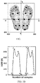
- FIG. 3A illustrates an exemplary representation of the plurality of pressure points of the foot corresponding to the plurality of pressure sensors arranged in the insole, in accordance with some embodiments of the present disclosure.
- the pressure points are selected with reference to an arbitrary reference coordinate system.
- an arbitrary axis is placed such that a left foot is positioned on positive axis and a right foot is positioned on negative axis. Further, upper half section of the left foot and the right foot are positioned on positive axis and lower half of the left foot and the right foot are positioned on negative axis.
- placement of said arbitrary axis is utilized for calculating a center of pressure when the subject is walking.
- the VGRF data recorded under each foot are normalized in association with body weight of the subject.
- the gait dynamics analysis unit 250 of the system 200 can be configured to calculate the stride information from the VGRF data associated with the each of the plurality of pressure sensors.
- FIG. 3B is an exemplary graph showing the VGRF data and a corresponding stride information, according to some embodiments of the present disclosure. Referring to FIG. 3B , a nature of VGRF of the subject while walking is shown. Here, each cycle includes two peaks, corresponding to the phases of the gait cycle and a single gait cycle is known as stride. A plurality of gait parameters including stride time, velocity, can be calculated from the gait cycle.. In an embodiment, the stride information is calculated from the VGRF data by utilizing a peak detection algorithm.
- each of the plurality of pressure sensor corresponds to the plurality of pressure points in the foot of the subject, and each pressure point corresponds to the node in the connectivity graph.
- Each line connecting two adjacent nodes forms an edge of the graph.
- ) is the number of nodes and M ( M
- V vertices
- ) is the number of edges.
- the vertex can be alternatively called as node.
- the graph can be alternatively called as the connectivity graph.
- the graph is generated using 100 consecutive stride information for left foot of each of the subject. Further, Performance of the connectivity graph depends on a sparsity value associated with the connectivity graph. In an embodiment, the sparsity value is selected as the largest possible threshold so that all nodes in the connectivity graph are connected at least to another node in the connectivity graph. In another embodiment, a plurality of connectivity graphs are generated for each subject by varying the sparsity value between 0 to 1 in steps of 0.1.
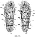
- FIG. 4A is an exemplary diagram illustrating the connectivity graph of the control subject, accordance with some embodiments of the present disclosure.
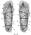
- FIG. 4B is an exemplary diagram illustrating the connectivity graph of the Parkinson's disease subject, accordance with some embodiments of the present disclosure.
- density of edges is more in Parkinson's disease subject than the control subject.
- 4B are thicker than the plurality of edges 420, 404, 406, 408, 410, 412, 414, 416, 418, 420, 422, 424, 426, 430, 432, 434, 436, 438, 440, 442, 444, 446, 448, 450, and 452 as shown in FIG. 4A .
- the thickness associated with the edges of the connectivity graph of the Parkinson's disease subject illustrates that the Parkinson's disease subject gives more pressure on the edges of the foot.
- the gait dynamics analysis unit 250 of the system 200 can be configured to calculate the mediolateral stability index from the calculated stride information associated with each node in the connectivity graph based on the betweenness centrality associated with each node.
- the method of calculating the mediolateral stability index from the stride information associated with each node of the connectivity graph based on the betweenness centrality associated with each node includes (i) calculating, a Pearson's correlation coefficient associated with each edge from the plurality of edges based on the stride information associated with two adjacent nodes connected by each edge (ii) Constructing, a weighted adjacency matrix from the connectivity graph based on the Pearson's correlation coefficient associated with each edge from the plurality of edges (iii) Calculating, a total number of shortest paths from a source node to a sink node by utilizing the weighted adjacency matrix (iv) Calculating, for each node, a number of shortest paths from the source node to the sink node passing through each node by utilizing the weight
- the source node can be node 1 and the sink node can be node 8.
- the source node can be node 8 and the sink node can be node 1 (v) Calculating, a betweenness centrality for each node excluding the source node and the sink node by dividing the number of shortest paths from the source node to the sink node passing through each node by the total number of shortest paths from the source node to the sink node and (vi) Calculating, a mediolateral stability index from the betweenness centrality associated with each node based on a difference between the betweenness centrality associated with each node and a set of adjacent nodes associated with each node.
- the betweenness centrality is utilized to measure an influence associated with a given node over the flow of information between all other nodes in the connectivity graph.
- the betweenness centrality associated with each node is calculated by utilizing the equation 1.
- B i ⁇ m ⁇ i ⁇ n ⁇ G ⁇ mn i ⁇ mn
- ⁇ mn ( i ) is the number of shortest paths from node 'm' to node 'n' that passes through node 'i'
- ⁇ mn is the total number of shortest paths from node 'm' to node 'n'.
- the betweenness centrality includes information of one pressure point in association with all other pressure points.
- a plurality of node pairs are selected for calculating the mediolateral stability index.
- the plurality of node pairs includes node pair (2,3), node pair (4,5) and node pair (6,7) as shown in FIG. 5 .
- the mediolateral stability index associated with the node pair (2,3) is calculated using the equation 2.
- the betweenness centrality of the node 3 is subtracted from the betweenness centrality of the node 2 to obtain the mediolateral stability index of the node pair (2,3).
- the mediolateral stability index associated with the node pair (4,5) is calculated using the equation 3.
- the betweenness centrality of the node 5 is subtracted from the betweenness centrality of the node 4 to obtain the mediolateral stability index of the node pair (4,5).
- the mediolateral stability index associated with the node pair (6,7) is calculated using the equation 4.
- the betweenness centrality of the node 7 is subtracted from the betweenness centrality of the node 6 to obtain the mediolateral stability index of the node pair (6,7).
- the gait dynamics analysis unit 250 of the system 200 can be configured to detect an intensity of the Parkinson's disease of the subject by comparing the mediolateral stability index with a predetermined value.
- the intensity of the Parkinson's disease of the subject is classified into one of no Parkinson's disease, mild Parkinson's disease, moderate Parkinson's disease and severe Parkinson's disease.
- the predetermined value is calculated based on a plurality of graph metrics. The method of calculating the plurality of graph metrics is described below.
- the plurality of graph metrics includes Clustering Coefficient (CC), Modularity (M), Characteristic Path Length (CPL), Local Efficiency (LE) and Link Density (LD) for the control group (CO) and Parkinson's disease (PD) group by utilizing the sparsity value of 0.3.
- CC Clustering Coefficient
- M Modularity
- CPL Characteristic Path Length
- LE Local Efficiency
- LD Link Density
- calculating the modularity of the graph provides a group of structurally or functionally associated nodes.
- modularity is a statistic to quantify a degree to which the network can be subdivided into clearly delineated groups.
- the modularity is measured by the equation 5.
- Q 1 2 m ⁇ ij A ij ⁇ K i K j 2 m ⁇ C i C j
- a ij is a weight associated with an edge between a node 'i' and a node 'j'.
- K i is a sum of weights of the edges attached to the node 'i'
- K j is a sum of weights of the edges attached to the node 'j'.
- 'm' is the sum of all of the edge weights of the graph.
- C i , C j are the group of the nodes and ⁇ is a simple delta function.
- Link density (LD) of the graph is measured by the equation 6. num nodes num nodes ⁇ 1 / 2 where num nodes is the maximum number of nodes in the graph. If the LD value is high, the density of the graph is more. The variation in LD is more for the control subjects and the Parkinson's disease subjects, for example p ⁇ 0.05. Further, the mean LD is higher in Parkinson's disease subject and the foot of the Parkinson's disease subject appears to be flat, and hence there exists strong links between the pressure points as shown in FIG. 4A and 4B .
- G Global efficiency and local efficiency measures the ability of a network to transmit information at the global and local level.
- the global efficiency is given by the equation 7.
- E glob G 1 N N ⁇ 1 ⁇ i ⁇ Gj ⁇ G , i ⁇ j 1 d ij
- d ij is the shortest path length between the node 'i' and the node 'j' in G.
- the global efficiency of G is given by the equation 8.
- E glob G 1 N ⁇ i ⁇ G E glob G i
- E glob ( G ) is the global efficiency of G i , wherein G i is a subgraph obtained from a plurality of neighbors associated with the node 'i'.
- the clustering coefficient C i of a node 'i' is given by the equation 9.
- C i 2 T d i d i ⁇ 1
- T indicates a number existing connections among the neighbors of 'i' and d i is a degree associated with the node 'i'.
- Table 1 below provides a comparison of the plurality of graph metrics between left legs in CO subject and Parkinson's disease (PD) subject.
- Table 1 Average CO (left foot) Average PD (left foot) p -value M 0.375483 0.304818 0.005468 LD 0.366093 0.417035 0.001904 Cpl 328.9 462.01 0.000408 CC 0.6 0.69 0.003 LE 0.340 0.830 0.002
- the calculated plurality of graph metrics for Parkinson's disease (PD) and Control group (CO) is given.
- the plurality of graph metrics, except 'Modularity' provides statistically significant result at the selected sparsity value of 0.3.
- PD group that is the 'Mild' and 'Moderate' or 'Control' and 'Mild' group
- no statistically significant results were obtained.
- physical significance of conventional graph metric values are difficult to interpret in this scenario.
- Conventional graph theoretic features can differentiate between control and PD group, but cannot differentiate between stages of PD or neither can evaluate early detection or quantify disease progression.
- the mediolateral stability index based categorization of the subjects is as shown in Table 2A.
- Table 2B and Table 2C As depicted in Tables 2A, 2B and 2C, the calculated mediolateral stability index is utilized for a plurality of categorization including the control subject and the Parkinson Disease (PD) subject, the control subject and the Mild PD subject and the Mild PD subject and the moderate PD subject.
- PD Parkinson Disease
- the control subject and the Mild PD subject and the Mild PD subject and the moderate PD subject For differentiating between the control subject and PD subject, all the node pair shows statistically significant result.
- the node pairs (4, 5) and (6, 7) provides statistically significant result.
- Table 2A Node Pair MLSI for Control subject MLSI for PD subject P value (accuracy) ( ⁇ 0.05) 2-3 1.21 5.7 0.0431* 4-5 3.35 9.1 0.021* 6-7 0.41 2.9 0.013*
- Table 2B Node Pair MLSI for Control subject MLSI for Mild PD subject P value 2-3 4.03 1.6 0.021* 4-5 8.4 5.1 0.045* 6-7 0.21 0.22 0.073
- Table 2C Node Pair MLSI for Mild PD subject MLSI for Moderate PD subject P value 2-3 1.63 4.1 0.023* 4-5 4.8 7.2 0.113* 6-7 0.2 1.1 0.052
- the table 2 indicated that, the MLS metric effectively distinguishes Control, Mild and Moderate group and also indicates that as PD progresses, abrupt and chaotic behavior are most likely to occur in the upper quadrant of foot, precisely the area between (4, 5) and (6, 7) node pairs (pressure zone).
- the '*' in the table indicates that the p value is less than 0.05 and when the p value is less than 0.05, the differentiation between the control subject and PD subject, the control subject and the mild PD subject, the control subject and the moderate PD subject is clear.
- the category of the subject obtained by the present disclosure is compared with a Hoehn and Yahr (HY) scale to test the efficiency of the present disclosure.
- the present disclosure is providing results equivalent to the HY scale.
- the present disclosure provides more categories including 'mild Parkinson's disease' and 'moderate Parkinson's disease' which are not available in the HY scale.
- the HY scale is a standard manual calculation method used for detecting the Parkinson's disease.
- a progression of the Parkinson's disease is identified in the range of 0 to 5 in HY scale, wherein 0 in the HY scale indicates that there is 'no' Parkinson's disease, 2 in the HY scale indicates 'mild' Parkinson's disease, the value between 2 and 5 in the Hy scale indicates 'moderate' Parkinson's disease and 5 in the HY scale indicates that the Parkinson's disease is 'severe'.
- FIG. 6A , 6B and 6C are exemplary graphs illustrating variation of the mediolateral stability index (MLSI) corresponding to a plurality of sparsity values for three pair of pressure points across the control subject, a mild Parkinson's disease subject and a moderate Parkinson's disease subject, in accordance with some embodiments of the present disclosure.
- a variation of the mediolateral stability index corresponding to the plurality of sparsity values of the Control subject is plotted as A.
- the variation of the mediolateral stability index corresponding to the plurality of sparsity values of the mild Parkinson's disease subject is plotted as B.
- the variation of the mediolateral stability index corresponding to the plurality of sparsity values of the moderate Parkinson's disease subject is plotted as C.
- the sparsity value is varied from 0 to 1.
- the variation of the mediolateral stability index corresponding to the plurality of sparsity value for the node pair (2,3) is plotted for the control subject, the mild Parkinson's disease subject and the moderate Parkinson's disease subject.
- the variation of the mediolateral stability index corresponding to the plurality of sparsity value for the node pair (4,5) is plotted for the control subject, the mild Parkinson's disease subject and the moderate Parkinson's disease subject.
- the variation of the mediolateral stability index corresponding to the plurality of sparsity value for the node pair (6,7) is plotted for the control subject, the mild Parkinson's disease subject and the moderate Parkinson's disease subject.
- the sparsity value of 0.3 provides statistically significant result.
- FIG. 7 illustrates a flow diagram for the method 700 for detecting Parkinson's disease, according to some embodiments of the present disclosure.
- the method 700 may be described in the general context of computer executable instructions.
- computer executable instructions can include routines, programs, objects, components, data structures, procedures, modules, functions, etc., that perform particular functions or implement particular abstract data types.
- the method 700 may also be practiced in a distributed computing environment where functions are performed by remote processing devices that are linked through a communication network.
- the order in which the method 700 is described is not intended to be construed as a limitation, and any number of the described method blocks can be combined in any order to implement the method 700, or an alternative method.
- the method 700 can be implemented in any suitable hardware, software, firmware, or combination thereof.
- FIG. 7 is a flow diagram illustrating a method 700 for detecting Parkinson's disease progression of the subject, in accordance with some embodiments of the present disclosure.
- the system 200 receives, by a one or more hardware processors, the Vertical Ground Reaction Force (VGRF) data from each of the plurality of pressure sensors attached to the insole.
- the system 200 determines, by the one or more hardware processors, the stride information for each of the plurality of pressure sensors from the corresponding VGRF data, wherein each of the plurality of pressure sensors correspond to a plurality of pressure points in the foot of the subject, and each pressure point corresponds to a node in the connectivity graph.
- VGRF Vertical Ground Reaction Force
- the system 200 calculates by the one or more hardware processors, the mediolateral stability index from the calculated stride information associated with each node in the connectivity graph based on the betweenness centrality associated with each node.
- the system 200 detects by the one or more hardware processors, the intensity of the Parkinson's disease of the subject by comparing the mediolateral stability index with a predetermined value.
- FIG. 8 is a flow diagram illustrating a method of calculating the mediolateral stability index from the calculated stride information associated with each node in the graph based on the betweenness centrality associated with each node, in accordance with some embodiments of the present disclosure.
- the Pearson's correlation coefficient associated with each edge from the plurality of edges is calculated.
- two adjacent nodes are connected by an edge and the Pearson correlation coefficient of edge is calculated based on the stride information associated with the adjacent nodes connected by the edge.
- the weighted adjacency matrix is constructed from the connectivity graph based on the Pearson's correlation coefficient associated with each edge from the plurality of edges.
- a total number of shortest paths from a source node to a sink node is calculated by utilizing the weighted adjacency matrix.
- a number of shortest paths from the source node to the sink node passing through each node is calculated by utilizing the weighted adjacency matrix.
- a betweenness centrality is calculated for each node excluding the source node and the sink node by dividing the number of shortest paths from the source node to the sink node passing through each node by the total number of shortest paths from the source node to the sink node.
- the mediolateral stability index is calculated from the betweenness centrality associated with each node based on a difference between the betweenness centrality associated with each node and a set of adjacent nodes of each node.
- the data set used for experimentation includes a set of Vertical Ground Reaction Force (VGRF) data of 93 subjects with idiopathic Parkinson's disease (mean age: 66.3 years) with moderate disease severity and 73 control subjects.
- the control subjects were free from any neurological or gait related disorders. All the subjects with Parkinson's disease had mild to moderate Parkinson's disease, as concluded from Hoehn-Yahr (HY) scale (value between 2 to 3).
- the subjects were asked to walk for a distance of 100 m in their self-selected speed, wearing an instrumented shoe, fitted with insole sensors at dedicated pressure points. There are 16 sensors in total, 8 for each foot. The sensors measured VGRF data under the foot at the point of placement.
- VGRF Data were acquired at 100 Hz sampling frequency.
- the VGRF data were filtered to reduce spurious noise and suppress raw signal readout below 20N and the VGRF data collected during the first 20 seconds of the plurality of pressure sensors were discarded. Further the VGRF data is weight normalized using the demographic information given in the database.
- human gait cycle includes a periodic stance and swing pattern and the human gait cycle is processed to extract stride information.
- a stride cycle is the period of time during which a foot touches the ground known as heel strike phase, goes off the ground (toe off phase), and again makes contact with the ground.
- Maximum VGRF is calculated as the mean of maximum value in each stride for total 35 strides of both legs of each subject, considering all 8 sensors for each foot. Average of maximum VGRF reported by the 8 pressure sensors is calculated for 35 consecutive strides.
- PD subjects shows higher relative load in the forefoot regions, resulting in flat-foot gait.
- Results obtained from the experimentation indicates a characteristic flat footedness for PD groups.
- calculated MLS index shows more prominence in the forefoot region.
- the Medial load shifting bias or a change in load distribution and its fluctuations in PD subjects as PD progresses reflects the differential dynamics of PD gait.
- the calculated MLS metric incorporates the hidden dynamism in the medial load distribution pattern and its changes as PD progresses.
- the present disclosure along with traditional gait variables like stride time, swing time variability, can be used to augment the accuracy of the disease severity estimation.
- the mediolateral stability index metric along with the insole can serve as an indicator for medication dose adjustment as per the activity and stability of the specific subject, monitored through the insole combined with smart phone application.
- a step by step procedure to calculate the mediolateral stability index is as provided in example code below:
- the embodiments of present disclosure herein addresses unresolved problem of identifying biomarkers for detecting progression of Parkinson's disease.
- the embodiment thus provides graph connectivity approach to derive a novel metric associated with changes in mediolateral pressure distribution based on the VGRF data obtained from the insole. Further, the mediolateral stability index is utilized as a screening index to measure flat footedness of the subject. Moreover, the embodiments herein further provides, a monitoring system for Parkinson's disease.
- the hardware device can be any kind of device which can be programmed including e.g. any kind of computer like a server or a personal computer, or the like, or any combination thereof.
- the device may also include means which could be e.g. hardware means like e.g. an application-specific integrated circuit (ASIC), a field-programmable gate array (FPGA), or a combination of hardware and software means, e.g.
- ASIC application-specific integrated circuit
- FPGA field-programmable gate array
- the means can include both hardware means and software means.
- the method embodiments described herein could be implemented in hardware and software.
- the device may also include software means.
- the embodiments may be implemented on different hardware devices, e.g. using a plurality of CPUs.
- the embodiments herein can comprise hardware and software elements.
- the embodiments that are implemented in software include but are not limited to, firmware, resident software, microcode, etc.
- the functions performed by various modules described herein may be implemented in other modules or combinations of other modules.
- a computer-usable or computer readable medium can be any apparatus that can comprise, store, communicate, propagate, or transport the program for use by or in connection with the instruction execution system, apparatus, or device.
- a computer-readable storage medium refers to any type of physical memory on which information or data readable by a processor may be stored.
- a computer-readable storage medium may store instructions for execution by one or more processors, including instructions for causing the processor(s) to perform steps or stages consistent with the embodiments described herein.
- the term "computer-readable medium” should be understood to include tangible items and exclude carrier waves and transient signals, i.e., be non-transitory. Examples include random access memory (RAM), read-only memory (ROM), volatile memory, nonvolatile memory, hard drives, CD ROMs, DVDs, flash drives, disks, and any other known physical storage media.
Landscapes
- Health & Medical Sciences (AREA)
- Life Sciences & Earth Sciences (AREA)
- Engineering & Computer Science (AREA)
- Public Health (AREA)
- Medical Informatics (AREA)
- Biomedical Technology (AREA)
- Pathology (AREA)
- General Health & Medical Sciences (AREA)
- Surgery (AREA)
- Biophysics (AREA)
- Physics & Mathematics (AREA)
- Heart & Thoracic Surgery (AREA)
- Molecular Biology (AREA)
- Animal Behavior & Ethology (AREA)
- Veterinary Medicine (AREA)
- Neurology (AREA)
- Physiology (AREA)
- Neurosurgery (AREA)
- Data Mining & Analysis (AREA)
- Dentistry (AREA)
- Oral & Maxillofacial Surgery (AREA)
- Databases & Information Systems (AREA)
- Epidemiology (AREA)
- Primary Health Care (AREA)
- Developmental Disabilities (AREA)
- Artificial Intelligence (AREA)
- Computer Vision & Pattern Recognition (AREA)
- Psychiatry (AREA)
- Signal Processing (AREA)
- Measurement Of The Respiration, Hearing Ability, Form, And Blood Characteristics Of Living Organisms (AREA)
Abstract
Description
- This patent application claims priority to India Patent Application
201921007036, filed on February 22, 2019 - The disclosure herein generally relates to health monitoring, and, more particularly, to a method and system for detecting Parkinson's disease progression.
- Parkinson's disease is a neuro-degenerative disorder causing motor and cognitive impairments in subjects. Major motor impairments includes gait impairments like freezing of gait, reshuffled gait, asymmetry in upper limb motion during gait, slowed movement, resting tremor, rigidity and postural instability. Since symptom manifestation is limited in Parkinson's disease, identifying Parkinson's disease in the early stage and monitoring the progression of the Parkinson's disease is a challenging task.
- Conventional methods focus either on symptom manifestations of a subject to detect the Parkinson's Disease (PD) or on common gait features of subjects like stride time and swing time to monitor the progression of the PD. Since the gait features are univariate functions, there is a challenge in monitoring the progression of the PD. Further, in early stage of the Parkinson's disease the symptom may not be strong and distinct. Hence, symptom based approaches provide lower accuracy in detection of the disease and hence not a preferred approach for early detection. Recently, existing approaches are analyzing standard gait metrics like stride length that arises due to interaction of the insole pressure points to detect the PD. However, these existing methods provide only gait abnormality analysis, profound only in the advanced stage of the PD. Hence there is a challenge in detecting PD of the subject in early stages.
- Embodiments of the present disclosure present technological improvements as solutions to one or more of the above-mentioned technical problems recognized by the inventors in conventional systems. For example, in one embodiment, a method for detecting Parkinson's disease progression is provided. The method includes receiving, a Vertical Ground Reaction Force (VGRF) data from each of a plurality of pressure sensors attached to an insole. Further, the method includes determining, a stride information for each of the plurality of pressure sensors from the corresponding VGRF data, wherein each of the plurality of pressure sensors correspond to a plurality of pressure points in a foot of the subject, and each pressure point corresponds to a node in a graph. Furthermore, the method includes calculating, a mediolateral stability index from the calculated stride information associated with each node in the graph based on a betweenness centrality associated with each node. Finally, the method includes detecting an intensity of the Parkinson's disease of the subject by comparing the mediolateral stability index with a predetermined value.
- In another aspect, a system for detecting Parkinson's disease progression is provided. The system includes an insole with a plurality of pressure sensors, at least one memory comprising programmed instructions, at least one hardware processor operatively coupled to the at least one memory, wherein the at least one hardware processor are capable of executing the programmed instructions stored in the at least one memories; and a gait dynamics analysis unit, wherein the gait dynamics analysis unit is configured to receive, a Vertical Ground Reaction Force (VGRF) data from each of a plurality of pressure sensors attached to an insole. Further, the gait dynamics analysis unit is configured to determine, a stride information for each of the plurality of pressure sensors from the corresponding VGRF data, wherein each of the plurality of pressure sensors correspond to a plurality of pressure points in a foot of the subject, and each pressure point corresponds to a node in a graph. Furthermore, the gait dynamics analysis unit is configured to calculate, a mediolateral stability index from the calculated stride information associated with each node in the graph based on a betweenness centrality associated with each node. Finally, the gait dynamics analysis unit is configured to detect, an intensity of the Parkinson's disease of the subject by comparing the mediolateral stability index with a predetermined value.
- In yet another aspect, a computer program product comprising a non-transitory computer-readable medium having embodied therein a computer program for method and system for detecting Parkinson's disease progression, is provided. The computer readable program, when executed on a computing device, causes the computing device to receive, a Vertical Ground Reaction Force (VGRF) data from each of a plurality of pressure sensors attached to an insole. Further, the computer readable program, when executed on a computing device, causes the computing device to determine, a stride information for each of the plurality of pressure sensors from the corresponding VGRF data, wherein each of the plurality of pressure sensors correspond to a plurality of pressure points in a foot of the subject, and each pressure point corresponds to a node in a graph. Furthermore, the computer readable program, when executed on a computing device, causes the computing device to calculate, a mediolateral stability index from the calculated stride information associated with each node in the graph based on a betweenness centrality associated with each node. Finally, the computer readable program, when executed on a computing device, causes the computing device to detect, an intensity of the Parkinson's disease of the subject by comparing the mediolateral stability index with a predetermined value.
- It is to be understood that both the foregoing general description and the following detailed description are exemplary and explanatory only and are not restrictive of the invention, as claimed.
- The accompanying drawings, which are incorporated in and constitute a part of this disclosure, illustrate exemplary embodiments and, together with the description, serve to explain the disclosed principles:
-
FIG. 1 illustrates an exemplary networking environment for implementing a system for detecting Parkinson's disease progression according to some embodiments of the present disclosure. -
FIG. 2 is a functional block diagram of the system for detecting Parkinson's disease progression according to some embodiments of the present disclosure. -
FIG. 3A illustrates an exemplary representation of a plurality of pressure points of a foot corresponding to a plurality of pressure sensors arranged in an insole, in accordance with some embodiments of the present disclosure. -
FIG. 3B is an exemplary graph showing Vertical Ground Reaction Force (VGRF) data and corresponding stride information, according to some embodiments of the present disclosure. -
FIG. 4A is an exemplary diagram illustrating a connectivity graph of a control subject, accordance with some embodiments of the present disclosure. -
FIG. 4B is an exemplary diagram illustrating a connectivity graph of a Parkinson's disease subject, accordance with some embodiments of the present disclosure. -
FIG. 5 is an exemplary diagram illustrating three pairs of adjacent pressure points from the connectivity graph utilized for calculating a mediolateral stability index, accordance with some embodiments of the present disclosure. -
FIG. 6A ,6B and6C are exemplary graphs illustrating variation of the mediolateral stability index corresponding to a plurality of sparsity values for three pair of pressure points across the control subject, a mild Parkinson's disease subject and a moderate Parkinson's disease subject, in accordance with some embodiments of the present disclosure. -
FIG. 7 is a flow diagram illustrating a method for detecting a Parkinson's disease progression of the subject, in accordance with some embodiments of the present disclosure and -
FIG. 8 is a flow diagram illustrating a method of calculating the mediolateral stability index from the calculated stride information associated with each node in the graph based on the betweenness centrality associated with each node, in accordance with some embodiments of the present disclosure. - Exemplary embodiments are described with reference to the accompanying drawings. In the figures, the left-most digit(s) of a reference number identifies the figure in which the reference number first appears. Wherever convenient, the same reference numbers are used throughout the drawings to refer to the same or like parts. While examples and features of disclosed principles are described herein, modifications, adaptations, and other implementations are possible without departing from the spirit and scope of the disclosed embodiments.
- Provided below are definitions of a plurality if terms used herein.
- Control subject (CO): A subject not having Parkinson's disease.
- Stride information: A stride information refers to a period of time comprising a heel strike phase followed by a toe off phase further back to the heel strike phase. The heel strike phase refers to a gesture of a subject when a foot of the subject makes contact with ground. The toe off phase refers to the gesture when a toe of the subject goes off the ground.
- Modularity (M): Modularity is a measure of nodes forming modules and the modules refers to a set of nodes with denser links among them and sparser links with rest of the graph.
- Characteristic Path Length (CPL): CPL is an average path length in a connectivity graph, where a path length is defined as the minimum number of edges to be traversed from one node of the connectivity graph to another node.
- Clustering Coefficient (CC): Clustering coefficient provides an indication of connectivity of a node with a plurality of neighboring nodes in the connectivity graph.
- Embodiments herein provide a method and system for detecting Parkinson's disease progression. The present subject matter overcomes the limitations of the conventional methods for detecting Parkinson's disease progression by utilizing a graph theory approach. Here, the graph theory based approach is utilized to analyze foot dynamics of the subject. A plurality of pressure sensors are attached to an insole corresponding to a plurality of pressure points associated with the foot of the subject. Each pressure point associated with the foot of the subject is considered as a node of a connectivity graph. The foot dynamics analysis is performed based on a metric known as mediolateral stability index and the mediolateral stability index is calculated by utilizing a betweenness centrality associated with each node of the connectivity graph. Further, the mediolateral stability index is compared with standard values to detect the intensity of the Parkinson's disease. An implementation of the method and system for detecting Parkinson's disease progression is described further in detail with reference to
FIGS. 1 through 8 . - Referring now to the drawings, and more particularly to
FIG. 1 through 8 , where similar reference characters denote corresponding features consistently throughout the figures, there are shown preferred embodiments and these embodiments are described in the context of the following exemplary system and/or method. -
FIG. 1 illustrates an exemplary networking environment for implementing a system for detecting Parkinson's disease progression, according to an example embodiment of the present subject matter. Thesystem 100 for detecting Parkinson's disease progression, hereinafter referred to as thesystem 100, includes acomputing device 104, aninsole unit 106 and anetwork 108. Here thecomputing device 104 can be one among a variety of computing systems, such as a laptop computer, a desktop computer, a notebook, a workstation, a cloud-based computing device, a router, a network gateway, a sensor gateway, a wifi access point and the like. In one implementation, thesystem 100 may be implemented in a cloud-based environment. In another implementation, thesystem 100 can be implemented in a cloud-edge environment and in yet another implementation, thesystem 100 can be implemented in a cloud-fog environment. Theinsole unit 108 and thecomputing device 104 are communicatively coupled through anetwork 108. - In an embodiment, the
network 108 may be a wireless or a wired network, or a combination thereof. In an example, thenetwork 108 can be implemented as a computer network, as one of the different types of networks, such as virtual private network (VPN), intranet, local area network (LAN), wide area network (WAN), the internet, and such. Thenetwork 108 may either be a dedicated network or a shared network, which represents an association of the different types of networks that use a variety of protocols, for example, Hypertext Transfer Protocol (HTTP), Transmission Control Protocol/Internet Protocol (TCP/IP), and Wireless Application Protocol (WAP), to communicate with each other. Further, thenetwork 108 may include a variety of network devices, including routers, bridges, servers, computing devices, storage devices. The network devices within thenetwork 108 may interact with the each other through communication links. - In an embodiment, the
insole unit 106 includes aninsole 124, asignal transmission unit 126, apower supply 122 and acontrol circuit 120. Theinsole 124 includes a plurality of pressure sensors and each pressure sensor from the plurality of pressure sensors attached with theinsole 124 corresponds to a plurality of pressure points associated with the foot of the subject. Each of the plurality of pressure sensors measures a Vertical Ground Reaction Force (VGRF) data associated with the particular pressure point of the foot. In an embodiment, eight pressure points are identified and hence eight pressure sensors are attached in the insole corresponding to the eight pressure points. In an embodiment, the plurality of pressure sensors may include Ultraflex Computer Dyno Graphy™, Infotronic Inc. ™. Thesignal transmission unit 126 collects a plurality of VGRF data from the plurality of pressure sensors and transmits the plurality of VGRF data to thecomputing device 104. Thepower supply 122 supplies power to the plurality of pressure sensors attached to theinsole 124, thesignal transmission unit 126 and thecontrol circuit 120. Thecontrol circuit 120 controls and coordinates a plurality of functions associated with theinsole unit 106. -
FIG. 2 illustrates a block diagram of acomputing device 104, according to some embodiments of the present disclosure. The computing device 104 (hereinafter referred to as system 200) includes or is otherwise in communication with one or more hardware processors such as aprocessor 202, at least one memory such as amemory 204, an I/O interface 206 and a gaitdynamics analysis unit 250. In an embodiment, the gaitdynamics analysis unit 250 comprising a stride information calculation module (not shown inFIG. 2 ), a mediolateral stability index calculation module (not shown inFIG. 2 ), and a categorization module (not shown inFIG. 2 ). Theprocessor 202,memory 204, and the I/O interface 206 may be coupled by a system bus such as asystem bus 208 or a similar mechanism. - The I/
O interface 206 may include a variety of software and hardware interfaces, for example, a web interface, a graphical user interface, and the like. Theinterfaces 206 may include a variety of software and hardware interfaces, for example, interfaces for peripheral device(s), such as a keyboard, a mouse, an external memory, a camera device, and a printer. Further, theinterfaces 206 may enable thesystem 200 to communicate with other devices, such as web servers and external databases. Theinterfaces 206 can facilitate multiple communications within a wide variety of networks and protocol types, including wired networks, for example, local area network (LAN), cable, etc., and wireless networks, such as Wireless LAN (WLAN), cellular, or satellite. For the purpose, theinterfaces 206 may include one or more ports for connecting a number of computing systems with one another or to another server computer. The I/O interface 206 may include one or more ports for connecting a number of devices to one another or to another server. - The
hardware processor 202 may be implemented as one or more microprocessors, microcomputers, microcontrollers, digital signal processors, central processing units, state machines, logic circuitries, and/or any devices that manipulate signals based on operational instructions. Among other capabilities, thehardware processor 202 is configured to fetch and execute computer-readable instructions stored in thememory 204. - The
memory 204 may include any computer-readable medium known in the art including, for example, volatile memory, such as static random access memory (SRAM) and dynamic random access memory (DRAM), and/or non-volatile memory, such as read only memory (ROM), erasable programmable ROM, flash memories, hard disks, optical disks, and magnetic tapes. In an embodiment, thememory 204 includes a plurality ofmodules 220 and arepository 240 for storing data processed, received, and generated by one or more of themodules 220 and the gaitdynamics analysis unit 250. Themodules 220 may include routines, programs, objects, components, data structures, and so on, which perform particular tasks or implement particular abstract data types. - The
memory 204 also includes module(s) 220 and adata repository 240. The module(s) 220 include programs or coded instructions that supplement applications or functions performed by thesystem 100 for detecting Parkinson's disease progression. Themodules 220, amongst other things, can include routines, programs, objects, components, and data structures, which perform particular tasks or implement particular abstract data types. Themodules 220 may also be used as, signal processor(s), state machine(s), logic circuitries, and/or any other device or component that manipulates signals based on operational instructions. Further, themodules 220 can be used by hardware, by computer-readable instructions executed by a processing unit, or by a combination thereof. Themodules 220 can include various sub-modules (not shown). Themodules 220 may include computer-readable instructions that supplement applications or functions performed by the system a00 for detecting Parkinson's disease progression. - The
data repository 240 may include received set of tasks, areference database 244, aVGRF database 246 andother data 248. Further, theother data 248 amongst other things, may serve as a repository for storing data that is processed, received, or generated as a result of the execution of one or more modules in the module(s) 220 and the modules associated with the gaitdynamics analysis unit 250. - Although the
data repository 240 is shown internal to thesystem 200, it will be noted that, in alternate embodiments, thedata repository 240 can also be implemented external to thesystem 200, where thedata repository 240 may be stored within a database (not shown inFIG. 2 ) communicatively coupled to thesystem 200. The data contained within such external database may be periodically updated. For example, new data may be added into the database (not shown inFIG. 2 ) and/or existing data may be modified and/or non-useful data may be deleted from the database (not shown inFIG. 2 ). In one example, the data may be stored in an external system, such as a Lightweight Directory Access Protocol (LDAP) directory and a Relational Database Management System (RDBMS). In another embodiment, the data stored in thedata repository 240 may be distributed between the 200 and the external database. - The gait
dynamics analysis unit 250 of thesystem 200 can be configured to receive a Vertical Ground Reaction Force (VGRF) data from each of the plurality of pressure sensors attached with theinsole 124. Each of the plurality of pressure sensors measures the VGRF data associated with the particular pressure point of the foot at 100 Hz sampling frequency. Further, the VGRF data is filtered to reduce spurious noise and to suppress raw signal less than 20 N. Further, the VGRF data during the initial 20 seconds of each pressure sensor is discarded. In an embodiment, eight pressure points are identified and eight pressure sensors are attached in the insole corresponding to the eight pressure points.FIG. 3A illustrates an exemplary representation of the plurality of pressure points of the foot corresponding to the plurality of pressure sensors arranged in the insole, in accordance with some embodiments of the present disclosure. Referring toFIG. 3A , the pressure points are selected with reference to an arbitrary reference coordinate system. Here, an arbitrary axis is placed such that a left foot is positioned on positive axis and a right foot is positioned on negative axis. Further, upper half section of the left foot and the right foot are positioned on positive axis and lower half of the left foot and the right foot are positioned on negative axis. In an embodiment, placement of said arbitrary axis is utilized for calculating a center of pressure when the subject is walking. The VGRF data recorded under each foot are normalized in association with body weight of the subject. - Further, the gait
dynamics analysis unit 250 of thesystem 200 can be configured to calculate the stride information from the VGRF data associated with the each of the plurality of pressure sensors.FIG. 3B is an exemplary graph showing the VGRF data and a corresponding stride information, according to some embodiments of the present disclosure. Referring toFIG. 3B , a nature of VGRF of the subject while walking is shown. Here, each cycle includes two peaks, corresponding to the phases of the gait cycle and a single gait cycle is known as stride. A plurality of gait parameters including stride time, velocity, can be calculated from the gait cycle.. In an embodiment, the stride information is calculated from the VGRF data by utilizing a peak detection algorithm. - In an embodiment, each of the plurality of pressure sensor corresponds to the plurality of pressure points in the foot of the subject, and each pressure point corresponds to the node in the connectivity graph. Each line connecting two adjacent nodes forms an edge of the graph. Here the graph G is defined as G(V, E) where, V is a set of vertices (nodes) and E is a set of edges, N (N = |V|) is the number of nodes and M (M = |E|) is the number of edges. For brevity of description the vertex can be alternatively called as node. For brevity of description, the graph can be alternatively called as the connectivity graph.
- In an embodiment, the graph is generated using 100 consecutive stride information for left foot of each of the subject. Further, Performance of the connectivity graph depends on a sparsity value associated with the connectivity graph. In an embodiment, the sparsity value is selected as the largest possible threshold so that all nodes in the connectivity graph are connected at least to another node in the connectivity graph. In another embodiment, a plurality of connectivity graphs are generated for each subject by varying the sparsity value between 0 to 1 in steps of 0.1.
-
FIG. 4A is an exemplary diagram illustrating the connectivity graph of the control subject, accordance with some embodiments of the present disclosure.FIG. 4B is an exemplary diagram illustrating the connectivity graph of the Parkinson's disease subject, accordance with some embodiments of the present disclosure. Referring toFIG. 4A andFIG. 4B , density of edges is more in Parkinson's disease subject than the control subject. A plurality ofedges FIG. 4B are thicker than the plurality ofedges FIG. 4A . The thickness associated with the edges of the connectivity graph of the Parkinson's disease subject illustrates that the Parkinson's disease subject gives more pressure on the edges of the foot. - Further, the gait
dynamics analysis unit 250 of thesystem 200 can be configured to calculate the mediolateral stability index from the calculated stride information associated with each node in the connectivity graph based on the betweenness centrality associated with each node. The method of calculating the mediolateral stability index from the stride information associated with each node of the connectivity graph based on the betweenness centrality associated with each node includes (i) calculating, a Pearson's correlation coefficient associated with each edge from the plurality of edges based on the stride information associated with two adjacent nodes connected by each edge (ii) Constructing, a weighted adjacency matrix from the connectivity graph based on the Pearson's correlation coefficient associated with each edge from the plurality of edges (iii) Calculating, a total number of shortest paths from a source node to a sink node by utilizing the weighted adjacency matrix (iv) Calculating, for each node, a number of shortest paths from the source node to the sink node passing through each node by utilizing the weighted adjacency matrix. In an embodiment, referring toFIG. 5 , the source node can benode 1 and the sink node can benode 8. In another embodiment, the source node can benode 8 and the sink node can be node 1 (v) Calculating, a betweenness centrality for each node excluding the source node and the sink node by dividing the number of shortest paths from the source node to the sink node passing through each node by the total number of shortest paths from the source node to the sink node and (vi) Calculating, a mediolateral stability index from the betweenness centrality associated with each node based on a difference between the betweenness centrality associated with each node and a set of adjacent nodes associated with each node. - In an embodiment, the betweenness centrality is utilized to measure an influence associated with a given node over the flow of information between all other nodes in the connectivity graph. The betweenness centrality associated with each node is calculated by utilizing the
equation 1.
- In an embodiment, a plurality of node pairs are selected for calculating the mediolateral stability index. Here, the plurality of node pairs includes node pair (2,3), node pair (4,5) and node pair (6,7) as shown in
FIG. 5 . The mediolateral stability index associated with the node pair (2,3) is calculated using theequation 2. Here, the betweenness centrality of thenode 3 is subtracted from the betweenness centrality of thenode 2 to obtain the mediolateral stability index of the node pair (2,3). Similarly, the mediolateral stability index associated with the node pair (4,5) is calculated using theequation 3. Here, the betweenness centrality of thenode 5 is subtracted from the betweenness centrality of thenode 4 to obtain the mediolateral stability index of the node pair (4,5). The mediolateral stability index associated with the node pair (6,7) is calculated using theequation 4. Here, the betweenness centrality of thenode 7 is subtracted from the betweenness centrality of the node 6 to obtain the mediolateral stability index of the node pair (6,7).


- Further, the gait
dynamics analysis unit 250 of thesystem 200 can be configured to detect an intensity of the Parkinson's disease of the subject by comparing the mediolateral stability index with a predetermined value. Here, the intensity of the Parkinson's disease of the subject is classified into one of no Parkinson's disease, mild Parkinson's disease, moderate Parkinson's disease and severe Parkinson's disease. The predetermined value is calculated based on a plurality of graph metrics. The method of calculating the plurality of graph metrics is described below. - In an embodiment, the plurality of graph metrics includes Clustering Coefficient (CC), Modularity (M), Characteristic Path Length (CPL), Local Efficiency (LE) and Link Density (LD) for the control group (CO) and Parkinson's disease (PD) group by utilizing the sparsity value of 0.3.
- In an embodiment, calculating the modularity of the graph provides a group of structurally or functionally associated nodes. Alternatively, modularity is a statistic to quantify a degree to which the network can be subdivided into clearly delineated groups. The modularity is measured by the
equation 5.
- Link density (LD) of the graph is measured by the equation 6.

FIG. 4A and4B . - Efficiency: Global efficiency and local efficiency measures the ability of a network to transmit information at the global and local level. For the graph G(V, E), the global efficiency is given by the
equation 7.
equation 8.
- The clustering coefficient Ci of a node 'i' is given by the equation 9.

- Table 1 below provides a comparison of the plurality of graph metrics between left legs in CO subject and Parkinson's disease (PD) subject.
Table 1 Average CO (left foot) Average PD (left foot) p-value M 0.375483 0.304818 0.005468 LD 0.366093 0.417035 0.001904 Cpl 328.9 462.01 0.000408 CC 0.6 0.69 0.003 LE 0.340 0.830 0.002 - As depicted in the table 1, the calculated plurality of graph metrics for Parkinson's disease (PD) and Control group (CO) is given. The plurality of graph metrics, except 'Modularity' provides statistically significant result at the selected sparsity value of 0.3. However, in between PD group, that is the 'Mild' and 'Moderate' or 'Control' and 'Mild' group, no statistically significant results were obtained. Also, physical significance of conventional graph metric values are difficult to interpret in this scenario. Conventional graph theoretic features can differentiate between control and PD group, but cannot differentiate between stages of PD or neither can evaluate early detection or quantify disease progression.
- In an embodiment, the mediolateral stability index based categorization of the subjects is as shown in Table 2A. Table 2B and Table 2C. As depicted in Tables 2A, 2B and 2C, the calculated mediolateral stability index is utilized for a plurality of categorization including the control subject and the Parkinson Disease (PD) subject, the control subject and the Mild PD subject and the Mild PD subject and the moderate PD subject. For differentiating between the control subject and PD subject, all the node pair shows statistically significant result. For early screening, the Control subject and the Mild PD subject, the node pairs (4, 5) and (6, 7) provides statistically significant result. For early screening, the Mild PD subject and Moderate PD subject, the node pairs (4, 5) and (6, 7) provides statistically significant result.
Table 2A Node Pair MLSI for Control subject MLSI for PD subject P value (accuracy) (<0.05) 2-3 1.21 5.7 0.0431* 4-5 3.35 9.1 0.021* 6-7 0.41 2.9 0.013* Table 2B Node Pair MLSI for Control subject MLSI for Mild PD subject P value 2-3 4.03 1.6 0.021* 4-5 8.4 5.1 0.045* 6-7 0.21 0.22 0.073 Table 2C Node Pair MLSI for Mild PD subject MLSI for Moderate PD subject P value 2-3 1.63 4.1 0.023* 4-5 4.8 7.2 0.113* 6-7 0.2 1.1 0.052 - The table 2 indicated that, the MLS metric effectively distinguishes Control, Mild and Moderate group and also indicates that as PD progresses, abrupt and chaotic behavior are most likely to occur in the upper quadrant of foot, precisely the area between (4, 5) and (6, 7) node pairs (pressure zone). The '*' in the table indicates that the p value is less than 0.05 and when the p value is less than 0.05, the differentiation between the control subject and PD subject, the control subject and the mild PD subject, the control subject and the moderate PD subject is clear.
- In an embodiment, the category of the subject obtained by the present disclosure is compared with a Hoehn and Yahr (HY) scale to test the efficiency of the present disclosure. The present disclosure is providing results equivalent to the HY scale. Moreover, the present disclosure provides more categories including 'mild Parkinson's disease' and 'moderate Parkinson's disease' which are not available in the HY scale. The HY scale is a standard manual calculation method used for detecting the Parkinson's disease. For example, a progression of the Parkinson's disease is identified in the range of 0 to 5 in HY scale, wherein 0 in the HY scale indicates that there is 'no' Parkinson's disease, 2 in the HY scale indicates 'mild' Parkinson's disease, the value between 2 and 5 in the Hy scale indicates 'moderate' Parkinson's disease and 5 in the HY scale indicates that the Parkinson's disease is 'severe'.
-
FIG. 6A ,6B and6C are exemplary graphs illustrating variation of the mediolateral stability index (MLSI) corresponding to a plurality of sparsity values for three pair of pressure points across the control subject, a mild Parkinson's disease subject and a moderate Parkinson's disease subject, in accordance with some embodiments of the present disclosure. Here, a variation of the mediolateral stability index corresponding to the plurality of sparsity values of the Control subject is plotted as A. The variation of the mediolateral stability index corresponding to the plurality of sparsity values of the mild Parkinson's disease subject is plotted as B. The variation of the mediolateral stability index corresponding to the plurality of sparsity values of the moderate Parkinson's disease subject is plotted as C. Here, the sparsity value is varied from 0 to 1. Referring toFIG. 6A , the variation of the mediolateral stability index corresponding to the plurality of sparsity value for the node pair (2,3) is plotted for the control subject, the mild Parkinson's disease subject and the moderate Parkinson's disease subject. Referring toFIG. 6B , the variation of the mediolateral stability index corresponding to the plurality of sparsity value for the node pair (4,5) is plotted for the control subject, the mild Parkinson's disease subject and the moderate Parkinson's disease subject. Referring toFIG. 6C , the variation of the mediolateral stability index corresponding to the plurality of sparsity value for the node pair (6,7) is plotted for the control subject, the mild Parkinson's disease subject and the moderate Parkinson's disease subject. In an embodiment, the sparsity value of 0.3 provides statistically significant result. -
FIG. 7 illustrates a flow diagram for themethod 700 for detecting Parkinson's disease, according to some embodiments of the present disclosure. Themethod 700 may be described in the general context of computer executable instructions. Generally, computer executable instructions can include routines, programs, objects, components, data structures, procedures, modules, functions, etc., that perform particular functions or implement particular abstract data types. Themethod 700 may also be practiced in a distributed computing environment where functions are performed by remote processing devices that are linked through a communication network. The order in which themethod 700 is described is not intended to be construed as a limitation, and any number of the described method blocks can be combined in any order to implement themethod 700, or an alternative method. Furthermore, themethod 700 can be implemented in any suitable hardware, software, firmware, or combination thereof. -
FIG. 7 is a flow diagram illustrating amethod 700 for detecting Parkinson's disease progression of the subject, in accordance with some embodiments of the present disclosure. At 702, thesystem 200 receives, by a one or more hardware processors, the Vertical Ground Reaction Force (VGRF) data from each of the plurality of pressure sensors attached to the insole. At 704, thesystem 200 determines, by the one or more hardware processors, the stride information for each of the plurality of pressure sensors from the corresponding VGRF data, wherein each of the plurality of pressure sensors correspond to a plurality of pressure points in the foot of the subject, and each pressure point corresponds to a node in the connectivity graph. At 706, thesystem 200 calculates by the one or more hardware processors, the mediolateral stability index from the calculated stride information associated with each node in the connectivity graph based on the betweenness centrality associated with each node. At 708, thesystem 200 detects by the one or more hardware processors, the intensity of the Parkinson's disease of the subject by comparing the mediolateral stability index with a predetermined value. -
FIG. 8 is a flow diagram illustrating a method of calculating the mediolateral stability index from the calculated stride information associated with each node in the graph based on the betweenness centrality associated with each node, in accordance with some embodiments of the present disclosure. Atstep 802, the Pearson's correlation coefficient associated with each edge from the plurality of edges is calculated. Here, two adjacent nodes are connected by an edge and the Pearson correlation coefficient of edge is calculated based on the stride information associated with the adjacent nodes connected by the edge. Atstep 804, the weighted adjacency matrix is constructed from the connectivity graph based on the Pearson's correlation coefficient associated with each edge from the plurality of edges. Atstep 806, a total number of shortest paths from a source node to a sink node is calculated by utilizing the weighted adjacency matrix. Atstep 808, for each node, a number of shortest paths from the source node to the sink node passing through each node is calculated by utilizing the weighted adjacency matrix. Atstep 810, a betweenness centrality is calculated for each node excluding the source node and the sink node by dividing the number of shortest paths from the source node to the sink node passing through each node by the total number of shortest paths from the source node to the sink node. Atstep 812, the mediolateral stability index is calculated from the betweenness centrality associated with each node based on a difference between the betweenness centrality associated with each node and a set of adjacent nodes of each node. - Experimentation: In an embodiment, the data set used for experimentation includes a set of Vertical Ground Reaction Force (VGRF) data of 93 subjects with idiopathic Parkinson's disease (mean age: 66.3 years) with moderate disease severity and 73 control subjects. The control subjects were free from any neurological or gait related disorders. All the subjects with Parkinson's disease had mild to moderate Parkinson's disease, as concluded from Hoehn-Yahr (HY) scale (value between 2 to 3). The subjects were asked to walk for a distance of 100 m in their self-selected speed, wearing an instrumented shoe, fitted with insole sensors at dedicated pressure points. There are 16 sensors in total, 8 for each foot. The sensors measured VGRF data under the foot at the point of placement. Data were acquired at 100 Hz sampling frequency. The VGRF data were filtered to reduce spurious noise and suppress raw signal readout below 20N and the VGRF data collected during the first 20 seconds of the plurality of pressure sensors were discarded. Further the VGRF data is weight normalized using the demographic information given in the database.
- In an embodiment, human gait cycle includes a periodic stance and swing pattern and the human gait cycle is processed to extract stride information. A stride cycle is the period of time during which a foot touches the ground known as heel strike phase, goes off the ground (toe off phase), and again makes contact with the ground. Maximum VGRF is calculated as the mean of maximum value in each stride for total 35 strides of both legs of each subject, considering all 8 sensors for each foot. Average of maximum VGRF reported by the 8 pressure sensors is calculated for 35 consecutive strides.
- In an embodiment, to compensate postural imbalance, PD subjects shows higher relative load in the forefoot regions, resulting in flat-foot gait. Results obtained from the experimentation indicates a characteristic flat footedness for PD groups. As PD progresses, calculated MLS index shows more prominence in the forefoot region. The Medial load shifting bias or a change in load distribution and its fluctuations in PD subjects as PD progresses reflects the differential dynamics of PD gait.
- In an embodiment, the calculated MLS metric incorporates the hidden dynamism in the medial load distribution pattern and its changes as PD progresses. The present disclosure along with traditional gait variables like stride time, swing time variability, can be used to augment the accuracy of the disease severity estimation. The mediolateral stability index metric along with the insole can serve as an indicator for medication dose adjustment as per the activity and stability of the specific subject, monitored through the insole combined with smart phone application.
- In an embodiment, a step by step procedure to calculate the mediolateral stability index is as provided in example code below:
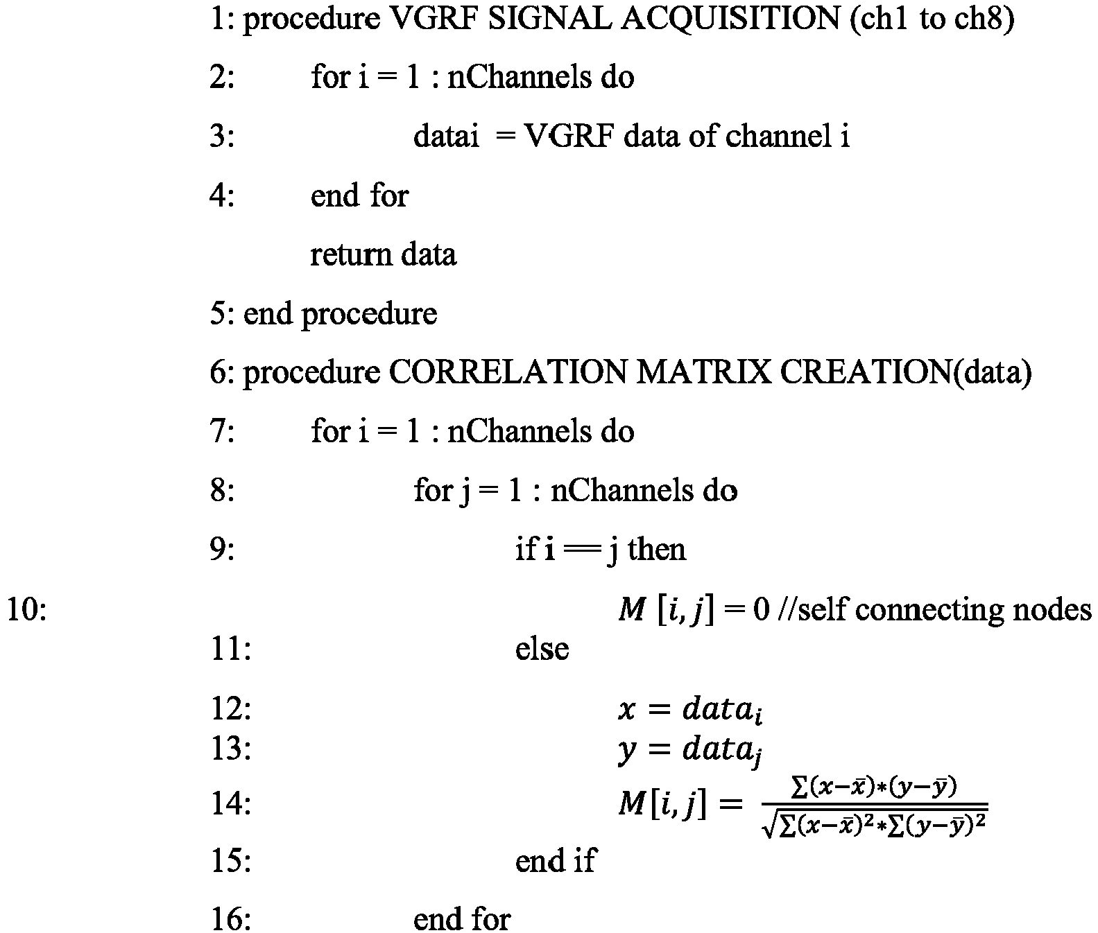

- The written description describes the subject matter herein to enable any person skilled in the art to make and use the embodiments. The scope of the subject matter embodiments is defined by the claims and may include other modifications that occur to those skilled in the art. Such other modifications are intended to be within the scope of the claims if they have similar elements that do not differ from the literal language of the claims or if they include equivalent elements with insubstantial differences from the literal language of the claims.
- The embodiments of present disclosure herein addresses unresolved problem of identifying biomarkers for detecting progression of Parkinson's disease. The embodiment, thus provides graph connectivity approach to derive a novel metric associated with changes in mediolateral pressure distribution based on the VGRF data obtained from the insole. Further, the mediolateral stability index is utilized as a screening index to measure flat footedness of the subject. Moreover, the embodiments herein further provides, a monitoring system for Parkinson's disease.
- It is to be understood that the scope of the protection is extended to such a program and in addition to a computer-readable means having a message therein; such computer-readable storage means contain program-code means for implementation of one or more steps of the method, when the program runs on a server or mobile device or any suitable programmable device. The hardware device can be any kind of device which can be programmed including e.g. any kind of computer like a server or a personal computer, or the like, or any combination thereof. The device may also include means which could be e.g. hardware means like e.g. an application-specific integrated circuit (ASIC), a field-programmable gate array (FPGA), or a combination of hardware and software means, e.g. an ASIC and an FPGA, or at least one microprocessor and at least one memory with software modules located therein. Thus, the means can include both hardware means and software means. The method embodiments described herein could be implemented in hardware and software. The device may also include software means. Alternatively, the embodiments may be implemented on different hardware devices, e.g. using a plurality of CPUs.
- The embodiments herein can comprise hardware and software elements. The embodiments that are implemented in software include but are not limited to, firmware, resident software, microcode, etc. The functions performed by various modules described herein may be implemented in other modules or combinations of other modules. For the purposes of this description, a computer-usable or computer readable medium can be any apparatus that can comprise, store, communicate, propagate, or transport the program for use by or in connection with the instruction execution system, apparatus, or device.
- The illustrated steps are set out to explain the exemplary embodiments shown, and it should be anticipated that ongoing technological development will change the manner in which particular functions are performed. These examples are presented herein for purposes of illustration, and not limitation. Further, the boundaries of the functional building blocks have been arbitrarily defined herein for the convenience of the description. Alternative boundaries can be defined so long as the specified functions and relationships thereof are appropriately performed. Alternatives (including equivalents, extensions, variations, deviations, etc., of those described herein) will be apparent to persons skilled in the relevant art(s) based on the teachings contained herein. Such alternatives fall within the scope and spirit of the disclosed embodiments. Also, the words "comprising," "having," "containing," and "including," and other similar forms are intended to be equivalent in meaning and be open ended in that an item or items following any one of these words is not meant to be an exhaustive listing of such item or items, or meant to be limited to only the listed item or items. It must also be noted that as used herein and in the appended claims, the singular forms "a," "an," and "the" include plural references unless the context clearly dictates otherwise.
- Furthermore, one or more computer-readable storage media may be utilized in implementing embodiments consistent with the present disclosure. A computer-readable storage medium refers to any type of physical memory on which information or data readable by a processor may be stored. Thus, a computer-readable storage medium may store instructions for execution by one or more processors, including instructions for causing the processor(s) to perform steps or stages consistent with the embodiments described herein. The term "computer-readable medium" should be understood to include tangible items and exclude carrier waves and transient signals, i.e., be non-transitory. Examples include random access memory (RAM), read-only memory (ROM), volatile memory, nonvolatile memory, hard drives, CD ROMs, DVDs, flash drives, disks, and any other known physical storage media.
- It is intended that the disclosure and examples be considered as exemplary only, with a true scope and spirit of disclosed embodiments being indicated by the following claims.
Claims (6)
- A processor implemented method for detecting Parkinson's disease progression of a subject, the method comprising:receiving, by a one or more hardware processors, a Vertical Ground Reaction Force (VGRF) data from each of a plurality of pressure sensors attached to an insole;determining, by the one or more hardware processors, a stride information for each of the plurality of pressure sensors from the corresponding VGRF data, wherein each of the plurality of pressure sensors correspond to a plurality of pressure points in a foot of the subject, and each pressure point corresponds to a node in a graph;calculating, by the one or more hardware processors, a mediolateral stability index from the calculated stride information associated with each node in the graph based on a betweenness centrality associated with each node; anddetecting, by the one or more hardware processors, an intensity of the Parkinson's disease of the subject by comparing the mediolateral stability index with a predetermined value.
- The method of claim1, wherein the method of calculating the mediolateral stability index from the calculated stride information associated with each node in the graph based on the betweenness centrality associated with each node comprises:calculating, a Pearson's correlation coefficient associated with each edge from the plurality of edges, connecting a first node and a second node based on the stride information associated with the first node and the stride information associated with the second node, wherein the first node is adjacent to the second node;constructing, a weighted adjacency matrix from the graph based on the Pearson's correlation coefficient associated with each edge from the plurality of edges;calculating, a total number of shortest paths from a source node to a sink node by utilizing the weighted adjacency matrix;calculating, for each node, a number of shortest paths from the source node to the sink node passing through each node by utilizing the weighted adjacency matrix;calculating, a betweenness centrality for each node excluding the source node and the sink node by dividing the number of shortest paths from the source node to the sink node passing through each node by the total number of shortest paths from the source node to the sink node; andcalculating, a mediolateral stability index from the betweenness centrality associated with each node based on a difference between the betweenness centrality associated with each node and a set of adjacent nodes associated with each node.
- The method of claim 1, wherein intensity of the Parkinson's disease of the subject is classified into one of no Parkinson's disease, mild Parkinson's disease, moderate Parkinson's disease and severe Parkinson's disease.
- A system (100) for detecting Parkinson's disease progression of a subject, the system (200) comprising:an insole (124) with a plurality of pressure sensors;at least one memory (204) storing programmed instructions; andat least one hardware processor (202) operatively coupled to the at least one memory, wherein the at least one hardware processor (202) are configured by the programmed instructions to:receive, a Vertical Ground Reaction Force (VGRF) data from each of a plurality of pressure sensors attached to an insole;determine, a stride information for each of the plurality of pressure sensors from the corresponding VGRF data, wherein each of the plurality of pressure sensors correspond to a plurality of pressure points in a foot of the subject, and each pressure point corresponds to a node in a graph;calculate, a mediolateral stability index from the calculated stride information associated with each node in the graph based on a betweenness centrality associated with each node;detect, an intensity of the Parkinson's disease of the subject by comparing the mediolateral stability index with a predetermined value.
- The system of claim 4, wherein the gait dynamics analysis unit is configured to calculate the mediolateral stability index from the calculated stride information associated with each node in the graph based on the betweenness centrality associated with each node by:calculating, a Pearson's correlation coefficient associated with each edge from the plurality of edges, connecting a first node and a second node based on the stride information associated with the first node and the stride information associated with the second node, wherein the first node is adjacent to the second node;constructing, a weighted adjacency matrix from the connectivity graph based on the Pearson's correlation coefficient associated with each edge from the plurality of edges;calculating, a total number of shortest paths from a source node to a sink node by utilizing the weighted adjacency matrix;calculating, for each node, a number of shortest paths from the source node to the sink node passing through each node by utilizing the weighted adjacency matrix;calculating, a betweenness centrality for each node excluding the source node and the sink node by dividing the number of shortest paths from the source node to the sink node passing through each node by the total number of shortest paths from the source node to the sink node;calculating, a mediolateral stability index from the betweenness centrality associated with each node based on a difference between the betweenness centrality associated with each node and a set of adjacent nodes associated with each node;
- The system of claim 4, wherein intensity of the Parkinson's disease of the subject is classified into one of no Parkinson's disease, mild Parkinson's disease, moderate Parkinson's disease and severe Parkinson's disease.
Applications Claiming Priority (1)
| Application Number | Priority Date | Filing Date | Title |
|---|---|---|---|
| IN201921007036 | 2019-02-22 |
Publications (3)
| Publication Number | Publication Date |
|---|---|
| EP3699928A1 true EP3699928A1 (en) | 2020-08-26 |
| EP3699928B1 EP3699928B1 (en) | 2024-07-17 |
| EP3699928C0 EP3699928C0 (en) | 2024-07-17 |
Family
ID=69804418
Family Applications (1)
| Application Number | Title | Priority Date | Filing Date |
|---|---|---|---|
| EP20158482.8A Active EP3699928B1 (en) | 2019-02-22 | 2020-02-20 | Method and system for detecting parkinson's disease |
Country Status (2)
| Country | Link |
|---|---|
| US (1) | US11517247B2 (en) |
| EP (1) | EP3699928B1 (en) |
Cited By (2)
| Publication number | Priority date | Publication date | Assignee | Title |
|---|---|---|---|---|
| CN113143251A (en) * | 2021-01-28 | 2021-07-23 | 胤迈医药科技(上海)有限公司 | Household wearable device based on stride monitoring |
| CN117582213A (en) * | 2024-01-18 | 2024-02-23 | 佳木斯大学 | Wearable equipment for quantifying and identifying parkinsonism dyskinesia |
Families Citing this family (1)
| Publication number | Priority date | Publication date | Assignee | Title |
|---|---|---|---|---|
| US11874732B2 (en) * | 2021-09-24 | 2024-01-16 | Bmc Software, Inc. | Recommendations for remedial actions |
Family Cites Families (4)
| Publication number | Priority date | Publication date | Assignee | Title |
|---|---|---|---|---|
| US8823526B2 (en) * | 2009-07-02 | 2014-09-02 | The Regents Of The University Of California | Method of assessing human fall risk using mobile systems |
| US9265441B2 (en) * | 2013-07-12 | 2016-02-23 | Siemens Aktiengesellschaft | Assessment of traumatic brain injury |
| US10405779B2 (en) * | 2015-01-07 | 2019-09-10 | Nano Composite Products, Inc. | Shoe-based analysis system |
| TWI629012B (en) | 2016-02-24 | 2018-07-11 | 國立清華大學 | Intelligent insole |
-
2020
- 2020-02-20 EP EP20158482.8A patent/EP3699928B1/en active Active
- 2020-02-21 US US16/796,972 patent/US11517247B2/en active Active
Non-Patent Citations (4)
| Title |
|---|
| EGUCHI RYO ET AL: "Accessible ground reaction force estimation using insole force sensors without force plates", 2017 11TH ASIAN CONTROL CONFERENCE (ASCC), IEEE, 17 December 2017 (2017-12-17), pages 2861 - 2865, XP033314811, DOI: 10.1109/ASCC.2017.8287631 * |
| JIAXIN MA ET AL: "Optimizing Gait Parameters and Insole Sensor Positioning for Parkinson's Disease Assessment", BIOMEDICAL AND BIOINFORMATICS ENGINEERING, ACM, 2 PENN PLAZA, SUITE 701NEW YORKNY10121-0701USA, 12 November 2017 (2017-11-12), pages 43 - 47, XP058381681, ISBN: 978-1-4503-5484-4, DOI: 10.1145/3168776.3168780 * |
| LEE JIHUI ET AL: "Functional Data Analyses of Gait Data Measured Using In-Shoe Sensors", STATISTICS IN BIOSCIENCES, SPRINGER US, BOSTON, vol. 11, no. 2, 7 December 2018 (2018-12-07), pages 288 - 313, XP036849145, ISSN: 1867-1764, [retrieved on 20181207], DOI: 10.1007/S12561-018-9226-3 * |
| MAZUMDER OISHEE ET AL: "Assessment of Insole Based Gait Feature Variation with Progression of Parkinson's Disease", 2018 IEEE SENSORS, IEEE, 28 October 2018 (2018-10-28), pages 1 - 4, XP033477368, DOI: 10.1109/ICSENS.2018.8589635 * |
Cited By (3)
| Publication number | Priority date | Publication date | Assignee | Title |
|---|---|---|---|---|
| CN113143251A (en) * | 2021-01-28 | 2021-07-23 | 胤迈医药科技(上海)有限公司 | Household wearable device based on stride monitoring |
| CN117582213A (en) * | 2024-01-18 | 2024-02-23 | 佳木斯大学 | Wearable equipment for quantifying and identifying parkinsonism dyskinesia |
| CN117582213B (en) * | 2024-01-18 | 2024-04-02 | 佳木斯大学 | Wearable equipment for quantifying and identifying parkinsonism dyskinesia |
Also Published As
| Publication number | Publication date |
|---|---|
| US20200268306A1 (en) | 2020-08-27 |
| US11517247B2 (en) | 2022-12-06 |
| EP3699928B1 (en) | 2024-07-17 |
| EP3699928C0 (en) | 2024-07-17 |
Similar Documents
| Publication | Publication Date | Title |
|---|---|---|
| EP3699928B1 (en) | Method and system for detecting parkinson's disease | |
| US10743819B2 (en) | System and method for determining information and outliers from sensor data | |
| Salem et al. | Markov models for anomaly detection in wireless body area networks for secure health monitoring | |
| Casilari et al. | Analysis of a smartphone-based architecture with multiple mobility sensors for fall detection | |
| JP6856568B2 (en) | Methods and systems for postural stability evaluation | |
| US20160296144A1 (en) | Time and frequency domain based activity tracking system | |
| EP3572980A1 (en) | Method and system for joint selection of a feature subset-classifier pair for a classification task | |
| US20130023798A1 (en) | Method for body-worn sensor based prospective evaluation of falls risk in community-dwelling elderly adults | |
| US10909503B1 (en) | Snapshots to train prediction models and improve workflow execution | |
| US8823526B2 (en) | Method of assessing human fall risk using mobile systems | |
| Yu et al. | A scalable, non-parametric method for detecting performance anomaly in large scale computing | |
| US10733264B2 (en) | System and method for detecting outliers in real-time for a univariate time-series signal | |
| US20230112071A1 (en) | Assessing fall risk of mobile device user | |
| CN110169774B (en) | Motion state identification system and method based on block chain | |
| WO2013128972A1 (en) | Movement determination device, movement determination system and movement determination method | |
| Dimoudis et al. | Utilizing an adaptive window rolling median methodology for time series anomaly detection | |
| US20180255879A1 (en) | Receiving feedback based on pressure sensor data and movement data | |
| Hemmatpour et al. | Nonlinear Predictive Threshold Model for Real‐Time Abnormal Gait Detection | |
| CN109976986B (en) | Abnormal equipment detection methods and devices | |
| US11593469B2 (en) | Continuously validating a user during an established authenticated session using photoplethysmogram and accelerometer data | |
| Koffman et al. | Evaluating step counting algorithms on subsecond wrist-worn accelerometry: a comparison using publicly available data sets | |
| Rajendran et al. | Anomaly detection at wireless body area network coordinators for telemedicine | |
| Kumar et al. | Notice of violation of IEEE publication principles: affirmative fusion process for improving wearable sensor data availability in artificial intelligence of medical things | |
| Pilkar et al. | Performance analyses of step-counting algorithms using wrist accelerometry | |
| EP3903673B1 (en) | Blood pressure estimation with photoplethysmography measurement |
Legal Events
| Date | Code | Title | Description |
|---|---|---|---|
| PUAI | Public reference made under article 153(3) epc to a published international application that has entered the european phase |
Free format text: ORIGINAL CODE: 0009012 |
|
| STAA | Information on the status of an ep patent application or granted ep patent |
Free format text: STATUS: THE APPLICATION HAS BEEN PUBLISHED |
|
| AK | Designated contracting states |
Kind code of ref document: A1 Designated state(s): AL AT BE BG CH CY CZ DE DK EE ES FI FR GB GR HR HU IE IS IT LI LT LU LV MC MK MT NL NO PL PT RO RS SE SI SK SM TR |
|
| AX | Request for extension of the european patent |
Extension state: BA ME |
|
| STAA | Information on the status of an ep patent application or granted ep patent |
Free format text: STATUS: REQUEST FOR EXAMINATION WAS MADE |
|
| 17P | Request for examination filed |
Effective date: 20210226 |
|
| RBV | Designated contracting states (corrected) |
Designated state(s): AL AT BE BG CH CY CZ DE DK EE ES FI FR GB GR HR HU IE IS IT LI LT LU LV MC MK MT NL NO PL PT RO RS SE SI SK SM TR |
|
| STAA | Information on the status of an ep patent application or granted ep patent |
Free format text: STATUS: EXAMINATION IS IN PROGRESS |
|
| 17Q | First examination report despatched |
Effective date: 20230704 |
|
| GRAP | Despatch of communication of intention to grant a patent |
Free format text: ORIGINAL CODE: EPIDOSNIGR1 |
|
| STAA | Information on the status of an ep patent application or granted ep patent |
Free format text: STATUS: GRANT OF PATENT IS INTENDED |
|
| RIC1 | Information provided on ipc code assigned before grant |
Ipc: A61B 5/103 20060101ALI20240122BHEP Ipc: A61B 5/11 20060101ALI20240122BHEP Ipc: A61B 5/00 20060101ALI20240122BHEP Ipc: G16H 50/70 20180101ALI20240122BHEP Ipc: G16H 50/30 20180101ALI20240122BHEP Ipc: G16H 50/20 20180101AFI20240122BHEP |
|
| INTG | Intention to grant announced |
Effective date: 20240209 |
|
| GRAS | Grant fee paid |
Free format text: ORIGINAL CODE: EPIDOSNIGR3 |
|
| GRAA | (expected) grant |
Free format text: ORIGINAL CODE: 0009210 |
|
| STAA | Information on the status of an ep patent application or granted ep patent |
Free format text: STATUS: THE PATENT HAS BEEN GRANTED |
|
| AK | Designated contracting states |
Kind code of ref document: B1 Designated state(s): AL AT BE BG CH CY CZ DE DK EE ES FI FR GB GR HR HU IE IS IT LI LT LU LV MC MK MT NL NO PL PT RO RS SE SI SK SM TR |
|
| REG | Reference to a national code |
Ref country code: CH Ref legal event code: EP |
|
| REG | Reference to a national code |
Ref country code: DE Ref legal event code: R096 Ref document number: 602020033959 Country of ref document: DE |
|
| REG | Reference to a national code |
Ref country code: IE Ref legal event code: FG4D |
|
| U01 | Request for unitary effect filed |
Effective date: 20240717 |
|
| U07 | Unitary effect registered |
Designated state(s): AT BE BG DE DK EE FI FR IT LT LU LV MT NL PT SE SI Effective date: 20240724 |
|
| PG25 | Lapsed in a contracting state [announced via postgrant information from national office to epo] |
Ref country code: NO Free format text: LAPSE BECAUSE OF FAILURE TO SUBMIT A TRANSLATION OF THE DESCRIPTION OR TO PAY THE FEE WITHIN THE PRESCRIBED TIME-LIMIT Effective date: 20241017 |
|
| PG25 | Lapsed in a contracting state [announced via postgrant information from national office to epo] |
Ref country code: PL Free format text: LAPSE BECAUSE OF FAILURE TO SUBMIT A TRANSLATION OF THE DESCRIPTION OR TO PAY THE FEE WITHIN THE PRESCRIBED TIME-LIMIT Effective date: 20240717 Ref country code: GR Free format text: LAPSE BECAUSE OF FAILURE TO SUBMIT A TRANSLATION OF THE DESCRIPTION OR TO PAY THE FEE WITHIN THE PRESCRIBED TIME-LIMIT Effective date: 20241018 |
|
| PG25 | Lapsed in a contracting state [announced via postgrant information from national office to epo] |
Ref country code: IS Free format text: LAPSE BECAUSE OF FAILURE TO SUBMIT A TRANSLATION OF THE DESCRIPTION OR TO PAY THE FEE WITHIN THE PRESCRIBED TIME-LIMIT Effective date: 20241117 |
|
| PG25 | Lapsed in a contracting state [announced via postgrant information from national office to epo] |
Ref country code: HR Free format text: LAPSE BECAUSE OF FAILURE TO SUBMIT A TRANSLATION OF THE DESCRIPTION OR TO PAY THE FEE WITHIN THE PRESCRIBED TIME-LIMIT Effective date: 20240717 |
|
| PG25 | Lapsed in a contracting state [announced via postgrant information from national office to epo] |
Ref country code: ES Free format text: LAPSE BECAUSE OF FAILURE TO SUBMIT A TRANSLATION OF THE DESCRIPTION OR TO PAY THE FEE WITHIN THE PRESCRIBED TIME-LIMIT Effective date: 20240717 Ref country code: RS Free format text: LAPSE BECAUSE OF FAILURE TO SUBMIT A TRANSLATION OF THE DESCRIPTION OR TO PAY THE FEE WITHIN THE PRESCRIBED TIME-LIMIT Effective date: 20241017 |
|
| PG25 | Lapsed in a contracting state [announced via postgrant information from national office to epo] |
Ref country code: RS Free format text: LAPSE BECAUSE OF FAILURE TO SUBMIT A TRANSLATION OF THE DESCRIPTION OR TO PAY THE FEE WITHIN THE PRESCRIBED TIME-LIMIT Effective date: 20241017 Ref country code: PL Free format text: LAPSE BECAUSE OF FAILURE TO SUBMIT A TRANSLATION OF THE DESCRIPTION OR TO PAY THE FEE WITHIN THE PRESCRIBED TIME-LIMIT Effective date: 20240717 Ref country code: NO Free format text: LAPSE BECAUSE OF FAILURE TO SUBMIT A TRANSLATION OF THE DESCRIPTION OR TO PAY THE FEE WITHIN THE PRESCRIBED TIME-LIMIT Effective date: 20241017 Ref country code: IS Free format text: LAPSE BECAUSE OF FAILURE TO SUBMIT A TRANSLATION OF THE DESCRIPTION OR TO PAY THE FEE WITHIN THE PRESCRIBED TIME-LIMIT Effective date: 20241117 Ref country code: HR Free format text: LAPSE BECAUSE OF FAILURE TO SUBMIT A TRANSLATION OF THE DESCRIPTION OR TO PAY THE FEE WITHIN THE PRESCRIBED TIME-LIMIT Effective date: 20240717 Ref country code: GR Free format text: LAPSE BECAUSE OF FAILURE TO SUBMIT A TRANSLATION OF THE DESCRIPTION OR TO PAY THE FEE WITHIN THE PRESCRIBED TIME-LIMIT Effective date: 20241018 Ref country code: ES Free format text: LAPSE BECAUSE OF FAILURE TO SUBMIT A TRANSLATION OF THE DESCRIPTION OR TO PAY THE FEE WITHIN THE PRESCRIBED TIME-LIMIT Effective date: 20240717 |
|
| U20 | Renewal fee for the european patent with unitary effect paid |
Year of fee payment: 6 Effective date: 20250224 |
|
| PG25 | Lapsed in a contracting state [announced via postgrant information from national office to epo] |
Ref country code: SM Free format text: LAPSE BECAUSE OF FAILURE TO SUBMIT A TRANSLATION OF THE DESCRIPTION OR TO PAY THE FEE WITHIN THE PRESCRIBED TIME-LIMIT Effective date: 20240717 |
|
| PG25 | Lapsed in a contracting state [announced via postgrant information from national office to epo] |
Ref country code: CZ Free format text: LAPSE BECAUSE OF FAILURE TO SUBMIT A TRANSLATION OF THE DESCRIPTION OR TO PAY THE FEE WITHIN THE PRESCRIBED TIME-LIMIT Effective date: 20240717 |
|
| PG25 | Lapsed in a contracting state [announced via postgrant information from national office to epo] |
Ref country code: SK Free format text: LAPSE BECAUSE OF FAILURE TO SUBMIT A TRANSLATION OF THE DESCRIPTION OR TO PAY THE FEE WITHIN THE PRESCRIBED TIME-LIMIT Effective date: 20240717 |
|
| PLBE | No opposition filed within time limit |
Free format text: ORIGINAL CODE: 0009261 |
|
| STAA | Information on the status of an ep patent application or granted ep patent |
Free format text: STATUS: NO OPPOSITION FILED WITHIN TIME LIMIT |
|
| 26N | No opposition filed |
Effective date: 20250422 |
|
| PG25 | Lapsed in a contracting state [announced via postgrant information from national office to epo] |
Ref country code: MC Free format text: LAPSE BECAUSE OF FAILURE TO SUBMIT A TRANSLATION OF THE DESCRIPTION OR TO PAY THE FEE WITHIN THE PRESCRIBED TIME-LIMIT Effective date: 20240717 |
|
| PG25 | Lapsed in a contracting state [announced via postgrant information from national office to epo] |
Ref country code: IE Free format text: LAPSE BECAUSE OF NON-PAYMENT OF DUE FEES Effective date: 20250220 |
|
| REG | Reference to a national code |
Ref country code: CH Ref legal event code: U11 Free format text: ST27 STATUS EVENT CODE: U-0-0-U10-U11 (AS PROVIDED BY THE NATIONAL OFFICE) Effective date: 20260301 |
|
| U20 | Renewal fee for the european patent with unitary effect paid |
Year of fee payment: 7 Effective date: 20260224 |
|
| PGFP | Annual fee paid to national office [announced via postgrant information from national office to epo] |
Ref country code: GB Payment date: 20260223 Year of fee payment: 7 |
|
| PG25 | Lapsed in a contracting state [announced via postgrant information from national office to epo] |
Ref country code: RO Free format text: LAPSE BECAUSE OF FAILURE TO SUBMIT A TRANSLATION OF THE DESCRIPTION OR TO PAY THE FEE WITHIN THE PRESCRIBED TIME-LIMIT Effective date: 20240717 |
|
| PGFP | Annual fee paid to national office [announced via postgrant information from national office to epo] |
Ref country code: CH Payment date: 20260301 Year of fee payment: 7 |