EP3699893B1 - Led display module - Google Patents
Led display module Download PDFInfo
- Publication number
- EP3699893B1 EP3699893B1 EP20155550.5A EP20155550A EP3699893B1 EP 3699893 B1 EP3699893 B1 EP 3699893B1 EP 20155550 A EP20155550 A EP 20155550A EP 3699893 B1 EP3699893 B1 EP 3699893B1
- Authority
- EP
- European Patent Office
- Prior art keywords
- led display
- rear plate
- display module
- module according
- clamping strip
- Prior art date
- Legal status (The legal status is an assumption and is not a legal conclusion. Google has not performed a legal analysis and makes no representation as to the accuracy of the status listed.)
- Active
Links
Images

Classifications
-
- H—ELECTRICITY
- H05—ELECTRIC TECHNIQUES NOT OTHERWISE PROVIDED FOR
- H05K—PRINTED CIRCUITS; CASINGS OR CONSTRUCTIONAL DETAILS OF ELECTRIC APPARATUS; MANUFACTURE OF ASSEMBLAGES OF ELECTRICAL COMPONENTS
- H05K5/00—Casings, cabinets or drawers for electric apparatus
- H05K5/0017—Casings, cabinets or drawers for electric apparatus with operator interface units
-
- G—PHYSICS
- G09—EDUCATION; CRYPTOGRAPHY; DISPLAY; ADVERTISING; SEALS
- G09F—DISPLAYING; ADVERTISING; SIGNS; LABELS OR NAME-PLATES; SEALS
- G09F9/00—Indicating arrangements for variable information in which the information is built-up on a support by selection or combination of individual elements
- G09F9/30—Indicating arrangements for variable information in which the information is built-up on a support by selection or combination of individual elements in which the desired character or characters are formed by combining individual elements
- G09F9/302—Indicating arrangements for variable information in which the information is built-up on a support by selection or combination of individual elements in which the desired character or characters are formed by combining individual elements characterised by the form or geometrical disposition of the individual elements
- G09F9/3026—Video wall, i.e. stackable semiconductor matrix display modules
-
- H—ELECTRICITY
- H05—ELECTRIC TECHNIQUES NOT OTHERWISE PROVIDED FOR
- H05K—PRINTED CIRCUITS; CASINGS OR CONSTRUCTIONAL DETAILS OF ELECTRIC APPARATUS; MANUFACTURE OF ASSEMBLAGES OF ELECTRICAL COMPONENTS
- H05K5/00—Casings, cabinets or drawers for electric apparatus
- H05K5/02—Details
- H05K5/0204—Mounting supporting structures on the outside of casings
-
- H—ELECTRICITY
- H05—ELECTRIC TECHNIQUES NOT OTHERWISE PROVIDED FOR
- H05K—PRINTED CIRCUITS; CASINGS OR CONSTRUCTIONAL DETAILS OF ELECTRIC APPARATUS; MANUFACTURE OF ASSEMBLAGES OF ELECTRICAL COMPONENTS
- H05K5/00—Casings, cabinets or drawers for electric apparatus
- H05K5/02—Details
- H05K5/0217—Mechanical details of casings
- H05K5/023—Handles; Grips
-
- H—ELECTRICITY
- H05—ELECTRIC TECHNIQUES NOT OTHERWISE PROVIDED FOR
- H05K—PRINTED CIRCUITS; CASINGS OR CONSTRUCTIONAL DETAILS OF ELECTRIC APPARATUS; MANUFACTURE OF ASSEMBLAGES OF ELECTRICAL COMPONENTS
- H05K5/00—Casings, cabinets or drawers for electric apparatus
- H05K5/02—Details
- H05K5/0247—Electrical details of casings, e.g. terminals, passages for cables or wiring
-
- H—ELECTRICITY
- H10—SEMICONDUCTOR DEVICES; ELECTRIC SOLID-STATE DEVICES NOT OTHERWISE PROVIDED FOR
- H10W—GENERIC PACKAGES, INTERCONNECTIONS, CONNECTORS OR OTHER CONSTRUCTIONAL DETAILS OF DEVICES COVERED BY CLASS H10
- H10W90/00—Package configurations
Definitions
- the present application relates to the technical field of LED display screens, in particular to a LED display module configured to form a LED display screen.
- the existing LED display module includes a rear plate and a plurality of light bars installed on the rear plate.
- a clamping strip with a plurality of clamping slots for limiting the light bars is generally provided on the rear plate to ensure the distance between adjacent light bars, and the clamping slots are provided corresponding to the light bars one by one.
- CN 204884455U discloses a LED glass curtain wall screen, includes frame and a plurality of LED side surface lamp strip, a plurality of LED side surface lamp strips separate the certain distance setting each other on the frame, the LED side surface lamp strip includes PCB board and more than one LED lamp, be equipped with the circuit on the PCB board, be provided with positive connecting terminal of more than one and more than one back connecting terminal respectively on the corresponding position in the front of PCB board and the back, positive connecting terminal and back connecting terminal respectively with circuit electric connection, the LED lamp sets up on the side of PCB board, and the first welding foot of LED lamp and second welding foot weld with positive connecting terminal with back connecting terminal that positive connecting terminal corresponds respectively, circuit and LED lamp constitute glow loops.
- the utility model discloses owing to adopted frame and a plurality of LED side surface lamp strip, a plurality of LED side surface lamp strips separate the certain distance setting each other and on the frame, set up the LED lamp on the side of PCB board, have simple structure, light in weight, luminousness high, install and demolish all advantage such as very convenient, pleasing to the eye and decoration.
- the object of the present application is to provide a LED display module which is easy to carry.
- the present application provides a LED display module, which is configured to form a LED display screen as defined in claim 1.
- Advantageous embodiments are set out in the dependent claims.
- Reference numeral Name Reference numeral Name 1 Rear plate 10 Adapter board 2 Clamping strip 11 Interface 3 Light bar 12 Slot 4 Clamping slot 13 Side fixing board 5 Handle 14 Positioning hole 6 Through hole 15 Front plate 7 Ventilation hole 16 Gap 8 First slot 17 Positioning column 9 Second slot 18 Weight reduction slot
- a handle is provided on a LED display module, which is convenient for user to carry and maintain.
- the handle is connected with the clamping strip, which may prevent the LED display module from being accidentally damaged during transportation.
- a LED display module includes a rear plate 1; at least one clamping strip 2 including a plurality of clamping slots 4; and a plurality of light bars 3 limited by the plurality of clamping slots 4.
- the clamping strip 2 includes a handle 5, and the rear plate 1 includes at least one through hole 6 configured for the handle 5 to pass through.
- the beneficial effect of the present application is that the LED display module includes a handle 5, which is convenient for the user to carry and maintain.
- the local area of the clamping strip 2 may be able to withstand greater shear forces compared to the rear plate 1.
- the handle 5 connecting with the clamping strip 2 may ensure the structural stability of the LED display module, and the LED display module may be not easily damaged during transportation.
- handle 5 and the clamping strip 2 are integrally formed.
- the handle 5 and the clamping strip 2 are integrally formed, which facilitates processing and reducing manufacturing costs.
- the rear plate 1 includes at least one ventilation hole 7.
- the ventilation performance of the LED display module may be enhanced by defining at least one ventilation hole 7 on the rear plate.
- At least one of the light bars 3 is abutted against the rear plate 1, and at least one of the light bars 3 includes a first slot 8 configured to avoid the clamping strip 2.
- one side of at least one of the clamping slots 4 includes a second slot 9.
- the second slot 9 communicating with the clamping slot 4 is configured to provide a space to avoid the components (such as lamp beads) on the light bar 3.
- the LED display module further includes an adapter board 10 fixed on the rear plate 1, and one end of each light bar 3 is fixed and electrically connected to the adapter board 10.
- the adapter board 10 includes at least one interface 11.
- the rear plate 1 includes at least one slot 12 configured to expose the at least one interface 11.
- the LED display module may be in electrical connection and signal connection with the display cabinet through the above interface.
- the LED display module further includes a side fixing board 13, and the other end of each light bar 3 is fixed on the side fixing board 13.
- the side fixing board 13, the light bar 3 and the adapter board 10 form a fence structure, which facilitates further improving the structural stability of the LED display module.
- the rear plate 1 and the adapter board 10 both include at least one positioning hole 14, and the at least one positioning hole 14 defined at the rear plate 1 are aligned with the at least one positioning hole 14 defined at the adapter board 10.
- the LED display module further includes a front plate 15 fixedly connected with the rear plate 1.
- the light bars 3 and the clamping strip 2 are located between the front plate 15 and the rear plate 1.
- a lateral side of the clamping strip 2 away from the rear plate 1 is abutted against the front plate 15.
- a gap 16 is defined between each light bar 3 and the front plate 15.
- the structural stability of the LED display module may be further improved by the clamping strip 2 being abutted against the front plate 15.
- the gap 16 between each light bar 3 and the front plate 15 may provide sufficient protection for the lamp beads on the light bar 3.
- a side of the rear plate 1 adjacent to the front plate 15 is provided with a plurality of positioning columns 17, and the plurality of positioning columns 17 are abutted against the front plate 15.
- the distance between the front plate 15 and the rear plate 1 may be ensured by the positioning columns 17, so that the front plate 15 may be adequately supported, and the structure of the LED display module may be more stable.
- a LED display module includes a rear plate 1; at least one clamping strip 2 including a plurality of clamping slots 4; and a plurality of light bars 3 limited by the plurality of clamping slots 4 fixed on the rear plate 1 by the clamping strip 2.
- the clamping strip 2 includes a handle 5, and the rear plate 1 includes at least one through hole 6 configured for the handle 5 to pass through.
- the handle 5 and the clamping strip 2 are integrally formed.
- the handle 5 and the clamping strip 2 are integrally injection-molded. It is easy to understand that it is also feasible to dispose the handle 5 and the clamping strip 2 separately, and the handle 5 and the clamping strip 2 provided separately may be screwed, glued or clamped.
- the rear plate 1 is further provided with at least one ventilation hole 7.
- At least one of the light bar 3 is abutted against the rear plate 1.
- at least one of the light bars 3 is provided with a first slot 8 configured to provide a space to avoid the clamping strip 2, and one side of at least one of the clamping slots 4 is provided with a second slot 9.
- the LED display module includes an adapter board 10 fixed on the rear plate 1, and one end of each light bar 3 is fixed and electrically connected to the adapter board 10. At least one interface 11 is provided on the adapter board 10. At least one slot 12 configured to expose the at least one interface 11 is provided on the rear plate 1.
- the LED display module further includes a side fixing board 13, and the other end of each light bar 3 is fixed on the side fixing board 13.
- the side fixing board 13 is fixedly connected with the rear plate 1.
- an engaging structure is respectively provided between the side fixing board 13 and the light bar 3 and between the adapter board 10 and the light bar 3, and the engaging structure includes, but is not limited to, an engaging notch. The engaging structure may make the connection between the light bar 3 and the adapter board 10 and the light bar 3 and the side fixing board 13 more stable.
- At least one positioning hole 14 is respectively provided at the rear plate 1 and the adapter board 10, and the at least one positioning hole 14 defined at the rear plate 1 is aligned with the at least one positioning hole 14 defined at the adapter board 10 one by one.
- the at least one positioning hole 14 is located at four corners of the rear plate 1.
- the rear plate 1 is further provided with mounting members connected with the external component.
- the mounting members are mounting screw holes.
- the LED display module further includes a front plate 15 fixedly connected with the rear plate 1.
- the light bars 3 and the clamping strip 2 are located between the front plate 15 and the rear plate 1.
- a lateral side of the clamping strip 2 away from the rear plate 1 is abutted against the front plate 15.
- a gap 16 is defined between each light bar 3 and the front plate 15.
- a side of the rear plate 1 adjacent to the front plate 15 is provided with a plurality of positioning columns 17, and the plurality of positioning columns 17 are abutted against the front plate 15. More specifically, one end of the positioning column 17 away from the rear plate 1 is provided with a screw hole, and the front plate 15 is fixed with the positioning column 17 by a screw being engaged with the screw hole so as to be connected and fixed with the rear plate 1.
- the length of the positioning column 17 is not less than the thickness of the clamping strip 2.
- the length of the positioning column 17 is equal to the thickness of the clamping strip 2. In this way, two opposite lateral sides of the clamping strip 2 are abutted against the front plate 15 and the rear plate 1 respectively, which facilitates enhancing the stability of the structure of the LED display module.
- the clamping strip 2 is provided with a plurality of weight reduction slots 18.
- the front plate 15 and the rear plate 1 are transparent plates, and the material of the transparent plate may be PC.
- the clamping strip 2 and the handle 5 are made of transparent materials, and the transparent material may be PC.
- the LED display module provided by the present application includes a handle which is convenient for the user to carry and maintain.
- the structure is stable, and the LED display module is not easy to be damaged during transportation.
- the handle and the clamping strip are integrally formed, which facilitates processing and reducing manufacturing costs.
- the ventilation performance of the LED display module may be enhanced by defining at least one ventilation hole on the rear plate.
- the LED display module includes an adapter board 10 fixed on the rear plate 1, and one end of each light bar 3 is fixed and electrically connected to the adapter board 10. At least one interface 11 is provided on the adapter board 10. At least one slot 12 configured to expose the at least one interface 11 is provided on the rear plate 1.
- the LED display module further includes a side fixing board 13, and the other end of each light bar 3 is fixed on the side fixing board 13.
- the side fixing board 13 is fixedly connected with the rear plate 1.
- an engaging structure is respectively provided between the side fixing board 13 and the light bar 3 and between the adapter board 10 and the light bar 3, and the engaging structure includes, but is not limited to, an engaging notch. The engaging structure may make the connection between the light bar 3 and the adapter board 10 and the light bar 3 and the side fixing board 13 more stable.
- At least one positioning hole 14 is respectively provided at the rear plate 1 and the adapter board 10, and the at least one positioning hole 14 defined at the rear plate 1 is aligned with the at least one positioning hole 14 defined at the adapter board 10 one by one.
- the at least one positioning hole 14 is located at four corners of the rear plate 1.
- the rear plate 1 is further provided with mounting members connected with the external component.
- the mounting members are mounting screw holes.
- the LED display module further includes a front plate 15 fixedly connected with the rear plate 1.
- the light bars 3 and the clamping strip 2 are located between the front plate 15 and the rear plate 1.
- a lateral side of the clamping strip 2 away from the rear plate 1 is abutted against the front plate 15.
- a gap 16 is defined between each light bar 3 and the front plate 15.
- a side of the rear plate 1 adjacent to the front plate 15 is provided with a plurality of positioning columns 17, and the plurality of positioning columns 17 are abutted against the front plate 15. More specifically, one end of the positioning column 17 away from the rear plate 1 is provided with a screw hole, and the front plate 15 is fixed with the positioning column 17 by a screw being engaged with the screw hole so as to be connected and fixed with the rear plate 1.
- the length of the positioning column 17 is not less than the thickness of the clamping strip 2.
- the length of the positioning column 17 is equal to the thickness of the clamping strip 2. In this way, two opposite lateral sides of the clamping strip 2 are abutted against the front plate 15 and the rear plate 1 respectively, which facilitates enhancing the stability of the structure of the LED display module.
- the clamping strip 2 is provided with a plurality of weight reduction slots 18.
- the front plate 15 and the rear plate 1 are transparent plates, and the material of the transparent plate may be PC.
- the clamping strip 2 and the handle 5 are made of transparent materials, and the transparent material may be PC.
- the LED display module provided by the present application includes a handle which is convenient for the user to carry and maintain.
- the structure is stable, and the LED display module is not easy to be damaged during transportation.
- the handle and the clamping strip are integrally formed, which facilitates processing and reducing manufacturing costs.
- the ventilation performance of the LED display module may be enhanced by defining at least one ventilation hole on the rear plate.
Landscapes
- Engineering & Computer Science (AREA)
- Microelectronics & Electronic Packaging (AREA)
- Multimedia (AREA)
- Physics & Mathematics (AREA)
- General Physics & Mathematics (AREA)
- Theoretical Computer Science (AREA)
- Illuminated Signs And Luminous Advertising (AREA)
- Devices For Indicating Variable Information By Combining Individual Elements (AREA)
Description
- The present application relates to the technical field of LED display screens, in particular to a LED display module configured to form a LED display screen.
- The existing LED display module includes a rear plate and a plurality of light bars installed on the rear plate. A clamping strip with a plurality of clamping slots for limiting the light bars is generally provided on the rear plate to ensure the distance between adjacent light bars, and the clamping slots are provided corresponding to the light bars one by one.
-
CN 204884455U discloses a LED glass curtain wall screen, includes frame and a plurality of LED side surface lamp strip, a plurality of LED side surface lamp strips separate the certain distance setting each other on the frame, the LED side surface lamp strip includes PCB board and more than one LED lamp, be equipped with the circuit on the PCB board, be provided with positive connecting terminal of more than one and more than one back connecting terminal respectively on the corresponding position in the front of PCB board and the back, positive connecting terminal and back connecting terminal respectively with circuit electric connection, the LED lamp sets up on the side of PCB board, and the first welding foot of LED lamp and second welding foot weld with positive connecting terminal with back connecting terminal that positive connecting terminal corresponds respectively, circuit and LED lamp constitute glow loops. The utility model discloses owing to adopted frame and a plurality of LED side surface lamp strip, a plurality of LED side surface lamp strips separate the certain distance setting each other and on the frame, set up the LED lamp on the side of PCB board, have simple structure, light in weight, luminousness high, install and demolish all advantage such as very convenient, pleasing to the eye and decoration. - While there's no point of application of force for the user to assemble the existing LED display module, and it is inconvenient for the user to carry it.
- The object of the present application is to provide a LED display module which is easy to carry.
- In order to achieve the above object, the present application provides a LED display module, which is configured to form a LED display screen as defined in
claim 1. Advantageous embodiments are set out in the dependent claims. -
-
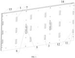
FIG. 1 is a schematic view of an overall structure of a LED display module according to an embodiment of the present application; -
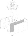
FIG. 2 is a cross-sectional view of the LED display module according to an embodiment of the present application; -
FIG. 3 is an enlarged view of a portion A inFIG. 2 ; -
FIG. 4 is an exploded view of the LED display module according to an embodiment of the present application; and -
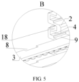
FIG. 5 is an enlarged view of a portion B inFIG. 4 . -
Reference numeral Name Reference numeral Name 1 Rear plate 10 Adapter board 2 Clamping strip 11 Interface 3 Light bar 12 Slot 4 Clamping slot 13 Side fixing board 5 Handle 14 Positioning hole 6 Through hole 15 Front plate 7 Ventilation hole 16 Gap 8 First slot 17 Positioning column 9 Second slot 18 Weight reduction slot - In order to explain in detail the technical content, the achieved object, and effects of the present application, the following description will be made in conjunction with the embodiments and the accompanying drawings.
- The most key idea of the present application is that a handle is provided on a LED display module, which is convenient for user to carry and maintain. The handle is connected with the clamping strip, which may prevent the LED display module from being accidentally damaged during transportation.
- Referring to
FIG. 1 to FIG. 5 , a LED display module includes arear plate 1; at least oneclamping strip 2 including a plurality ofclamping slots 4; and a plurality oflight bars 3 limited by the plurality ofclamping slots 4. Theclamping strip 2 includes ahandle 5, and therear plate 1 includes at least one throughhole 6 configured for thehandle 5 to pass through. - As can be seen from the above description, the beneficial effect of the present application is that the LED display module includes a
handle 5, which is convenient for the user to carry and maintain. The local area of theclamping strip 2 may be able to withstand greater shear forces compared to therear plate 1. As a result, thehandle 5 connecting with theclamping strip 2 may ensure the structural stability of the LED display module, and the LED display module may be not easily damaged during transportation. - Further, the
handle 5 and theclamping strip 2 are integrally formed. - It can be known from the above description that the
handle 5 and theclamping strip 2 are integrally formed, which facilitates processing and reducing manufacturing costs. - Further, the
rear plate 1 includes at least oneventilation hole 7. - It can be known from the above description that the ventilation performance of the LED display module may be enhanced by defining at least one
ventilation hole 7 on the rear plate. - Further, at least one of the
light bars 3 is abutted against therear plate 1, and at least one of thelight bars 3 includes a first slot 8 configured to avoid theclamping strip 2. - It can be known from the above description that the end surface of the
light bar 3 is abutted against the rear plate, which facilitates improving the structural stability of the LED display module. - Further, one side of at least one of the
clamping slots 4 includes asecond slot 9. - It can be known from the above description that the
second slot 9 communicating with theclamping slot 4 is configured to provide a space to avoid the components (such as lamp beads) on thelight bar 3. - Further, the LED display module further includes an adapter board 10 fixed on the
rear plate 1, and one end of eachlight bar 3 is fixed and electrically connected to the adapter board 10. The adapter board 10 includes at least oneinterface 11. Therear plate 1 includes at least oneslot 12 configured to expose the at least oneinterface 11. - It can be known from the above description that the LED display module may be in electrical connection and signal connection with the display cabinet through the above interface.
- Further, the LED display module further includes a
side fixing board 13, and the other end of eachlight bar 3 is fixed on theside fixing board 13. - It can be known from the above description that the
side fixing board 13, thelight bar 3 and the adapter board 10 form a fence structure, which facilitates further improving the structural stability of the LED display module. - Further, the
rear plate 1 and the adapter board 10 both include at least onepositioning hole 14, and the at least onepositioning hole 14 defined at therear plate 1 are aligned with the at least onepositioning hole 14 defined at the adapter board 10. - It can be known from the above description that it is convenient to install the LED display module on an external component (such as a display cabinet) by the at least one
positioning hole 14, which facilitates user operations and enhancing the user experience. - Further, the LED display module further includes a
front plate 15 fixedly connected with therear plate 1. Thelight bars 3 and theclamping strip 2 are located between thefront plate 15 and therear plate 1. A lateral side of theclamping strip 2 away from therear plate 1 is abutted against thefront plate 15. Agap 16 is defined between eachlight bar 3 and thefront plate 15. - It can be known from the above description that the structural stability of the LED display module may be further improved by the
clamping strip 2 being abutted against thefront plate 15. Thegap 16 between eachlight bar 3 and thefront plate 15 may provide sufficient protection for the lamp beads on thelight bar 3. - Further, a side of the
rear plate 1 adjacent to thefront plate 15 is provided with a plurality ofpositioning columns 17, and the plurality ofpositioning columns 17 are abutted against thefront plate 15. - It can be known from the above description that the distance between the
front plate 15 and therear plate 1 may be ensured by thepositioning columns 17, so that thefront plate 15 may be adequately supported, and the structure of the LED display module may be more stable. - An embodiment of the present application will be described below.
- Referring to
FIG. 1 to FIG. 5 , the first embodiment of the present application is: a LED display module includes arear plate 1; at least oneclamping strip 2 including a plurality ofclamping slots 4; and a plurality oflight bars 3 limited by the plurality ofclamping slots 4 fixed on therear plate 1 by theclamping strip 2. Theclamping strip 2 includes ahandle 5, and therear plate 1 includes at least one throughhole 6 configured for thehandle 5 to pass through. - In this embodiment, the
handle 5 and theclamping strip 2 are integrally formed. Preferably, thehandle 5 and theclamping strip 2 are integrally injection-molded. It is easy to understand that it is also feasible to dispose thehandle 5 and theclamping strip 2 separately, and thehandle 5 and theclamping strip 2 provided separately may be screwed, glued or clamped. - In order to improve the ventilation performance of the LED display module, the
rear plate 1 is further provided with at least oneventilation hole 7. - At least one of the
light bar 3 is abutted against therear plate 1. at least one of thelight bars 3 is provided with a first slot 8 configured to provide a space to avoid theclamping strip 2, and one side of at least one of theclamping slots 4 is provided with asecond slot 9. - Further, the LED display module includes an adapter board 10 fixed on the
rear plate 1, and one end of eachlight bar 3 is fixed and electrically connected to the adapter board 10. At least oneinterface 11 is provided on the adapter board 10. At least oneslot 12 configured to expose the at least oneinterface 11 is provided on therear plate 1. The LED display module further includes aside fixing board 13, and the other end of eachlight bar 3 is fixed on theside fixing board 13. Optionally, theside fixing board 13 is fixedly connected with therear plate 1. In detail, an engaging structure is respectively provided between theside fixing board 13 and thelight bar 3 and between the adapter board 10 and thelight bar 3, and the engaging structure includes, but is not limited to, an engaging notch. The engaging structure may make the connection between thelight bar 3 and the adapter board 10 and thelight bar 3 and theside fixing board 13 more stable. - In order to facilitate the connection of the LED display module with an external component (such as a display cabinet), at least one
positioning hole 14 is respectively provided at therear plate 1 and the adapter board 10, and the at least onepositioning hole 14 defined at therear plate 1 is aligned with the at least onepositioning hole 14 defined at the adapter board 10 one by one. In this embodiment, the at least onepositioning hole 14 is located at four corners of therear plate 1. Further, therear plate 1 is further provided with mounting members connected with the external component. Optionally, the mounting members are mounting screw holes. - The LED display module further includes a
front plate 15 fixedly connected with therear plate 1. The light bars 3 and theclamping strip 2 are located between thefront plate 15 and therear plate 1. A lateral side of theclamping strip 2 away from therear plate 1 is abutted against thefront plate 15. Agap 16 is defined between eachlight bar 3 and thefront plate 15. - In detail, a side of the
rear plate 1 adjacent to thefront plate 15 is provided with a plurality ofpositioning columns 17, and the plurality ofpositioning columns 17 are abutted against thefront plate 15. More specifically, one end of thepositioning column 17 away from therear plate 1 is provided with a screw hole, and thefront plate 15 is fixed with thepositioning column 17 by a screw being engaged with the screw hole so as to be connected and fixed with therear plate 1. The length of thepositioning column 17 is not less than the thickness of theclamping strip 2. Preferably, the length of thepositioning column 17 is equal to the thickness of theclamping strip 2. In this way, two opposite lateral sides of theclamping strip 2 are abutted against thefront plate 15 and therear plate 1 respectively, which facilitates enhancing the stability of the structure of the LED display module. - In this embodiment, the
clamping strip 2 is provided with a plurality ofweight reduction slots 18. Thefront plate 15 and therear plate 1 are transparent plates, and the material of the transparent plate may be PC. Theclamping strip 2 and thehandle 5 are made of transparent materials, and the transparent material may be PC. - In summary, the LED display module provided by the present application includes a handle which is convenient for the user to carry and maintain. The structure is stable, and the LED display module is not easy to be damaged during transportation. The handle and the clamping strip are integrally formed, which facilitates processing and reducing manufacturing costs. The ventilation performance of the LED display module may be enhanced by defining at least one ventilation hole on the rear plate.
- The above description is only an embodiment of the present application, and does not therefor limit the scope of the present application. Any equivalent transformation made by using the description and the drawings of the present application, or directly or indirectly applied in the relevant technical field, is similarly included in the scope of the protection of the present application.
- Further, the LED display module includes an adapter board 10 fixed on the
rear plate 1, and one end of eachlight bar 3 is fixed and electrically connected to the adapter board 10. At least oneinterface 11 is provided on the adapter board 10. At least oneslot 12 configured to expose the at least oneinterface 11 is provided on therear plate 1. The LED display module further includes aside fixing board 13, and the other end of eachlight bar 3 is fixed on theside fixing board 13. Optionally, theside fixing board 13 is fixedly connected with therear plate 1. In detail, an engaging structure is respectively provided between theside fixing board 13 and thelight bar 3 and between the adapter board 10 and thelight bar 3, and the engaging structure includes, but is not limited to, an engaging notch. The engaging structure may make the connection between thelight bar 3 and the adapter board 10 and thelight bar 3 and theside fixing board 13 more stable. - In order to facilitate the connection of the LED display module with an external component (such as a display cabinet), at least one
positioning hole 14 is respectively provided at therear plate 1 and the adapter board 10, and the at least onepositioning hole 14 defined at therear plate 1 is aligned with the at least onepositioning hole 14 defined at the adapter board 10 one by one. In this embodiment, the at least onepositioning hole 14 is located at four corners of therear plate 1. Further, therear plate 1 is further provided with mounting members connected with the external component. Optionally, the mounting members are mounting screw holes. - The LED display module further includes a
front plate 15 fixedly connected with therear plate 1. The light bars 3 and theclamping strip 2 are located between thefront plate 15 and therear plate 1. A lateral side of theclamping strip 2 away from therear plate 1 is abutted against thefront plate 15. Agap 16 is defined between eachlight bar 3 and thefront plate 15. - In detail, a side of the
rear plate 1 adjacent to thefront plate 15 is provided with a plurality ofpositioning columns 17, and the plurality ofpositioning columns 17 are abutted against thefront plate 15. More specifically, one end of thepositioning column 17 away from therear plate 1 is provided with a screw hole, and thefront plate 15 is fixed with thepositioning column 17 by a screw being engaged with the screw hole so as to be connected and fixed with therear plate 1. The length of thepositioning column 17 is not less than the thickness of theclamping strip 2. Preferably, the length of thepositioning column 17 is equal to the thickness of theclamping strip 2. In this way, two opposite lateral sides of theclamping strip 2 are abutted against thefront plate 15 and therear plate 1 respectively, which facilitates enhancing the stability of the structure of the LED display module. - In this embodiment, the
clamping strip 2 is provided with a plurality ofweight reduction slots 18. Thefront plate 15 and therear plate 1 are transparent plates, and the material of the transparent plate may be PC. Theclamping strip 2 and thehandle 5 are made of transparent materials, and the transparent material may be PC. - In summary, the LED display module provided by the present application includes a handle which is convenient for the user to carry and maintain. The structure is stable, and the LED display module is not easy to be damaged during transportation. The handle and the clamping strip are integrally formed, which facilitates processing and reducing manufacturing costs. The ventilation performance of the LED display module may be enhanced by defining at least one ventilation hole on the rear plate.
Claims (15)
- A LED display module, configured to form a LED display screen, comprising:a rear plate (1);at least one clamping strip (2) comprising a plurality of clamping slots (4); anda plurality of light bars (3) limited by the plurality of clamping slots (4);characterized in that:the plurality of light bars (3) are fixed on the rear plate (1) by the plurality of clamping slots (4);the clamping strip (2) comprises a handle (5); andthe rear plate (1) comprises at least one through hole (6) configured for the handle (5) to pass through.
- The LED display module according to claim 1, characterized in that the handle (5) and the clamping strip (2) are integrally formed.
- The LED display module according to claim 1 or 2, characterized in that the rear plate (1) further comprising at least one ventilation hole (7).
- The LED display module according to any one of claims 1 to 3, characterized in that:at least one of the light bars (3) is abutted against the rear plate (1); andat least one of the light bars (3) comprises a first slot (8) configured to avoid the clamping strip (2).
- The LED display module according to any one of claims 1 to 4, characterized in that one side of at least one of the clamping slots (4) comprises a second slot (9).
- The LED display module according to any one of claims 1 to 5, characterized by further comprising:an adapter board (10) fixed on the rear plate (1), one end of each light bar (3) being fixed and electrically connected to the adapter board (10);wherein:the adapter board (10) comprises at least one interface (11); andthe rear plate (1) comprises at least one slot (12) configured to expose the at least one interface (11).
- The LED display module according to any one of claims 1 to 6, characterized by further comprising a side fixing board (13), the other end of each light bar (3) being fixed on the side fixing board (13).
- The LED display module according to claim 6, characterized in that the rear plate (1) and the adapter board (10) both comprise at least one positioning hole (14), the at least one positioning hole (14) defined at the rear plate (1) being aligned with the at least one positioning hole (14) defined at the adapter board (10).
- The LED display module according to any one of claims 1 to 8, characterized by further comprising:a front plate (15) fixedly connected with the rear plate (1);wherein:the light bars (3) and the clamping strip (2) are located between the front plate (15) and the rear plate (1);a lateral side of the clamping strip (2) away from the rear plate (1) is abutted against the front plate (15); anda gap (16) is defined between each light bar (3) and the front plate (15).
- The LED display module according to claim 9, characterized in that a side of the rear plate (1) adjacent to the front plate (15) comprises a plurality of positioning columns (17), the plurality of positioning columns (17) being abutted against the front plate (15).
- The LED display module according to any one of claims 1 to 10, characterized in that:a number of the clamping strip (2) is two;each clamping strip (2) comprises the handle (5); andthe rear plate (1) comprises two through holes (6) configured for the handle (5) to pass through.
- The LED display module according to claim 11, characterized in that the handle (5) and each clamping strip (2) are integrally formed.
- The LED display module according to claim 11 or 12, characterized in that at least one of the light bars (3) comprises two first slots (8) configured to avoid the two clamping strips (2) respectively.
- The LED display module according to any one of claims 11 to 13, characterized by further comprising:a front plate (15) fixedly connected with the rear plate (1);wherein:the light bars (3) and the two clamping strips (2) are located between the front plate (15) and the rear plate (1); andlateral sides of the two clamping strips (2) away from the rear plate (1) are abutted against the front plate (15).
- The LED display module according to any one of claims 11 to 14, characterized in that the two clamping strips (2) both comprise at least one weight reduction slot (18).
Applications Claiming Priority (1)
| Application Number | Priority Date | Filing Date | Title |
|---|---|---|---|
| CN201920228605.4U CN209515088U (en) | 2019-02-21 | 2019-02-21 | A transparent LED display module |
Publications (3)
| Publication Number | Publication Date |
|---|---|
| EP3699893A1 EP3699893A1 (en) | 2020-08-26 |
| EP3699893C0 EP3699893C0 (en) | 2024-01-24 |
| EP3699893B1 true EP3699893B1 (en) | 2024-01-24 |
Family
ID=68204510
Family Applications (1)
| Application Number | Title | Priority Date | Filing Date |
|---|---|---|---|
| EP20155550.5A Active EP3699893B1 (en) | 2019-02-21 | 2020-02-05 | Led display module |
Country Status (4)
| Country | Link |
|---|---|
| US (1) | US11432409B2 (en) |
| EP (1) | EP3699893B1 (en) |
| JP (1) | JP3225477U (en) |
| CN (1) | CN209515088U (en) |
Families Citing this family (7)
| Publication number | Priority date | Publication date | Assignee | Title |
|---|---|---|---|---|
| CN111862846A (en) * | 2020-08-24 | 2020-10-30 | 深圳市大族元亨光电股份有限公司 | A display unit and a double-sided display |
| CN111882999B (en) * | 2020-09-02 | 2024-06-04 | 深圳市元亨光电股份有限公司 | Transparent display screen |
| USD1012909S1 (en) * | 2021-01-14 | 2024-01-30 | Unilumin Group Co., Ltd | LED display |
| USD999176S1 (en) * | 2021-07-29 | 2023-09-19 | Ohc Ip Holdings, Llc | Outdoor electronics enclosure |
| USD1029812S1 (en) * | 2022-01-27 | 2024-06-04 | Qstech Co., Ltd. | LED display casing |
| USD1040123S1 (en) * | 2022-05-12 | 2024-08-27 | Shenzhen Tyworth Display Co., Ltd. | LED display |
| USD1040122S1 (en) * | 2022-05-12 | 2024-08-27 | Shenzhen Tyworth Display Co., Ltd. | LED display |
Family Cites Families (10)
| Publication number | Priority date | Publication date | Assignee | Title |
|---|---|---|---|---|
| US20120218753A1 (en) * | 2011-02-18 | 2012-08-30 | Daktronics, Inc. | Electronic display |
| CN202142252U (en) | 2011-06-24 | 2012-02-08 | 娄涛 | LED curtain wall |
| US8992037B2 (en) * | 2011-11-03 | 2015-03-31 | Cirrus Systems, Inc. | Modular variable presentation system |
| CN202838850U (en) | 2012-09-20 | 2013-03-27 | 南京洛普股份有限公司 | Ground light-emitting diode (LED) panel |
| CN103065559B (en) | 2012-12-28 | 2015-01-14 | 深圳市大族元亨光电股份有限公司 | Light-emitting diode (LED) grid screen |
| US9476575B2 (en) * | 2013-03-04 | 2016-10-25 | Revolution Display, Llc | Video display module support assembly |
| CN105690382A (en) * | 2014-12-12 | 2016-06-22 | 精工爱普生株式会社 | Robot control apparatus |
| CN204884455U (en) | 2015-08-11 | 2015-12-16 | 陈炜荣 | LED glass curtain wall screen |
| KR102009663B1 (en) * | 2016-07-26 | 2019-10-21 | 삼성전자주식회사 | Assemble structure of display apparatus and display apparatus |
| CN106782120A (en) * | 2016-12-26 | 2017-05-31 | 深圳市大族元亨光电股份有限公司 | LED display modules |
-
2019
- 2019-02-21 CN CN201920228605.4U patent/CN209515088U/en active Active
- 2019-12-27 JP JP2019004986U patent/JP3225477U/en active Active
-
2020
- 2020-01-20 US US16/746,983 patent/US11432409B2/en active Active
- 2020-02-05 EP EP20155550.5A patent/EP3699893B1/en active Active
Also Published As
| Publication number | Publication date |
|---|---|
| EP3699893A1 (en) | 2020-08-26 |
| US20200275562A1 (en) | 2020-08-27 |
| CN209515088U (en) | 2019-10-18 |
| EP3699893C0 (en) | 2024-01-24 |
| JP3225477U (en) | 2020-03-05 |
| US11432409B2 (en) | 2022-08-30 |
Similar Documents
| Publication | Publication Date | Title |
|---|---|---|
| EP3699893A1 (en) | Led display module | |
| CN103476213A (en) | Display device and television | |
| US8545089B2 (en) | Back frame, mold for back frame and bracing piece, method for manufacturing back frame, and backlight system | |
| CN202049467U (en) | Horn block for frame of optical touch screen, frame of optical touch screen and optical touch screen | |
| WO2018090732A1 (en) | Heat dissipation plate mounting structure of interactive intelligent panel, and interactive intelligent panel | |
| CN215417376U (en) | Casing and lens integrated liquid crystal display module | |
| CN210686537U (en) | Mounting bracket for LED display screen | |
| CN211378549U (en) | Insulation isolation structure | |
| US10798971B2 (en) | Fixing structure and electronic cigarette having same | |
| CN209248987U (en) | A frameless transparent LED display module | |
| CN216813536U (en) | Display capable of improving assembling efficiency | |
| CN209879435U (en) | Novel machine case equipment | |
| CN207108152U (en) | A kind of button and apply its elevator control dial and call hall buttons | |
| CN219552918U (en) | Multistage heat dissipation type desktop | |
| CN221125458U (en) | A touch display | |
| CN223379406U (en) | Front frame mounting structure | |
| CN210670327U (en) | Television display aluminum profile assembly structure and liquid crystal television | |
| CN220145790U (en) | Photo frame adjustable assembling machine support and photo frame assembling machine | |
| KR100727166B1 (en) | LCD module fixing structure | |
| CN215344874U (en) | Liquid crystal monitor adopting combined frame | |
| CN217484793U (en) | All-in-one display backlight plate with quick assembly disassembly structure | |
| CN219812293U (en) | PCB circuit board with protective structure | |
| KR20050031546A (en) | Variable shelf of communication rack | |
| CN219353305U (en) | Office desk with spliced screen | |
| CN223872462U (en) | Circuit board shielding cover |
Legal Events
| Date | Code | Title | Description |
|---|---|---|---|
| PUAI | Public reference made under article 153(3) epc to a published international application that has entered the european phase |
Free format text: ORIGINAL CODE: 0009012 |
|
| STAA | Information on the status of an ep patent application or granted ep patent |
Free format text: STATUS: REQUEST FOR EXAMINATION WAS MADE |
|
| 17P | Request for examination filed |
Effective date: 20200205 |
|
| AK | Designated contracting states |
Kind code of ref document: A1 Designated state(s): AL AT BE BG CH CY CZ DE DK EE ES FI FR GB GR HR HU IE IS IT LI LT LU LV MC MK MT NL NO PL PT RO RS SE SI SK SM TR |
|
| AX | Request for extension of the european patent |
Extension state: BA ME |
|
| RBV | Designated contracting states (corrected) |
Designated state(s): AL AT BE BG CH CY CZ DE DK EE ES FI FR GB GR HR HU IE IS IT LI LT LU LV MC MK MT NL NO PL PT RO RS SE SI SK SM TR |
|
| STAA | Information on the status of an ep patent application or granted ep patent |
Free format text: STATUS: EXAMINATION IS IN PROGRESS |
|
| 17Q | First examination report despatched |
Effective date: 20211124 |
|
| GRAP | Despatch of communication of intention to grant a patent |
Free format text: ORIGINAL CODE: EPIDOSNIGR1 |
|
| STAA | Information on the status of an ep patent application or granted ep patent |
Free format text: STATUS: GRANT OF PATENT IS INTENDED |
|
| INTG | Intention to grant announced |
Effective date: 20231023 |
|
| GRAS | Grant fee paid |
Free format text: ORIGINAL CODE: EPIDOSNIGR3 |
|
| GRAA | (expected) grant |
Free format text: ORIGINAL CODE: 0009210 |
|
| STAA | Information on the status of an ep patent application or granted ep patent |
Free format text: STATUS: THE PATENT HAS BEEN GRANTED |
|
| AK | Designated contracting states |
Kind code of ref document: B1 Designated state(s): AL AT BE BG CH CY CZ DE DK EE ES FI FR GB GR HR HU IE IS IT LI LT LU LV MC MK MT NL NO PL PT RO RS SE SI SK SM TR |
|
| REG | Reference to a national code |
Ref country code: GB Ref legal event code: FG4D |
|
| REG | Reference to a national code |
Ref country code: CH Ref legal event code: EP |
|
| REG | Reference to a national code |
Ref country code: IE Ref legal event code: FG4D |
|
| REG | Reference to a national code |
Ref country code: DE Ref legal event code: R096 Ref document number: 602020024671 Country of ref document: DE |
|
| U01 | Request for unitary effect filed |
Effective date: 20240131 |
|
| U07 | Unitary effect registered |
Designated state(s): AT BE BG DE DK EE FI FR IT LT LU LV MT NL PT SE SI Effective date: 20240208 |
|
| U20 | Renewal fee for the european patent with unitary effect paid |
Year of fee payment: 5 Effective date: 20240226 |
|
| PG25 | Lapsed in a contracting state [announced via postgrant information from national office to epo] |
Ref country code: IS Free format text: LAPSE BECAUSE OF FAILURE TO SUBMIT A TRANSLATION OF THE DESCRIPTION OR TO PAY THE FEE WITHIN THE PRESCRIBED TIME-LIMIT Effective date: 20240524 |
|
| PG25 | Lapsed in a contracting state [announced via postgrant information from national office to epo] |
Ref country code: GR Free format text: LAPSE BECAUSE OF FAILURE TO SUBMIT A TRANSLATION OF THE DESCRIPTION OR TO PAY THE FEE WITHIN THE PRESCRIBED TIME-LIMIT Effective date: 20240425 |
|
| PG25 | Lapsed in a contracting state [announced via postgrant information from national office to epo] |
Ref country code: HR Free format text: LAPSE BECAUSE OF FAILURE TO SUBMIT A TRANSLATION OF THE DESCRIPTION OR TO PAY THE FEE WITHIN THE PRESCRIBED TIME-LIMIT Effective date: 20240124 Ref country code: RS Free format text: LAPSE BECAUSE OF FAILURE TO SUBMIT A TRANSLATION OF THE DESCRIPTION OR TO PAY THE FEE WITHIN THE PRESCRIBED TIME-LIMIT Effective date: 20240424 |
|
| PG25 | Lapsed in a contracting state [announced via postgrant information from national office to epo] |
Ref country code: ES Free format text: LAPSE BECAUSE OF FAILURE TO SUBMIT A TRANSLATION OF THE DESCRIPTION OR TO PAY THE FEE WITHIN THE PRESCRIBED TIME-LIMIT Effective date: 20240124 |
|
| PG25 | Lapsed in a contracting state [announced via postgrant information from national office to epo] |
Ref country code: RS Free format text: LAPSE BECAUSE OF FAILURE TO SUBMIT A TRANSLATION OF THE DESCRIPTION OR TO PAY THE FEE WITHIN THE PRESCRIBED TIME-LIMIT Effective date: 20240424 Ref country code: NO Free format text: LAPSE BECAUSE OF FAILURE TO SUBMIT A TRANSLATION OF THE DESCRIPTION OR TO PAY THE FEE WITHIN THE PRESCRIBED TIME-LIMIT Effective date: 20240424 Ref country code: IS Free format text: LAPSE BECAUSE OF FAILURE TO SUBMIT A TRANSLATION OF THE DESCRIPTION OR TO PAY THE FEE WITHIN THE PRESCRIBED TIME-LIMIT Effective date: 20240524 Ref country code: HR Free format text: LAPSE BECAUSE OF FAILURE TO SUBMIT A TRANSLATION OF THE DESCRIPTION OR TO PAY THE FEE WITHIN THE PRESCRIBED TIME-LIMIT Effective date: 20240124 Ref country code: GR Free format text: LAPSE BECAUSE OF FAILURE TO SUBMIT A TRANSLATION OF THE DESCRIPTION OR TO PAY THE FEE WITHIN THE PRESCRIBED TIME-LIMIT Effective date: 20240425 Ref country code: ES Free format text: LAPSE BECAUSE OF FAILURE TO SUBMIT A TRANSLATION OF THE DESCRIPTION OR TO PAY THE FEE WITHIN THE PRESCRIBED TIME-LIMIT Effective date: 20240124 |
|
| PG25 | Lapsed in a contracting state [announced via postgrant information from national office to epo] |
Ref country code: PL Free format text: LAPSE BECAUSE OF FAILURE TO SUBMIT A TRANSLATION OF THE DESCRIPTION OR TO PAY THE FEE WITHIN THE PRESCRIBED TIME-LIMIT Effective date: 20240124 |
|
| PG25 | Lapsed in a contracting state [announced via postgrant information from national office to epo] |
Ref country code: PL Free format text: LAPSE BECAUSE OF FAILURE TO SUBMIT A TRANSLATION OF THE DESCRIPTION OR TO PAY THE FEE WITHIN THE PRESCRIBED TIME-LIMIT Effective date: 20240124 |
|
| REG | Reference to a national code |
Ref country code: CH Ref legal event code: PL |
|
| PG25 | Lapsed in a contracting state [announced via postgrant information from national office to epo] |
Ref country code: SM Free format text: LAPSE BECAUSE OF FAILURE TO SUBMIT A TRANSLATION OF THE DESCRIPTION OR TO PAY THE FEE WITHIN THE PRESCRIBED TIME-LIMIT Effective date: 20240124 |
|
| PG25 | Lapsed in a contracting state [announced via postgrant information from national office to epo] |
Ref country code: CH Free format text: LAPSE BECAUSE OF NON-PAYMENT OF DUE FEES Effective date: 20240229 |
|
| PG25 | Lapsed in a contracting state [announced via postgrant information from national office to epo] |
Ref country code: CZ Free format text: LAPSE BECAUSE OF FAILURE TO SUBMIT A TRANSLATION OF THE DESCRIPTION OR TO PAY THE FEE WITHIN THE PRESCRIBED TIME-LIMIT Effective date: 20240124 |
|
| REG | Reference to a national code |
Ref country code: DE Ref legal event code: R097 Ref document number: 602020024671 Country of ref document: DE |
|
| PG25 | Lapsed in a contracting state [announced via postgrant information from national office to epo] |
Ref country code: SK Free format text: LAPSE BECAUSE OF FAILURE TO SUBMIT A TRANSLATION OF THE DESCRIPTION OR TO PAY THE FEE WITHIN THE PRESCRIBED TIME-LIMIT Effective date: 20240124 |
|
| PG25 | Lapsed in a contracting state [announced via postgrant information from national office to epo] |
Ref country code: SM Free format text: LAPSE BECAUSE OF FAILURE TO SUBMIT A TRANSLATION OF THE DESCRIPTION OR TO PAY THE FEE WITHIN THE PRESCRIBED TIME-LIMIT Effective date: 20240124 Ref country code: SK Free format text: LAPSE BECAUSE OF FAILURE TO SUBMIT A TRANSLATION OF THE DESCRIPTION OR TO PAY THE FEE WITHIN THE PRESCRIBED TIME-LIMIT Effective date: 20240124 Ref country code: CZ Free format text: LAPSE BECAUSE OF FAILURE TO SUBMIT A TRANSLATION OF THE DESCRIPTION OR TO PAY THE FEE WITHIN THE PRESCRIBED TIME-LIMIT Effective date: 20240124 Ref country code: CH Free format text: LAPSE BECAUSE OF NON-PAYMENT OF DUE FEES Effective date: 20240229 |
|
| PG25 | Lapsed in a contracting state [announced via postgrant information from national office to epo] |
Ref country code: MC Free format text: LAPSE BECAUSE OF FAILURE TO SUBMIT A TRANSLATION OF THE DESCRIPTION OR TO PAY THE FEE WITHIN THE PRESCRIBED TIME-LIMIT Effective date: 20240124 |
|
| PG25 | Lapsed in a contracting state [announced via postgrant information from national office to epo] |
Ref country code: MC Free format text: LAPSE BECAUSE OF FAILURE TO SUBMIT A TRANSLATION OF THE DESCRIPTION OR TO PAY THE FEE WITHIN THE PRESCRIBED TIME-LIMIT Effective date: 20240124 |
|
| PLBE | No opposition filed within time limit |
Free format text: ORIGINAL CODE: 0009261 |
|
| STAA | Information on the status of an ep patent application or granted ep patent |
Free format text: STATUS: NO OPPOSITION FILED WITHIN TIME LIMIT |
|
| GBPC | Gb: european patent ceased through non-payment of renewal fee |
Effective date: 20240424 |
|
| 26N | No opposition filed |
Effective date: 20241025 |
|
| PG25 | Lapsed in a contracting state [announced via postgrant information from national office to epo] |
Ref country code: GB Free format text: LAPSE BECAUSE OF NON-PAYMENT OF DUE FEES Effective date: 20240424 |
|
| PG25 | Lapsed in a contracting state [announced via postgrant information from national office to epo] |
Ref country code: IE Free format text: LAPSE BECAUSE OF NON-PAYMENT OF DUE FEES Effective date: 20240205 |
|
| PG25 | Lapsed in a contracting state [announced via postgrant information from national office to epo] |
Ref country code: IE Free format text: LAPSE BECAUSE OF NON-PAYMENT OF DUE FEES Effective date: 20240205 Ref country code: GB Free format text: LAPSE BECAUSE OF NON-PAYMENT OF DUE FEES Effective date: 20240424 |
|
| U20 | Renewal fee for the european patent with unitary effect paid |
Year of fee payment: 6 Effective date: 20250129 |
|
| PG25 | Lapsed in a contracting state [announced via postgrant information from national office to epo] |
Ref country code: RO Free format text: LAPSE BECAUSE OF FAILURE TO SUBMIT A TRANSLATION OF THE DESCRIPTION OR TO PAY THE FEE WITHIN THE PRESCRIBED TIME-LIMIT Effective date: 20240124 |
|
| PG25 | Lapsed in a contracting state [announced via postgrant information from national office to epo] |
Ref country code: CY Free format text: LAPSE BECAUSE OF FAILURE TO SUBMIT A TRANSLATION OF THE DESCRIPTION OR TO PAY THE FEE WITHIN THE PRESCRIBED TIME-LIMIT; INVALID AB INITIO Effective date: 20200205 |
|
| PG25 | Lapsed in a contracting state [announced via postgrant information from national office to epo] |
Ref country code: HU Free format text: LAPSE BECAUSE OF FAILURE TO SUBMIT A TRANSLATION OF THE DESCRIPTION OR TO PAY THE FEE WITHIN THE PRESCRIBED TIME-LIMIT; INVALID AB INITIO Effective date: 20200205 |
|
| PG25 | Lapsed in a contracting state [announced via postgrant information from national office to epo] |
Ref country code: TR Free format text: LAPSE BECAUSE OF FAILURE TO SUBMIT A TRANSLATION OF THE DESCRIPTION OR TO PAY THE FEE WITHIN THE PRESCRIBED TIME-LIMIT Effective date: 20240124 |