EP3699730A1 - Device - Google Patents
Device Download PDFInfo
- Publication number
- EP3699730A1 EP3699730A1 EP18867643.1A EP18867643A EP3699730A1 EP 3699730 A1 EP3699730 A1 EP 3699730A1 EP 18867643 A EP18867643 A EP 18867643A EP 3699730 A1 EP3699730 A1 EP 3699730A1
- Authority
- EP
- European Patent Office
- Prior art keywords
- tube
- branching
- discharge
- supply
- connection
- Prior art date
- Legal status (The legal status is an assumption and is not a legal conclusion. Google has not performed a legal analysis and makes no representation as to the accuracy of the status listed.)
- Withdrawn
Links
Images


Classifications
-
- G—PHYSICS
- G06—COMPUTING OR CALCULATING; COUNTING
- G06F—ELECTRIC DIGITAL DATA PROCESSING
- G06F1/00—Details not covered by groups G06F3/00 - G06F13/00 and G06F21/00
- G06F1/16—Constructional details or arrangements
- G06F1/20—Cooling means
-
- H—ELECTRICITY
- H05—ELECTRIC TECHNIQUES NOT OTHERWISE PROVIDED FOR
- H05K—PRINTED CIRCUITS; CASINGS OR CONSTRUCTIONAL DETAILS OF ELECTRIC APPARATUS; MANUFACTURE OF ASSEMBLAGES OF ELECTRICAL COMPONENTS
- H05K7/00—Constructional details common to different types of electric apparatus
- H05K7/20—Modifications to facilitate cooling, ventilating, or heating
- H05K7/20218—Modifications to facilitate cooling, ventilating, or heating using a liquid coolant without phase change in electronic enclosures
- H05K7/20272—Accessories for moving fluid, for expanding fluid, for connecting fluid conduits, for distributing fluid, for removing gas or for preventing leakage, e.g. pumps, tanks or manifolds
-
- H—ELECTRICITY
- H05—ELECTRIC TECHNIQUES NOT OTHERWISE PROVIDED FOR
- H05K—PRINTED CIRCUITS; CASINGS OR CONSTRUCTIONAL DETAILS OF ELECTRIC APPARATUS; MANUFACTURE OF ASSEMBLAGES OF ELECTRICAL COMPONENTS
- H05K7/00—Constructional details common to different types of electric apparatus
- H05K7/18—Construction of rack or frame
-
- H—ELECTRICITY
- H05—ELECTRIC TECHNIQUES NOT OTHERWISE PROVIDED FOR
- H05K—PRINTED CIRCUITS; CASINGS OR CONSTRUCTIONAL DETAILS OF ELECTRIC APPARATUS; MANUFACTURE OF ASSEMBLAGES OF ELECTRICAL COMPONENTS
- H05K7/00—Constructional details common to different types of electric apparatus
- H05K7/20—Modifications to facilitate cooling, ventilating, or heating
- H05K7/20218—Modifications to facilitate cooling, ventilating, or heating using a liquid coolant without phase change in electronic enclosures
-
- H—ELECTRICITY
- H05—ELECTRIC TECHNIQUES NOT OTHERWISE PROVIDED FOR
- H05K—PRINTED CIRCUITS; CASINGS OR CONSTRUCTIONAL DETAILS OF ELECTRIC APPARATUS; MANUFACTURE OF ASSEMBLAGES OF ELECTRICAL COMPONENTS
- H05K7/00—Constructional details common to different types of electric apparatus
- H05K7/20—Modifications to facilitate cooling, ventilating, or heating
- H05K7/20536—Modifications to facilitate cooling, ventilating, or heating for racks or cabinets of standardised dimensions, e.g. electronic racks for aircraft or telecommunication equipment
- H05K7/20627—Liquid coolant without phase change
- H05K7/20636—Liquid coolant without phase change within sub-racks for removing heat from electronic boards
-
- H—ELECTRICITY
- H05—ELECTRIC TECHNIQUES NOT OTHERWISE PROVIDED FOR
- H05K—PRINTED CIRCUITS; CASINGS OR CONSTRUCTIONAL DETAILS OF ELECTRIC APPARATUS; MANUFACTURE OF ASSEMBLAGES OF ELECTRICAL COMPONENTS
- H05K7/00—Constructional details common to different types of electric apparatus
- H05K7/20—Modifications to facilitate cooling, ventilating, or heating
- H05K7/20536—Modifications to facilitate cooling, ventilating, or heating for racks or cabinets of standardised dimensions, e.g. electronic racks for aircraft or telecommunication equipment
- H05K7/20627—Liquid coolant without phase change
- H05K7/20645—Liquid coolant without phase change within cabinets for removing heat from sub-racks
-
- H—ELECTRICITY
- H05—ELECTRIC TECHNIQUES NOT OTHERWISE PROVIDED FOR
- H05K—PRINTED CIRCUITS; CASINGS OR CONSTRUCTIONAL DETAILS OF ELECTRIC APPARATUS; MANUFACTURE OF ASSEMBLAGES OF ELECTRICAL COMPONENTS
- H05K7/00—Constructional details common to different types of electric apparatus
- H05K7/20—Modifications to facilitate cooling, ventilating, or heating
- H05K7/20709—Modifications to facilitate cooling, ventilating, or heating for server racks or cabinets; for data centers, e.g. 19-inch computer racks
-
- H—ELECTRICITY
- H10—SEMICONDUCTOR DEVICES; ELECTRIC SOLID-STATE DEVICES NOT OTHERWISE PROVIDED FOR
- H10W—GENERIC PACKAGES, INTERCONNECTIONS, CONNECTORS OR OTHER CONSTRUCTIONAL DETAILS OF DEVICES COVERED BY CLASS H10
- H10W40/00—Arrangements for thermal protection or thermal control
- H10W40/40—Arrangements for thermal protection or thermal control involving heat exchange by flowing fluids
- H10W40/47—Arrangements for thermal protection or thermal control involving heat exchange by flowing fluids by flowing liquids, e.g. forced water cooling
-
- G—PHYSICS
- G06—COMPUTING OR CALCULATING; COUNTING
- G06F—ELECTRIC DIGITAL DATA PROCESSING
- G06F2200/00—Indexing scheme relating to G06F1/04 - G06F1/32
- G06F2200/20—Indexing scheme relating to G06F1/20
- G06F2200/201—Cooling arrangements using cooling fluid
Definitions
- the present invention relates to a device.
- Patent Document 1 discloses a rack system for storing a plurality of cases in a rack.
- a rack system for storing a plurality of cases in a rack.
- a plurality of electronic components are provided inside each case.
- Each case is provided with a plurality of pipes that feed a coolant, in a concentrated manner, to heat-generating components among the plurality of electronic components.
- the rack is provided with a flow inlet manifold and a discharge outlet manifold to which the pipes of a plurality of cases are connected.
- the flow inlet manifold and the discharge outlet manifold are connected to a cooling return passage or a cooling discharge line.
- Patent Document 1 Japanese Unexamined Patent Application, First Publication No 2011-518395
- a module inside a case is made detachable for the purpose of maintenance.
- the structure in Patent Document 1 is a structure for cooling multiple electronic components at once, so labor is involved in attaching and detaching the electronic components inside the case and the pipes connected to the electronic components. Therefore, it is difficult to replace electronic components (modules) or to perform maintenance and inspections inside a server.
- the present invention provides a device in which work such as the replacement of a module inside an enclosure can be easily performed.
- the device includes a rack; an enclosure provided inside the rack; a module provided inside the enclosure; a main pipe provided in the rack; a branching tube connected to the main pipe; a cooling unit that cools a heat-generating component mounted on the module; a first connection tube that connects the branching tube with the cooling unit; and a plurality of module connection portions that are provided inside the enclosure and to which the module is connected; wherein the enclosure can slide in a state in which the module is connected to the module connection portion, and the cooling unit and the branching tube are connected by the first connection tube.
- the device in the present invention it is possible to easily perform work such as the replacement of a module inside an enclosure.
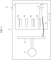
- Fig. 1 is a diagram illustrating the minimum structure of a device according to a first embodiment.
- the device 1 comprises at least a rack 2, an enclosure 3, a module 4, a main pipe 5, a branching tube 6, a cooling unit 7, a connection tube 8 and module connection portions 10.
- the enclosure 3 is provided inside the rack 2. Inside the enclosure 3 are provided a plurality of module connection portions 10 to which the module 4 is connected.
- the module 4 is provided inside the enclosure 3.
- a heat-generating component 9 is mounted on the module 4.
- the main pipe 5 is provided in the rack 2.
- the branching tube 6 is connected to the main pipe 5.
- the cooling unit 7 cools the heat-generating component 9 mounted on the module 4.
- the connection tube 8 connects the branching tube 6 with the cooling unit 7.
- the enclosure 3 is able to slide, for example, in the direction of the arrow in the drawing, in a state in which the module 4 is connected to a module connection portion 10 and the cooling unit 7 is connected to the branching tube 6 by the connection tube 8.
- a plurality of module connection portions 10 are provided, so it is possible to connect a plurality of modules 4 inside the enclosure 3. Additionally, the module connection portions 10 are provided inside the enclosure 3, so the modules 4 can be easily attached to and detached from the enclosure 3.
- the connection tube 8 is connected to a cooling unit 7 mounted on a module 4, so it is possible to attach and detach a module 4, a cooling unit 7 and a connection tube 8 as a unit with respect to the enclosure 3. As a result thereof, it is possible to easily perform work such as the replacement of a module 4 inside the enclosure 3.
- Fig. 2 is a perspective view illustrating the structure of a server device according to a second embodiment.
- Fig. 3 is a plan view illustrating the structure of the server device according to the second embodiment.
- the server device (device) 100 of the present embodiment mainly comprises a rack 110, servers 20 housed inside the rack 110, a supply tube (main pipe) 101 and a discharge tube (main pipe) 102.
- the rack 110 houses, in the interior thereof, a plurality of servers 20 arranged in the vertical direction Dv.
- the supply tube 101 and the discharge tube 102 are provided inside the rack 110.
- the supply tube 101 and the discharge tube 102 are provided, inside the rack 110, to the rear of the server 20 in the front-rear direction Df.
- the supply tube 101 and the discharge tube 102 each extend in the vertical direction Dv.
- the supply tube 101 supplies, for example, cooling water, as a cooling medium, to the server device 100.
- the discharge tube 102 discharges cooling water from the server device 100.
- Fig. 4 is a perspective view illustrating the structure of a server according to the second embodiment.
- Fig. 5 is a section view illustrating the structure of the server according to the second embodiment.
- the server 20 comprises an enclosure 21, module connectors (module connection portions) 23 and modules 30.
- the enclosure 21 is in the form of a rectangular parallelepiped-shaped hollow box.
- the enclosure 21 is supported so as to be able to slide inside the rack 110 in the front-rear direction (sliding direction) Df by means of a slide rail (not illustrated).
- the enclosure 21 comprises a bottom plate 21b, side plates 21s, a front plate 21f and a rear plate 21r.
- the bottom plate 21b is rectangular, extending in the front-rear direction Df and in the width direction Dw orthogonal to the front-rear direction Df.
- the side plates 21s are located on both sides, in the width direction Dw, of the bottom plate 21b.
- the side plates 21s respectively extend upward, in the vertical direction Dv, from both sides, in the width direction Dw, of the bottom plate 21b.
- the front plate 21f is positioned on one end, in the front-rear direction Df, of the bottom plate 21b.
- the front plate 21 f extends upward from the front end of the bottom plate 21b.
- the rear plate 21r is located on the other end, in the front-rear direction Df, of the bottom plate 21b.
- the rear plate 21r extends upward from the rear end of the bottom plate 21b.
- the rear plate 21r has openings 25 penetrating therethrough in the front-rear direction Df.
- a plurality of openings 25 are provided so as to be spaced in the width direction Dw.
- the base substrate 26 is plate-shaped, and is provided along the bottom plate 21b of the enclosure 21.
- Module connectors 23 are provided on the upper surface of the base substrate 26. A plurality of module connectors 23 are provided so as to be spaced in the width direction Dw.
- a module 30 comprises a substrate 32, a cooling unit 33, a supply connection tube (connection tube) 36 and a discharge connection tube (connection tube) 37.
- the substrate 32 is in the form of a rectangular plate. In the state in which the module 30 is housed in the enclosure 21, the substrate 32 is arranged so that a long edge S11 is aligned with the front-rear direction Df and the short edge S12 is aligned with the vertical direction Dv. The substrate 32 is connected, so as to be able to be inserted and removed, to a module connector 23 provided on the base substrate 26.
- the substrate 32 has a heat-generating component 34 such as a CPU (Central Processing Unit).
- the heat-generating component 34 is mounted on one surface 32f of the substrate 32.
- the heat-generating component 34 is not limited to being a CPU, and may be another electronic component.
- the cooling unit 33 is provided on the substrate 32.
- the cooling unit 33 is provided so as to be stacked on the heat-generating component 34.
- the cooling unit 33 cools the heat-generating component 34.
- the cooling unit 33 has a prescribed thickness in the direction orthogonal to the one surface 32f of the substrate 32.
- the cooling unit 33 has a recess 33s on the surface facing the heat-generating component 34. The recess 33s faces at least part of the surface of the heat-generating component 34.
- the supply connection tube 36 has one end 36a connected to the cooling unit 33.
- the supply connection tube 36 extends outside the substrate 32.
- the supply connection tube 36 extends from the substrate 32 through an opening 25 formed in the rear plate 21r of the enclosure 21, and to the rear of the enclosure 21.
- the supply connection tube 36 has flexibility.
- the supply connection tube 36 has a connection elbow 36c on the other end extending to the rear of the enclosure 21.
- the discharge connection tube 37 has one end 37a connected to the cooling unit 33.
- the discharge connection tube 37 extends to the outside of the substrate 32.
- the discharge connection tube 37 extends from the substrate 32 through an opening 25 formed in the rear plate 21r of the enclosure 21, and to the rear of the enclosure 21.
- the discharge connection tube 37 has flexibility.
- the discharge connection tube 37 has a connection elbow 37c on the other end extending to the rear of the enclosure 21.
- Such a module 30 is connected to each of the plurality of module connectors 23 provided in the width direction (first direction) Dw inside the enclosure 21. As a result thereof, a plurality of modules 30 arranged along the width direction Dw are provided inside the enclosure 21.
- supply branching tubes 41 and discharge branching tubes (branching tubes) 42 are provided inside the rack 110.
- a supply branching tube 41 and a discharge branching tube 42 are provided outside the enclosure 21 of each server 20.
- the supply branching tube 41 and the discharge branching tube 42 are provided to the rear, in the front-rear direction Df, of each server 20.
- the supply branching tube 41 and the discharge branching tube 42 are provided on one side (to the rear) in the sliding direction (front-rear direction Df) of the enclosure 21.
- the supply branching tube 41 and the discharge branching tube 42 are each supported on the enclosure 21 by a supporting member, which is not illustrated.
- the supply branching tube 41 and the discharge branching tube 42 each extend in the width direction Dw of the enclosure 21.
- connection elbows 36c of supply connection tubes 36 are connected to the supply branching tube 41.
- the connection elbows 36c of the supply connection tubes 36 are detachably connected to the supply branching tube 41.
- the supply branching tube 41 and the cooling units 33 of the modules 30 are respectively connected by supply connection tubes 36.
- connection elbows 37c of discharge connection tubes 37 are provided along the axial direction (width direction Dw) of the discharge branching tube 42.
- the connection elbows 37c of the discharge connection tubes 37 are detachably connected to the discharge branching tube 42.
- the discharge branching tube 42 and the cooling units 33 of the modules 30 are respectively connected by discharge connection tubes 37.
- the supply branching tube 41 and the discharge branching tube 42 are provided so as to leave a gap therebetween. Specifically, the supply branching tube 41 and the discharge branching tube 42 are provided so as to leave a gap in the vertical direction Dv. In other words, the supply branching tube 41 and the discharge branching tube 42 are located at different positions in the vertical direction Dv. The supply branching tube 41 and the discharge branching tube 42 are provided at positions facing the rear plate 21r of the enclosure 21 in the front-rear direction Df.
- a plurality of supply branching tubes 41 and discharge branching tubes 42 are provided so as to be respectively connected to the plurality of enclosures 21.
- the supply branching tubes 41 and the discharge branching tubes 42 are supported on the enclosures 21 by means of support members (not illustrated), and thus can slide, together with the enclosures 21, in the front-rear direction Df inside the rack 110.
- modules 30 when the enclosure 21 of each server 20 is made to slide in the front-rear direction Df inside the rack 110, the modules 30, the supply branching tube 41 and the discharge branching tube 42 slide together with the enclosure 21.
- modules 30 connected to the module connectors 23 are housed inside the enclosure 21, and the cooling units 33 are in a state of connection to the supply branching tube 41 and the discharge branching tube 42, by means of supply connection tubes 36 and discharge connection tubes 37, respectively.
- the supply branching tubes 41 are connected to the supply tube 101.
- the supply branching tubes 41 are detachably connected to the supply tube 101.
- the supply tube 101 and the supply branching tubes 41 are connected by means of intermediate connection tubes (second connection tubes) 51 having flexibility.
- the intermediate connection tubes 51 are detachably connected to the supply tube 101.
- the supply branching tubes 42 are connected to the supply tube 102.
- the supply branching tubes 42 are detachably connected to the discharge tube 102.
- the discharge tube 102 and the discharge branching tubes 42 are connected by means of intermediate connection tubes (second connection tubes) 52 having flexibility.
- the intermediate connection tubes 52 are detachably connected to the discharge tube 102.
- the plurality of sets of supply branching tubes 41 and discharge branching tubes 42 provided respectively on the servers 20 are respectively detachably connected to a single supply tube 101 and a single discharge tube 102.
- Cooling water is fed, through the supply tube 101, to the supply discharge tube 41 of each server 20.
- cooling water is fed through the supply branching tubes 41 to the supply connection tubes 36.
- the supply connection tubes 36 supply cooling water to the recesses 33s in the cooling units 33.
- the discharge connection tubes 37 discharge cooling water from the recesses 33s in the cooling units 33.
- the cooling water that is discharged through the discharge connection tubes 37 is discharged from the discharge branching tubes 42 and the discharge tube 102 to the outside.
- This server device 100 comprises a rack 110, enclosures 21 provided inside the rack 110, and modules 30 provided inside the enclosures 21.
- This server device 100 comprises a supply tube 101, a discharge tube 102, supply branching tubes 41, discharge branching tubes 42, supply connection tubes 36 and discharge connection tubes 37.
- modules 30 are connected to a plurality of module connectors 23 provided inside the enclosures 21, and the enclosures 21 are able to slide in a state in which the cooling units 33 are connected to the supply branching tubes 41 and the discharge branching tubes 42 respectively by means of the supply connection tubes 36 and the discharge connection tubes 37.
- the enclosures 21 can be pulled out from the rack 110 and maintenance work and the like can be performed on the servers 20 without removing the supply branching tubes 41 and the discharge branching tubes 42 respectively from the supply connection tubes 36 and the discharge connection tubes 37.
- a plurality of module connectors 23 are provided, so a plurality of modules 30 can be connected inside an enclosure 21.
- the module connectors 23 are provided inside the enclosure 21, so the modules 30 can be easily attached to and detached from the enclosure 21. Therefore, work such as the replacement of modules 30 inside the enclosure 21 can be easily performed.
- the supply branching tubes 41 and the discharge branching tubes 42 are respectively detachably connected to the supply tube 101 and the discharge tube 102.
- the supply branching tubes 41 and the discharge branching tubes 42 are respectively removed from the supply tube 101 and the discharge tube 102.
- the supply branching tube 41 and the discharge branching tube 42 can be moved together with the enclosure 21.
- the modules 30 can be easily attached to and detached from the enclosure 21 that has been made to slide.
- the supply connection tubes 36 and the discharge connection tubes 37 are able to be respectively attached to and detached from the supply branching tubes 41 and the discharge branching tubes 42.
- the modules 30, the supply connection tubes 36 and the discharge connection tubes 37 can be removed from the enclosures 21 together. Therefore, the modules 30 (and the supply connection tubes 36 and the discharge connection tubes 37) can be easily replaced.
- supply connection tubes 36 and discharge connection tubes 37 having one end 36a, 37a connected to the modules 30 are arranged in the width direction Dw, which is the direction in which the modules 30 are arrayed.
- the connection elbows 36c, 37c on the other ends of the supply connection tubes 36 and the discharge connection tubes 37 can be easily connected, respectively, to the supply branching tubes 41 and the discharge branching tubes 42, which extend in the width direction Dw.
- the supply branching tubes 41 and the discharge branching tubes 42 are provided outside the enclosures 21.
- the work for attaching and detaching the supply connection tubes 36 and the discharge connection tubes 37 of the modules 30 with respect to the supply branching tubes 41 and the discharge branching tubes 42 can be performed outside the enclosures 21, thereby raising the work efficiency.
- the supply branching tubes 41 and the discharge branching tubes 42 are provided to the rear in the sliding direction of the enclosures 21.
- the work for attaching and detaching the supply connection tubes 36 and the discharge connection tubes 37 with respect to the supply branching tubes 41 and the discharge branching tubes 42 can be performed from the rear of the rack 110, thereby raising the work efficiency.
- a supply branching tube 41 and a discharge branching tube 42 are provided on each of a plurality of enclosures 21. Additionally, the plurality of supply branching tubes 41 and the discharge branching tubes 42 are detachably connected, respectively, to a single supply tube 101 and a single discharge tube 102. As a result thereof, a supply branching tube 41 and a discharge branching tube 42 are provided for each enclosure 21. Therefore, it is possible to arrange the supply connection tubes 36 and the discharge connection tubes 37 in an orderly manner between a plurality of servers 20.
- the supply tube 101 and the discharge tube 102 are respectively connected to the supply branching tubes 41 and the discharge branching tubes 42 by means of intermediate connection tubes 51, 52 having flexibility.
- the enclosures 21 can be made to slide forward and rearward to some degree with the supply tube 101 and the discharge tube 102 respectively still connected to the supply branching tubes 41 and the discharge branching tubes 42 by means of the intermediate connection tubes 51, 52. Additionally, the work of attaching and detaching the intermediate connection tubes 51, 52 to the supply tube 101 and the discharge tube 102, and to the supply branching tubes 41 and the discharge branching tubes 42, respectively, can be easily performed.
- the supply connection tubes 36 and the discharge connection tubes 37 can be respectively connected to the supply branching tubes 41 and the discharge branching tubes 42 provided outside the enclosures 21 through openings 25 formed in the enclosures 21.
- the supply connection tubes 36 and the discharge connection tubes 37 were arranged to be connected, respectively, to the supply branching tubes 41 and the discharge branching tubes 42 from the front in the front-rear direction Df.
- the supply connection tubes 36 and the discharge connection tubes 37 were respectively connected to sites located on the front sides, in the front-rear direction Df, of the supply branching tubes 41 and the discharge branching tubes 42.
- Fig. 6 is a perspective view illustrating the structure of a server according to a first modified example of the second embodiment.
- the supply connection tubes 36 and the discharge connection tubes 37 are respectively connected to the supply branching tube 41 and the discharge branching tube 42 at sites other than sites facing the enclosure 21.
- the supply connection tubes 36 and the discharge connection tubes 37 are respectively connected to the supply branching tube 41 and the discharge branching tube 42 at sites at locations different from sites facing the enclosure 21.
- the connection elbows 36c, 37c of the supply connection tubes 36 and the discharge connection tubes 37 are respectively connected to the supply branching tube 41 and the discharge branching tube 42 from the rear in the front-rear direction Df.
- the supply connection tubes 36 and the discharge connection tubes 37 are respectively connected at sites positioned on the rear sides, in the front-rear direction Df, of the supply branching tube 41 and the discharge branching tube 42.
- the work of attaching and detaching the supply connection tubes 36 and the discharge connection tubes 37, respectively, to the supply branching tube 41 and the discharge branching tube 42 can be performed from the rear of the supply branching tube 41 and the discharge branching tube 42. As a result thereof, the work efficiency is raised.
- Fig. 7 is a perspective view illustrating the structure of a server according to the second modified example of the second embodiment.
- a supply branching tube 41 and a discharge branching tube 42 are provided so as to leave a gap therebetween in the vertical direction Dv.
- the supply branching tube 41 and the discharge branching tube 42 are provided at positions facing the rear plate 21r of the enclosure 21 in the front-rear direction Df.
- the supply connection tubes 36 and the discharge connection tubes 37 extend to the rear of the supply branching tube 41 and the discharge branching tube 42 by passing in between the supply branching tube 41 and the discharge branching tube 42.
- the supply connection tubes 36 and the discharge connection tubes 37 respectively curve forward at the rear, in the front-rear direction Df, of the supply branching tube 41 and the discharge branching tube 42.
- the supply connection tubes 36 and the discharge connection tubes 37 are respectively connected to the supply branching tube 41 and the discharge branching tube 42 at sites other than sites facing the enclosure 21.
- the connection elbows 36c, 37c of the supply connection tubes 36 and the discharge connection tubes 37 are respectively connected from the rear, in the front-rear direction Df, of the supply branching tube 41 and the discharge branching tube 42.
- the supply branching tube 41 and the discharge branching tube 42 are provided with a gap therebetween.
- the supply connection tubes 36 an the discharge connection tubes 37 can be passed between the supply branching tube 41 and the discharge branching tube 42. Additionally, working space for attaching and detaching the supply connection tubes 36 and the discharge connection tubes 37, respectively, to the supply branching tube 41 and the discharge branching tube 42 can be secured.
- the supply branching tube 41 and the discharge branching tube 42 are provided so as to leave a gap therebetween in the vertical direction.
- the supply connection tubes 36 and the discharge connection tubes 37 are arranged to pass between the supply branching tube 41 and the discharge branching tube 42.
- the supply connection tubes 36 and the discharge connection tubes 37 can be kept from sagging down by passing the supply connection tubes 36 and the discharge connection tubes 37 between the supply branching tube 41 and the discharge branching tube 42.
- the supply branching tube 41 and the discharge branching tube 42 are respectively connected with the supply connection tubes 36 and the discharge connection tubes 37 on sides not facing the enclosure 21, in other words, on the rear sides in the front-rear direction Df.
- the connection work for connecting the supply connection tubes 36 and the discharge connection tubes 37, respectively, with the supply branching tube 41 and the discharge branching tube 42 can be easily performed from the rear of the supply branching tube 41 and the discharge branching tube 42.
- the intermediate connection tubes 51, 52 are respectively detachably connected to the supply tube 101 and the discharge tube 102, but the intermediate connection tubes 51, 52 may be provided with slack. As a result thereof, it is possible to slide the enclosures 21 in the front-rear direction Df while the supply branching tubes 41 and the discharge branching tubes 42 remain connected to the supply tube 101 and the discharge tube 102 by means of the intermediate connection tubes 51, 52.
- supply branching tubes 41 and the discharge branching tubes 42 were connected, respectively, to the supply tube 101 and the discharge tube 102 by means of flexible intermediate connection tubes 51, 52.
- the invention is not limited to such a structure.
- Fig. 8 is a perspective view illustrating the structure of a server device according to another modified example of the second embodiment.
- the ends of the supply branching tubes 41 and the discharge branching tubes 42 may be directly connected, respectively, to the supply tube 101 and the discharge tube 102, without the intermediate connection tubes 51, 52 therebetween.
- the positions of the supply tube 101 and the discharge tube 102 are not limited to those indicated in the above-mentioned embodiments.
- the supply tube 101 and the discharge tube 102 may, for example, be provided at a central area in the width direction Dw or the like. Additionally, the supply tube 101 and the discharge tube 102 may be extended in the width direction Dw rather than in the vertical direction Dv, or may be provided in an upper area or a lower area of the rack 110.
- a device comprising:
- the device according to supplementary note 1 or 2, wherein: on the first connection tube, one end of which is connected to the cooling unit, the other end is detachably connected to the branching tube.
- the branching tube is provided outside the enclosure.
- the device of the present invention it is possible to easily perform work such as the replacement of a module inside an enclosure.
Landscapes
- Engineering & Computer Science (AREA)
- Microelectronics & Electronic Packaging (AREA)
- Physics & Mathematics (AREA)
- Thermal Sciences (AREA)
- Theoretical Computer Science (AREA)
- General Engineering & Computer Science (AREA)
- Human Computer Interaction (AREA)
- General Physics & Mathematics (AREA)
- Aviation & Aerospace Engineering (AREA)
- Computer Hardware Design (AREA)
- Cooling Or The Like Of Electrical Apparatus (AREA)
Abstract
Description
- The present invention relates to a device.
-
Patent Document 1 discloses a rack system for storing a plurality of cases in a rack. In this rack system, a plurality of electronic components are provided inside each case. Each case is provided with a plurality of pipes that feed a coolant, in a concentrated manner, to heat-generating components among the plurality of electronic components. Additionally, the rack is provided with a flow inlet manifold and a discharge outlet manifold to which the pipes of a plurality of cases are connected. The flow inlet manifold and the discharge outlet manifold are connected to a cooling return passage or a cooling discharge line. - [Patent Document 1]
Japanese Unexamined Patent Application, First Publication No2011-518395 - In some cases, a module inside a case (enclosure) is made detachable for the purpose of maintenance. The structure in
Patent Document 1 is a structure for cooling multiple electronic components at once, so labor is involved in attaching and detaching the electronic components inside the case and the pipes connected to the electronic components. Therefore, it is difficult to replace electronic components (modules) or to perform maintenance and inspections inside a server. - The present invention provides a device in which work such as the replacement of a module inside an enclosure can be easily performed.
- The device according to the present invention includes a rack; an enclosure provided inside the rack; a module provided inside the enclosure; a main pipe provided in the rack; a branching tube connected to the main pipe; a cooling unit that cools a heat-generating component mounted on the module; a first connection tube that connects the branching tube with the cooling unit; and a plurality of module connection portions that are provided inside the enclosure and to which the module is connected; wherein the enclosure can slide in a state in which the module is connected to the module connection portion, and the cooling unit and the branching tube are connected by the first connection tube.
- According to the device in the present invention, it is possible to easily perform work such as the replacement of a module inside an enclosure.
-
-
Fig. 1 is a diagram illustrating the minimum structure of a device according to a first embodiment. -
Fig. 2 is a perspective view illustrating the structure of a server device according to a second embodiment. -
Fig. 3 is a plan view illustrating the structure of the server device according to the second embodiment. -
Fig. 4 is a perspective view illustrating the structure of a server according to the second embodiment. -
Fig. 5 is a section view illustrating the structure of the server according to the second embodiment. -
Fig. 6 is a perspective view illustrating the structure of a server according to a first modified example of the second embodiment. -
Fig. 7 is a perspective view illustrating the structure of a server according to a second modified example of the second embodiment. -
Fig. 8 is a perspective view illustrating the structure of a server device according to another modified example of the second embodiment. - Multiple embodiments of the present invention will be explained below with reference to the drawings. However, regarding the present embodiments, the portions that are identical to the aforementioned conventional examples will be referred to by using the same names, and their explanations will be omitted.
-
Fig. 1 is a diagram illustrating the minimum structure of a device according to a first embodiment. - As illustrated in this drawing, it is sufficient for the
device 1 to comprise at least arack 2, an enclosure 3, a module 4, amain pipe 5, abranching tube 6, acooling unit 7, a connection tube 8 andmodule connection portions 10. - The enclosure 3 is provided inside the
rack 2. Inside the enclosure 3 are provided a plurality ofmodule connection portions 10 to which the module 4 is connected. - The module 4 is provided inside the enclosure 3. A heat-
generating component 9 is mounted on the module 4. - The
main pipe 5 is provided in therack 2. The branchingtube 6 is connected to themain pipe 5. - The
cooling unit 7 cools the heat-generatingcomponent 9 mounted on the module 4. The connection tube 8 connects thebranching tube 6 with thecooling unit 7. - In this
device 1, the enclosure 3 is able to slide, for example, in the direction of the arrow in the drawing, in a state in which the module 4 is connected to amodule connection portion 10 and thecooling unit 7 is connected to thebranching tube 6 by the connection tube 8. - In this
device 1, a plurality ofmodule connection portions 10 are provided, so it is possible to connect a plurality of modules 4 inside the enclosure 3. Additionally, themodule connection portions 10 are provided inside the enclosure 3, so the modules 4 can be easily attached to and detached from the enclosure 3. The connection tube 8 is connected to acooling unit 7 mounted on a module 4, so it is possible to attach and detach a module 4, acooling unit 7 and a connection tube 8 as a unit with respect to the enclosure 3. As a result thereof, it is possible to easily perform work such as the replacement of a module 4 inside the enclosure 3. -
Fig. 2 is a perspective view illustrating the structure of a server device according to a second embodiment.Fig. 3 is a plan view illustrating the structure of the server device according to the second embodiment. - As illustrated in
Fig. 2 andFig. 3 , the server device (device) 100 of the present embodiment mainly comprises arack 110,servers 20 housed inside therack 110, a supply tube (main pipe) 101 and a discharge tube (main pipe) 102. - The
rack 110 houses, in the interior thereof, a plurality ofservers 20 arranged in the vertical direction Dv. - The
supply tube 101 and thedischarge tube 102 are provided inside therack 110. Thesupply tube 101 and thedischarge tube 102 are provided, inside therack 110, to the rear of theserver 20 in the front-rear direction Df. Thesupply tube 101 and thedischarge tube 102 each extend in the vertical direction Dv. Thesupply tube 101 supplies, for example, cooling water, as a cooling medium, to theserver device 100. Thedischarge tube 102 discharges cooling water from theserver device 100. -
Fig. 4 is a perspective view illustrating the structure of a server according to the second embodiment.Fig. 5 is a section view illustrating the structure of the server according to the second embodiment. - As illustrated in
Fig. 3 to 5 , theserver 20 comprises anenclosure 21, module connectors (module connection portions) 23 andmodules 30. - The
enclosure 21 is in the form of a rectangular parallelepiped-shaped hollow box. Theenclosure 21 is supported so as to be able to slide inside therack 110 in the front-rear direction (sliding direction) Df by means of a slide rail (not illustrated). Theenclosure 21 comprises abottom plate 21b,side plates 21s, afront plate 21f and arear plate 21r. - In plan view, the
bottom plate 21b is rectangular, extending in the front-rear direction Df and in the width direction Dw orthogonal to the front-rear direction Df. Theside plates 21s are located on both sides, in the width direction Dw, of thebottom plate 21b. Theside plates 21s respectively extend upward, in the vertical direction Dv, from both sides, in the width direction Dw, of thebottom plate 21b. Thefront plate 21f is positioned on one end, in the front-rear direction Df, of thebottom plate 21b. Thefront plate 21 f extends upward from the front end of thebottom plate 21b. Therear plate 21r is located on the other end, in the front-rear direction Df, of thebottom plate 21b. Therear plate 21r extends upward from the rear end of thebottom plate 21b. - As illustrated in
Fig. 5 , therear plate 21r hasopenings 25 penetrating therethrough in the front-rear direction Df. A plurality ofopenings 25 are provided so as to be spaced in the width direction Dw. - Inside the
enclosure 21, abase substrate 26 is provided. Thebase substrate 26 is plate-shaped, and is provided along thebottom plate 21b of theenclosure 21. -
Module connectors 23 are provided on the upper surface of thebase substrate 26. A plurality ofmodule connectors 23 are provided so as to be spaced in the width direction Dw. - As illustrated in
Fig. 3 to 5 , amodule 30 comprises asubstrate 32, a coolingunit 33, a supply connection tube (connection tube) 36 and a discharge connection tube (connection tube) 37. - The
substrate 32 is in the form of a rectangular plate. In the state in which themodule 30 is housed in theenclosure 21, thesubstrate 32 is arranged so that a long edge S11 is aligned with the front-rear direction Df and the short edge S12 is aligned with the vertical direction Dv. Thesubstrate 32 is connected, so as to be able to be inserted and removed, to amodule connector 23 provided on thebase substrate 26. - The
substrate 32 has a heat-generatingcomponent 34 such as a CPU (Central Processing Unit). The heat-generatingcomponent 34 is mounted on onesurface 32f of thesubstrate 32. The heat-generatingcomponent 34 is not limited to being a CPU, and may be another electronic component. - The cooling
unit 33 is provided on thesubstrate 32. The coolingunit 33 is provided so as to be stacked on the heat-generatingcomponent 34. The coolingunit 33 cools the heat-generatingcomponent 34. The coolingunit 33 has a prescribed thickness in the direction orthogonal to the onesurface 32f of thesubstrate 32. The coolingunit 33 has arecess 33s on the surface facing the heat-generatingcomponent 34. Therecess 33s faces at least part of the surface of the heat-generatingcomponent 34. - The
supply connection tube 36 has oneend 36a connected to thecooling unit 33. Thesupply connection tube 36 extends outside thesubstrate 32. Thesupply connection tube 36 extends from thesubstrate 32 through anopening 25 formed in therear plate 21r of theenclosure 21, and to the rear of theenclosure 21. Thesupply connection tube 36 has flexibility. Thesupply connection tube 36 has aconnection elbow 36c on the other end extending to the rear of theenclosure 21. - The
discharge connection tube 37 has oneend 37a connected to thecooling unit 33. Thedischarge connection tube 37 extends to the outside of thesubstrate 32. Thedischarge connection tube 37 extends from thesubstrate 32 through anopening 25 formed in therear plate 21r of theenclosure 21, and to the rear of theenclosure 21. Thedischarge connection tube 37 has flexibility. Thedischarge connection tube 37 has aconnection elbow 37c on the other end extending to the rear of theenclosure 21. - Such a
module 30 is connected to each of the plurality ofmodule connectors 23 provided in the width direction (first direction) Dw inside theenclosure 21. As a result thereof, a plurality ofmodules 30 arranged along the width direction Dw are provided inside theenclosure 21. - As illustrated in
Fig. 2 andFig. 4 , inside therack 110, supply branching tubes (branching tubes) 41 and discharge branching tubes (branching tubes) 42 are provided. Asupply branching tube 41 and adischarge branching tube 42 are provided outside theenclosure 21 of eachserver 20. Thesupply branching tube 41 and thedischarge branching tube 42 are provided to the rear, in the front-rear direction Df, of eachserver 20. In other words, thesupply branching tube 41 and thedischarge branching tube 42 are provided on one side (to the rear) in the sliding direction (front-rear direction Df) of theenclosure 21. Thesupply branching tube 41 and thedischarge branching tube 42 are each supported on theenclosure 21 by a supporting member, which is not illustrated. - The
supply branching tube 41 and thedischarge branching tube 42 each extend in the width direction Dw of theenclosure 21. - On the
supply branching tube 41, a plurality of connection portions, to whichconnection elbows 36c ofsupply connection tubes 36 are connected, are provided along the axial direction (width direction Dw) of thesupply branching tube 41. Theconnection elbows 36c of thesupply connection tubes 36 are detachably connected to thesupply branching tube 41. As a result thereof, thesupply branching tube 41 and the coolingunits 33 of themodules 30 are respectively connected bysupply connection tubes 36. - On the
discharge branching tube 42, a plurality of connection portions, to whichconnection elbows 37c ofdischarge connection tubes 37 are connected, are provided along the axial direction (width direction Dw) of thedischarge branching tube 42. Theconnection elbows 37c of thedischarge connection tubes 37 are detachably connected to thedischarge branching tube 42. As a result thereof, thedischarge branching tube 42 and the coolingunits 33 of themodules 30 are respectively connected bydischarge connection tubes 37. - The
supply branching tube 41 and thedischarge branching tube 42 are provided so as to leave a gap therebetween. Specifically, thesupply branching tube 41 and thedischarge branching tube 42 are provided so as to leave a gap in the vertical direction Dv. In other words, thesupply branching tube 41 and thedischarge branching tube 42 are located at different positions in the vertical direction Dv. Thesupply branching tube 41 and thedischarge branching tube 42 are provided at positions facing therear plate 21r of theenclosure 21 in the front-rear direction Df. - Thus, a plurality of
supply branching tubes 41 anddischarge branching tubes 42 are provided so as to be respectively connected to the plurality ofenclosures 21. Thesupply branching tubes 41 and thedischarge branching tubes 42, as mentioned above, are supported on theenclosures 21 by means of support members (not illustrated), and thus can slide, together with theenclosures 21, in the front-rear direction Df inside therack 110. - Therefore, when the
enclosure 21 of eachserver 20 is made to slide in the front-rear direction Df inside therack 110, themodules 30, thesupply branching tube 41 and thedischarge branching tube 42 slide together with theenclosure 21. In this case,modules 30 connected to themodule connectors 23 are housed inside theenclosure 21, and the coolingunits 33 are in a state of connection to thesupply branching tube 41 and thedischarge branching tube 42, by means ofsupply connection tubes 36 anddischarge connection tubes 37, respectively. - As illustrated in
Fig. 2 , thesupply branching tubes 41 are connected to thesupply tube 101. Thesupply branching tubes 41 are detachably connected to thesupply tube 101. Thesupply tube 101 and thesupply branching tubes 41 are connected by means of intermediate connection tubes (second connection tubes) 51 having flexibility. Theintermediate connection tubes 51 are detachably connected to thesupply tube 101. - The
supply branching tubes 42 are connected to thesupply tube 102. Thesupply branching tubes 42 are detachably connected to thedischarge tube 102. Thedischarge tube 102 and thedischarge branching tubes 42 are connected by means of intermediate connection tubes (second connection tubes) 52 having flexibility. Theintermediate connection tubes 52 are detachably connected to thedischarge tube 102. - Thus, the plurality of sets of
supply branching tubes 41 anddischarge branching tubes 42 provided respectively on theservers 20 are respectively detachably connected to asingle supply tube 101 and asingle discharge tube 102. - Cooling water is fed, through the
supply tube 101, to thesupply discharge tube 41 of eachserver 20. In eachserver 20, cooling water is fed through thesupply branching tubes 41 to thesupply connection tubes 36. Thesupply connection tubes 36 supply cooling water to therecesses 33s in the coolingunits 33. - The
discharge connection tubes 37 discharge cooling water from therecesses 33s in the coolingunits 33. The cooling water that is discharged through thedischarge connection tubes 37 is discharged from thedischarge branching tubes 42 and thedischarge tube 102 to the outside. - This
server device 100 comprises arack 110,enclosures 21 provided inside therack 110, andmodules 30 provided inside theenclosures 21. Thisserver device 100 comprises asupply tube 101, adischarge tube 102,supply branching tubes 41,discharge branching tubes 42,supply connection tubes 36 anddischarge connection tubes 37. Furthermore,modules 30 are connected to a plurality ofmodule connectors 23 provided inside theenclosures 21, and theenclosures 21 are able to slide in a state in which thecooling units 33 are connected to thesupply branching tubes 41 and thedischarge branching tubes 42 respectively by means of thesupply connection tubes 36 and thedischarge connection tubes 37. - As a result thereof, the
enclosures 21 can be pulled out from therack 110 and maintenance work and the like can be performed on theservers 20 without removing thesupply branching tubes 41 and thedischarge branching tubes 42 respectively from thesupply connection tubes 36 and thedischarge connection tubes 37. Additionally, a plurality ofmodule connectors 23 are provided, so a plurality ofmodules 30 can be connected inside anenclosure 21. Additionally, when anenclosure 21 is in a state of removal from therack 110, themodule connectors 23 are provided inside theenclosure 21, so themodules 30 can be easily attached to and detached from theenclosure 21. Therefore, work such as the replacement ofmodules 30 inside theenclosure 21 can be easily performed. - In this
server device 100, thesupply branching tubes 41 and thedischarge branching tubes 42 are respectively detachably connected to thesupply tube 101 and thedischarge tube 102. Thesupply branching tubes 41 and thedischarge branching tubes 42 are respectively removed from thesupply tube 101 and thedischarge tube 102. As a result thereof, when asupply branching tube 41, adischarge branching tube 42 and anenclosure 21 are made to slide, thesupply branching tube 41 and thedischarge branching tube 42 can be moved together with theenclosure 21. As a result thereof, themodules 30 can be easily attached to and detached from theenclosure 21 that has been made to slide. - In this
server device 100, in a configuration in which themodules 30 are able to be attached to and detached from themodule connectors 23, thesupply connection tubes 36 and thedischarge connection tubes 37 are able to be respectively attached to and detached from thesupply branching tubes 41 and thedischarge branching tubes 42. As a result thereof, themodules 30, thesupply connection tubes 36 and thedischarge connection tubes 37 can be removed from theenclosures 21 together. Therefore, the modules 30 (and thesupply connection tubes 36 and the discharge connection tubes 37) can be easily replaced. - In this
server device 100,supply connection tubes 36 anddischarge connection tubes 37 having oneend modules 30 are arranged in the width direction Dw, which is the direction in which themodules 30 are arrayed. As a result thereof, theconnection elbows supply connection tubes 36 and thedischarge connection tubes 37 can be easily connected, respectively, to thesupply branching tubes 41 and thedischarge branching tubes 42, which extend in the width direction Dw. - In this
server device 100, thesupply branching tubes 41 and thedischarge branching tubes 42 are provided outside theenclosures 21. As a result thereof, the work for attaching and detaching thesupply connection tubes 36 and thedischarge connection tubes 37 of themodules 30 with respect to thesupply branching tubes 41 and thedischarge branching tubes 42 can be performed outside theenclosures 21, thereby raising the work efficiency. - In this
server device 100, thesupply branching tubes 41 and thedischarge branching tubes 42 are provided to the rear in the sliding direction of theenclosures 21. As a result thereof, the work for attaching and detaching thesupply connection tubes 36 and thedischarge connection tubes 37 with respect to thesupply branching tubes 41 and thedischarge branching tubes 42 can be performed from the rear of therack 110, thereby raising the work efficiency. - In this
server device 100, asupply branching tube 41 and adischarge branching tube 42 are provided on each of a plurality ofenclosures 21. Additionally, the plurality ofsupply branching tubes 41 and thedischarge branching tubes 42 are detachably connected, respectively, to asingle supply tube 101 and asingle discharge tube 102. As a result thereof, asupply branching tube 41 and adischarge branching tube 42 are provided for eachenclosure 21. Therefore, it is possible to arrange thesupply connection tubes 36 and thedischarge connection tubes 37 in an orderly manner between a plurality ofservers 20. - In this
server device 100, thesupply tube 101 and thedischarge tube 102 are respectively connected to thesupply branching tubes 41 and thedischarge branching tubes 42 by means ofintermediate connection tubes - As a result thereof, the
enclosures 21 can be made to slide forward and rearward to some degree with thesupply tube 101 and thedischarge tube 102 respectively still connected to thesupply branching tubes 41 and thedischarge branching tubes 42 by means of theintermediate connection tubes intermediate connection tubes supply tube 101 and thedischarge tube 102, and to thesupply branching tubes 41 and thedischarge branching tubes 42, respectively, can be easily performed. - In such a
server device 100, thesupply connection tubes 36 and thedischarge connection tubes 37 can be respectively connected to thesupply branching tubes 41 and thedischarge branching tubes 42 provided outside theenclosures 21 throughopenings 25 formed in theenclosures 21. - In the above-mentioned second embodiment, the
supply connection tubes 36 and thedischarge connection tubes 37 were arranged to be connected, respectively, to thesupply branching tubes 41 and thedischarge branching tubes 42 from the front in the front-rear direction Df. For example, thesupply connection tubes 36 and thedischarge connection tubes 37 were respectively connected to sites located on the front sides, in the front-rear direction Df, of thesupply branching tubes 41 and thedischarge branching tubes 42. However, there is no limitation thereto. -
Fig. 6 is a perspective view illustrating the structure of a server according to a first modified example of the second embodiment. - As illustrated in
Fig. 6 , thesupply connection tubes 36 and thedischarge connection tubes 37 are respectively connected to thesupply branching tube 41 and thedischarge branching tube 42 at sites other than sites facing theenclosure 21. For example, thesupply connection tubes 36 and thedischarge connection tubes 37 are respectively connected to thesupply branching tube 41 and thedischarge branching tube 42 at sites at locations different from sites facing theenclosure 21. In the present modified example, theconnection elbows supply connection tubes 36 and thedischarge connection tubes 37 are respectively connected to thesupply branching tube 41 and thedischarge branching tube 42 from the rear in the front-rear direction Df. For example, thesupply connection tubes 36 and thedischarge connection tubes 37 are respectively connected at sites positioned on the rear sides, in the front-rear direction Df, of thesupply branching tube 41 and thedischarge branching tube 42. - In this
server device 100, the work of attaching and detaching thesupply connection tubes 36 and thedischarge connection tubes 37, respectively, to thesupply branching tube 41 and thedischarge branching tube 42 can be performed from the rear of thesupply branching tube 41 and thedischarge branching tube 42. As a result thereof, the work efficiency is raised. -
Fig. 7 is a perspective view illustrating the structure of a server according to the second modified example of the second embodiment. - As illustrated in
Fig. 7 , asupply branching tube 41 and adischarge branching tube 42 are provided so as to leave a gap therebetween in the vertical direction Dv. Thesupply branching tube 41 and thedischarge branching tube 42 are provided at positions facing therear plate 21r of theenclosure 21 in the front-rear direction Df. - The
supply connection tubes 36 and thedischarge connection tubes 37 extend to the rear of thesupply branching tube 41 and thedischarge branching tube 42 by passing in between thesupply branching tube 41 and thedischarge branching tube 42. Thesupply connection tubes 36 and thedischarge connection tubes 37 respectively curve forward at the rear, in the front-rear direction Df, of thesupply branching tube 41 and thedischarge branching tube 42. Thesupply connection tubes 36 and thedischarge connection tubes 37 are respectively connected to thesupply branching tube 41 and thedischarge branching tube 42 at sites other than sites facing theenclosure 21. In the present modified example, theconnection elbows supply connection tubes 36 and thedischarge connection tubes 37 are respectively connected from the rear, in the front-rear direction Df, of thesupply branching tube 41 and thedischarge branching tube 42. - In this
server device 100, thesupply branching tube 41 and thedischarge branching tube 42 are provided with a gap therebetween. As a result thereof, thesupply connection tubes 36 an thedischarge connection tubes 37 can be passed between thesupply branching tube 41 and thedischarge branching tube 42. Additionally, working space for attaching and detaching thesupply connection tubes 36 and thedischarge connection tubes 37, respectively, to thesupply branching tube 41 and thedischarge branching tube 42 can be secured. - In this
server device 100, thesupply branching tube 41 and thedischarge branching tube 42 are provided so as to leave a gap therebetween in the vertical direction. Thesupply connection tubes 36 and thedischarge connection tubes 37 are arranged to pass between thesupply branching tube 41 and thedischarge branching tube 42. Thus, thesupply connection tubes 36 and thedischarge connection tubes 37 can be kept from sagging down by passing thesupply connection tubes 36 and thedischarge connection tubes 37 between thesupply branching tube 41 and thedischarge branching tube 42. - In this
server device 100, thesupply branching tube 41 and thedischarge branching tube 42 are respectively connected with thesupply connection tubes 36 and thedischarge connection tubes 37 on sides not facing theenclosure 21, in other words, on the rear sides in the front-rear direction Df. As a result thereof, the connection work for connecting thesupply connection tubes 36 and thedischarge connection tubes 37, respectively, with thesupply branching tube 41 and thedischarge branching tube 42 can be easily performed from the rear of thesupply branching tube 41 and thedischarge branching tube 42. - In the above-mentioned second embodiment and the modified examples thereof, the
intermediate connection tubes supply tube 101 and thedischarge tube 102, but theintermediate connection tubes enclosures 21 in the front-rear direction Df while thesupply branching tubes 41 and thedischarge branching tubes 42 remain connected to thesupply tube 101 and thedischarge tube 102 by means of theintermediate connection tubes - Additionally, the
supply branching tubes 41 and thedischarge branching tubes 42 were connected, respectively, to thesupply tube 101 and thedischarge tube 102 by means of flexibleintermediate connection tubes -
Fig. 8 is a perspective view illustrating the structure of a server device according to another modified example of the second embodiment. - As illustrated in
Fig. 8 , the ends of thesupply branching tubes 41 and thedischarge branching tubes 42 may be directly connected, respectively, to thesupply tube 101 and thedischarge tube 102, without theintermediate connection tubes - Furthermore, the positions of the
supply tube 101 and thedischarge tube 102 are not limited to those indicated in the above-mentioned embodiments. Thesupply tube 101 and thedischarge tube 102 may, for example, be provided at a central area in the width direction Dw or the like. Additionally, thesupply tube 101 and thedischarge tube 102 may be extended in the width direction Dw rather than in the vertical direction Dv, or may be provided in an upper area or a lower area of therack 110. - Aside therefrom, it is possible to select whether or not to adopt features described in the above-mentioned embodiments, or to appropriately replace some of the features with other features, as long as the resulting device does not depart from the spirit of the present invention.
- Some or all of the above-mentioned embodiments may be described as in the following supplementary notes, but the present invention is not limited to the following.
- A device comprising:
- a rack;
- an enclosure provided inside the rack;
- a module provided inside the enclosure;
- a main pipe provided in the rack;
- a branching tube connected to the main pipe;
- a cooling unit that cools a heat-generating component mounted on the module;
- a first connection tube that connects the branching tube with the cooling unit; and
- a plurality of module connection portions that are provided inside the enclosure and to which the module is connected;
- wherein the enclosure can slide in a state in which the module is connected to the module connection portion, and the cooling unit and the branching tube are connected by the first connection tube.
- The device according to
supplementary note 1, wherein the branching tube is detachably connected to the main pipe. - The device according to
supplementary note
on the first connection tube, one end of which is connected to the cooling unit, the other end is detachably connected to the branching tube. - The device according to any one of
supplementary notes 1 to 3, wherein: - a plurality of the modules, which are connected to the module connection portions inside the enclosure, are arrayed in a first direction; and
- the branching tube is arranged so as to extend in the first direction.
- The device according to any one of
supplementary notes 1 to 4, wherein:
the branching tube is provided outside the enclosure. - The device according to
supplementary note 5, wherein the branching tube is provided on one side in a sliding direction of the enclosure. - The device according to any one of
supplementary notes 1 to 6, wherein: - a plurality of enclosures are housed inside the rack;
- a plurality of the branching tubes are connected, respectively, to the plurality of enclosures; and
- the plurality of branching tubes are detachably connected to the single main pipe.
- The device according to any one of
supplementary notes 1 to 7, wherein:
the main pipe and the branching tube are connected by a second connection tube having flexibility. - The device according to any one of
supplementary notes 1 to 8, wherein: - an opening is formed in the enclosure; and
- the first connection tube is arranged to pass through the opening.
- The device according to any one of
supplementary notes 1 to 9, wherein: - the branching tube has a supply branching tube that supplies a cooling medium to the module and a discharge branching tube that discharges the cooling medium; and
- the supply branching tube and the discharge branching tube are provided so as to leave a gap therebetween.
- The device according to
supplementary note 10, wherein: - the supply branching tube and the discharge branching tube are provided so as to leave a gap in a vertical direction; and
- the first connection tube is arranged to pass between the supply branching tube and the discharge branching tube.
- The device according to any one of
supplementary notes 1 to 11, wherein: - the branching tube is provided at a position facing the enclosure; and
- the first connection tube is connected to the branching tube at a site other than a site facing the enclosure.
- Priority is claimed on Japanese Patent Application No.
2017-201777, filed October 18, 2017 - According to the device of the present invention, it is possible to easily perform work such as the replacement of a module inside an enclosure.
-
- 1
- Device
- 2
- Rack
- 3
- Enclosure
- 4
- Module
- 5
- Main pipe
- 6
- Branching tube
- 7
- Cooling unit
- 8
- Connection tube
- 9
- Heat-generating component
- 10
- Module connection portion
- 20
- Server
- 21
- Enclosure
- 23
- Module connector (module connection portion)
- 25
- Opening
- 30
- Module
- 33
- Cooling unit
- 34
- Heat-generating component
- 36
- Supply connection tube (first connection tube)
- 36a
- One end
- 36c
- Connection elbow
- 37
- Discharge connection tube (first connection tube)
- 37a
- One end
- 37c
- Connection elbow
- 41
- Supply branching tube (branching tube)
- 42
- Discharge branching tube (branching tube)
- 51
- Intermediate connection tube (second connection tube)
- 52
- Intermediate connection tube (second connection tube)
- 100
- Server device (device)
- 101
- Supply tube (main pipe)
- 102
- Discharge tube (main pipe)
- 110
- Rack
- Df
- Front-rear direction (sliding direction)
- Dv
- Vertical direction
- Dw
- Width direction (first direction)
Claims (12)
- A device comprising:a rack;an enclosure provided inside the rack;a module provided inside the enclosure;a main pipe provided in the rack;a branching tube connected to the main pipe;a cooling unit that cools a heat-generating component mounted on the module;a first connection tube that connects the branching tube with the cooling unit; anda plurality of module connection portions that are provided inside the enclosure and to which the module is connected;wherein the enclosure can slide in a state in which the module is connected to the module connection portion, and the cooling unit and the branching tube are connected by the first connection tube.
- The device according to claim 1, wherein the branching tube is detachably connected to the main pipe.
- The device according to claim 1 or 2, wherein:
on the first connection tube, one end of which is connected to the cooling unit, the other end is detachably connected to the branching tube. - The device according to any one of claims 1 to 3, wherein:a plurality of the modules, which are connected to the module connection portions inside the enclosure, are arrayed in a first direction; andthe branching tube is arranged so as to extend in the first direction.
- The device according to any one of claims 1 to 4, wherein:
the branching tube is provided outside the enclosure. - The device according to claim 5, wherein the branching tube is provided on one side in a sliding direction of the enclosure.
- The device according to any one of claims 1 to 6, wherein:a plurality of enclosures are housed inside the rack;a plurality of the branching tubes are connected, respectively, to the plurality of enclosures; andthe plurality of branching tubes are detachably connected to the single main pipe.
- The device according to any one of claims 1 to 7, wherein:
the main pipe and the branching tube are connected by a second connection tube having flexibility. - The device according to any one of claims 1 to 8, wherein:an opening is formed in the enclosure; andthe first connection tube is arranged to pass through the opening.
- The device according to any one of claims 1 to 9, wherein:the branching tube has a supply branching tube that supplies a cooling medium to the module and a discharge branching tube that discharges the cooling medium; andthe supply branching tube and the discharge branching tube are provided so as to leave a gap therebetween.
- The device according to claim 10, wherein:the supply branching tube and the discharge branching tube are provided so as to leave a gap in a vertical direction; andthe first connection tube is arranged to pass between the supply branching tube and the discharge branching tube.
- The device according to any one of claims 1 to 11, wherein:the branching tube is provided at a position facing the enclosure; andthe first connection tube is connected to the branching tube at a site other than a site facing the enclosure.
Applications Claiming Priority (2)
| Application Number | Priority Date | Filing Date | Title |
|---|---|---|---|
| JP2017201777A JP7036416B2 (en) | 2017-10-18 | 2017-10-18 | Device |
| PCT/JP2018/028410 WO2019077838A1 (en) | 2017-10-18 | 2018-07-30 | Device |
Publications (2)
| Publication Number | Publication Date |
|---|---|
| EP3699730A1 true EP3699730A1 (en) | 2020-08-26 |
| EP3699730A4 EP3699730A4 (en) | 2021-07-14 |
Family
ID=66173659
Family Applications (1)
| Application Number | Title | Priority Date | Filing Date |
|---|---|---|---|
| EP18867643.1A Withdrawn EP3699730A4 (en) | 2017-10-18 | 2018-07-30 | DEVICE |
Country Status (4)
| Country | Link |
|---|---|
| US (1) | US11231756B2 (en) |
| EP (1) | EP3699730A4 (en) |
| JP (1) | JP7036416B2 (en) |
| WO (1) | WO2019077838A1 (en) |
Families Citing this family (7)
| Publication number | Priority date | Publication date | Assignee | Title |
|---|---|---|---|---|
| CN113093872B (en) * | 2020-01-08 | 2022-09-02 | 富联精密电子(天津)有限公司 | Server |
| US11582886B2 (en) * | 2020-02-05 | 2023-02-14 | Baidu Usa Llc | Modular server cooling system |
| US11497139B2 (en) * | 2020-05-27 | 2022-11-08 | Baidu Usa Llc | Complete blind-mate connection system for liquid cooling |
| US12127372B2 (en) * | 2020-09-23 | 2024-10-22 | Baidu Usa Llc | Electronic rack fluid distribution system |
| US11871547B2 (en) * | 2021-09-02 | 2024-01-09 | Baidu Usa Llc | Two phase system for enclosure systems |
| US11910575B2 (en) | 2021-09-02 | 2024-02-20 | Baidu Usa Llc | Rack systems and packaging for servers |
| US11906092B2 (en) | 2022-03-25 | 2024-02-20 | Quanta Computer Inc. | Quick-disconnect assembly for a fluid line in a server |
Family Cites Families (21)
| Publication number | Priority date | Publication date | Assignee | Title |
|---|---|---|---|---|
| US6981543B2 (en) * | 2001-09-20 | 2006-01-03 | Intel Corporation | Modular capillary pumped loop cooling system |
| US7133283B2 (en) * | 2002-01-04 | 2006-11-07 | Intel Corporation | Frame-level thermal interface component for transfer of heat from an electronic component of a computer system |
| JP4199018B2 (en) * | 2003-02-14 | 2008-12-17 | 株式会社日立製作所 | Rack mount server system |
| US7342789B2 (en) * | 2005-06-30 | 2008-03-11 | International Business Machines Corporation | Method and apparatus for cooling an equipment enclosure through closed-loop, liquid-assisted air cooling in combination with direct liquid cooling |
| JP2007066480A (en) | 2005-09-02 | 2007-03-15 | Hitachi Ltd | Disk array device |
| JP4859823B2 (en) | 2007-12-14 | 2012-01-25 | 株式会社日立製作所 | COOLING DEVICE AND ELECTRONIC DEVICE USING THE SAME |
| WO2009131810A2 (en) | 2008-04-21 | 2009-10-29 | Hardcore Computer, Inc. | A case and rack system for liquid submersion cooling of electronic devices connected in an array |
| US8035972B2 (en) * | 2009-07-31 | 2011-10-11 | Oracle America, Inc. | Method and apparatus for liquid cooling computer equipment |
| US8027162B2 (en) * | 2009-09-24 | 2011-09-27 | International Business Machines Corporation | Liquid-cooled electronics apparatus and methods of fabrication |
| US20110240281A1 (en) * | 2010-03-31 | 2011-10-06 | Industrial Idea Partners, Inc. | Liquid-Based Cooling System For Data Centers Having Proportional Flow Control Device |
| US8351206B2 (en) * | 2010-06-29 | 2013-01-08 | International Business Machines Corporation | Liquid-cooled electronics rack with immersion-cooled electronic subsystems and vertically-mounted, vapor-condensing unit |
| JP5836029B2 (en) | 2011-09-20 | 2015-12-24 | 株式会社日立製作所 | Server rack cooling system and server equipment |
| US8638559B2 (en) * | 2011-11-10 | 2014-01-28 | International Business Machines Corporation | User-serviceable liquid DIMM cooling system |
| US8587943B2 (en) * | 2011-11-28 | 2013-11-19 | International Business Machines Corporation | Liquid-cooling memory modules with liquid flow pipes between memory module sockets |
| JP5910339B2 (en) | 2012-06-13 | 2016-04-27 | 富士通株式会社 | Couplers, sockets and plugs |
| KR102137294B1 (en) * | 2012-09-25 | 2020-07-23 | 리퀴드쿨 솔루션즈, 인코포레이티드 | Method and aparatus to manage coolant pressure and flow for an array of liquid submerged electronic device |
| US9811127B2 (en) * | 2012-11-08 | 2017-11-07 | Hewlett Packard Enterprise Development Lp | Twin server blades for high-density clustered computer system |
| KR102288462B1 (en) * | 2013-11-22 | 2021-08-09 | 리퀴드쿨 솔루션즈, 인코포레이티드 | Scalable liquid submersion cooling system |
| WO2016076882A1 (en) | 2014-11-14 | 2016-05-19 | Hewlett Packard Enterprise Development Lp | Cooling rack |
| EP3220642B1 (en) | 2016-03-15 | 2018-03-07 | Axis AB | Method, apparatus and system for encoding a video stream by defining areas within a second image frame with image data common to a first image frame |
| JP6862777B2 (en) * | 2016-11-11 | 2021-04-21 | 富士通株式会社 | Manifold and information processing equipment |
-
2017
- 2017-10-18 JP JP2017201777A patent/JP7036416B2/en active Active
-
2018
- 2018-07-30 EP EP18867643.1A patent/EP3699730A4/en not_active Withdrawn
- 2018-07-30 US US16/756,047 patent/US11231756B2/en active Active
- 2018-07-30 WO PCT/JP2018/028410 patent/WO2019077838A1/en not_active Ceased
Also Published As
| Publication number | Publication date |
|---|---|
| JP7036416B2 (en) | 2022-03-15 |
| US11231756B2 (en) | 2022-01-25 |
| EP3699730A4 (en) | 2021-07-14 |
| WO2019077838A1 (en) | 2019-04-25 |
| JP2019074992A (en) | 2019-05-16 |
| US20200249732A1 (en) | 2020-08-06 |
Similar Documents
| Publication | Publication Date | Title |
|---|---|---|
| US11231756B2 (en) | Server rack cooling device | |
| US8737067B1 (en) | Connectivity scheme and cooling scheme for a large rack system | |
| US10257955B2 (en) | Cable backplane system having individually removable cable connector assemblies | |
| EP3302014B1 (en) | Server rack system and bidirectional power inlet | |
| US20070256957A1 (en) | Sub-rack with housing for receiving plug-in modules | |
| US9538684B2 (en) | Server device | |
| US20080180917A1 (en) | Cable management system and method of use thereof | |
| CN104488369B (en) | Electronic interconnection method and apparatus | |
| EP4061105A1 (en) | Electronic device | |
| WO2015037007A1 (en) | Phased array antenna assembly | |
| JP7156706B2 (en) | Cooling system, electronics | |
| JP5299357B2 (en) | Array antenna apparatus and module mounting shelf removal method | |
| EP3700313A1 (en) | Cooling system, module, and device | |
| US10750644B2 (en) | Rear side swappable fan array module design | |
| US12137538B2 (en) | Cooling system and electronic device | |
| US7410134B2 (en) | System and method for routing cables | |
| JP2015216262A (en) | Rack row power supply system | |
| US20150029676A1 (en) | Cable backplane system having a cable tray guide and support system | |
| JP7181516B2 (en) | Rack row feeding system | |
| US11963337B2 (en) | Contactless device and chip thermal management plate | |
| JP6237718B2 (en) | Cable holding structure, rack cabinet, and method | |
| JP7625348B2 (en) | Power Supply Cabinet | |
| CN210042507U (en) | Fixing device of industrial connector in data center and data center | |
| CN207783387U (en) | Fast-connecting type video module link | |
| US10555055B2 (en) | Patch panels for use with fiber optic and copper cables and support rack for the same |
Legal Events
| Date | Code | Title | Description |
|---|---|---|---|
| STAA | Information on the status of an ep patent application or granted ep patent |
Free format text: STATUS: THE INTERNATIONAL PUBLICATION HAS BEEN MADE |
|
| PUAI | Public reference made under article 153(3) epc to a published international application that has entered the european phase |
Free format text: ORIGINAL CODE: 0009012 |
|
| STAA | Information on the status of an ep patent application or granted ep patent |
Free format text: STATUS: REQUEST FOR EXAMINATION WAS MADE |
|
| 17P | Request for examination filed |
Effective date: 20200515 |
|
| AK | Designated contracting states |
Kind code of ref document: A1 Designated state(s): AL AT BE BG CH CY CZ DE DK EE ES FI FR GB GR HR HU IE IS IT LI LT LU LV MC MK MT NL NO PL PT RO RS SE SI SK SM TR |
|
| AX | Request for extension of the european patent |
Extension state: BA ME |
|
| DAV | Request for validation of the european patent (deleted) | ||
| DAX | Request for extension of the european patent (deleted) | ||
| A4 | Supplementary search report drawn up and despatched |
Effective date: 20210616 |
|
| RIC1 | Information provided on ipc code assigned before grant |
Ipc: G06F 1/20 20060101AFI20210610BHEP Ipc: H05K 7/18 20060101ALI20210610BHEP Ipc: H05K 7/20 20060101ALI20210610BHEP |
|
| STAA | Information on the status of an ep patent application or granted ep patent |
Free format text: STATUS: EXAMINATION IS IN PROGRESS |
|
| 17Q | First examination report despatched |
Effective date: 20230523 |
|
| GRAP | Despatch of communication of intention to grant a patent |
Free format text: ORIGINAL CODE: EPIDOSNIGR1 |
|
| STAA | Information on the status of an ep patent application or granted ep patent |
Free format text: STATUS: GRANT OF PATENT IS INTENDED |
|
| INTG | Intention to grant announced |
Effective date: 20250502 |
|
| STAA | Information on the status of an ep patent application or granted ep patent |
Free format text: STATUS: THE APPLICATION IS DEEMED TO BE WITHDRAWN |
|
| 18D | Application deemed to be withdrawn |
Effective date: 20250903 |