EP3699668A1 - Observation method, image processing device, and electron microscope - Google Patents
Observation method, image processing device, and electron microscope Download PDFInfo
- Publication number
- EP3699668A1 EP3699668A1 EP20156937.3A EP20156937A EP3699668A1 EP 3699668 A1 EP3699668 A1 EP 3699668A1 EP 20156937 A EP20156937 A EP 20156937A EP 3699668 A1 EP3699668 A1 EP 3699668A1
- Authority
- EP
- European Patent Office
- Prior art keywords
- image
- microscope image
- optical microscope
- metal particles
- electron microscope
- Prior art date
- Legal status (The legal status is an assumption and is not a legal conclusion. Google has not performed a legal analysis and makes no representation as to the accuracy of the status listed.)
- Granted
Links
Images




Classifications
-
- G—PHYSICS
- G01—MEASURING; TESTING
- G01N—INVESTIGATING OR ANALYSING MATERIALS BY DETERMINING THEIR CHEMICAL OR PHYSICAL PROPERTIES
- G01N1/00—Sampling; Preparing specimens for investigation
- G01N1/28—Preparing specimens for investigation including physical details of (bio-)chemical methods covered elsewhere, e.g. G01N33/50, C12Q
-
- G—PHYSICS
- G01—MEASURING; TESTING
- G01N—INVESTIGATING OR ANALYSING MATERIALS BY DETERMINING THEIR CHEMICAL OR PHYSICAL PROPERTIES
- G01N1/00—Sampling; Preparing specimens for investigation
- G01N1/28—Preparing specimens for investigation including physical details of (bio-)chemical methods covered elsewhere, e.g. G01N33/50, C12Q
- G01N1/30—Staining; Impregnating ; Fixation; Dehydration; Multistep processes for preparing samples of tissue, cell or nucleic acid material and the like for analysis
-
- G—PHYSICS
- G02—OPTICS
- G02B—OPTICAL ELEMENTS, SYSTEMS OR APPARATUS
- G02B21/00—Microscopes
- G02B21/06—Means for illuminating specimens
- G02B21/08—Condensers
- G02B21/10—Condensers affording dark-field illumination
-
- G—PHYSICS
- G02—OPTICS
- G02B—OPTICAL ELEMENTS, SYSTEMS OR APPARATUS
- G02B21/00—Microscopes
- G02B21/36—Microscopes arranged for photographic purposes or projection purposes or digital imaging or video purposes including associated control and data processing arrangements
- G02B21/365—Control or image processing arrangements for digital or video microscopes
-
- G—PHYSICS
- G06—COMPUTING OR CALCULATING; COUNTING
- G06V—IMAGE OR VIDEO RECOGNITION OR UNDERSTANDING
- G06V10/00—Arrangements for image or video recognition or understanding
- G06V10/20—Image preprocessing
- G06V10/24—Aligning, centring, orientation detection or correction of the image
- G06V10/245—Aligning, centring, orientation detection or correction of the image by locating a pattern; Special marks for positioning
-
- G—PHYSICS
- G06—COMPUTING OR CALCULATING; COUNTING
- G06V—IMAGE OR VIDEO RECOGNITION OR UNDERSTANDING
- G06V20/00—Scenes; Scene-specific elements
- G06V20/60—Type of objects
- G06V20/69—Microscopic objects, e.g. biological cells or cellular parts
- G06V20/693—Acquisition
-
- H—ELECTRICITY
- H01—ELECTRIC ELEMENTS
- H01J—ELECTRIC DISCHARGE TUBES OR DISCHARGE LAMPS
- H01J37/00—Discharge tubes with provision for introducing objects or material to be exposed to the discharge, e.g. for the purpose of examination or processing thereof
- H01J37/02—Details
- H01J37/22—Optical, image processing or photographic arrangements associated with the tube
-
- H—ELECTRICITY
- H01—ELECTRIC ELEMENTS
- H01J—ELECTRIC DISCHARGE TUBES OR DISCHARGE LAMPS
- H01J37/00—Discharge tubes with provision for introducing objects or material to be exposed to the discharge, e.g. for the purpose of examination or processing thereof
- H01J37/02—Details
- H01J37/22—Optical, image processing or photographic arrangements associated with the tube
- H01J37/226—Optical arrangements for illuminating the object; optical arrangements for collecting light from the object
-
- H—ELECTRICITY
- H01—ELECTRIC ELEMENTS
- H01J—ELECTRIC DISCHARGE TUBES OR DISCHARGE LAMPS
- H01J37/00—Discharge tubes with provision for introducing objects or material to be exposed to the discharge, e.g. for the purpose of examination or processing thereof
- H01J37/02—Details
- H01J37/244—Detectors; Associated components or circuits therefor
-
- H—ELECTRICITY
- H01—ELECTRIC ELEMENTS
- H01J—ELECTRIC DISCHARGE TUBES OR DISCHARGE LAMPS
- H01J37/00—Discharge tubes with provision for introducing objects or material to be exposed to the discharge, e.g. for the purpose of examination or processing thereof
- H01J37/26—Electron or ion microscopes; Electron or ion diffraction tubes
-
- B—PERFORMING OPERATIONS; TRANSPORTING
- B82—NANOTECHNOLOGY
- B82Y—SPECIFIC USES OR APPLICATIONS OF NANOSTRUCTURES; MEASUREMENT OR ANALYSIS OF NANOSTRUCTURES; MANUFACTURE OR TREATMENT OF NANOSTRUCTURES
- B82Y30/00—Nanotechnology for materials or surface science, e.g. nanocomposites
-
- H—ELECTRICITY
- H01—ELECTRIC ELEMENTS
- H01J—ELECTRIC DISCHARGE TUBES OR DISCHARGE LAMPS
- H01J2237/00—Discharge tubes exposing object to beam, e.g. for analysis treatment, etching, imaging
- H01J2237/20—Positioning, supporting, modifying or maintaining the physical state of objects being observed or treated
- H01J2237/202—Movement
- H01J2237/20292—Means for position and/or orientation registration
Definitions
- the present invention relates to an observation method, an image processing device, and an electron microscope.
- Localization of the target cell or the target protein can be observed in optical microscope observation by labelling a specific cell, a specific protein, or the like with a fluorescent protein or a fluorescent dye.
- a fluorescent protein green fluorescent protein (GFP) can be mentioned.
- fluorescent dyes fluorescein isothiocyanate (FITC), DAPI (4',6-diamidino-2-phenylindole), and the like can be mentioned.
- the fluorescent proteins or the fluorescent dyes are incompatible with preparation of specimens for an electron microscope.
- glutaraldehyde, or osmium tetroxide is used for fixing a specimen.
- the fluorescent protein or the fluorescent dye loses fluorescence due to crosslinking by glutaraldehyde, or oxidation by osmium tetroxide. For this reason, it is difficult to perform optical microscope observation of a specimen labelled with a fluorescent protein or a fluorescent dye after fixing the specimen.
- a certain known method includes observing a specimen labelled with a fluorescent protein undergoing a DAB (3,3'-diaminobenzidine) reaction with an optical microscope, then fixing the specimen, and observing the specimen with an electron microscope.
- fluorescent proteins ascorbic acid oxidase (APEX), mini singlet oxygen generator (miniSOG), and the like may be mentioned.
- the specimen after fixing of the specimen cannot be subjected to optical microscope observation.
- the specimen is fixed, followed by substitution of an organic solvent for the moisture in the cell (dehydration), substitution of a resin for the organic solvent (resin embedding), and polymerization of the resin.
- dehydration substitution of an organic solvent for the moisture in the cell
- resin embedding substitution of a resin for the organic solvent
- polymerization of the resin occurs.
- shrinkage of the specimen due to shrinkage of the resin occurs. This makes the alignment between the optical microscope image and the electron microscope image difficult.
- a quantum dot including a semiconductor material is known.
- transmission electron microscope observation a specimen must be sliced into thin pieces. Slicing of a specimen into thin pieces results in a decrease in amount of a fluorescent dye. For this reason, sufficient fluorescence signals cannot be obtained in optical microscope observation.
- an observation method including:
- an image processing device including:
- an electron microscope including the above image processing device.
- a particle diameter of a metal particle can be estimated from the color of a luminescent spot in an optical microscope image. Therefore, metal particles of an optical microscope image and metal particles of an electron microscope image can be readily associated with each other. Accordingly, it is possible to achieve alignment between an optical microscope image and an electron microscope image with precision.
- FIG. 1 is a flowchart illustrating one example of the observation method in accordance with the first embodiment.
- FIG. 2 is a diagram for illustrating a process of preparing a specimen in the observation method in accordance with the first embodiment.
- an observation target 2 is prepared.
- the observation target 2 is, for example, a biological specimen.
- the observation target 2 is fixed, followed by resin embedding.
- the observation target 2 embedded in resin is sliced into thin pieces by a microtome, or the like. A section of the observation target 2 is thus obtained.
- the process and the order of the pretreatments such as fixing, dyeing, and resin embedding with respect to the observation target 2 are not particularly restricted.
- the supporting film 4 is a very thin film of a polymer, carbon, or the like. Then, an aqueous solution including a plurality of metal particles 6 having different particle diameters is prepared. The resulting aqueous solution including the metal particles 6 is added dropwise on the supporting film 4, and is dried. The plurality of metal particles 6 can be thus placed on the supporting film 4.
- a specimen can be prepared by the above treatments.
- the metal particle 6 in which localized surface plasmon resonance is excited by irradiation with light is used as the mark for identifying the observation position.
- the particle diameter of the metal particle 6 is, for example, 20 nm or more and 1 ⁇ m or less.
- the shape of the metal particle 6 is, for example, a spherical shape.
- the oscillation of electrons due to localized surface plasmon resonance depends upon the particle diameter or the surface structure of the particle.
- a light with a specific wavelength is intensely absorbed or scattered by the oscillation of electrons due to localized surface plasmon resonance.
- the nano-size metal particle 6 can be observed in optical microscope observation.
- localized surface plasmon resonance changes the wavelength of the light to be absorbed depending upon the type, the particle diameter, the surface structure of the metal particle, and the like. For this reason, the particle diameter of the metal particle 6 can be estimated from the color of the scattered light from the metal particle 6 in optical microscope observation.
- metal particles 6 as the mark can provide absorption scattering contrast in electron microscope observation. Accordingly, a sufficient contrast can be obtained as the mark in the electron microscope image.
- gold particles are preferable. Gold particles are not corroded by an acid or an alkali except for aqua regia. Further, gold particles show low cytotoxicity, and is unlikely to exert an adverse effect even when placed in the cell. As the gold particles, Gold NanoUrchin may be used. Alternatively, as the metal particles 6, particles of an alloy of gold and silver may be used.
- the prepared specimen is observed by an optical microscope.
- optical microscope observation a dark-field image is observed. Namely, with optical microscope observation, a scattered light from the specimen is observed. With an optical microscope, the dark-field image is photographed by a camera capable of color photographing so that the color of the scattered light from the metal particles 6 can be checked. When the scattered light from the specimen can be checked, a bright-field image may be observed with the optical microscope observation.
- FIG. 3 schematically illustrates an optical microscope image I2 (dark-field image) of a specimen.
- the color of the scattered light from each metal particle 6 is expressed by hatching for convenience. Namely, the metal particles 6 with the same hatching indicate scattered light of the same color.
- an optical microscope image 12 a scattered light from each metal particle 6 is observed.
- a scattered light from the metal particles 6 as small as about 20 nm can be observed due to the effect of localized surface plasmon resonance.
- the scatted light from each metal particle 6 is observed as a luminescent spot.
- a luminescent spot is extracted from the optical microscope image 12.
- the metal particles 6 are extracted from the optical microscope image 12.
- the coordinates (X, Y) of each luminescent spot, and the information of the color of each luminescent spot are acquired from the optical microscope image 12.
- the coordinates (X, Y) of the luminescent spot and the information of the color of the luminescent spot can be said to be information on the coordinates of the metal particles and the color of the metal particles (the color of a scattered light from the metal particles) in the optical microscope image.
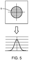
- FIGS. 4 and 5 are each a diagram for illustrating a process of determining the coordinates of the luminescent spot.
- FIG. 5 illustrates an enlarged view of a region V of FIG. 4 , and an intensity profile of the luminescent spot.
- the horizontal axis of the graph in FIG. 5 indicates the position of the optical microscope image, and the vertical axis indicates the brightness.
- the center of the luminescent spot in the optical microscope image I2 has the coordinates (X, Y) of the luminescent spot.
- the information of the coordinates (X, Y) of the luminescent spot is recorded as the coordinates (X, Y) of the metal particles; and the information of the color of the luminescent spot, as the information of the color of the metal particles.
- the coordinates (X, Y) of the metal particles and the information of the color of the metal particles are recorded in association with each other.
- the prepared specimen is observed with a transmission electron microscope.
- the observation by a transmission electron microscope may be performed in a dark field mode or may be performed in a bright field mode.
- FIG. 6 schematically illustrates a TEM image I4 (bright field image) of the specimen. As illustrated in FIG. 6 , an electron beam is absorbed and scattered by the metal particles 6. For this reason, in the TEM image 14, the metal particles 6 are observed as black dots.
- each metal particle 6 is extracted.
- the metal particles 6 are observed as black dots in the TEM image 14. For this reason, the coordinates of the centers of the black dots are assumed to be the coordinates (x, y) of the metal particles 6.
- FIG. 7 is a diagram for illustrating measurement of a particle diameter of the metal particles 6.
- a particle diameter of each metal particle 6 is measured.
- the information of a particle diameter of the metal particles 6 is recorded in association with the information of the coordinates (x, y) of the metal particles 6.
- information for associating the optical microscope image I2 and the TEM image I4 is determined.
- the information for associating the optical microscope image I2 and the TEM image I4 can be determined based on the information of each position and each color of a plurality of metal particles 6 acquired from the optical microscope image, and the information of each position and each particle diameter of a plurality of metal particles 6 acquired from the TEM image.
- the color of the metal particles 6 in the optical microscope image 12, namely, the color of a scattered light from the metal particles 6 depends upon the particle diameters of the metal particles 6. Specifically, with an increase in particle diameters of the metal particles 6, a light with a long wavelength is more absorbed by the metal particles 6 due to localized surface plasmon resonance. For this reason, from the information of the color (wavelength of the light) of the metal particles 6 acquired from the optical microscope image, the particle diameter of the metal particles 6 can be estimated. Using this, the particle diameter of the metal particles 6 and the position of the metal particles 6 are checked by comparison between two images. This can associate the metal particles 6 observed in the optical microscope image I2 and the metal particles 6 observed in the TEM image I4.
- FIGS. 8 and 9 are each a diagram for illustrating a process of determining the information for associating the optical microscope image I2 and the TEM image I4.
- the difference in magnification and the difference in direction between the optical microscope image I2 and the TEM image I4 can be determined.
- a vector V2 connecting two metal particles 6 is drawn in the optical microscope image 12.
- a vector V4 connecting two metal particles 6 is drawn in the TEM image 14.
- the difference in direction between the two images from the direction of the vector V2 and the direction of the vector V4.
- the difference in direction between the two images can be expressed as, for example, the angle formed by the vector V2 and the vector V4.
- the aberration of the optical system in an optical microscope and the aberration of the optical system in an electron microscope are different from each other. For this reason, for example, when the optical microscope image I2 is used as the standard, the TEM image I4 is distorted with respect to the optical microscope image I2. As described above, when three or more pairs of the corresponding metal particles 6 between the optical microscope image I2 and the TEM image I4 are found, it is possible to determine how the TEM image I4 is distorted with respect to the optical microscope image I2. Alternatively, how the optical microscope image I2 is distorted with respect to the TEM image I4 with reference to the TEM image I4 may be determined, for example.
- the magnifications of the optical microscope image I2 and the TEM image I4 are adjusted firs based on the information of the difference in magnification between the optical microscope image I2 and the TEM image I4. As a result, the magnifications of the optical microscope image I2 and the TEM image I4 are equalized. Further, based on the information of the difference in direction between the optical microscope image I2 and the TEM image I4, the directions of the optical microscope image I2 and the TEM image I4 are adjusted. For example, the direction can be adjusted by rotating the TEM image I4 with respect to the optical microscope image I2. As a result, the optical microscope image I2 and the TEM image I4 are aligned to the same direction. Further, based on the information of distortion between the two images, the distortion between the optical microscope image I2 and the TEM image I4 may be corrected.
- optical microscope image I2 adjusted in magnification, direction, and the like alignment between the optical microscope image I2 adjusted in magnification, direction, and the like, and the TEM image I4 adjusted in magnification, direction, and the like is performed, so that the optical microscope image I2 and the TEM image I4 are superimposed together, to form a single image.
- FIG. 10 schematically illustrates the image I6 generated by superimposing the optical microscope image I2 on the TEM image I4.
- the image I6 illustrated in FIG. 10 becomes an image utilizing the characteristics of both of the optical microscope image I2 and the TEM image I4.
- the specimen can be observed by combining the optical microscope and the transmission electron microscope.
- the optical microscope image and the TEM image are acquired.
- the image to be combined with the optical microscope image is an electron microscope image.
- the electron microscope images include a TEM image, a scanning electron microscope image (SEM image), and a scanning transmission electron microscope image (STEM image).
- SEM image scanning electron microscope image
- STEM image scanning transmission electron microscope image
- the particle diameter of the metal particles 6 can be measured as with the TEM image. For this reason, even when a microscope image and a SEM image are acquired, and when an optical microscope image and a STEM image are acquired, a specimen can be observed by the same treatment as that for acquiring an optical microscope image and a TEM image.
- observation target is a biological specimen.
- observation with a combination of an optical microscope and an electron microscope is possible.
- the observation method in accordance with the first embodiment has, for example, the following features.
- the observation method in accordance with the first embodiment includes the steps of: preparing a specimen including, as a mark, a plurality of metal particles in which localized surface plasmon resonance is excited by irradiation with light; acquiring information of positions and colors of the plurality of metal particles in an optical microscope image; acquiring information of positions and particle diameters of the plurality of metal particles in an electron microscope image; and determining information for associating the optical microscope image and the electron microscope image based on the information of the positions and the colors of the plurality of metal particles acquired from the optical microscope image, and the information of the positions and the particle diameters of the plurality of metal particles acquired from the electron microscope image.
- a plurality of metal particles 6 in which localized surface plasmon resonance is excited by irradiation with light are used as a mark.
- the plurality of metal particles 6 function as a mark for both of the optical microscope image and the electron microscope image without being affected by preparation of a specimen for an electron microscope. Therefore, in the observation method in accordance with the first embodiment, a specimen in the same state can be observed with an optical microscope and an electron microscope.
- the particle diameter of the metal particles can be estimated from the color of the luminescent spot in the optical microscope image. Therefore, the metal particles of the optical microscope image and the metal particles of the electron microscope image can be readily associated with each other. Accordingly, it is possible to achieve alignment between the optical microscope image and the electron microscope image with precision.
- the optical microscope image is, for example, a dark-field image.
- a dark-field image the color of a scattered light from the metal particles 6 is easy to see. For this reason, it is possible to estimate the particle diameter of the metal particles 6 from the optical microscope image with precision.
- FIG. 11 is a diagram illustrating a configuration of an electron microscope 100.
- the electron microscope 100 includes an image processing device 10 in accordance with the second embodiment.
- the electron microscope 100 includes the image processing device 10 and an electron microscope main body 20.
- the electron microscope main body 20 has, for example, a function as a transmission electron microscope.
- the electron microscope main body 20 includes an electron gun, an irradiation system for irradiating a specimen with an electron beam, a specimen stage for holding a specimen, an imaging system for imaging an image by electrons transmitted through the specimen, and a photographing device for photographing an image.
- the electron microscope main body 20 With the electron microscope main body 20, the electron beams emitted from the electron gun are converged by the irradiation system, and are applied to the specimen.
- the electron beam applied to the specimen is transmitted through the specimen.
- the imaging system a TEM image is imaged by the electrons transmitted through the specimen, and the TEM image is photographed by the photographing device.
- the image data of the TEM image photographed by the photographing device is sent to the image processing device 10, and is stored at a storage unit 124.
- the image processing device 10 includes an operation unit 120, a display unit 122, the storage unit 124, and a processing unit 110.
- the operation unit 120 performs processing of acquiring an operation signal in response to the operation by a user, and sending the operation signal to the processing unit 110.
- the function of the operation unit 120 can be achieved by, for example, a button, a key, a touch panel type display, or a microphone.
- the display unit 122 is for displaying the image generated by the processing unit 110.
- the function of the display unit 122 can be achieved by, for example, a display such as a liquid crystal display (LCD).
- LCD liquid crystal display
- the storage unit 124 stores a program, data, and the like for the processing unit 110 to perform a variety of calculation processing and control processing. Further, the storage unit 124 is used as the work area of the processing unit 110, and is also used for temporarily storing the results of calculation executed by the processing unit 110 in accordance with various programs, and the like.
- the function of the storage unit 124 can be implemented by, for example, a random access memory (RAM), a read only memory (ROM), and a hard disk.
- the processing unit 110 performs various control processing and calculation processing in accordance with the program stored in the storage unit 124.
- the function of the processing unit 110 can be implemented by executing a program by various processors (central processing unit (CPU), and the like).
- the processing unit 110 includes an image acquisition unit 112, a first image information acquisition unit 114, a second image information acquisition unit 116, a computation unit 118, and an image forming unit 119.
- the image acquisition unit 112 acquires an optical microscope image of a specimen including, as a mark, a plurality of metal particles in which localized surface plasmon resonance is excited by irradiation with light, and the electron microscope image of the specimen. For example, a user photographs the specimen using an optical microscope, and the resulting optical microscope image I2 (see FIG. 3 ) is stored in the storage unit 124.
- the image acquisition unit 112 reads the optical microscope image I2 stored in the storage unit 124, and acquires the optical microscope image I2. Further, the image acquisition unit 112 reads, for example, the TEM image I4 (see FIG. 6 ) photographed by the electron microscope main body 20, and stored in the storage unit 124, and acquires the TEM image 14.
- the first image information acquisition unit 114 acquires the information of the positions and the colors of a plurality of metal particles in the optical microscope image 12.
- the first image information acquisition unit 114 extracts a luminescent spot in the optical microscope image 12, and acquires the information of the coordinates of the luminescent spot and the color of the luminescent spot. As a result, the information of the position and the color of each metal particle can be acquired.
- the information of the position and the color of each metal particle is recorded in the storage unit 124.
- the second image information acquisition unit 116 acquires the information of the position and the particle diameter of each of the plurality of metal particles in the TEM image 14.
- the second image information acquisition unit 116 extracts the portion of the contrast corresponding to the metal particles 6 from the TEM image I4. For example, when the TEM image I4 is a bright field image, the metal particles 6 are observed as a black dot. For this reason, the second image information acquisition unit 116 acquires the information of the coordinates of the black dot and the particle diameter of the black dot. As a result, the information of the position and the particle diameter of each metal particle can be acquired.
- the information of the position and the particle diameter of each metal particle is recorded in the storage unit 124.
- the computation unit 118 determines the information for associating the optical microscope image I2 and the TEM image I4 based on the information of the positions and the colors of the plurality of metal particles 6 acquired from the optical microscope image 12, and the information of the positions and the particle diameters of the plurality of metal particles acquired from the TEM image I4.
- the information for associating the optical microscope image I2 and the TEM image I4 includes the information of the positions of the corresponding metal particles 6 between the two images, the information of the difference in magnification between the two images, and the information of the difference in direction between the two images. Further, information for associating the optical microscope image I2 and the TEM image I4 may include the information of the distortion between the two images.
- the computation unit 118 determines the information of the positions of the corresponding metal particles 6 between the optical microscope image I2 and the TEM image I4. Specifically, the computation unit 118 estimates the particle diameter of the metal particles 6 from the information of the color of the metal particles 6 in the optical microscope image 12. The computation unit 118 estimates the particle diameter of the metal particles 6 from the color of the metal particles 6 using the table showing the relationship between the particle diameter of the metal particles 6 and the color of a scattered light from the metal particles. The computation unit 118 checks the information of the estimated particle diameter and position of the metal particles 6 against the information of the particle diameter and the position of the metal particles 6 in the TEM image 14, and founds the corresponding metal particles 6 between the two images.
- the computation unit 118 determines the difference in magnification between two images from the difference in length between the vector V2 connecting two metal particles 6 in the optical microscope image I2 and the vector V4 connecting two metal particles 6 in the TEM image I4, for example, as illustrated in FIG. 8 . Further, the computation unit 118 determines the difference in direction between two images from the direction of the vector V2 and the direction of the vector V4.
- the computation unit 118 determines the distortion of the TEM image I4 with respect to the optical microscope image I2 when there are three or more pairs of corresponding metal particles 6 between two images.
- the distortion of the optical microscope image I2 with respect to the TEM image I4 may be determined.
- the image forming unit 119 performs alignment between the optical microscope image I2 and the TEM image I4 based on the information for associating the optical microscope image I2 and the TEM image I4, and forms a single image obtained by superimposing the optical microscope image I2 on the TEM image I4.
- the image forming unit 119 equalizes the magnifications of the optical microscope image I2 and the TEM image I4 based on the information of the difference in magnification between the optical microscope image I2 and the TEM image I4. Further, the image forming unit 119 equalizes the directions of the optical microscope image I2 and the TEM image I4 based on the information of the difference in direction between the optical microscope image I2 and the TEM image I4. Still further, when the information of the distortion of the TEM image I4 with respect to the optical microscope image I2 is obtained, the distortion between the optical microscope image I2 and the TEM image I4 is corrected.
- the image forming unit 119 performs alignment between the optical microscope image I2 and the TEM image I4 thus equalized in magnification and direction, and superimposes the optical microscope image I2 on the TEM image I4 to form a single image I6 (see FIG. 10 ).
- the image forming unit 119 allows the formed image I6 to be displayed on the display unit 122.
- the image processing device 10 has, for example, the following features.
- the computation unit 118 determines the information for associating the optical microscope image and the electron microscope image based on the information of the positions and the colors of a plurality of metal particles acquired from the optical microscope image, and the information of the positions and the particle diameters of a plurality of metal particles acquired from the electron microscope image.
- the image processing device 10 a plurality of metal particles 6 in which localized surface plasmon resonance is excited by irradiation with light are used as a mark.
- the particle diameter of the metal particles can be estimated with the color of the luminescent spot. Therefore, with the image processing device 10, the metal particles of the optical microscope image and the metal particles of the electron microscope image can be readily associated with each other. Accordingly, it is possible to perform alignment between the optical microscope image and the electron microscope image with precision.
- the image forming unit 119 performs alignment between the optical microscope image and the electron microscope image based on the information for associating the optical microscope image and the electron microscope image, and forms a single image obtained by superimposing the optical microscope image on the electron microscope image. For this reason, with the image processing device 10, it is possible to obtain an image utilizing the characteristics of both of the optical microscope image I2 and the TEM image I4.
- the aqueous solution including the metal particles 6 was added dropwise to the section of the observation target 2 on the supporting film 4, and was dried. As a result, the metal particles 6 were placed on the supporting film 4.
- the process of preparing a specimen including a plurality of metal particles 6 is not limited thereto.
- gold nanoparticles can be used as a mark of a cell, an intracellular minute organ, a protein to be observed.
- the gold nanoparticles are gold nanoparticles having a particle diameter of nano order.
- the surface of the gold nanoparticles can be variously decorated, and the gold nanoparticles can be bound with a protein or a substrate.
- gold nanoparticles are added to a culture medium, so that the gold nanoparticles are captured in the cell by endocytosis.
- gold nanoparticles can be injected into a cell.
- a protein when labelled with gold nanoparticles, an antibody against a protein to be observed is prepared, thereby performing immunostaining. At this step, gold nanoparticles are bound with a secondary antibody.
- labelling can also be achieved by binding gold nanoparticles to the substrate for the enzyme.
- an organism such as paramecium may be allowed to eat metal particles.
- a description will be given to a process of preparing a specimen when the observation target is a paramecium.
- gold nanoparticles are added to the culture medium cultivating a paramecium therein.
- the paramecium can be allowed to eat gold nanoparticles.
- the eaten gold nanoparticles are accumulated in the food vacuole of the paramecium.
- a specimen for a transmission electron microscope of the paramecium which has eaten the gold nanoparticles will be prepared.
- a paramecium is fixed with glutaraldehyde and osmium tetroxide, and is dehydrated by ethanol series, followed by embedding in an epoxy resin.
- the paramecium embedded in resin is sliced to a thickness of 100 nm or lower by a microtome.
- the resulting section is placed on a supporting film.
- the specimen section is double dyed with uranium acetate and lead citrate.
- FIG. 12 illustrates optical microscope images (dark-field images) and TEM images of a paramecium.
- the image (a) illustrated in FIG. 12 is an optical microscope image (dark-field image), and the image (b) is a TEM image of the same visual field as that of (a).
- an image (c) is an enlarged image of the image (a)
- an image (d) is an enlarged image of the image (b).
- An image (e) is an image obtained by superimposing the image (c) on the image (d).
- the gold nanoparticles as a mark were exposed to glutaraldehyde, osmium tetroxide, uranium oxide, or lead citrate during preparation of a specimen.
- the optical microscope image illustrated in FIG. 12 orange scattered light from the gold nanoparticles are observed mixed with a scattered light from the paramecium.
- the region shining in orange in the image (c) is the food vacuole of the paramecium. For this reason, in the image (d), the food vacuole of the paramecium can be identified.
- the label using gold particles is used in the immune electron microscopy.
- the immune electron microscopy is a process of visualizing the localization of the components forming a cell or a tissue using an immune reaction at the electron microscope level.
- the gold particles for use in the immune electron microscopy has a particle diameter of 5 nm or less so as to be penetrated into a cell or a tissue.
- the scattered light is weak, so that in optical microscope observation, the scattered light cannot be observed.
- the particle diameter of the gold nanoparticles may be increased.
- the cultured cell is fixed. Then, an anti-mitochondria antibody is allowed to react therewith as a primary antibody. Next, as a secondary antibody, a gold colloid labelled anti-Rabbit IgG antibody was allowed to react with the cultured cell.
- the gold colloid labelled anti-Rabbit IgG antibody includes gold nanoparticles bound to an anti-Rabbit IgG antibody. The particle diameter of the gold nanoparticles is 5 nm or less.
- a primary antibody and a secondary antibody are allowed to react with the cultured cell. Then, the particle diameter of the gold nanoparticles is increased by the gold sensitization. Next, the cultured cell is dehydrated, and embedded in resin, and the resin embedded cell is sliced into thin sections by an ultramicrotome, or the like. The specimen section thus prepared is placed on a supporting film.
- the particle diameter of the gold nanoparticles is increased by the gold sensitization as described above, a variation in particle diameter among the gold nanoparticles is caused. For this reason, in the optical microscope image, a plurality of luminescent spots having different colors are observed, and in the electron microscope image, a plurality of metal particles having different particle diameters are observed. Therefore, the metal particles of the optical microscope image and the metal particles of the electron microscope image can be readily associated with each other. Accordingly, it is possible to perform alignment between the optical microscope image and the electron microscope image with precision.
- the particle diameter of the metal particles is increased.
- the visibility in optical microscope observation can be enhanced while keeping the penetration into the cell or the tissue.
- the invention includes configurations that are substantially the same (for example, in function and method) as the configurations described in the embodiments.
- the invention also includes configurations in which non-essential elements described in the embodiments are replaced by other elements.
- the invention further includes configurations obtained by adding known art to the configurations described in the embodiments.
Landscapes
- Engineering & Computer Science (AREA)
- Physics & Mathematics (AREA)
- Analytical Chemistry (AREA)
- Chemical & Material Sciences (AREA)
- General Physics & Mathematics (AREA)
- Multimedia (AREA)
- Health & Medical Sciences (AREA)
- Life Sciences & Earth Sciences (AREA)
- General Health & Medical Sciences (AREA)
- Theoretical Computer Science (AREA)
- Optics & Photonics (AREA)
- Biochemistry (AREA)
- Molecular Biology (AREA)
- Biomedical Technology (AREA)
- Pathology (AREA)
- Immunology (AREA)
- Computer Vision & Pattern Recognition (AREA)
- Investigating, Analyzing Materials By Fluorescence Or Luminescence (AREA)
- Analysing Materials By The Use Of Radiation (AREA)
- Sampling And Sample Adjustment (AREA)
- Investigating Or Analysing Materials By Optical Means (AREA)
- Microscoopes, Condenser (AREA)
Abstract
Description
- The present invention relates to an observation method, an image processing device, and an electron microscope.
- A method which enables observation of the same part between an optical microscope and an electron microscope has been known (see, e.g.,
JP-A-8-162059 - Localization of the target cell or the target protein can be observed in optical microscope observation by labelling a specific cell, a specific protein, or the like with a fluorescent protein or a fluorescent dye. As such a fluorescent protein, green fluorescent protein (GFP) can be mentioned. As such fluorescent dyes, fluorescein isothiocyanate (FITC), DAPI (4',6-diamidino-2-phenylindole), and the like can be mentioned.
- However, the fluorescent proteins or the fluorescent dyes are incompatible with preparation of specimens for an electron microscope. For example, for fixing a specimen, glutaraldehyde, or osmium tetroxide is used. The fluorescent protein or the fluorescent dye loses fluorescence due to crosslinking by glutaraldehyde, or oxidation by osmium tetroxide. For this reason, it is difficult to perform optical microscope observation of a specimen labelled with a fluorescent protein or a fluorescent dye after fixing the specimen.
- Alternatively, for example, a certain known method includes observing a specimen labelled with a fluorescent protein undergoing a DAB (3,3'-diaminobenzidine) reaction with an optical microscope, then fixing the specimen, and observing the specimen with an electron microscope. As such fluorescent proteins, ascorbic acid oxidase (APEX), mini singlet oxygen generator (miniSOG), and the like may be mentioned.
- However, with this method, the specimen after fixing of the specimen cannot be subjected to optical microscope observation. For preparing a specimen for an electron microscope, the specimen is fixed, followed by substitution of an organic solvent for the moisture in the cell (dehydration), substitution of a resin for the organic solvent (resin embedding), and polymerization of the resin. When dehydration is performed, shrinkage of the specimen occurs. When polymerization of a resin is performed, shrinkage of the specimen due to shrinkage of the resin occurs. This makes the alignment between the optical microscope image and the electron microscope image difficult.
- Further, as a fluorescent dye not affected by crosslinking or oxidation, a quantum dot including a semiconductor material is known. However, when transmission electron microscope observation is performed, a specimen must be sliced into thin pieces. Slicing of a specimen into thin pieces results in a decrease in amount of a fluorescent dye. For this reason, sufficient fluorescence signals cannot be obtained in optical microscope observation.
- As described above, it was difficult to observe specimens in the same state with an optical microscope and an electron microscope.
- According to a first aspect of the invention, there is provided an observation method including:
- preparing a specimen including, as a mark, a plurality of metal particles in which localized surface plasmon resonance is excited by irradiation with light;
- acquiring an optical microscope image by photographing the specimen with an optical microscope;
- acquiring an electron microscope image by photographing the specimen with an electron microscope;
- acquiring information of the positions and the colors of the plurality of metal particles in the optical microscope image;
- acquiring information of the positions and the particle diameters of the plurality of metal particles in the electron microscope image; and
- determining information for associating the optical microscope image and the electron microscope image based on the information of the positions and the colors of the plurality of metal particles acquired from the optical microscope image, and the information of the positions and the particle diameters of the plurality of metal particles acquired from the electron microscope image.
- According to a second aspect of the invention, there is provided an image processing device including:
- an image acquisition unit that acquires an optical microscope image of a specimen including, as a mark, a plurality of metal particles in which localized surface plasmon resonance is excited by irradiation with light, and an electron microscope image of the specimen;
- a first image information acquisition unit that acquires information of the positions and the colors of the plurality of metal particles in the optical microscope image;
- a second image information acquisition unit that acquires information of the positions and the particle diameters of the plurality of metal particles in the electron microscope image; and
- a computation unit that determines information for associating the optical microscope image and the electron microscope image based on the information of the positions and the colors of the plurality of metal particles acquired from the optical microscope image, and the information of the positions and the particle diameters of the plurality of metal particles acquired from the electron microscope image.
- According to a third aspect of the invention, there is provided an electron microscope including the above image processing device.
-
-
FIG. 1 is a flowchart illustrating one example of an observation method in accordance with a first embodiment. -
FIG. 2 is a diagram for illustrating a process of preparing a specimen in the observation method in accordance with the first embodiment. -
FIG. 3 schematically illustrates an optical microscope image of a specimen. -
FIG. 4 is a diagram for illustrating a process of determining coordinates of a luminescent spot. -
FIG. 5 is a diagram for illustrating a process of determining coordinates of a luminescent spot. -
FIG. 6 schematically illustrates a transmission electron microscope image of a specimen. -
FIG. 7 is a diagram for illustrating measurement of a particle diameter of a metal particle. -
FIG. 8 is a diagram for illustrating a process of determining information for associating an optical microscope image and a transmission electron microscope image. -
FIG. 9 is a diagram for illustrating a process of determining information for associating an optical microscope image and a transmission electron microscope image. -
FIG. 10 schematically illustrates an image formed by superimposing an optical microscope image on a transmission electron microscope image. -
FIG. 11 is a diagram illustrating a configuration of an electron microscope. -
FIG. 12 illustrates optical microscope images of a paramecium and electron microscope images of the paramecium. -
- (1) According to an embodiment of the invention, there is provided an observation method including:
- preparing a specimen including, as a mark, a plurality of metal particles in which localized surface plasmon resonance is excited by irradiation with light;
- acquiring an optical microscope image by photographing the specimen with an optical microscope;
- acquiring an electron microscope image by photographing the specimen with an electron microscope;
- acquiring information of the positions and the colors of the plurality of metal particles in the optical microscope image;
- acquiring information of the positions and the particle diameters of the plurality of metal particles in the electron microscope image; and
- determining information for associating the optical microscope image and the electron microscope image based on the information of the positions and the colors of the plurality of metal particles acquired from the optical microscope image, and the information of the positions and the particle diameters of the plurality of metal particles acquired from the electron microscope image.
- (2) According to an embodiment of the invention, there is provided an image processing device including:
- an image acquisition unit that acquires an optical microscope image of a specimen including, as a mark, a plurality of metal particles in which localized surface plasmon resonance is excited by irradiation with light, and an electron microscope image of the specimen;
- a first image information acquisition unit that acquires information of the positions and the colors of the plurality of metal particles in the optical microscope image;
- a second image information acquisition unit that acquires information of the positions and the particle diameters of the plurality of metal particles in the electron microscope image; and
- a computation unit that determines information for associating the optical microscope image and the electron microscope image based on the information of the positions and the colors of the plurality of metal particles acquired from the optical microscope image, and the information of the positions and the particle diameters of the plurality of metal particles acquired from the electron microscope image.
- (3) According to an embodiment of the invention, there is provided an electron microscope including the above image processing device.
- With such an electron microscope, a particle diameter of a metal particle can be estimated from the color of a luminescent spot in an optical microscope image. Therefore, metal particles of an optical microscope image and metal particles of an electron microscope image can be readily associated with each other. Accordingly, it is possible to achieve alignment between an optical microscope image and an electron microscope image with precision.
- Embodiments of the invention are described in detail below with reference to the drawings. Note that the following embodiments do not unduly limit the scope of the invention as stated in the claims. In addition, all of the elements described below are not necessarily essential requirements of the invention.
- First, an observation method in accordance with a first embodiment will be described.
FIG. 1 is a flowchart illustrating one example of the observation method in accordance with the first embodiment. -
FIG. 2 is a diagram for illustrating a process of preparing a specimen in the observation method in accordance with the first embodiment. - First, an
observation target 2 is prepared. Theobservation target 2 is, for example, a biological specimen. Then, theobservation target 2 is fixed, followed by resin embedding. Then, theobservation target 2 embedded in resin is sliced into thin pieces by a microtome, or the like. A section of theobservation target 2 is thus obtained. The process and the order of the pretreatments such as fixing, dyeing, and resin embedding with respect to theobservation target 2 are not particularly restricted. - Then, the section of the
observation target 2 is placed on a supportingfilm 4. The supportingfilm 4 is a very thin film of a polymer, carbon, or the like. Then, an aqueous solution including a plurality ofmetal particles 6 having different particle diameters is prepared. The resulting aqueous solution including themetal particles 6 is added dropwise on the supportingfilm 4, and is dried. The plurality ofmetal particles 6 can be thus placed on the supportingfilm 4. - A specimen can be prepared by the above treatments.
- In the first embodiment, as the mark for identifying the observation position, the
metal particle 6 in which localized surface plasmon resonance is excited by irradiation with light is used. The particle diameter of themetal particle 6 is, for example, 20 nm or more and 1 µm or less. The shape of themetal particle 6 is, for example, a spherical shape. - The reason why the
metal particle 6 is used as the mark will be described below. - The oscillation of electrons due to localized surface plasmon resonance depends upon the particle diameter or the surface structure of the particle. A light with a specific wavelength is intensely absorbed or scattered by the oscillation of electrons due to localized surface plasmon resonance. By absorption or scattering of light with a specific wavelength due to localized surface plasmon resonance, the nano-
size metal particle 6 can be observed in optical microscope observation. Further, localized surface plasmon resonance changes the wavelength of the light to be absorbed depending upon the type, the particle diameter, the surface structure of the metal particle, and the like. For this reason, the particle diameter of themetal particle 6 can be estimated from the color of the scattered light from themetal particle 6 in optical microscope observation. - Further, use of the
metal particles 6 as the mark can provide absorption scattering contrast in electron microscope observation. Accordingly, a sufficient contrast can be obtained as the mark in the electron microscope image. - As the
metal particles 6, gold particles are preferable. Gold particles are not corroded by an acid or an alkali except for aqua regia. Further, gold particles show low cytotoxicity, and is unlikely to exert an adverse effect even when placed in the cell. As the gold particles, Gold NanoUrchin may be used. Alternatively, as themetal particles 6, particles of an alloy of gold and silver may be used. - Then, the prepared specimen is observed by an optical microscope. With optical microscope observation, a dark-field image is observed. Namely, with optical microscope observation, a scattered light from the specimen is observed. With an optical microscope, the dark-field image is photographed by a camera capable of color photographing so that the color of the scattered light from the
metal particles 6 can be checked. When the scattered light from the specimen can be checked, a bright-field image may be observed with the optical microscope observation. -
FIG. 3 schematically illustrates an optical microscope image I2 (dark-field image) of a specimen. InFIG. 3 , the color of the scattered light from eachmetal particle 6 is expressed by hatching for convenience. Namely, themetal particles 6 with the same hatching indicate scattered light of the same color. - As illustrated in
FIG. 3 , in anoptical microscope image 12, a scattered light from eachmetal particle 6 is observed. In the dark-field image of an optical microscope, even a scattered light from themetal particles 6 as small as about 20 nm can be observed due to the effect of localized surface plasmon resonance. In theoptical microscope image 12, the scatted light from eachmetal particle 6 is observed as a luminescent spot. - Then, a luminescent spot is extracted from the
optical microscope image 12. Namely, themetal particles 6 are extracted from theoptical microscope image 12. Specifically, the coordinates (X, Y) of each luminescent spot, and the information of the color of each luminescent spot are acquired from theoptical microscope image 12. The coordinates (X, Y) of the luminescent spot and the information of the color of the luminescent spot can be said to be information on the coordinates of the metal particles and the color of the metal particles (the color of a scattered light from the metal particles) in the optical microscope image. -
FIGS. 4 and5 are each a diagram for illustrating a process of determining the coordinates of the luminescent spot.FIG. 5 illustrates an enlarged view of a region V ofFIG. 4 , and an intensity profile of the luminescent spot. The horizontal axis of the graph inFIG. 5 indicates the position of the optical microscope image, and the vertical axis indicates the brightness. - As illustrated in
FIG. 5 , it is assumed that the brightness of the luminescent spot is normally distributed, and it is assumed that the center of the luminescent spot in the optical microscope image I2 has the coordinates (X, Y) of the luminescent spot. The information of the coordinates (X, Y) of the luminescent spot is recorded as the coordinates (X, Y) of the metal particles; and the information of the color of the luminescent spot, as the information of the color of the metal particles. At this step, the coordinates (X, Y) of the metal particles and the information of the color of the metal particles are recorded in association with each other. - Then, the prepared specimen is observed with a transmission electron microscope. The observation by a transmission electron microscope may be performed in a dark field mode or may be performed in a bright field mode.
-
FIG. 6 schematically illustrates a TEM image I4 (bright field image) of the specimen. As illustrated inFIG. 6 , an electron beam is absorbed and scattered by themetal particles 6. For this reason, in theTEM image 14, themetal particles 6 are observed as black dots. - Then, in the
TEM image 14, eachmetal particle 6 is extracted. Themetal particles 6 are observed as black dots in theTEM image 14. For this reason, the coordinates of the centers of the black dots are assumed to be the coordinates (x, y) of themetal particles 6. - Then, in the
TEM image 14, a particle diameter (diameter) of themetal particles 6 is measured. -
FIG. 7 is a diagram for illustrating measurement of a particle diameter of themetal particles 6. - As illustrated in
FIG. 7 , in theTEM image 14, a particle diameter of eachmetal particle 6 is measured. The information of a particle diameter of themetal particles 6 is recorded in association with the information of the coordinates (x, y) of themetal particles 6. - Then, information for associating the optical microscope image I2 and the TEM image I4 is determined. The information for associating the optical microscope image I2 and the TEM image I4 can be determined based on the information of each position and each color of a plurality of
metal particles 6 acquired from the optical microscope image, and the information of each position and each particle diameter of a plurality ofmetal particles 6 acquired from the TEM image. - The color of the
metal particles 6 in theoptical microscope image 12, namely, the color of a scattered light from themetal particles 6 depends upon the particle diameters of themetal particles 6. Specifically, with an increase in particle diameters of themetal particles 6, a light with a long wavelength is more absorbed by themetal particles 6 due to localized surface plasmon resonance. For this reason, from the information of the color (wavelength of the light) of themetal particles 6 acquired from the optical microscope image, the particle diameter of themetal particles 6 can be estimated. Using this, the particle diameter of themetal particles 6 and the position of themetal particles 6 are checked by comparison between two images. This can associate themetal particles 6 observed in the optical microscope image I2 and themetal particles 6 observed in the TEM image I4. - In this manner, the corresponding
metal particles 6 between the two images are found. This indicates that the coordinates (X, Y) of themetal particles 6 in the optical microscope image I2 and the coordinates (x, y) of themetal particles 6 in the TEM image I4 indicate the same position on the specimen. As a result, it is possible to obtain the information for associating the optical microscope image I2 and the TEM image I4. -
FIGS. 8 and9 are each a diagram for illustrating a process of determining the information for associating the optical microscope image I2 and the TEM image I4. - For example, when two pairs of corresponding
metal particles 6 between theoptical microscope image 12 and the TEM image I4 are found as illustrated inFIG. 8 , the difference in magnification and the difference in direction between the optical microscope image I2 and the TEM image I4 can be determined. For example, as illustrated inFIG. 8 , a vector V2 connecting twometal particles 6 is drawn in theoptical microscope image 12. Similarly, a vector V4 connecting twometal particles 6 is drawn in theTEM image 14. Thus, it is possible to determine the difference in magnification between the two images from the difference between the length of the vector V2 and the length of the vector V4. Further, it is possible to determine the difference in direction between the two images from the direction of the vector V2 and the direction of the vector V4. The difference in direction between the two images can be expressed as, for example, the angle formed by the vector V2 and the vector V4. - Further, for example, when three or more pairs of the corresponding
metal particles 6 between the microscope image I2 and the TEM image I4 are found as illustrated inFIG. 9 , it is possible to determine the distortion of the image in addition to the difference in magnification and the difference in direction between the optical microscope image I2 and the TEM image I4. In the example illustrated inFIG. 9 , there are four pairs of the correspondingmetal particles 6 between the optical microscope image I2 and the TEM image I4. For this reason, it is possible to determine the difference in magnification, the difference in direction, and the distortion of the image. - The aberration of the optical system in an optical microscope and the aberration of the optical system in an electron microscope are different from each other. For this reason, for example, when the optical microscope image I2 is used as the standard, the TEM image I4 is distorted with respect to the optical microscope image I2. As described above, when three or more pairs of the corresponding
metal particles 6 between the optical microscope image I2 and the TEM image I4 are found, it is possible to determine how the TEM image I4 is distorted with respect to the optical microscope image I2. Alternatively, how the optical microscope image I2 is distorted with respect to the TEM image I4 with reference to the TEM image I4 may be determined, for example. - Then, based on the information for associating the optical microscope image I2 and the TEM image I4, alignment between the optical microscope image I2 and the TEM image I4 is performed, so that the optical microscope image I2 and the TEM image I4 are superimposed together, to form a single image.
- For example, the magnifications of the optical microscope image I2 and the TEM image I4 are adjusted firs based on the information of the difference in magnification between the optical microscope image I2 and the TEM image I4. As a result, the magnifications of the optical microscope image I2 and the TEM image I4 are equalized. Further, based on the information of the difference in direction between the optical microscope image I2 and the TEM image I4, the directions of the optical microscope image I2 and the TEM image I4 are adjusted. For example, the direction can be adjusted by rotating the TEM image I4 with respect to the optical microscope image I2. As a result, the optical microscope image I2 and the TEM image I4 are aligned to the same direction. Further, based on the information of distortion between the two images, the distortion between the optical microscope image I2 and the TEM image I4 may be corrected.
- Then, alignment between the optical microscope image I2 adjusted in magnification, direction, and the like, and the TEM image I4 adjusted in magnification, direction, and the like is performed, so that the optical microscope image I2 and the TEM image I4 are superimposed together, to form a single image.
-
FIG. 10 schematically illustrates the image I6 generated by superimposing the optical microscope image I2 on the TEM image I4. - The image I6 illustrated in
FIG. 10 becomes an image utilizing the characteristics of both of the optical microscope image I2 and the TEM image I4. - By the above process, the specimen can be observed by combining the optical microscope and the transmission electron microscope.
- In the above description, a description has been given to the case where the optical microscope image and the TEM image are acquired. However, it is essential only that the image to be combined with the optical microscope image is an electron microscope image. Herein, the electron microscope images include a TEM image, a scanning electron microscope image (SEM image), and a scanning transmission electron microscope image (STEM image). Also with the SEM image and the STEM image, the particle diameter of the
metal particles 6 can be measured as with the TEM image. For this reason, even when a microscope image and a SEM image are acquired, and when an optical microscope image and a STEM image are acquired, a specimen can be observed by the same treatment as that for acquiring an optical microscope image and a TEM image. - Further, in the above description, a description has been given to the case where the observation target is a biological specimen. However, also for other specimens, as with the case of the biological specimen, observation with a combination of an optical microscope and an electron microscope is possible.
- The observation method in accordance with the first embodiment has, for example, the following features.
- The observation method in accordance with the first embodiment includes the steps of: preparing a specimen including, as a mark, a plurality of metal particles in which localized surface plasmon resonance is excited by irradiation with light; acquiring information of positions and colors of the plurality of metal particles in an optical microscope image; acquiring information of positions and particle diameters of the plurality of metal particles in an electron microscope image; and determining information for associating the optical microscope image and the electron microscope image based on the information of the positions and the colors of the plurality of metal particles acquired from the optical microscope image, and the information of the positions and the particle diameters of the plurality of metal particles acquired from the electron microscope image.
- With the observation method in accordance with the first embodiment, a plurality of
metal particles 6 in which localized surface plasmon resonance is excited by irradiation with light are used as a mark. The plurality ofmetal particles 6 function as a mark for both of the optical microscope image and the electron microscope image without being affected by preparation of a specimen for an electron microscope. Therefore, in the observation method in accordance with the first embodiment, a specimen in the same state can be observed with an optical microscope and an electron microscope. - Further, in the observation method in accordance with the first embodiment, the particle diameter of the metal particles can be estimated from the color of the luminescent spot in the optical microscope image. Therefore, the metal particles of the optical microscope image and the metal particles of the electron microscope image can be readily associated with each other. Accordingly, it is possible to achieve alignment between the optical microscope image and the electron microscope image with precision.
- With the observation method in accordance with the first embodiment, the optical microscope image is, for example, a dark-field image. With a dark-field image, the color of a scattered light from the
metal particles 6 is easy to see. For this reason, it is possible to estimate the particle diameter of themetal particles 6 from the optical microscope image with precision. - Then, an image processing device in accordance with a second embodiment will be described by reference to the accompanying drawings.
FIG. 11 is a diagram illustrating a configuration of anelectron microscope 100. Theelectron microscope 100 includes animage processing device 10 in accordance with the second embodiment. - The
electron microscope 100 includes theimage processing device 10 and an electron microscopemain body 20. - The electron microscope
main body 20 has, for example, a function as a transmission electron microscope. The electron microscopemain body 20 includes an electron gun, an irradiation system for irradiating a specimen with an electron beam, a specimen stage for holding a specimen, an imaging system for imaging an image by electrons transmitted through the specimen, and a photographing device for photographing an image. With the electron microscopemain body 20, the electron beams emitted from the electron gun are converged by the irradiation system, and are applied to the specimen. The electron beam applied to the specimen is transmitted through the specimen. By the imaging system, a TEM image is imaged by the electrons transmitted through the specimen, and the TEM image is photographed by the photographing device. The image data of the TEM image photographed by the photographing device is sent to theimage processing device 10, and is stored at astorage unit 124. - The
image processing device 10 includes anoperation unit 120, adisplay unit 122, thestorage unit 124, and aprocessing unit 110. - The
operation unit 120 performs processing of acquiring an operation signal in response to the operation by a user, and sending the operation signal to theprocessing unit 110. The function of theoperation unit 120 can be achieved by, for example, a button, a key, a touch panel type display, or a microphone. - The
display unit 122 is for displaying the image generated by theprocessing unit 110. The function of thedisplay unit 122 can be achieved by, for example, a display such as a liquid crystal display (LCD). - The
storage unit 124 stores a program, data, and the like for theprocessing unit 110 to perform a variety of calculation processing and control processing. Further, thestorage unit 124 is used as the work area of theprocessing unit 110, and is also used for temporarily storing the results of calculation executed by theprocessing unit 110 in accordance with various programs, and the like. The function of thestorage unit 124 can be implemented by, for example, a random access memory (RAM), a read only memory (ROM), and a hard disk. - The
processing unit 110 performs various control processing and calculation processing in accordance with the program stored in thestorage unit 124. The function of theprocessing unit 110 can be implemented by executing a program by various processors (central processing unit (CPU), and the like). Theprocessing unit 110 includes animage acquisition unit 112, a first imageinformation acquisition unit 114, a second imageinformation acquisition unit 116, acomputation unit 118, and animage forming unit 119. - The
image acquisition unit 112 acquires an optical microscope image of a specimen including, as a mark, a plurality of metal particles in which localized surface plasmon resonance is excited by irradiation with light, and the electron microscope image of the specimen. For example, a user photographs the specimen using an optical microscope, and the resulting optical microscope image I2 (seeFIG. 3 ) is stored in thestorage unit 124. Theimage acquisition unit 112 reads the optical microscope image I2 stored in thestorage unit 124, and acquires the optical microscope image I2. Further, theimage acquisition unit 112 reads, for example, the TEM image I4 (seeFIG. 6 ) photographed by the electron microscopemain body 20, and stored in thestorage unit 124, and acquires theTEM image 14. - The first image
information acquisition unit 114 acquires the information of the positions and the colors of a plurality of metal particles in theoptical microscope image 12. The first imageinformation acquisition unit 114 extracts a luminescent spot in theoptical microscope image 12, and acquires the information of the coordinates of the luminescent spot and the color of the luminescent spot. As a result, the information of the position and the color of each metal particle can be acquired. The information of the position and the color of each metal particle is recorded in thestorage unit 124. - The second image
information acquisition unit 116 acquires the information of the position and the particle diameter of each of the plurality of metal particles in theTEM image 14. The second imageinformation acquisition unit 116 extracts the portion of the contrast corresponding to themetal particles 6 from the TEM image I4. For example, when the TEM image I4 is a bright field image, themetal particles 6 are observed as a black dot. For this reason, the second imageinformation acquisition unit 116 acquires the information of the coordinates of the black dot and the particle diameter of the black dot. As a result, the information of the position and the particle diameter of each metal particle can be acquired. The information of the position and the particle diameter of each metal particle is recorded in thestorage unit 124. - The
computation unit 118 determines the information for associating the optical microscope image I2 and the TEM image I4 based on the information of the positions and the colors of the plurality ofmetal particles 6 acquired from theoptical microscope image 12, and the information of the positions and the particle diameters of the plurality of metal particles acquired from the TEM image I4. The information for associating the optical microscope image I2 and the TEM image I4 includes the information of the positions of the correspondingmetal particles 6 between the two images, the information of the difference in magnification between the two images, and the information of the difference in direction between the two images. Further, information for associating the optical microscope image I2 and the TEM image I4 may include the information of the distortion between the two images. - The
computation unit 118 determines the information of the positions of the correspondingmetal particles 6 between the optical microscope image I2 and the TEM image I4. Specifically, thecomputation unit 118 estimates the particle diameter of themetal particles 6 from the information of the color of themetal particles 6 in theoptical microscope image 12. Thecomputation unit 118 estimates the particle diameter of themetal particles 6 from the color of themetal particles 6 using the table showing the relationship between the particle diameter of themetal particles 6 and the color of a scattered light from the metal particles. Thecomputation unit 118 checks the information of the estimated particle diameter and position of themetal particles 6 against the information of the particle diameter and the position of themetal particles 6 in theTEM image 14, and founds the correspondingmetal particles 6 between the two images. - The
computation unit 118 determines the difference in magnification between two images from the difference in length between the vector V2 connecting twometal particles 6 in the optical microscope image I2 and the vector V4 connecting twometal particles 6 in the TEM image I4, for example, as illustrated inFIG. 8 . Further, thecomputation unit 118 determines the difference in direction between two images from the direction of the vector V2 and the direction of the vector V4. - Further, the
computation unit 118 determines the distortion of the TEM image I4 with respect to the optical microscope image I2 when there are three or more pairs of correspondingmetal particles 6 between two images. The distortion of the optical microscope image I2 with respect to the TEM image I4 may be determined. - The
image forming unit 119 performs alignment between the optical microscope image I2 and the TEM image I4 based on the information for associating the optical microscope image I2 and the TEM image I4, and forms a single image obtained by superimposing the optical microscope image I2 on the TEM image I4. - The
image forming unit 119 equalizes the magnifications of the optical microscope image I2 and the TEM image I4 based on the information of the difference in magnification between the optical microscope image I2 and the TEM image I4. Further, theimage forming unit 119 equalizes the directions of the optical microscope image I2 and the TEM image I4 based on the information of the difference in direction between the optical microscope image I2 and the TEM image I4. Still further, when the information of the distortion of the TEM image I4 with respect to the optical microscope image I2 is obtained, the distortion between the optical microscope image I2 and the TEM image I4 is corrected. Theimage forming unit 119 performs alignment between the optical microscope image I2 and the TEM image I4 thus equalized in magnification and direction, and superimposes the optical microscope image I2 on the TEM image I4 to form a single image I6 (seeFIG. 10 ). Theimage forming unit 119 allows the formed image I6 to be displayed on thedisplay unit 122. - The
image processing device 10 has, for example, the following features. - With the
image processing device 10, thecomputation unit 118 determines the information for associating the optical microscope image and the electron microscope image based on the information of the positions and the colors of a plurality of metal particles acquired from the optical microscope image, and the information of the positions and the particle diameters of a plurality of metal particles acquired from the electron microscope image. In this manner, with theimage processing device 10, a plurality ofmetal particles 6 in which localized surface plasmon resonance is excited by irradiation with light are used as a mark. For this reason, with optical microscope observation, the particle diameter of the metal particles can be estimated with the color of the luminescent spot. Therefore, with theimage processing device 10, the metal particles of the optical microscope image and the metal particles of the electron microscope image can be readily associated with each other. Accordingly, it is possible to perform alignment between the optical microscope image and the electron microscope image with precision. - With the
image processing device 10, theimage forming unit 119 performs alignment between the optical microscope image and the electron microscope image based on the information for associating the optical microscope image and the electron microscope image, and forms a single image obtained by superimposing the optical microscope image on the electron microscope image. For this reason, with theimage processing device 10, it is possible to obtain an image utilizing the characteristics of both of the optical microscope image I2 and the TEM image I4. - Below, the different point from the observation method in accordance with the first embodiment will be described, and the same points will not be described.
- In the first embodiment, the aqueous solution including the
metal particles 6 was added dropwise to the section of theobservation target 2 on the supportingfilm 4, and was dried. As a result, themetal particles 6 were placed on the supportingfilm 4. The process of preparing a specimen including a plurality ofmetal particles 6 is not limited thereto. - For example, as a mark of a cell, an intracellular minute organ, a protein to be observed, gold nanoparticles can be used. The gold nanoparticles are gold nanoparticles having a particle diameter of nano order. The surface of the gold nanoparticles can be variously decorated, and the gold nanoparticles can be bound with a protein or a substrate. When a cell is labelled with gold nanoparticles, gold nanoparticles are added to a culture medium, so that the gold nanoparticles are captured in the cell by endocytosis. Alternatively, using a microelectrode, gold nanoparticles can be injected into a cell.
- Further, when a protein is labelled with gold nanoparticles, an antibody against a protein to be observed is prepared, thereby performing immunostaining. At this step, gold nanoparticles are bound with a secondary antibody. Alternatively, when the protein is an enzyme, labelling can also be achieved by binding gold nanoparticles to the substrate for the enzyme.
- Further, for example, an organism such as paramecium may be allowed to eat metal particles. Below, a description will be given to a process of preparing a specimen when the observation target is a paramecium.
- First, gold nanoparticles are added to the culture medium cultivating a paramecium therein. As a result, the paramecium can be allowed to eat gold nanoparticles. The eaten gold nanoparticles are accumulated in the food vacuole of the paramecium.
- Then, a specimen for a transmission electron microscope of the paramecium which has eaten the gold nanoparticles will be prepared. For example, a paramecium is fixed with glutaraldehyde and osmium tetroxide, and is dehydrated by ethanol series, followed by embedding in an epoxy resin. The paramecium embedded in resin is sliced to a thickness of 100 nm or lower by a microtome. The resulting section is placed on a supporting film. Then, the specimen section is double dyed with uranium acetate and lead citrate. By the above process, a specimen for a transmission electron microscope can be prepared.
-
FIG. 12 illustrates optical microscope images (dark-field images) and TEM images of a paramecium. The image (a) illustrated inFIG. 12 is an optical microscope image (dark-field image), and the image (b) is a TEM image of the same visual field as that of (a). Further, an image (c) is an enlarged image of the image (a), and an image (d) is an enlarged image of the image (b). An image (e) is an image obtained by superimposing the image (c) on the image (d). - As described above, the gold nanoparticles as a mark were exposed to glutaraldehyde, osmium tetroxide, uranium oxide, or lead citrate during preparation of a specimen. However, in the optical microscope image illustrated in
FIG. 12 , orange scattered light from the gold nanoparticles are observed mixed with a scattered light from the paramecium. The region shining in orange in the image (c) is the food vacuole of the paramecium. For this reason, in the image (d), the food vacuole of the paramecium can be identified. - Further, as illustrated in the image (e), use of the gold nanoparticles as the mark enables precise alignment between the optical microscope image and the TEM image.
- Herein, the label using gold particles is used in the immune electron microscopy. The immune electron microscopy is a process of visualizing the localization of the components forming a cell or a tissue using an immune reaction at the electron microscope level. The gold particles for use in the immune electron microscopy has a particle diameter of 5 nm or less so as to be penetrated into a cell or a tissue. However, with gold particles with a particle diameter of less than 10 nm, the scattered light is weak, so that in optical microscope observation, the scattered light cannot be observed.
- For this reason, after penetrating gold nanoparticles labelled antibody into a cell or a tissue of an observation target, the particle diameter of the gold nanoparticles may be increased.
- First, the cultured cell is fixed. Then, an anti-mitochondria antibody is allowed to react therewith as a primary antibody. Next, as a secondary antibody, a gold colloid labelled anti-Rabbit IgG antibody was allowed to react with the cultured cell. The gold colloid labelled anti-Rabbit IgG antibody includes gold nanoparticles bound to an anti-Rabbit IgG antibody. The particle diameter of the gold nanoparticles is 5 nm or less.
- As described above, a primary antibody and a secondary antibody are allowed to react with the cultured cell. Then, the particle diameter of the gold nanoparticles is increased by the gold sensitization. Next, the cultured cell is dehydrated, and embedded in resin, and the resin embedded cell is sliced into thin sections by an ultramicrotome, or the like. The specimen section thus prepared is placed on a supporting film.
- By the above process, it is possible to manufacture a specimen for a transmission electron microscope.
- When the particle diameter of the gold nanoparticles is increased by the gold sensitization as described above, a variation in particle diameter among the gold nanoparticles is caused. For this reason, in the optical microscope image, a plurality of luminescent spots having different colors are observed, and in the electron microscope image, a plurality of metal particles having different particle diameters are observed. Therefore, the metal particles of the optical microscope image and the metal particles of the electron microscope image can be readily associated with each other. Accordingly, it is possible to perform alignment between the optical microscope image and the electron microscope image with precision.
- As described above, after loading metal particles with a small particle diameter into the specimen, the particle diameter of the metal particles is increased. As a result, the visibility in optical microscope observation can be enhanced while keeping the penetration into the cell or the tissue.
- The invention includes configurations that are substantially the same (for example, in function and method) as the configurations described in the embodiments. The invention also includes configurations in which non-essential elements described in the embodiments are replaced by other elements. The invention further includes configurations obtained by adding known art to the configurations described in the embodiments.
- Some embodiments of the invention have been described in detail above, but a person skilled in the art will readily appreciate that various modifications can be made from the embodiments without materially departing from the novel teachings and effects of the invention. Accordingly, all such modifications are assumed to be included in the scope of the invention as defined by the claims.
Claims (9)
- An observation method comprising:preparing a specimen including, as a mark, a plurality of metal particles in which localized surface plasmon resonance is excited by irradiation with light;acquiring an optical microscope image by photographing the specimen with an optical microscope;acquiring an electron microscope image by photographing the specimen with an electron microscope;acquiring information of the positions and the colors of the plurality of metal particles in the optical microscope image;acquiring information of the positions and the particle diameters of the plurality of metal particles in the electron microscope image; anddetermining information for associating the optical microscope image and the electron microscope image based on the information of the positions and the colors of the plurality of metal particles acquired from the optical microscope image, and the information of the positions and the particle diameters of the plurality of metal particles acquired from the electron microscope image.
- The observation method according to claim 1, wherein
the metal particles are gold particles. - The observation method according to claim 1 or 2, wherein
the optical microscope image is a dark-field image. - The observation method according to any one of claims 1 to 3, further comprising:
performing alignment between the optical microscope image and the electron microscope image based on the information for associating the optical microscope image and the electron microscope image, and forming a single image by superimposing the optical microscope image on the electron microscope image. - The observation method according to any one of claims 1 to 4, wherein
the specimen includes an observation target labelled with the metal particles. - The observation method according to any one of claims 1 to 5, wherein preparing the specimen includes:labelling an observation target with the metal particles; andincreasing the size of the metal particles by sensitization.
- An image processing device comprising:an image acquisition unit that acquires an optical microscope image of a specimen including, as a mark, a plurality of metal particles in which localized surface plasmon resonance is excited by irradiation with light, and an electron microscope image of the specimen;a first image information acquisition unit that acquires information of the positions and the colors of the plurality of metal particles in the optical microscope image;a second image information acquisition unit that acquires information of the positions and the particle diameters of the plurality of metal particles in the electron microscope image; anda computation unit that determines information for associating the optical microscope image and the electron microscope image based on the information of the positions and the colors of the plurality of metal particles acquired from the optical microscope image, and the information of the positions and the particle diameters of the plurality of metal particles acquired from the electron microscope image.
- The image processing device according to claim 7, further comprising:
an image forming unit that performs alignment between the optical microscope image and the electron microscope image based on the information for associating the optical microscope image and the electron microscope image, and forms a single image by superimposing the optical microscope image on the electron microscope image. - An electron microscope comprising the image processing device according to claim 7 or 8.
Applications Claiming Priority (1)
| Application Number | Priority Date | Filing Date | Title |
|---|---|---|---|
| JP2019027384A JP6901510B2 (en) | 2019-02-19 | 2019-02-19 | Observation method, image processing device, and electron microscope |
Publications (2)
| Publication Number | Publication Date |
|---|---|
| EP3699668A1 true EP3699668A1 (en) | 2020-08-26 |
| EP3699668B1 EP3699668B1 (en) | 2022-09-07 |
Family
ID=69581904
Family Applications (1)
| Application Number | Title | Priority Date | Filing Date |
|---|---|---|---|
| EP20156937.3A Active EP3699668B1 (en) | 2019-02-19 | 2020-02-12 | Observation method, image processing device, and electron microscope |
Country Status (3)
| Country | Link |
|---|---|
| US (1) | US10950412B2 (en) |
| EP (1) | EP3699668B1 (en) |
| JP (1) | JP6901510B2 (en) |
Families Citing this family (2)
| Publication number | Priority date | Publication date | Assignee | Title |
|---|---|---|---|---|
| CN114880502A (en) * | 2022-05-09 | 2022-08-09 | 深圳市第二人民医院(深圳市转化医学研究院) | A method and system for establishing a library of biological cell ultrastructure |
| CN115575364B (en) * | 2022-09-30 | 2023-08-04 | 中国科学院生物物理研究所 | Ion beam processing method based on optical microscopic imaging |
Citations (2)
| Publication number | Priority date | Publication date | Assignee | Title |
|---|---|---|---|---|
| JPH08162059A (en) | 1994-12-06 | 1996-06-21 | Mitsubishi Electric Corp | Shape observation device |
| WO2015160597A1 (en) * | 2014-04-16 | 2015-10-22 | Trustees Of Boston University | Gm3 functionalized nanoparticles |
Family Cites Families (8)
| Publication number | Priority date | Publication date | Assignee | Title |
|---|---|---|---|---|
| JP2000298132A (en) * | 1999-04-14 | 2000-10-24 | Olympus Optical Co Ltd | Near-field optical microscope and sample observation method by near-field optical microscope |
| US6545276B1 (en) | 1999-04-14 | 2003-04-08 | Olympus Optical Co., Ltd. | Near field optical microscope |
| US7564623B2 (en) * | 2004-04-16 | 2009-07-21 | Auburn University | Microscope illumination device and adapter therefor |
| JP2007071803A (en) * | 2005-09-09 | 2007-03-22 | Hitachi High-Technologies Corp | Defect observation method and apparatus |
| JP4979246B2 (en) * | 2006-03-03 | 2012-07-18 | 株式会社日立ハイテクノロジーズ | Defect observation method and apparatus |
| JP2013096939A (en) * | 2011-11-04 | 2013-05-20 | Seiko Epson Corp | Optical device and detector |
| US9104903B2 (en) * | 2012-03-16 | 2015-08-11 | University Of Utah Research Foundation | Microscopy visualization |
| US9368321B1 (en) * | 2014-12-22 | 2016-06-14 | Fei Company | Fiducial-based correlative microscopy |
-
2019
- 2019-02-19 JP JP2019027384A patent/JP6901510B2/en active Active
-
2020
- 2020-02-12 US US16/788,752 patent/US10950412B2/en active Active
- 2020-02-12 EP EP20156937.3A patent/EP3699668B1/en active Active
Patent Citations (2)
| Publication number | Priority date | Publication date | Assignee | Title |
|---|---|---|---|---|
| JPH08162059A (en) | 1994-12-06 | 1996-06-21 | Mitsubishi Electric Corp | Shape observation device |
| WO2015160597A1 (en) * | 2014-04-16 | 2015-10-22 | Trustees Of Boston University | Gm3 functionalized nanoparticles |
Non-Patent Citations (8)
| Title |
|---|
| "Frontier Research and Innovation in Optoelectronics Technology and Industry", 15 November 2018, CRC PRESS, article Q. Q. GUO ET AL: "Development of dual-channel LSPR biosensing system for detection of melamine using AUNPs-based aptamters", XP055709434 * |
| BENJAMIN T. MILES ET AL: "Direct Evidence of Lack of Colocalisation of Fluorescently Labelled Gold Labels Used in Correlative Light Electron Microscopy", SCIENTIFIC REPORTS, vol. 7, no. 1, 20 March 2017 (2017-03-20), XP055709233, DOI: 10.1038/srep44666 * |
| CARDIFF UNIVERSITY: "Bio-Nano-Photonics 2017", BIO-NANO-PHOTONICS 2017, 1 September 2017 (2017-09-01), http://www.bionanophoto.org.uk/, XP055709239 * |
| ESTELLE DURANTIE ET AL: "Biodistribution of single and aggregated gold nanoparticles exposed to the human lung epithelial tissue barrier at the air-liquid interface", PARTICLE AND FIBRE TOXICOLOGY, vol. 14, no. 1, 29 November 2017 (2017-11-29), XP055709439, DOI: 10.1186/s12989-017-0231-3 * |
| IESTYN POPE ET AL: "CORRELATIVE LIGHT ELECTRON MICROSCOPY VIA FOUR WAVE MIXING IMAGING OF GOLD NANOPARTICLES", BIO-NANO-PHOTONICS 2017, 18 September 2017 (2017-09-18), http://www.focusonmicroscopy.org/2017/PDF/1284_Borri.pdf, XP055709244 * |
| IMC: "18th International Microscopy Congress", 18TH INTERNATIONAL MICROSCOPY CONGRESS, 1 September 2014 (2014-09-01), XP055709169 * |
| P. K. ARKILL ET AL: "Correlative Light and Electron Microscopy Without Fluorescent Probes", 18TH INTERNATIONAL MICROSCOPY CONGRESS, 8 September 2014 (2014-09-08), XP055709172 * |
| SARAH ST. ANGELO ET AL: "5 Slides About Localized surface plasmon resonances (LSPRs) and gold nanoparticles", 27 June 2013 (2013-06-27), XP055709418, Retrieved from the Internet <URL:https://slideplayer.com/slide/4179291/> [retrieved on 20200629] * |
Also Published As
| Publication number | Publication date |
|---|---|
| EP3699668B1 (en) | 2022-09-07 |
| JP6901510B2 (en) | 2021-07-14 |
| US20200266026A1 (en) | 2020-08-20 |
| JP2020136053A (en) | 2020-08-31 |
| US10950412B2 (en) | 2021-03-16 |
Similar Documents
| Publication | Publication Date | Title |
|---|---|---|
| Duncan et al. | X-ray microscopy enables multiscale high-resolution 3D imaging of plant cells, tissues, and organs | |
| US9964489B2 (en) | System and method for controlling depth of imaging in tissues using fluorescence microscopy under ultraviolet excitation following staining with fluorescing agents | |
| Kopek et al. | Diverse protocols for correlative super-resolution fluorescence imaging and electron microscopy of chemically fixed samples | |
| Jefferies et al. | A fluorescent brightener used for pollen tube identification in vivo | |
| Lučić et al. | Multiscale imaging of neurons grown in culture: from light microscopy to cryo-electron tomography | |
| JP2017512985A (en) | Multiplexed imaging of tissue samples by mass cytometry with intracellular resolution | |
| US10950412B2 (en) | Observation method, image processing device, and electron microscope | |
| Peckys et al. | Gold nanoparticle uptake in whole cells in liquid examined by environmental scanning electron microscopy | |
| Abraham et al. | Biomedical applications of backscattered electron imaging: one year's experience with SEM histochemistry. | |
| Schwarz et al. | Correlative light and electron microscopy using immunolabeled sections | |
| Killingsworth et al. | Correlative light-and electron microscopy using quantum dot nanoparticles | |
| Ghosh et al. | Advances in posterity of visualization in paradigm of nano‐level ultra‐structures for nano–bio interaction studies | |
| JP2013088296A (en) | Tissue evaluation method | |
| Tie et al. | Quantitative localization of a Golgi protein by imaging its center of fluorescence mass | |
| JP2015190922A (en) | Cell analysis method | |
| Aishwarya et al. | Visualizing subcellular localization of a protein in the heart using quantum dots-mediated immuno-labeling followed by transmission electron microscopy | |
| Keene et al. | Correlation of the same fields imaged in the TEM, confocal, LM, and microCT by image registration: from specimen preparation to displaying a final composite image | |
| KR102706187B1 (en) | Nano-probe for measuring pH in single cells, and method and apparatus for measuring pH in single cells using the same | |
| JP2012198139A (en) | Image processing program, image processing device, measurement analysis device and image processing method | |
| WO2018123677A1 (en) | Image processing method and image processing system | |
| US20200355694A1 (en) | Drug Evaluation Method | |
| Reuss et al. | aDISCO: a broadly applicable method for 3D microscopy of archival paraffin-embedded human tissues | |
| Eid et al. | Preparation of non-human primate brain tissue for pre-embedding immunohistochemistry and electron microscopy | |
| Bilinski et al. | Electron microscopy, immunostaining, cytoskeleton visualization, in situ hybridization, and three-dimensional reconstruction of Xenopus oocytes | |
| Song et al. | In situ silver nanoparticle development for molecular-specific biological imaging via highly accessible microscopies |
Legal Events
| Date | Code | Title | Description |
|---|---|---|---|
| PUAI | Public reference made under article 153(3) epc to a published international application that has entered the european phase |
Free format text: ORIGINAL CODE: 0009012 |
|
| STAA | Information on the status of an ep patent application or granted ep patent |
Free format text: STATUS: THE APPLICATION HAS BEEN PUBLISHED |
|
| AK | Designated contracting states |
Kind code of ref document: A1 Designated state(s): AL AT BE BG CH CY CZ DE DK EE ES FI FR GB GR HR HU IE IS IT LI LT LU LV MC MK MT NL NO PL PT RO RS SE SI SK SM TR |
|
| AX | Request for extension of the european patent |
Extension state: BA ME |
|
| STAA | Information on the status of an ep patent application or granted ep patent |
Free format text: STATUS: REQUEST FOR EXAMINATION WAS MADE |
|
| 17P | Request for examination filed |
Effective date: 20210106 |
|
| RBV | Designated contracting states (corrected) |
Designated state(s): AL AT BE BG CH CY CZ DE DK EE ES FI FR GB GR HR HU IE IS IT LI LT LU LV MC MK MT NL NO PL PT RO RS SE SI SK SM TR |
|
| GRAP | Despatch of communication of intention to grant a patent |
Free format text: ORIGINAL CODE: EPIDOSNIGR1 |
|
| STAA | Information on the status of an ep patent application or granted ep patent |
Free format text: STATUS: GRANT OF PATENT IS INTENDED |
|
| RIC1 | Information provided on ipc code assigned before grant |
Ipc: H01J 37/22 20060101ALI20220309BHEP Ipc: G06V 20/69 20220101ALI20220309BHEP Ipc: G06V 10/24 20220101ALI20220309BHEP Ipc: B82Y 30/00 20110101ALI20220309BHEP Ipc: G01N 1/30 20060101ALI20220309BHEP Ipc: G01N 1/28 20060101ALI20220309BHEP Ipc: H01J 37/26 20060101ALI20220309BHEP Ipc: G02B 21/10 20060101ALI20220309BHEP Ipc: G02B 21/36 20060101AFI20220309BHEP |
|
| INTG | Intention to grant announced |
Effective date: 20220407 |
|
| GRAS | Grant fee paid |
Free format text: ORIGINAL CODE: EPIDOSNIGR3 |
|
| GRAA | (expected) grant |
Free format text: ORIGINAL CODE: 0009210 |
|
| STAA | Information on the status of an ep patent application or granted ep patent |
Free format text: STATUS: THE PATENT HAS BEEN GRANTED |
|
| AK | Designated contracting states |
Kind code of ref document: B1 Designated state(s): AL AT BE BG CH CY CZ DE DK EE ES FI FR GB GR HR HU IE IS IT LI LT LU LV MC MK MT NL NO PL PT RO RS SE SI SK SM TR |
|
| RAP3 | Party data changed (applicant data changed or rights of an application transferred) |
Owner name: JEOL LTD. |
|
| REG | Reference to a national code |
Ref country code: GB Ref legal event code: FG4D |
|
| REG | Reference to a national code |
Ref country code: CH Ref legal event code: EP Ref country code: AT Ref legal event code: REF Ref document number: 1517543 Country of ref document: AT Kind code of ref document: T Effective date: 20220915 |
|
| REG | Reference to a national code |
Ref country code: IE Ref legal event code: FG4D |
|
| REG | Reference to a national code |
Ref country code: DE Ref legal event code: R096 Ref document number: 602020004869 Country of ref document: DE |
|
| REG | Reference to a national code |
Ref country code: LT Ref legal event code: MG9D |
|
| REG | Reference to a national code |
Ref country code: NL Ref legal event code: MP Effective date: 20220907 |
|
| PG25 | Lapsed in a contracting state [announced via postgrant information from national office to epo] |
Ref country code: SE Free format text: LAPSE BECAUSE OF FAILURE TO SUBMIT A TRANSLATION OF THE DESCRIPTION OR TO PAY THE FEE WITHIN THE PRESCRIBED TIME-LIMIT Effective date: 20220907 Ref country code: RS Free format text: LAPSE BECAUSE OF FAILURE TO SUBMIT A TRANSLATION OF THE DESCRIPTION OR TO PAY THE FEE WITHIN THE PRESCRIBED TIME-LIMIT Effective date: 20220907 Ref country code: NO Free format text: LAPSE BECAUSE OF FAILURE TO SUBMIT A TRANSLATION OF THE DESCRIPTION OR TO PAY THE FEE WITHIN THE PRESCRIBED TIME-LIMIT Effective date: 20221207 Ref country code: LV Free format text: LAPSE BECAUSE OF FAILURE TO SUBMIT A TRANSLATION OF THE DESCRIPTION OR TO PAY THE FEE WITHIN THE PRESCRIBED TIME-LIMIT Effective date: 20220907 Ref country code: LT Free format text: LAPSE BECAUSE OF FAILURE TO SUBMIT A TRANSLATION OF THE DESCRIPTION OR TO PAY THE FEE WITHIN THE PRESCRIBED TIME-LIMIT Effective date: 20220907 Ref country code: FI Free format text: LAPSE BECAUSE OF FAILURE TO SUBMIT A TRANSLATION OF THE DESCRIPTION OR TO PAY THE FEE WITHIN THE PRESCRIBED TIME-LIMIT Effective date: 20220907 |
|
| REG | Reference to a national code |
Ref country code: AT Ref legal event code: MK05 Ref document number: 1517543 Country of ref document: AT Kind code of ref document: T Effective date: 20220907 |
|
| PG25 | Lapsed in a contracting state [announced via postgrant information from national office to epo] |
Ref country code: HR Free format text: LAPSE BECAUSE OF FAILURE TO SUBMIT A TRANSLATION OF THE DESCRIPTION OR TO PAY THE FEE WITHIN THE PRESCRIBED TIME-LIMIT Effective date: 20220907 Ref country code: GR Free format text: LAPSE BECAUSE OF FAILURE TO SUBMIT A TRANSLATION OF THE DESCRIPTION OR TO PAY THE FEE WITHIN THE PRESCRIBED TIME-LIMIT Effective date: 20221208 |
|
| PG25 | Lapsed in a contracting state [announced via postgrant information from national office to epo] |
Ref country code: SM Free format text: LAPSE BECAUSE OF FAILURE TO SUBMIT A TRANSLATION OF THE DESCRIPTION OR TO PAY THE FEE WITHIN THE PRESCRIBED TIME-LIMIT Effective date: 20220907 Ref country code: RO Free format text: LAPSE BECAUSE OF FAILURE TO SUBMIT A TRANSLATION OF THE DESCRIPTION OR TO PAY THE FEE WITHIN THE PRESCRIBED TIME-LIMIT Effective date: 20220907 Ref country code: PT Free format text: LAPSE BECAUSE OF FAILURE TO SUBMIT A TRANSLATION OF THE DESCRIPTION OR TO PAY THE FEE WITHIN THE PRESCRIBED TIME-LIMIT Effective date: 20230109 Ref country code: ES Free format text: LAPSE BECAUSE OF FAILURE TO SUBMIT A TRANSLATION OF THE DESCRIPTION OR TO PAY THE FEE WITHIN THE PRESCRIBED TIME-LIMIT Effective date: 20220907 Ref country code: CZ Free format text: LAPSE BECAUSE OF FAILURE TO SUBMIT A TRANSLATION OF THE DESCRIPTION OR TO PAY THE FEE WITHIN THE PRESCRIBED TIME-LIMIT Effective date: 20220907 Ref country code: AT Free format text: LAPSE BECAUSE OF FAILURE TO SUBMIT A TRANSLATION OF THE DESCRIPTION OR TO PAY THE FEE WITHIN THE PRESCRIBED TIME-LIMIT Effective date: 20220907 |
|
| PG25 | Lapsed in a contracting state [announced via postgrant information from national office to epo] |
Ref country code: SK Free format text: LAPSE BECAUSE OF FAILURE TO SUBMIT A TRANSLATION OF THE DESCRIPTION OR TO PAY THE FEE WITHIN THE PRESCRIBED TIME-LIMIT Effective date: 20220907 Ref country code: PL Free format text: LAPSE BECAUSE OF FAILURE TO SUBMIT A TRANSLATION OF THE DESCRIPTION OR TO PAY THE FEE WITHIN THE PRESCRIBED TIME-LIMIT Effective date: 20220907 Ref country code: IS Free format text: LAPSE BECAUSE OF FAILURE TO SUBMIT A TRANSLATION OF THE DESCRIPTION OR TO PAY THE FEE WITHIN THE PRESCRIBED TIME-LIMIT Effective date: 20230107 Ref country code: EE Free format text: LAPSE BECAUSE OF FAILURE TO SUBMIT A TRANSLATION OF THE DESCRIPTION OR TO PAY THE FEE WITHIN THE PRESCRIBED TIME-LIMIT Effective date: 20220907 |
|
| REG | Reference to a national code |
Ref country code: DE Ref legal event code: R097 Ref document number: 602020004869 Country of ref document: DE |
|
| PG25 | Lapsed in a contracting state [announced via postgrant information from national office to epo] |
Ref country code: NL Free format text: LAPSE BECAUSE OF FAILURE TO SUBMIT A TRANSLATION OF THE DESCRIPTION OR TO PAY THE FEE WITHIN THE PRESCRIBED TIME-LIMIT Effective date: 20220907 Ref country code: AL Free format text: LAPSE BECAUSE OF FAILURE TO SUBMIT A TRANSLATION OF THE DESCRIPTION OR TO PAY THE FEE WITHIN THE PRESCRIBED TIME-LIMIT Effective date: 20220907 |
|
| PLBE | No opposition filed within time limit |
Free format text: ORIGINAL CODE: 0009261 |
|
| STAA | Information on the status of an ep patent application or granted ep patent |
Free format text: STATUS: NO OPPOSITION FILED WITHIN TIME LIMIT |
|
| PG25 | Lapsed in a contracting state [announced via postgrant information from national office to epo] |
Ref country code: DK Free format text: LAPSE BECAUSE OF FAILURE TO SUBMIT A TRANSLATION OF THE DESCRIPTION OR TO PAY THE FEE WITHIN THE PRESCRIBED TIME-LIMIT Effective date: 20220907 |
|
| 26N | No opposition filed |
Effective date: 20230608 |
|
| PG25 | Lapsed in a contracting state [announced via postgrant information from national office to epo] |
Ref country code: SI Free format text: LAPSE BECAUSE OF FAILURE TO SUBMIT A TRANSLATION OF THE DESCRIPTION OR TO PAY THE FEE WITHIN THE PRESCRIBED TIME-LIMIT Effective date: 20220907 |
|
| PG25 | Lapsed in a contracting state [announced via postgrant information from national office to epo] |
Ref country code: MC Free format text: LAPSE BECAUSE OF FAILURE TO SUBMIT A TRANSLATION OF THE DESCRIPTION OR TO PAY THE FEE WITHIN THE PRESCRIBED TIME-LIMIT Effective date: 20220907 |
|
| REG | Reference to a national code |
Ref country code: CH Ref legal event code: PL |
|
| REG | Reference to a national code |
Ref country code: BE Ref legal event code: MM Effective date: 20230228 |
|
| PG25 | Lapsed in a contracting state [announced via postgrant information from national office to epo] |
Ref country code: LU Free format text: LAPSE BECAUSE OF NON-PAYMENT OF DUE FEES Effective date: 20230212 Ref country code: LI Free format text: LAPSE BECAUSE OF NON-PAYMENT OF DUE FEES Effective date: 20230228 Ref country code: CH Free format text: LAPSE BECAUSE OF NON-PAYMENT OF DUE FEES Effective date: 20230228 |
|
| REG | Reference to a national code |
Ref country code: IE Ref legal event code: MM4A |
|
| PG25 | Lapsed in a contracting state [announced via postgrant information from national office to epo] |
Ref country code: IE Free format text: LAPSE BECAUSE OF NON-PAYMENT OF DUE FEES Effective date: 20230212 |
|
| PG25 | Lapsed in a contracting state [announced via postgrant information from national office to epo] |
Ref country code: BE Free format text: LAPSE BECAUSE OF NON-PAYMENT OF DUE FEES Effective date: 20230228 |
|
| PG25 | Lapsed in a contracting state [announced via postgrant information from national office to epo] |
Ref country code: IT Free format text: LAPSE BECAUSE OF FAILURE TO SUBMIT A TRANSLATION OF THE DESCRIPTION OR TO PAY THE FEE WITHIN THE PRESCRIBED TIME-LIMIT Effective date: 20220907 |
|
| PG25 | Lapsed in a contracting state [announced via postgrant information from national office to epo] |
Ref country code: BG Free format text: LAPSE BECAUSE OF FAILURE TO SUBMIT A TRANSLATION OF THE DESCRIPTION OR TO PAY THE FEE WITHIN THE PRESCRIBED TIME-LIMIT Effective date: 20220907 |
|
| PG25 | Lapsed in a contracting state [announced via postgrant information from national office to epo] |
Ref country code: BG Free format text: LAPSE BECAUSE OF FAILURE TO SUBMIT A TRANSLATION OF THE DESCRIPTION OR TO PAY THE FEE WITHIN THE PRESCRIBED TIME-LIMIT Effective date: 20220907 |
|
| PGFP | Annual fee paid to national office [announced via postgrant information from national office to epo] |
Ref country code: DE Payment date: 20250218 Year of fee payment: 6 |
|
| PGFP | Annual fee paid to national office [announced via postgrant information from national office to epo] |
Ref country code: FR Payment date: 20250224 Year of fee payment: 6 |
|
| PGFP | Annual fee paid to national office [announced via postgrant information from national office to epo] |
Ref country code: GB Payment date: 20250220 Year of fee payment: 6 |
|
| PG25 | Lapsed in a contracting state [announced via postgrant information from national office to epo] |
Ref country code: CY Free format text: LAPSE BECAUSE OF FAILURE TO SUBMIT A TRANSLATION OF THE DESCRIPTION OR TO PAY THE FEE WITHIN THE PRESCRIBED TIME-LIMIT; INVALID AB INITIO Effective date: 20200212 |
|
| PG25 | Lapsed in a contracting state [announced via postgrant information from national office to epo] |
Ref country code: HU Free format text: LAPSE BECAUSE OF FAILURE TO SUBMIT A TRANSLATION OF THE DESCRIPTION OR TO PAY THE FEE WITHIN THE PRESCRIBED TIME-LIMIT; INVALID AB INITIO Effective date: 20200212 |
|
| PG25 | Lapsed in a contracting state [announced via postgrant information from national office to epo] |
Ref country code: TR Free format text: LAPSE BECAUSE OF FAILURE TO SUBMIT A TRANSLATION OF THE DESCRIPTION OR TO PAY THE FEE WITHIN THE PRESCRIBED TIME-LIMIT Effective date: 20220907 |