EP3699565B1 - Accurate battery temperature measurement by compensating self heating - Google Patents
Accurate battery temperature measurement by compensating self heating Download PDFInfo
- Publication number
- EP3699565B1 EP3699565B1 EP19219904.0A EP19219904A EP3699565B1 EP 3699565 B1 EP3699565 B1 EP 3699565B1 EP 19219904 A EP19219904 A EP 19219904A EP 3699565 B1 EP3699565 B1 EP 3699565B1
- Authority
- EP
- European Patent Office
- Prior art keywords
- temperature
- battery
- voltage
- integrated circuit
- current
- Prior art date
- Legal status (The legal status is an assumption and is not a legal conclusion. Google has not performed a legal analysis and makes no representation as to the accuracy of the status listed.)
- Active
Links
Images

Classifications
-
- G—PHYSICS
- G01—MEASURING; TESTING
- G01R—MEASURING ELECTRIC VARIABLES; MEASURING MAGNETIC VARIABLES
- G01R31/00—Arrangements for testing electric properties; Arrangements for locating electric faults; Arrangements for electrical testing characterised by what is being tested not provided for elsewhere
- G01R31/36—Arrangements for testing, measuring or monitoring the electrical condition of accumulators or electric batteries, e.g. capacity or state of charge [SoC]
- G01R31/382—Arrangements for monitoring battery or accumulator variables, e.g. SoC
- G01R31/3835—Arrangements for monitoring battery or accumulator variables, e.g. SoC involving only voltage measurements
-
- G—PHYSICS
- G01—MEASURING; TESTING
- G01R—MEASURING ELECTRIC VARIABLES; MEASURING MAGNETIC VARIABLES
- G01R31/00—Arrangements for testing electric properties; Arrangements for locating electric faults; Arrangements for electrical testing characterised by what is being tested not provided for elsewhere
- G01R31/36—Arrangements for testing, measuring or monitoring the electrical condition of accumulators or electric batteries, e.g. capacity or state of charge [SoC]
- G01R31/382—Arrangements for monitoring battery or accumulator variables, e.g. SoC
- G01R31/3842—Arrangements for monitoring battery or accumulator variables, e.g. SoC combining voltage and current measurements
-
- G—PHYSICS
- G01—MEASURING; TESTING
- G01K—MEASURING TEMPERATURE; MEASURING QUANTITY OF HEAT; THERMALLY-SENSITIVE ELEMENTS NOT OTHERWISE PROVIDED FOR
- G01K1/00—Details of thermometers not specially adapted for particular types of thermometer
- G01K1/16—Special arrangements for conducting heat from the object to the sensitive element
-
- G—PHYSICS
- G01—MEASURING; TESTING
- G01K—MEASURING TEMPERATURE; MEASURING QUANTITY OF HEAT; THERMALLY-SENSITIVE ELEMENTS NOT OTHERWISE PROVIDED FOR
- G01K13/00—Thermometers specially adapted for specific purposes
-
- G—PHYSICS
- G01—MEASURING; TESTING
- G01K—MEASURING TEMPERATURE; MEASURING QUANTITY OF HEAT; THERMALLY-SENSITIVE ELEMENTS NOT OTHERWISE PROVIDED FOR
- G01K15/00—Testing or calibrating of thermometers
-
- G—PHYSICS
- G01—MEASURING; TESTING
- G01K—MEASURING TEMPERATURE; MEASURING QUANTITY OF HEAT; THERMALLY-SENSITIVE ELEMENTS NOT OTHERWISE PROVIDED FOR
- G01K15/00—Testing or calibrating of thermometers
- G01K15/005—Calibration
-
- G—PHYSICS
- G01—MEASURING; TESTING
- G01K—MEASURING TEMPERATURE; MEASURING QUANTITY OF HEAT; THERMALLY-SENSITIVE ELEMENTS NOT OTHERWISE PROVIDED FOR
- G01K7/00—Measuring temperature based on the use of electric or magnetic elements directly sensitive to heat ; Power supply therefor, e.g. using thermoelectric elements
- G01K7/16—Measuring temperature based on the use of electric or magnetic elements directly sensitive to heat ; Power supply therefor, e.g. using thermoelectric elements using resistive elements
-
- G—PHYSICS
- G01—MEASURING; TESTING
- G01R—MEASURING ELECTRIC VARIABLES; MEASURING MAGNETIC VARIABLES
- G01R31/00—Arrangements for testing electric properties; Arrangements for locating electric faults; Arrangements for electrical testing characterised by what is being tested not provided for elsewhere
- G01R31/36—Arrangements for testing, measuring or monitoring the electrical condition of accumulators or electric batteries, e.g. capacity or state of charge [SoC]
- G01R31/396—Acquisition or processing of data for testing or for monitoring individual cells or groups of cells within a battery
-
- H—ELECTRICITY
- H01—ELECTRIC ELEMENTS
- H01M—PROCESSES OR MEANS, e.g. BATTERIES, FOR THE DIRECT CONVERSION OF CHEMICAL ENERGY INTO ELECTRICAL ENERGY
- H01M10/00—Secondary cells; Manufacture thereof
- H01M10/42—Methods or arrangements for servicing or maintenance of secondary cells or secondary half-cells
- H01M10/425—Structural combination with electronic components, e.g. electronic circuits integrated to the outside of the casing
-
- H—ELECTRICITY
- H01—ELECTRIC ELEMENTS
- H01M—PROCESSES OR MEANS, e.g. BATTERIES, FOR THE DIRECT CONVERSION OF CHEMICAL ENERGY INTO ELECTRICAL ENERGY
- H01M10/00—Secondary cells; Manufacture thereof
- H01M10/42—Methods or arrangements for servicing or maintenance of secondary cells or secondary half-cells
- H01M10/4285—Testing apparatus
-
- H—ELECTRICITY
- H01—ELECTRIC ELEMENTS
- H01M—PROCESSES OR MEANS, e.g. BATTERIES, FOR THE DIRECT CONVERSION OF CHEMICAL ENERGY INTO ELECTRICAL ENERGY
- H01M10/00—Secondary cells; Manufacture thereof
- H01M10/42—Methods or arrangements for servicing or maintenance of secondary cells or secondary half-cells
- H01M10/48—Accumulators combined with arrangements for measuring, testing or indicating the condition of cells, e.g. the level or density of the electrolyte
- H01M10/486—Accumulators combined with arrangements for measuring, testing or indicating the condition of cells, e.g. the level or density of the electrolyte for measuring temperature
-
- G—PHYSICS
- G01—MEASURING; TESTING
- G01K—MEASURING TEMPERATURE; MEASURING QUANTITY OF HEAT; THERMALLY-SENSITIVE ELEMENTS NOT OTHERWISE PROVIDED FOR
- G01K2217/00—Temperature measurement using electric or magnetic components already present in the system to be measured
-
- H—ELECTRICITY
- H01—ELECTRIC ELEMENTS
- H01M—PROCESSES OR MEANS, e.g. BATTERIES, FOR THE DIRECT CONVERSION OF CHEMICAL ENERGY INTO ELECTRICAL ENERGY
- H01M10/00—Secondary cells; Manufacture thereof
- H01M10/42—Methods or arrangements for servicing or maintenance of secondary cells or secondary half-cells
- H01M10/425—Structural combination with electronic components, e.g. electronic circuits integrated to the outside of the casing
- H01M2010/4271—Battery management systems including electronic circuits, e.g. control of current or voltage to keep battery in healthy state, cell balancing
-
- H—ELECTRICITY
- H02—GENERATION; CONVERSION OR DISTRIBUTION OF ELECTRIC POWER
- H02J—ELECTRIC POWER NETWORKS; CIRCUIT ARRANGEMENTS OR SYSTEMS FOR SUPPLYING OR DISTRIBUTING ELECTRIC POWER; SYSTEMS FOR STORING ELECTRIC ENERGY
- H02J7/00—Circuit arrangements for charging or discharging batteries or for supplying loads from batteries
- H02J7/865—Battery or charger load switching, e.g. concurrent charging and load supply
Definitions
- NTC negative temperature coefficient
- US 2018/034115 A1 discloses a temperature measuring assembly, electrical device assembly, battery pack connecting assembly and battery pack.
- the temperature measuring assembly comprises a temperature measuring element, an output connector and a heat transfer component.
- the temperature measuring element is configured to measure temperature of an object to be measured and output a temperature signal, and be spaced apart from the object to be measured.
- the output connector is electrically connected with the temperature measuring element to receive the temperature signal.
- the heat transfer component is configured to be in contact with the temperature measuring element, and used for contact with the object to be measured.
- the temperature measuring assembly of the present invention can improve precision of measuring temperature through the fit of the temperature measuring element and the heat transfer component.
- the output connector can conveniently output temperature signals.
- EP 2 818 967 A1 discloses a method for determining the temperature of an electronic component in an electronic device that comprises supplying a current to the electronic component via a power converter device, measuring an input current supplied to the power converter device, determining a power dissipation of the electronic component based on the measured input current, a value for an efficiency of the power converter device and an output voltage of the power converter device, and determining the temperature of the electronic component based on the determined power dissipation and a thermal resistance value for the electronic component.
- a method for accurately measuring a battery temperature using a temperature sensor embodied in a battery monitoring integrated circuit includes performing calibration to estimate a thermal resistance between the battery monitoring integrated circuit and a terminal of a battery, measuring a temperature using the temperature sensor, measuring a voltage at the terminal or at a supply pin of the battery monitoring integrated circuit while a current is being used to charge or discharge the battery, calculating a power by multiplying the voltage and the current, and calculating a self-heating temperature adjustment to the temperature by multiplying the power and the thermal resistance.
- a battery monitoring integrated circuit in another embodiment, includes a voltage sensor to measure a voltage at a battery terminal, a temperature sensor for measuring temperature of inside the battery monitoring integrated circuit and a processor configured to perform a method.
- the method includes performing calibration to estimate a thermal resistance between the battery monitoring integrated circuit and a terminal or a battery, measuring a temperature using the temperature sensor, measuring a voltage at the terminal of while a current is being used to charge the battery, calculating a power by multiplying the voltage and the current, and calculating a self-heating temperature adjustment to the temperature by multiplying the power and the thermal resistance.
- the voltage sensor is embodied on one side of the battery monitoring integrated circuit and the temperature sensor is embodied on an opposite side from the voltage sensor.
- the calibration includes mounting the battery monitoring integrated circuit on the terminal.
- the calibration steps also include drawing a first current (I 1 ) from the battery and measuring a first temperature (T1) using the temperature sensor and drawing a second current (I 2 ) from the battery that is different from the first current and measuring a second temperature (T2) using the temperature sensor.
- the calibration further includes measuring a battery voltage (Vbat) at the terminal and calculating a thermal resistance between the battery monitoring integrated circuit and the terminal.
- the thermal resistance is stored in a memory either in the battery monitoring integrated circuit or in a pack controller coupled to the battery monitoring integrated circuit.
- the stored thermal resistance is then used to calculate a temperature offset to account for self-heating of the battery monitoring integrated circuit due to its own components.
- the embodiments described herein includes an integrated circuit (IC) for measuring voltage and temperature of a battery cell in the pack of cells.
- the ICs connected to different battery cells may communicate with each other and with the pack controller via a communication link.
- the IC includes a communication module to effectuate communication with the pack controller.
- the IC may also include a controller that can be programmed to collect temperature and voltage data at preset intervals and also to execute commands received from the pack controller.
- the embodiments described herein are advantageous because a separate thermistor or NTC along with associated wiring is not needed to measure battery temperature.
- the temperature is measured by a temperature sensor embodied inside the same IC that is used for voltage measurement and communication with the battery pack controller.
- the temperature sensed by the temperature sensor includes rise in temperature due to self-heating of the IC.
- the thermal resistance between the IC and the battery contact is calculated and stored. The thermal resistance is then used by either the IC or the pack controller to subtract the temperature rise caused by self-heating of the IC to derive an accurate temperature at the battery terminal. Measurement of an accurate temperature may be needed to efficiently and optimally charge the battery.
- FIG. 1 shows a block diagram of an IC 100 mounted on a battery connection 108 through a metallic lead frame 106.
- the IC 100 includes a voltage sensor 102.
- the voltage sensor 102 may include an analog to digital converter that produces a digital output of a voltage drop across a resistor that is coupled to the voltage terminal.
- the IC 100 also includes an on-chip digital temperature sensor (DTS) 104.
- the DTS provides a digital output that represents ambient temperature of the IC die-pad.
- the temperature sensed by the DTS may also be, at least roughly within an acceptable margin of error, the temperature of at the battery terminal 108.
- Voltage sensor and DTS are well known in the art, therefore a detailed structural description is being omitted.
- the included components of the voltage sensor 102 and other components of the IC 100 may dissipate some heat and will cause a rise in temperature of the die-pad.
- the value of this temperature rise needs to be calculated, at least at calibration time of each battery cell.
- Each cell may have a different thermal resistance on the voltage sensor 102 to battery terminal 108 path as depicted by the line 112.
- This thermal resistance (R2) needs to be calculated for each IC mounting.
- the thermal resistance R2 is the temperature difference across the IC 100 and its coupling to the battery terminal 108 when a unit of heat energy flows through the coupling in unit time. It is the reciprocal of thermal conductance.
- the output of the DTS 104 can be adjusted to compensate for self-heating that will be in proportion to R2 and the voltage measurement provided by the voltage sensor 102.
- the value of R2 for each IC 100 mounted on the battery terminal may be stored in the pack controller so that the pack controller may adjust temperature measurement received from the DTS 104 according to R2 and the voltage measurement.
- the battery charging system includes a programmable current source that can be controlled to provide cell balancing where a particular amount of current may be used (for example, for charging the battery cell) based on the voltage measurement provided by the voltage sensor 102.
- a temperature T1 is measured by the DTS 104 at a current I1 applied to the voltage sensor 102 to activate the voltage sensor 102.
- Another temperature T2 is measured by the DTS 104 when the current I 2 is applied to the voltage sensor 102.
- the voltage sensor 102 includes a digital to analog converter (DAC).
- DAC digital to analog converter
- the internal components of the IC consume approximately 10-30 milliamp current.
- the DAC may consume 150-300 milliamp. Therefore, the DAC contributes significantly more to self-heating of the IC 100.
- the programmable current source is used to measure the temperature using the DTS 104 at a normal current when the IC 100 is not being used for voltage measurement and at a current that loads the DAC. Prior to taking T2 current measurement, the process waits for a preselected time to allow the temperature to stabilize.
- the voltage sensor 102 is embodied at one end of the die-pad (i.e., the silicon on in which the components of the IC 100 are fabricated) and the DTS 104 is fabricated on the opposite side from the voltage sensor 102.
- Self-heating typically may raise the temperature measured by the DTS 104 by 2-4 kelvin.
- the embodiments described herein will at the very least comply with the accuracy requirements of most typical applications.
- the power (P) is calculated by multiplying the output of the voltage sensor 102 by the current the current being supplied by the battery. This current is known through current measurements (alternatively, the supply current of the IC 100 may be designed to have a fixed value).
- FIG. 2 shows a method 200 for calibrating the IC 100 to determine a thermal resistance between the IC 100 and the battery terminal 108.
- the IC 102 is mounted on the battery terminal 108.
- the IC 100 is activated by passing the current I1 and the temperature (T1) is measured through the DTS 104.
- the current I 2 that is different from the current Ii, is used and again the temperature (T2) is measured using the DTS 104.
- the battery voltage (Vbat) is measured using the voltage sensor 102.
- R2 is stored either in the IC 100 or in a pack controller coupled to the IC 100.
- Figure 3 is a method 300 for adjusting the temperature measured by the DTS 104 accounting to the stored thermal resistance R2 for the IC 100.
- the temperature is measured using the DTS 104. This measurement may be effectuated when a request is received from the pack controller coupled to the IC 100.
- the IC 100 can be programmed to measure the temperature at preselected intervals and transmit the measurement to the pack controller.
- the voltage at the battery terminal 108 is measured using the voltage sensor 102.
- the current being used to charge the battery or the current being drawn from the battery is known as it can be measured using a current sensor.
- the power is calculated by multiplying the battery voltage and the current.
- the calculated power is multiplied by the thermal resistance R2 to derive self-heating contribution to the temperature measurement at step 302, and at step 310, the self-heating contribution temperature is subtracted from the temperature measured at step 302.
- the calculations described above may be performed at the pack controller instead on in the IC 100.
- the IC 100 may optionally include a processor 114 to perform calibration and temperature adjustment calculations as described above.
- the pack controller may include a processor to perform some or all calculations described herein.
Landscapes
- Physics & Mathematics (AREA)
- General Physics & Mathematics (AREA)
- Engineering & Computer Science (AREA)
- Manufacturing & Machinery (AREA)
- Chemical & Material Sciences (AREA)
- Chemical Kinetics & Catalysis (AREA)
- Electrochemistry (AREA)
- General Chemical & Material Sciences (AREA)
- Microelectronics & Electronic Packaging (AREA)
- Secondary Cells (AREA)
- Measuring Temperature Or Quantity Of Heat (AREA)
- Charge And Discharge Circuits For Batteries Or The Like (AREA)
Description
- Battery banks that power machines including motor vehicles consist of a plurality of cells. Measuring voltage of each battery cell is important to balancing battery cells by providing measure amount of charging current depending on the voltage of each cells. Furthermore, battery cells are kept at an optimal temperature during their use. Therefore, monitoring cell temperature is important. Typically, negative temperature coefficient (NTC) resistors are used for measuring temperature. NTC is made of semiconductor material that provides a change in resistance with changes in temperature. However, installing an NTC on every battery cell requires additional efforts including connecting individual NTCs to a central monitoring system while there is already a connection from voltage monitoring component to the central monitoring system.
-
US 2018/034115 A1 discloses a temperature measuring assembly, electrical device assembly, battery pack connecting assembly and battery pack. The temperature measuring assembly comprises a temperature measuring element, an output connector and a heat transfer component. The temperature measuring element is configured to measure temperature of an object to be measured and output a temperature signal, and be spaced apart from the object to be measured. The output connector is electrically connected with the temperature measuring element to receive the temperature signal. The heat transfer component is configured to be in contact with the temperature measuring element, and used for contact with the object to be measured. The temperature measuring assembly of the present invention can improve precision of measuring temperature through the fit of the temperature measuring element and the heat transfer component. The output connector can conveniently output temperature signals. -
EP 2 818 967 A1 discloses a method for determining the temperature of an electronic component in an electronic device that comprises supplying a current to the electronic component via a power converter device, measuring an input current supplied to the power converter device, determining a power dissipation of the electronic component based on the measured input current, a value for an efficiency of the power converter device and an output voltage of the power converter device, and determining the temperature of the electronic component based on the determined power dissipation and a thermal resistance value for the electronic component. - This Summary is provided to introduce a selection of concepts in a simplified form that are further described below in the Detailed Description. This Summary is not intended to identify key features or essential features of the claimed subject matter, nor is it intended to be used to limit the scope of the claimed subject matter.
- In one embodiment, a method for accurately measuring a battery temperature using a temperature sensor embodied in a battery monitoring integrated circuit is disclosed. The method includes performing calibration to estimate a thermal resistance between the battery monitoring integrated circuit and a terminal of a battery, measuring a temperature using the temperature sensor, measuring a voltage at the terminal or at a supply pin of the battery monitoring integrated circuit while a current is being used to charge or discharge the battery, calculating a power by multiplying the voltage and the current, and calculating a self-heating temperature adjustment to the temperature by multiplying the power and the thermal resistance.
- In another embodiment, a battery monitoring integrated circuit is disclosed. The battery monitoring integrated circuit includes a voltage sensor to measure a voltage at a battery terminal, a temperature sensor for measuring temperature of inside the battery monitoring integrated circuit and a processor configured to perform a method. The method includes performing calibration to estimate a thermal resistance between the battery monitoring integrated circuit and a terminal or a battery, measuring a temperature using the temperature sensor, measuring a voltage at the terminal of while a current is being used to charge the battery, calculating a power by multiplying the voltage and the current, and calculating a self-heating temperature adjustment to the temperature by multiplying the power and the thermal resistance.
- In some examples, the voltage sensor is embodied on one side of the battery monitoring integrated circuit and the temperature sensor is embodied on an opposite side from the voltage sensor.
- In one or more embodiments, the calibration includes mounting the battery monitoring integrated circuit on the terminal. The calibration steps also include drawing a first current (I1) from the battery and measuring a first temperature (T1) using the temperature sensor and drawing a second current (I2) from the battery that is different from the first current and measuring a second temperature (T2) using the temperature sensor. The calibration further includes measuring a battery voltage (Vbat) at the terminal and calculating a thermal resistance between the battery monitoring integrated circuit and the terminal.
- The thermal resistance is stored in a memory either in the battery monitoring integrated circuit or in a pack controller coupled to the battery monitoring integrated circuit. The stored thermal resistance is then used to calculate a temperature offset to account for self-heating of the battery monitoring integrated circuit due to its own components.
- So that the manner in which the above recited features of the present invention can be understood in detail, a more particular description of the invention, briefly summarized above, may be had by reference to embodiments, some of which are illustrated in the appended drawings. It is to be noted, however, that the appended drawings illustrate only typical embodiments of this invention and are therefore not to be considered limiting of its scope, for the invention may admit to other equally effective embodiments. Advantages of the subject matter claimed will become apparent to those skilled in the art upon reading this description in conjunction with the accompanying drawings, in which like reference numerals have been used to designate like elements, and in which:
-
FIG. 1 shows a block diagram of a temperature and voltage monitoring chip installed on a battery terminal; -
FIG. 2 shows a block diagram of a method for calibrating the temperature and voltage monitoring chip for a battery cell; and -
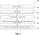
FIG. 3 shows a block diagram of a method for adjusting temperature measurement according to a thermal resistance. - Note that figures are not drawn to scale. Intermediate steps between figure transitions have been omitted so as not to obfuscate the disclosure. Those intermediate steps are known to a person skilled in the art.
- Many well-known manufacturing steps, components, and connectors have been omitted or not described in detail in the description so as not to obfuscate the present disclosure.
- The embodiments described herein includes an integrated circuit (IC) for measuring voltage and temperature of a battery cell in the pack of cells. The ICs connected to different battery cells may communicate with each other and with the pack controller via a communication link. The IC includes a communication module to effectuate communication with the pack controller. The IC may also include a controller that can be programmed to collect temperature and voltage data at preset intervals and also to execute commands received from the pack controller.
- All the circuits in the IC consume a (constant) current, therefore the internal power dissipation will cause the internal temperature to be higher than the battery temperature, so an accurate measurement is not possible. The quality of the thermal coupling / thermal resistance is not known beforehand, and may be different for each cell.
- The embodiments described herein are advantageous because a separate thermistor or NTC along with associated wiring is not needed to measure battery temperature. The temperature is measured by a temperature sensor embodied inside the same IC that is used for voltage measurement and communication with the battery pack controller. However, since internal components of the IC consume current and consequently dissipate heat, the temperature sensed by the temperature sensor includes rise in temperature due to self-heating of the IC. To offset the temperature generated by self-heating of the IC, during the calibration process, the thermal resistance between the IC and the battery contact is calculated and stored. The thermal resistance is then used by either the IC or the pack controller to subtract the temperature rise caused by self-heating of the IC to derive an accurate temperature at the battery terminal. Measurement of an accurate temperature may be needed to efficiently and optimally charge the battery.
-
Figure 1 shows a block diagram of anIC 100 mounted on abattery connection 108 through ametallic lead frame 106. The IC 100 includes avoltage sensor 102. Thevoltage sensor 102 may include an analog to digital converter that produces a digital output of a voltage drop across a resistor that is coupled to the voltage terminal. The IC 100 also includes an on-chip digital temperature sensor (DTS) 104. The DTS provides a digital output that represents ambient temperature of the IC die-pad. The temperature sensed by the DTS may also be, at least roughly within an acceptable margin of error, the temperature of at thebattery terminal 108. Voltage sensor and DTS are well known in the art, therefore a detailed structural description is being omitted. - However, when the
voltage sensor 102 is operational, the included components of thevoltage sensor 102 and other components of theIC 100 may dissipate some heat and will cause a rise in temperature of the die-pad. The value of this temperature rise needs to be calculated, at least at calibration time of each battery cell. In some examples, even when the IC 100 is mounted in close thermal contact to thebattery terminal 108, there may still be a thermal resistance up to 10 kelvin per watt. Each cell may have a different thermal resistance on thevoltage sensor 102 tobattery terminal 108 path as depicted by theline 112. This thermal resistance (R2) needs to be calculated for each IC mounting. The thermal resistance R2 is the temperature difference across theIC 100 and its coupling to thebattery terminal 108 when a unit of heat energy flows through the coupling in unit time. It is the reciprocal of thermal conductance. - With R2 known, the output of the
DTS 104 can be adjusted to compensate for self-heating that will be in proportion to R2 and the voltage measurement provided by thevoltage sensor 102. The value of R2 for eachIC 100 mounted on the battery terminal may be stored in the pack controller so that the pack controller may adjust temperature measurement received from theDTS 104 according to R2 and the voltage measurement. - The battery charging system includes a programmable current source that can be controlled to provide cell balancing where a particular amount of current may be used (for example, for charging the battery cell) based on the voltage measurement provided by the
voltage sensor 102. During the initial calculations of R2, a temperature T1 is measured by theDTS 104 at a current I1 applied to thevoltage sensor 102 to activate thevoltage sensor 102. Another temperature T2 is measured by theDTS 104 when the current I2 is applied to thevoltage sensor 102. The thermal resistance R2 can then be estimated using the formula R2 = (T2 -T1) / ( I2- I1 ) ∗ Vbat, where Vbat is the supply voltage of theIC 100. - The
voltage sensor 102 includes a digital to analog converter (DAC). In one example, the internal components of the IC consume approximately 10-30 milliamp current. However, the DAC may consume 150-300 milliamp. Therefore, the DAC contributes significantly more to self-heating of theIC 100. During the calibration step, in some examples, the programmable current source is used to measure the temperature using theDTS 104 at a normal current when theIC 100 is not being used for voltage measurement and at a current that loads the DAC. Prior to taking T2 current measurement, the process waits for a preselected time to allow the temperature to stabilize. In some examples, thevoltage sensor 102 is embodied at one end of the die-pad (i.e., the silicon on in which the components of theIC 100 are fabricated) and theDTS 104 is fabricated on the opposite side from thevoltage sensor 102. - Self-heating typically may raise the temperature measured by the
DTS 104 by 2-4 kelvin. However, the temperature accuracy required in many of the battery applications in approximately 1 kelvin. The embodiments described herein will at the very least comply with the accuracy requirements of most typical applications. - To derive the temperature rise due to self-heating of the
IC 100 during normal operating conditions, the power (P) is calculated by multiplying the output of thevoltage sensor 102 by the current the current being supplied by the battery. This current is known through current measurements (alternatively, the supply current of theIC 100 may be designed to have a fixed value). Finally, the temperature rise due to self-heating can be derived using the formula ΔT = P x R2. This value is then subtracted from the temperature sensed by theDTS 104 to derive the temperature at thebattery terminal 108. -
Figure 2 shows amethod 200 for calibrating theIC 100 to determine a thermal resistance between theIC 100 and thebattery terminal 108. Accordingly, atstep 202, theIC 102 is mounted on thebattery terminal 108. Atstep 204, theIC 100 is activated by passing the current I1 and the temperature (T1) is measured through theDTS 104. Atstep 206, the current I2 that is different from the current Ii, is used and again the temperature (T2) is measured using theDTS 104. Atstep 208, the battery voltage (Vbat) is measured using thevoltage sensor 102. Atstep 210, the thermal resistance R2 is estimated using the formula R2 = (T2 -T1) / ( I2- I1 ) ∗ Vbat (theIC 100 supply voltage). Atstep 212, R2 is stored either in theIC 100 or in a pack controller coupled to theIC 100. -
Figure 3 is amethod 300 for adjusting the temperature measured by theDTS 104 accounting to the stored thermal resistance R2 for theIC 100. Accordingly, atstep 302, the temperature is measured using theDTS 104. This measurement may be effectuated when a request is received from the pack controller coupled to theIC 100. In another example, theIC 100 can be programmed to measure the temperature at preselected intervals and transmit the measurement to the pack controller. Atstep 304, the voltage at thebattery terminal 108 is measured using thevoltage sensor 102. The current being used to charge the battery or the current being drawn from the battery is known as it can be measured using a current sensor. Atstep 306, the power is calculated by multiplying the battery voltage and the current. Atstep 308, the calculated power is multiplied by the thermal resistance R2 to derive self-heating contribution to the temperature measurement atstep 302, and atstep 310, the self-heating contribution temperature is subtracted from the temperature measured atstep 302. It may be noted that in some examples, the calculations described above may be performed at the pack controller instead on in theIC 100. In some embodiments, theIC 100 may optionally include aprocessor 114 to perform calibration and temperature adjustment calculations as described above. In other examples, the pack controller may include a processor to perform some or all calculations described herein. - While one or more implementations have been described by way of example and in terms of the specific embodiments, it is to be understood that one or more implementations are not limited to the disclosed embodiments. To the contrary, it is intended to cover various modifications and similar arrangements as would be apparent to those skilled in the art. Therefore, the scope of the appended claims should be accorded the broadest interpretation so as to encompass all such modifications and similar arrangements.
- The use of the terms "a" and "an" and "the" and similar referents in the context of describing the subject matter (particularly in the context of the following claims) are to be construed to cover both the singular and the plural, unless otherwise indicated herein or clearly contradicted by context. Recitation of ranges of values herein are merely intended to serve as a shorthand method of referring individually to each separate value falling within the range, unless otherwise indicated herein, and each separate value is incorporated into the specification as if it were individually recited herein. Furthermore, the foregoing description is for the purpose of illustration only, and not for the purpose of limitation, as the scope of protection sought is defined by the claims as set forth hereinafter together with any equivalents thereof entitled to. The use of any and all examples, or exemplary language (e.g., "such as") provided herein, is intended merely to better illustrate the subject matter and does not pose a limitation on the scope of the subject matter unless otherwise claimed. The use of the term "based on" and other like phrases indicating a condition for bringing about a result, both in the claims and in the written description, is not intended to foreclose any other conditions that bring about that result. No language in the specification should be construed as indicating any non-claimed element as essential to the practice of the invention as claimed.
- Preferred embodiments are described herein, including the best mode known to the inventor for carrying out the claimed subject matter. Of course, variations of those preferred embodiments will become apparent to those of ordinary skill in the art upon reading the foregoing description. The inventor expects skilled artisans to employ such variations as appropriate, and the inventor intends for the claimed subject matter to be practiced otherwise than as specifically described herein. Accordingly, this claimed subject matter includes all modifications and equivalents of the subject matter recited in the claims appended hereto as permitted by applicable law. Moreover, any combination of the above-described elements in all possible variations thereof is encompassed unless otherwise indicated herein or otherwise clearly contradicted by context.
Claims (10)
- A method for measuring a battery temperature using a temperature sensor embodied in a battery monitoring integrated circuit, characterized in that the method comprisesperforming calibration to calculate a thermal resistance between the battery monitoring integrated circuit (100) that includes a voltage sensor (102), and a terminal of a battery (108), wherein the performing the calibration includes mounting the battery monitoring integrated circuit on the terminal through a metallic lead frame (106);measuring a temperature using the temperature sensor (104);measuring a voltage at the terminal or at a supply pin of the battery monitoring integrated circuit while a current is being used to charge or discharge the battery;calculating a power by multiplying the voltage and the current;calculating a self-heating temperature adjustment to the temperature by multiplying the power and the thermal resistance.
- The method of claim 1, wherein the performing the calibration further includes drawing a first current (I1) from the battery and measuring a first temperature (T1) using the temperature sensor.
- The method of claim 2, wherein the performing the calibration further includes drawing a second current (I2) from the battery that is different from the first current and measuring a second temperature (T2) using the temperature sensor.
- The method of claim 3, wherein the performing the calibration further includes measuring a battery voltage (Vbat) at the terminal.
- The method of claim 4, wherein the thermal resistance is calculating using a formula R2 = (T2 -T1) / ( I2- I1 ) ∗ Vbat.
- The method of claim 4, further including storing the thermal resistance.
- The method of claim 6, wherein the thermal resistance is stored in a pack controller coupled to the battery monitoring integrated circuit.
- The method of claim 6, wherein the thermal resistance is stored in the battery monitoring integrated circuit.
- A battery monitoring integrated circuit (100), characterized by comprising:a voltage sensor (102) to measure a voltage at a battery terminal;a temperature sensor (104) for measuring temperature of inside the battery monitoring integrated circuit; anda processor (114) configured to perform the method as in claim 1.
- The battery monitoring integrated circuit of claim 9, wherein the voltage sensor is embodied on one side of the battery monitoring integrated circuit and the temperature sensor is embodied on an opposite side from the voltage sensor.
Applications Claiming Priority (1)
| Application Number | Priority Date | Filing Date | Title |
|---|---|---|---|
| US16/281,662 US11515585B2 (en) | 2019-02-21 | 2019-02-21 | Accurate battery temperature measurement by compensating self heating |
Publications (2)
| Publication Number | Publication Date |
|---|---|
| EP3699565A1 EP3699565A1 (en) | 2020-08-26 |
| EP3699565B1 true EP3699565B1 (en) | 2022-07-27 |
Family
ID=69055783
Family Applications (1)
| Application Number | Title | Priority Date | Filing Date |
|---|---|---|---|
| EP19219904.0A Active EP3699565B1 (en) | 2019-02-21 | 2019-12-27 | Accurate battery temperature measurement by compensating self heating |
Country Status (4)
| Country | Link |
|---|---|
| US (1) | US11515585B2 (en) |
| EP (1) | EP3699565B1 (en) |
| JP (1) | JP6864069B2 (en) |
| CN (1) | CN111596216B (en) |
Families Citing this family (4)
| Publication number | Priority date | Publication date | Assignee | Title |
|---|---|---|---|---|
| CN114814587B (en) * | 2021-01-29 | 2025-09-19 | 北京小米移动软件有限公司 | Battery temperature detection method, battery temperature detection device, and storage medium |
| CN114374010B (en) * | 2022-01-10 | 2023-08-01 | 浙江大学嘉兴研究院 | Method for measuring heat generation capacity of cylindrical lithium ion battery |
| CN114583301B (en) * | 2022-04-29 | 2022-08-23 | 国网浙江省电力有限公司电力科学研究院 | Power station thermal runaway early warning method and system based on safety characteristic parameter representation system |
| CN117629455B (en) * | 2022-08-10 | 2026-04-28 | 上海智能新能源汽车科创功能平台有限公司 | A method, apparatus, device, and storage medium for detecting the self-heating temperature of a battery. |
Family Cites Families (17)
| Publication number | Priority date | Publication date | Assignee | Title |
|---|---|---|---|---|
| JPH08149711A (en) * | 1994-11-18 | 1996-06-07 | Toshiba Corp | Charger for wireless communication device |
| US6518782B1 (en) * | 2000-08-29 | 2003-02-11 | Delta Design, Inc. | Active power monitoring using externally located current sensors |
| DE102005004998B4 (en) | 2005-02-03 | 2008-08-28 | Vb Autobatterie Gmbh & Co. Kgaa | Device and method for determining the temperature in an electric battery |
| JP5008863B2 (en) | 2005-11-30 | 2012-08-22 | プライムアースEvエナジー株式会社 | Secondary battery control device, secondary battery deterioration determination method using secondary battery temperature estimation method |
| US7514904B2 (en) | 2005-12-20 | 2009-04-07 | Caterpillar Inc. | System and method for determining battery temperature |
| JP2008008677A (en) * | 2006-06-27 | 2008-01-17 | Espec Corp | Method of measuring temperature of electric element and load testing system |
| DE102007025806B3 (en) | 2007-06-02 | 2008-06-26 | Dräger Safety AG & Co. KGaA | Animal's body temperature measuring device, has evaluating device in which temperature is calculated based on formula depending on temporal change of sensor temperature, to form temperature corrective value |
| US8831904B2 (en) * | 2009-08-05 | 2014-09-09 | Texas Instruments Incorporated | Cell based temperature monitoring |
| JP2011133418A (en) * | 2009-12-25 | 2011-07-07 | Toyota Industries Corp | Battery-pack monitoring circuit and battery cell unit |
| JP5347186B2 (en) * | 2010-04-26 | 2013-11-20 | 株式会社小松製作所 | Temperature detecting method and apparatus for power storage device, and temperature detecting device for power storage device in hybrid construction machine |
| JP5926495B2 (en) * | 2011-04-05 | 2016-05-25 | 矢崎総業株式会社 | Shunt resistance type current sensor |
| JP5683710B2 (en) * | 2011-09-08 | 2015-03-11 | 日立オートモティブシステムズ株式会社 | Battery system monitoring device |
| JP6157088B2 (en) * | 2012-11-07 | 2017-07-05 | ルネサスエレクトロニクス株式会社 | Battery control IC and control method thereof |
| EP2818967B1 (en) * | 2013-06-28 | 2018-08-22 | Dialog Semiconductor GmbH | Device and method for determining an operating temperature of an electronic component |
| DE102015209612A1 (en) * | 2015-05-26 | 2016-12-01 | Saint-Augustin Canada Electric Inc. | Method for testing the chip attachment of a photovoltaic cell array |
| JP6411318B2 (en) * | 2015-12-09 | 2018-10-24 | 本田技研工業株式会社 | Charging current setting method, charging method, charging device and actuator |
| CN205863332U (en) * | 2016-07-29 | 2017-01-04 | 泰科电子(上海)有限公司 | Temperature measurement component, electric appliance component, battery bag connect assembly and automobile batteries bag |
-
2019
- 2019-02-21 US US16/281,662 patent/US11515585B2/en active Active
- 2019-10-18 CN CN201910993914.5A patent/CN111596216B/en active Active
- 2019-12-24 JP JP2019232287A patent/JP6864069B2/en not_active Expired - Fee Related
- 2019-12-27 EP EP19219904.0A patent/EP3699565B1/en active Active
Also Published As
| Publication number | Publication date |
|---|---|
| US20200274207A1 (en) | 2020-08-27 |
| JP2020134512A (en) | 2020-08-31 |
| JP6864069B2 (en) | 2021-04-21 |
| CN111596216B (en) | 2024-06-07 |
| US11515585B2 (en) | 2022-11-29 |
| EP3699565A1 (en) | 2020-08-26 |
| CN111596216A (en) | 2020-08-28 |
Similar Documents
| Publication | Publication Date | Title |
|---|---|---|
| EP3699565A1 (en) | Accurate battery temperature measurement by compensating self heating | |
| TWI474529B (en) | Battery charging and discharging system | |
| US9478831B2 (en) | Battery comprising a battery cell with an external and an integrated temperature sensor, and a method for operating said battery | |
| EP2818967B1 (en) | Device and method for determining an operating temperature of an electronic component | |
| US7514904B2 (en) | System and method for determining battery temperature | |
| EP2482050A2 (en) | Intake air temperature sensor and thermal airflow meter including the same | |
| US20060164111A1 (en) | Temperature sensing and prediction in IC sockets | |
| US20070089503A1 (en) | Thermal airflow meter | |
| US20110106476A1 (en) | Methods and systems for thermistor temperature processing | |
| CN109416391B (en) | Method for determining the internal resistance of a battery cell, battery module and device | |
| KR20070114310A (en) | Sensing and Predicting Temperature of IC Sockets | |
| CN108107369B (en) | battery monitoring circuit | |
| US11692881B2 (en) | Temperature sensor thermal contact testing method and circuit | |
| US11639967B2 (en) | Sensor system for a battery module | |
| US20190195908A1 (en) | Wind speed measuring device and airflow measuring device | |
| CN112242729B (en) | Semiconductor device with a semiconductor layer having a plurality of semiconductor layers | |
| JP2004132351A (en) | Automotive electronics lead frame | |
| JP2007109536A (en) | Temperature detector | |
| US20250087769A1 (en) | Battery Management System, Battery Pack and Method for Controlling Discharge of at Least One Battery Cell | |
| JP7260433B2 (en) | Management device, power supply system | |
| CN215348366U (en) | a liquid heater | |
| KR102512061B1 (en) | Sensor system for battery module | |
| CN117294261B (en) | Aging Compensation of Current Sensing Amplifier Based on Multi-Resistors | |
| JP6532810B2 (en) | Flow sensor | |
| CN220252039U (en) | Current detection assembly |
Legal Events
| Date | Code | Title | Description |
|---|---|---|---|
| PUAI | Public reference made under article 153(3) epc to a published international application that has entered the european phase |
Free format text: ORIGINAL CODE: 0009012 |
|
| STAA | Information on the status of an ep patent application or granted ep patent |
Free format text: STATUS: THE APPLICATION HAS BEEN PUBLISHED |
|
| AK | Designated contracting states |
Kind code of ref document: A1 Designated state(s): AL AT BE BG CH CY CZ DE DK EE ES FI FR GB GR HR HU IE IS IT LI LT LU LV MC MK MT NL NO PL PT RO RS SE SI SK SM TR |
|
| AX | Request for extension of the european patent |
Extension state: BA ME |
|
| STAA | Information on the status of an ep patent application or granted ep patent |
Free format text: STATUS: REQUEST FOR EXAMINATION WAS MADE |
|
| 17P | Request for examination filed |
Effective date: 20210127 |
|
| RBV | Designated contracting states (corrected) |
Designated state(s): AL AT BE BG CH CY CZ DE DK EE ES FI FR GB GR HR HU IE IS IT LI LT LU LV MC MK MT NL NO PL PT RO RS SE SI SK SM TR |
|
| GRAP | Despatch of communication of intention to grant a patent |
Free format text: ORIGINAL CODE: EPIDOSNIGR1 |
|
| STAA | Information on the status of an ep patent application or granted ep patent |
Free format text: STATUS: GRANT OF PATENT IS INTENDED |
|
| INTG | Intention to grant announced |
Effective date: 20220309 |
|
| GRAS | Grant fee paid |
Free format text: ORIGINAL CODE: EPIDOSNIGR3 |
|
| GRAA | (expected) grant |
Free format text: ORIGINAL CODE: 0009210 |
|
| STAA | Information on the status of an ep patent application or granted ep patent |
Free format text: STATUS: THE PATENT HAS BEEN GRANTED |
|
| AK | Designated contracting states |
Kind code of ref document: B1 Designated state(s): AL AT BE BG CH CY CZ DE DK EE ES FI FR GB GR HR HU IE IS IT LI LT LU LV MC MK MT NL NO PL PT RO RS SE SI SK SM TR |
|
| REG | Reference to a national code |
Ref country code: CH Ref legal event code: EP |
|
| REG | Reference to a national code |
Ref country code: DE Ref legal event code: R096 Ref document number: 602019017457 Country of ref document: DE |
|
| REG | Reference to a national code |
Ref country code: AT Ref legal event code: REF Ref document number: 1507354 Country of ref document: AT Kind code of ref document: T Effective date: 20220815 |
|
| REG | Reference to a national code |
Ref country code: IE Ref legal event code: FG4D |
|
| REG | Reference to a national code |
Ref country code: LT Ref legal event code: MG9D |
|
| REG | Reference to a national code |
Ref country code: NL Ref legal event code: MP Effective date: 20220727 |
|
| PG25 | Lapsed in a contracting state [announced via postgrant information from national office to epo] |
Ref country code: SE Free format text: LAPSE BECAUSE OF FAILURE TO SUBMIT A TRANSLATION OF THE DESCRIPTION OR TO PAY THE FEE WITHIN THE PRESCRIBED TIME-LIMIT Effective date: 20220727 Ref country code: RS Free format text: LAPSE BECAUSE OF FAILURE TO SUBMIT A TRANSLATION OF THE DESCRIPTION OR TO PAY THE FEE WITHIN THE PRESCRIBED TIME-LIMIT Effective date: 20220727 Ref country code: PT Free format text: LAPSE BECAUSE OF FAILURE TO SUBMIT A TRANSLATION OF THE DESCRIPTION OR TO PAY THE FEE WITHIN THE PRESCRIBED TIME-LIMIT Effective date: 20221128 Ref country code: NO Free format text: LAPSE BECAUSE OF FAILURE TO SUBMIT A TRANSLATION OF THE DESCRIPTION OR TO PAY THE FEE WITHIN THE PRESCRIBED TIME-LIMIT Effective date: 20221027 Ref country code: NL Free format text: LAPSE BECAUSE OF FAILURE TO SUBMIT A TRANSLATION OF THE DESCRIPTION OR TO PAY THE FEE WITHIN THE PRESCRIBED TIME-LIMIT Effective date: 20220727 Ref country code: LV Free format text: LAPSE BECAUSE OF FAILURE TO SUBMIT A TRANSLATION OF THE DESCRIPTION OR TO PAY THE FEE WITHIN THE PRESCRIBED TIME-LIMIT Effective date: 20220727 Ref country code: LT Free format text: LAPSE BECAUSE OF FAILURE TO SUBMIT A TRANSLATION OF THE DESCRIPTION OR TO PAY THE FEE WITHIN THE PRESCRIBED TIME-LIMIT Effective date: 20220727 Ref country code: FI Free format text: LAPSE BECAUSE OF FAILURE TO SUBMIT A TRANSLATION OF THE DESCRIPTION OR TO PAY THE FEE WITHIN THE PRESCRIBED TIME-LIMIT Effective date: 20220727 Ref country code: ES Free format text: LAPSE BECAUSE OF FAILURE TO SUBMIT A TRANSLATION OF THE DESCRIPTION OR TO PAY THE FEE WITHIN THE PRESCRIBED TIME-LIMIT Effective date: 20220727 |
|
| REG | Reference to a national code |
Ref country code: AT Ref legal event code: MK05 Ref document number: 1507354 Country of ref document: AT Kind code of ref document: T Effective date: 20220727 |
|
| PG25 | Lapsed in a contracting state [announced via postgrant information from national office to epo] |
Ref country code: PL Free format text: LAPSE BECAUSE OF FAILURE TO SUBMIT A TRANSLATION OF THE DESCRIPTION OR TO PAY THE FEE WITHIN THE PRESCRIBED TIME-LIMIT Effective date: 20220727 Ref country code: IS Free format text: LAPSE BECAUSE OF FAILURE TO SUBMIT A TRANSLATION OF THE DESCRIPTION OR TO PAY THE FEE WITHIN THE PRESCRIBED TIME-LIMIT Effective date: 20221127 Ref country code: HR Free format text: LAPSE BECAUSE OF FAILURE TO SUBMIT A TRANSLATION OF THE DESCRIPTION OR TO PAY THE FEE WITHIN THE PRESCRIBED TIME-LIMIT Effective date: 20220727 Ref country code: GR Free format text: LAPSE BECAUSE OF FAILURE TO SUBMIT A TRANSLATION OF THE DESCRIPTION OR TO PAY THE FEE WITHIN THE PRESCRIBED TIME-LIMIT Effective date: 20221028 |
|
| PG25 | Lapsed in a contracting state [announced via postgrant information from national office to epo] |
Ref country code: SM Free format text: LAPSE BECAUSE OF FAILURE TO SUBMIT A TRANSLATION OF THE DESCRIPTION OR TO PAY THE FEE WITHIN THE PRESCRIBED TIME-LIMIT Effective date: 20220727 Ref country code: RO Free format text: LAPSE BECAUSE OF FAILURE TO SUBMIT A TRANSLATION OF THE DESCRIPTION OR TO PAY THE FEE WITHIN THE PRESCRIBED TIME-LIMIT Effective date: 20220727 Ref country code: DK Free format text: LAPSE BECAUSE OF FAILURE TO SUBMIT A TRANSLATION OF THE DESCRIPTION OR TO PAY THE FEE WITHIN THE PRESCRIBED TIME-LIMIT Effective date: 20220727 Ref country code: CZ Free format text: LAPSE BECAUSE OF FAILURE TO SUBMIT A TRANSLATION OF THE DESCRIPTION OR TO PAY THE FEE WITHIN THE PRESCRIBED TIME-LIMIT Effective date: 20220727 Ref country code: AT Free format text: LAPSE BECAUSE OF FAILURE TO SUBMIT A TRANSLATION OF THE DESCRIPTION OR TO PAY THE FEE WITHIN THE PRESCRIBED TIME-LIMIT Effective date: 20220727 |
|
| REG | Reference to a national code |
Ref country code: DE Ref legal event code: R097 Ref document number: 602019017457 Country of ref document: DE |
|
| PG25 | Lapsed in a contracting state [announced via postgrant information from national office to epo] |
Ref country code: SK Free format text: LAPSE BECAUSE OF FAILURE TO SUBMIT A TRANSLATION OF THE DESCRIPTION OR TO PAY THE FEE WITHIN THE PRESCRIBED TIME-LIMIT Effective date: 20220727 Ref country code: EE Free format text: LAPSE BECAUSE OF FAILURE TO SUBMIT A TRANSLATION OF THE DESCRIPTION OR TO PAY THE FEE WITHIN THE PRESCRIBED TIME-LIMIT Effective date: 20220727 |
|
| PGFP | Annual fee paid to national office [announced via postgrant information from national office to epo] |
Ref country code: IT Payment date: 20221231 Year of fee payment: 4 |
|
| PLBE | No opposition filed within time limit |
Free format text: ORIGINAL CODE: 0009261 |
|
| STAA | Information on the status of an ep patent application or granted ep patent |
Free format text: STATUS: NO OPPOSITION FILED WITHIN TIME LIMIT |
|
| P01 | Opt-out of the competence of the unified patent court (upc) registered |
Effective date: 20230508 |
|
| PG25 | Lapsed in a contracting state [announced via postgrant information from national office to epo] |
Ref country code: AL Free format text: LAPSE BECAUSE OF FAILURE TO SUBMIT A TRANSLATION OF THE DESCRIPTION OR TO PAY THE FEE WITHIN THE PRESCRIBED TIME-LIMIT Effective date: 20220727 |
|
| 26N | No opposition filed |
Effective date: 20230502 |
|
| REG | Reference to a national code |
Ref country code: CH Ref legal event code: PL |
|
| REG | Reference to a national code |
Ref country code: BE Ref legal event code: MM Effective date: 20221231 |
|
| PG25 | Lapsed in a contracting state [announced via postgrant information from national office to epo] |
Ref country code: SI Free format text: LAPSE BECAUSE OF FAILURE TO SUBMIT A TRANSLATION OF THE DESCRIPTION OR TO PAY THE FEE WITHIN THE PRESCRIBED TIME-LIMIT Effective date: 20220727 Ref country code: LU Free format text: LAPSE BECAUSE OF NON-PAYMENT OF DUE FEES Effective date: 20221227 |
|
| PG25 | Lapsed in a contracting state [announced via postgrant information from national office to epo] |
Ref country code: LI Free format text: LAPSE BECAUSE OF NON-PAYMENT OF DUE FEES Effective date: 20221231 Ref country code: IE Free format text: LAPSE BECAUSE OF NON-PAYMENT OF DUE FEES Effective date: 20221227 Ref country code: CH Free format text: LAPSE BECAUSE OF NON-PAYMENT OF DUE FEES Effective date: 20221231 |
|
| PG25 | Lapsed in a contracting state [announced via postgrant information from national office to epo] |
Ref country code: BE Free format text: LAPSE BECAUSE OF NON-PAYMENT OF DUE FEES Effective date: 20221231 |
|
| PG25 | Lapsed in a contracting state [announced via postgrant information from national office to epo] |
Ref country code: CY Free format text: LAPSE BECAUSE OF FAILURE TO SUBMIT A TRANSLATION OF THE DESCRIPTION OR TO PAY THE FEE WITHIN THE PRESCRIBED TIME-LIMIT Effective date: 20220727 |
|
| PG25 | Lapsed in a contracting state [announced via postgrant information from national office to epo] |
Ref country code: MK Free format text: LAPSE BECAUSE OF FAILURE TO SUBMIT A TRANSLATION OF THE DESCRIPTION OR TO PAY THE FEE WITHIN THE PRESCRIBED TIME-LIMIT Effective date: 20220727 Ref country code: HU Free format text: LAPSE BECAUSE OF FAILURE TO SUBMIT A TRANSLATION OF THE DESCRIPTION OR TO PAY THE FEE WITHIN THE PRESCRIBED TIME-LIMIT; INVALID AB INITIO Effective date: 20191227 |
|
| PG25 | Lapsed in a contracting state [announced via postgrant information from national office to epo] |
Ref country code: MC Free format text: LAPSE BECAUSE OF FAILURE TO SUBMIT A TRANSLATION OF THE DESCRIPTION OR TO PAY THE FEE WITHIN THE PRESCRIBED TIME-LIMIT Effective date: 20220727 |
|
| PG25 | Lapsed in a contracting state [announced via postgrant information from national office to epo] |
Ref country code: MC Free format text: LAPSE BECAUSE OF FAILURE TO SUBMIT A TRANSLATION OF THE DESCRIPTION OR TO PAY THE FEE WITHIN THE PRESCRIBED TIME-LIMIT Effective date: 20220727 |
|
| PG25 | Lapsed in a contracting state [announced via postgrant information from national office to epo] |
Ref country code: BG Free format text: LAPSE BECAUSE OF FAILURE TO SUBMIT A TRANSLATION OF THE DESCRIPTION OR TO PAY THE FEE WITHIN THE PRESCRIBED TIME-LIMIT Effective date: 20220727 |
|
| PG25 | Lapsed in a contracting state [announced via postgrant information from national office to epo] |
Ref country code: MT Free format text: LAPSE BECAUSE OF FAILURE TO SUBMIT A TRANSLATION OF THE DESCRIPTION OR TO PAY THE FEE WITHIN THE PRESCRIBED TIME-LIMIT Effective date: 20220727 |
|
| PGFP | Annual fee paid to national office [announced via postgrant information from national office to epo] |
Ref country code: DE Payment date: 20241217 Year of fee payment: 6 |
|
| PGFP | Annual fee paid to national office [announced via postgrant information from national office to epo] |
Ref country code: GB Payment date: 20241212 Year of fee payment: 6 |
|
| PGFP | Annual fee paid to national office [announced via postgrant information from national office to epo] |
Ref country code: FR Payment date: 20241223 Year of fee payment: 6 |
|
| PG25 | Lapsed in a contracting state [announced via postgrant information from national office to epo] |
Ref country code: TR Free format text: LAPSE BECAUSE OF FAILURE TO SUBMIT A TRANSLATION OF THE DESCRIPTION OR TO PAY THE FEE WITHIN THE PRESCRIBED TIME-LIMIT Effective date: 20220727 |