EP3699520A1 - Refrigeration appliance - Google Patents
Refrigeration appliance Download PDFInfo
- Publication number
- EP3699520A1 EP3699520A1 EP20152895.7A EP20152895A EP3699520A1 EP 3699520 A1 EP3699520 A1 EP 3699520A1 EP 20152895 A EP20152895 A EP 20152895A EP 3699520 A1 EP3699520 A1 EP 3699520A1
- Authority
- EP
- European Patent Office
- Prior art keywords
- groove
- air duct
- liner
- refrigeration appliance
- side wall
- Prior art date
- Legal status (The legal status is an assumption and is not a legal conclusion. Google has not performed a legal analysis and makes no representation as to the accuracy of the status listed.)
- Granted
Links
Images



Classifications
-
- F—MECHANICAL ENGINEERING; LIGHTING; HEATING; WEAPONS; BLASTING
- F25—REFRIGERATION OR COOLING; COMBINED HEATING AND REFRIGERATION SYSTEMS; HEAT PUMP SYSTEMS; MANUFACTURE OR STORAGE OF ICE; LIQUEFACTION SOLIDIFICATION OF GASES
- F25D—REFRIGERATORS; COLD ROOMS; ICE-BOXES; COOLING OR FREEZING APPARATUS NOT OTHERWISE PROVIDED FOR
- F25D17/00—Arrangements for circulating cooling fluids; Arrangements for circulating gas, e.g. air, within refrigerated spaces
- F25D17/04—Arrangements for circulating cooling fluids; Arrangements for circulating gas, e.g. air, within refrigerated spaces for circulating air, e.g. by convection
- F25D17/06—Arrangements for circulating cooling fluids; Arrangements for circulating gas, e.g. air, within refrigerated spaces for circulating air, e.g. by convection by forced circulation
- F25D17/062—Arrangements for circulating cooling fluids; Arrangements for circulating gas, e.g. air, within refrigerated spaces for circulating air, e.g. by convection by forced circulation in household refrigerators
-
- F—MECHANICAL ENGINEERING; LIGHTING; HEATING; WEAPONS; BLASTING
- F25—REFRIGERATION OR COOLING; COMBINED HEATING AND REFRIGERATION SYSTEMS; HEAT PUMP SYSTEMS; MANUFACTURE OR STORAGE OF ICE; LIQUEFACTION SOLIDIFICATION OF GASES
- F25D—REFRIGERATORS; COLD ROOMS; ICE-BOXES; COOLING OR FREEZING APPARATUS NOT OTHERWISE PROVIDED FOR
- F25D2317/00—Details or arrangements for circulating cooling fluids; Details or arrangements for circulating gas, e.g. air, within refrigerated spaces, not provided for in other groups of this subclass
- F25D2317/06—Details or arrangements for circulating cooling fluids; Details or arrangements for circulating gas, e.g. air, within refrigerated spaces, not provided for in other groups of this subclass with forced air circulation
- F25D2317/066—Details or arrangements for circulating cooling fluids; Details or arrangements for circulating gas, e.g. air, within refrigerated spaces, not provided for in other groups of this subclass with forced air circulation characterised by the air supply
- F25D2317/0664—Details or arrangements for circulating cooling fluids; Details or arrangements for circulating gas, e.g. air, within refrigerated spaces, not provided for in other groups of this subclass with forced air circulation characterised by the air supply from the side
-
- F—MECHANICAL ENGINEERING; LIGHTING; HEATING; WEAPONS; BLASTING
- F25—REFRIGERATION OR COOLING; COMBINED HEATING AND REFRIGERATION SYSTEMS; HEAT PUMP SYSTEMS; MANUFACTURE OR STORAGE OF ICE; LIQUEFACTION SOLIDIFICATION OF GASES
- F25D—REFRIGERATORS; COLD ROOMS; ICE-BOXES; COOLING OR FREEZING APPARATUS NOT OTHERWISE PROVIDED FOR
- F25D2317/00—Details or arrangements for circulating cooling fluids; Details or arrangements for circulating gas, e.g. air, within refrigerated spaces, not provided for in other groups of this subclass
- F25D2317/06—Details or arrangements for circulating cooling fluids; Details or arrangements for circulating gas, e.g. air, within refrigerated spaces, not provided for in other groups of this subclass with forced air circulation
- F25D2317/066—Details or arrangements for circulating cooling fluids; Details or arrangements for circulating gas, e.g. air, within refrigerated spaces, not provided for in other groups of this subclass with forced air circulation characterised by the air supply
- F25D2317/0665—Details or arrangements for circulating cooling fluids; Details or arrangements for circulating gas, e.g. air, within refrigerated spaces, not provided for in other groups of this subclass with forced air circulation characterised by the air supply from the top
Definitions
- Embodiments of the utility model relate to the technical field of household appliances, and in particular, to a refrigeration appliance.
- a fan is usually used to blow cold air to each compartment of the refrigerator for refrigeration.
- an air duct in the frost-free refrigerator usually needs to occupy space of a storage compartment, resulting in a relatively small volume of the storage compartment.
- Embodiments of the utility model are intended to reduce space occupied by an air duct in a storage compartment.
- the embodiments of the utility model provides a refrigeration appliance including a housing, a liner, and an air duct assembly configured to define an air duct, the liner being located inside the housing, a back wall of the liner being recessed toward the housing to form a groove, and the air duct being located in the groove.
- the back wall of the liner of the refrigeration appliance is recessed in a direction toward the housing to form the groove.
- the air duct assembly may define one air duct, and the air duct is disposed in the groove. Because the groove is formed, on a basis of a storage compartment formed in the liner, with the back wall recessed in the direction toward the housing, space occupied by the air duct in the storage compartment can be reduced. In addition, overall consistency inside the storage compartment of the refrigeration appliance may further be improved.
- the groove includes at least one curved side wall, two ends of the curved side wall being respectively connected to the back wall of the liner and a side wall of the groove.
- the curved side wall is used to guide air, so that an appearance of the storage compartment can be optimized, and integrity of the storage compartment can be improved.
- cold air is blown out through the curved side wall formed by the groove, to prevent air from hitting a side wall of the liner, thereby reducing air resistance and directing air forward.
- the curved side wall is tangent to the back wall of the liner, so that the air resistance can further be reduced, wind field can be optimized, a cooling speed in the storage compartment can be increased, thereby facilitating cooling of food materials.
- the curved side wall is tangent to the side wall of the groove, so that the air resistance can further be reduced, wind field can be optimized, a cooling speed in the storage compartment can be increased, thereby facilitating cooling of food materials.
- the groove includes a curved top wall being connected to a top wall of the liner.
- the curved top wall is tangent to the top wall of the liner.
- the air duct assembly includes a front cover plate and an air duct member, the air duct member being located between the front cover plate and a back wall of the groove.
- the front cover plate protrudes from a plane on which a notch of the groove is located.
- a distance by which the front cover plate protrudes from the plane on which the notch of the groove is located is not greater than 10 mm.
- a gap is provided between a side end of the front cover plate and the curved side wall of the groove for cold air to flow out.
- FIG. 1 is a schematic structural diagram of a refrigeration appliance according to an embodiment of the utility model.
- FIG. 2 is a cross-sectional view of FIG. 1 taken along a direction A-A.
- FIG. 3 is a partial enlarged view of FIG. 2 at I.
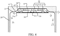
- FIG. 4 is a cross-sectional view of FIG. 1 taken along a direction B-B.
- FIG. 5 is a partial schematic structural diagram of a refrigeration appliance according to an embodiment of the utility model. A specific structure of the refrigeration appliance is described below with reference to FIG. 1 to FIG. 5 .
- a refrigeration appliance 100 may include a housing 10, a liner 20, and an air duct assembly 30.
- the liner 20 is located inside the housing 10.
- a portion of a back wall 21 of the liner 20 is recessed toward the housing 10 to form a groove 40.
- the air duct assembly 30 defines an air duct 50, the air duct 50 providing a flow passage for air blown by a fan, and the air duct 50 being located in the groove 40.
- the air duct assembly 30 may include a plurality of components, where some components may be located in the groove 40, and other components may be located outside the groove 40.
- the air duct assembly 30 includes an air duct member 32 and a front cover plate 31. The air duct member 32 is located in the groove 40, and the front cover plate 31 is located outside the groove 40.
- the groove 40 for accommodating the air duct 50 is formed by the portion of the back wall of the liner 20 being recessed in a direction toward the housing 10, so that there is no need to occupy too much space in the storage compartment. Therefore, in comparison to the prior art in which an air duct needs to be disposed in a storage compartment, space occupied by the air duct 50 in the storage compartment can be effectively reduced.
- the air duct assembly 30 configured to define the air duct 50 is at least partially located in the groove, that is, only a small portion of the components of the air duct assembly 30 may protrude from the groove 40, so that overall consistency in the storage compartment of the refrigeration appliance 100 can be improved.
- a manner in which the air duct 50 and the air duct assembly 30 provided in the embodiments of the utility model are arranged is used, so that a distance between the air duct assembly 30 and the liner 20 can be shortened, a distance between a glass shelf and the air duct assembly 30 can be reduced, and a volume of the refrigeration appliance 100 can be increased.
- the groove 40 includes at least one curved side wall 41. Two ends of the curved side wall 41 are respectively connected to the back wall 21 of the liner 20 and a side wall 43 of the groove 40.
- the groove 40 may include one curved side wall 41, or may include two curved side walls 41.
- a specific quantity of curved side walls 41 disposed in the groove 40 may be set according to factors such as a quantity of air outlets of the air duct assembly 30, a size or an arranging position of an air outlet of the air duct assembly 30.
- the disposed curved side wall 41 can guide air without needing to dispose additional air guide components, so that a quantity of components of the refrigeration appliance 100 can be reduced, and a structure of the refrigeration appliance 100 can be simplified.
- installation steps can be reduced, and costs of refrigeration appliance 100 can be reduced.
- the curved side wall 41 is tangent to the back wall 21 of the liner 20.
- air can be prevented from hitting a side wall of the liner 20, so that air resistance is reduced and air can be directed forward.
- air may be guided to a front end of the liner 20, that is, a region that is of the liner 20 and that is close to a door of a refrigerator, to optimize a wind field, thereby increasing a cooling speed in the storage compartment, and facilitating cooling of food materials.
- a direction of arrows in FIG. 2 and FIG. 4 is an approximate direction of cold air.
- the curved side wall 41 is tangent to the side wall 43 of the groove 40, and air can be guided out along the curved side wall 41 and in a direction in which the curved side wall 41 is tangent to the side wall 43 of the groove 40, to reduce the wind resistance, so that the air resistance can further be reduced, and the cooling speed in the storage compartment can be increased.
- the groove 40 may further include a curved top wall 42.
- the curved top wall 42 is connected to a top wall 22 of the liner 20.
- the curved top wall 42 is tangent to the top wall 22 of the liner 20, and cold air flowing out from the curved top wall 42 can be guided out from the curved top wall 42 and in a direction in which the curved top wall 42 is tangent to the top wall 22 of the liner 20, so that the air resistance can further be reduced, the wind field can be optimized, the cooling speed in the storage compartment can be increased, thereby facilitating the cooling of food materials.
- the curved side wall 41 or the curved top wall 42 is used to guide air, so that an appearance of the storage compartment can be optimized, and integrity of the storage compartment is improved.
- cold air is blown out through a curved surface presented by the groove 40, to prevent the air from hitting the side wall of the liner 20, thereby reducing the air resistance and directing air forward.
- the air duct assembly 30 includes the front cover plate 31 and the air duct member 32.
- the air duct member 32 is located between the front cover plate 31 and a back wall 45 of the groove 40.
- a gap is provided between a side end 31a of the front cover plate 31 and the curved side wall 41 of the groove 40 for cold air to flow out.
- the air duct member 32 is provided with an air outlet. When the fan operates, cold air is blown out through the air outlet, and under guidance of the curved side wall 41 or the curved top wall 42, cold air flows out through the gap between the side end 31a of the front cover plate 31 and the curved side wall 41 of the groove 40 and enters the storage compartment, and then returns to the air duct assembly 30 through a return air inlet disposed at bottom of the liner 20, so that a cycle is completed.
- several air outlets may be disposed at one side of the air duct member 32, or several air outlets may be disposed at two sides of the air duct member 32, or several air outlets may be disposed at a top of the air duct member 32, or air outlets may be disposed at two sides and the top of the air duct member 32.
- stiffeners 311 are disposed on the front cover plate 31.
- the air duct member 32 is located in the groove 40, and the front cover plate 31 is located outside the groove 40. It may be understood that the front cover plate 31 may also be disposed in the groove 40 according to an actual application requirement.
- the front cover plate 31 may protrude from a plane on which a notch of the groove 40 is located, so that overall consistency in the storage compartment of the refrigeration appliance 100 can be improved, thereby achieving a better overall effect of the storage compartment.
- the front cover plate 31 may be connected to the curved side wall 41 of the groove 40.
- a hook is disposed on the front cover plate 31, a slot corresponding to the hook is disposed on the curved side wall 41, and the front cover plate 31 is engaged with the curved side wall 41.
- the front cover plate 31 is connected to the side wall 43 of the groove 40.
- a distance d by which the front cover plate 31 protrudes from the plane on which the notch of the groove 40 is located is not greater than 10 mm.
- the distance by which the front cover plate 31 protrudes from the plane on which the notch of the groove 40 is located is 5 mm.
- the distance d by which the front cover plate 31 protrudes from the plane on which the notch of the groove 40 is located may be set based on an actual size, refrigerating capacity, and the like of the storage compartment of the refrigeration appliance 100.
- the air duct assembly 30 further includes a rear cover plate 33.
- the rear cover plate 33 is located between the air duct member 32 and the back wall 45 of the groove 40, and the rear cover plate 33 may be fixed to the back wall 45 of the groove 40.
- the air duct assembly 30 includes a seal, the seal being located between the air duct member 32 and the back wall 45 of the groove 40.
Landscapes
- Engineering & Computer Science (AREA)
- Chemical & Material Sciences (AREA)
- Combustion & Propulsion (AREA)
- Physics & Mathematics (AREA)
- Mechanical Engineering (AREA)
- Thermal Sciences (AREA)
- General Engineering & Computer Science (AREA)
- Cold Air Circulating Systems And Constructional Details In Refrigerators (AREA)
Abstract
Description
- Embodiments of the utility model relate to the technical field of household appliances, and in particular, to a refrigeration appliance.
- For a current frost-free refrigerator, a fan is usually used to blow cold air to each compartment of the refrigerator for refrigeration.
- However, an air duct in the frost-free refrigerator usually needs to occupy space of a storage compartment, resulting in a relatively small volume of the storage compartment.
- Embodiments of the utility model are intended to reduce space occupied by an air duct in a storage compartment.
- To solve the foregoing technical problem, the embodiments of the utility model provides a refrigeration appliance including a housing, a liner, and an air duct assembly configured to define an air duct, the liner being located inside the housing, a back wall of the liner being recessed toward the housing to form a groove, and the air duct being located in the groove.
- In comparison to the prior art, technical solutions of the embodiments of the utility model have the following beneficial effects.
- The back wall of the liner of the refrigeration appliance is recessed in a direction toward the housing to form the groove. The air duct assembly may define one air duct, and the air duct is disposed in the groove. Because the groove is formed, on a basis of a storage compartment formed in the liner, with the back wall recessed in the direction toward the housing, space occupied by the air duct in the storage compartment can be reduced. In addition, overall consistency inside the storage compartment of the refrigeration appliance may further be improved.
- Optionally, the groove includes at least one curved side wall, two ends of the curved side wall being respectively connected to the back wall of the liner and a side wall of the groove. The curved side wall is used to guide air, so that an appearance of the storage compartment can be optimized, and integrity of the storage compartment can be improved. In addition, cold air is blown out through the curved side wall formed by the groove, to prevent air from hitting a side wall of the liner, thereby reducing air resistance and directing air forward.
- Optionally, the curved side wall is tangent to the back wall of the liner, so that the air resistance can further be reduced, wind field can be optimized, a cooling speed in the storage compartment can be increased, thereby facilitating cooling of food materials.
- Optionally, the curved side wall is tangent to the side wall of the groove, so that the air resistance can further be reduced, wind field can be optimized, a cooling speed in the storage compartment can be increased, thereby facilitating cooling of food materials.
- Optionally, the groove includes a curved top wall being connected to a top wall of the liner.
- Optionally, the curved top wall is tangent to the top wall of the liner.
- Optionally, the air duct assembly includes a front cover plate and an air duct member, the air duct member being located between the front cover plate and a back wall of the groove.
- Optionally, the front cover plate protrudes from a plane on which a notch of the groove is located.
- Optionally, a distance by which the front cover plate protrudes from the plane on which the notch of the groove is located is not greater than 10 mm.
- Optionally, a gap is provided between a side end of the front cover plate and the curved side wall of the groove for cold air to flow out.
-
-
FIG. 1 is a schematic structural diagram of a refrigeration appliance according to an embodiment of the utility model; -
FIG. 2 is a cross-sectional view ofFIG. 1 taken along a direction A-A; -
FIG. 3 is a partial enlarged view ofFIG. 2 at I; -
FIG. 4 is a cross-sectional view ofFIG. 1 taken along a direction B-B; and -
FIG. 5 is a partial schematic structural diagram of a refrigeration appliance according to an embodiment of the utility model. - In order to make the foregoing objective, features, and advantages of the embodiments of the utility model more clearly and easier to understand, specific embodiments of the utility model are described in detail below with reference to the accompanying drawings.
-
FIG. 1 is a schematic structural diagram of a refrigeration appliance according to an embodiment of the utility model.FIG. 2 is a cross-sectional view ofFIG. 1 taken along a direction A-A.FIG. 3 is a partial enlarged view ofFIG. 2 at I.FIG. 4 is a cross-sectional view ofFIG. 1 taken along a direction B-B.FIG. 5 is a partial schematic structural diagram of a refrigeration appliance according to an embodiment of the utility model. A specific structure of the refrigeration appliance is described below with reference toFIG. 1 to FIG. 5 . - In specific implementation, a
refrigeration appliance 100 may include ahousing 10, aliner 20, and anair duct assembly 30. Theliner 20 is located inside thehousing 10. A portion of aback wall 21 of theliner 20 is recessed toward thehousing 10 to form agroove 40. Theair duct assembly 30 defines anair duct 50, theair duct 50 providing a flow passage for air blown by a fan, and theair duct 50 being located in thegroove 40. - In the embodiment of the utility model, the
air duct assembly 30 may include a plurality of components, where some components may be located in thegroove 40, and other components may be located outside thegroove 40. For example, theair duct assembly 30 includes anair duct member 32 and afront cover plate 31. Theair duct member 32 is located in thegroove 40, and thefront cover plate 31 is located outside thegroove 40. - The
groove 40 for accommodating theair duct 50 is formed by the portion of the back wall of theliner 20 being recessed in a direction toward thehousing 10, so that there is no need to occupy too much space in the storage compartment. Therefore, in comparison to the prior art in which an air duct needs to be disposed in a storage compartment, space occupied by theair duct 50 in the storage compartment can be effectively reduced. In addition, when theair duct 50 is located in thegroove 40, theair duct assembly 30 configured to define theair duct 50 is at least partially located in the groove, that is, only a small portion of the components of theair duct assembly 30 may protrude from thegroove 40, so that overall consistency in the storage compartment of therefrigeration appliance 100 can be improved. - In some embodiments, a manner in which the
air duct 50 and theair duct assembly 30 provided in the embodiments of the utility model are arranged is used, so that a distance between theair duct assembly 30 and theliner 20 can be shortened, a distance between a glass shelf and theair duct assembly 30 can be reduced, and a volume of therefrigeration appliance 100 can be increased. - In specific implementation, the
groove 40 includes at least onecurved side wall 41. Two ends of thecurved side wall 41 are respectively connected to theback wall 21 of theliner 20 and aside wall 43 of thegroove 40. - The
groove 40 may include onecurved side wall 41, or may include twocurved side walls 41. A specific quantity ofcurved side walls 41 disposed in thegroove 40 may be set according to factors such as a quantity of air outlets of theair duct assembly 30, a size or an arranging position of an air outlet of theair duct assembly 30. The disposedcurved side wall 41 can guide air without needing to dispose additional air guide components, so that a quantity of components of therefrigeration appliance 100 can be reduced, and a structure of therefrigeration appliance 100 can be simplified. In addition, because the structure of therefrigeration appliance 100 is simplified, installation steps can be reduced, and costs ofrefrigeration appliance 100 can be reduced. - In one embodiment of the utility model, the
curved side wall 41 is tangent to theback wall 21 of theliner 20. When the fan operates, because thecurved side wall 41 is tangent to theback wall 21 of theliner 20, air can be prevented from hitting a side wall of theliner 20, so that air resistance is reduced and air can be directed forward. In this way, air may be guided to a front end of theliner 20, that is, a region that is of theliner 20 and that is close to a door of a refrigerator, to optimize a wind field, thereby increasing a cooling speed in the storage compartment, and facilitating cooling of food materials. A direction of arrows inFIG. 2 andFIG. 4 is an approximate direction of cold air. - In another embodiment of the utility model, the
curved side wall 41 is tangent to theside wall 43 of thegroove 40, and air can be guided out along thecurved side wall 41 and in a direction in which thecurved side wall 41 is tangent to theside wall 43 of thegroove 40, to reduce the wind resistance, so that the air resistance can further be reduced, and the cooling speed in the storage compartment can be increased. - Referring to
FIG. 3 , in specific implementation, thegroove 40 may further include a curvedtop wall 42. The curvedtop wall 42 is connected to a top wall 22 of theliner 20. - In an embodiment of the utility model, the curved
top wall 42 is tangent to the top wall 22 of theliner 20, and cold air flowing out from the curvedtop wall 42 can be guided out from the curvedtop wall 42 and in a direction in which the curvedtop wall 42 is tangent to the top wall 22 of theliner 20, so that the air resistance can further be reduced, the wind field can be optimized, the cooling speed in the storage compartment can be increased, thereby facilitating the cooling of food materials. - The
curved side wall 41 or the curvedtop wall 42 is used to guide air, so that an appearance of the storage compartment can be optimized, and integrity of the storage compartment is improved. In addition, cold air is blown out through a curved surface presented by thegroove 40, to prevent the air from hitting the side wall of theliner 20, thereby reducing the air resistance and directing air forward. - Still referring to
FIG. 2 to FIG. 4 , in specific implementation, theair duct assembly 30 includes thefront cover plate 31 and theair duct member 32. Theair duct member 32 is located between thefront cover plate 31 and aback wall 45 of thegroove 40. - A gap is provided between a
side end 31a of thefront cover plate 31 and thecurved side wall 41 of thegroove 40 for cold air to flow out. Theair duct member 32 is provided with an air outlet. When the fan operates, cold air is blown out through the air outlet, and under guidance of thecurved side wall 41 or the curvedtop wall 42, cold air flows out through the gap between theside end 31a of thefront cover plate 31 and thecurved side wall 41 of thegroove 40 and enters the storage compartment, and then returns to theair duct assembly 30 through a return air inlet disposed at bottom of theliner 20, so that a cycle is completed. - In specific implementation, several air outlets may be disposed at one side of the
air duct member 32, or several air outlets may be disposed at two sides of theair duct member 32, or several air outlets may be disposed at a top of theair duct member 32, or air outlets may be disposed at two sides and the top of theair duct member 32. - In one embodiment of the utility model, in order to improve strength of the
front cover plate 31,several stiffeners 311 are disposed on thefront cover plate 31. - In one embodiment of the utility model, the
air duct member 32 is located in thegroove 40, and thefront cover plate 31 is located outside thegroove 40. It may be understood that thefront cover plate 31 may also be disposed in thegroove 40 according to an actual application requirement. - In specific implementation, the
front cover plate 31 may protrude from a plane on which a notch of thegroove 40 is located, so that overall consistency in the storage compartment of therefrigeration appliance 100 can be improved, thereby achieving a better overall effect of the storage compartment. - In one embodiment of the utility model, the
front cover plate 31 may be connected to thecurved side wall 41 of thegroove 40. For example, a hook is disposed on thefront cover plate 31, a slot corresponding to the hook is disposed on thecurved side wall 41, and thefront cover plate 31 is engaged with thecurved side wall 41. In another embodiment of the utility model, thefront cover plate 31 is connected to theside wall 43 of thegroove 40. - In the embodiment of the utility model, a distance d by which the
front cover plate 31 protrudes from the plane on which the notch of thegroove 40 is located is not greater than 10 mm. For example, the distance by which thefront cover plate 31 protrudes from the plane on which the notch of thegroove 40 is located is 5 mm. - It may be understood that, in practical application, the distance d by which the
front cover plate 31 protrudes from the plane on which the notch of thegroove 40 is located may be set based on an actual size, refrigerating capacity, and the like of the storage compartment of therefrigeration appliance 100. - To seal the
air duct assembly 30 to prevent cold air from leaking out from other locations except the air outlet, in one embodiment of the utility model, theair duct assembly 30 further includes arear cover plate 33. Therear cover plate 33 is located between theair duct member 32 and theback wall 45 of thegroove 40, and therear cover plate 33 may be fixed to theback wall 45 of thegroove 40. In another embodiment of the utility model, theair duct assembly 30 includes a seal, the seal being located between theair duct member 32 and theback wall 45 of thegroove 40. - Although the utility model is disclosed above, the utility model is not limited thereto. Various alterations and modifications may be made by a person skilled in the art without departing from the spirit and scope of the utility model, and therefore the protection scope of the utility model should be subject to the scope defined by the claims.
Claims (10)
- A refrigeration appliance (100) comprising a housing (10), a liner (20), and an air duct assembly (30) configured to define an air duct (50), wherein
the liner (20) is located inside the housing (10), a back wall (21) of the liner (20) being recessed toward the housing (10) to form a groove (40); and
the air duct (50) is located in the groove (40). - The refrigeration appliance (100) according to claim 1, characterized in that the groove (40) comprises at least one curved side wall (41), two ends of the curved side wall (41) being respectively connected to the back wall (21) of the liner (20) and a side wall (43) of the groove (40).
- The refrigeration appliance (100) according to claim 2, characterized in that the curved side wall (41) is tangent to the back wall (21) of the liner (20).
- The refrigeration appliance (100) according to claim 2 or 3, characterized in that the curved side wall (41) is tangent to the side wall (43) of the groove (40).
- The refrigeration appliance (100) according to any of claims 1 to 3, characterized in that the groove (40) comprises a curved top wall (42) being connected to a top wall (22) of the liner (20).
- The refrigeration appliance (100) according to claim 5, characterized in that the curved top wall (42) is tangent to the top wall (22) of the liner (20).
- The refrigeration appliance (100) according to claim 2, characterized in that the air duct assembly (30) comprises a front cover plate (31) and an air duct member (32), the air duct member (32) being located between the front cover plate (31) and a back wall (45) of the groove (40).
- The refrigeration appliance (100) according to claim 7, characterized in that the front cover plate (31) protrudes from a plane on which a notch of the groove (40) is located.
- The refrigeration appliance (100) according to claim 8, characterized in that a distance by which the front cover plate (31) protrudes from the plane on which the notch of the groove (40) is located is not greater than 10 mm.
- The refrigeration appliance (100) according to claim 8, characterized in that a gap is provided between a side end (31a) of the front cover plate (31) and the curved side wall (41) of the groove (40) for cold air to flow out.
Applications Claiming Priority (1)
| Application Number | Priority Date | Filing Date | Title |
|---|---|---|---|
| CN201920215208.3U CN209819989U (en) | 2019-02-20 | 2019-02-20 | Refrigeration device |
Publications (2)
| Publication Number | Publication Date |
|---|---|
| EP3699520A1 true EP3699520A1 (en) | 2020-08-26 |
| EP3699520B1 EP3699520B1 (en) | 2023-05-31 |
Family
ID=68873377
Family Applications (1)
| Application Number | Title | Priority Date | Filing Date |
|---|---|---|---|
| EP20152895.7A Active EP3699520B1 (en) | 2019-02-20 | 2020-01-21 | Refrigeration appliance |
Country Status (3)
| Country | Link |
|---|---|
| EP (1) | EP3699520B1 (en) |
| CN (1) | CN209819989U (en) |
| PL (1) | PL3699520T3 (en) |
Cited By (1)
| Publication number | Priority date | Publication date | Assignee | Title |
|---|---|---|---|---|
| US12618603B2 (en) | 2020-12-07 | 2026-05-05 | Samsung Electronics Co., Ltd. | Refrigerator |
Families Citing this family (2)
| Publication number | Priority date | Publication date | Assignee | Title |
|---|---|---|---|---|
| CN113137817A (en) * | 2021-04-26 | 2021-07-20 | 合肥朗驰工业设计有限公司 | Refrigerator air duct structure, refrigerator cold storage air duct, refrigerator freezing air duct and refrigerator |
| EP4650692A1 (en) * | 2024-05-14 | 2025-11-19 | BSH Hausgeräte GmbH | Refrigerating appliance |
Citations (5)
| Publication number | Priority date | Publication date | Assignee | Title |
|---|---|---|---|---|
| US3009338A (en) * | 1959-10-01 | 1961-11-21 | Westinghouse Electric Corp | Refrigeration apparatus |
| US3043114A (en) * | 1961-01-09 | 1962-07-10 | Gen Motors Corp | Temperature controls for refrigerating apparatus |
| US3575011A (en) * | 1969-02-18 | 1971-04-13 | Whirlpool Co | Forced air freezer |
| US3633375A (en) * | 1970-04-15 | 1972-01-11 | Westinghouse Electric Corp | Refrigerator cooling system design |
| DE8914076U1 (en) * | 1989-11-29 | 1990-01-18 | Bosch-Siemens Hausgeräte GmbH, 8000 München | Cooling device, especially household refrigerator or similar. |
-
2019
- 2019-02-20 CN CN201920215208.3U patent/CN209819989U/en active Active
-
2020
- 2020-01-21 EP EP20152895.7A patent/EP3699520B1/en active Active
- 2020-01-21 PL PL20152895.7T patent/PL3699520T3/en unknown
Patent Citations (5)
| Publication number | Priority date | Publication date | Assignee | Title |
|---|---|---|---|---|
| US3009338A (en) * | 1959-10-01 | 1961-11-21 | Westinghouse Electric Corp | Refrigeration apparatus |
| US3043114A (en) * | 1961-01-09 | 1962-07-10 | Gen Motors Corp | Temperature controls for refrigerating apparatus |
| US3575011A (en) * | 1969-02-18 | 1971-04-13 | Whirlpool Co | Forced air freezer |
| US3633375A (en) * | 1970-04-15 | 1972-01-11 | Westinghouse Electric Corp | Refrigerator cooling system design |
| DE8914076U1 (en) * | 1989-11-29 | 1990-01-18 | Bosch-Siemens Hausgeräte GmbH, 8000 München | Cooling device, especially household refrigerator or similar. |
Cited By (1)
| Publication number | Priority date | Publication date | Assignee | Title |
|---|---|---|---|---|
| US12618603B2 (en) | 2020-12-07 | 2026-05-05 | Samsung Electronics Co., Ltd. | Refrigerator |
Also Published As
| Publication number | Publication date |
|---|---|
| EP3699520B1 (en) | 2023-05-31 |
| CN209819989U (en) | 2019-12-20 |
| PL3699520T3 (en) | 2023-08-28 |
Similar Documents
| Publication | Publication Date | Title |
|---|---|---|
| EP3926264B1 (en) | Refrigerator having centrifugal fan with volute | |
| CN211476419U (en) | A horizontal air-cooled freezer | |
| EP3699520B1 (en) | Refrigeration appliance | |
| EP3926263B1 (en) | Refrigerator having return air inlets formed in two side walls of refrigerator body | |
| CN108387063B (en) | Embedded refrigerator | |
| JP7496031B2 (en) | A refrigerator in which the evaporator is installed at the bottom of the box | |
| CN113531954B (en) | Compressor compartment for embedded refrigeration equipment and embedded refrigeration equipment | |
| CN111520946A (en) | refrigerator | |
| CN113124596A (en) | Refrigerator air curtain control method | |
| CN114076452A (en) | Refrigerator with improved front-end air return structure of cooling chamber | |
| CN209893741U (en) | Refrigerator for radiating heat by using cross-flow fan | |
| CN112460885A (en) | Commercial air-cooled refrigerator | |
| CN104879987B (en) | Refrigerator | |
| WO2021018029A1 (en) | Refrigerator capable of improving air circulation in machine chamber | |
| CN207197050U (en) | Refrigerator | |
| CN211552159U (en) | refrigerator | |
| CN102213515A (en) | Refrigerator body and refrigerator | |
| CN119617754A (en) | Refrigerator with a refrigerator body | |
| CN202101504U (en) | Refrigerator body and refrigerator | |
| CN208588131U (en) | A kind of built-in refrigerator | |
| CN203396180U (en) | Freezing chamber air channel structure of refrigerator | |
| EP3896370A1 (en) | Refrigerator | |
| CN220959108U (en) | Refrigerating device | |
| CN216644709U (en) | Ice making equipment and refrigerators for refrigerators | |
| CN204806770U (en) | Refrigerator |
Legal Events
| Date | Code | Title | Description |
|---|---|---|---|
| PUAI | Public reference made under article 153(3) epc to a published international application that has entered the european phase |
Free format text: ORIGINAL CODE: 0009012 |
|
| STAA | Information on the status of an ep patent application or granted ep patent |
Free format text: STATUS: THE APPLICATION HAS BEEN PUBLISHED |
|
| AK | Designated contracting states |
Kind code of ref document: A1 Designated state(s): AL AT BE BG CH CY CZ DE DK EE ES FI FR GB GR HR HU IE IS IT LI LT LU LV MC MK MT NL NO PL PT RO RS SE SI SK SM TR |
|
| AX | Request for extension of the european patent |
Extension state: BA ME |
|
| STAA | Information on the status of an ep patent application or granted ep patent |
Free format text: STATUS: REQUEST FOR EXAMINATION WAS MADE |
|
| 17P | Request for examination filed |
Effective date: 20210226 |
|
| RBV | Designated contracting states (corrected) |
Designated state(s): AL AT BE BG CH CY CZ DE DK EE ES FI FR GB GR HR HU IE IS IT LI LT LU LV MC MK MT NL NO PL PT RO RS SE SI SK SM TR |
|
| GRAP | Despatch of communication of intention to grant a patent |
Free format text: ORIGINAL CODE: EPIDOSNIGR1 |
|
| STAA | Information on the status of an ep patent application or granted ep patent |
Free format text: STATUS: GRANT OF PATENT IS INTENDED |
|
| INTG | Intention to grant announced |
Effective date: 20230126 |
|
| GRAS | Grant fee paid |
Free format text: ORIGINAL CODE: EPIDOSNIGR3 |
|
| GRAA | (expected) grant |
Free format text: ORIGINAL CODE: 0009210 |
|
| STAA | Information on the status of an ep patent application or granted ep patent |
Free format text: STATUS: THE PATENT HAS BEEN GRANTED |
|
| AK | Designated contracting states |
Kind code of ref document: B1 Designated state(s): AL AT BE BG CH CY CZ DE DK EE ES FI FR GB GR HR HU IE IS IT LI LT LU LV MC MK MT NL NO PL PT RO RS SE SI SK SM TR |
|
| REG | Reference to a national code |
Ref country code: GB Ref legal event code: FG4D Ref country code: CH Ref legal event code: EP |
|
| REG | Reference to a national code |
Ref country code: DE Ref legal event code: R096 Ref document number: 602020011205 Country of ref document: DE |
|
| REG | Reference to a national code |
Ref country code: AT Ref legal event code: REF Ref document number: 1571140 Country of ref document: AT Kind code of ref document: T Effective date: 20230615 |
|
| REG | Reference to a national code |
Ref country code: IE Ref legal event code: FG4D |
|
| REG | Reference to a national code |
Ref country code: LT Ref legal event code: MG9D |
|
| REG | Reference to a national code |
Ref country code: NL Ref legal event code: MP Effective date: 20230531 |
|
| REG | Reference to a national code |
Ref country code: AT Ref legal event code: MK05 Ref document number: 1571140 Country of ref document: AT Kind code of ref document: T Effective date: 20230531 |
|
| PG25 | Lapsed in a contracting state [announced via postgrant information from national office to epo] |
Ref country code: SE Free format text: LAPSE BECAUSE OF FAILURE TO SUBMIT A TRANSLATION OF THE DESCRIPTION OR TO PAY THE FEE WITHIN THE PRESCRIBED TIME-LIMIT Effective date: 20230531 Ref country code: NO Free format text: LAPSE BECAUSE OF FAILURE TO SUBMIT A TRANSLATION OF THE DESCRIPTION OR TO PAY THE FEE WITHIN THE PRESCRIBED TIME-LIMIT Effective date: 20230831 Ref country code: ES Free format text: LAPSE BECAUSE OF FAILURE TO SUBMIT A TRANSLATION OF THE DESCRIPTION OR TO PAY THE FEE WITHIN THE PRESCRIBED TIME-LIMIT Effective date: 20230531 Ref country code: AT Free format text: LAPSE BECAUSE OF FAILURE TO SUBMIT A TRANSLATION OF THE DESCRIPTION OR TO PAY THE FEE WITHIN THE PRESCRIBED TIME-LIMIT Effective date: 20230531 |
|
| PG25 | Lapsed in a contracting state [announced via postgrant information from national office to epo] |
Ref country code: RS Free format text: LAPSE BECAUSE OF FAILURE TO SUBMIT A TRANSLATION OF THE DESCRIPTION OR TO PAY THE FEE WITHIN THE PRESCRIBED TIME-LIMIT Effective date: 20230531 Ref country code: NL Free format text: LAPSE BECAUSE OF FAILURE TO SUBMIT A TRANSLATION OF THE DESCRIPTION OR TO PAY THE FEE WITHIN THE PRESCRIBED TIME-LIMIT Effective date: 20230531 Ref country code: LV Free format text: LAPSE BECAUSE OF FAILURE TO SUBMIT A TRANSLATION OF THE DESCRIPTION OR TO PAY THE FEE WITHIN THE PRESCRIBED TIME-LIMIT Effective date: 20230531 Ref country code: LT Free format text: LAPSE BECAUSE OF FAILURE TO SUBMIT A TRANSLATION OF THE DESCRIPTION OR TO PAY THE FEE WITHIN THE PRESCRIBED TIME-LIMIT Effective date: 20230531 Ref country code: IS Free format text: LAPSE BECAUSE OF FAILURE TO SUBMIT A TRANSLATION OF THE DESCRIPTION OR TO PAY THE FEE WITHIN THE PRESCRIBED TIME-LIMIT Effective date: 20230930 Ref country code: HR Free format text: LAPSE BECAUSE OF FAILURE TO SUBMIT A TRANSLATION OF THE DESCRIPTION OR TO PAY THE FEE WITHIN THE PRESCRIBED TIME-LIMIT Effective date: 20230531 Ref country code: GR Free format text: LAPSE BECAUSE OF FAILURE TO SUBMIT A TRANSLATION OF THE DESCRIPTION OR TO PAY THE FEE WITHIN THE PRESCRIBED TIME-LIMIT Effective date: 20230901 |
|
| PG25 | Lapsed in a contracting state [announced via postgrant information from national office to epo] |
Ref country code: FI Free format text: LAPSE BECAUSE OF FAILURE TO SUBMIT A TRANSLATION OF THE DESCRIPTION OR TO PAY THE FEE WITHIN THE PRESCRIBED TIME-LIMIT Effective date: 20230531 |
|
| PG25 | Lapsed in a contracting state [announced via postgrant information from national office to epo] |
Ref country code: SK Free format text: LAPSE BECAUSE OF FAILURE TO SUBMIT A TRANSLATION OF THE DESCRIPTION OR TO PAY THE FEE WITHIN THE PRESCRIBED TIME-LIMIT Effective date: 20230531 |
|
| PG25 | Lapsed in a contracting state [announced via postgrant information from national office to epo] |
Ref country code: SM Free format text: LAPSE BECAUSE OF FAILURE TO SUBMIT A TRANSLATION OF THE DESCRIPTION OR TO PAY THE FEE WITHIN THE PRESCRIBED TIME-LIMIT Effective date: 20230531 Ref country code: SK Free format text: LAPSE BECAUSE OF FAILURE TO SUBMIT A TRANSLATION OF THE DESCRIPTION OR TO PAY THE FEE WITHIN THE PRESCRIBED TIME-LIMIT Effective date: 20230531 Ref country code: RO Free format text: LAPSE BECAUSE OF FAILURE TO SUBMIT A TRANSLATION OF THE DESCRIPTION OR TO PAY THE FEE WITHIN THE PRESCRIBED TIME-LIMIT Effective date: 20230531 Ref country code: PT Free format text: LAPSE BECAUSE OF FAILURE TO SUBMIT A TRANSLATION OF THE DESCRIPTION OR TO PAY THE FEE WITHIN THE PRESCRIBED TIME-LIMIT Effective date: 20231002 Ref country code: EE Free format text: LAPSE BECAUSE OF FAILURE TO SUBMIT A TRANSLATION OF THE DESCRIPTION OR TO PAY THE FEE WITHIN THE PRESCRIBED TIME-LIMIT Effective date: 20230531 Ref country code: DK Free format text: LAPSE BECAUSE OF FAILURE TO SUBMIT A TRANSLATION OF THE DESCRIPTION OR TO PAY THE FEE WITHIN THE PRESCRIBED TIME-LIMIT Effective date: 20230531 Ref country code: CZ Free format text: LAPSE BECAUSE OF FAILURE TO SUBMIT A TRANSLATION OF THE DESCRIPTION OR TO PAY THE FEE WITHIN THE PRESCRIBED TIME-LIMIT Effective date: 20230531 |
|
| REG | Reference to a national code |
Ref country code: DE Ref legal event code: R097 Ref document number: 602020011205 Country of ref document: DE |
|
| PLBE | No opposition filed within time limit |
Free format text: ORIGINAL CODE: 0009261 |
|
| STAA | Information on the status of an ep patent application or granted ep patent |
Free format text: STATUS: NO OPPOSITION FILED WITHIN TIME LIMIT |
|
| PG25 | Lapsed in a contracting state [announced via postgrant information from national office to epo] |
Ref country code: SI Free format text: LAPSE BECAUSE OF FAILURE TO SUBMIT A TRANSLATION OF THE DESCRIPTION OR TO PAY THE FEE WITHIN THE PRESCRIBED TIME-LIMIT Effective date: 20230531 |
|
| 26N | No opposition filed |
Effective date: 20240301 |
|
| PG25 | Lapsed in a contracting state [announced via postgrant information from national office to epo] |
Ref country code: SI Free format text: LAPSE BECAUSE OF FAILURE TO SUBMIT A TRANSLATION OF THE DESCRIPTION OR TO PAY THE FEE WITHIN THE PRESCRIBED TIME-LIMIT Effective date: 20230531 Ref country code: IT Free format text: LAPSE BECAUSE OF FAILURE TO SUBMIT A TRANSLATION OF THE DESCRIPTION OR TO PAY THE FEE WITHIN THE PRESCRIBED TIME-LIMIT Effective date: 20230531 |
|
| PG25 | Lapsed in a contracting state [announced via postgrant information from national office to epo] |
Ref country code: MC Free format text: LAPSE BECAUSE OF FAILURE TO SUBMIT A TRANSLATION OF THE DESCRIPTION OR TO PAY THE FEE WITHIN THE PRESCRIBED TIME-LIMIT Effective date: 20230531 |
|
| PG25 | Lapsed in a contracting state [announced via postgrant information from national office to epo] |
Ref country code: MC Free format text: LAPSE BECAUSE OF FAILURE TO SUBMIT A TRANSLATION OF THE DESCRIPTION OR TO PAY THE FEE WITHIN THE PRESCRIBED TIME-LIMIT Effective date: 20230531 |
|
| REG | Reference to a national code |
Ref country code: CH Ref legal event code: PL |
|
| PG25 | Lapsed in a contracting state [announced via postgrant information from national office to epo] |
Ref country code: LU Free format text: LAPSE BECAUSE OF NON-PAYMENT OF DUE FEES Effective date: 20240121 |
|
| GBPC | Gb: european patent ceased through non-payment of renewal fee |
Effective date: 20240121 |
|
| PG25 | Lapsed in a contracting state [announced via postgrant information from national office to epo] |
Ref country code: LU Free format text: LAPSE BECAUSE OF NON-PAYMENT OF DUE FEES Effective date: 20240121 |
|
| PG25 | Lapsed in a contracting state [announced via postgrant information from national office to epo] |
Ref country code: GB Free format text: LAPSE BECAUSE OF NON-PAYMENT OF DUE FEES Effective date: 20240121 |
|
| PG25 | Lapsed in a contracting state [announced via postgrant information from national office to epo] |
Ref country code: BE Free format text: LAPSE BECAUSE OF NON-PAYMENT OF DUE FEES Effective date: 20240131 |
|
| PG25 | Lapsed in a contracting state [announced via postgrant information from national office to epo] |
Ref country code: FR Free format text: LAPSE BECAUSE OF NON-PAYMENT OF DUE FEES Effective date: 20240131 |
|
| PG25 | Lapsed in a contracting state [announced via postgrant information from national office to epo] |
Ref country code: CH Free format text: LAPSE BECAUSE OF NON-PAYMENT OF DUE FEES Effective date: 20240131 |
|
| PG25 | Lapsed in a contracting state [announced via postgrant information from national office to epo] |
Ref country code: GB Free format text: LAPSE BECAUSE OF NON-PAYMENT OF DUE FEES Effective date: 20240121 Ref country code: FR Free format text: LAPSE BECAUSE OF NON-PAYMENT OF DUE FEES Effective date: 20240131 Ref country code: CH Free format text: LAPSE BECAUSE OF NON-PAYMENT OF DUE FEES Effective date: 20240131 Ref country code: BE Free format text: LAPSE BECAUSE OF NON-PAYMENT OF DUE FEES Effective date: 20240131 |
|
| REG | Reference to a national code |
Ref country code: BE Ref legal event code: MM Effective date: 20240131 |
|
| PG25 | Lapsed in a contracting state [announced via postgrant information from national office to epo] |
Ref country code: BG Free format text: LAPSE BECAUSE OF FAILURE TO SUBMIT A TRANSLATION OF THE DESCRIPTION OR TO PAY THE FEE WITHIN THE PRESCRIBED TIME-LIMIT Effective date: 20230531 |
|
| PG25 | Lapsed in a contracting state [announced via postgrant information from national office to epo] |
Ref country code: BG Free format text: LAPSE BECAUSE OF FAILURE TO SUBMIT A TRANSLATION OF THE DESCRIPTION OR TO PAY THE FEE WITHIN THE PRESCRIBED TIME-LIMIT Effective date: 20230531 |
|
| PG25 | Lapsed in a contracting state [announced via postgrant information from national office to epo] |
Ref country code: IE Free format text: LAPSE BECAUSE OF NON-PAYMENT OF DUE FEES Effective date: 20240121 |
|
| PG25 | Lapsed in a contracting state [announced via postgrant information from national office to epo] |
Ref country code: IE Free format text: LAPSE BECAUSE OF NON-PAYMENT OF DUE FEES Effective date: 20240121 |
|
| PG25 | Lapsed in a contracting state [announced via postgrant information from national office to epo] |
Ref country code: CY Free format text: LAPSE BECAUSE OF FAILURE TO SUBMIT A TRANSLATION OF THE DESCRIPTION OR TO PAY THE FEE WITHIN THE PRESCRIBED TIME-LIMIT; INVALID AB INITIO Effective date: 20200121 |
|
| PG25 | Lapsed in a contracting state [announced via postgrant information from national office to epo] |
Ref country code: HU Free format text: LAPSE BECAUSE OF FAILURE TO SUBMIT A TRANSLATION OF THE DESCRIPTION OR TO PAY THE FEE WITHIN THE PRESCRIBED TIME-LIMIT; INVALID AB INITIO Effective date: 20200121 |
|
| PGFP | Annual fee paid to national office [announced via postgrant information from national office to epo] |
Ref country code: DE Payment date: 20260131 Year of fee payment: 7 |
|
| PGFP | Annual fee paid to national office [announced via postgrant information from national office to epo] |
Ref country code: TR Payment date: 20260119 Year of fee payment: 7 |
|
| PGFP | Annual fee paid to national office [announced via postgrant information from national office to epo] |
Ref country code: PL Payment date: 20260113 Year of fee payment: 7 |