EP3699470A1 - Insulated pipe - Google Patents
Insulated pipe Download PDFInfo
- Publication number
- EP3699470A1 EP3699470A1 EP20153846.9A EP20153846A EP3699470A1 EP 3699470 A1 EP3699470 A1 EP 3699470A1 EP 20153846 A EP20153846 A EP 20153846A EP 3699470 A1 EP3699470 A1 EP 3699470A1
- Authority
- EP
- European Patent Office
- Prior art keywords
- inner pipes
- plastic film
- vacuum insulation
- insulated pipe
- around
- Prior art date
- Legal status (The legal status is an assumption and is not a legal conclusion. Google has not performed a legal analysis and makes no representation as to the accuracy of the status listed.)
- Granted
Links
Images


Classifications
-
- F—MECHANICAL ENGINEERING; LIGHTING; HEATING; WEAPONS; BLASTING
- F16—ENGINEERING ELEMENTS AND UNITS; GENERAL MEASURES FOR PRODUCING AND MAINTAINING EFFECTIVE FUNCTIONING OF MACHINES OR INSTALLATIONS; THERMAL INSULATION IN GENERAL
- F16L—PIPES; JOINTS OR FITTINGS FOR PIPES; SUPPORTS FOR PIPES, CABLES OR PROTECTIVE TUBING; MEANS FOR THERMAL INSULATION IN GENERAL
- F16L59/00—Thermal insulation in general
- F16L59/06—Arrangements using an air layer or vacuum
- F16L59/065—Arrangements using an air layer or vacuum using vacuum
-
- B—PERFORMING OPERATIONS; TRANSPORTING
- B29—WORKING OF PLASTICS; WORKING OF SUBSTANCES IN A PLASTIC STATE IN GENERAL
- B29C—SHAPING OR JOINING OF PLASTICS; SHAPING OF MATERIAL IN A PLASTIC STATE, NOT OTHERWISE PROVIDED FOR; AFTER-TREATMENT OF THE SHAPED PRODUCTS, e.g. REPAIRING
- B29C48/00—Extrusion moulding, i.e. expressing the moulding material through a die or nozzle which imparts the desired form; Apparatus therefor
- B29C48/03—Extrusion moulding, i.e. expressing the moulding material through a die or nozzle which imparts the desired form; Apparatus therefor characterised by the shape of the extruded material at extrusion
- B29C48/09—Articles with cross-sections having partially or fully enclosed cavities, e.g. pipes or channels
-
- B—PERFORMING OPERATIONS; TRANSPORTING
- B29—WORKING OF PLASTICS; WORKING OF SUBSTANCES IN A PLASTIC STATE IN GENERAL
- B29C—SHAPING OR JOINING OF PLASTICS; SHAPING OF MATERIAL IN A PLASTIC STATE, NOT OTHERWISE PROVIDED FOR; AFTER-TREATMENT OF THE SHAPED PRODUCTS, e.g. REPAIRING
- B29C48/00—Extrusion moulding, i.e. expressing the moulding material through a die or nozzle which imparts the desired form; Apparatus therefor
- B29C48/03—Extrusion moulding, i.e. expressing the moulding material through a die or nozzle which imparts the desired form; Apparatus therefor characterised by the shape of the extruded material at extrusion
- B29C48/13—Articles with a cross-section varying in the longitudinal direction, e.g. corrugated pipes
-
- B—PERFORMING OPERATIONS; TRANSPORTING
- B29—WORKING OF PLASTICS; WORKING OF SUBSTANCES IN A PLASTIC STATE IN GENERAL
- B29C—SHAPING OR JOINING OF PLASTICS; SHAPING OF MATERIAL IN A PLASTIC STATE, NOT OTHERWISE PROVIDED FOR; AFTER-TREATMENT OF THE SHAPED PRODUCTS, e.g. REPAIRING
- B29C48/00—Extrusion moulding, i.e. expressing the moulding material through a die or nozzle which imparts the desired form; Apparatus therefor
- B29C48/15—Extrusion moulding, i.e. expressing the moulding material through a die or nozzle which imparts the desired form; Apparatus therefor incorporating preformed parts or layers, e.g. extrusion moulding around inserts
- B29C48/154—Coating solid articles, i.e. non-hollow articles
-
- B—PERFORMING OPERATIONS; TRANSPORTING
- B29—WORKING OF PLASTICS; WORKING OF SUBSTANCES IN A PLASTIC STATE IN GENERAL
- B29C—SHAPING OR JOINING OF PLASTICS; SHAPING OF MATERIAL IN A PLASTIC STATE, NOT OTHERWISE PROVIDED FOR; AFTER-TREATMENT OF THE SHAPED PRODUCTS, e.g. REPAIRING
- B29C48/00—Extrusion moulding, i.e. expressing the moulding material through a die or nozzle which imparts the desired form; Apparatus therefor
- B29C48/16—Articles comprising two or more components, e.g. co-extruded layers
- B29C48/18—Articles comprising two or more components, e.g. co-extruded layers the components being layers
- B29C48/21—Articles comprising two or more components, e.g. co-extruded layers the components being layers the layers being joined at their surfaces
-
- B—PERFORMING OPERATIONS; TRANSPORTING
- B29—WORKING OF PLASTICS; WORKING OF SUBSTANCES IN A PLASTIC STATE IN GENERAL
- B29C—SHAPING OR JOINING OF PLASTICS; SHAPING OF MATERIAL IN A PLASTIC STATE, NOT OTHERWISE PROVIDED FOR; AFTER-TREATMENT OF THE SHAPED PRODUCTS, e.g. REPAIRING
- B29C48/00—Extrusion moulding, i.e. expressing the moulding material through a die or nozzle which imparts the desired form; Apparatus therefor
- B29C48/25—Component parts, details or accessories; Auxiliary operations
- B29C48/285—Feeding the extrusion material to the extruder
- B29C48/288—Feeding the extrusion material to the extruder in solid form, e.g. powder or granules
- B29C48/2883—Feeding the extrusion material to the extruder in solid form, e.g. powder or granules of preformed parts, e.g. inserts, retaining their shape during the extrusion process
-
- B—PERFORMING OPERATIONS; TRANSPORTING
- B29—WORKING OF PLASTICS; WORKING OF SUBSTANCES IN A PLASTIC STATE IN GENERAL
- B29C—SHAPING OR JOINING OF PLASTICS; SHAPING OF MATERIAL IN A PLASTIC STATE, NOT OTHERWISE PROVIDED FOR; AFTER-TREATMENT OF THE SHAPED PRODUCTS, e.g. REPAIRING
- B29C48/00—Extrusion moulding, i.e. expressing the moulding material through a die or nozzle which imparts the desired form; Apparatus therefor
- B29C48/25—Component parts, details or accessories; Auxiliary operations
- B29C48/30—Extrusion nozzles or dies
- B29C48/303—Extrusion nozzles or dies using dies or die parts movable in a closed circuit, e.g. mounted on movable endless support
-
- B—PERFORMING OPERATIONS; TRANSPORTING
- B32—LAYERED PRODUCTS
- B32B—LAYERED PRODUCTS, i.e. PRODUCTS BUILT-UP OF STRATA OF FLAT OR NON-FLAT, e.g. CELLULAR OR HONEYCOMB, FORM
- B32B1/00—Layered products having a non-planar shape
- B32B1/08—Tubular products
-
- B—PERFORMING OPERATIONS; TRANSPORTING
- B32—LAYERED PRODUCTS
- B32B—LAYERED PRODUCTS, i.e. PRODUCTS BUILT-UP OF STRATA OF FLAT OR NON-FLAT, e.g. CELLULAR OR HONEYCOMB, FORM
- B32B15/00—Layered products comprising a layer of metal
- B32B15/04—Layered products comprising a layer of metal comprising metal as the main or only constituent of a layer, which is next to another layer of the same or of a different material
- B32B15/08—Layered products comprising a layer of metal comprising metal as the main or only constituent of a layer, which is next to another layer of the same or of a different material of synthetic resin
- B32B15/085—Layered products comprising a layer of metal comprising metal as the main or only constituent of a layer, which is next to another layer of the same or of a different material of synthetic resin comprising polyolefins
-
- B—PERFORMING OPERATIONS; TRANSPORTING
- B32—LAYERED PRODUCTS
- B32B—LAYERED PRODUCTS, i.e. PRODUCTS BUILT-UP OF STRATA OF FLAT OR NON-FLAT, e.g. CELLULAR OR HONEYCOMB, FORM
- B32B15/00—Layered products comprising a layer of metal
- B32B15/04—Layered products comprising a layer of metal comprising metal as the main or only constituent of a layer, which is next to another layer of the same or of a different material
- B32B15/08—Layered products comprising a layer of metal comprising metal as the main or only constituent of a layer, which is next to another layer of the same or of a different material of synthetic resin
- B32B15/088—Layered products comprising a layer of metal comprising metal as the main or only constituent of a layer, which is next to another layer of the same or of a different material of synthetic resin comprising polyamides
-
- B—PERFORMING OPERATIONS; TRANSPORTING
- B32—LAYERED PRODUCTS
- B32B—LAYERED PRODUCTS, i.e. PRODUCTS BUILT-UP OF STRATA OF FLAT OR NON-FLAT, e.g. CELLULAR OR HONEYCOMB, FORM
- B32B15/00—Layered products comprising a layer of metal
- B32B15/04—Layered products comprising a layer of metal comprising metal as the main or only constituent of a layer, which is next to another layer of the same or of a different material
- B32B15/08—Layered products comprising a layer of metal comprising metal as the main or only constituent of a layer, which is next to another layer of the same or of a different material of synthetic resin
- B32B15/09—Layered products comprising a layer of metal comprising metal as the main or only constituent of a layer, which is next to another layer of the same or of a different material of synthetic resin comprising polyesters
-
- B—PERFORMING OPERATIONS; TRANSPORTING
- B32—LAYERED PRODUCTS
- B32B—LAYERED PRODUCTS, i.e. PRODUCTS BUILT-UP OF STRATA OF FLAT OR NON-FLAT, e.g. CELLULAR OR HONEYCOMB, FORM
- B32B15/00—Layered products comprising a layer of metal
- B32B15/14—Layered products comprising a layer of metal next to a fibrous or filamentary layer
-
- B—PERFORMING OPERATIONS; TRANSPORTING
- B32—LAYERED PRODUCTS
- B32B—LAYERED PRODUCTS, i.e. PRODUCTS BUILT-UP OF STRATA OF FLAT OR NON-FLAT, e.g. CELLULAR OR HONEYCOMB, FORM
- B32B15/00—Layered products comprising a layer of metal
- B32B15/20—Layered products comprising a layer of metal comprising aluminium or copper
-
- B—PERFORMING OPERATIONS; TRANSPORTING
- B32—LAYERED PRODUCTS
- B32B—LAYERED PRODUCTS, i.e. PRODUCTS BUILT-UP OF STRATA OF FLAT OR NON-FLAT, e.g. CELLULAR OR HONEYCOMB, FORM
- B32B27/00—Layered products comprising a layer of synthetic resin
- B32B27/06—Layered products comprising a layer of synthetic resin as the main or only constituent of a layer, which is next to another layer of the same or of a different material
- B32B27/065—Layered products comprising a layer of synthetic resin as the main or only constituent of a layer, which is next to another layer of the same or of a different material of foam
-
- B—PERFORMING OPERATIONS; TRANSPORTING
- B32—LAYERED PRODUCTS
- B32B—LAYERED PRODUCTS, i.e. PRODUCTS BUILT-UP OF STRATA OF FLAT OR NON-FLAT, e.g. CELLULAR OR HONEYCOMB, FORM
- B32B27/00—Layered products comprising a layer of synthetic resin
- B32B27/06—Layered products comprising a layer of synthetic resin as the main or only constituent of a layer, which is next to another layer of the same or of a different material
- B32B27/08—Layered products comprising a layer of synthetic resin as the main or only constituent of a layer, which is next to another layer of the same or of a different material of synthetic resin
-
- B—PERFORMING OPERATIONS; TRANSPORTING
- B32—LAYERED PRODUCTS
- B32B—LAYERED PRODUCTS, i.e. PRODUCTS BUILT-UP OF STRATA OF FLAT OR NON-FLAT, e.g. CELLULAR OR HONEYCOMB, FORM
- B32B27/00—Layered products comprising a layer of synthetic resin
- B32B27/30—Layered products comprising a layer of synthetic resin comprising vinyl (co)polymers; comprising acrylic (co)polymers
- B32B27/306—Layered products comprising a layer of synthetic resin comprising vinyl (co)polymers; comprising acrylic (co)polymers comprising vinyl acetate or vinyl alcohol (co)polymers
-
- B—PERFORMING OPERATIONS; TRANSPORTING
- B32—LAYERED PRODUCTS
- B32B—LAYERED PRODUCTS, i.e. PRODUCTS BUILT-UP OF STRATA OF FLAT OR NON-FLAT, e.g. CELLULAR OR HONEYCOMB, FORM
- B32B27/00—Layered products comprising a layer of synthetic resin
- B32B27/32—Layered products comprising a layer of synthetic resin comprising polyolefins
-
- B—PERFORMING OPERATIONS; TRANSPORTING
- B32—LAYERED PRODUCTS
- B32B—LAYERED PRODUCTS, i.e. PRODUCTS BUILT-UP OF STRATA OF FLAT OR NON-FLAT, e.g. CELLULAR OR HONEYCOMB, FORM
- B32B27/00—Layered products comprising a layer of synthetic resin
- B32B27/34—Layered products comprising a layer of synthetic resin comprising polyamides
-
- B—PERFORMING OPERATIONS; TRANSPORTING
- B32—LAYERED PRODUCTS
- B32B—LAYERED PRODUCTS, i.e. PRODUCTS BUILT-UP OF STRATA OF FLAT OR NON-FLAT, e.g. CELLULAR OR HONEYCOMB, FORM
- B32B27/00—Layered products comprising a layer of synthetic resin
- B32B27/36—Layered products comprising a layer of synthetic resin comprising polyesters
-
- B—PERFORMING OPERATIONS; TRANSPORTING
- B32—LAYERED PRODUCTS
- B32B—LAYERED PRODUCTS, i.e. PRODUCTS BUILT-UP OF STRATA OF FLAT OR NON-FLAT, e.g. CELLULAR OR HONEYCOMB, FORM
- B32B3/00—Layered products comprising a layer with external or internal discontinuities or unevennesses, or a layer of non-planar shape; Layered products comprising a layer having particular features of form
- B32B3/02—Layered products comprising a layer with external or internal discontinuities or unevennesses, or a layer of non-planar shape; Layered products comprising a layer having particular features of form characterised by features of form at particular places, e.g. in edge regions
- B32B3/04—Layered products comprising a layer with external or internal discontinuities or unevennesses, or a layer of non-planar shape; Layered products comprising a layer having particular features of form characterised by features of form at particular places, e.g. in edge regions characterised by at least one layer folded at the edge, e.g. over another layer ; characterised by at least one layer enveloping or enclosing a material
-
- B—PERFORMING OPERATIONS; TRANSPORTING
- B32—LAYERED PRODUCTS
- B32B—LAYERED PRODUCTS, i.e. PRODUCTS BUILT-UP OF STRATA OF FLAT OR NON-FLAT, e.g. CELLULAR OR HONEYCOMB, FORM
- B32B3/00—Layered products comprising a layer with external or internal discontinuities or unevennesses, or a layer of non-planar shape; Layered products comprising a layer having particular features of form
- B32B3/26—Layered products comprising a layer with external or internal discontinuities or unevennesses, or a layer of non-planar shape; Layered products comprising a layer having particular features of form characterised by a particular shape of the outline of the cross-section of a continuous layer; characterised by a layer with cavities or internal voids ; characterised by an apertured layer
- B32B3/28—Layered products comprising a layer with external or internal discontinuities or unevennesses, or a layer of non-planar shape; Layered products comprising a layer having particular features of form characterised by a particular shape of the outline of the cross-section of a continuous layer; characterised by a layer with cavities or internal voids ; characterised by an apertured layer characterised by a layer comprising a deformed thin sheet, i.e. the layer having its entire thickness deformed out of the plane, e.g. corrugated, crumpled
-
- B—PERFORMING OPERATIONS; TRANSPORTING
- B32—LAYERED PRODUCTS
- B32B—LAYERED PRODUCTS, i.e. PRODUCTS BUILT-UP OF STRATA OF FLAT OR NON-FLAT, e.g. CELLULAR OR HONEYCOMB, FORM
- B32B3/00—Layered products comprising a layer with external or internal discontinuities or unevennesses, or a layer of non-planar shape; Layered products comprising a layer having particular features of form
- B32B3/26—Layered products comprising a layer with external or internal discontinuities or unevennesses, or a layer of non-planar shape; Layered products comprising a layer having particular features of form characterised by a particular shape of the outline of the cross-section of a continuous layer; characterised by a layer with cavities or internal voids ; characterised by an apertured layer
- B32B3/30—Layered products comprising a layer with external or internal discontinuities or unevennesses, or a layer of non-planar shape; Layered products comprising a layer having particular features of form characterised by a particular shape of the outline of the cross-section of a continuous layer; characterised by a layer with cavities or internal voids ; characterised by an apertured layer characterised by a layer formed with recesses or projections, e.g. hollows, grooves, protuberances, ribs
-
- B—PERFORMING OPERATIONS; TRANSPORTING
- B32—LAYERED PRODUCTS
- B32B—LAYERED PRODUCTS, i.e. PRODUCTS BUILT-UP OF STRATA OF FLAT OR NON-FLAT, e.g. CELLULAR OR HONEYCOMB, FORM
- B32B5/00—Layered products characterised by the non- homogeneity or physical structure, i.e. comprising a fibrous, filamentary, particulate or foam layer; Layered products characterised by having a layer differing constitutionally or physically in different parts
- B32B5/02—Layered products characterised by the non- homogeneity or physical structure, i.e. comprising a fibrous, filamentary, particulate or foam layer; Layered products characterised by having a layer differing constitutionally or physically in different parts characterised by structural features of a fibrous or filamentary layer
-
- B—PERFORMING OPERATIONS; TRANSPORTING
- B32—LAYERED PRODUCTS
- B32B—LAYERED PRODUCTS, i.e. PRODUCTS BUILT-UP OF STRATA OF FLAT OR NON-FLAT, e.g. CELLULAR OR HONEYCOMB, FORM
- B32B5/00—Layered products characterised by the non- homogeneity or physical structure, i.e. comprising a fibrous, filamentary, particulate or foam layer; Layered products characterised by having a layer differing constitutionally or physically in different parts
- B32B5/18—Layered products characterised by the non- homogeneity or physical structure, i.e. comprising a fibrous, filamentary, particulate or foam layer; Layered products characterised by having a layer differing constitutionally or physically in different parts characterised by features of a layer of foamed material
-
- B—PERFORMING OPERATIONS; TRANSPORTING
- B32—LAYERED PRODUCTS
- B32B—LAYERED PRODUCTS, i.e. PRODUCTS BUILT-UP OF STRATA OF FLAT OR NON-FLAT, e.g. CELLULAR OR HONEYCOMB, FORM
- B32B5/00—Layered products characterised by the non- homogeneity or physical structure, i.e. comprising a fibrous, filamentary, particulate or foam layer; Layered products characterised by having a layer differing constitutionally or physically in different parts
- B32B5/22—Layered products characterised by the non- homogeneity or physical structure, i.e. comprising a fibrous, filamentary, particulate or foam layer; Layered products characterised by having a layer differing constitutionally or physically in different parts characterised by the presence of two or more layers which are next to each other and are fibrous, filamentary, formed of particles or foamed
- B32B5/32—Layered products characterised by the non- homogeneity or physical structure, i.e. comprising a fibrous, filamentary, particulate or foam layer; Layered products characterised by having a layer differing constitutionally or physically in different parts characterised by the presence of two or more layers which are next to each other and are fibrous, filamentary, formed of particles or foamed at least two layers being foamed and next to each other
-
- B—PERFORMING OPERATIONS; TRANSPORTING
- B32—LAYERED PRODUCTS
- B32B—LAYERED PRODUCTS, i.e. PRODUCTS BUILT-UP OF STRATA OF FLAT OR NON-FLAT, e.g. CELLULAR OR HONEYCOMB, FORM
- B32B7/00—Layered products characterised by the relation between layers; Layered products characterised by the relative orientation of features between layers, or by the relative values of a measurable parameter between layers, i.e. products comprising layers having different physical, chemical or physicochemical properties; Layered products characterised by the interconnection of layers
- B32B7/02—Physical, chemical or physicochemical properties
-
- B—PERFORMING OPERATIONS; TRANSPORTING
- B32—LAYERED PRODUCTS
- B32B—LAYERED PRODUCTS, i.e. PRODUCTS BUILT-UP OF STRATA OF FLAT OR NON-FLAT, e.g. CELLULAR OR HONEYCOMB, FORM
- B32B7/00—Layered products characterised by the relation between layers; Layered products characterised by the relative orientation of features between layers, or by the relative values of a measurable parameter between layers, i.e. products comprising layers having different physical, chemical or physicochemical properties; Layered products characterised by the interconnection of layers
- B32B7/04—Interconnection of layers
- B32B7/08—Interconnection of layers by mechanical means
-
- B—PERFORMING OPERATIONS; TRANSPORTING
- B32—LAYERED PRODUCTS
- B32B—LAYERED PRODUCTS, i.e. PRODUCTS BUILT-UP OF STRATA OF FLAT OR NON-FLAT, e.g. CELLULAR OR HONEYCOMB, FORM
- B32B7/00—Layered products characterised by the relation between layers; Layered products characterised by the relative orientation of features between layers, or by the relative values of a measurable parameter between layers, i.e. products comprising layers having different physical, chemical or physicochemical properties; Layered products characterised by the interconnection of layers
- B32B7/04—Interconnection of layers
- B32B7/08—Interconnection of layers by mechanical means
- B32B7/09—Interconnection of layers by mechanical means by stitching, needling or sewing
-
- B—PERFORMING OPERATIONS; TRANSPORTING
- B32—LAYERED PRODUCTS
- B32B—LAYERED PRODUCTS, i.e. PRODUCTS BUILT-UP OF STRATA OF FLAT OR NON-FLAT, e.g. CELLULAR OR HONEYCOMB, FORM
- B32B7/00—Layered products characterised by the relation between layers; Layered products characterised by the relative orientation of features between layers, or by the relative values of a measurable parameter between layers, i.e. products comprising layers having different physical, chemical or physicochemical properties; Layered products characterised by the interconnection of layers
- B32B7/04—Interconnection of layers
- B32B7/12—Interconnection of layers using interposed adhesives or interposed materials with bonding properties
-
- F—MECHANICAL ENGINEERING; LIGHTING; HEATING; WEAPONS; BLASTING
- F16—ENGINEERING ELEMENTS AND UNITS; GENERAL MEASURES FOR PRODUCING AND MAINTAINING EFFECTIVE FUNCTIONING OF MACHINES OR INSTALLATIONS; THERMAL INSULATION IN GENERAL
- F16L—PIPES; JOINTS OR FITTINGS FOR PIPES; SUPPORTS FOR PIPES, CABLES OR PROTECTIVE TUBING; MEANS FOR THERMAL INSULATION IN GENERAL
- F16L11/00—Hoses, i.e. flexible pipes
- F16L11/04—Hoses, i.e. flexible pipes made of rubber or flexible plastics
-
- F—MECHANICAL ENGINEERING; LIGHTING; HEATING; WEAPONS; BLASTING
- F16—ENGINEERING ELEMENTS AND UNITS; GENERAL MEASURES FOR PRODUCING AND MAINTAINING EFFECTIVE FUNCTIONING OF MACHINES OR INSTALLATIONS; THERMAL INSULATION IN GENERAL
- F16L—PIPES; JOINTS OR FITTINGS FOR PIPES; SUPPORTS FOR PIPES, CABLES OR PROTECTIVE TUBING; MEANS FOR THERMAL INSULATION IN GENERAL
- F16L59/00—Thermal insulation in general
- F16L59/02—Shape or form of insulating materials, with or without coverings integral with the insulating materials
- F16L59/029—Shape or form of insulating materials, with or without coverings integral with the insulating materials layered
-
- F—MECHANICAL ENGINEERING; LIGHTING; HEATING; WEAPONS; BLASTING
- F16—ENGINEERING ELEMENTS AND UNITS; GENERAL MEASURES FOR PRODUCING AND MAINTAINING EFFECTIVE FUNCTIONING OF MACHINES OR INSTALLATIONS; THERMAL INSULATION IN GENERAL
- F16L—PIPES; JOINTS OR FITTINGS FOR PIPES; SUPPORTS FOR PIPES, CABLES OR PROTECTIVE TUBING; MEANS FOR THERMAL INSULATION IN GENERAL
- F16L59/00—Thermal insulation in general
- F16L59/06—Arrangements using an air layer or vacuum
- F16L59/07—Arrangements using an air layer or vacuum the air layer being enclosed by one or more layers of insulation
-
- F—MECHANICAL ENGINEERING; LIGHTING; HEATING; WEAPONS; BLASTING
- F16—ENGINEERING ELEMENTS AND UNITS; GENERAL MEASURES FOR PRODUCING AND MAINTAINING EFFECTIVE FUNCTIONING OF MACHINES OR INSTALLATIONS; THERMAL INSULATION IN GENERAL
- F16L—PIPES; JOINTS OR FITTINGS FOR PIPES; SUPPORTS FOR PIPES, CABLES OR PROTECTIVE TUBING; MEANS FOR THERMAL INSULATION IN GENERAL
- F16L59/00—Thermal insulation in general
- F16L59/14—Arrangements for the insulation of pipes or pipe systems
- F16L59/143—Pre-insulated pipes
-
- F—MECHANICAL ENGINEERING; LIGHTING; HEATING; WEAPONS; BLASTING
- F16—ENGINEERING ELEMENTS AND UNITS; GENERAL MEASURES FOR PRODUCING AND MAINTAINING EFFECTIVE FUNCTIONING OF MACHINES OR INSTALLATIONS; THERMAL INSULATION IN GENERAL
- F16L—PIPES; JOINTS OR FITTINGS FOR PIPES; SUPPORTS FOR PIPES, CABLES OR PROTECTIVE TUBING; MEANS FOR THERMAL INSULATION IN GENERAL
- F16L59/00—Thermal insulation in general
- F16L59/14—Arrangements for the insulation of pipes or pipe systems
- F16L59/15—Arrangements for the insulation of pipes or pipe systems for underground pipes
-
- F—MECHANICAL ENGINEERING; LIGHTING; HEATING; WEAPONS; BLASTING
- F16—ENGINEERING ELEMENTS AND UNITS; GENERAL MEASURES FOR PRODUCING AND MAINTAINING EFFECTIVE FUNCTIONING OF MACHINES OR INSTALLATIONS; THERMAL INSULATION IN GENERAL
- F16L—PIPES; JOINTS OR FITTINGS FOR PIPES; SUPPORTS FOR PIPES, CABLES OR PROTECTIVE TUBING; MEANS FOR THERMAL INSULATION IN GENERAL
- F16L59/00—Thermal insulation in general
- F16L59/14—Arrangements for the insulation of pipes or pipe systems
- F16L59/153—Arrangements for the insulation of pipes or pipe systems for flexible pipes
-
- B—PERFORMING OPERATIONS; TRANSPORTING
- B32—LAYERED PRODUCTS
- B32B—LAYERED PRODUCTS, i.e. PRODUCTS BUILT-UP OF STRATA OF FLAT OR NON-FLAT, e.g. CELLULAR OR HONEYCOMB, FORM
- B32B2250/00—Layers arrangement
- B32B2250/05—5 or more layers
-
- B—PERFORMING OPERATIONS; TRANSPORTING
- B32—LAYERED PRODUCTS
- B32B—LAYERED PRODUCTS, i.e. PRODUCTS BUILT-UP OF STRATA OF FLAT OR NON-FLAT, e.g. CELLULAR OR HONEYCOMB, FORM
- B32B2260/00—Layered product comprising an impregnated, embedded, or bonded layer wherein the layer comprises an impregnation, embedding, or binder material
- B32B2260/02—Composition of the impregnated, bonded or embedded layer
- B32B2260/021—Fibrous or filamentary layer
-
- B—PERFORMING OPERATIONS; TRANSPORTING
- B32—LAYERED PRODUCTS
- B32B—LAYERED PRODUCTS, i.e. PRODUCTS BUILT-UP OF STRATA OF FLAT OR NON-FLAT, e.g. CELLULAR OR HONEYCOMB, FORM
- B32B2260/00—Layered product comprising an impregnated, embedded, or bonded layer wherein the layer comprises an impregnation, embedding, or binder material
- B32B2260/04—Impregnation, embedding, or binder material
- B32B2260/046—Synthetic resin
-
- B—PERFORMING OPERATIONS; TRANSPORTING
- B32—LAYERED PRODUCTS
- B32B—LAYERED PRODUCTS, i.e. PRODUCTS BUILT-UP OF STRATA OF FLAT OR NON-FLAT, e.g. CELLULAR OR HONEYCOMB, FORM
- B32B2264/00—Composition or properties of particles which form a particulate layer or are present as additives
- B32B2264/10—Inorganic particles
- B32B2264/102—Oxide or hydroxide
-
- B—PERFORMING OPERATIONS; TRANSPORTING
- B32—LAYERED PRODUCTS
- B32B—LAYERED PRODUCTS, i.e. PRODUCTS BUILT-UP OF STRATA OF FLAT OR NON-FLAT, e.g. CELLULAR OR HONEYCOMB, FORM
- B32B2266/00—Composition of foam
- B32B2266/02—Organic
- B32B2266/0214—Materials belonging to B32B27/00
- B32B2266/025—Polyolefin
-
- B—PERFORMING OPERATIONS; TRANSPORTING
- B32—LAYERED PRODUCTS
- B32B—LAYERED PRODUCTS, i.e. PRODUCTS BUILT-UP OF STRATA OF FLAT OR NON-FLAT, e.g. CELLULAR OR HONEYCOMB, FORM
- B32B2266/00—Composition of foam
- B32B2266/02—Organic
- B32B2266/0214—Materials belonging to B32B27/00
- B32B2266/0278—Polyurethane
-
- B—PERFORMING OPERATIONS; TRANSPORTING
- B32—LAYERED PRODUCTS
- B32B—LAYERED PRODUCTS, i.e. PRODUCTS BUILT-UP OF STRATA OF FLAT OR NON-FLAT, e.g. CELLULAR OR HONEYCOMB, FORM
- B32B2266/00—Composition of foam
- B32B2266/08—Closed cell foam
-
- B—PERFORMING OPERATIONS; TRANSPORTING
- B32—LAYERED PRODUCTS
- B32B—LAYERED PRODUCTS, i.e. PRODUCTS BUILT-UP OF STRATA OF FLAT OR NON-FLAT, e.g. CELLULAR OR HONEYCOMB, FORM
- B32B2266/00—Composition of foam
- B32B2266/12—Gel
- B32B2266/126—Aerogel, i.e. a supercritically dried gel
-
- B—PERFORMING OPERATIONS; TRANSPORTING
- B32—LAYERED PRODUCTS
- B32B—LAYERED PRODUCTS, i.e. PRODUCTS BUILT-UP OF STRATA OF FLAT OR NON-FLAT, e.g. CELLULAR OR HONEYCOMB, FORM
- B32B2270/00—Resin or rubber layer containing a blend of at least two different polymers
-
- B—PERFORMING OPERATIONS; TRANSPORTING
- B32—LAYERED PRODUCTS
- B32B—LAYERED PRODUCTS, i.e. PRODUCTS BUILT-UP OF STRATA OF FLAT OR NON-FLAT, e.g. CELLULAR OR HONEYCOMB, FORM
- B32B2307/00—Properties of the layers or laminate
- B32B2307/30—Properties of the layers or laminate having particular thermal properties
-
- B—PERFORMING OPERATIONS; TRANSPORTING
- B32—LAYERED PRODUCTS
- B32B—LAYERED PRODUCTS, i.e. PRODUCTS BUILT-UP OF STRATA OF FLAT OR NON-FLAT, e.g. CELLULAR OR HONEYCOMB, FORM
- B32B2307/00—Properties of the layers or laminate
- B32B2307/30—Properties of the layers or laminate having particular thermal properties
- B32B2307/302—Conductive
-
- B—PERFORMING OPERATIONS; TRANSPORTING
- B32—LAYERED PRODUCTS
- B32B—LAYERED PRODUCTS, i.e. PRODUCTS BUILT-UP OF STRATA OF FLAT OR NON-FLAT, e.g. CELLULAR OR HONEYCOMB, FORM
- B32B2307/00—Properties of the layers or laminate
- B32B2307/30—Properties of the layers or laminate having particular thermal properties
- B32B2307/304—Insulating
-
- B—PERFORMING OPERATIONS; TRANSPORTING
- B32—LAYERED PRODUCTS
- B32B—LAYERED PRODUCTS, i.e. PRODUCTS BUILT-UP OF STRATA OF FLAT OR NON-FLAT, e.g. CELLULAR OR HONEYCOMB, FORM
- B32B2307/00—Properties of the layers or laminate
- B32B2307/50—Properties of the layers or laminate having particular mechanical properties
- B32B2307/546—Flexural strength; Flexion stiffness
-
- B—PERFORMING OPERATIONS; TRANSPORTING
- B32—LAYERED PRODUCTS
- B32B—LAYERED PRODUCTS, i.e. PRODUCTS BUILT-UP OF STRATA OF FLAT OR NON-FLAT, e.g. CELLULAR OR HONEYCOMB, FORM
- B32B2307/00—Properties of the layers or laminate
- B32B2307/70—Other properties
- B32B2307/724—Permeability to gases, adsorption
- B32B2307/7242—Non-permeable
- B32B2307/7244—Oxygen barrier
-
- B—PERFORMING OPERATIONS; TRANSPORTING
- B32—LAYERED PRODUCTS
- B32B—LAYERED PRODUCTS, i.e. PRODUCTS BUILT-UP OF STRATA OF FLAT OR NON-FLAT, e.g. CELLULAR OR HONEYCOMB, FORM
- B32B2307/00—Properties of the layers or laminate
- B32B2307/70—Other properties
- B32B2307/732—Dimensional properties
-
- B—PERFORMING OPERATIONS; TRANSPORTING
- B32—LAYERED PRODUCTS
- B32B—LAYERED PRODUCTS, i.e. PRODUCTS BUILT-UP OF STRATA OF FLAT OR NON-FLAT, e.g. CELLULAR OR HONEYCOMB, FORM
- B32B2597/00—Tubular articles, e.g. hoses, pipes
-
- F—MECHANICAL ENGINEERING; LIGHTING; HEATING; WEAPONS; BLASTING
- F16—ENGINEERING ELEMENTS AND UNITS; GENERAL MEASURES FOR PRODUCING AND MAINTAINING EFFECTIVE FUNCTIONING OF MACHINES OR INSTALLATIONS; THERMAL INSULATION IN GENERAL
- F16L—PIPES; JOINTS OR FITTINGS FOR PIPES; SUPPORTS FOR PIPES, CABLES OR PROTECTIVE TUBING; MEANS FOR THERMAL INSULATION IN GENERAL
- F16L11/00—Hoses, i.e. flexible pipes
- F16L11/04—Hoses, i.e. flexible pipes made of rubber or flexible plastics
- F16L11/11—Hoses, i.e. flexible pipes made of rubber or flexible plastics with corrugated wall
- F16L11/118—Hoses, i.e. flexible pipes made of rubber or flexible plastics with corrugated wall having arrangements for particular purposes, e.g. electrically conducting
-
- F—MECHANICAL ENGINEERING; LIGHTING; HEATING; WEAPONS; BLASTING
- F24—HEATING; RANGES; VENTILATING
- F24D—DOMESTIC- OR SPACE-HEATING SYSTEMS, e.g. CENTRAL HEATING SYSTEMS; DOMESTIC HOT-WATER SUPPLY SYSTEMS; ELEMENTS OR COMPONENTS THEREFOR
- F24D2220/00—Components of central heating installations excluding heat sources
- F24D2220/02—Fluid distribution means
- F24D2220/0285—Pipe sections
Definitions
- the present application relates to an insulated pipe, in particular to a vacuum insulated pipe for local heat distribution.
- pre-insulated pipes for distribution of warm drinking water or for heating supply networks in different building types, among them hotel complexes, industrial facilities and single family houses as well as multi storage buildings.
- Such pipes may be used to supply heat from the local boiler or a remote heating system.
- Vacuum-insulated pipes are, for example, known from WO 95/00797 A1 , WO 17144609 , and EP 3354559 .
- the object of the present invention is to provide an insulated pipe having a very low thermal conductivity while being compact and flexible enough such that it can be coiled up.
- an insulated pipe comprising:
- the insulated pipe may comprise two or more inner pipes.
- each inner pipe may be surrounded by one web of vacuum insulation panels.
- only one of the inner pipes may be surrounded by one web of vacuum insulation panels.
- the one or more inner pipes may be reinforced and thus may comprise a reinforcement material and a plastic.
- the reinforcement material can be inorganic or organic.
- organic fibers for example, it is possible to use organic fibers as reinforcement material.
- the one or more inner pipes may be multi-layer pipes, preferably comprising one or more diffusion barrier layers, such as an aluminum layer.
- the diffusion barrier is made of a material comprising, preferably consisting of, selected from the group consisting of ethylene vinyl alcohol (EVOH), aluminium foil, and a combination thereof.
- the one or more inner pipes consist of a plastic.
- the plastic is a polyolefine.
- the polyolefine used for the inner pipe is not limited. It is possible to use non-crosslinked polyolefines.
- the non-cross linked polyolefines are selected from the group consisting of polyethylene, preferably PE-RT (Polyethylene of Raised Temperature resistance), polypropylene, preferable PPR (about 5% PE in the molecular chain of PP random uniform polymer (random copolymer), polybutylene terephthalate (PBT), and mixtures thereof.
- a cross-linked polyolefine can be used.
- An example for a cross-linked polyolefine is cross-linked polyethylene (PEX) which is preferably made from high density polyethylene (HDPE).
- PEX contains cross-linked bonds in the polymer structure, changing the thermoplastic to a thermoset. Cross-linking is accomplished during or after the extrusion of the tubing.
- the degree of cross-linking is preferably between 60 and 90%. A higher degree of cross-linking could result in brittleness and stress cracking of the material while a lower degree of cross-linking could result in an inner pipe with poorer physical properties. More preferably, the crosslinking degree is set in accordance with ASTM Standard F876 or ISO 15875.
- Cross-linked polyethylene (PEX) is the preferred material for the one or more inner pipes due to its material properties, in particular flexibility and high-temperature resistance.
- Vacuum insulation panels are sheets comprising envelopes, in which insulating materials or inert fillers are completely encapsulated, and the envelope, which has maximum impermeability to gases, is very substantially evacuated. Very low gas diffusion values are needed for the envelope material so that once the vacuum has been applied it is retained for the maximum time.
- the VIP-panels are produced as short units. These units are then joined to each other for producing a long set of panels, also referred to as "a vacuum insulation panel in the form of units forming a web", which can be wrapped around the pipe.
- the jointing of the panel units may be done by securing the panel ends together, preferably by using a method selected from the group consisting of sewing, gluing, laminating or taping and a combination thereof.
- the VIP may comprise prepressed silica.
- the core of the vacuum insulation panel comprises a powdery material, such as powder of inorganic oxides. Processes for producing such VIPs having a core comprising powdery material are known, for example, from WO 2014/183814 A1 .
- the VIP preferably has a thickness from 5 to 40 mm, more preferably 5 to 35 mm, most preferred 8 to 30 mm.
- the U-value of the VIP is preferably below 0.3 W/(m 2 K), more preferably below 0.25 W/(m 2 K).
- At least one of the sides of the envelope of the VIP has grooves for enhancing the flexibility.
- These groves can, for example, be formed by embossing the prefilled envelope on a mold in a vacuum oven. These groves preferably do not penetrate the insulation in order to prevent a thermal bridge effect.
- the number and arrangement of the grooves is not limited.
- the grooves are arranged regularly. More preferably, the grooves are arranged such that they form grooves in the direction of the gratest length of the VIP.
- the space between the grooves is between 0.5 and 5 cm, more preferably between 1 and 4 cm, in particular between 1 and 3 cm.
- the width of the web of VIP-panels is preferably about the same as the pipe circumference, so that one web of VIP-panels surrounds the inner pipe.
- the width can be 300-1300mm.
- the insulated pipe further comprises a diffusion barrier between the one or more inner pipes and the flexible vacuum insulation panel.
- the diffusion barrier is preferably resistant to humidity.
- an aluminum foil can be used for the diffusion barrier.
- a layer of ethylene vinyl alcohol (EVOH) which is a formal copolymer of ethylene and vinyl alcohol, can be used as the diffusion barrier.
- EVOH-layer prevents oxygen from entering the fluids inside the pipe and thus potentially causing corrosion on radiators. It is possible to extrude the diffusion barrier on the inner pipe.
- the diffusion barrier is made of a material comprising, preferably consisting of, selected from the group consisting of ethylene vinyl alcohol (EVOH), aluminium foil, and a combination thereof.
- the same plastic as specified above for the one or more inner pipes can be used.
- the outer jacket is corrugated. The corrugation enhances the ring stiffness of the piping element.
- the insulated pipe further comprises one or more, preferably foamed, insulation layers beneath the outer jacket.
- the insulation layer may be made of polyethylene (PE), cross-linked polyethylene (PEX), polypropylene (PP), polyurethane (PUR) or aerogel.
- PE polyethylene
- PEX polyethylene
- PP polypropylene
- PUR polyurethane
- aerogel Preferably, they are made of, preferably cross-linked, polyethylene foam or polyurethane. They are most preferably made of cross-linked closed-cell polyethylene foam. In view of a diminished brittleness, cross-linked or non-cross-linked polyethylene foam is preferred.
- This flexible layer ensures that the temperature of the VIP will not be too high during the processing of the outer jacket and also provides for mechanical protection of the VIP. More specifically, the flexible layer provides for thermal insulation / mechanical protection of the VIP panel during processing (i.e.
- the high temperatures that the VIP will be exposed to when the outer plastic layer is extruded on the outside of the pipe This enables continuous production of pipe.
- Another function is mechanical protection of the VIP and and thermal insulation.
- the PEX-foam has a lower humidity uptake than the PE-foam.
- the insulated pipe may further comprise one or more spacer between the vacuum insulation panel and the outer jacket, preferably made of a foamed polymer.
- the core of the vacuum insulation panel comprises inorganic oxides in the form of a powder, preferably silica powder, more preferably fumed silica powder.
- a powder of inorganic oxides is preferred because it improves the flexibility of the VIP, particularly in comparison to prepressed silica.
- Silica is preferred as it is more resistant to ageing (i.e. a pressure increase due to the in-diffusion of gasses increases the lamba at a slower rate for the silica powder due to its nano-structure).
- silica has a small pore size and thus is not as pressure sensitive as, for example, glass fiber. Therefore, silica is suitable for long term applications, especially at elevated temperatures, when the diffusion is more rapid.
- Fumed silica also known as pyrogenic silica because it is produced in a flame, consists of microscopic droplets of amorphous silica fused into branched, chainlike, three-dimensional secondary particles which then agglomerate into tertiary particles. The resulting powder has an extremely low bulk density and high surface area. Fumed silica is made from flame pyrolysis of silicon tetrachloride or from quartz sand vaporized in a 3000 °C electric arc. Major global producers are Evonik (Aerosil®), Cabot Corporation (Cab-O-Sil®), Wacker Chemie (HDK®), Dow Corning, and OCI (Konasil®).
- Fumed silica is particularly preferred because VIPs comprising fumed silica degrade about 100 times slower than glass fiber panels, and are therefore preferable for elevated temperature applications.
- the core of the VIP can comprise fumed silica, IR opacifiers, and a small amount of organic fibers.
- the core material is preferably non-combustible. It is preferably sealed in a high gas barrier film and an extra glass fibre textile for mechanical shock protection.
- the vacuum insulation panel further comprises an outer shell made of an element selected from the group consisting of metallized foil, polyester or polyamide, and a combination thereof, preferably metallized foil.
- aluminium foil contains -for the same area, 21 times more aluminum compared to metallized film.
- aluminum posseses a high heat conductivity.
- the metallized foil is preferred in view of the heat conductivity.
- the vacuum insulation panel comprises ethylene-vinylalcohol-copolymer layers inside the vacuum insulation panel.
- ethylene-vinylalcohol-copolymer layers are preferred in view of the aging characteristerics.
- each of the one or more webs of vacuum insulation panels independently wraped around at least one or more of the inner pipes are secured together, more preferably by using a method selected from the group consisting of sewing, gluing, laminating or taping and a combination thereof.
- the insulated pipe further comprises a fastening means made up of plastic film that is wound independently around at least one inner pipe outside the web of flexible vacuum insulation panels and inside of the one or more foamed insulation layers in the form of helical curve for preventing the longitudinal movement of each of the one or more inner pipes with respect to the web of of flexible vacuum insulation panels.
- a fastening means made up of plastic film that is wound independently around at least one inner pipe outside the web of flexible vacuum insulation panels and inside of the one or more foamed insulation layers in the form of helical curve for preventing the longitudinal movement of each of the one or more inner pipes with respect to the web of of flexible vacuum insulation panels.
- the insulated pipe may further comprise a fastening means made up of plastic film that is wound around both inner pipes outside the web of flexible vacuum insulation panels and inside of the one or more foamed insulation layers in the form of helical curve and arranged to surround both of the inner pipes together for preventing the longitudinal movement of the inner pipes with respect to each other.
- a fastening means made up of plastic film that is wound around both inner pipes outside the web of flexible vacuum insulation panels and inside of the one or more foamed insulation layers in the form of helical curve and arranged to surround both of the inner pipes together for preventing the longitudinal movement of the inner pipes with respect to each other.
- a method for manufacturing the insulated pipe according to the first aspect of the present invention comprising winding plastic film, thus producing a fastening means made up of plastic film, independently around at least one or more of the inner pipes outside the web of flexible vacuum insulation panels and inside of the one or more foamed insulation layers in the form of helical curve for preventing the longitudinal movement of each of the one or more inner pipes with respect to the web of of flexible vacuum insulation panels and/or, wherein the insulated pipe comprises two or more inner pipes, winding plastic film, thus producing a fastening means made up of plastic film around the two or more inner pipes outside the web of flexible vacuum insulation panels and inside of the one or more foamed insulation layers in the form of helical curve and arranging plastic film to surround the two or more inner pipes together for preventing the longitudinal movement of the inner pipes with respect to each other, arranging foamed insulation layers outside the plastic film beneath the outer jacket , and forming a, preferably corrugated, outer jacket outside the, preferably foamed
- the one or more foamed insulation layers beneath the outer corrugated jacket are formed by wrapping an insulation sheet around the one or more inner pipes.
- an apparatus for manufacturing an insulated pipe comprising means for feeding longitudinal components, whereby at least one of the longitudinal components is an inner pipe and one of the longitudinal components is a web of of flexible vacuum insulation panels, which is arranged around one or more of the at least one inner pipes, means for arranging one or more, preferably foamed, insulation layers outside the longitudinal components, an extruder and a corrugator for forming a preferably corrugated, outer jacket outside the one or more, preferably foamed, insulation layers, and means for arranging fastening means made up of plastic film in the form of helical curve to the longitudinal components to touch each of the longitudinal components in such a manner that the fastening means prevent the longitudinal movement of the longitudinal components with respect to each other.
- the apparatus comprises a winding device for winding plastic film in the form of a helical curve independently around at least one inner pipe outside the web of flexible vacuum insulation panels and inside of the one or more foamed insulation layers in the form of helical curve for preventing the longitudinal movement of each of the one or more inner pipes with respect to the web of of flexible vacuum insulation panels and/or
- the insulated pipe comprises two or more inner pipes, winding plastic film, thus producing a fastening means made up of plastic film, around two or more inner pipes outside the web of flexible vacuum insulation panels and inside of the one or more, preferably foamed, insulation layers in the form of helical curve and arranging the plastic film to surround the two or more of the inner pipes together for preventing the longitudinal movement of the inner pipes with respect to each other.
- the apparatus comprises means for arranging a prefabricated insulator around the longitudinal components. More preferably, the means is a wrapping device for wrapping a prefabricated insulation sheet around the one or more inner pipes.
- Figure 1 shows an apparatus for manufacturing a piping element 10, wherein Figure 2 shows the individual layers of the piping element 10.
- the inner pipes 11 are manufactured in advance and wound into coils.
- the apparatus thus comprises means 1 for feeding the inner pipes 11 from the coils.
- the inner pipes 11 are fed through a winding device 3, in which a web of VIP 12 fed from means 2 is wound around the inner pipes 11.
- foil 16 is wound over the web of VIP. Because the inner pipes 11 move continuously forward in the apparatus, i.e. to the left in Figure 1 , and the winding device 4 winds the plastic film roll around the inner pipes 11, the plastic film 16 settles on the web of VIP around the pipes 11 in the form of a helical curve or spiral.
- the plastic film 16 is wound tightly on the web of VIP 12 and independently around at least one or more of the inner pipes 11 outside the web of VIP 12 and inside of the one or more foamed insulation layers in the form of helical curve for preventing the longitudinal movement of each of the one or more inner pipes 11 with respect to the web of of VIP 12 and/or, wherein the insulated pipe 10 comprises two or more inner pipes 11, the plastic film 16 is wound around the two or more inner pipes 11 outside the web of VIP 12 and inside of the one or more foamed insulation layers 13, 14 in the form of helical curve thus arranging the plastic film 16 to surround the two or more inner pipes 11 together for preventing the longitudinal movement of the inner pipes 11 with respect to each other.
- the insulating layers 13, 14 are prefabricated insulators in a sheet-like form on a coil 6. From the coil 6, the insulating layers 13, 14 are fed through a wrapping device 6, in which the insulating layers 13, 14 are wrapped around the inner pipes 11. The sides of the insulating layers 13, 14 are joined with a welding device (not shown). The seam formed by the two sides of each of the insulating layers 13, 14 placed against each other is for instance melted closed with hot air in such a manner that the insulating layers 13, 14 completely surround the inner pipes 11. The welding device can also melt the seam closed in some other manner known per se than by utilizing hot air. Instead of the welding device, the sides of the insulating layers 13, 14 can also be joined with a gluing device, for instance.
- the web of VIP 12 may be secured to the inner pipe 11.
- this is made by using an adhesive (17) between the inner pipe 11 and the web of VIP (12) (please see Figs. 2c and 2d ) or an adhesive (18, 19) between the longitudinal ends of the web of VIP (please see Figs. 3c, 3d , 4c, and 4d ).
- an adhesive tape (20) which can be, for example, applied above the seam outside of the web of VIP (please see Figs. 5c and 5d ).
- the inner pipes 11 and the insulating layers 13, 14 wrapped around them are led through the die 8 of an extruder 7.
- the extruder 7 and die 8 extrude outside the insulating layers 13, 14 a plastic layer, from which the corrugated outer jacket 15 is formed for the insulated pipe 10 in the corrugator 9.
- the corrugator 9 has two sets of moving chill moulds in a manner known per se. The structure and operation of the extruder 7, die 8 and corrugator 9 are not described in more detail herein, because they are fully known to a person skilled in the art.
- the insulated pipe 10 has a corrugated outer jacket 15. Inside the outer jacket 15, there are insulating layers 13, 14. Inside the insulating layers 13, 14, there are longitudinal components comprising inner pipe 11 and a web of VIP 12.
- the material of the plastic film 16 can be low-density polyethylene PE-LD, for instance, and its thickness 20 ⁇ m, for instance.
- the width of the plastic film 16 can then be 60 to 120 mm, for instance.
- the inner pipes 11 may be in the form of a spiral or a helical curve. This winding also in turn helps in that, when the insulated pipe 10 is bent, the inner pipes 11 do not endeavour to move in relation to each other.
- the inner pipes 11 can be wound with a separate winding device. Conducted tests show, however, that the inner pipes 11 try to some extent to wind in relation to each other even without any separate winding arrangement. It has been found that this type of self-winding provides a suitable winding in most cases.
- the insulating layers 13, 14 may be made of PE, PEX, PP, PUR or aerogel. They are most preferably made of cross-linked closed-cell polyethylene foam.
- the insulating layers 13, 14 can be formed of one or several prefabricated insulating sheet layers. The thicknesses of the different layers can be the same. Naturally, the width of an outer layer must be greater than that of an inner layer.
- the corrugated outer jacket 15 can be made of PE or PP. It is most preferably made of polyethylene PE. Most preferably, the inner pipes 11, insulating layers 13, 14 and outer jacket 15 of the insulated pipe 10 are all made of either cross-linked or conventional polyethylene. For instance, the handling of the insulated pipe 10 during winding is then simple and easy. It is naturally also possible to use other materials. For instance, the insulating layers 13, 14 can also be made of foamed polypropylene. Correspondingly, the outer jacket 15 can also be made of polypropylene.
- the outer jacket 15 is preferably corrugated. This enhances the ring stiffness of the insulated pipe 10, for instance 8 to 12 kN/m 2 .
- the insulated pipe 10 is especially well suited for underground use. Possible applications are district heating networks and tap water systems, for instance. Due to the optional corrugation, the softness of the insulating layers 13, 14, and the flexibility of the web of VIP, the piping element is bendable.
- the fact that the insulated pipe 10 is bendable means that the insulated pipe 10 can be coiled for storage and transport and uncoiled for installation.
- the outer diameter of the insulated pipe 10 can typically be 100 to 300 mm. Piping elements 1 of this kind can be coiled for storage and transport into a coil with a diameter of 0.8 to 3 m, for instance.
- the insulating layer is formed of a prefabricated insulating sheet.
- the insulator can, however, also be made of a material that is prefabricated into a tube, in which case the tube has a longitudinal slot, through which the longitudinal components, such as inner pipes 11, are installed inside the insulating tube.
- the present application further relates to the following items:
Landscapes
- Engineering & Computer Science (AREA)
- General Engineering & Computer Science (AREA)
- Mechanical Engineering (AREA)
- Manufacturing & Machinery (AREA)
- Thermal Insulation (AREA)
- Rigid Pipes And Flexible Pipes (AREA)
Abstract
Description
- The present application relates to an insulated pipe, in particular to a vacuum insulated pipe for local heat distribution.
- Modern solutions for local heat distribution need to meet the strictest requirements with regard to safety, reliability, robustness, and efficiency.
- It is known to use pre-insulated pipes for distribution of warm drinking water or for heating supply networks in different building types, among them hotel complexes, industrial facilities and single family houses as well as multi storage buildings. Such pipes may be used to supply heat from the local boiler or a remote heating system.
-
- The object of the present invention is to provide an insulated pipe having a very low thermal conductivity while being compact and flexible enough such that it can be coiled up.
- This object has been achieved by providing an insulated pipe according to
claim 1, a method according toclaim 9, and an apparatus according toclaim 11. Preferred embodiments are set forth in the subclaims. - According to the first aspect of the present invention, an insulated pipe is provided comprising:
- one or more inner pipes comprising a plastic
- a vacuum insulation panel in the form of units forming a web wrapped around the at least one inner pipes
- one or more insulation layers
- an outer jacket.
- The insulated pipe may comprise two or more inner pipes. In this case, each inner pipe may be surrounded by one web of vacuum insulation panels. Alternatively, only one of the inner pipes may be surrounded by one web of vacuum insulation panels.
- The one or more inner pipes may be reinforced and thus may comprise a reinforcement material and a plastic. The reinforcement material can be inorganic or organic. For example, it is possible to use organic fibers as reinforcement material.
- The one or more inner pipes may be multi-layer pipes, preferably comprising one or more diffusion barrier layers, such as an aluminum layer. Preferably, the diffusion barrier is made of a material comprising, preferably consisting of, selected from the group consisting of ethylene vinyl alcohol (EVOH), aluminium foil, and a combination thereof.
- In a preferred embodiment, the one or more inner pipes consist of a plastic.
- Preferably, the plastic is a polyolefine. The polyolefine used for the inner pipe is not limited. It is possible to use non-crosslinked polyolefines. Preferably, the non-cross linked polyolefines are selected from the group consisting of polyethylene, preferably PE-RT (Polyethylene of Raised Temperature resistance), polypropylene, preferable PPR (about 5% PE in the molecular chain of PP random uniform polymer (random copolymer), polybutylene terephthalate (PBT), and mixtures thereof. Alternatively, a cross-linked polyolefine can be used. An example for a cross-linked polyolefine is cross-linked polyethylene (PEX) which is preferably made from high density polyethylene (HDPE). PEX contains cross-linked bonds in the polymer structure, changing the thermoplastic to a thermoset. Cross-linking is accomplished during or after the extrusion of the tubing. The degree of cross-linking is preferably between 60 and 90%. A higher degree of cross-linking could result in brittleness and stress cracking of the material while a lower degree of cross-linking could result in an inner pipe with poorer physical properties. More preferably, the crosslinking degree is set in accordance with ASTM Standard F876 or ISO 15875. Cross-linked polyethylene (PEX) is the preferred material for the one or more inner pipes due to its material properties, in particular flexibility and high-temperature resistance.
- Vacuum insulation panels (VIPs) are sheets comprising envelopes, in which insulating materials or inert fillers are completely encapsulated, and the envelope, which has maximum impermeability to gases, is very substantially evacuated. Very low gas diffusion values are needed for the envelope material so that once the vacuum has been applied it is retained for the maximum time.
- In accordance with the present invention, the VIP-panels are produced as short units. These units are then joined to each other for producing a long set of panels, also referred to as "a vacuum insulation panel in the form of units forming a web", which can be wrapped around the pipe. The jointing of the panel units may be done by securing the panel ends together, preferably by using a method selected from the group consisting of sewing, gluing, laminating or taping and a combination thereof. The VIP may comprise prepressed silica. Preferably, the core of the vacuum insulation panel comprises a powdery material, such as powder of inorganic oxides. Processes for producing such VIPs having a core comprising powdery material are known, for example, from
WO 2014/183814 A1 . The VIP preferably has a thickness from 5 to 40 mm, more preferably 5 to 35 mm, most preferred 8 to 30 mm. The U-value of the VIP is preferably below 0.3 W/(m2K), more preferably below 0.25 W/(m2K). - In a preferred embodiment, at least one of the sides of the envelope of the VIP has grooves for enhancing the flexibility. These groves can, for example, be formed by embossing the prefilled envelope on a mold in a vacuum oven. These groves preferably do not penetrate the insulation in order to prevent a thermal bridge effect. The number and arrangement of the grooves is not limited. Preferably, the grooves are arranged regularly. More preferably, the grooves are arranged such that they form grooves in the direction of the gratest length of the VIP. In particular, the space between the grooves is between 0.5 and 5 cm, more preferably between 1 and 4 cm, in particular between 1 and 3 cm.
- The width of the web of VIP-panels is preferably about the same as the pipe circumference, so that one web of VIP-panels surrounds the inner pipe. For example, the width can be 300-1300mm. There can be a gap between the VIP-panels of the web, but preferably the panels overlap.
- In a preferred embodiment, the insulated pipe further comprises a diffusion barrier between the one or more inner pipes and the flexible vacuum insulation panel. The diffusion barrier is preferably resistant to humidity. For example, an aluminum foil can be used for the diffusion barrier. Alternatively or in addition, a layer of ethylene vinyl alcohol (EVOH), which is a formal copolymer of ethylene and vinyl alcohol, can be used as the diffusion barrier. The EVOH-layer prevents oxygen from entering the fluids inside the pipe and thus potentially causing corrosion on radiators. It is possible to extrude the diffusion barrier on the inner pipe. Alternatively or in addition, it is possible to wrap the VIP in a diffusion barrier, for example an aluminum foil. The wrapping of the VIP in the diffusion barrier improves the aging properties of the VIP. Preferably, the diffusion barrier is made of a material comprising, preferably consisting of, selected from the group consisting of ethylene vinyl alcohol (EVOH), aluminium foil, and a combination thereof.
- As the material for the outer jacket, the same plastic as specified above for the one or more inner pipes can be used. Preferably, the outer jacket is corrugated. The corrugation enhances the ring stiffness of the piping element.
- The insulated pipe further comprises one or more, preferably foamed, insulation layers beneath the outer jacket. The insulation layer may be made of polyethylene (PE), cross-linked polyethylene (PEX), polypropylene (PP), polyurethane (PUR) or aerogel. Preferably, they are made of, preferably cross-linked, polyethylene foam or polyurethane. They are most preferably made of cross-linked closed-cell polyethylene foam. In view of a diminished brittleness, cross-linked or non-cross-linked polyethylene foam is preferred. This flexible layer ensures that the temperature of the VIP will not be too high during the processing of the outer jacket and also provides for mechanical protection of the VIP. More specifically, the flexible layer provides for thermal insulation / mechanical protection of the VIP panel during processing (i.e. the high temperatures that the VIP will be exposed to when the outer plastic layer is extruded on the outside of the pipe). This enables continuous production of pipe. Another function is mechanical protection of the VIP and and thermal insulation. Moreover, the PEX-foam has a lower humidity uptake than the PE-foam.
- The insulated pipe may further comprise one or more spacer between the vacuum insulation panel and the outer jacket, preferably made of a foamed polymer.
- Preferably, the core of the vacuum insulation panel comprises inorganic oxides in the form of a powder, preferably silica powder, more preferably fumed silica powder. Such a powder of inorganic oxides is preferred because it improves the flexibility of the VIP, particularly in comparison to prepressed silica. Silica is preferred as it is more resistant to ageing (i.e. a pressure increase due to the in-diffusion of gasses increases the lamba at a slower rate for the silica powder due to its nano-structure). In addition, silica has a small pore size and thus is not as pressure sensitive as, for example, glass fiber. Therefore, silica is suitable for long term applications, especially at elevated temperatures, when the diffusion is more rapid. Fumed silica, also known as pyrogenic silica because it is produced in a flame, consists of microscopic droplets of amorphous silica fused into branched, chainlike, three-dimensional secondary particles which then agglomerate into tertiary particles. The resulting powder has an extremely low bulk density and high surface area. Fumed silica is made from flame pyrolysis of silicon tetrachloride or from quartz sand vaporized in a 3000 °C electric arc. Major global producers are Evonik (Aerosil®), Cabot Corporation (Cab-O-Sil®), Wacker Chemie (HDK®), Dow Corning, and OCI (Konasil®). Fumed silica is particularly preferred because VIPs comprising fumed silica degrade about 100 times slower than glass fiber panels, and are therefore preferable for elevated temperature applications. For example, the core of the VIP can comprise fumed silica, IR opacifiers, and a small amount of organic fibers. The core material is preferably non-combustible. It is preferably sealed in a high gas barrier film and an extra glass fibre textile for mechanical shock protection.
- Preferably, the vacuum insulation panel further comprises an outer shell made of an element selected from the group consisting of metallized foil, polyester or polyamide, and a combination thereof, preferably metallized foil. It is noted that aluminium foil contains -for the same area, 21 times more aluminum compared to metallized film. In addition, aluminum posseses a high heat conductivity. Thus, one would expect more heat bridges in the VIP comprising aluminum foil compared to the VIP comprising metallized foil, resulting in a lower lambda value of the VIP. Therefore, the metallized foil is preferred in view of the heat conductivity.
- Preferably, the vacuum insulation panel comprises ethylene-vinylalcohol-copolymer layers inside the vacuum insulation panel. Such ethylene-vinylalcohol-copolymer layers are preferred in view of the aging characteristerics.
- Preferably, the longitudinal ends of each of the one or more webs of vacuum insulation panels independently wraped around at least one or more of the inner pipes are secured together, more preferably by using a method selected from the group consisting of sewing, gluing, laminating or taping and a combination thereof.
- This may be achieved by arranging an adhesive or adhesive tape over at least the seam part of one side of the web of vacuum insulation panels and joining together the pipe surface and the web of vacuum insulation panels by using the adhesive or adhesive tape.
- Preferably, the insulated pipe further comprises a fastening means made up of plastic film that is wound independently around at least one inner pipe outside the web of flexible vacuum insulation panels and inside of the one or more foamed insulation layers in the form of helical curve for preventing the longitudinal movement of each of the one or more inner pipes with respect to the web of of flexible vacuum insulation panels.
- Alternatively or in addition, in the event the insulated pipe comprises two or more inner pipes, the insulated pipe may further comprise a fastening means made up of plastic film that is wound around both inner pipes outside the web of flexible vacuum insulation panels and inside of the one or more foamed insulation layers in the form of helical curve and arranged to surround both of the inner pipes together for preventing the longitudinal movement of the inner pipes with respect to each other.
- In a second aspect of the present invention, a method for manufacturing the insulated pipe according to the first aspect of the present invention is provided comprising winding plastic film, thus producing a fastening means made up of plastic film, independently around at least one or more of the inner pipes outside the web of flexible vacuum insulation panels and inside of the one or more foamed insulation layers in the form of helical curve for preventing the longitudinal movement of each of the one or more inner pipes with respect to the web of of flexible vacuum insulation panels and/or, wherein the insulated pipe comprises two or more inner pipes, winding plastic film, thus producing a fastening means made up of plastic film around the two or more inner pipes outside the web of flexible vacuum insulation panels and inside of the one or more foamed insulation layers in the form of helical curve and arranging plastic film to surround the two or more inner pipes together for preventing the longitudinal movement of the inner pipes with respect to each other, arranging foamed insulation layers outside the plastic film beneath the outer jacket , and forming a, preferably corrugated, outer jacket outside the, preferably foamed, insulation layers.
- Preferably, the one or more foamed insulation layers beneath the outer corrugated jacket are formed by wrapping an insulation sheet around the one or more inner pipes.
- In a third aspect of the present invention, an apparatus for manufacturing an insulated pipe is provided, wherein the apparatus comprises means for feeding longitudinal components, whereby at least one of the longitudinal components is an inner pipe and one of the longitudinal components is a web of of flexible vacuum insulation panels, which is arranged around one or more of the at least one inner pipes, means for arranging one or more, preferably foamed, insulation layers outside the longitudinal components, an extruder and a corrugator for forming a preferably corrugated, outer jacket outside the one or more, preferably foamed, insulation layers, and means for arranging fastening means made up of plastic film in the form of helical curve to the longitudinal components to touch each of the longitudinal components in such a manner that the fastening means prevent the longitudinal movement of the longitudinal components with respect to each other.
- Preferably, the apparatus comprises a winding device for winding plastic film in the form of a helical curve independently around at least one inner pipe outside the web of flexible vacuum insulation panels and inside of the one or more foamed insulation layers in the form of helical curve for preventing the longitudinal movement of each of the one or more inner pipes with respect to the web of of flexible vacuum insulation panels and/or, wherein the insulated pipe comprises two or more inner pipes, winding plastic film, thus producing a fastening means made up of plastic film, around two or more inner pipes outside the web of flexible vacuum insulation panels and inside of the one or more, preferably foamed, insulation layers in the form of helical curve and arranging the plastic film to surround the two or more of the inner pipes together for preventing the longitudinal movement of the inner pipes with respect to each other.
- Preferrably, the apparatus comprises means for arranging a prefabricated insulator around the longitudinal components. More preferably, the means is a wrapping device for wrapping a prefabricated insulation sheet around the one or more inner pipes.
- In the following, the Figures are briefly described:
-
Fig. 1 shows an apparatus for producing an insulated pipe -
Figs. 2 to 5 show a number of vacuum insulated pipes comprising one inner pipe, wherein the longitudinal ends of the web of VIP are secured in different ways. -
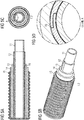
Figure 1 shows an apparatus for manufacturing apiping element 10, whereinFigure 2 shows the individual layers of thepiping element 10. Theinner pipes 11 are manufactured in advance and wound into coils. The apparatus thus comprises means 1 for feeding theinner pipes 11 from the coils. Theinner pipes 11 are fed through a windingdevice 3, in which a web ofVIP 12 fed frommeans 2 is wound around theinner pipes 11. In means 4, foil 16 is wound over the web of VIP. Because theinner pipes 11 move continuously forward in the apparatus, i.e. to the left inFigure 1 , and the winding device 4 winds the plastic film roll around theinner pipes 11, theplastic film 16 settles on the web of VIP around thepipes 11 in the form of a helical curve or spiral. Theplastic film 16 is wound tightly on the web ofVIP 12 and independently around at least one or more of theinner pipes 11 outside the web ofVIP 12 and inside of the one or more foamed insulation layers in the form of helical curve for preventing the longitudinal movement of each of the one or moreinner pipes 11 with respect to the web of ofVIP 12 and/or, wherein theinsulated pipe 10 comprises two or moreinner pipes 11, theplastic film 16 is wound around the two or moreinner pipes 11 outside the web ofVIP 12 and inside of the one or more foamed insulation layers 13, 14 in the form of helical curve thus arranging theplastic film 16 to surround the two or moreinner pipes 11 together for preventing the longitudinal movement of theinner pipes 11 with respect to each other. - The insulating layers 13, 14 are prefabricated insulators in a sheet-like form on a
coil 6. From thecoil 6, the insulatinglayers wrapping device 6, in which the insulatinglayers inner pipes 11. The sides of the insulatinglayers layers layers inner pipes 11. The welding device can also melt the seam closed in some other manner known per se than by utilizing hot air. Instead of the welding device, the sides of the insulatinglayers - In addition or alternatively to using a
plastic film 16, the web ofVIP 12 may be secured to theinner pipe 11. Preferably, this is made by using an adhesive (17) between theinner pipe 11 and the web of VIP (12) (please seeFigs. 2c and 2d ) or an adhesive (18, 19) between the longitudinal ends of the web of VIP (please seeFigs. 3c, 3d ,4c, and 4d ). It is also possible to use an adhesive tape (20), which can be, for example, applied above the seam outside of the web of VIP (please seeFigs. 5c and 5d ). - The
inner pipes 11 and the insulatinglayers die 8 of an extruder 7. The extruder 7 and die 8 extrude outside the insulatinglayers 13, 14 a plastic layer, from which the corrugatedouter jacket 15 is formed for theinsulated pipe 10 in thecorrugator 9. Thecorrugator 9 has two sets of moving chill moulds in a manner known per se. The structure and operation of the extruder 7, die 8 andcorrugator 9 are not described in more detail herein, because they are fully known to a person skilled in the art. - As shown in each of
Figs. 2a, 2b ,3a, 3b ,4a, 4b ,5a, and 5b , theinsulated pipe 10 has a corrugatedouter jacket 15. Inside theouter jacket 15, there are insulatinglayers layers inner pipe 11 and a web ofVIP 12. - The material of the
plastic film 16 can be low-density polyethylene PE-LD, for instance, and itsthickness 20 µm, for instance. The width of theplastic film 16 can then be 60 to 120 mm, for instance. - In the event of using more than one
inner pipe 11 for theinsulated pipe 10, theinner pipes 11 may be in the form of a spiral or a helical curve. This winding also in turn helps in that, when theinsulated pipe 10 is bent, theinner pipes 11 do not endeavour to move in relation to each other. When manufacturing the insulatedpipe 10, theinner pipes 11 can be wound with a separate winding device. Conducted tests show, however, that theinner pipes 11 try to some extent to wind in relation to each other even without any separate winding arrangement. It has been found that this type of self-winding provides a suitable winding in most cases. - The insulating layers 13, 14 may be made of PE, PEX, PP, PUR or aerogel. They are most preferably made of cross-linked closed-cell polyethylene foam. The insulating layers 13, 14 can be formed of one or several prefabricated insulating sheet layers. The thicknesses of the different layers can be the same. Naturally, the width of an outer layer must be greater than that of an inner layer.
- The corrugated
outer jacket 15 can be made of PE or PP. It is most preferably made of polyethylene PE. Most preferably, theinner pipes 11, insulatinglayers outer jacket 15 of theinsulated pipe 10 are all made of either cross-linked or conventional polyethylene. For instance, the handling of theinsulated pipe 10 during winding is then simple and easy. It is naturally also possible to use other materials. For instance, the insulatinglayers outer jacket 15 can also be made of polypropylene. - The
outer jacket 15 is preferably corrugated. This enhances the ring stiffness of theinsulated pipe 10, forinstance 8 to 12 kN/m2. Theinsulated pipe 10 is especially well suited for underground use. Possible applications are district heating networks and tap water systems, for instance. Due to the optional corrugation, the softness of the insulatinglayers insulated pipe 10 is bendable means that theinsulated pipe 10 can be coiled for storage and transport and uncoiled for installation. The outer diameter of theinsulated pipe 10 can typically be 100 to 300 mm.Piping elements 1 of this kind can be coiled for storage and transport into a coil with a diameter of 0.8 to 3 m, for instance. - The drawing and the related description are intended only to illustrate the idea of the invention. The invention may vary in detail within the scope of the claims. Thus, most preferably, the insulating layer is formed of a prefabricated insulating sheet. The insulator can, however, also be made of a material that is prefabricated into a tube, in which case the tube has a longitudinal slot, through which the longitudinal components, such as
inner pipes 11, are installed inside the insulating tube. - The present application further relates to the following items:
- Item 1: An insulated pipe (10) comprising:
- one or more inner pipes (11) comprising a plastic
- a flexible vacuum insulation panel in the form of units forming a web (12) wrapped around at least one of the one or more inner pipes (11)
- one or more insulation layers (13; 14)
- an outer jacket (15).
- Item 2: The insulated pipe according to one of
item 1, wherein the insulated pipe (10) comprises two or more inner pipes (11). - Item 3: The insulated pipe according to
item 2, wherein each inner pipe (11) is surrounded by one web of vacuum insulation panels (12). - Item 4: The insulated pipe according to
item 2, wherein only one of the inner pipes (11) is surrounded by one web of vacuum insulation panels (12). - Item 5: The insulated pipe according to one of the preceding items, wherein the longitudinal ends of each of the one or more webs of vacuum insulation panels (12) are secured together, preferably by using a method selected from the group consisting of sewing, gluing, laminating, taping, and a combination thereof.
- Item 6: The insulated pipe according to one of the preceding items, wherein an adhesive (17, 18, 19) or adhesive tape (20) is arranged over at least the seam part of one side of the web of vacuum insulation panels (12) and the the surface of the inner pipe (11) and the web of vacuum insulation panels (12) are joined together by using the (17, 18, 19) or adhesive tape (20).
- Item 7: The insulated pipe according to one of the preceding items, further comprising a fastening means made up of plastic film (16) that is wound independently around at least one inner pipe (11) outside the web of flexible vacuum insulation panels (12) and inside of the one or more insulation layers (13, 14) in the form of helical curve for preventing the longitudinal movement of each of the one or more inner pipes (11) with respect to the web of of vacuum insulation panels (12).
- Item 8: The insulated pipe according to one of the preceding items, wherein the insulated pipe (10) comprises two or more inner pipes and further comprises a fastening means made up of plastic film (16) that is wound around the two or more inner pipes (11) outside the web of flexible vacuum insulation panels (12) and inside of the one or more insulation layers (13, 14) in the form of helical curve and arranged to surround both of the inner pipes together for preventing the longitudinal movement of the inner pipes (11) with respect to each other.
- Item 9: A method for manufacturing an insulated pipe according to any one of items 1 to 8, comprising winding plastic film (16), thus producing a fastening means made up of plastic film (16), independently around at least one inner pipe (11) outside the web of flexible vacuum insulation panels (12) and inside of the one or more insulation layers (13, 14) in the form of helical curve for preventing the longitudinal movement of each of the one or more inner pipes with respect to the web of of vacuum insulation panels (12) and/or, wherein the insulated pipe comprises two or more inner pipes (11), winding plastic film (16), thus producing a fastening means made up of plastic film (16), around two or more inner pipes (11) outside the web of flexible vacuum insulation panels (12) and inside of the one or more insulation layers (13, 14) in the form of helical curve and arranging plastic film (16) to surround two or more of the inner pipes (11) together for preventing the longitudinal movement of the inner pipes with respect to each other, arranging insulation layers (13, 14) outside the plastic film (16) beneath the outer jacket (15), and forming an outer jacket (15) outside the insulation layers (13, 14).
- Item 10: A method as defined in
item 9, characterized by forming the one or more insulation layers (13, 14) beneath the outer jacket (15) by wrapping an insulation sheet around the one or more inner pipes (11). - Item 11: An apparatus for manufacturing insulated pipe (10), the apparatus comprising means for feeding longitudinal components, whereby at least one of the longitudinal components is an inner pipe (11) and one of the longitudinal components is a web of of flexible vacuum insulation panels (12), which is arranged around one or more of the at least one inner pipe (11), means (6) for arranging one or more foamed insulation layers (13, 14) outside the longitudinal components, an extruder (7) and a corrugator (9) for forming an outer jacket (15) outside the one or more insulation layers (13, 14), and means (5) for arranging fastening means made up of plastic film (16) in the form of helical curve to the longitudinal components to touch each of the longitudinal components in such a manner that the fastening means prevent the longitudinal movement of the longitudinal components with respect to each other.
- Item 12: An apparatus as defined in
item 11, characterized in that the apparatus comprises a winding device (5) for winding plastic film (16) in the form of a helical curve independently around at least one inner pipe (11) outside the web of flexible vacuum insulation panels (12) and inside of the one or more foamed insulation layers (13, 14) in the form of helical curve for preventing the longitudinal movement of each of the one or more inner pipes (11) with respect to the web of of flexible vacuum insulation panels (12) and/or, wherein the insulated pipe (10) comprises two or more inner pipes (11), winding plastic film (16), thus producing a fastening means made up of plastic film (16) around two or more inner pipes (11) outside the web of flexible vacuum insulation panels (12) and inside of the one or more foamed insulation layers (13, 14) in the form of helical curve and arranging plastic film (16) to surround two or more of the inner pipes (11) together for preventing the longitudinal movement of the inner pipes (11) with respect to each other. Item 13: An apparatus as defined initem - Item 14: An apparatus as defined in
item 13, characterized in that the apparatus comprises a wrapping device (6) for wrapping a prefabricated insulation layers (13, 14) around the one or more inner pipes (11). -
- 1
- Inner pipe is fed to the line
- 2
- Web of VIP is fed to the line
- 3
- Web of VIP is wound over the inner pipe
- 4
- The longitudinal ends of the web of VIP are secured together
- 5
- Foil is wound over the web of VIP
- 6
- Insulation layers are fed to the line
- 7
- Extruder plastifies material for outer jacket
- 8
- Die extrudes outer layer
- 9
- Corrugator creates the form of outer layer
- 10
- Insulated pipe
- 11
- Inner pipe
- 12
- Web of VIP
- 13, 14
- Insulation layers
- 15
- Outer jacket
- 16
- Foil
- 17, 18, 19
- Adhesive
- 20
- Adhesive tape
Claims (14)
- An insulated pipe (10) comprising:- one or more inner pipes (11) comprising a plastic- a flexible vacuum insulation panel in the form of units joined to each other (12) wrapped around at least one of the one or more inner pipes (11)- one or more insulation layers (13; 14)- an outer jacket (15).
- The insulated pipe according to one of claim 1, wherein the insulated pipe (10) comprises two or more inner pipes (11) .
- The insulated pipe according to claim 2, wherein each inner pipe (11) is surrounded by vacuum insulation panels (12) .
- The insulated pipe according to claim 2, wherein only one of the inner pipes (11) is surrounded by vacuum insulation panels (12).
- The insulated pipe according to one of the preceding claims, wherein the longitudinal ends of each of the one or more vacuum insulation panels (12) are secured together, preferably by using a method selected from the group consisting of sewing, gluing, laminating, taping, and a combination thereof.
- The insulated pipe according to one of the preceding claims, wherein an adhesive (17, 18, 19) or adhesive tape (20) is arranged over at least the seam part of one side of vacuum insulation panels (12) and the the surface of the inner pipe (11) and vacuum insulation panels (12) are joined together by using the adhesive (17, 18, 19) or adhesive tape (20) .
- The insulated pipe according to one of the preceding claims, further comprising a fastening means made up of plastic film (16) that is wound independently around at least one inner pipe (11) outside the flexible vacuum insulation panels (12) and inside of the one or more insulation layers (13, 14) in the form of helical curve for preventing the longitudinal movement of each of the one or more inner pipes (11) with respect to the vacuum insulation panels (12).
- The insulated pipe according to one of the preceding claims, wherein the insulated pipe (10) comprises two or more inner pipes and further comprises a fastening means made up of plastic film (16) that is wound around the two or more inner pipes (11) outside the flexible vacuum insulation panels (12) and inside of the one or more insulation layers (13, 14) in the form of helical curve and arranged to surround both of the inner pipes together for preventing the longitudinal movement of the inner pipes (11) with respect to each other.
- A method for manufacturing an insulated pipe according to any one of claims 1 to 8, comprising winding plastic film (16), thus producing a fastening means made up of plastic film (16), independently around at least one inner pipe (11) outside the flexible vacuum insulation panels (12) and inside of the one or more insulation layers (13, 14) in the form of helical curve for preventing the longitudinal movement of each of the one or more inner pipes with respect to the of vacuum insulation panels (12) and/or, wherein the insulated pipe comprises two or more inner pipes (11), winding plastic film (16), thus producing a fastening means made up of plastic film (16), around two or more inner pipes (11) outside the flexible vacuum insulation panels (12) and inside of the one or more insulation layers (13, 14) in the form of helical curve and arranging plastic film (16) to surround two or more of the inner pipes (11) together for preventing the longitudinal movement of the inner pipes with respect to each other, arranging insulation layers (13, 14) outside the plastic film (16) beneath the outer jacket (15), and forming an outer jacket (15) outside the insulation layers (13, 14).
- A method as claimed in claim 9, characterized by forming the one or more insulation layers (13, 14) beneath the outer jacket (15) by wrapping an insulation sheet around the one or more inner pipes (11).
- An apparatus for manufacturing insulated pipe (10), the apparatus comprising means for feeding longitudinal components, whereby at least one of the longitudinal components is an inner pipe (11) and one of the longitudinal components is a of flexible vacuum insulation panels (12), which is arranged around one or more of the at least one inner pipe (11), means (6) for arranging one or more foamed insulation layers (13, 14) outside the longitudinal components, an extruder (7) and a corrugator (9) for forming an outer jacket (15) outside the one or more insulation layers (13, 14), and means (5) for arranging fastening means made up of plastic film (16) in the form of helical curve to the longitudinal components to touch each of the longitudinal components in such a manner that the fastening means prevent the longitudinal movement of the longitudinal components with respect to each other.
- An apparatus as claimed in claim 11, characterized in that the apparatus comprises a winding device (5) for winding plastic film (16) in the form of a helical curve independently around at least one inner pipe (11) outside the flexible vacuum insulation panels (12) and inside of the one or more foamed insulation layers (13, 14) in the form of helical curve for preventing the longitudinal movement of each of the one or more inner pipes (11) with respect to the flexible vacuum insulation panels (12) and/or, wherein the insulated pipe (10) comprises two or more inner pipes (11), winding plastic film (16), thus producing a fastening means made up of plastic film (16) around two or more inner pipes (11) outside the flexible vacuum insulation panels (12) and inside of the one or more foamed insulation layers (13, 14) in the form of helical curve and arranging plastic film (16) to surround two or more of the inner pipes (11) together for preventing the longitudinal movement of the inner pipes (11) with respect to each other.
- An apparatus as claimed in claim 11 or 12, characterized in that the apparatus comprises means (6) for arranging a prefabricated insulation layers (13, 14) around the longitudinal components.
- An apparatus as claimed in claim 13, characterized in that the apparatus comprises a wrapping device (6) for wrapping a prefabricated insulation layers (13, 14) around the one or more inner pipes (11).
Applications Claiming Priority (1)
| Application Number | Priority Date | Filing Date | Title |
|---|---|---|---|
| DE102019104585 | 2019-02-22 |
Publications (2)
| Publication Number | Publication Date |
|---|---|
| EP3699470A1 true EP3699470A1 (en) | 2020-08-26 |
| EP3699470B1 EP3699470B1 (en) | 2022-11-09 |
Family
ID=69326404
Family Applications (1)
| Application Number | Title | Priority Date | Filing Date |
|---|---|---|---|
| EP20153846.9A Active EP3699470B1 (en) | 2019-02-22 | 2020-01-27 | Insulated pipe |
Country Status (8)
| Country | Link |
|---|---|
| US (1) | US11181223B2 (en) |
| EP (1) | EP3699470B1 (en) |
| CA (1) | CA3072938C (en) |
| DK (1) | DK3699470T3 (en) |
| ES (1) | ES2937065T3 (en) |
| FI (1) | FI3699470T3 (en) |
| PL (1) | PL3699470T3 (en) |
| PT (1) | PT3699470T (en) |
Cited By (3)
| Publication number | Priority date | Publication date | Assignee | Title |
|---|---|---|---|---|
| CN112828196A (en) * | 2020-12-22 | 2021-05-25 | 大连理工大学 | A vacuum flexible cryogenic hose and its preparation method and application |
| EP4143475A1 (en) * | 2020-04-30 | 2023-03-08 | R. Van Den Hanenberg B.V. | Improved method for applying insulation material |
| EP4589187A1 (en) * | 2024-01-18 | 2025-07-23 | Thermaflex International Holding B.V. | Insulated pipe |
Families Citing this family (7)
| Publication number | Priority date | Publication date | Assignee | Title |
|---|---|---|---|---|
| US11828404B2 (en) * | 2021-08-09 | 2023-11-28 | PTubes, Inc. | Pipe for conveying fluids in HVACR systems |
| CN120693480A (en) * | 2023-02-28 | 2025-09-23 | 尤波诺尔创新公司 | Isolate pipelines |
| EP4509746A1 (en) * | 2023-08-15 | 2025-02-19 | Aborra AG | Multilayer pipeline, its use and method of laying such pipeline |
| DE102023136201A1 (en) * | 2023-12-21 | 2025-06-26 | REHAU Industries SE & Co. KG | Thermally insulated pipe arrangement |
| DE102023136175A1 (en) * | 2023-12-21 | 2025-06-26 | REHAU Industries SE & Co. KG | Multi-layer corrugated pipe outer jacket and this comprehensive pipe arrangement |
| EP4613944A1 (en) * | 2024-03-08 | 2025-09-10 | Uponor Innovation AB | Distribution device for plumbing and a plumbing system for distributing hot and cold fluid |
| EP4632261A1 (en) * | 2024-04-08 | 2025-10-15 | Uponor Innovation AB | Riser system for providing heat and water in buildings |
Citations (6)
| Publication number | Priority date | Publication date | Assignee | Title |
|---|---|---|---|---|
| WO1995000797A1 (en) | 1993-06-24 | 1995-01-05 | Fjärrvärmeutveckling Fvu Ab | Insulated pipe |
| WO2003068481A1 (en) * | 2002-02-12 | 2003-08-21 | Uponor Innovation Ab | Piping element and manufacturing method and apparatus |
| WO2014183814A1 (en) | 2013-05-15 | 2014-11-20 | Va-Q-Tec Ag | Method for producing a vacuum insulating body |
| WO2017144609A1 (en) | 2016-02-26 | 2017-08-31 | Uponor Innovation Ab | Insulated pipe |
| EP3354959A1 (en) * | 2017-01-31 | 2018-08-01 | Powerpipe Systems AB | Improved pipe insulation |
| EP3354559A1 (en) | 2017-01-26 | 2018-08-01 | AIRBUS HELICOPTERS DEUTSCHLAND GmbH | A thrust producing unit with at least two rotor assemblies and a shrouding |
Family Cites Families (11)
| Publication number | Priority date | Publication date | Assignee | Title |
|---|---|---|---|---|
| US4194536A (en) * | 1976-12-09 | 1980-03-25 | Eaton Corporation | Composite tubing product |
| US5142842A (en) * | 1989-12-13 | 1992-09-01 | W. R. Grace & Co.-Conn. | Method for making a film/foil panel |
| US5950450A (en) * | 1996-06-12 | 1999-09-14 | Vacupanel, Inc. | Containment system for transporting and storing temperature-sensitive materials |
| IT1318100B1 (en) * | 2000-06-30 | 2003-07-23 | Getters Spa | EVACUATED PANEL FOR THERMAL INSULATION OF A BODY WITH A NON-FLAT SURFACE |
| ITMI20011458A1 (en) * | 2001-07-09 | 2003-01-09 | Getters Spa | SYSTEM FOR THE THERMAL INSULATION OF TUBULAR BODIES |
| DE102005045726A1 (en) | 2005-09-23 | 2007-04-05 | Va-Q-Tec Ag | Process for producing a film-wrapped vacuum insulation body |
| FI125098B (en) * | 2007-05-23 | 2015-05-29 | Uponor Innovation Ab | A piping element and a method and apparatus for making it |
| WO2014122278A1 (en) * | 2013-02-08 | 2014-08-14 | Logstor A/S | Method for producing an insulated pipe in corrugated casing |
| EP2873901B1 (en) * | 2013-11-15 | 2018-01-03 | Nexans | Flexible conduit |
| GB2534185B (en) * | 2015-01-15 | 2017-03-29 | Kingspan Holdings (Irl) Ltd | Vacuum insulating panel |
| CA3148632C (en) * | 2015-11-12 | 2023-02-07 | Owens Corning Intellectual Capital, Llc | Pipe insulation assembly |
-
2020
- 2020-01-27 EP EP20153846.9A patent/EP3699470B1/en active Active
- 2020-01-27 ES ES20153846T patent/ES2937065T3/en active Active
- 2020-01-27 PL PL20153846.9T patent/PL3699470T3/en unknown
- 2020-01-27 PT PT201538469T patent/PT3699470T/en unknown
- 2020-01-27 DK DK20153846.9T patent/DK3699470T3/en active
- 2020-01-27 FI FIEP20153846.9T patent/FI3699470T3/en active
- 2020-02-18 CA CA3072938A patent/CA3072938C/en active Active
- 2020-02-21 US US16/798,209 patent/US11181223B2/en active Active
Patent Citations (6)
| Publication number | Priority date | Publication date | Assignee | Title |
|---|---|---|---|---|
| WO1995000797A1 (en) | 1993-06-24 | 1995-01-05 | Fjärrvärmeutveckling Fvu Ab | Insulated pipe |
| WO2003068481A1 (en) * | 2002-02-12 | 2003-08-21 | Uponor Innovation Ab | Piping element and manufacturing method and apparatus |
| WO2014183814A1 (en) | 2013-05-15 | 2014-11-20 | Va-Q-Tec Ag | Method for producing a vacuum insulating body |
| WO2017144609A1 (en) | 2016-02-26 | 2017-08-31 | Uponor Innovation Ab | Insulated pipe |
| EP3354559A1 (en) | 2017-01-26 | 2018-08-01 | AIRBUS HELICOPTERS DEUTSCHLAND GmbH | A thrust producing unit with at least two rotor assemblies and a shrouding |
| EP3354959A1 (en) * | 2017-01-31 | 2018-08-01 | Powerpipe Systems AB | Improved pipe insulation |
Cited By (4)
| Publication number | Priority date | Publication date | Assignee | Title |
|---|---|---|---|---|
| EP4143475A1 (en) * | 2020-04-30 | 2023-03-08 | R. Van Den Hanenberg B.V. | Improved method for applying insulation material |
| CN112828196A (en) * | 2020-12-22 | 2021-05-25 | 大连理工大学 | A vacuum flexible cryogenic hose and its preparation method and application |
| EP4589187A1 (en) * | 2024-01-18 | 2025-07-23 | Thermaflex International Holding B.V. | Insulated pipe |
| NL2036830B1 (en) * | 2024-01-18 | 2025-07-28 | Thermaflex Int Holding B V | Insulated pipe |
Also Published As
| Publication number | Publication date |
|---|---|
| PL3699470T3 (en) | 2023-05-08 |
| PT3699470T (en) | 2023-01-10 |
| US20200271264A1 (en) | 2020-08-27 |
| US11181223B2 (en) | 2021-11-23 |
| FI3699470T3 (en) | 2023-02-28 |
| ES2937065T3 (en) | 2023-03-23 |
| CA3072938A1 (en) | 2020-08-22 |
| DK3699470T3 (en) | 2023-01-30 |
| EP3699470B1 (en) | 2022-11-09 |
| CA3072938C (en) | 2025-09-02 |
Similar Documents
| Publication | Publication Date | Title |
|---|---|---|
| EP3699470B1 (en) | Insulated pipe | |
| US20250060066A1 (en) | Insulated pipe | |
| KR101333475B1 (en) | Heat-insulated pipe | |
| FI73806C (en) | Plastic pipe with an oxygen impervious jacket | |
| FI125098B (en) | A piping element and a method and apparatus for making it | |
| CA1225043A (en) | Thermally insulated conduction of fluid | |
| US20220252205A1 (en) | Insulated pipe | |
| EP1483099B1 (en) | Piping element and manufacturing method and apparatus | |
| KR101105517B1 (en) | Insulated conduit | |
| GB2111164A (en) | Method of producing a composite pipe | |
| EP4673678A1 (en) | Insulated pipe | |
| DE202019004158U1 (en) | Insulated pipe | |
| EP4269855B1 (en) | Thermally insulated conduit | |
| EP4632261A1 (en) | Riser system for providing heat and water in buildings | |
| HUP0003237A2 (en) | Pipe shell insulating pipe, arrangments for insulating pipes and method for manufacturing pipe shell | |
| JP6523022B2 (en) | Heat and earthquake resistant piping system | |
| ITBG20130013A1 (en) | THERMAL INSULATED PIPE FOR FLUID TRANSPORT | |
| CN221004135U (en) | Coiled armoured pipeline | |
| RU81791U1 (en) | HEATED PIPE FOR HEATING AND / OR WATER SUPPLY SYSTEMS FOR BUILDINGS AND STRUCTURES | |
| EP2816274A1 (en) | Preinsulated pipe jacket and a method for manufacturing the preinsulated pipe jacket | |
| AU2006202669A1 (en) | A heavy plastic film, insulating structures containing it, process for its preparation and the use thereof | |
| HK1082266A (en) | A heavy plastic film, insulating structures containing it, process for its preparation and the use thereof | |
| JPH0289887A (en) | Combined heat and electricity transport pipes for cogeneration systems |
Legal Events
| Date | Code | Title | Description |
|---|---|---|---|
| PUAI | Public reference made under article 153(3) epc to a published international application that has entered the european phase |
Free format text: ORIGINAL CODE: 0009012 |
|
| STAA | Information on the status of an ep patent application or granted ep patent |
Free format text: STATUS: THE APPLICATION HAS BEEN PUBLISHED |
|
| AK | Designated contracting states |
Kind code of ref document: A1 Designated state(s): AL AT BE BG CH CY CZ DE DK EE ES FI FR GB GR HR HU IE IS IT LI LT LU LV MC MK MT NL NO PL PT RO RS SE SI SK SM TR |
|
| AX | Request for extension of the european patent |
Extension state: BA ME |
|
| STAA | Information on the status of an ep patent application or granted ep patent |
Free format text: STATUS: REQUEST FOR EXAMINATION WAS MADE |
|
| 17P | Request for examination filed |
Effective date: 20210222 |
|
| RBV | Designated contracting states (corrected) |
Designated state(s): AL AT BE BG CH CY CZ DE DK EE ES FI FR GB GR HR HU IE IS IT LI LT LU LV MC MK MT NL NO PL PT RO RS SE SI SK SM TR |
|
| GRAP | Despatch of communication of intention to grant a patent |
Free format text: ORIGINAL CODE: EPIDOSNIGR1 |
|
| STAA | Information on the status of an ep patent application or granted ep patent |
Free format text: STATUS: GRANT OF PATENT IS INTENDED |
|
| INTG | Intention to grant announced |
Effective date: 20220704 |
|
| GRAS | Grant fee paid |
Free format text: ORIGINAL CODE: EPIDOSNIGR3 |
|
| GRAA | (expected) grant |
Free format text: ORIGINAL CODE: 0009210 |
|
| STAA | Information on the status of an ep patent application or granted ep patent |
Free format text: STATUS: THE PATENT HAS BEEN GRANTED |
|
| AK | Designated contracting states |
Kind code of ref document: B1 Designated state(s): AL AT BE BG CH CY CZ DE DK EE ES FI FR GB GR HR HU IE IS IT LI LT LU LV MC MK MT NL NO PL PT RO RS SE SI SK SM TR |
|
| REG | Reference to a national code |
Ref country code: GB Ref legal event code: FG4D |
|
| REG | Reference to a national code |
Ref country code: CH Ref legal event code: EP Ref country code: AT Ref legal event code: REF Ref document number: 1530570 Country of ref document: AT Kind code of ref document: T Effective date: 20221115 |
|
| REG | Reference to a national code |
Ref country code: DE Ref legal event code: R096 Ref document number: 602020006101 Country of ref document: DE |
|
| REG | Reference to a national code |
Ref country code: IE Ref legal event code: FG4D |
|
| REG | Reference to a national code |
Ref country code: PT Ref legal event code: SC4A Ref document number: 3699470 Country of ref document: PT Date of ref document: 20230110 Kind code of ref document: T Free format text: AVAILABILITY OF NATIONAL TRANSLATION Effective date: 20230103 |
|
| REG | Reference to a national code |
Ref country code: NL Ref legal event code: FP |
|
| REG | Reference to a national code |
Ref country code: DK Ref legal event code: T3 Effective date: 20230123 |
|
| REG | Reference to a national code |
Ref country code: SE Ref legal event code: TRGR |
|
| REG | Reference to a national code |
Ref country code: SK Ref legal event code: T3 Ref document number: E 41050 Country of ref document: SK |
|
| REG | Reference to a national code |
Ref country code: LT Ref legal event code: MG9D |
|
| REG | Reference to a national code |
Ref country code: NO Ref legal event code: T2 Effective date: 20221109 |
|
| REG | Reference to a national code |
Ref country code: ES Ref legal event code: FG2A Ref document number: 2937065 Country of ref document: ES Kind code of ref document: T3 Effective date: 20230323 |
|
| REG | Reference to a national code |
Ref country code: AT Ref legal event code: MK05 Ref document number: 1530570 Country of ref document: AT Kind code of ref document: T Effective date: 20221109 |
|
| PG25 | Lapsed in a contracting state [announced via postgrant information from national office to epo] |
Ref country code: LT Free format text: LAPSE BECAUSE OF FAILURE TO SUBMIT A TRANSLATION OF THE DESCRIPTION OR TO PAY THE FEE WITHIN THE PRESCRIBED TIME-LIMIT Effective date: 20221109 Ref country code: AT Free format text: LAPSE BECAUSE OF FAILURE TO SUBMIT A TRANSLATION OF THE DESCRIPTION OR TO PAY THE FEE WITHIN THE PRESCRIBED TIME-LIMIT Effective date: 20221109 |
|
| PG25 | Lapsed in a contracting state [announced via postgrant information from national office to epo] |
Ref country code: RS Free format text: LAPSE BECAUSE OF FAILURE TO SUBMIT A TRANSLATION OF THE DESCRIPTION OR TO PAY THE FEE WITHIN THE PRESCRIBED TIME-LIMIT Effective date: 20221109 Ref country code: LV Free format text: LAPSE BECAUSE OF FAILURE TO SUBMIT A TRANSLATION OF THE DESCRIPTION OR TO PAY THE FEE WITHIN THE PRESCRIBED TIME-LIMIT Effective date: 20221109 Ref country code: IS Free format text: LAPSE BECAUSE OF FAILURE TO SUBMIT A TRANSLATION OF THE DESCRIPTION OR TO PAY THE FEE WITHIN THE PRESCRIBED TIME-LIMIT Effective date: 20230309 Ref country code: HR Free format text: LAPSE BECAUSE OF FAILURE TO SUBMIT A TRANSLATION OF THE DESCRIPTION OR TO PAY THE FEE WITHIN THE PRESCRIBED TIME-LIMIT Effective date: 20221109 Ref country code: GR Free format text: LAPSE BECAUSE OF FAILURE TO SUBMIT A TRANSLATION OF THE DESCRIPTION OR TO PAY THE FEE WITHIN THE PRESCRIBED TIME-LIMIT Effective date: 20230210 |
|
| PG25 | Lapsed in a contracting state [announced via postgrant information from national office to epo] |
Ref country code: SM Free format text: LAPSE BECAUSE OF FAILURE TO SUBMIT A TRANSLATION OF THE DESCRIPTION OR TO PAY THE FEE WITHIN THE PRESCRIBED TIME-LIMIT Effective date: 20221109 Ref country code: RO Free format text: LAPSE BECAUSE OF FAILURE TO SUBMIT A TRANSLATION OF THE DESCRIPTION OR TO PAY THE FEE WITHIN THE PRESCRIBED TIME-LIMIT Effective date: 20221109 Ref country code: EE Free format text: LAPSE BECAUSE OF FAILURE TO SUBMIT A TRANSLATION OF THE DESCRIPTION OR TO PAY THE FEE WITHIN THE PRESCRIBED TIME-LIMIT Effective date: 20221109 |
|
| REG | Reference to a national code |
Ref country code: DE Ref legal event code: R097 Ref document number: 602020006101 Country of ref document: DE |
|
| PG25 | Lapsed in a contracting state [announced via postgrant information from national office to epo] |
Ref country code: AL Free format text: LAPSE BECAUSE OF FAILURE TO SUBMIT A TRANSLATION OF THE DESCRIPTION OR TO PAY THE FEE WITHIN THE PRESCRIBED TIME-LIMIT Effective date: 20221109 |
|
| PLBE | No opposition filed within time limit |
Free format text: ORIGINAL CODE: 0009261 |
|
| STAA | Information on the status of an ep patent application or granted ep patent |
Free format text: STATUS: NO OPPOSITION FILED WITHIN TIME LIMIT |
|
| PG25 | Lapsed in a contracting state [announced via postgrant information from national office to epo] |
Ref country code: LU Free format text: LAPSE BECAUSE OF NON-PAYMENT OF DUE FEES Effective date: 20230127 |
|
| 26N | No opposition filed |
Effective date: 20230810 |
|
| PG25 | Lapsed in a contracting state [announced via postgrant information from national office to epo] |
Ref country code: SI Free format text: LAPSE BECAUSE OF FAILURE TO SUBMIT A TRANSLATION OF THE DESCRIPTION OR TO PAY THE FEE WITHIN THE PRESCRIBED TIME-LIMIT Effective date: 20221109 |
|
| PG25 | Lapsed in a contracting state [announced via postgrant information from national office to epo] |
Ref country code: IE Free format text: LAPSE BECAUSE OF NON-PAYMENT OF DUE FEES Effective date: 20230127 |
|
| PG25 | Lapsed in a contracting state [announced via postgrant information from national office to epo] |
Ref country code: MC Free format text: LAPSE BECAUSE OF FAILURE TO SUBMIT A TRANSLATION OF THE DESCRIPTION OR TO PAY THE FEE WITHIN THE PRESCRIBED TIME-LIMIT Effective date: 20221109 |
|
| PG25 | Lapsed in a contracting state [announced via postgrant information from national office to epo] |
Ref country code: MC Free format text: LAPSE BECAUSE OF FAILURE TO SUBMIT A TRANSLATION OF THE DESCRIPTION OR TO PAY THE FEE WITHIN THE PRESCRIBED TIME-LIMIT Effective date: 20221109 |
|
| PG25 | Lapsed in a contracting state [announced via postgrant information from national office to epo] |
Ref country code: BG Free format text: LAPSE BECAUSE OF FAILURE TO SUBMIT A TRANSLATION OF THE DESCRIPTION OR TO PAY THE FEE WITHIN THE PRESCRIBED TIME-LIMIT Effective date: 20221109 |
|
| PG25 | Lapsed in a contracting state [announced via postgrant information from national office to epo] |
Ref country code: BG Free format text: LAPSE BECAUSE OF FAILURE TO SUBMIT A TRANSLATION OF THE DESCRIPTION OR TO PAY THE FEE WITHIN THE PRESCRIBED TIME-LIMIT Effective date: 20221109 |
|
| PG25 | Lapsed in a contracting state [announced via postgrant information from national office to epo] |
Ref country code: CY Free format text: LAPSE BECAUSE OF FAILURE TO SUBMIT A TRANSLATION OF THE DESCRIPTION OR TO PAY THE FEE WITHIN THE PRESCRIBED TIME-LIMIT; INVALID AB INITIO Effective date: 20200127 |
|
| PG25 | Lapsed in a contracting state [announced via postgrant information from national office to epo] |
Ref country code: HU Free format text: LAPSE BECAUSE OF FAILURE TO SUBMIT A TRANSLATION OF THE DESCRIPTION OR TO PAY THE FEE WITHIN THE PRESCRIBED TIME-LIMIT; INVALID AB INITIO Effective date: 20200127 |
|
| REG | Reference to a national code |
Ref country code: CH Ref legal event code: U11 Free format text: ST27 STATUS EVENT CODE: U-0-0-U10-U11 (AS PROVIDED BY THE NATIONAL OFFICE) Effective date: 20260201 |
|
| PGFP | Annual fee paid to national office [announced via postgrant information from national office to epo] |
Ref country code: NL Payment date: 20260121 Year of fee payment: 7 |
|
| PGFP | Annual fee paid to national office [announced via postgrant information from national office to epo] |
Ref country code: SE Payment date: 20260121 Year of fee payment: 7 |
|
| PGFP | Annual fee paid to national office [announced via postgrant information from national office to epo] |
Ref country code: GB Payment date: 20260123 Year of fee payment: 7 |
|
| PGFP | Annual fee paid to national office [announced via postgrant information from national office to epo] |
Ref country code: ES Payment date: 20260227 Year of fee payment: 7 |
|
| PGFP | Annual fee paid to national office [announced via postgrant information from national office to epo] |
Ref country code: DK Payment date: 20260126 Year of fee payment: 7 Ref country code: NO Payment date: 20260123 Year of fee payment: 7 Ref country code: DE Payment date: 20260121 Year of fee payment: 7 |
|
| PGFP | Annual fee paid to national office [announced via postgrant information from national office to epo] |
Ref country code: BE Payment date: 20260121 Year of fee payment: 7 Ref country code: FI Payment date: 20260129 Year of fee payment: 7 Ref country code: IT Payment date: 20260122 Year of fee payment: 7 |
|
| PGFP | Annual fee paid to national office [announced via postgrant information from national office to epo] |
Ref country code: FR Payment date: 20260123 Year of fee payment: 7 |
|
| PGFP | Annual fee paid to national office [announced via postgrant information from national office to epo] |
Ref country code: TR Payment date: 20260122 Year of fee payment: 7 |
|
| PGFP | Annual fee paid to national office [announced via postgrant information from national office to epo] |
Ref country code: PT Payment date: 20260115 Year of fee payment: 7 Ref country code: CH Payment date: 20260201 Year of fee payment: 7 Ref country code: CZ Payment date: 20260120 Year of fee payment: 7 |
|
| PGFP | Annual fee paid to national office [announced via postgrant information from national office to epo] |
Ref country code: PL Payment date: 20260115 Year of fee payment: 7 |
|
| PGFP | Annual fee paid to national office [announced via postgrant information from national office to epo] |
Ref country code: SK Payment date: 20260123 Year of fee payment: 7 |