EP3699399A1 - Schaufel für eine schnelllaufende turbinenstufe mit einzelnem dichtelement - Google Patents
Schaufel für eine schnelllaufende turbinenstufe mit einzelnem dichtelement Download PDFInfo
- Publication number
- EP3699399A1 EP3699399A1 EP20158370.5A EP20158370A EP3699399A1 EP 3699399 A1 EP3699399 A1 EP 3699399A1 EP 20158370 A EP20158370 A EP 20158370A EP 3699399 A1 EP3699399 A1 EP 3699399A1
- Authority
- EP
- European Patent Office
- Prior art keywords
- blade
- shroud
- turbine stage
- turbine
- chord length
- Prior art date
- Legal status (The legal status is an assumption and is not a legal conclusion. Google has not performed a legal analysis and makes no representation as to the accuracy of the status listed.)
- Granted
Links
Images
Classifications
-
- F—MECHANICAL ENGINEERING; LIGHTING; HEATING; WEAPONS; BLASTING
- F01—MACHINES OR ENGINES IN GENERAL; ENGINE PLANTS IN GENERAL; STEAM ENGINES
- F01D—NON-POSITIVE DISPLACEMENT MACHINES OR ENGINES, e.g. STEAM TURBINES
- F01D5/00—Blades; Blade-carrying members; Heating, heat-insulating, cooling or antivibration means on the blades or the members
- F01D5/12—Blades
- F01D5/22—Blade-to-blade connections, e.g. for damping vibrations
- F01D5/225—Blade-to-blade connections, e.g. for damping vibrations by shrouding
-
- F—MECHANICAL ENGINEERING; LIGHTING; HEATING; WEAPONS; BLASTING
- F01—MACHINES OR ENGINES IN GENERAL; ENGINE PLANTS IN GENERAL; STEAM ENGINES
- F01D—NON-POSITIVE DISPLACEMENT MACHINES OR ENGINES, e.g. STEAM TURBINES
- F01D5/00—Blades; Blade-carrying members; Heating, heat-insulating, cooling or antivibration means on the blades or the members
- F01D5/12—Blades
- F01D5/28—Selecting particular materials; Particular measures relating thereto; Measures against erosion or corrosion
- F01D5/284—Selection of ceramic materials
-
- F—MECHANICAL ENGINEERING; LIGHTING; HEATING; WEAPONS; BLASTING
- F01—MACHINES OR ENGINES IN GENERAL; ENGINE PLANTS IN GENERAL; STEAM ENGINES
- F01D—NON-POSITIVE DISPLACEMENT MACHINES OR ENGINES, e.g. STEAM TURBINES
- F01D5/00—Blades; Blade-carrying members; Heating, heat-insulating, cooling or antivibration means on the blades or the members
- F01D5/12—Blades
- F01D5/14—Form or construction
- F01D5/141—Shape, i.e. outer, aerodynamic form
- F01D5/142—Shape, i.e. outer, aerodynamic form of the blades of successive rotor or stator blade-rows
-
- F—MECHANICAL ENGINEERING; LIGHTING; HEATING; WEAPONS; BLASTING
- F01—MACHINES OR ENGINES IN GENERAL; ENGINE PLANTS IN GENERAL; STEAM ENGINES
- F01D—NON-POSITIVE DISPLACEMENT MACHINES OR ENGINES, e.g. STEAM TURBINES
- F01D5/00—Blades; Blade-carrying members; Heating, heat-insulating, cooling or antivibration means on the blades or the members
- F01D5/12—Blades
- F01D5/28—Selecting particular materials; Particular measures relating thereto; Measures against erosion or corrosion
- F01D5/288—Protective coatings for blades
-
- F—MECHANICAL ENGINEERING; LIGHTING; HEATING; WEAPONS; BLASTING
- F01—MACHINES OR ENGINES IN GENERAL; ENGINE PLANTS IN GENERAL; STEAM ENGINES
- F01D—NON-POSITIVE DISPLACEMENT MACHINES OR ENGINES, e.g. STEAM TURBINES
- F01D5/00—Blades; Blade-carrying members; Heating, heat-insulating, cooling or antivibration means on the blades or the members
- F01D5/12—Blades
- F01D5/14—Form or construction
- F01D5/141—Shape, i.e. outer, aerodynamic form
-
- F—MECHANICAL ENGINEERING; LIGHTING; HEATING; WEAPONS; BLASTING
- F02—COMBUSTION ENGINES; HOT-GAS OR COMBUSTION-PRODUCT ENGINE PLANTS
- F02C—GAS-TURBINE PLANTS; AIR INTAKES FOR JET-PROPULSION PLANTS; CONTROLLING FUEL SUPPLY IN AIR-BREATHING JET-PROPULSION PLANTS
- F02C7/00—Features, components parts, details or accessories, not provided for in, or of interest apart form groups F02C1/00 - F02C6/00; Air intakes for jet-propulsion plants
- F02C7/12—Cooling of plants
- F02C7/16—Cooling of plants characterised by cooling medium
- F02C7/18—Cooling of plants characterised by cooling medium the medium being gaseous, e.g. air
-
- F—MECHANICAL ENGINEERING; LIGHTING; HEATING; WEAPONS; BLASTING
- F02—COMBUSTION ENGINES; HOT-GAS OR COMBUSTION-PRODUCT ENGINE PLANTS
- F02C—GAS-TURBINE PLANTS; AIR INTAKES FOR JET-PROPULSION PLANTS; CONTROLLING FUEL SUPPLY IN AIR-BREATHING JET-PROPULSION PLANTS
- F02C7/00—Features, components parts, details or accessories, not provided for in, or of interest apart form groups F02C1/00 - F02C6/00; Air intakes for jet-propulsion plants
- F02C7/36—Power transmission arrangements between the different shafts of the gas turbine plant, or between the gas-turbine plant and the power user
-
- F—MECHANICAL ENGINEERING; LIGHTING; HEATING; WEAPONS; BLASTING
- F05—INDEXING SCHEMES RELATING TO ENGINES OR PUMPS IN VARIOUS SUBCLASSES OF CLASSES F01-F04
- F05D—INDEXING SCHEME FOR ASPECTS RELATING TO NON-POSITIVE-DISPLACEMENT MACHINES OR ENGINES, GAS-TURBINES OR JET-PROPULSION PLANTS
- F05D2240/00—Components
- F05D2240/20—Rotors
- F05D2240/30—Characteristics of rotor blades, i.e. of any element transforming dynamic fluid energy to or from rotational energy and being attached to a rotor
- F05D2240/303—Characteristics of rotor blades, i.e. of any element transforming dynamic fluid energy to or from rotational energy and being attached to a rotor related to the leading edge of a rotor blade
-
- F—MECHANICAL ENGINEERING; LIGHTING; HEATING; WEAPONS; BLASTING
- F05—INDEXING SCHEMES RELATING TO ENGINES OR PUMPS IN VARIOUS SUBCLASSES OF CLASSES F01-F04
- F05D—INDEXING SCHEME FOR ASPECTS RELATING TO NON-POSITIVE-DISPLACEMENT MACHINES OR ENGINES, GAS-TURBINES OR JET-PROPULSION PLANTS
- F05D2250/00—Geometry
- F05D2250/70—Shape
- F05D2250/73—Shape asymmetric
-
- F—MECHANICAL ENGINEERING; LIGHTING; HEATING; WEAPONS; BLASTING
- F05—INDEXING SCHEMES RELATING TO ENGINES OR PUMPS IN VARIOUS SUBCLASSES OF CLASSES F01-F04
- F05D—INDEXING SCHEME FOR ASPECTS RELATING TO NON-POSITIVE-DISPLACEMENT MACHINES OR ENGINES, GAS-TURBINES OR JET-PROPULSION PLANTS
- F05D2260/00—Function
- F05D2260/96—Preventing, counteracting or reducing vibration or noise
- F05D2260/961—Preventing, counteracting or reducing vibration or noise by mistuning rotor blades or stator vanes with irregular interblade spacing, airfoil shape
-
- Y—GENERAL TAGGING OF NEW TECHNOLOGICAL DEVELOPMENTS; GENERAL TAGGING OF CROSS-SECTIONAL TECHNOLOGIES SPANNING OVER SEVERAL SECTIONS OF THE IPC; TECHNICAL SUBJECTS COVERED BY FORMER USPC CROSS-REFERENCE ART COLLECTIONS [XRACs] AND DIGESTS
- Y02—TECHNOLOGIES OR APPLICATIONS FOR MITIGATION OR ADAPTATION AGAINST CLIMATE CHANGE
- Y02T—CLIMATE CHANGE MITIGATION TECHNOLOGIES RELATED TO TRANSPORTATION
- Y02T50/00—Aeronautics or air transport
- Y02T50/60—Efficient propulsion technologies, e.g. for aircraft
Definitions
- the present invention relates to a blade for a high-speed turbine stage of an aircraft gas turbine, in particular an aircraft engine.
- High-speed in this context means that the turbine stage in question is coupled to the fan or engine inlet impeller by means of a gear so that it rotates faster than the fan during operation of the respective rotor blade ring or rings of this turbine stage.
- the load on the blades or their blades is very high.
- the blade blades are exposed to higher external part energy during operation as a result of the higher circulation speeds, so-called impacts, which lead to primary and consequential damage to the blades.
- the primary and consequential damage are greater the faster the turbine stage or the blades rotate in the hot gas flow.
- strong influences of the centrifugal forces acting on the blades can also be determined.
- nickel materials are usually used for such blades. When using blades made of brittle materials, correspondingly greater wear and tear or damage can be determined.
- the object on which the invention is based is seen in providing a blade for a high-speed turbine stage that has improved robustness in operation.
- a blade is therefore proposed for a high-speed turbine stage of an aircraft gas turbine, in particular an aircraft engine, with a radially inwardly arranged blade root, a radially outer shroud, and with an airfoil that extends between the blade root and the shroud.
- the outer cover band comprises only a single sealing element protruding radially from the cover band, in particular only a single sealing fin.
- “Fast running” can mean in particular that the blade is designed for an A 2 ⁇ 4000 m 2 / s 2 , preferably 4500 m 2 / s 2 , in particular 5000 m 2 / s 2 in the ADP area of the aircraft gas turbine (10) and / or are suitable and / or intended for a correspondingly designed turbine stage / aircraft gas turbine.
- “To 2” is the annulus area A at the outlet of the turbine stage multiplying n by the square of the speed.
- “ADP” stands for "A erodynamic D esign P oint", ie the operating status to cruising altitude, which is also called “cruise condition”.
- An 2 in the ADP range is well below 2000 m 2 / s 2 .
- the edge load on the blade can be reduced.
- the centrifugal forces that act can be significantly reduced. In this way, stresses occurring in the airfoil or in the airfoil can be reduced in particular.
- the only one sealing element enables improved robustness, in particular with regard to higher speeds and less ductile blade materials.
- the airfoil can have an inner chord length radially on the inside that is at least 1.1 times, preferably at least 1.2 times, in particular at least 1.3 times the radially outer chord length, the inner chord length being directly above the
- the blade root is measured on the airfoil and the outer chord length is measured immediately below the shroud on the airfoil.
- the chord length thus changes to a particularly high degree over the radial extent of the blade compared to a conventional turbine blade, in which the inner chord length is less than 10% longer than the outer chord length. From an aerodynamic point of view, this may initially be disadvantageous, but it allows a particularly advantageous distribution of the mean stress and the moment of resistance over the blade height.
- the blade can be made of a brittle material, for example a titanium aluminide alloy.
- the blade can be cast or forged and / or additively, for example by (selective) electron beam melting (s) EBM.
- s electron beam melting
- the term brittle materials, such as TiAl, are to be understood as materials in which a maximum total elongation of ⁇ 2% occurs at room temperature.
- Material thickenings can be provided on the blade at least in sections, in particular a leading edge that is thickened at least in sections. In this way, damage due to the increased foreign particle energy, in particular the so-called impacts, can be counteracted and the robustness can be further improved.
- armoring can be formed at least in sections from a material different from the material of the blade, in particular from a ceramic material or from a Ni-based material. Such partial or complete armoring enables the blade to be reinforced in order to counteract damage.
- a turbine stage for a gas turbine in particular an aircraft gas turbine, is proposed with a plurality of the above-described blades arranged next to one another in the circumferential direction.
- blades that are adjacent in the circumferential direction can be designed in such a way that they have different natural frequencies.
- adjacent blades can each have different geometries of the blade and / or the shroud.
- Cooling can be provided for the shroud.
- cooling air can be supplied from outside the blade and the shroud.
- the blade and / or the shroud can also be cooled from the inside.
- the temperature of the shroud can be reduced when the aircraft gas turbine is in operation.
- the temperature-dependent creep behavior can be improved towards greater creep resistance.
- a more robust, more ductile material for example a titanium aluminide (TiAl) alloy with a more ductile microstructure, whose creep resistance is only shifted into a desired range by cooling. This can also improve the robustness.
- a blade shroud weight can be arranged on at least one blade of the turbine stage, which is designed in such a way that a static mean stress of less than 150 MPa is established in all profile sections of the blade profile
- the bucket shroud weight can weigh less than 7 grams.
- an aircraft engine with an above-mentioned high-speed turbine stage is also proposed, the turbine stage rotating faster than a fan of the aircraft engine when the aircraft engine is in operation. It is an aircraft engine with a so-called geared turbofan (GTF).
- GTF geared turbofan
- cooling fluid in particular cooling air
- the cooling air can be provided, for example, through guide vanes arranged upstream.
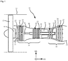
- Fig. 1 shows schematically and simplified an aircraft gas turbine 10, which is illustrated purely by way of example as a turbofan engine.
- the gas turbine 10 comprises a fan 12 which is surrounded by an indicated jacket 14.
- the fan 12 is followed by a compressor 16, which is received in an indicated inner housing 18 and can be designed in one or more stages.
- the combustion chamber 20 adjoins the compressor 16. Hot exhaust gas flowing out of the combustion chamber then flows through the adjoining turbine 22, which can be designed in one or more stages.
- the turbine 22 comprises a high pressure turbine 24 and a low pressure turbine 26.
- a hollow shaft 28 connects the high pressure turbine 24 to the compressor 16, in particular a high pressure compressor 29, so that these are driven or rotated together.
- a further inner shaft 30 in the radial direction RR of the turbine connects the low-pressure turbine 26 to the fan 12 and to a low-pressure compressor 32 here, so that these are driven or rotated together.
- a thrust nozzle 33 which is only indicated here, adjoins the turbine 22.
- an intermediate turbine housing 34 is arranged between the high-pressure turbine 24 and the low-pressure turbine 26 and is arranged around the shafts 28, 30.
- a transition duct can be provided between the high-pressure turbine 24 and the low-pressure turbine 26 instead of an intermediate turbine housing 34.
- Hot exhaust gases from the high-pressure turbine 24 flow through the intermediate turbine housing 34 in its radially outer region 36. The hot exhaust gas then passes into an annular space 38 of the low-pressure turbine 26.
- Rotor blade rings 27 of the compressors 28, 32 and the turbines 24, 26 are shown by way of example.
- Guide vane rings 31 that are normally present are shown by way of example only for compressor 32 for reasons of clarity.
- the low-pressure turbine 26 and the fan 12 are connected to one another by means of a gear 40 which is only indicated schematically here, in particular a planetary gear.
- the low-pressure turbine 26 becomes what is known as a high-speed one Turbine stage which has a higher rotational speed than the fan 12.
- the direction of rotation of the low-pressure turbine 26 can be the same as or different from the direction of rotation of the fan 12.
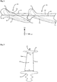
- the following description of an embodiment of the invention relates in particular to a turbine stage of the low-pressure turbine 26 in which a plurality of blades 42 according to FIG Fig. 2 are arranged side by side in the circumferential direction.
- the blade 42 has a shroud 44 radially on the outside.
- the blade 46 adjoins the shroud 44 radially inward.
- a single sealing element 48 in particular a single sealing fin 48, is arranged on the shroud 44.
- the sealing element 48 extends essentially in the circumferential direction UR and projects outward from the shroud 44 in the radial direction RR.
- mass can be reduced, which has a favorable effect on the forces acting on the blade 42 during operation.
- the blade 42 or its blade 46 can have different chord lengths Si or Sa radially on the inside and radially on the outside, which is exemplified in FIG Fig. 3 is shown.
- the chord length Si or Sa is measured between a leading edge 50 and a trailing edge 52 of the airfoil 46, as is also the case in FIG Fig. 2 for left vane 42 is shown.
- the radially inner chord length Si is determined above a blade root 52.
- the radially outer chord length Sa is determined below the shroud 44.
- the inner chord length Si is about 1.1 to 1.4 times the outer chord length Sa.
- a material application 56 can be provided on the sealing fin 48 and / or on the front edge 50 of the blade 46, which is used for armoring the remaining blade material.
- the blade 42 can in particular be made of a titanium aluminide (TiAl).
- An armoring 56 on the sealing fin 44 or the front edge 50 can be made from a ceramic material or from a Ni-based material such as boron nitride.
Landscapes
- Engineering & Computer Science (AREA)
- Mechanical Engineering (AREA)
- General Engineering & Computer Science (AREA)
- Chemical & Material Sciences (AREA)
- Materials Engineering (AREA)
- Ceramic Engineering (AREA)
- Physics & Mathematics (AREA)
- Fluid Mechanics (AREA)
- Turbine Rotor Nozzle Sealing (AREA)
Abstract
Description
- Die vorliegende Erfindung betrifft eine Schaufel für eine schnelllaufende Turbinenstufe einer Fluggasturbine, insbesondere eines Flugzeugtriebwerks.
- Bei einer schnelllaufenden Turbinenstufe, die insbesondere als Niederdruckturbine in einem Triebwerk mit Getriebfan, auch als GTF (geared Turbofan) bezeichnet, ergeben sich Werte für Umlaufgeschwindigkeit Utip an der Schaufelspitze von 300m/s und mehr. Im Vergleich dazu liegt die Umlaufgeschwiendigkeit Utip bei Turbinenstufen konventioneller Triebwerken bzw. bei nicht schnelllaufenden Turbinenstufen, die mit der Fan-Drehzahl laufen, bei maximal 250m/s.
- "Schnellaufend" bedeutet in diesem Zusammenhang, dass die betreffende Turbinenstufe mittels eines Getriebes mit dem Fan bzw. Triebwerkseintrittslaufradgekoppelt ist, so dass es sich im Betrieb der oder die betreffenden Laufschaufelkränze dieser Turbinenstufe schneller drehen als der Fan.
- Richtungsangaben wie "Axial-" bzw. "axial", "Radial-" bzw. "radial" und "Umfangs-" sind grundsätzlich auf die Maschinenachse der Fluggasturbine bezogen zu verstehen, sofern sich aus dem Kontext nicht explizit oder implizit etwas anderes ergibt.
- In schnellaufenden Turbinenstufen ist die Belastung auf die Schaufeln bzw. deren Schaufelblätter sehr groß. Insbesondere sind die Schaufelblätter im Betrieb einer höheren Fremdpartieklenergie in Folge der höheren Umlaufgeschwindigkeiten ausgesetzt, sogenannten Einschlägen bzw. Impacts, die zu Primär- und Folgeschäden an den Schaufeln führen. Dabei sind die Primär- und Folgeschäden umso größer, je schneller sich die Turbinenstufe bzw. die Schaufeln im Heißgasstrom drehen. Ferner sind auch starke Einflüsse der wirkenden Fliehkräfte auf die Schaufeln feststellbar. Dabei ist weiter zu berücksichtigen, dass für solche Schaufeln üblicherweise Nickel-Werkstoffe verwendet werden. Bei Verwendung von Schaufeln aus spröden Werkstoffen ist entsprechend stärkerer Verschleiß bzw. Schädigung festzustellen.
- Die der Erfindung zu Grunde liegende Aufgabe wird darin gesehen, eine Schaufel für eine schnelllaufende Turbinenstufe bereitzustellen, die eine verbesserte Robustheit aufweist im Betrieb.
- Dieser Aufgabe wird gelöst durch eine Schaufel mit den Merkmalen des Anspruchs 1, eine Turbinenstufe mit den Merkmalen des Anspruchs 7 und durch ein Flugzeugtriebwerk mit den Merkmalen des Anspruchs 9. Vorteilhafte Ausgestaltungen mit zweckmäßigen Weiterbildungen sind in den abhängigen Patentansprüchen angegeben.
- Vorgeschlagen wird also eine Schaufel für eine schnelllaufende Turbinenstufe einer Fluggasturbine, insbesondere eines Flugzeugtriebwerks, mit einem radial innen angeordneten Schaufelfuß, einem radial äußeren Deckband, und mit einem Schaufelblatt, das sich zwischen dem Schaufelfuß und dem Deckband erstreckt. Dabei ist vorgesehen, dass das äußere Deckband nur ein einziges radial von dem Deckband vorstehendes Dichtelement, insbesondere nur einen einzigen Dichtfin, umfasst.
- "Schnelllaufend" kann insbesondere bedeuten, dass die Schaufel für ein An2 ≥ 4000 m2/s2, vorzugsweise ≥ 4500 m2/s2, insbesondere ≥ 5000 m2/s2 im ADP-Bereich der Fluggasturbine (10) ausgelegt ist und/oder für ein(e) entsprechend ausgelegte(s) Turbinenstufe/Fluggasturbine geeignet und/oder bestimmt sind. "An2" ist dabei die Ringraumfläche A am Austritt der Turbinenstufe multipliziert mit dem Quadrat der Drehzahl n. "ADP" steht für "Aerodynamic Design Point", d.h. den Betriebszustand auf Reiseflughöhe, der auch "cruise condition" genannt wird. Bei konventionellen, nicht schnelllaufenden Turbinenstufen beträgt An2 im ADP-Bereich dagegen deutlich unter 2000 m2/s2.
- Durch das Vorsehen von lediglich einem Dichtelement bzw. einem Dichtfin an dem Deckband kann eine Reduzierung der Randlast der Schaufel erreicht werden. Durch die Einsparung von Masse an den radial äußersten Bereichen der Schaufel können die wirkenden Fliehkräfte maßgeblich reduziert werden. Somit können insbesondere in dem Schaufelblatt bzw. dem Schaufelprofil auftretende Spannungen reduziert werden. Mit zunehmender Spannung und mit abnehmender Duktilität des Schaufelwerkstoffs nimmt die Robustheit der Schaufel gegenüber Schlagbeanspruchung ab. Das nur eine Dichtelement ermöglicht eine verbesserte Robustheit insbesondere im Hinblick auf höhere Drehzahlen und weniger duktile Schaufelwerkstoffe.
- Das Schaufelblatt kann radial innen eine innere Sehnenlänge aufweisen, die mindestens das 1,1-fache, vorzugsweise mindestens das 1,2-fache, insbesondere mindestens das 1,3-fache von einer radial äußeren Sehnenlänge beträgt, wobei die innere Sehnenlänge unmittelbar oberhalb des Schaufelfußes an dem Schaufelblatt gemessen ist und die äußere Sehnenlänge unmittelbar unterhalb des Deckbandes an dem Schaufelblatt gemessen ist. Die Sehnenlänge verändert sich somit über die radiale Erstreckung des Schaufelblatts im Vergleich zu einer konventionellen Turbinenschaufel, bei der die innere Sehnenlänge weniger als 10% länger als die äußeren Sehnenlänge ist, in besonders hohem Maße. Dies kann aus aerodynamischen Gesichtspunkten zwar zunächst nachteilig sein, gestattet dafür aber eine besonders vorteilhafte Verteilung der Mittelspannung und des Widerstandsmoments über die Schaufelhöhe. Dadurch kann die Robustheit gegenüber Schlagbeanspruchung, insbesondere bei hohen Drehzahlen und vergleichsweise wenig duktilen Werkstoffen, insbesondere spröden Werkstoffen wie z.B. TiAl, weiter verbessert werden.
Die Schaufel kann aus einem spröden Werkstoff, beispielsweise einer Titanaluminid-Legierung hergestellt sein. Dabei kann die Schaufel gegossen oder geschmiedet oder/und additiv, beispielsweise durch (selektives) Elektronenstrahlschmelzen (s)EBM, gefertigt sein. Unter dem Begriff spröde Werkstoffe, wie beispielsweis TiAl, sind Werkstoffe zu verstehen, bei denen eine maximale totale Dehnung von <2% bei Raumtemperatur auftritt. - An dem Schaufelblatt können wenigstens abschnittsweise Materialverdickungen vorgesehen sein, insbesondere eine zumindest abschnittsweise verdickte Vorderkante. Hierdurch kann Schädigungen aufgrund der erhöhten Fremdpartikelenergie, insbesondere den sogenannten Impacts, entgegengewirkt werden und die Robustheit noch weiter verbessert werden.
- An dem Schaufelblatt oder/und an dem Dichtelement kann zumindest abschnittsweise eine Panzerung aus einem von dem Material der Schaufel unterschiedlichen Material ausgebildet ist, insbesondere aus einem keramischen Material oder aus einem Ni-basierten Material. Eine derartige teilweise oder vollständige Panzerung ermöglicht eine Verstärkung der Schaufel, um Schädigungen entgegenzuwirken.
- Ferner wird eine Turbinenstufe für eine Gasturbine, insbesondere Fluggasturbine vorgeschlagen mit mehreren in Umfangsrichtung nebeneinander angeordneten, oben beschriebenen Schaufeln. Bei einer solchen Turbinenstufe können in Umfangsrichtung benachbarte Schaufeln derart ausgebildet sein, dass sie unterschiedliche Eigenfrequenzen aufweisen. Hierzu können benachbarte Schaufeln beispielsweise jeweils voneinander unterschiedliche Geometrien des Schaufelblatts oder/und des Deckbandes aufweisen.
- Für das Deckband kann eine Kühlung vorgesehen sein. Beispielsweise kann von außerhalb der Schaufel und des Deckbandes Kühlluft zugeführt werden. Alternativ oder zusätzlich kann die Schaufel und/oder das Deckband auch von innen gekühlt werden. Durch eine Kühlung, insbesondere des anstreifenden, thermisch besonders belasteten radial äußeren Deckbandes, kann die Temperatur des Deckbandes im Betrieb der Fluggasturbine reduziert werden. Dadurch kann das temperaturabhängige Kriechverhalten hin zu einer größeren Kriechresistenz verbessert werden. Dies gestattet die Wahl eines robusteren, duktileren Werkstoffs, bspw. einer Titanaluminid(TiAl)-Legierung mit einer duktileren Mikrostruktur, dessen Kriechresistenz erst durch die Kühlung in einen gewünschten Bereich verschoben wird. Auch hierdurch kann die Robustheit werter verbessert werden.
- An wenigstens einer Schaufel der Turbinenstufe kann ein Schaufeldeckbandgewicht angeordnet sein, das derart aus-gebildet ist, dass sich in allen Profilschnitten des Schaufelprofils eine statische Mittelspannung von kleiner als 150MPa einstellt
- Das Schaufeldeckbandgewicht kann weniger als 7 Gramm wiegen.
- Schließlich wird auch ein Flugzeugtriebwerk mit einer oben erwähnten schnelllaufenden Turbinenstufe vorgeschlagen, wobei die Turbinenstufe im Betrieb des Flugzeugtriebwerks schneller dreht als ein Fan des Flugtriebwerks. Es handelt sich hierbei also um ein Flugzeugtriebwerk mit einem sogenannten Getriebefan bzw. geared Turbofan (GTF).
- Bei einem solchen Flugzeugtriebwerk kann eine Zuleitung von Kühlfluid, insbesondere Kühlluft, zu der Kühleinrichtung in dem Deckband der Schaufeln der Turbinenstufe von stromaufwärts erfolgen. Dabei kann die Kühlluft beispielsweise durch stromaufwärts angeordnete Leitschaufeln hindurch bereitgestellt werden.
- Nachfolgend wird die Erfindung unter Bezugnahme auf die anliegenden Figuren beispielhaft und nicht einschränkend beschrieben.
-
Fig. 1 zeigt in einer vereinfachten schematischen Darstellung ein Prinzipbild einer Fluggasturbine bzw. eines Flugzeugtriebwerks. -
Fig. 2 zeigt in einer stark vereinfachten schematischen Draufsicht von radial außen zwei in Umfangsrichtung nebeneinander angeordnete Schaufeln einer Turbinenstufe. -
Fig. 3 zeigt in einer schematischen Darstellung eine Schaufel mit ihren Sehnenlängen. -
Fig. 1 zeigt schematisch und vereinfacht eine Fluggasturbine 10, die rein beispielhaft als Mantelstromtriebwerk illustriert ist. Die Gasturbine 10 umfasst einen Fan 12, der von einem angedeuteten Mantel 14 umgeben ist. In Axialrichtung AR der Gasturbine 10 schließt sich an den Fan 12 ein Verdichter 16 an, der in einem angedeuteten inneren Gehäuse 18 aufgenommen ist und einstufig oder mehrstufig ausgebildet sein kann. An den Verdichter 16 schließt sich die Brennkammer 20 an. Aus der Brennkammer ausströmendes heißes Abgas strömt dann durch die sich anschließende Turbine 22, die einstufig oder mehrstufig ausgebildet sein kann. Im vorliegenden Beispiel umfasst die Turbine 22 eine Hochdruckturbine 24 und eine Niederdruckturbine 26. Eine Hohlwelle 28 verbindet die Hochdruckturbine 24 mit dem Verdichter 16, insbesondere einem Hochdruckverdichter 29, so dass diese gemeinsam angetrieben bzw. gedreht werden. Eine in Radialrichtung RR der Turbine weitere innen liegende Welle 30 verbindet die Niederdruckturbine 26 mit dem Fan 12 und mit einem hier Niederdruckverdichter 32, so dass diese gemeinsam angetrieben bzw. gedreht werden. An die Turbine 22 schließt sich eine hier nur angedeutete Schubdüse 33 an. - Im dargestellten Beispiel einer Fluggasturbine 10 ist zwischen der Hochdruckturbine 24 und der Niederdruckturbine 26 ein Turbinenzwischengehäuse 34 angeordnet, das um die Wellen 28, 30 angeordnet ist. Zwischen der Hochdruckturbine 24 und der Niederdruckturbine 26 kann bei andere Konstruktionen auch lediglich ein Übergangskanal vorgesehen sein statt eines Turbinenzwischengehäuses 34. In seinem radial äußeren Bereich 36 wird das Turbinenzwischengehäuse 34 von heißen Abgasen aus der Hochdruckturbine 24 durchströmt. Das heiße Abgas gelangt dann in einen Ringraum 38 der Niederdruckturbine 26. Von den Verdichtern 28, 32 und den Turbinen 24, 26 sind beispielhaft Laufschaufelkränze 27 dargestellt. Üblicherweise vorhandene Leitschaufelkränze 31 sind aus Gründen der Übersicht beispielhaft nur bei dem Verdichter 32 dargestellt.
- Die Niederdruckturbine 26 und der Fan 12 sind in diesem Beispiel mittels eines hier nur schematisch angedeuteten Getriebes 40 miteinander, insbesondere eines Planetengetriebes, verbunden. Hierdurch wird die Niederdruckturbine 26 zu einer sogenannt schnelllaufenden Turbinenstufe, die eine höhere Umlaufgeschwindigkeit aufweist als der Fan 12. Dabei kann der Drehsinn der Niederdruckturbine 26 gleich oder verschieden zum Drehsinn des Fans 12 sein.
- Die nachfolgende Beschreibung einer Ausführungsform der Erfindung bezieht sich insbesondere auf eine Turbinenstufe der Niederdruckturbine 26, in der mehrere Schaufeln 42 gemäß
Fig. 2 in Umfangsrichtung nebeneinander angeordnet sind. - Die Schaufel 42 weist radial außen ein Deckband 44 auf. Nach radial innen schließt sich an das Deckband 44 das Schaufelblatt 46 an. An dem Deckband 44 ist ein einziges Dichtelement 48, insbesondere ein einzelner Dichtfin 48, angeordnet. Das Dichtelement 48 erstreckt sich im Wesentlichen in Umfangsrichtung UR und steht von dem Deckband 44 in Radialrichtung RR nach außen vor. Im Gegensatz zu bekannten Schaufeln mit üblicherweise zwei Dichtelementen, kann durch das Vorsehen von lediglich einem Dichtfin 48 im radial äußeren Bereich der Schaufel 42 Masse reduziert werden, was sich günstig auf die im Betrieb auf die Schaufel 42 wirkenden Kräfte auswirkt.
- Ergänzend zum Vorsehen von lediglich einem radial äußeren Dichtfin 48 kann die Schaufel 42 bzw. deren Schaufelblatt 46 radial innen und radial außen unterschiedliche Sehnenlängen Si bzw. Sa aufweisen, was beispielhaft in der
Fig. 3 dargestellt ist. Dabei wird die Sehnenlänge Si bzw. Sa zwischen einer Vorderkante 50 und einer Hinterkante 52 des Schaufelblatts 46 gemessen, wie dies auch in derFig. 2 für die linke Schaufel 42 gezeigt ist. - Die radial innere Sehnenlänge Si wird dabei oberhalb eines Schaufelfußes 52 bestimmt. Die radial äußere Sehnenlänge Sa wird unterhalb des Deckbandes 44 bestimmt. Die innere Sehnenlänge Si beträgt dabei etwa das 1,1-fache bis 1,4-fache der äußeren Sehnenlänge Sa.
- An dem Dichtfin 48 oder/und an der Vorderkante 50 des Schaufelblatts 46 kann ein Materialauftrag 56 vorgesehen sein, der zur Panzerung des übrigen Schaufelmaterials dient. Die Schaufel 42 kann insbesondere aus einem Titanaluminid (TiAl) hergestellt sein. Eine Panzerung 56 am Dichtfin 44 bzw. der Vorderkante 50 kann aus einem keramischen Material oder aus einem Ni-basierten Material, wie etwa Bornitrid, hergestellt sein.
-
- 10
- Fluggasturbine
- 12
- Fan
- 14
- Mantel
- 16
- Verdichter
- 18
- Gehäuse
- 20
- Brennkammer
- 22
- Turbine
- 24
- Hochdruckturbine
- 26
- Niederdruckturbine
- 27
- Laufschaufelkranz
- 28
- Hohlwelle
- 29
- Hochdruckverdichter
- 30
- Welle
- 31
- Leitschaufelkranz
- 32
- Niederdruckverdichter
- 33
- Schubdüse
- 34
- Turbinenzwischengehäuse
- 36
- radial äußerer Bereich
- 38
- Ringraum
- 40
- Getriebe
- 42
- Schaufel
- 44
- Deckband
- 46
- Schaufelblatt
- 48
- Dichtelement
- 50
- Vorderkante
- 52
- Hinterkante
- 54
- Schaufelfuß
- 56
- Panzerung
- AR
- Axialrichtung
- RR
- Radialrichtung
- Si
- radial innere Sehnenlänge
- Sa
- radial äußere Sehnenlänge
- UR
- Umfangsrichtung
Claims (12)
- Schaufel für eine schnelllaufende Turbinenstufe (26) einer Fluggasturbine (10), insbesondere eines Flugzeugtriebwerks, mit
einem radial innen angeordneten Schaufelfuß (52),
einem radial äußeren Deckband (44), und
einem Schaufelblatt (46), das sich zwischen dem Schaufelfuß (52) und dem Deckband (44) erstreckt,
dadurch gekennzeichnet, dass das äußere Deckband (44) nur ein einziges radial von dem Deckband (44) vorstehendes Dichtelement (48), insbesondere nur einen einzigen Dichtfin, umfasst. - Schaufel nach Anspruch 1, dadurch gekennzeichnet, dass die Schaufel für ein An2 ≥ 4000 m2/s2, vorzugsweise ≥ 4500 m2/s2, insbesondere ≥ 5000 m2/s2 im ADP-Bereich der Fluggasturbine (10) ausgelegt ist und/oder für eine dafür ausgelegte Turbinenstufe (26) oder Fluggasturbine (10) geeignet und/oder bestimmt ist.
- Schaufel nach Anspruch 1 oder 2, dadurch gekennzeichnet, dass das Schaufelblatt (46) radial innen eine innere Sehnenlänge (Si) aufweist, die mindestens das 1,1-fache bis 1,4-fache von einer radial äußeren Sehnenlänge (Sa) beträgt, wobei die innere Sehnenlänge (Si) unmittelbar oberhalb des Schaufelfußes (52) an dem Schaufelblatt (46) gemessen ist und die äußere Sehnenlänge (Sa) unmittelbar unterhalb des Deckbandes (44) an dem Schaufelblatt (46) gemessen ist.
- Schaufel nach einem der vorhergehenden Ansprüche, dadurch gekennzeichnet, dass die Schaufel (42) aus einem spröden Werkstoff, beispielsweise einer Titanaluminid-Legierung, hergestellt ist, insbesondere gegossen, geschmiedet oder/und additiv gefertigt ist.
- Schaufel nach einem der vorhergehenden Ansprüche, dadurch gekennzeichnet, dass an dem Schaufelblatt (46) wenigstens abschnittsweise Materialverdickungen vorgesehen sind, insbesondere eine zumindest abschnittsweise verdickte Vorderkante (50) .
- Schaufel nach einem der vorhergehenden Ansprüche, dadurch gekennzeichnet, dass an dem Schaufelblatt (46) oder/und an dem Dichtelement (48) zumindest abschnittsweise eine Panzerung (56) aus einem von dem Material der Schaufel (42) unterschiedlichen Material ausgebildet ist, insbesondere aus einem keramischen Material oder aus einem Ni-basierten Material.
- Turbinenstufe für eine Gasturbine, insbesondere Fluggasturbine (10) mit mehreren in Umfangsrichtung (UR) nebeneinander angeordneten Schaufeln (42) nach einem der vorhergehenden Ansprüche.
- Turbinenstufe nach Anspruch 7, dadurch gekennzeichnet, dass für das Deckband (44) eine Kühlung vorgesehen ist.
- Turbinenstufe nach Anspruch 7 oder 8, dadurch gekennzeichnet, dass in Umfangsrichtung (UR) benachbarte Schaufeln (42) derart ausgebildet sind, dass sie unterschiedliche Eigenfrequenzen aufweisen, insbesondere eine voneinander unterschiedliche Geometrie des Schaufelblatts (46) und/oder des Deckbandes (44) aufweisen.
- Turbinenstufe nach Anspruch 8 oder 9, dadurch gekennzeichnet, dass eine Zuleitung von Kühlfluid, insbesondere Kühlluft, zu der Kühleinrichtung in dem Deckband (44) der Schaufeln (42) der Turbinenstufe (26) von stromaufwärts erfolgt.
- Turbinenstufe nach einem der Ansprüche 7 bis 10, dadurch gekennzeichnet, dass an wenigstens einer Schaufel (42) ein Schaufeldeckbandgewicht angeordnet ist, das derart ausgebildet ist, dass sich in allen Profilschnitten des Schaufelprofils eine statische Mittelspannung von kleiner als 150MPa einstellt und/oder wobei das Schaufeldeckbandgewicht weniger als 7 Gramm wiegt.
- Flugzeugtriebwerk mit einer schnelllaufenden Turbinenstufe nach einem der Ansprüche 7 bis 11, dadurch gekennzeichnet, dass die Turbinenstufe (26) im Betrieb des Flugzeugtriebwerks (10) schneller dreht als ein Fan (12) des Flugtriebwerks (10).
Applications Claiming Priority (1)
| Application Number | Priority Date | Filing Date | Title |
|---|---|---|---|
| DE102019202387.8A DE102019202387A1 (de) | 2019-02-21 | 2019-02-21 | Schaufel für eine schnelllaufende Turbinenstufe mit einzelnem Dichtelement |
Publications (2)
| Publication Number | Publication Date |
|---|---|
| EP3699399A1 true EP3699399A1 (de) | 2020-08-26 |
| EP3699399B1 EP3699399B1 (de) | 2024-10-02 |
Family
ID=69804402
Family Applications (1)
| Application Number | Title | Priority Date | Filing Date |
|---|---|---|---|
| EP20158370.5A Active EP3699399B1 (de) | 2019-02-21 | 2020-02-20 | Schaufel für eine schnelllaufende turbinenstufe mit einzelnem dichtelement |
Country Status (4)
| Country | Link |
|---|---|
| US (1) | US11230933B2 (de) |
| EP (1) | EP3699399B1 (de) |
| DE (1) | DE102019202387A1 (de) |
| ES (1) | ES2994455T3 (de) |
Families Citing this family (3)
| Publication number | Priority date | Publication date | Assignee | Title |
|---|---|---|---|---|
| FR3143676A1 (fr) * | 2022-12-16 | 2024-06-21 | Safran Aircraft Engines | système PROPULSIF AERONAUTIQUE |
| FR3143683A1 (fr) * | 2022-12-16 | 2024-06-21 | Safran Aircraft Engines | Systeme propulsif aeronautique |
| US12509988B2 (en) | 2024-06-14 | 2025-12-30 | Pratt & Whitney Canada Corp. | Turbine engine airfoil |
Citations (4)
| Publication number | Priority date | Publication date | Assignee | Title |
|---|---|---|---|---|
| EP2617944A2 (de) * | 2012-01-20 | 2013-07-24 | General Electric Company | Turbomaschinenschaufelspitzendeckbänder |
| EP2626517A2 (de) * | 2012-02-08 | 2013-08-14 | General Electric Company | Rotierende Anordnung für eine Turbinenanordnung |
| EP3168420A1 (de) * | 2015-11-11 | 2017-05-17 | Rolls-Royce plc | Turbinenschaufel mit deckband |
| EP3314093A1 (de) * | 2015-06-29 | 2018-05-02 | Siemens Aktiengesellschaft | Ummantelte turbinenschaufel |
Family Cites Families (24)
| Publication number | Priority date | Publication date | Assignee | Title |
|---|---|---|---|---|
| DE4310896C1 (de) | 1993-04-02 | 1994-03-24 | Thyssen Industrie | Verfahren zum Herstellen von verschleißfesten Kanten an Turbinenschaufeln |
| US5476363A (en) | 1993-10-15 | 1995-12-19 | Charles E. Sohl | Method and apparatus for reducing stress on the tips of turbine or compressor blades |
| DE4439950C2 (de) * | 1994-11-09 | 2001-03-01 | Mtu Muenchen Gmbh | Metallisches Bauteil mit einer Verbundbeschichtung, Verwendung, sowie Verfahren zur Herstellung von metallischen Bauteilen |
| US5966525A (en) | 1997-04-09 | 1999-10-12 | United Technologies Corporation | Acoustically improved gas turbine blade array |
| DE10047307A1 (de) * | 2000-09-25 | 2002-08-01 | Alstom Switzerland Ltd | Dichtungsanordnung |
| EP1789654B1 (de) * | 2004-09-16 | 2017-08-23 | General Electric Technology GmbH | Strömungsmaschinenschaufel mit fluidisch gekühltem deckband |
| US20060280610A1 (en) * | 2005-06-13 | 2006-12-14 | Heyward John P | Turbine blade and method of fabricating same |
| US7771171B2 (en) | 2006-12-14 | 2010-08-10 | General Electric Company | Systems for preventing wear on turbine blade tip shrouds |
| US8192166B2 (en) * | 2009-05-12 | 2012-06-05 | Siemens Energy, Inc. | Tip shrouded turbine blade with sealing rail having non-uniform thickness |
| US10294795B2 (en) | 2010-04-28 | 2019-05-21 | United Technologies Corporation | High pitch-to-chord turbine airfoils |
| US8951013B2 (en) * | 2011-10-24 | 2015-02-10 | United Technologies Corporation | Turbine blade rail damper |
| DE102011086524A1 (de) | 2011-11-17 | 2013-05-23 | Mtu Aero Engines Gmbh | Panzerung von Dichtfins von TiAl-Schaufeln durch induktives Auftragslöten von Hartstoffpartikeln |
| EP2789802B1 (de) | 2013-04-09 | 2022-07-13 | MTU Aero Engines AG | Schaufelgitter für eine Turbomaschine und zugehöriges Herstellungsverfahren |
| EP2842662B1 (de) | 2013-09-03 | 2020-08-05 | MTU Aero Engines GmbH | Schaufelspitzenpanzerung für Titanschaufeln |
| US9464530B2 (en) | 2014-02-20 | 2016-10-11 | General Electric Company | Turbine bucket and method for balancing a tip shroud of a turbine bucket |
| US20160146040A1 (en) * | 2014-11-25 | 2016-05-26 | United Technologies Corporation | Alternating Vane Asymmetry |
| CN107208486B (zh) | 2015-02-10 | 2019-08-06 | 三菱日立电力系统株式会社 | 涡轮、燃气轮机以及涡轮动叶 |
| US20160238021A1 (en) * | 2015-02-16 | 2016-08-18 | United Technologies Corporation | Compressor Airfoil |
| US9951632B2 (en) * | 2015-07-23 | 2018-04-24 | Honeywell International Inc. | Hybrid bonded turbine rotors and methods for manufacturing the same |
| WO2017018981A1 (en) | 2015-07-24 | 2017-02-02 | Siemens Aktiengesellschaft | Turbine blade with contoured tip shroud |
| US20170145827A1 (en) | 2015-11-23 | 2017-05-25 | United Technologies Corporation | Turbine blade with airfoil tip vortex control |
| US10184342B2 (en) | 2016-04-14 | 2019-01-22 | General Electric Company | System for cooling seal rails of tip shroud of turbine blade |
| US10837287B2 (en) * | 2017-01-20 | 2020-11-17 | Pratt & Whitney Canada Corp. | Mistuned bladed rotor and associated manufacturing method |
| US10801325B2 (en) | 2017-03-27 | 2020-10-13 | Raytheon Technologies Corporation | Turbine blade with tip vortex control and tip shelf |
-
2019
- 2019-02-21 DE DE102019202387.8A patent/DE102019202387A1/de not_active Withdrawn
-
2020
- 2020-02-18 US US16/793,384 patent/US11230933B2/en active Active
- 2020-02-20 EP EP20158370.5A patent/EP3699399B1/de active Active
- 2020-02-20 ES ES20158370T patent/ES2994455T3/es active Active
Patent Citations (4)
| Publication number | Priority date | Publication date | Assignee | Title |
|---|---|---|---|---|
| EP2617944A2 (de) * | 2012-01-20 | 2013-07-24 | General Electric Company | Turbomaschinenschaufelspitzendeckbänder |
| EP2626517A2 (de) * | 2012-02-08 | 2013-08-14 | General Electric Company | Rotierende Anordnung für eine Turbinenanordnung |
| EP3314093A1 (de) * | 2015-06-29 | 2018-05-02 | Siemens Aktiengesellschaft | Ummantelte turbinenschaufel |
| EP3168420A1 (de) * | 2015-11-11 | 2017-05-17 | Rolls-Royce plc | Turbinenschaufel mit deckband |
Also Published As
| Publication number | Publication date |
|---|---|
| US20200271002A1 (en) | 2020-08-27 |
| ES2994455T3 (en) | 2025-01-24 |
| DE102019202387A1 (de) | 2020-08-27 |
| US11230933B2 (en) | 2022-01-25 |
| EP3699399B1 (de) | 2024-10-02 |
Similar Documents
| Publication | Publication Date | Title |
|---|---|---|
| EP3699398A1 (de) | Deckbandlose schaufel für eine schnelllaufende turbinenstufe | |
| EP3999716B1 (de) | Laufschaufel für eine strömungsmaschine, zugehöriges turbinenmodul und verwendung derselben | |
| EP3699399B1 (de) | Schaufel für eine schnelllaufende turbinenstufe mit einzelnem dichtelement | |
| EP3091177B1 (de) | Rotor für eine strömungsmaschine und verdichter | |
| EP2044293B1 (de) | Gasturbine mit einem mantelringsegment, das einen rezirkulationskanal umfasst | |
| DE102009003523A1 (de) | Dampfturbinen-Schaufel für Niederdruck-Abschnitt | |
| DE3812027A1 (de) | Propfan-turbotriebwerk | |
| DE102017115042A1 (de) | Deckbandkonfigurationen für Turbinenlaufschaufeln | |
| EP3034788B1 (de) | Kompressorschaufel einer gasturbine | |
| DE102015102396A1 (de) | Turbinenschaufel und Verfahren zum Auswuchten eines Spitzendeckbandes einer Turbinenschaufel und Gasturbine | |
| EP3561236B1 (de) | Leitschaufel für eine turbine einer strömungsmaschine, turbinenmodul und verwendung eines turbinenmoduls | |
| US12180855B2 (en) | Rotor blade for a turbomachine | |
| EP3495639B1 (de) | Verdichtermodul für eine strömungsmaschine, das die grenzschicht in einem verdichterzwischengehäuse abbaut | |
| EP3274561B1 (de) | Laufschaufel für eine gasturbine, herstellungsverfahren und nachbearbeitungsverfahren | |
| EP4227489A1 (de) | Leitschaufel für eine strömungsmaschine | |
| EP4209657A1 (de) | Schaufel, insbesondere laufschaufel oder leitschaufel, mit asymmetrischem vorderkantenprofil für eine gasturbine | |
| DE102010040823A1 (de) | Turbolader | |
| WO2015082624A1 (de) | Verdichterrad | |
| EP1721063B1 (de) | Strömungsmaschine und verfahren zur anpassung von stator und rotor einer strömungsmaschine | |
| EP2453108B1 (de) | Rotor für eine Strömungsmaschine | |
| EP4004344A1 (de) | Laufschaufel für eine strömungsmaschine, zugehöriges turbinenmodul und verwendung derselben | |
| EP4166754A1 (de) | Rotoranordnung für eine gasturbine mit an rotorsegmenten ausgebildeten, geneigten axialen kontaktflächen, gasturbine und fluggasturbine | |
| EP4227491A1 (de) | Laufschaufel für eine gasturbine, system mit einer laufschaufel und einem schaufelfussschutzblech, laufschaufelscheibe und gasturbine | |
| WO2021110191A1 (de) | Dichtungsträger für eine turbomaschine mit schlitzartigen öffnungen im dichtungskörper | |
| WO2021083441A1 (de) | Laufschaufelanordnung für eine strömungsmaschine |
Legal Events
| Date | Code | Title | Description |
|---|---|---|---|
| PUAI | Public reference made under article 153(3) epc to a published international application that has entered the european phase |
Free format text: ORIGINAL CODE: 0009012 |
|
| STAA | Information on the status of an ep patent application or granted ep patent |
Free format text: STATUS: THE APPLICATION HAS BEEN PUBLISHED |
|
| AK | Designated contracting states |
Kind code of ref document: A1 Designated state(s): AL AT BE BG CH CY CZ DE DK EE ES FI FR GB GR HR HU IE IS IT LI LT LU LV MC MK MT NL NO PL PT RO RS SE SI SK SM TR |
|
| AX | Request for extension of the european patent |
Extension state: BA ME |
|
| STAA | Information on the status of an ep patent application or granted ep patent |
Free format text: STATUS: REQUEST FOR EXAMINATION WAS MADE |
|
| 17P | Request for examination filed |
Effective date: 20210223 |
|
| RBV | Designated contracting states (corrected) |
Designated state(s): AL AT BE BG CH CY CZ DE DK EE ES FI FR GB GR HR HU IE IS IT LI LT LU LV MC MK MT NL NO PL PT RO RS SE SI SK SM TR |
|
| STAA | Information on the status of an ep patent application or granted ep patent |
Free format text: STATUS: EXAMINATION IS IN PROGRESS |
|
| 17Q | First examination report despatched |
Effective date: 20220603 |
|
| GRAP | Despatch of communication of intention to grant a patent |
Free format text: ORIGINAL CODE: EPIDOSNIGR1 |
|
| STAA | Information on the status of an ep patent application or granted ep patent |
Free format text: STATUS: GRANT OF PATENT IS INTENDED |
|
| INTG | Intention to grant announced |
Effective date: 20240605 |
|
| GRAS | Grant fee paid |
Free format text: ORIGINAL CODE: EPIDOSNIGR3 |
|
| GRAA | (expected) grant |
Free format text: ORIGINAL CODE: 0009210 |
|
| STAA | Information on the status of an ep patent application or granted ep patent |
Free format text: STATUS: THE PATENT HAS BEEN GRANTED |
|
| AK | Designated contracting states |
Kind code of ref document: B1 Designated state(s): AL AT BE BG CH CY CZ DE DK EE ES FI FR GB GR HR HU IE IS IT LI LT LU LV MC MK MT NL NO PL PT RO RS SE SI SK SM TR |
|
| REG | Reference to a national code |
Ref country code: GB Ref legal event code: FG4D Free format text: NOT ENGLISH |
|
| REG | Reference to a national code |
Ref country code: CH Ref legal event code: EP |
|
| REG | Reference to a national code |
Ref country code: IE Ref legal event code: FG4D Free format text: LANGUAGE OF EP DOCUMENT: GERMAN |
|
| REG | Reference to a national code |
Ref country code: DE Ref legal event code: R096 Ref document number: 502020009354 Country of ref document: DE |
|
| REG | Reference to a national code |
Ref country code: ES Ref legal event code: FG2A Ref document number: 2994455 Country of ref document: ES Kind code of ref document: T3 Effective date: 20250124 |
|
| REG | Reference to a national code |
Ref country code: LT Ref legal event code: MG9D |
|
| REG | Reference to a national code |
Ref country code: NL Ref legal event code: MP Effective date: 20241002 |
|
| PG25 | Lapsed in a contracting state [announced via postgrant information from national office to epo] |
Ref country code: NL Free format text: LAPSE BECAUSE OF FAILURE TO SUBMIT A TRANSLATION OF THE DESCRIPTION OR TO PAY THE FEE WITHIN THE PRESCRIBED TIME-LIMIT Effective date: 20241002 |
|
| PG25 | Lapsed in a contracting state [announced via postgrant information from national office to epo] |
Ref country code: NL Free format text: LAPSE BECAUSE OF FAILURE TO SUBMIT A TRANSLATION OF THE DESCRIPTION OR TO PAY THE FEE WITHIN THE PRESCRIBED TIME-LIMIT Effective date: 20241002 |
|
| PG25 | Lapsed in a contracting state [announced via postgrant information from national office to epo] |
Ref country code: HR Free format text: LAPSE BECAUSE OF FAILURE TO SUBMIT A TRANSLATION OF THE DESCRIPTION OR TO PAY THE FEE WITHIN THE PRESCRIBED TIME-LIMIT Effective date: 20241002 Ref country code: IS Free format text: LAPSE BECAUSE OF FAILURE TO SUBMIT A TRANSLATION OF THE DESCRIPTION OR TO PAY THE FEE WITHIN THE PRESCRIBED TIME-LIMIT Effective date: 20250202 Ref country code: PT Free format text: LAPSE BECAUSE OF FAILURE TO SUBMIT A TRANSLATION OF THE DESCRIPTION OR TO PAY THE FEE WITHIN THE PRESCRIBED TIME-LIMIT Effective date: 20250203 |
|
| PG25 | Lapsed in a contracting state [announced via postgrant information from national office to epo] |
Ref country code: FI Free format text: LAPSE BECAUSE OF FAILURE TO SUBMIT A TRANSLATION OF THE DESCRIPTION OR TO PAY THE FEE WITHIN THE PRESCRIBED TIME-LIMIT Effective date: 20241002 |
|
| PG25 | Lapsed in a contracting state [announced via postgrant information from national office to epo] |
Ref country code: BG Free format text: LAPSE BECAUSE OF FAILURE TO SUBMIT A TRANSLATION OF THE DESCRIPTION OR TO PAY THE FEE WITHIN THE PRESCRIBED TIME-LIMIT Effective date: 20241002 |
|
| PG25 | Lapsed in a contracting state [announced via postgrant information from national office to epo] |
Ref country code: NO Free format text: LAPSE BECAUSE OF FAILURE TO SUBMIT A TRANSLATION OF THE DESCRIPTION OR TO PAY THE FEE WITHIN THE PRESCRIBED TIME-LIMIT Effective date: 20250102 |
|
| PG25 | Lapsed in a contracting state [announced via postgrant information from national office to epo] |
Ref country code: GR Free format text: LAPSE BECAUSE OF FAILURE TO SUBMIT A TRANSLATION OF THE DESCRIPTION OR TO PAY THE FEE WITHIN THE PRESCRIBED TIME-LIMIT Effective date: 20250103 Ref country code: LV Free format text: LAPSE BECAUSE OF FAILURE TO SUBMIT A TRANSLATION OF THE DESCRIPTION OR TO PAY THE FEE WITHIN THE PRESCRIBED TIME-LIMIT Effective date: 20241002 |
|
| PG25 | Lapsed in a contracting state [announced via postgrant information from national office to epo] |
Ref country code: CZ Free format text: LAPSE BECAUSE OF FAILURE TO SUBMIT A TRANSLATION OF THE DESCRIPTION OR TO PAY THE FEE WITHIN THE PRESCRIBED TIME-LIMIT Effective date: 20241002 Ref country code: PL Free format text: LAPSE BECAUSE OF FAILURE TO SUBMIT A TRANSLATION OF THE DESCRIPTION OR TO PAY THE FEE WITHIN THE PRESCRIBED TIME-LIMIT Effective date: 20241002 |
|
| PG25 | Lapsed in a contracting state [announced via postgrant information from national office to epo] |
Ref country code: RS Free format text: LAPSE BECAUSE OF FAILURE TO SUBMIT A TRANSLATION OF THE DESCRIPTION OR TO PAY THE FEE WITHIN THE PRESCRIBED TIME-LIMIT Effective date: 20250102 |
|
| PG25 | Lapsed in a contracting state [announced via postgrant information from national office to epo] |
Ref country code: SM Free format text: LAPSE BECAUSE OF FAILURE TO SUBMIT A TRANSLATION OF THE DESCRIPTION OR TO PAY THE FEE WITHIN THE PRESCRIBED TIME-LIMIT Effective date: 20241002 |
|
| REG | Reference to a national code |
Ref country code: DE Ref legal event code: R097 Ref document number: 502020009354 Country of ref document: DE |
|
| PG25 | Lapsed in a contracting state [announced via postgrant information from national office to epo] |
Ref country code: DK Free format text: LAPSE BECAUSE OF FAILURE TO SUBMIT A TRANSLATION OF THE DESCRIPTION OR TO PAY THE FEE WITHIN THE PRESCRIBED TIME-LIMIT Effective date: 20241002 |
|
| PG25 | Lapsed in a contracting state [announced via postgrant information from national office to epo] |
Ref country code: EE Free format text: LAPSE BECAUSE OF FAILURE TO SUBMIT A TRANSLATION OF THE DESCRIPTION OR TO PAY THE FEE WITHIN THE PRESCRIBED TIME-LIMIT Effective date: 20241002 |
|
| PG25 | Lapsed in a contracting state [announced via postgrant information from national office to epo] |
Ref country code: RO Free format text: LAPSE BECAUSE OF FAILURE TO SUBMIT A TRANSLATION OF THE DESCRIPTION OR TO PAY THE FEE WITHIN THE PRESCRIBED TIME-LIMIT Effective date: 20241002 |
|
| PG25 | Lapsed in a contracting state [announced via postgrant information from national office to epo] |
Ref country code: SK Free format text: LAPSE BECAUSE OF FAILURE TO SUBMIT A TRANSLATION OF THE DESCRIPTION OR TO PAY THE FEE WITHIN THE PRESCRIBED TIME-LIMIT Effective date: 20241002 |
|
| PG25 | Lapsed in a contracting state [announced via postgrant information from national office to epo] |
Ref country code: IT Free format text: LAPSE BECAUSE OF FAILURE TO SUBMIT A TRANSLATION OF THE DESCRIPTION OR TO PAY THE FEE WITHIN THE PRESCRIBED TIME-LIMIT Effective date: 20241002 |
|
| PLBE | No opposition filed within time limit |
Free format text: ORIGINAL CODE: 0009261 |
|
| STAA | Information on the status of an ep patent application or granted ep patent |
Free format text: STATUS: NO OPPOSITION FILED WITHIN TIME LIMIT |
|
| PG25 | Lapsed in a contracting state [announced via postgrant information from national office to epo] |
Ref country code: SE Free format text: LAPSE BECAUSE OF FAILURE TO SUBMIT A TRANSLATION OF THE DESCRIPTION OR TO PAY THE FEE WITHIN THE PRESCRIBED TIME-LIMIT Effective date: 20241002 |
|
| 26N | No opposition filed |
Effective date: 20250703 |
|
| PG25 | Lapsed in a contracting state [announced via postgrant information from national office to epo] |
Ref country code: MC Free format text: LAPSE BECAUSE OF FAILURE TO SUBMIT A TRANSLATION OF THE DESCRIPTION OR TO PAY THE FEE WITHIN THE PRESCRIBED TIME-LIMIT Effective date: 20241002 |
|
| REG | Reference to a national code |
Ref country code: CH Ref legal event code: PL |
|
| PG25 | Lapsed in a contracting state [announced via postgrant information from national office to epo] |
Ref country code: LU Free format text: LAPSE BECAUSE OF NON-PAYMENT OF DUE FEES Effective date: 20250220 |
|
| PG25 | Lapsed in a contracting state [announced via postgrant information from national office to epo] |
Ref country code: CH Free format text: LAPSE BECAUSE OF NON-PAYMENT OF DUE FEES Effective date: 20250228 |
|
| REG | Reference to a national code |
Ref country code: BE Ref legal event code: MM Effective date: 20250228 |
|
| PG25 | Lapsed in a contracting state [announced via postgrant information from national office to epo] |
Ref country code: BE Free format text: LAPSE BECAUSE OF NON-PAYMENT OF DUE FEES Effective date: 20250228 |
|
| PG25 | Lapsed in a contracting state [announced via postgrant information from national office to epo] |
Ref country code: IE Free format text: LAPSE BECAUSE OF NON-PAYMENT OF DUE FEES Effective date: 20250220 |
|
| PGFP | Annual fee paid to national office [announced via postgrant information from national office to epo] |
Ref country code: GB Payment date: 20260219 Year of fee payment: 7 |
|
| PGFP | Annual fee paid to national office [announced via postgrant information from national office to epo] |
Ref country code: ES Payment date: 20260319 Year of fee payment: 7 |
|
| PGFP | Annual fee paid to national office [announced via postgrant information from national office to epo] |
Ref country code: DE Payment date: 20260217 Year of fee payment: 7 |
|
| PG25 | Lapsed in a contracting state [announced via postgrant information from national office to epo] |
Ref country code: AT Free format text: LAPSE BECAUSE OF NON-PAYMENT OF DUE FEES Effective date: 20250220 |
|
| REG | Reference to a national code |
Ref country code: AT Ref legal event code: MM01 Ref document number: 1728650 Country of ref document: AT Kind code of ref document: T Effective date: 20250220 |
|
| PGFP | Annual fee paid to national office [announced via postgrant information from national office to epo] |
Ref country code: FR Payment date: 20260223 Year of fee payment: 7 |