EP3698997A1 - Extendible-contractible link and suspension - Google Patents
Extendible-contractible link and suspension Download PDFInfo
- Publication number
- EP3698997A1 EP3698997A1 EP18867345.3A EP18867345A EP3698997A1 EP 3698997 A1 EP3698997 A1 EP 3698997A1 EP 18867345 A EP18867345 A EP 18867345A EP 3698997 A1 EP3698997 A1 EP 3698997A1
- Authority
- EP
- European Patent Office
- Prior art keywords
- bush
- plane surface
- shaft
- universal joint
- movable shaft
- Prior art date
- Legal status (The legal status is an assumption and is not a legal conclusion. Google has not performed a legal analysis and makes no representation as to the accuracy of the status listed.)
- Withdrawn
Links
Images


Classifications
-
- B—PERFORMING OPERATIONS; TRANSPORTING
- B60—VEHICLES IN GENERAL
- B60G—VEHICLE SUSPENSION ARRANGEMENTS
- B60G3/00—Resilient suspensions for a single wheel
- B60G3/18—Resilient suspensions for a single wheel with two or more pivoted arms, e.g. parallelogram
-
- B—PERFORMING OPERATIONS; TRANSPORTING
- B60—VEHICLES IN GENERAL
- B60G—VEHICLE SUSPENSION ARRANGEMENTS
- B60G17/00—Resilient suspensions having means for adjusting the spring or vibration-damper characteristics, for regulating the distance between a supporting surface and a sprung part of vehicle or for locking suspension during use to meet varying vehicular or surface conditions, e.g. due to speed or load
- B60G17/015—Resilient suspensions having means for adjusting the spring or vibration-damper characteristics, for regulating the distance between a supporting surface and a sprung part of vehicle or for locking suspension during use to meet varying vehicular or surface conditions, e.g. due to speed or load the regulating means comprising electric or electronic elements
-
- B—PERFORMING OPERATIONS; TRANSPORTING
- B60—VEHICLES IN GENERAL
- B60G—VEHICLE SUSPENSION ARRANGEMENTS
- B60G7/00—Pivoted suspension arms; Accessories thereof
- B60G7/001—Suspension arms, e.g. constructional features
- B60G7/003—Suspension arms, e.g. constructional features of adjustable length
-
- B—PERFORMING OPERATIONS; TRANSPORTING
- B60—VEHICLES IN GENERAL
- B60G—VEHICLE SUSPENSION ARRANGEMENTS
- B60G7/00—Pivoted suspension arms; Accessories thereof
- B60G7/008—Attaching arms to unsprung part of vehicle
-
- B—PERFORMING OPERATIONS; TRANSPORTING
- B60—VEHICLES IN GENERAL
- B60G—VEHICLE SUSPENSION ARRANGEMENTS
- B60G7/00—Pivoted suspension arms; Accessories thereof
- B60G7/02—Attaching arms to sprung part of vehicle
-
- F—MECHANICAL ENGINEERING; LIGHTING; HEATING; WEAPONS; BLASTING
- F16—ENGINEERING ELEMENTS AND UNITS; GENERAL MEASURES FOR PRODUCING AND MAINTAINING EFFECTIVE FUNCTIONING OF MACHINES OR INSTALLATIONS; THERMAL INSULATION IN GENERAL
- F16C—SHAFTS; FLEXIBLE SHAFTS; ELEMENTS OR CRANKSHAFT MECHANISMS; ROTARY BODIES OTHER THAN GEARING ELEMENTS; BEARINGS
- F16C11/00—Pivots; Pivotal connections
- F16C11/04—Pivotal connections
- F16C11/06—Ball-joints; Other joints having more than one degree of angular freedom, i.e. universal joints
- F16C11/0695—Mounting of ball-joints, e.g. fixing them to a connecting rod
-
- F—MECHANICAL ENGINEERING; LIGHTING; HEATING; WEAPONS; BLASTING
- F16—ENGINEERING ELEMENTS AND UNITS; GENERAL MEASURES FOR PRODUCING AND MAINTAINING EFFECTIVE FUNCTIONING OF MACHINES OR INSTALLATIONS; THERMAL INSULATION IN GENERAL
- F16C—SHAFTS; FLEXIBLE SHAFTS; ELEMENTS OR CRANKSHAFT MECHANISMS; ROTARY BODIES OTHER THAN GEARING ELEMENTS; BEARINGS
- F16C29/00—Bearings for parts moving only linearly
- F16C29/02—Sliding-contact bearings
-
- F—MECHANICAL ENGINEERING; LIGHTING; HEATING; WEAPONS; BLASTING
- F16—ENGINEERING ELEMENTS AND UNITS; GENERAL MEASURES FOR PRODUCING AND MAINTAINING EFFECTIVE FUNCTIONING OF MACHINES OR INSTALLATIONS; THERMAL INSULATION IN GENERAL
- F16C—SHAFTS; FLEXIBLE SHAFTS; ELEMENTS OR CRANKSHAFT MECHANISMS; ROTARY BODIES OTHER THAN GEARING ELEMENTS; BEARINGS
- F16C29/00—Bearings for parts moving only linearly
- F16C29/12—Arrangements for adjusting play
- F16C29/123—Arrangements for adjusting play using elastic means
-
- F—MECHANICAL ENGINEERING; LIGHTING; HEATING; WEAPONS; BLASTING
- F16—ENGINEERING ELEMENTS AND UNITS; GENERAL MEASURES FOR PRODUCING AND MAINTAINING EFFECTIVE FUNCTIONING OF MACHINES OR INSTALLATIONS; THERMAL INSULATION IN GENERAL
- F16C—SHAFTS; FLEXIBLE SHAFTS; ELEMENTS OR CRANKSHAFT MECHANISMS; ROTARY BODIES OTHER THAN GEARING ELEMENTS; BEARINGS
- F16C3/00—Shafts; Axles; Cranks; Eccentrics
- F16C3/02—Shafts; Axles
- F16C3/03—Shafts; Axles telescopic
- F16C3/035—Shafts; Axles telescopic with built-in bearings
-
- F—MECHANICAL ENGINEERING; LIGHTING; HEATING; WEAPONS; BLASTING
- F16—ENGINEERING ELEMENTS AND UNITS; GENERAL MEASURES FOR PRODUCING AND MAINTAINING EFFECTIVE FUNCTIONING OF MACHINES OR INSTALLATIONS; THERMAL INSULATION IN GENERAL
- F16C—SHAFTS; FLEXIBLE SHAFTS; ELEMENTS OR CRANKSHAFT MECHANISMS; ROTARY BODIES OTHER THAN GEARING ELEMENTS; BEARINGS
- F16C33/00—Parts of bearings; Special methods for making bearings or parts thereof
- F16C33/02—Parts of sliding-contact bearings
- F16C33/04—Brasses; Bushes; Linings
- F16C33/06—Sliding surface mainly made of metal
- F16C33/10—Construction relative to lubrication
- F16C33/102—Construction relative to lubrication with grease as lubricant
-
- F—MECHANICAL ENGINEERING; LIGHTING; HEATING; WEAPONS; BLASTING
- F16—ENGINEERING ELEMENTS AND UNITS; GENERAL MEASURES FOR PRODUCING AND MAINTAINING EFFECTIVE FUNCTIONING OF MACHINES OR INSTALLATIONS; THERMAL INSULATION IN GENERAL
- F16C—SHAFTS; FLEXIBLE SHAFTS; ELEMENTS OR CRANKSHAFT MECHANISMS; ROTARY BODIES OTHER THAN GEARING ELEMENTS; BEARINGS
- F16C33/00—Parts of bearings; Special methods for making bearings or parts thereof
- F16C33/02—Parts of sliding-contact bearings
- F16C33/04—Brasses; Bushes; Linings
- F16C33/06—Sliding surface mainly made of metal
- F16C33/10—Construction relative to lubrication
- F16C33/1025—Construction relative to lubrication with liquid, e.g. oil, as lubricant
- F16C33/103—Construction relative to lubrication with liquid, e.g. oil, as lubricant retained in or near the bearing
-
- B—PERFORMING OPERATIONS; TRANSPORTING
- B60—VEHICLES IN GENERAL
- B60G—VEHICLE SUSPENSION ARRANGEMENTS
- B60G2202/00—Indexing codes relating to the type of spring, damper or actuator
- B60G2202/40—Type of actuator
- B60G2202/42—Electric actuator
-
- B—PERFORMING OPERATIONS; TRANSPORTING
- B60—VEHICLES IN GENERAL
- B60G—VEHICLE SUSPENSION ARRANGEMENTS
- B60G2202/00—Indexing codes relating to the type of spring, damper or actuator
- B60G2202/40—Type of actuator
- B60G2202/44—Axial actuator, e.g. telescopic
-
- B—PERFORMING OPERATIONS; TRANSPORTING
- B60—VEHICLES IN GENERAL
- B60G—VEHICLE SUSPENSION ARRANGEMENTS
- B60G2204/00—Indexing codes related to suspensions per se or to auxiliary parts
- B60G2204/40—Auxiliary suspension parts; Adjustment of suspensions
- B60G2204/416—Ball or spherical joints
-
- B—PERFORMING OPERATIONS; TRANSPORTING
- B60—VEHICLES IN GENERAL
- B60G—VEHICLE SUSPENSION ARRANGEMENTS
- B60G2204/00—Indexing codes related to suspensions per se or to auxiliary parts
- B60G2204/40—Auxiliary suspension parts; Adjustment of suspensions
- B60G2204/418—Bearings, e.g. ball or roller bearings
-
- B—PERFORMING OPERATIONS; TRANSPORTING
- B60—VEHICLES IN GENERAL
- B60G—VEHICLE SUSPENSION ARRANGEMENTS
- B60G2204/00—Indexing codes related to suspensions per se or to auxiliary parts
- B60G2204/40—Auxiliary suspension parts; Adjustment of suspensions
- B60G2204/419—Gears
-
- B—PERFORMING OPERATIONS; TRANSPORTING
- B60—VEHICLES IN GENERAL
- B60G—VEHICLE SUSPENSION ARRANGEMENTS
- B60G2204/00—Indexing codes related to suspensions per se or to auxiliary parts
- B60G2204/40—Auxiliary suspension parts; Adjustment of suspensions
- B60G2204/423—Rails, tubes, or the like, for guiding the movement of suspension elements
- B60G2204/4232—Sliding mounts
-
- B—PERFORMING OPERATIONS; TRANSPORTING
- B60—VEHICLES IN GENERAL
- B60G—VEHICLE SUSPENSION ARRANGEMENTS
- B60G2206/00—Indexing codes related to the manufacturing of suspensions: constructional features, the materials used, procedures or tools
- B60G2206/01—Constructional features of suspension elements, e.g. arms, dampers, springs
- B60G2206/10—Constructional features of arms
- B60G2206/11—Constructional features of arms the arm being a radius or track or torque or steering rod or stabiliser end link
- B60G2206/111—Constructional features of arms the arm being a radius or track or torque or steering rod or stabiliser end link of adjustable length
-
- F—MECHANICAL ENGINEERING; LIGHTING; HEATING; WEAPONS; BLASTING
- F16—ENGINEERING ELEMENTS AND UNITS; GENERAL MEASURES FOR PRODUCING AND MAINTAINING EFFECTIVE FUNCTIONING OF MACHINES OR INSTALLATIONS; THERMAL INSULATION IN GENERAL
- F16C—SHAFTS; FLEXIBLE SHAFTS; ELEMENTS OR CRANKSHAFT MECHANISMS; ROTARY BODIES OTHER THAN GEARING ELEMENTS; BEARINGS
- F16C11/00—Pivots; Pivotal connections
- F16C11/04—Pivotal connections
- F16C11/06—Ball-joints; Other joints having more than one degree of angular freedom, i.e. universal joints
- F16C11/0619—Ball-joints; Other joints having more than one degree of angular freedom, i.e. universal joints the female part comprising a blind socket receiving the male part
- F16C11/0623—Construction or details of the socket member
- F16C11/0647—Special features relating to adjustment for wear or play; Wear indicators
-
- F—MECHANICAL ENGINEERING; LIGHTING; HEATING; WEAPONS; BLASTING
- F16—ENGINEERING ELEMENTS AND UNITS; GENERAL MEASURES FOR PRODUCING AND MAINTAINING EFFECTIVE FUNCTIONING OF MACHINES OR INSTALLATIONS; THERMAL INSULATION IN GENERAL
- F16C—SHAFTS; FLEXIBLE SHAFTS; ELEMENTS OR CRANKSHAFT MECHANISMS; ROTARY BODIES OTHER THAN GEARING ELEMENTS; BEARINGS
- F16C11/00—Pivots; Pivotal connections
- F16C11/04—Pivotal connections
- F16C11/06—Ball-joints; Other joints having more than one degree of angular freedom, i.e. universal joints
- F16C11/0661—Ball-joints; Other joints having more than one degree of angular freedom, i.e. universal joints the two co-operative parts each having both convex and concave interfaces
-
- F—MECHANICAL ENGINEERING; LIGHTING; HEATING; WEAPONS; BLASTING
- F16—ENGINEERING ELEMENTS AND UNITS; GENERAL MEASURES FOR PRODUCING AND MAINTAINING EFFECTIVE FUNCTIONING OF MACHINES OR INSTALLATIONS; THERMAL INSULATION IN GENERAL
- F16C—SHAFTS; FLEXIBLE SHAFTS; ELEMENTS OR CRANKSHAFT MECHANISMS; ROTARY BODIES OTHER THAN GEARING ELEMENTS; BEARINGS
- F16C2240/00—Specified values or numerical ranges of parameters; Relations between them
- F16C2240/30—Angles, e.g. inclinations
- F16C2240/34—Contact angles
-
- F—MECHANICAL ENGINEERING; LIGHTING; HEATING; WEAPONS; BLASTING
- F16—ENGINEERING ELEMENTS AND UNITS; GENERAL MEASURES FOR PRODUCING AND MAINTAINING EFFECTIVE FUNCTIONING OF MACHINES OR INSTALLATIONS; THERMAL INSULATION IN GENERAL
- F16C—SHAFTS; FLEXIBLE SHAFTS; ELEMENTS OR CRANKSHAFT MECHANISMS; ROTARY BODIES OTHER THAN GEARING ELEMENTS; BEARINGS
- F16C2326/00—Articles relating to transporting
- F16C2326/01—Parts of vehicles in general
- F16C2326/05—Vehicle suspensions, e.g. bearings, pivots or connecting rods used therein
Definitions
- the present invention relates to an extension-retraction link and a suspension.
- a vehicle has a suspension provided between its body and a wheel.
- the suspension is a device that makes vibrations due to fluctuation of a road surface less likely to be transmitted to the vehicle body, and that positions the wheel.
- a multi-link suspension is known as one of suspension types.
- Patent Literature 1 describes an example of the multi-link suspension.
- Patent Literature 1 Japanese Laid-open Patent Publication No. 2015-155255
- a relative posture of the wheel with respect to the vehicle body is required to be changed in accordance with motion performance required for the vehicle.
- the present disclosure has been made in view of the above, and aims to provide an extension-retraction link that can easily change a relative posture of the wheel with respect to the vehicle body.
- an extension-retraction link includes: a stationary shaft having a tubular shape; a first universal joint that connects the stationary shaft to a vehicle body side member such that the stationary shaft is capable of rotating and swinging with respect to the vehicle body side member; a movable shaft, part of which is located inside the stationary shaft, and that is capable of sliding with respect to the stationary shaft; a second universal joint that connects the movable shaft to a hub carrier such that the movable shaft is capable of rotating and swinging with respect to the hub carrier; and an actuator that includes: a motor attached to the stationary shaft; a screw shaft rotated by the motor; and a nut that engages with the screw shaft and is fixed to the movable shaft.
- the movable shaft includes: a first plane surface; a second plane surface making an angle with respect to the first plane surface; a third plane surface located on the opposite side of the first plane surface; and a fourth plane surface located on the opposite side of the second plane surface.
- the stationary shaft includes: a first bush in contact with the first plane surface; a second bush in contact with the second plane surface; a third bush in contact with the third plane surface; a fourth bush in contact with the fourth plane surface; a first elastic member pressing the third bush to the third plane surface; and a second elastic member pressing the fourth bush to the fourth plane surface.
- the extension-retraction link can change the posture of the wheel by moving the movable shaft.
- the extension-retraction link can easily change the relative posture of the wheel with respect to the vehicle body.
- first elastic member and the second elastic member maintain the state where the first bush, the second bush, the third bush, and the fourth bush are in contact with the movable shaft. This can prevent backlash of the movable shaft without high machining accuracy.
- the extension-retraction link can make the movement of the movable shaft smooth.
- a connected portion of the first universal joint and the vehicle body side member and a connected portion of the second universal joint and the hub carrier are located on an identical side with respect to a plane including a rotation axis of the screw shaft, and are located on the opposite side of the third bush and the fourth bush.
- the positional relation among the stationary shaft, the first universal joint, the movable shaft, and the second universal joint causes force toward the first bush and the second bush to act on the movable shaft with the movement of the movable shaft. Even in such a case, a gap becomes harder to be formed in the gap between the third bush and the third plane surface and the gap between the fourth bush and the fourth plane surface. Accordingly, the extension-retraction link can prevent backlash of the movable shaft even when force in the radius direction is applied to the movable shaft.
- the angle made between the first plane surface and the second plane surface and the angle made between the third plane surface and the fourth plane surface are acute angles.
- stiffness of the movable shaft with respect to a moment applied to the movable shaft increases. This prevents deformation of the movable shaft, and makes the movement of the movable shaft smoother.
- each of the first bush, the second bush, the third bush, and the fourth bush includes a plurality of lubricant grooves, in which lubricant is filled.
- a suspension according to another aspect of the present disclosure includes the extension-retraction link.
- the extension-retraction link of the suspension can easily change the relative posture of the wheel with respect to the vehicle body. Further, the suspension makes the movement of the wheel smooth by the movable shaft, backlash of which is prevented.
- the present disclosure can provide the extension-retraction link that can easily change the relative posture of the wheel with respect to the vehicle body.
- FIG. 1 is a perspective view of a suspension in the embodiment.
- a vehicle 10 in the embodiment includes wheels 102, hub units 101, vehicle body side members 18, hub carriers 19, suspensions 1, and a controller 9.
- the vehicle 10 includes four wheels 102, each of which includes the hub unit 101.
- the hub unit 101 includes a hub bearing, two motors, and a speed changer, for example.
- the hub unit 101 rotatably supports the wheel 102 and drives the wheel 102.
- the vehicle body side member 18 is fixed to the vehicle body.
- the hub carrier 19 is a member fixed to the hub unit 101.
- the hub carrier 19 is also called a knuckle.
- the suspension 1 is a device that connects the vehicle body (chassis) of the vehicle 10 and the hub unit 101.
- the suspension 1 is a multi-link suspension. As illustrated in FIG. 1 , the suspension 1 includes a shock absorber 11 and five extension-retraction links 2 for each wheel 102.
- the shock absorber 11 is a device that reduces shock transmitted to the vehicle body from a road surface during vehicle running. One end of the shock absorber 11 is fixed to the vehicle body. The other end of the shock absorber 11 is fixed to the hub carrier 19. The shock absorber 11 can extend and retract in an upper-lower direction.
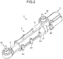
- FIG. 2 is a perspective view of an extension-retraction link of the embodiment.
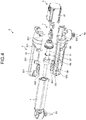
- FIG. 3 is an exploded perspective view of the extension-retraction link of the embodiment.
- FIG. 4 is another exploded perspective view of the extension-retraction link of the embodiment.
- FIG. 5 is a plan view of the extension-retraction link of the embodiment.
- FIG. 6 is a cross sectional view taken along A-A in FIG. 5 .
- the extension-retraction link 2 is a member that connects the vehicle body side member 18 and the hub carrier 19. As illustrated in FIG. 1 , two extension-retraction links 2 are arranged on an upper side of the rotation axis of the wheel 102. Three extension-retraction links 2 are arranged on a lower side of the rotation axis of the wheel 102. As illustrated in FIG. 2 , the extension-retraction link 2 includes a stationary shaft 3, a movable shaft 4, a first universal joint 6a, a second universal joint 6b, and an actuator 5.
- the stationary shaft 3 is connected to the vehicle body side member 18 (refer to FIG. 1 ) with the first universal joint 6a interposed therebetween.
- the stationary shaft 3 has a tubular shape.
- the stationary shaft 3 includes a first member 31 and a second member 32.
- the first member 31 and the second member 32 are connected to each other with fastener members 301.
- two positioning pins 302 are used.
- the first universal joint 6a is attached to the first member 31.
- the movable shaft 4 is connected to the hub carrier 19 (refer to FIG. 1 ) with the second universal joint 6b interposed therebetween.
- the movable shaft 4 is a hollow member having an internal space 40. Part of the movable shaft 4 is located inside the stationary shaft 3.
- the movable shaft 4 can slide with respect to the stationary shaft 3.
- the slidable length of the movable shaft 4 is limited by a stopper 45 (refer to FIG. 6 ) provided to the movable shaft 4.
- the stopper 45 is disposed in a groove 315 provided on an inner circumferential surface of the first member 31. When the stopper 45 reaches the end of the groove 315, the stopper 45 is in contact with the first member 31, thereby stopping the movable shaft 4. This prevents the movable shaft 4 from dropping off from the stationary shaft 3.
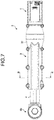
- FIG. 7 is a bottom view of the extension-retraction link in the embodiment.
- FIG. 8 is a cross-sectional view taken along B-B in FIG. 7 .
- FIG. 9 is an exploded perspective view of the stationary shaft in the embodiment.
- the movable shaft 4 includes, as surfaces facing the stationary shaft 3, a first plane surface 41, a second plane surface 42, a third plane surface 43, and a fourth plane surface 44.
- the first plane surface 41 and the second plane surface 42 face the first member 31.
- the second plane surface 42 makes an angle with respect to the first plane surface 41.
- An angle ⁇ made between the first plane surface 41 and the second plane surface 42 is an acute angle.
- the third plane surface 43 and the fourth plane surface 44 face the second member 32.
- the fourth plane surface 44 makes an angle with respect to the third plane surface 43.
- An angle ⁇ made between the third plane surface 43 and the fourth plane surface 44 is an acute angle.
- the third plane surface 43 is in parallel with the first plane surface 41
- the fourth plane surface 44 is in parallel with the second plane surface 42. Accordingly, the angle ⁇ is equal to the angle ⁇ .
- the cross-sectional surface of the movable shaft 4 which is obtained by cutting the movable shaft 4 with a plane perpendicular to a rotation axis Z, has an octagonal shape having four pairs of parallel sides.
- the rotation axis Z is the rotation axis of a screw shaft 57, which is described later. That is, the rotation axis Z is a straight line passing through the gravity center of each cross-sectional surface when the screw shaft 57 is cut with a plane perpendicular to the extending direction of the screw shaft 57.
- the direction parallel with the rotation axis Z is described as an axial direction.
- the direction perpendicular to the rotation axis Z is described as a radius direction.
- the first member 31 includes a first facing surface 311, a second facing surface 312, a first bush 351, and a second bush 352.
- the first facing surface 311 faces the first plane surface 41 of the movable shaft 4.
- the second facing surface 312 faces the second plane surface 42 of the movable shaft 4.
- the first facing surface 311 is in parallel with the first plane surface 41, while the second facing surface 312 is in parallel with the second plane surface 42.
- the first bush 351 which is formed in a plate shape, is fitted in a recess 311d provided on the first facing surface 311.
- the thickness of the first bush 351 is larger than the depth of the recess 311d.
- the first bush 351 is in contact with the first plane surface 41.
- the second bush 352 which is formed in a plate shape, is fitted in a recess 312d provided on the second facing surface 312.
- the thickness of the second bush 352 is larger than the depth of the recess 312d.
- the second bush 352 is in contact with the second plane surface 42.
- the second member 32 includes a third facing surface 323, a fourth facing surface 324, a third bush 353, a fourth bush 354, a first elastic member 363, and a second elastic member 364.
- the third facing surface 323 faces the third plane surface 43 of the movable shaft 4.
- the fourth facing surface 324 faces the fourth plane surface 44 of the movable shaft 4.
- the third facing surface 323 is in parallel with the third plane surface 43, while the fourth facing surface 324 is in parallel with the fourth plane surface 44.
- the third bush 353, which is formed in a plate shape, is fitted in a recess 323d provided on the third facing surface 323.
- the third bush 353 is in contact with the third plane surface 43.
- the first elastic member 363 is a disc spring, for example.
- the first elastic member 363 is disposed between the bottom surface of the recess 323d and the third bush 353.
- the first elastic member 363 presses the third bush 353 to the third plane surface 43.
- the fourth bush 354, which is formed in a plate shape, is fitted in a recess 324d provided on the fourth facing surface 324.
- the fourth bush 354 is in contact with the fourth plane surface 44.
- the second elastic member 364 is a disc spring, for example.
- the second elastic member 364 is disposed between the bottom surface of the recess 324d and the fourth bush 354.
- the second elastic member 364 presses the fourth bush 354 to the fourth plane surface 44.
- the connected portion of the first universal joint 6a and the vehicle body side member 18, and the connected portion of the second universal joint 6b and the hub carrier 19 are located on the same side with respect to a plane including the rotation axis Z of the screw shaft 57, and are on the opposite side of the third bush 353 and the fourth bush 354.
- Each of the connected portion of the first universal joint 6a and the vehicle body side member 18, and the connected portion of the second universal joint 6b and the hub carrier 19 is a fastening portion 611, which is described later.
- the plane including the rotation axis Z of the screw shaft 57 is, for example, a plane PZ illustrated in FIG. 8 .
- each of the first bush 351, the second bush 352, the third bush 353, and the fourth bush 354 includes a plurality of lubricant grooves 35d.
- the lubricant grooves 35d are filled with lubricant.
- the lubricant is grease, for example.
- the first bush 351 includes the lubricant grooves 35d that open on the first plane surface 41 side.
- the second bush 352 includes the lubricant grooves 35d that open on the second plane surface 42 side.
- the third bush 353 includes the lubricant grooves 35d that open on the recess 323d side.
- the fourth bush 354 includes the lubricant grooves 35d that open on the recess 324d side.
- the angles ⁇ and ⁇ illustrated in FIG. 8 are not necessarily acute angles.
- the third plane surface 43 may not be in parallel with the first plane surface 41.
- the fourth plane surface 44 may not be in parallel with the second plane surface 42.
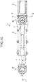
- FIG. 10 is another plan view of the extension-retraction link of the embodiment.
- FIG. 11 is a cross-sectional view taken along C-C in FIG. 10 .
- FIG. 12 is an exploded perspective view of the universal joint in the embodiment.
- the first universal joint 6a is attached to the first member 31 of the stationary shaft 3.
- the first universal joint 6a connects the stationary shaft 3 to the vehicle body side member 18 (refer to FIG. 1 ) such that the stationary shaft 3 can rotate and swing with respect to the vehicle body side member 18.
- the second universal joint 6b is attached to the movable shaft 4.
- the second universal joint 6b connects the movable shaft 4 to the hub carrier 19 (refer to FIG. 1 ) such that the movable shaft 4 can rotate and swing with respect to the hub carrier 19.
- rotation means rotation around a straight line L1 (refer to FIG.
- the straight line L1 is the straight line passing through the gravity center of each cross-sectional surface when an arm 61, which is described later, is cut with a plane perpendicular to the longitudinal direction of the arm 61.
- the straight line L2 is perpendicular to a circle formed by an outer shape of an external bush 63, which is described later, and passes through the center of the circle.
- An intersection M (refer to FIG. 11 ) of the straight lines L1 and L2 is the center of an arm convex surface 617p having a spherical surface shape, which is described later.
- the first universal joint 6a and the second universal joint 6b have the same structure.
- the second universal joint 6b is described as an example. The description of the second universal joint 6b can also be applied to that of the first universal joint 6a.
- the second universal joint 6b includes a housing 60, the arm 61, the external bush 63, an internal bush 65, elastic members 67, and a supporting member 69.
- the housing 60 is formed integrally with the end portion of the movable shaft 4.
- the housing 60 has a tubular shape.
- the housing 60 of the first universal joint 6a is formed integrally with the first member 31.
- the arm 61 is the member connected to the hub carrier 19 (refer to FIG. 1 ).
- the arm 61 is made of metal.
- the metal used for the arm 61 is steel, for example.
- part of the arm 61 is located inside the housing 60.
- the arm 61 includes the fastening portion 611, a flange portion 613, an intermediate portion 615, and a sliding portion 617.
- the fastening portion 611 and the flange portion 613 are located outside the housing 60.
- the fastening portion 611 is a columnar member having a thread on its outer circumferential surface.
- the flange portion 613 is a member that is located on the housing 60 side of the fastening portion 611 and has a substantially conical shape in which the diameter of the flange portion 613 increases toward the housing 60.
- the intermediate portion 615 is a member that extends on the housing 60 side from the flange portion 613 and has a substantially columnar shape.
- the intermediate portion 615 has two parallel flat surfaces on its outer circumferential surface.
- the sliding portion 617 is a member that is located on the housing 60 side of the intermediate portion 615 and has a substantially hemispherical shape.
- the sliding portion 617 includes the arm convex surface 617p, an arm concave surface 617q, and an arm end surface 617e.
- the arm convex surface 617p is the external surface of the sliding portion 617 and has a spherical surface shape.
- the arm concave surface 617q is the internal surface of the sliding portion 617 and has a spherical surface shape.
- the center of the arm concave surface 617q is the same as the center of the arm convex surface 617p.
- the arm end surface 617e is the end surface of the sliding portion 617 that connects the arm convex surface 617p and the arm concave surface 617q. Part of the arm end surface 617e is formed in a conical surface shape.
- the external bush 63 is an annular member located between the inner circumferential surface of the housing 60 and the arm 61.
- the external bush 63 is formed of metal.
- the metal used for the external bush 63 is brass, for example.
- the external bush 63 is press-fitted into the housing 60.
- the external bush 63 includes a bush concave surface 63q serving as its inner circumferential surface.
- the bush concave surface 63q has a spherical surface shape and is in contact with the arm convex surface 617p.
- the center and the radius of the bush concave surface 63q are the same as those of the arm convex surface 617p.
- the internal bush 65 is located inside the sliding portion 617 of the arm 61.
- the internal bush 65 is located on the opposite side of the external bush 63 with respect to the sliding portion 617.
- the internal bush 65 is formed of metal.
- the metal used for the internal bush 65 is brass, for example.
- the internal bush 65 includes a head portion 651 and a body portion 653.
- the head portion 651 has a substantially hemispherical shape and a bush convex surface 651p.
- the bush convex surface 651p is a spherical surface and in contact with the arm concave surface 617q.
- the sliding portion 617 is sandwiched between the bush convex surface 651p of the internal bush 65 and the bush concave surface 63q of the external bush 63.
- the center and the radius of the bush convex surface 651p are the same as those of the arm concave surface 617q.
- the body portion 653 is a substantially cylindrical member extending from the head portion 651 toward the opposite side of the bush convex surface 651p.
- the supporting member 69 supports the internal bush 65. As illustrated in FIG. 11 , the supporting member 69 is attached inside the housing 60.
- the supporting member 69 is formed of metal.
- the metal used for the supporting member 69 is steel, for example.
- the supporting member 69 includes a male screw 691, a first recess 693, and a second recess 695.
- the male screw 691 engages with a female screw 601 provided to the housing 60.
- the first recess 693 is a dent that opens toward the internal bush 65 and has a truncated cone shape.
- the bottom surface of the first recess 693 is a plane perpendicular to the extending direction of the body portion 653 of the internal bush 65.
- the second recess 695 is a dent that is provided on the bottom surface of the first recess 693 and has a columnar shape.
- the body portion 653 is fitted in the second recess 695 and guided by the inner circumferential surface of the second recess 695.
- the elastic members 67 are located between the internal bush 65 and the supporting member 69 and press the internal bush 65 toward the arm 61.
- the elastic member 67 is a disc spring, for example.
- Two elastic members 67 are arranged overlapping with each other between the body portion 653 and the bottom surface of the second recess 695.
- the inside of the housing 60 is filled with lubricant.
- the lubricant is grease, for example.
- the sliding portion 617 of the arm 61 can move along the external bush 63 and the internal bush 65. Accordingly, the arm 61 can rotate and swing relatively with respect to the external bush 63 and the internal bush 65. As illustrated in FIG. 11 , the arm end surface 617e is in contact with the bottom surface of the first recess 693. When the arm end surface 617e is in contact with the bottom surface of the first recess 693, a gap 60c is formed between the arm 61 and the housing 60.
- the materials used for the respective first universal joint 6a and second universal joint 6b are not limited to those described above.
- the number of elastic members 67 included in the first universal joint 6a and the second universal joint 6b is not limited to any specific number. The number may be one or three or more.
- the first universal joint 6a and the second universal joint 6b do not necessarily have the same structure.
- the first universal joint 6a and the second universal joint 6b are not necessarily used for the extension-retraction link 2.
- the extension-retraction link 2 is an example of objects to which the first universal joint 6a and the second universal joint 6b are applied.
- the first universal joint 6a and the second universal joint 6b can be applied to a part other than the suspension 1 of the vehicle 10 and can also be applied to an apparatus other than the vehicle 10.
- the actuator 5 includes a motor 51, the screw shaft 57, a bearing unit 55, a nut 59, a snap ring 58, and a clutch 7.
- the motor 51 is disposed at the end portion of the stationary shaft 3 on the opposite side of the movable shaft 4.
- the motor 51 is fixed to the stationary shaft 3.
- the motor 51 includes an encoder that detects a rotation angle of a rotor.
- a shaft 511 that rotates together with the rotor of the motor 51 extends toward the inside of the stationary shaft 3.
- the screw shaft 57 is connected to the shaft 511 with the clutch 7 interposed therebetween.
- the screw shaft 57 rotates together with the shaft 511 around the rotation axis Z serving as the rotation center. Part of the screw shaft 57 is inserted into the movable shaft 4. The end of the screw shaft 57 is located in the internal space 40 of the movable shaft 4.
- the screw shaft 57 passes through the nut 59.
- the bearing unit 55 supports the screw shaft 57 such that the screw shaft 57 can rotate with respect to the stationary shaft 3.
- the bearing unit 55 is fixed to the stationary shaft 3 and has bearings 551 built-in.
- the bearings 551 are fitted in the outer circumferential surface of the screw shaft 57.
- the nut 59 is fixed to the movable shaft 4 with the snap ring 58 and moves together with the movable shaft 4.
- the nut 59 includes two protrusions 591 protruding in the radius direction.
- the protrusions 591 are fitted in a recess 49 provided on the end surface of the movable shaft 4. This restricts the rotation of the nut 59.
- the snap ring 58 is fitted in a substantially annular groove provided on the inner circumferential surface of the movable shaft 4 and positions the nut 59 in the axial direction.
- FIG. 13 is a cross-sectional view taken along D-D in FIG. 10 .
- FIG. 14 is an exploded perspective view of the clutch in the embodiment.
- the clutch 7 includes an input side member 71, a first brake shoe 73, a second brake shoe 75, a brake drum 77, an engagement element 79, and elastic members 74.
- the input side member 71 which is a member having a substantially cylindrical shape, is attached to the shaft 511.
- the input side member 71 includes a key groove 715, a main body 710, a first pin 711, and a second pin 712.
- the main body 710 has a substantially cylindrical shape along the shaft 511, and includes the key groove 715.
- the shaft 511 includes a key 515 that is a protrusion extending in the axial direction.
- the key 515 fits in the key groove 715. Accordingly, the input side member 71 rotates together with the shaft 511.
- the first pin 711 and the second pin 712 protrude from the end surface of the main body 710 toward the screw shaft 57 side.
- the second pin 712 is disposed on the opposite side of the first pin 711 with respect to the rotation axis Z.
- the outside surface in the radius direction of the first pin 711 is a circular arc.
- the inside surface in the radius direction of the first pin 711 is a plane.
- the outer shape of the second pin 712 and the outer shape of the first pin 711 are point-symmetric about the rotation axis Z.
- the first brake shoe 73 is a substantially semicircular columnar member.
- the first brake shoe 73 includes a first fitting portion 730, a first engagement groove 731, and two first elastic member grooves 733.
- the first fitting portion 730 is a hole penetrating in the axial direction.
- the first fitting portion 730 is also described as a first hole.
- the first pin 711 fits in the first fitting portion 730.
- the first engagement groove 731 and the first elastic member grooves 733 are grooves provided on the surface on the second brake shoe 75 side.
- the first engagement groove 731 is disposed between the two first elastic member grooves 733.
- the first engagement groove 731 has a length corresponding to the entire length of the first brake shoe 73 in the axial direction.
- the first elastic member grooves 733 are arranged at the center of the first brake shoe 73 in the axial direction.
- the first fitting portion 730 is not necessarily a hole, and may be a recess, for example..
- the second brake shoe 75 is a substantially semicircular columnar member.
- the second brake shoe 75 includes a second fitting portion 750, a second engagement groove 751, and two second elastic member grooves 753.
- the second fitting portion 750 is a hole penetrating in the axial direction.
- the second fitting portion 750 is also described as a second hole.
- the second pin 712 fits in the second fitting portion 750.
- the second engagement groove 751 and the second elastic member grooves 753 are the grooves provided on the surface on the first brake shoe 73 side.
- the second engagement groove 751 is disposed between the two second elastic member grooves 753.
- the second engagement groove 751 has a length corresponding to the entire length of the second brake shoe 75 in the axial direction.
- the second elastic member grooves 753 are arranged at the center of the second brake shoe 75 in the axial direction.
- the second fitting portion 750 is not necessarily a hole, and may be a recess, for example.
- a gap having an oval shape when viewed from the axial direction is formed by the first engagement groove 731 and the second engagement groove 751.
- a columnar gap is formed by each of the first elastic member groove 733 and the second elastic member groove 753.
- the brake drum 77 is a member that puts a brake on the first brake shoe 73 and the second brake shoe 75.
- the brake drum 77 includes a base 771 and two arms 773.
- the base 771 has a cylindrical shape having a hole 770.
- the first brake shoe 73 and the second brake shoe 75 are inserted into the hole 770.
- the inner circumferential surface of the base 771 faces the outer circumferential surface of the first brake shoe 73 and the outer circumferential surface of the second brake shoe 75.
- the arm 773 is a plate-like member protruding from the outer circumferential surface of the base 771.
- the two arms 773 extend in mutually opposite directions.
- the arms 773 fit in recesses 327 provided to the second member 32 illustrated in FIG. 14 .
- the arms 773 are sandwiched by the first member 31 and the second member 32, resulting in the brake drum 77 being fixed to the stationary shaft 3. This prevents the brake drum 77 from rotating.
- the engagement element 79 which is attached to the screw shaft 57, rotates together with the screw shaft 57. As illustrated in FIG. 13 , the engagement element 79 viewed from the axial direction has an oval shape. The engagement element 79 fits in a gap formed by the first engagement groove 731 and the second engagement groove 751.
- the elastic member 74 is a helical compression spring, for example.
- the elastic member 74 is disposed in a gap formed by the first elastic member groove 733 and the second elastic member groove 753.
- the elastic members 74 apply force to the first brake shoe 73 and the second brake shoe 75 in such a direction that the first brake shoe 73 and the second brake shoe 75 separate from each other.
- the input side member 71 rotates together with the shaft 511.
- the rotation of the first pin 711 and the second pin 712 of the input side member 71 applies force to the first brake shoe 73 and the second brake shoe 75 in such a direction that the first brake shoe 73 and the second brake shoe 75 approach each other.
- the engagement element 79 is held by the first brake shoe 73 and the second brake shoe 75.
- the integral rotation of the first brake shoe 73, the second brake shoe 75, and the engagement element 79 causes the rotation of the shaft 511 to be transmitted to the screw shaft 57.
- the external force applied to the movable shaft 4 at the time of stoppage of the motor 51 is, for example, external force transmitted to the movable shaft 4 in a case where the wheel 102 touches a curbstone or the like when the vehicle 10 is being parked. External force received by the wheel 102 from the curb or the like is transmitted to the movable shaft 4, thereby causing the screw shaft 57 to rotate.
- the clutch 7 does not necessarily include the elastic members 74. In such a case, the first elastic member grooves 733 and the second elastic member grooves 753 may be omitted.
- the engagement element 79 viewed from the axial direction does not necessarily have an oval shape, and is only required to have a shape other than a circular shape. A distance from the rotation axis Z to the outer circumferential surface of the engagement element 79 is only required to be not constant.
- the controller 9 illustrated in FIG. 1 is a computer, which includes, for example, a central processing unit (CPU), a read only memory (ROM), a random access memory (RAM), an input interface, and an output interface.
- the controller 9 is an electronic control unit (ECU) mounted on the vehicle 10, for example.
- the controller 9 is electrically connected to the motors 51 of the respective extension-retraction links 2.
- the controller 9 controls the motors 51 individually. As a result, the length of each extension-retraction link 2 (position of the movable shaft 4) changes.
- the suspension 1 in the embodiment includes five extension-retraction links 2 for each wheel 102.
- the suspension 1 can change a toe angle, a camber angle, a caster angle, a tread width, and a wheelbase by changing the length of each extension-retraction link 2.
- the toe angle is, when the vehicle 10 is viewed from the vertical direction, an angle made by a straight line perpendicular to the rotation axis of the wheel 102 with respect to the straight line parallel with the front-rear direction of the vehicle.
- the camber angle is, when the vehicle 10 is viewed from the front-rear direction, an angle made by the straight line perpendicular to the rotation axis of the wheel 102 with respect to the vertical line.
- the caster angle is, when the vehicle 10 is viewed from the horizontal direction, an angle made by a straight line parallel with the longitudinal direction of the shock absorber 11 with respect to the vertical line.
- the tread width is a distance between the centers of the left and right wheels 102.
- the wheelbase is a distance between the centers of the front and rear wheels 102.
- the suspension 1 is not necessarily applied to vehicles with the hub units 101 having motors and the like built-in.
- the suspension 1 may be connected to the hub carrier including a hub bearing supporting the wheel 102.
- the suspension 1 does not necessarily include five extension-retraction links 2.
- the suspension 1 is only required to include a plurality of links, at least one of which should be the extension-retraction link 2.
- the suspension 1 includes a plurality of links that connect the vehicle body side member 18 and the hub carrier 19. At least one of the links is the extension-retraction link 2.
- the extension-retraction link 2 includes: the stationary shaft 3; the first universal joint 6a that connects the stationary shaft 3 to the vehicle body side member 18 such that the stationary shaft 3 can rotate and swing with respect to the vehicle body side member 18; the movable shaft 4 that can slide with respect to the stationary shaft 3; the second universal joint 6b that connects the movable shaft 4 to the hub carrier 19 such that the movable shaft 4 can rotate and swing with respect to the hub carrier 19; and the actuator 5 that is fixed to the stationary shaft 3 and moves the movable shaft 4.
- the suspension 1 can change the posture of the wheel 102 by moving the movable shaft 4.
- the suspension 1 can easily change the relative posture of the wheel 102 with respect to the vehicle body.
- the suspension 1 includes five extension-retraction links 2.
- the suspension 1 can change the toe angle, the camber angle, the caster angle, the tread width, and the wheelbase by moving the movable shaft 4.
- the suspension 1 can easily change the relative posture of the wheel 102 with respect to the vehicle body.
- the extension-retraction link 2 includes: the tubular stationary shaft 3; the first universal joint 6a that connects the stationary shaft 3 to the vehicle body side member 18 such that the stationary shaft 3 can rotate and swing with respect to the vehicle body side member 18; the movable shaft 4, part of which is located inside the stationary shaft 3 and that can slide with respect to the stationary shaft 3; the second universal joint 6b that connects the movable shaft 4 to the hub carrier 19 such that the movable shaft 4 can rotate and swing with respect to the hub carrier 19; and the actuator 5.
- the actuator 5 includes: the motor 51 attached to the stationary shaft 3; the screw shaft 57 rotated by the motor 51; and the nut 59 that engages with the screw shaft 57 and is fixed to the movable shaft 4.
- the movable shaft 4 includes: the first plane surface 41; the second plane surface 42 making an angle with respect to the first plane surface 41; the third plane surface 43 located on the opposite side of the first plane surface 41; and the fourth plane surface 44 located on the opposite side of the second plane surface 42.
- the stationary shaft 3 includes: the first bush 351 in contact with the first plane surface 41; the second bush 352 in contact with the second plane surface 42; the third bush 353 in contact with the third plane surface 43; the fourth bush 354 in contact with the fourth plane surface 44; the first elastic member 363 pressing the third bush 353 to the third plane surface 43; and the second elastic member 364 pressing the fourth bush 354 to the fourth plane surface 44.
- the movement of the movable shaft 4 connected to the hub carrier 19 enables the posture of the wheel 102 to change.
- the extension-retraction link 2 can easily change the relative posture of the wheel 102 with respect to the vehicle body.
- first elastic member 363 and the second elastic member 364 can maintain a state where the first bush 351, the second bush 352, the third bush 353, and the fourth bush 354 are in contact with the movable shaft 4. This prevents backlash of the movable shaft 4 without requiring high machining accuracy.
- the extension-retraction link 2 can make the movement of the movable shaft 4 smooth.
- the connected portion (fastening portion 611) of the first universal joint 6a with the vehicle body side member 18, and the connected portion (fastening portion 611) of the second universal joint 6b with the hub carrier 19 are located on the same side with respect to the plane (e.g., the plane PZ illustrated in FIG. 8 ) including the rotation axis Z of the screw shaft 57, and on the opposite side of the third bush 353 and the fourth bush 354.
- the plane e.g., the plane PZ illustrated in FIG. 8
- the positional relation among the stationary shaft 3, the first universal joint 6a, the movable shaft 4, and the second universal joint 6b causes force toward the first bush 351 and the second bush 352 to act on the movable shaft 4 with the movement of the movable shaft 4.
- the first elastic member 363 and the second elastic member 364 make it harder for a gap to be formed in the gap between the third bush 353 and the third plane surface 43 and the gap between the fourth bush 354 and the fourth plane surface 44. Accordingly, the extension-retraction link 2 can prevent backlash of the movable shaft 4 even when force in the radius direction is applied to the movable shaft 4.
- the angle ⁇ made between the first plane surface 41 and the second plane surface 42 and the angle ⁇ made between the third plane surface 43 and the fourth plane surface 44 are acute angles.
- the movable shaft 4 may be deformed by a wheel load and the like received by the wheel 102 while the vehicle 10 is moving (especially while turning).
- the movable shaft 4 may be deformed around an axis that is in parallel with the plane PZ illustrated in FIG. 8 and perpendicular to the rotation axis Z (around the axis in parallel with the upper and lower direction in FIG. 8 ).
- a section modulus of the movable shaft 4 about the axis when the angles ⁇ and ⁇ are acute angles is larger than that when the angles ⁇ and ⁇ are obtuse angles. Accordingly, stiffness of the movable shaft 4 with respect to a moment applied to the movable shaft 4 increases. This prevents deformation of the movable shaft 4, thereby making the movement of the movable shaft 4 smoother.
- each of the first bush 351, the second bush 352, the third bush 353, and the fourth bush 354 includes multiple lubricant grooves 35d filled with lubricant.
- angles ⁇ and ⁇ are acute angles, thereby preventing deformation of the movable shaft 4. As a result, lubricant surrounding the movable shaft 4 is applied on the movable shaft 4.
- the suspension 1 including the extension-retraction link 2 can make the movement of the wheel 102 smooth by the movable shaft 4, the backlash of which is prevented.
- the universal joint (the first universal joint 6a or the second universal joint 6b) includes: the housing 60; the arm 61, part of which is located inside the housing 60; the external bush 63 located between the inner circumferential surface of the housing 60 and the arm 61; the internal bush 65 located on the opposite side of the external bush 63 with the arm 61 interposed therebetween; and the supporting member 69 supporting the internal bush 65.
- the arm 61 includes: the arm convex surface 617p that is a spherical convex surface; and the arm concave surface 617q that is a spherical concave surface.
- the external bush 63 includes the bush concave surface 63q that is a spherical concave surface in contact with the arm convex surface 617p.
- the internal bush 65 includes the bush convex surface 651p that is a spherical convex surface in contact with the arm concave surface 617q.
- the increase of a movable range and a permissible load requires the increase of the diameter of the ball.
- the universal joint (the first universal joint 6a or the second universal joint 6b) in the embodiment
- the arm 61 is sandwiched and held by the bush concave surface 63q of the external bush 63 and the bush convex surface 651p of the internal bush 65. Accordingly, a contact area between the arm 61 and the external bush 63 and a contact area between the arm 61 and the internal bush 65 can be easily maintained constant, thereby increasing the permissible load of the universal joint. Consequently, the universal joint is smaller than the ball joint even when the movable range and the permissible load are increased. Therefore, the universal joint can easily increase the movable range and achieve a compact size.
- the universal joint (the first universal joint 6a or the second universal joint 6b) includes the elastic members 67 that push the internal bush 65 toward the arm 61.
- the arm 61 includes the arm end surface 617e located between the arm convex surface 617p and the arm concave surface 617q.
- the gap 60c is present between the arm 61 and the housing 60.
- the housing 60 includes the female screw 601.
- the supporting member 69 includes the male screw 691 engaging with the female screw 601. That is, the supporting member 69 is fixed to the housing 60 by the engagement of the male screw 691 with the female screw 601.
- At least one of the first universal joint 6a and the second universal joint 6b is the universal joint described above.
- first universal joint 6a or the second universal joint 6b This allows the first universal joint 6a or the second universal joint 6b to have a wide movable range, thereby allowing the extension-retraction link 2 to easily change the relative posture of the wheel 102 with respect to the vehicle body.
- the universal joint (the first universal joint 6a or the second universal joint 6b) has a compact size, thereby allowing the suspension 1 to have a plurality of universal joints arranged close to one another. Accordingly, the suspension 1 can include the multiple extension-retraction links 2, thereby allowing the wheel 102 to easily change its relative posture with respect to the vehicle body.
- the actuator 5 includes: the motor 51 attached to the stationary shaft 3; the screw shaft 57 rotated by the motor 51; the clutch 7 disposed between the motor 51 and the screw shaft 57; and the nut 59 that engages with the screw shaft 57 and is fixed to the movable shaft 4.
- the clutch 7 includes the input side member 71, the first brake shoe 73, the second brake shoe 75, the brake drum 77, and the engagement element 79.
- the input side member 71 rotates together with the shaft 511 of the motor 51 and has the first pin 711 and the second pin 712.
- the first brake shoe 73 has the first fitting portion 730, in which the first pin 711 fits.
- the second brake shoe 75 has the second fitting portion 750, in which the second pin 712 fits, and is located on the opposite side of the first brake shoe 73 with respect to the rotation axis Z of the screw shaft 57.
- the brake drum 77 has the inner circumferential surface facing the outer circumferential surfaces of the first brake shoe 73 and the second brake shoe 75 and is fixed to the stationary shaft 3. It rotates together with the screw shaft 57 and fits in the gap between the first brake shoe 73 and the second brake shoe 75.
- the extension-retraction link 2 can change the posture of the wheel 102 by moving the movable shaft 4.
- the extension-retraction link 2 can easily change the relative posture of the wheel 102 with respect to the vehicle body.
- force is applied by the engagement element 79 in such a direction that the first brake shoe 73 and the second brake shoe 75 separate from each other. This causes the first brake shoe 73 and the second brake shoe 75 to be pressed to the brake drum 77, thereby preventing the rotation of the engagement element 79 and the screw shaft 57. In this way, even when external force is applied to the movable shaft 4 at the time of stoppage of the motor 51, the movement of the movable shaft 4 is restricted.
- the extension-retraction link 2 can easily maintain the relative posture of the wheel 102 with respect to the vehicle body. When the position of the movable shaft 4 is maintained, no electric power supply to the motor 51 is required. Accordingly, the extension-retraction link 2 can reduce power consumption.
- the extension-retraction link 2 includes the elastic members 74 that apply force in such a direction that the first brake shoe 73 and the second brake shoe 75 separate from each other.
- the elastic members 74 press the first brake shoe 73 and the second brake shoe 75 to the brake drum 77. Consequently, the extension-retraction link 2 can prevent backlash of the first brake shoe 73 due to the gap between the engagement element 79 and the first brake shoe 73, and backlash of the second brake shoe 75 due to the gap between the engagement element 79 and the second brake shoe 75.
- the suspension 1 including the actuator 5 has the clutch 7, thereby reducing the power consumption of the vehicle.
Abstract
Description
- The present invention relates to an extension-retraction link and a suspension.
- A vehicle has a suspension provided between its body and a wheel. The suspension is a device that makes vibrations due to fluctuation of a road surface less likely to be transmitted to the vehicle body, and that positions the wheel. A multi-link suspension is known as one of suspension types. Patent Literature 1, for example, describes an example of the multi-link suspension.
- Patent Literature 1: Japanese Laid-open Patent Publication No.
2015-155255 - In some cases, a relative posture of the wheel with respect to the vehicle body is required to be changed in accordance with motion performance required for the vehicle.
- The present disclosure has been made in view of the above, and aims to provide an extension-retraction link that can easily change a relative posture of the wheel with respect to the vehicle body.
- To achieve the purpose described above, an extension-retraction link according to an aspect of the present disclosure includes: a stationary shaft having a tubular shape; a first universal joint that connects the stationary shaft to a vehicle body side member such that the stationary shaft is capable of rotating and swinging with respect to the vehicle body side member; a movable shaft, part of which is located inside the stationary shaft, and that is capable of sliding with respect to the stationary shaft; a second universal joint that connects the movable shaft to a hub carrier such that the movable shaft is capable of rotating and swinging with respect to the hub carrier; and an actuator that includes: a motor attached to the stationary shaft; a screw shaft rotated by the motor; and a nut that engages with the screw shaft and is fixed to the movable shaft. The movable shaft includes: a first plane surface; a second plane surface making an angle with respect to the first plane surface; a third plane surface located on the opposite side of the first plane surface; and a fourth plane surface located on the opposite side of the second plane surface. The stationary shaft includes: a first bush in contact with the first plane surface; a second bush in contact with the second plane surface; a third bush in contact with the third plane surface; a fourth bush in contact with the fourth plane surface; a first elastic member pressing the third bush to the third plane surface; and a second elastic member pressing the fourth bush to the fourth plane surface.
- Accordingly, the extension-retraction link can change the posture of the wheel by moving the movable shaft. The extension-retraction link can easily change the relative posture of the wheel with respect to the vehicle body.
- Further, the first elastic member and the second elastic member maintain the state where the first bush, the second bush, the third bush, and the fourth bush are in contact with the movable shaft. This can prevent backlash of the movable shaft without high machining accuracy. The extension-retraction link can make the movement of the movable shaft smooth.
- As a preferred aspect of the extension-retraction link, a connected portion of the first universal joint and the vehicle body side member and a connected portion of the second universal joint and the hub carrier are located on an identical side with respect to a plane including a rotation axis of the screw shaft, and are located on the opposite side of the third bush and the fourth bush.
- The positional relation among the stationary shaft, the first universal joint, the movable shaft, and the second universal joint causes force toward the first bush and the second bush to act on the movable shaft with the movement of the movable shaft. Even in such a case, a gap becomes harder to be formed in the gap between the third bush and the third plane surface and the gap between the fourth bush and the fourth plane surface. Accordingly, the extension-retraction link can prevent backlash of the movable shaft even when force in the radius direction is applied to the movable shaft.
- As a preferred aspect of the extension-retraction link, the angle made between the first plane surface and the second plane surface and the angle made between the third plane surface and the fourth plane surface are acute angles.
- Accordingly, stiffness of the movable shaft with respect to a moment applied to the movable shaft increases. This prevents deformation of the movable shaft, and makes the movement of the movable shaft smoother.
- As a preferred aspect of the extension-retraction link, each of the first bush, the second bush, the third bush, and the fourth bush includes a plurality of lubricant grooves, in which lubricant is filled.
- This makes it harder for lubricant surrounding the movable shaft to be exhausted, thereby making the movement of the movable shaft smoother.
- A suspension according to another aspect of the present disclosure includes the extension-retraction link.
- The extension-retraction link of the suspension can easily change the relative posture of the wheel with respect to the vehicle body. Further, the suspension makes the movement of the wheel smooth by the movable shaft, backlash of which is prevented.
- The present disclosure can provide the extension-retraction link that can easily change the relative posture of the wheel with respect to the vehicle body.
-
-
FIG. 1 is a perspective view of a suspension in an embodiment. -
FIG. 2 is a perspective view of an extension-retraction link in the embodiment. -
FIG. 3 is an exploded perspective view of the extension-retraction link in the embodiment. -
FIG. 4 is another exploded perspective view of the extension-retraction link in the embodiment. -
FIG. 5 is a plan view of the extension-retraction link in the embodiment. -
FIG. 6 is a cross-sectional view taken along A-A inFIG. 5 . -
FIG. 7 is a bottom view of the extension-retraction link in the embodiment. -
FIG. 8 is a cross-sectional view taken along B-B inFIG. 7 . -
FIG. 9 is an exploded perspective view of a stationary shaft in the embodiment. -
FIG. 10 is another plan view of the extension-retraction link in the embodiment. -
FIG. 11 is a cross-sectional view taken along C-C inFIG. 10 . -
FIG. 12 is an exploded perspective view of a universal joint in the embodiment. -
FIG. 13 is a cross-sectional view taken along D-D inFIG. 10 . -
FIG. 14 is an exploded perspective view of a clutch in the embodiment. - The following describes the present invention in detail with reference to the accompanying drawings. The following embodiment for carrying out the invention (hereinafter described as the embodiment) does not limit the invention. The constituent elements in the embodiment described below include elements that can be easily conceived of by a person skilled in the art, elements substantially equivalent thereto, and elements within a so-called range of equivalents. The constituent elements disclosed in the following embodiment can be combined as appropriate.
-
FIG. 1 is a perspective view of a suspension in the embodiment. Avehicle 10 in the embodiment includeswheels 102,hub units 101, vehiclebody side members 18,hub carriers 19, suspensions 1, and a controller 9. For example, thevehicle 10 includes fourwheels 102, each of which includes thehub unit 101. Thehub unit 101 includes a hub bearing, two motors, and a speed changer, for example. Thehub unit 101 rotatably supports thewheel 102 and drives thewheel 102. The vehiclebody side member 18 is fixed to the vehicle body. Thehub carrier 19 is a member fixed to thehub unit 101. Thehub carrier 19 is also called a knuckle. - The suspension 1 is a device that connects the vehicle body (chassis) of the
vehicle 10 and thehub unit 101. The suspension 1 is a multi-link suspension. As illustrated inFIG. 1 , the suspension 1 includes ashock absorber 11 and five extension-retraction links 2 for eachwheel 102. - The
shock absorber 11 is a device that reduces shock transmitted to the vehicle body from a road surface during vehicle running. One end of theshock absorber 11 is fixed to the vehicle body. The other end of theshock absorber 11 is fixed to thehub carrier 19. Theshock absorber 11 can extend and retract in an upper-lower direction. -
FIG. 2 is a perspective view of an extension-retraction link of the embodiment.FIG. 3 is an exploded perspective view of the extension-retraction link of the embodiment.FIG. 4 is another exploded perspective view of the extension-retraction link of the embodiment.FIG. 5 is a plan view of the extension-retraction link of the embodiment.FIG. 6 is a cross sectional view taken along A-A inFIG. 5 . - The extension-
retraction link 2 is a member that connects the vehiclebody side member 18 and thehub carrier 19. As illustrated inFIG. 1 , two extension-retraction links 2 are arranged on an upper side of the rotation axis of thewheel 102. Three extension-retraction links 2 are arranged on a lower side of the rotation axis of thewheel 102. As illustrated inFIG. 2 , the extension-retraction link 2 includes astationary shaft 3, amovable shaft 4, a first universal joint 6a, a second universal joint 6b, and anactuator 5. - The
stationary shaft 3 is connected to the vehicle body side member 18 (refer toFIG. 1 ) with the first universal joint 6a interposed therebetween. Thestationary shaft 3 has a tubular shape. As illustrated inFIGS. 3 and4 , thestationary shaft 3 includes afirst member 31 and asecond member 32. Thefirst member 31 and thesecond member 32 are connected to each other withfastener members 301. When thefirst member 31 and thesecond member 32 are assembled, two positioningpins 302 are used. The first universal joint 6a is attached to thefirst member 31. - The
movable shaft 4 is connected to the hub carrier 19 (refer toFIG. 1 ) with the second universal joint 6b interposed therebetween. As illustrated inFIG. 6 , themovable shaft 4 is a hollow member having aninternal space 40. Part of themovable shaft 4 is located inside thestationary shaft 3. Themovable shaft 4 can slide with respect to thestationary shaft 3. The slidable length of themovable shaft 4 is limited by a stopper 45 (refer toFIG. 6 ) provided to themovable shaft 4. Thestopper 45 is disposed in agroove 315 provided on an inner circumferential surface of thefirst member 31. When thestopper 45 reaches the end of thegroove 315, thestopper 45 is in contact with thefirst member 31, thereby stopping themovable shaft 4. This prevents themovable shaft 4 from dropping off from thestationary shaft 3. -
FIG. 7 is a bottom view of the extension-retraction link in the embodiment.FIG. 8 is a cross-sectional view taken along B-B inFIG. 7 .FIG. 9 is an exploded perspective view of the stationary shaft in the embodiment. - As illustrated in
FIG. 8 , themovable shaft 4 includes, as surfaces facing thestationary shaft 3, afirst plane surface 41, asecond plane surface 42, athird plane surface 43, and a fourth plane surface 44. Thefirst plane surface 41 and thesecond plane surface 42 face thefirst member 31. Thesecond plane surface 42 makes an angle with respect to thefirst plane surface 41. An angle α made between thefirst plane surface 41 and thesecond plane surface 42 is an acute angle. Thethird plane surface 43 and the fourth plane surface 44 face thesecond member 32. The fourth plane surface 44 makes an angle with respect to thethird plane surface 43. An angle β made between thethird plane surface 43 and the fourth plane surface 44 is an acute angle. For example, thethird plane surface 43 is in parallel with thefirst plane surface 41, and the fourth plane surface 44 is in parallel with thesecond plane surface 42. Accordingly, the angle β is equal to the angle α. As illustrated inFIG. 8 , the cross-sectional surface of themovable shaft 4, which is obtained by cutting themovable shaft 4 with a plane perpendicular to a rotation axis Z, has an octagonal shape having four pairs of parallel sides. - The rotation axis Z is the rotation axis of a
screw shaft 57, which is described later. That is, the rotation axis Z is a straight line passing through the gravity center of each cross-sectional surface when thescrew shaft 57 is cut with a plane perpendicular to the extending direction of thescrew shaft 57. In the following description, the direction parallel with the rotation axis Z is described as an axial direction. The direction perpendicular to the rotation axis Z is described as a radius direction. - As illustrated in
FIG. 8 , thefirst member 31 includes a first facingsurface 311, a second facingsurface 312, afirst bush 351, and asecond bush 352. The first facingsurface 311 faces thefirst plane surface 41 of themovable shaft 4. The second facingsurface 312 faces thesecond plane surface 42 of themovable shaft 4. For example, the first facingsurface 311 is in parallel with thefirst plane surface 41, while the second facingsurface 312 is in parallel with thesecond plane surface 42. Thefirst bush 351, which is formed in a plate shape, is fitted in arecess 311d provided on the first facingsurface 311. The thickness of thefirst bush 351 is larger than the depth of therecess 311d. Thefirst bush 351 is in contact with thefirst plane surface 41. Thesecond bush 352, which is formed in a plate shape, is fitted in arecess 312d provided on the second facingsurface 312. The thickness of thesecond bush 352 is larger than the depth of therecess 312d. Thesecond bush 352 is in contact with thesecond plane surface 42. - As illustrated in
FIG. 8 , thesecond member 32 includes a third facingsurface 323, a fourth facingsurface 324, athird bush 353, afourth bush 354, a firstelastic member 363, and a secondelastic member 364. The third facingsurface 323 faces thethird plane surface 43 of themovable shaft 4. The fourth facingsurface 324 faces the fourth plane surface 44 of themovable shaft 4. For example, the third facingsurface 323 is in parallel with thethird plane surface 43, while the fourth facingsurface 324 is in parallel with the fourth plane surface 44. Thethird bush 353, which is formed in a plate shape, is fitted in arecess 323d provided on the third facingsurface 323. Thethird bush 353 is in contact with thethird plane surface 43. The firstelastic member 363 is a disc spring, for example. The firstelastic member 363 is disposed between the bottom surface of therecess 323d and thethird bush 353. The firstelastic member 363 presses thethird bush 353 to thethird plane surface 43. Thefourth bush 354, which is formed in a plate shape, is fitted in arecess 324d provided on the fourth facingsurface 324. Thefourth bush 354 is in contact with the fourth plane surface 44. The secondelastic member 364 is a disc spring, for example. The secondelastic member 364 is disposed between the bottom surface of therecess 324d and thefourth bush 354. The secondelastic member 364 presses thefourth bush 354 to the fourth plane surface 44. - As illustrated in
FIGS. 6 and8 , the connected portion of the first universal joint 6a and the vehiclebody side member 18, and the connected portion of the second universal joint 6b and thehub carrier 19 are located on the same side with respect to a plane including the rotation axis Z of thescrew shaft 57, and are on the opposite side of thethird bush 353 and thefourth bush 354. Each of the connected portion of the first universal joint 6a and the vehiclebody side member 18, and the connected portion of the second universal joint 6b and thehub carrier 19 is afastening portion 611, which is described later. The plane including the rotation axis Z of thescrew shaft 57 is, for example, a plane PZ illustrated inFIG. 8 . - As illustrated in
FIG. 9 , each of thefirst bush 351, thesecond bush 352, thethird bush 353, and thefourth bush 354 includes a plurality oflubricant grooves 35d. Thelubricant grooves 35d are filled with lubricant. The lubricant is grease, for example. Thefirst bush 351 includes thelubricant grooves 35d that open on thefirst plane surface 41 side. Thesecond bush 352 includes thelubricant grooves 35d that open on thesecond plane surface 42 side. Thethird bush 353 includes thelubricant grooves 35d that open on therecess 323d side. Thefourth bush 354 includes thelubricant grooves 35d that open on therecess 324d side. - The angles α and β illustrated in
FIG. 8 are not necessarily acute angles. Thethird plane surface 43 may not be in parallel with thefirst plane surface 41. The fourth plane surface 44 may not be in parallel with thesecond plane surface 42. -
FIG. 10 is another plan view of the extension-retraction link of the embodiment.FIG. 11 is a cross-sectional view taken along C-C inFIG. 10 .FIG. 12 is an exploded perspective view of the universal joint in the embodiment. - As illustrated in
FIG. 10 , the first universal joint 6a is attached to thefirst member 31 of thestationary shaft 3. The first universal joint 6a connects thestationary shaft 3 to the vehicle body side member 18 (refer toFIG. 1 ) such that thestationary shaft 3 can rotate and swing with respect to the vehiclebody side member 18. The second universal joint 6b is attached to themovable shaft 4. The second universal joint 6b connects themovable shaft 4 to the hub carrier 19 (refer toFIG. 1 ) such that themovable shaft 4 can rotate and swing with respect to thehub carrier 19. In the description about the capability of rotation and swing, rotation means rotation around a straight line L1 (refer toFIG. 11 ) serving as the rotation center, while swing means movement by which an angle θ made between the straight line L1 and a straight line L2 changes. The straight line L1 is the straight line passing through the gravity center of each cross-sectional surface when anarm 61, which is described later, is cut with a plane perpendicular to the longitudinal direction of thearm 61. The straight line L2 is perpendicular to a circle formed by an outer shape of anexternal bush 63, which is described later, and passes through the center of the circle. An intersection M (refer toFIG. 11 ) of the straight lines L1 and L2 is the center of an armconvex surface 617p having a spherical surface shape, which is described later. In the embodiment, the first universal joint 6a and the second universal joint 6b have the same structure. In the following detailed description, the second universal joint 6b is described as an example. The description of the seconduniversal joint 6b can also be applied to that of the first universal joint 6a. - As illustrated in
FIGS. 11 and12 , the second universal joint 6b includes ahousing 60, thearm 61, theexternal bush 63, aninternal bush 65,elastic members 67, and a supportingmember 69. Thehousing 60 is formed integrally with the end portion of themovable shaft 4. Thehousing 60 has a tubular shape. Thehousing 60 of the first universal joint 6a is formed integrally with thefirst member 31. - The
arm 61 is the member connected to the hub carrier 19 (refer toFIG. 1 ). Thearm 61 is made of metal. The metal used for thearm 61 is steel, for example. As illustrated inFIG. 11 , part of thearm 61 is located inside thehousing 60. As illustrated inFIGS. 11 and12 , thearm 61 includes thefastening portion 611, aflange portion 613, anintermediate portion 615, and a slidingportion 617. Thefastening portion 611 and theflange portion 613 are located outside thehousing 60. Thefastening portion 611 is a columnar member having a thread on its outer circumferential surface. Theflange portion 613 is a member that is located on thehousing 60 side of thefastening portion 611 and has a substantially conical shape in which the diameter of theflange portion 613 increases toward thehousing 60. Theintermediate portion 615 is a member that extends on thehousing 60 side from theflange portion 613 and has a substantially columnar shape. Theintermediate portion 615 has two parallel flat surfaces on its outer circumferential surface. The slidingportion 617 is a member that is located on thehousing 60 side of theintermediate portion 615 and has a substantially hemispherical shape. The slidingportion 617 includes the armconvex surface 617p, an armconcave surface 617q, and anarm end surface 617e. The armconvex surface 617p is the external surface of the slidingportion 617 and has a spherical surface shape. The armconcave surface 617q is the internal surface of the slidingportion 617 and has a spherical surface shape. The center of the armconcave surface 617q is the same as the center of the armconvex surface 617p. Thearm end surface 617e is the end surface of the slidingportion 617 that connects the armconvex surface 617p and the armconcave surface 617q. Part of thearm end surface 617e is formed in a conical surface shape. - As illustrated in
FIG. 11 , theexternal bush 63 is an annular member located between the inner circumferential surface of thehousing 60 and thearm 61. Theexternal bush 63 is formed of metal. The metal used for theexternal bush 63 is brass, for example. Theexternal bush 63 is press-fitted into thehousing 60. Theexternal bush 63 includes a bush concave surface 63q serving as its inner circumferential surface. The bush concave surface 63q has a spherical surface shape and is in contact with the armconvex surface 617p. The center and the radius of the bush concave surface 63q are the same as those of the armconvex surface 617p. - As illustrated in
FIG. 11 , theinternal bush 65 is located inside the slidingportion 617 of thearm 61. Theinternal bush 65 is located on the opposite side of theexternal bush 63 with respect to the slidingportion 617. Theinternal bush 65 is formed of metal. The metal used for theinternal bush 65 is brass, for example. Theinternal bush 65 includes ahead portion 651 and abody portion 653. Thehead portion 651 has a substantially hemispherical shape and a bushconvex surface 651p. The bushconvex surface 651p is a spherical surface and in contact with the armconcave surface 617q. Accordingly, the slidingportion 617 is sandwiched between the bushconvex surface 651p of theinternal bush 65 and the bush concave surface 63q of theexternal bush 63. The center and the radius of the bushconvex surface 651p are the same as those of the armconcave surface 617q. Thebody portion 653 is a substantially cylindrical member extending from thehead portion 651 toward the opposite side of the bushconvex surface 651p. - The supporting
member 69 supports theinternal bush 65. As illustrated inFIG. 11 , the supportingmember 69 is attached inside thehousing 60. The supportingmember 69 is formed of metal. The metal used for the supportingmember 69 is steel, for example. The supportingmember 69 includes amale screw 691, afirst recess 693, and asecond recess 695. Themale screw 691 engages with afemale screw 601 provided to thehousing 60. Thefirst recess 693 is a dent that opens toward theinternal bush 65 and has a truncated cone shape. The bottom surface of thefirst recess 693 is a plane perpendicular to the extending direction of thebody portion 653 of theinternal bush 65. Thesecond recess 695 is a dent that is provided on the bottom surface of thefirst recess 693 and has a columnar shape. Thebody portion 653 is fitted in thesecond recess 695 and guided by the inner circumferential surface of thesecond recess 695. - As illustrated in
FIG. 11 , theelastic members 67 are located between theinternal bush 65 and the supportingmember 69 and press theinternal bush 65 toward thearm 61. Theelastic member 67 is a disc spring, for example. Twoelastic members 67 are arranged overlapping with each other between thebody portion 653 and the bottom surface of thesecond recess 695. - The inside of the
housing 60 is filled with lubricant. The lubricant is grease, for example. The slidingportion 617 of thearm 61 can move along theexternal bush 63 and theinternal bush 65. Accordingly, thearm 61 can rotate and swing relatively with respect to theexternal bush 63 and theinternal bush 65. As illustrated inFIG. 11 , thearm end surface 617e is in contact with the bottom surface of thefirst recess 693. When thearm end surface 617e is in contact with the bottom surface of thefirst recess 693, agap 60c is formed between thearm 61 and thehousing 60. - The materials used for the respective first universal joint 6a and second universal joint 6b are not limited to those described above. The number of
elastic members 67 included in the first universal joint 6a and the second universal joint 6b is not limited to any specific number. The number may be one or three or more. The first universal joint 6a and the second universal joint 6b do not necessarily have the same structure. - The first universal joint 6a and the second universal joint 6b are not necessarily used for the extension-
retraction link 2. The extension-retraction link 2 is an example of objects to which the first universal joint 6a and the second universal joint 6b are applied. For example, the first universal joint 6a and the seconduniversal joint 6b can be applied to a part other than the suspension 1 of thevehicle 10 and can also be applied to an apparatus other than thevehicle 10. - As illustrated in
FIG. 3 , theactuator 5 includes amotor 51, thescrew shaft 57, a bearingunit 55, anut 59, asnap ring 58, and aclutch 7. - As illustrated in
FIG. 6 , themotor 51 is disposed at the end portion of thestationary shaft 3 on the opposite side of themovable shaft 4. Themotor 51 is fixed to thestationary shaft 3. Themotor 51 includes an encoder that detects a rotation angle of a rotor. Ashaft 511 that rotates together with the rotor of themotor 51 extends toward the inside of thestationary shaft 3. - The
screw shaft 57 is connected to theshaft 511 with the clutch 7 interposed therebetween. Thescrew shaft 57 rotates together with theshaft 511 around the rotation axis Z serving as the rotation center. Part of thescrew shaft 57 is inserted into themovable shaft 4. The end of thescrew shaft 57 is located in theinternal space 40 of themovable shaft 4. Thescrew shaft 57 passes through thenut 59. - The bearing
unit 55 supports thescrew shaft 57 such that thescrew shaft 57 can rotate with respect to thestationary shaft 3. The bearingunit 55 is fixed to thestationary shaft 3 and hasbearings 551 built-in. Thebearings 551 are fitted in the outer circumferential surface of thescrew shaft 57. - As illustrated in
FIG. 6 , thenut 59 is fixed to themovable shaft 4 with thesnap ring 58 and moves together with themovable shaft 4. Thenut 59 includes twoprotrusions 591 protruding in the radius direction. Theprotrusions 591 are fitted in arecess 49 provided on the end surface of themovable shaft 4. This restricts the rotation of thenut 59. Thesnap ring 58 is fitted in a substantially annular groove provided on the inner circumferential surface of themovable shaft 4 and positions thenut 59 in the axial direction. -
FIG. 13 is a cross-sectional view taken along D-D inFIG. 10 .FIG. 14 is an exploded perspective view of the clutch in the embodiment. - As illustrated in
FIGS. 13 and14 , theclutch 7 includes aninput side member 71, afirst brake shoe 73, asecond brake shoe 75, abrake drum 77, anengagement element 79, andelastic members 74. - As illustrated in
FIG. 14 , theinput side member 71, which is a member having a substantially cylindrical shape, is attached to theshaft 511. Theinput side member 71 includes akey groove 715, amain body 710, afirst pin 711, and asecond pin 712. Themain body 710 has a substantially cylindrical shape along theshaft 511, and includes thekey groove 715. Theshaft 511 includes a key 515 that is a protrusion extending in the axial direction. The key 515 fits in thekey groove 715. Accordingly, theinput side member 71 rotates together with theshaft 511. Thefirst pin 711 and thesecond pin 712 protrude from the end surface of themain body 710 toward thescrew shaft 57 side. Thesecond pin 712 is disposed on the opposite side of thefirst pin 711 with respect to the rotation axis Z. As illustrated inFIG. 13 , in the cross-section obtained by cutting thefirst pin 711 and thesecond pin 712 along a plane perpendicular to the rotation axis Z, the outside surface in the radius direction of thefirst pin 711 is a circular arc. The inside surface in the radius direction of thefirst pin 711 is a plane. In the cross-sectional surface inFIG. 13 , the outer shape of thesecond pin 712 and the outer shape of thefirst pin 711 are point-symmetric about the rotation axis Z. - As illustrated in
FIG. 13 , thefirst brake shoe 73 is a substantially semicircular columnar member. Thefirst brake shoe 73 includes a firstfitting portion 730, afirst engagement groove 731, and two firstelastic member grooves 733. The firstfitting portion 730 is a hole penetrating in the axial direction. The firstfitting portion 730 is also described as a first hole. Thefirst pin 711 fits in the firstfitting portion 730. Thefirst engagement groove 731 and the firstelastic member grooves 733 are grooves provided on the surface on thesecond brake shoe 75 side. Thefirst engagement groove 731 is disposed between the two firstelastic member grooves 733. Thefirst engagement groove 731 has a length corresponding to the entire length of thefirst brake shoe 73 in the axial direction. The firstelastic member grooves 733 are arranged at the center of thefirst brake shoe 73 in the axial direction. The firstfitting portion 730 is not necessarily a hole, and may be a recess, for example.. - As illustrated in
FIG. 13 , thesecond brake shoe 75 is a substantially semicircular columnar member. Thesecond brake shoe 75 includes a secondfitting portion 750, asecond engagement groove 751, and two secondelastic member grooves 753. The secondfitting portion 750 is a hole penetrating in the axial direction. The secondfitting portion 750 is also described as a second hole. Thesecond pin 712 fits in the secondfitting portion 750. Thesecond engagement groove 751 and the secondelastic member grooves 753 are the grooves provided on the surface on thefirst brake shoe 73 side. Thesecond engagement groove 751 is disposed between the two secondelastic member grooves 753. Thesecond engagement groove 751 has a length corresponding to the entire length of thesecond brake shoe 75 in the axial direction. The secondelastic member grooves 753 are arranged at the center of thesecond brake shoe 75 in the axial direction. The secondfitting portion 750 is not necessarily a hole, and may be a recess, for example. - As illustrated in
FIG. 13 , a gap having an oval shape when viewed from the axial direction is formed by thefirst engagement groove 731 and thesecond engagement groove 751. A columnar gap is formed by each of the firstelastic member groove 733 and the secondelastic member groove 753. - The
brake drum 77 is a member that puts a brake on thefirst brake shoe 73 and thesecond brake shoe 75. As illustrated inFIG. 13 , thebrake drum 77 includes abase 771 and twoarms 773. Thebase 771 has a cylindrical shape having ahole 770. Thefirst brake shoe 73 and thesecond brake shoe 75 are inserted into thehole 770. The inner circumferential surface of the base 771 faces the outer circumferential surface of thefirst brake shoe 73 and the outer circumferential surface of thesecond brake shoe 75. Thearm 773 is a plate-like member protruding from the outer circumferential surface of thebase 771. The twoarms 773 extend in mutually opposite directions. Thearms 773 fit inrecesses 327 provided to thesecond member 32 illustrated inFIG. 14 . Thearms 773 are sandwiched by thefirst member 31 and thesecond member 32, resulting in thebrake drum 77 being fixed to thestationary shaft 3. This prevents thebrake drum 77 from rotating. - The
engagement element 79, which is attached to thescrew shaft 57, rotates together with thescrew shaft 57. As illustrated inFIG. 13 , theengagement element 79 viewed from the axial direction has an oval shape. Theengagement element 79 fits in a gap formed by thefirst engagement groove 731 and thesecond engagement groove 751. - The
elastic member 74 is a helical compression spring, for example. Theelastic member 74 is disposed in a gap formed by the firstelastic member groove 733 and the secondelastic member groove 753. Theelastic members 74 apply force to thefirst brake shoe 73 and thesecond brake shoe 75 in such a direction that thefirst brake shoe 73 and thesecond brake shoe 75 separate from each other. - When the
motor 51 operates, theinput side member 71 rotates together with theshaft 511. The rotation of thefirst pin 711 and thesecond pin 712 of theinput side member 71 applies force to thefirst brake shoe 73 and thesecond brake shoe 75 in such a direction that thefirst brake shoe 73 and thesecond brake shoe 75 approach each other. Accordingly, theengagement element 79 is held by thefirst brake shoe 73 and thesecond brake shoe 75. The integral rotation of thefirst brake shoe 73, thesecond brake shoe 75, and theengagement element 79 causes the rotation of theshaft 511 to be transmitted to thescrew shaft 57. - When the
motor 51 stops, external force is applied to themovable shaft 4 in some cases. When external force in the axial direction is applied to themovable shaft 4, thescrew shaft 57 rotates. When theengagement element 79 rotates together with thescrew shaft 57, force is applied in such a direction that thefirst brake shoe 73 and thesecond brake shoe 75 separate from each other. Accordingly, thefirst brake shoe 73 and thesecond brake shoe 75 are pressed to thebrake drum 77. Frictional force restricts the rotation of thefirst brake shoe 73 and thesecond brake shoe 75. This prevents theengagement element 79 and thescrew shaft 57 from rotating. In this way, even when external force is applied to themovable shaft 4 at the time of stoppage of themotor 51, the movement of themovable shaft 4 is restricted. That is, generating reaction force for maintaining the position of themovable shaft 4 requires no supply of electrical power to themotor 51. The external force applied to themovable shaft 4 at the time of stoppage of themotor 51 is, for example, external force transmitted to themovable shaft 4 in a case where thewheel 102 touches a curbstone or the like when thevehicle 10 is being parked. External force received by thewheel 102 from the curb or the like is transmitted to themovable shaft 4, thereby causing thescrew shaft 57 to rotate. - The
clutch 7 does not necessarily include theelastic members 74. In such a case, the firstelastic member grooves 733 and the secondelastic member grooves 753 may be omitted. Theengagement element 79 viewed from the axial direction does not necessarily have an oval shape, and is only required to have a shape other than a circular shape. A distance from the rotation axis Z to the outer circumferential surface of theengagement element 79 is only required to be not constant. - The controller 9 illustrated in
FIG. 1 is a computer, which includes, for example, a central processing unit (CPU), a read only memory (ROM), a random access memory (RAM), an input interface, and an output interface. The controller 9 is an electronic control unit (ECU) mounted on thevehicle 10, for example. The controller 9 is electrically connected to themotors 51 of the respective extension-retraction links 2. The controller 9 controls themotors 51 individually. As a result, the length of each extension-retraction link 2 (position of the movable shaft 4) changes. - The suspension 1 in the embodiment includes five extension-
retraction links 2 for eachwheel 102. The suspension 1 can change a toe angle, a camber angle, a caster angle, a tread width, and a wheelbase by changing the length of each extension-retraction link 2. The toe angle is, when thevehicle 10 is viewed from the vertical direction, an angle made by a straight line perpendicular to the rotation axis of thewheel 102 with respect to the straight line parallel with the front-rear direction of the vehicle. The camber angle is, when thevehicle 10 is viewed from the front-rear direction, an angle made by the straight line perpendicular to the rotation axis of thewheel 102 with respect to the vertical line. The caster angle is, when thevehicle 10 is viewed from the horizontal direction, an angle made by a straight line parallel with the longitudinal direction of theshock absorber 11 with respect to the vertical line. The tread width is a distance between the centers of the left andright wheels 102. The wheelbase is a distance between the centers of the front andrear wheels 102. - The suspension 1 is not necessarily applied to vehicles with the
hub units 101 having motors and the like built-in. The suspension 1 may be connected to the hub carrier including a hub bearing supporting thewheel 102. - The suspension 1 does not necessarily include five extension-
retraction links 2. The suspension 1 is only required to include a plurality of links, at least one of which should be the extension-retraction link 2. - As described above, the suspension 1 includes a plurality of links that connect the vehicle
body side member 18 and thehub carrier 19. At least one of the links is the extension-retraction link 2. The extension-retraction link 2 includes: thestationary shaft 3; the first universal joint 6a that connects thestationary shaft 3 to the vehiclebody side member 18 such that thestationary shaft 3 can rotate and swing with respect to the vehiclebody side member 18; themovable shaft 4 that can slide with respect to thestationary shaft 3; the second universal joint 6b that connects themovable shaft 4 to thehub carrier 19 such that themovable shaft 4 can rotate and swing with respect to thehub carrier 19; and theactuator 5 that is fixed to thestationary shaft 3 and moves themovable shaft 4. - Accordingly, the suspension 1 can change the posture of the
wheel 102 by moving themovable shaft 4. The suspension 1 can easily change the relative posture of thewheel 102 with respect to the vehicle body. - The suspension 1 includes five extension-
retraction links 2. - Accordingly, the suspension 1 can change the toe angle, the camber angle, the caster angle, the tread width, and the wheelbase by moving the
movable shaft 4. The suspension 1 can easily change the relative posture of thewheel 102 with respect to the vehicle body. - The extension-
retraction link 2 includes: the tubularstationary shaft 3; the first universal joint 6a that connects thestationary shaft 3 to the vehiclebody side member 18 such that thestationary shaft 3 can rotate and swing with respect to the vehiclebody side member 18; themovable shaft 4, part of which is located inside thestationary shaft 3 and that can slide with respect to thestationary shaft 3; the second universal joint 6b that connects themovable shaft 4 to thehub carrier 19 such that themovable shaft 4 can rotate and swing with respect to thehub carrier 19; and theactuator 5. Theactuator 5 includes: themotor 51 attached to thestationary shaft 3; thescrew shaft 57 rotated by themotor 51; and thenut 59 that engages with thescrew shaft 57 and is fixed to themovable shaft 4. Themovable shaft 4 includes: thefirst plane surface 41; thesecond plane surface 42 making an angle with respect to thefirst plane surface 41; thethird plane surface 43 located on the opposite side of thefirst plane surface 41; and the fourth plane surface 44 located on the opposite side of thesecond plane surface 42. Thestationary shaft 3 includes: thefirst bush 351 in contact with thefirst plane surface 41; thesecond bush 352 in contact with thesecond plane surface 42; thethird bush 353 in contact with thethird plane surface 43; thefourth bush 354 in contact with the fourth plane surface 44; the firstelastic member 363 pressing thethird bush 353 to thethird plane surface 43; and the secondelastic member 364 pressing thefourth bush 354 to the fourth plane surface 44. - Accordingly, the movement of the
movable shaft 4 connected to thehub carrier 19 enables the posture of thewheel 102 to change. The extension-retraction link 2 can easily change the relative posture of thewheel 102 with respect to the vehicle body. - Further, the first
elastic member 363 and the secondelastic member 364 can maintain a state where thefirst bush 351, thesecond bush 352, thethird bush 353, and thefourth bush 354 are in contact with themovable shaft 4. This prevents backlash of themovable shaft 4 without requiring high machining accuracy. The extension-retraction link 2 can make the movement of themovable shaft 4 smooth. - In the extension-
retraction link 2, the connected portion (fastening portion 611) of the first universal joint 6a with the vehiclebody side member 18, and the connected portion (fastening portion 611) of the second universal joint 6b with thehub carrier 19 are located on the same side with respect to the plane (e.g., the plane PZ illustrated inFIG. 8 ) including the rotation axis Z of thescrew shaft 57, and on the opposite side of thethird bush 353 and thefourth bush 354. - The positional relation among the
stationary shaft 3, the first universal joint 6a, themovable shaft 4, and the second universal joint 6b causes force toward thefirst bush 351 and thesecond bush 352 to act on themovable shaft 4 with the movement of themovable shaft 4. Even in such a case, the firstelastic member 363 and the secondelastic member 364 make it harder for a gap to be formed in the gap between thethird bush 353 and thethird plane surface 43 and the gap between thefourth bush 354 and the fourth plane surface 44. Accordingly, the extension-retraction link 2 can prevent backlash of themovable shaft 4 even when force in the radius direction is applied to themovable shaft 4. - In the extension-
retraction link 2, the angle α made between thefirst plane surface 41 and thesecond plane surface 42 and the angle β made between thethird plane surface 43 and the fourth plane surface 44 are acute angles. - For example, the
movable shaft 4 may be deformed by a wheel load and the like received by thewheel 102 while thevehicle 10 is moving (especially while turning). In particular, themovable shaft 4 may be deformed around an axis that is in parallel with the plane PZ illustrated inFIG. 8 and perpendicular to the rotation axis Z (around the axis in parallel with the upper and lower direction inFIG. 8 ). A section modulus of themovable shaft 4 about the axis when the angles α and β are acute angles is larger than that when the angles α and β are obtuse angles. Accordingly, stiffness of themovable shaft 4 with respect to a moment applied to themovable shaft 4 increases. This prevents deformation of themovable shaft 4, thereby making the movement of themovable shaft 4 smoother. - In the extension-
retraction link 2, each of thefirst bush 351, thesecond bush 352, thethird bush 353, and thefourth bush 354 includesmultiple lubricant grooves 35d filled with lubricant. - This makes it harder for lubricant surrounding the
movable shaft 4 to be exhausted, thereby making the movement of themovable shaft 4 smoother. The angles α and β are acute angles, thereby preventing deformation of themovable shaft 4. As a result, lubricant surrounding themovable shaft 4 is applied on themovable shaft 4. - The suspension 1 including the extension-
retraction link 2 can make the movement of thewheel 102 smooth by themovable shaft 4, the backlash of which is prevented. - The universal joint (the first universal joint 6a or the second universal joint 6b) includes: the
housing 60; thearm 61, part of which is located inside thehousing 60; theexternal bush 63 located between the inner circumferential surface of thehousing 60 and thearm 61; theinternal bush 65 located on the opposite side of theexternal bush 63 with thearm 61 interposed therebetween; and the supportingmember 69 supporting theinternal bush 65. Thearm 61 includes: the armconvex surface 617p that is a spherical convex surface; and the armconcave surface 617q that is a spherical concave surface. Theexternal bush 63 includes the bush concave surface 63q that is a spherical concave surface in contact with the armconvex surface 617p. Theinternal bush 65 includes the bushconvex surface 651p that is a spherical convex surface in contact with the armconcave surface 617q. - With use of a conventionally available ball joint having a ball and a socket, the increase of a movable range and a permissible load requires the increase of the diameter of the ball. On the other hand, with the universal joint (the first universal joint 6a or the second universal joint 6b) in the embodiment, the
arm 61 is sandwiched and held by the bush concave surface 63q of theexternal bush 63 and the bushconvex surface 651p of theinternal bush 65. Accordingly, a contact area between thearm 61 and theexternal bush 63 and a contact area between thearm 61 and theinternal bush 65 can be easily maintained constant, thereby increasing the permissible load of the universal joint. Consequently, the universal joint is smaller than the ball joint even when the movable range and the permissible load are increased. Therefore, the universal joint can easily increase the movable range and achieve a compact size. - The universal joint (the first universal joint 6a or the second universal joint 6b) includes the
elastic members 67 that push theinternal bush 65 toward thearm 61. - This makes it harder for a gap to be formed between the
arm 61 and theinternal bush 65 and between thearm 61 and theexternal bush 63. This prevents backlash of the universal joint (the first universal joint 6a or the second universal joint 6b). As a result, the posture of thewheel 102 is stabilized, thereby increasing running stability of thevehicle 10. - In the universal joint (the first universal joint 6a or the second universal joint 6b), the
arm 61 includes thearm end surface 617e located between the armconvex surface 617p and the armconcave surface 617q. When thearm end surface 617e is in contact with the supportingmember 69, thegap 60c is present between thearm 61 and thehousing 60. - This reduces bending stress applied to the
arm 61 when thearm 61 is tilted at a maximum with respect to thehousing 60. As a result, thearm 61 is prevented from being broken. - In the universal joint (the first universal joint 6a or the second universal joint 6b), the
housing 60 includes thefemale screw 601. The supportingmember 69 includes themale screw 691 engaging with thefemale screw 601. That is, the supportingmember 69 is fixed to thehousing 60 by the engagement of themale screw 691 with thefemale screw 601. - This makes it possible to fix the supporting
member 69 to thehousing 60 at a lower cost than a case where the supportingmember 69 is fixed to thehousing 60 by swaging thehousing 60 or a case where the supportingmember 69 is fixed to thehousing 60 by welding. Further, the size of thegap 60c between thearm 61 and thehousing 60 can be adjusted. Consequently, the universal joint (the first universal joint 6a or the second universal joint 6b) can prevent the interference of thearm 61 with thehousing 60. - In the extension-
retraction link 2, at least one of the first universal joint 6a and the second universal joint 6b is the universal joint described above. - This allows the first universal joint 6a or the second universal joint 6b to have a wide movable range, thereby allowing the extension-
retraction link 2 to easily change the relative posture of thewheel 102 with respect to the vehicle body. - The universal joint (the first universal joint 6a or the second universal joint 6b) has a compact size, thereby allowing the suspension 1 to have a plurality of universal joints arranged close to one another. Accordingly, the suspension 1 can include the multiple extension-
retraction links 2, thereby allowing thewheel 102 to easily change its relative posture with respect to the vehicle body. - In the extension-
retraction link 2, theactuator 5 includes: themotor 51 attached to thestationary shaft 3; thescrew shaft 57 rotated by themotor 51; the clutch 7 disposed between themotor 51 and thescrew shaft 57; and thenut 59 that engages with thescrew shaft 57 and is fixed to themovable shaft 4. Theclutch 7 includes theinput side member 71, thefirst brake shoe 73, thesecond brake shoe 75, thebrake drum 77, and theengagement element 79. Theinput side member 71 rotates together with theshaft 511 of themotor 51 and has thefirst pin 711 and thesecond pin 712. Thefirst brake shoe 73 has the firstfitting portion 730, in which thefirst pin 711 fits. Thesecond brake shoe 75 has the secondfitting portion 750, in which thesecond pin 712 fits, and is located on the opposite side of thefirst brake shoe 73 with respect to the rotation axis Z of thescrew shaft 57. Thebrake drum 77 has the inner circumferential surface facing the outer circumferential surfaces of thefirst brake shoe 73 and thesecond brake shoe 75 and is fixed to thestationary shaft 3. It rotates together with thescrew shaft 57 and fits in the gap between thefirst brake shoe 73 and thesecond brake shoe 75. - Accordingly, the extension-
retraction link 2 can change the posture of thewheel 102 by moving themovable shaft 4. The extension-retraction link 2 can easily change the relative posture of thewheel 102 with respect to the vehicle body. Further, when thescrew shaft 57 is rotated by external force applied to themovable shaft 4, force is applied by theengagement element 79 in such a direction that thefirst brake shoe 73 and thesecond brake shoe 75 separate from each other. This causes thefirst brake shoe 73 and thesecond brake shoe 75 to be pressed to thebrake drum 77, thereby preventing the rotation of theengagement element 79 and thescrew shaft 57. In this way, even when external force is applied to themovable shaft 4 at the time of stoppage of themotor 51, the movement of themovable shaft 4 is restricted. The extension-retraction link 2 can easily maintain the relative posture of thewheel 102 with respect to the vehicle body. When the position of themovable shaft 4 is maintained, no electric power supply to themotor 51 is required. Accordingly, the extension-retraction link 2 can reduce power consumption. - The extension-
retraction link 2 includes theelastic members 74 that apply force in such a direction that thefirst brake shoe 73 and thesecond brake shoe 75 separate from each other. - Accordingly, even when the
engagement element 79 does not push thefirst brake shoe 73 and thesecond brake shoe 75, theelastic members 74 press thefirst brake shoe 73 and thesecond brake shoe 75 to thebrake drum 77. Consequently, the extension-retraction link 2 can prevent backlash of thefirst brake shoe 73 due to the gap between theengagement element 79 and thefirst brake shoe 73, and backlash of thesecond brake shoe 75 due to the gap between theengagement element 79 and thesecond brake shoe 75. - The suspension 1 including the
actuator 5 has the clutch 7, thereby reducing the power consumption of the vehicle. -
- 1
- suspension
- 10
- vehicle
- 101
- hub unit
- 102
- wheel
- 11
- shock absorber
- 18
- vehicle body side member
- 19
- hub carrier
- 2
- extension-retraction link
- 3
- stationary shaft
- 31
- first member
- 311
- first facing surface
- 311d
- recess
- 312
- second facing surface
- 312d
- recess
- 315
- groove
- 32
- second member
- 323
- third facing surface
- 323d
- recess
- 324
- fourth facing surface
- 324d
- recess
- 351
- first bush
- 352
- second bush
- 353
- third bush
- 354
- fourth bush
- 363
- first elastic member
- 364
- second elastic member
- 4
- movable shaft
- 40
- internal space
- 41
- first plane surface
- 42
- second plane surface
- 43
- third plane surface
- 44
- fourth plane surface
- 45
- stopper
- 5
- actuator
- 51
- motor
- 511
- shaft
- 515
- key
- 55
- bearing unit
- 57
- screw shaft
- 58
- snap ring
- 59
- nut
- 6a
- first universal joint
- 6b
- second universal joint
- 60
- housing
- 60c
- gap
- 61
- arm
- 611
- fastening portion
- 613
- flange portion
- 615
- intermediate portion
- 617
- sliding portion
- 617e
- arm end surface
- 617p
- arm convex surface
- 617q
- arm concave surface
- 63
- external bush
- 63q
- bush concave surface
- 65
- internal bush
- 651
- head portion
- 651p
- bush convex surface
- 653
- body portion
- 67
- elastic member
- 69
- supporting member
- 691
- male screw
- 693
- first recess
- 695
- second recess
- 7
- clutch
- 71
- input side member
- 710
- main body
- 711
- first pin
- 712
- second pin
- 715
- key groove
- 73
- first brake shoe
- 730
- first fitting portion
- 731
- first engagement groove
- 733
- first elastic member groove
- 74
- elastic member
- 75
- second brake shoe
- 750
- second fitting portion
- 751
- second engagement groove
- 753
- second elastic member groove
- 77
- brake drum
- 79
- engagement element
- 9
- controller
- Z
- rotation axis
Claims (5)
- An extension-retraction link, comprising:a stationary shaft having a tubular shape;a first universal joint that connects the stationary shaft to a vehicle body side member such that the stationary shaft is capable of rotating and swinging with respect to the vehicle body side member;a movable shaft, part of which is located inside the stationary shaft, and that is capable of sliding with respect to the stationary shaft;a second universal joint that connects the movable shaft to a hub carrier such that the movable shaft is capable of rotating and swinging with respect to the hub carrier; andan actuator that includes: a motor attached to the stationary shaft; a screw shaft rotated by the motor; and a nut that engages with the screw shaft and is fixed to the movable shaft, whereinthe movable shaft includes: a first plane surface; a second plane surface making an angle with respect to the first plane surface; a third plane surface located on the opposite side of the first plane surface; and a fourth plane surface located on the opposite side of the second plane surface, andthe stationary shaft includes: a first bush in contact with the first plane surface; a second bush in contact with the second plane surface; a third bush in contact with the third plane surface; a fourth bush in contact with the fourth plane surface; a first elastic member pressing the third bush to the third plane surface; and a second elastic member pressing the fourth bush to the fourth plane surface.
- The extension-retraction link according to claim 1, wherein a connected portion of the first universal joint and the vehicle body side member and a connected portion of the second universal joint and the hub carrier are located on an identical side with respect to a plane including a rotation axis of the screw shaft, and are located on the opposite side of the third bush and the fourth bush.
- The extension-retraction link according to claim 2, wherein the angle made between the first plane surface and the second plane surface and the angle made between the third plane surface and the fourth plane surface are acute angles.
- The extension-retraction link according to any one of claims 1 to 3, wherein each of the first bush, the second bush, the third bush, and the fourth bush includes a plurality of lubricant grooves, in which lubricant is filled.
- A suspension, comprising the extension-retraction link according to any one of claims 1 to 4.
Applications Claiming Priority (2)
| Application Number | Priority Date | Filing Date | Title |
|---|---|---|---|
| JP2017202529 | 2017-10-19 | ||
| PCT/JP2018/038137 WO2019078119A1 (en) | 2017-10-19 | 2018-10-12 | Extendible-contractible link and suspension |
Publications (1)
| Publication Number | Publication Date |
|---|---|
| EP3698997A1 true EP3698997A1 (en) | 2020-08-26 |
Family
ID=66173280
Family Applications (1)
| Application Number | Title | Priority Date | Filing Date |
|---|---|---|---|
| EP18867345.3A Withdrawn EP3698997A1 (en) | 2017-10-19 | 2018-10-12 | Extendible-contractible link and suspension |
Country Status (5)
| Country | Link |
|---|---|
| US (1) | US10940730B2 (en) |
| EP (1) | EP3698997A1 (en) |
| JP (1) | JP6512388B1 (en) |
| CN (1) | CN111247011B (en) |
| WO (1) | WO2019078119A1 (en) |
Families Citing this family (7)
| Publication number | Priority date | Publication date | Assignee | Title |
|---|---|---|---|---|
| WO2019078119A1 (en) | 2017-10-19 | 2019-04-25 | 日本精工株式会社 | Extendible-contractible link and suspension |
| JP6528923B1 (en) | 2017-10-19 | 2019-06-12 | 日本精工株式会社 | Suspension operation system and suspension operation terminal |
| KR20210066533A (en) * | 2019-11-28 | 2021-06-07 | 현대자동차주식회사 | Adjusting caster angle device for vehicle |
| CA3164806A1 (en) | 2020-01-23 | 2021-07-29 | Yves SAUVAGEAU | Suspended undercarriage assembly for a track system |
| US20220204078A1 (en) * | 2020-12-31 | 2022-06-30 | Ree Automotive Ltd. | Steering and suspension mechanism |
| KR20230108181A (en) * | 2022-01-10 | 2023-07-18 | 현대모비스 주식회사 | Corner module apparatus for vehicle |
| US11584434B1 (en) * | 2022-01-12 | 2023-02-21 | Broncbuster Llc | Reinforcement splint for vehicle steering tie rod |
Family Cites Families (79)
| Publication number | Priority date | Publication date | Assignee | Title |
|---|---|---|---|---|
| US2707645A (en) | 1951-02-09 | 1955-05-03 | Harry Frankel | Joint |
| US2841428A (en) | 1951-04-26 | 1958-07-01 | Harry Frankel | Tie-rod joint with wear-compensating bearing |
| US2676045A (en) | 1951-07-09 | 1954-04-20 | Harry Frankel | Lubricant-sealed tie rod joint |
| US2642752A (en) | 1951-11-29 | 1953-06-23 | Gen Motors Corp | Actuator |
| US2885248A (en) | 1955-06-16 | 1959-05-05 | Charles S White | Molded bearing having low friction mating surfaces |
| US3130992A (en) | 1959-11-20 | 1964-04-28 | Renault | Ball-and-socket joints |
| JPS5544153A (en) | 1978-09-22 | 1980-03-28 | Rizumu Jidosha Buhin Seizo Kk | Stud for joint, etc. |
| JPS5586116U (en) | 1978-12-11 | 1980-06-13 | ||
| US4431328A (en) | 1979-07-30 | 1984-02-14 | O & S Manufacturing Company | Hemispherical ball and socket joint |
| US4347014A (en) | 1979-07-30 | 1982-08-31 | Gulf & Western Manufacturing Company | Hemispherical ball and socket joint |
| JPS56101216U (en) | 1979-12-29 | 1981-08-08 | ||
| JPS56101218U (en) | 1979-12-29 | 1981-08-08 | ||
| JPH01112138U (en) | 1988-01-26 | 1989-07-27 | ||
| US5141069A (en) | 1988-09-13 | 1992-08-25 | Aisin Seiki Kabushiki Kaisha | Steering mechanism with toe-in control |
| US4986688A (en) | 1990-04-16 | 1991-01-22 | Tuan C T | Structure of ball and socket joint for a vehicle steering control system |
| US5099161A (en) * | 1990-10-16 | 1992-03-24 | Savair Inc. | Compact electric linear actuator with tubular rotor |
| JPH06286447A (en) * | 1993-03-31 | 1994-10-11 | Mazda Motor Corp | Suspension device for automobile |
| DE19637159B4 (en) * | 1996-09-12 | 2004-09-23 | Wolfgang Weiss | Wheel suspension with automatic camber adjustment |
| US5809833A (en) * | 1996-09-24 | 1998-09-22 | Dana Corporation | Linear actuator |
| DE19857394C2 (en) * | 1998-12-12 | 2000-11-23 | Daimler Chrysler Ag | Adjustable suspension system for an active chassis of a motor vehicle |
| JP2003534846A (en) * | 2000-05-12 | 2003-11-25 | アルバータ リサーチ カウンシル インコーポレイテッド | Mobile platform and its use |
| KR100397982B1 (en) | 2001-02-21 | 2003-09-19 | 현대자동차주식회사 | Device for learning geometric characteristics of automotive suspension |
| US6726392B2 (en) | 2001-10-09 | 2004-04-27 | Trw Inc. | Ball joint with dual studs |
| US20030111812A1 (en) * | 2001-12-19 | 2003-06-19 | Carlstedt Robert P. | Adjustable suspension assembly control arms |
| JP2004122932A (en) | 2002-10-02 | 2004-04-22 | Nissan Motor Co Ltd | Suspension device for vehicle |
| EP1645764A4 (en) | 2003-07-11 | 2007-08-22 | Nsk Ltd | Vehicle steering device |
| JP2005145122A (en) | 2003-11-12 | 2005-06-09 | Ntn Corp | Motor driving system of automobile |
| US20050160846A1 (en) * | 2004-01-20 | 2005-07-28 | Yi-Chung Chiang | Linear actuator |
| JP2005289288A (en) | 2004-04-02 | 2005-10-20 | Ntn Corp | Motor driving system of automobile |
| JP4465524B2 (en) | 2004-08-30 | 2010-05-19 | Smc株式会社 | Electric actuator |
| US20060159375A1 (en) | 2005-01-18 | 2006-07-20 | Swaminathan Krishnan | Inverted ball joint |
| JP4468834B2 (en) | 2005-02-09 | 2010-05-26 | アイシン・エィ・ダブリュ株式会社 | Step learning system |
| NZ539543A (en) * | 2005-04-20 | 2008-02-29 | Graham John Mahy | Vehicle with adjustable track width and wheelbase |
| US7537223B2 (en) * | 2005-12-12 | 2009-05-26 | Ford Global Technologies, Llc | Vehicle wheel suspension assembly |
| US20070154254A1 (en) | 2006-01-03 | 2007-07-05 | Bevirt Joeben | Mounting apparatus using ball and socket joints with gripping features |
| DE102006006513A1 (en) | 2006-02-10 | 2007-08-23 | Zf Friedrichshafen Ag | Arm |
| JP2007210497A (en) | 2006-02-10 | 2007-08-23 | Fujitsu Ten Ltd | Steering control device and steering device for vehicle |
| US8152492B2 (en) * | 2006-06-12 | 2012-04-10 | Unico, Inc. | Linear rod pump apparatus and method |
| JP4569560B2 (en) * | 2006-06-30 | 2010-10-27 | 株式会社エクォス・リサーチ | Vehicle control device |
| US20080085151A1 (en) | 2006-10-04 | 2008-04-10 | Pazdirek Jiri V | Light weight ball joint |
| GB0623802D0 (en) | 2006-11-29 | 2007-01-10 | Brown Duncan | An arrangement of interconnected devices or system to indicate loading state or overload of the axles on a vehicle |
| JP4915268B2 (en) * | 2006-12-22 | 2012-04-11 | 株式会社エクォス・リサーチ | Vehicle control device |
| JP4464955B2 (en) | 2006-12-27 | 2010-05-19 | 本田技研工業株式会社 | Telescopic actuator |
| JP4253017B2 (en) * | 2006-12-27 | 2009-04-08 | 本田技研工業株式会社 | Telescopic actuator |
| JP4810474B2 (en) | 2007-03-16 | 2011-11-09 | 本田技研工業株式会社 | Vehicle with actuator |
| JP3137802U (en) | 2007-05-24 | 2007-12-13 | 稔 中村 | Slider |
| JP2009133339A (en) * | 2007-11-28 | 2009-06-18 | Honda Motor Co Ltd | Telescopic actuator |
| DE102008021861A1 (en) | 2008-05-02 | 2009-11-05 | Schaeffler Kg | Fahrwerksaktuator |
| DE102008024910A1 (en) | 2008-05-23 | 2009-11-26 | Schaeffler Kg | Actuator with a load torque lock |
| JP2010052583A (en) | 2008-08-28 | 2010-03-11 | Honda Motor Co Ltd | Rear suspension device |
| JP2010179691A (en) | 2009-02-03 | 2010-08-19 | Toyota Motor Corp | Suspension system for vehicle |
| WO2010140237A1 (en) | 2009-06-03 | 2010-12-09 | トヨタ自動車株式会社 | Vehicle steering device and setting device for the vehicle steering device |
| DE102010060251B4 (en) * | 2010-10-29 | 2017-08-24 | Ford Global Technologies, Llc. | Wheel suspension for a motor vehicle |
| ITBO20120004A1 (en) * | 2012-01-05 | 2013-07-06 | Ferrari Spa | METHOD OF CHECKING THE CONVERGENT CORNERS AND BELLING OF THE ACTIVE REAR SUSPENSIONS OF A CAR |
| JP5738234B2 (en) | 2012-05-30 | 2015-06-17 | 本田技研工業株式会社 | Rear wheel toe angle variable vehicle |
| US20130334919A1 (en) * | 2012-06-19 | 2013-12-19 | Dewertokin Gmbh | Linear actuator |
| JP6022830B2 (en) | 2012-07-04 | 2016-11-09 | 日野自動車株式会社 | Center of gravity position estimation apparatus, vehicle, center of gravity position estimation method, and program |
| JP5877811B2 (en) | 2013-03-27 | 2016-03-08 | 日本フルハーフ株式会社 | Electric actuator for vehicles |
| JP5955254B2 (en) | 2013-03-27 | 2016-07-20 | 株式会社クボタ | Work vehicle operation system and work vehicle operation program |
| TWI516693B (en) * | 2013-05-15 | 2016-01-11 | 第一傳動科技股份有限公司 | Linear actuator and speed adjustable quick release mechanism thereof |
| JP2014234078A (en) | 2013-06-03 | 2014-12-15 | 本田技研工業株式会社 | Telescopic actuator |
| US9259986B2 (en) * | 2013-10-14 | 2016-02-16 | Agco Corporation | Machine suspension and height adjustment |
| US9079470B2 (en) * | 2013-10-14 | 2015-07-14 | Agco Corporation | Vehicle with chassis height adjustment |
| JP6137488B2 (en) | 2014-02-20 | 2017-05-31 | マツダ株式会社 | Rear subframe structure of automobile |
| JP6172695B2 (en) | 2014-03-25 | 2017-08-02 | 本田技研工業株式会社 | Auto body structure |
| TWI550214B (en) * | 2014-06-27 | 2016-09-21 | 第一傳動科技股份有限公司 | Linear actuator and cushion mechanism for the same |
| TWM491755U (en) * | 2014-08-18 | 2014-12-11 | Moteck Electric Corp | Linear transmission device with double screws |
| JP6204306B2 (en) * | 2014-08-22 | 2017-09-27 | 本田技研工業株式会社 | Telescopic actuator |
| US9174504B1 (en) * | 2014-08-26 | 2015-11-03 | Douglas Hunter Powell | Lock and load control arm |
| JP2016142612A (en) | 2015-02-02 | 2016-08-08 | 日立オートモティブシステムズ株式会社 | Vehicle controller, distance calculation device and distance calculation method |
| EP3159257B1 (en) | 2015-10-21 | 2019-05-15 | Airbus Operations GmbH | Rotary joint with actuator, framework construction kit and framework with rotary joints |
| US10315480B2 (en) * | 2015-12-18 | 2019-06-11 | Fox Factory, Inc. | Adjustable floating traction bar |
| WO2019078121A1 (en) | 2017-10-19 | 2019-04-25 | 日本精工株式会社 | Extendible-contractible link and suspension |
| EP3699444A1 (en) | 2017-10-19 | 2020-08-26 | NSK Ltd. | Universal joint, expandable link, and suspension |
| WO2019078119A1 (en) | 2017-10-19 | 2019-04-25 | 日本精工株式会社 | Extendible-contractible link and suspension |
| JP6590115B2 (en) | 2017-10-19 | 2019-10-16 | 日本精工株式会社 | suspension |
| JP6528923B1 (en) * | 2017-10-19 | 2019-06-12 | 日本精工株式会社 | Suspension operation system and suspension operation terminal |
| KR102561100B1 (en) | 2017-11-21 | 2023-07-28 | 삼성전자주식회사 | Fourier-transform interferometer using metasurface |
| CN111356599B (en) * | 2017-12-04 | 2023-06-09 | 日本精工株式会社 | Expansion link and suspension |
-
2018
- 2018-10-12 WO PCT/JP2018/038137 patent/WO2019078119A1/en unknown
- 2018-10-12 US US16/493,579 patent/US10940730B2/en active Active
- 2018-10-12 EP EP18867345.3A patent/EP3698997A1/en not_active Withdrawn
- 2018-10-12 JP JP2019507884A patent/JP6512388B1/en active Active
- 2018-10-12 CN CN201880067614.8A patent/CN111247011B/en active Active
Also Published As
| Publication number | Publication date |
|---|---|
| US20200238776A1 (en) | 2020-07-30 |
| CN111247011A (en) | 2020-06-05 |
| JP6512388B1 (en) | 2019-05-15 |
| WO2019078119A1 (en) | 2019-04-25 |
| US10940730B2 (en) | 2021-03-09 |
| JPWO2019078119A1 (en) | 2019-11-14 |
| CN111247011B (en) | 2022-12-27 |
Similar Documents
| Publication | Publication Date | Title |
|---|---|---|
| EP3699444A1 (en) | Universal joint, expandable link, and suspension | |
| US10940730B2 (en) | Extension-retraction link and suspension | |
| EP3722119A1 (en) | Extending and contracting link and suspension | |
| JP6590115B2 (en) | suspension | |
| US11125308B2 (en) | Ball screw apparatus | |
| DE102012206337B4 (en) | Device for a wheel suspension of a two-lane vehicle | |
| JP6575722B1 (en) | Telescopic link and suspension | |
| KR101596558B1 (en) | Industrial robot | |
| JP7243703B2 (en) | bearing holder | |
| KR20160097237A (en) | Coupling | |
| JP6670289B2 (en) | Electromechanical brake caliper actuator | |
| US20220396091A1 (en) | Omnidirectional wheel | |
| CN109591881B (en) | Rear wheel steering gear, vehicle and rear wheel steering system thereof | |
| JP6512387B1 (en) | Telescopic link and suspension | |
| KR20200085731A (en) | Oscillating swaging device, manufacturing method of hub unit bearing, and manufacturing method of vehicle | |
| CN220320288U (en) | Worm gear structure for eliminating worm gear shaft vibration | |
| JP4628277B2 (en) | Constant velocity joint | |
| JPH1137170A (en) | Equi-velocity universal joint | |
| KR20210101555A (en) | Gripper apparatus for robot arm | |
| CN116379140A (en) | Worm gear structure for eliminating worm gear shaft vibration | |
| JPH10122254A (en) | Equal speed universal joint |
Legal Events
| Date | Code | Title | Description |
|---|---|---|---|
| STAA | Information on the status of an ep patent application or granted ep patent |
Free format text: STATUS: THE INTERNATIONAL PUBLICATION HAS BEEN MADE |
|
| PUAI | Public reference made under article 153(3) epc to a published international application that has entered the european phase |
Free format text: ORIGINAL CODE: 0009012 |
|
| STAA | Information on the status of an ep patent application or granted ep patent |
Free format text: STATUS: REQUEST FOR EXAMINATION WAS MADE |
|
| 17P | Request for examination filed |
Effective date: 20200317 |
|
| AK | Designated contracting states |
Kind code of ref document: A1 Designated state(s): AL AT BE BG CH CY CZ DE DK EE ES FI FR GB GR HR HU IE IS IT LI LT LU LV MC MK MT NL NO PL PT RO RS SE SI SK SM TR |
|
| AX | Request for extension of the european patent |
Extension state: BA ME |
|
| DAV | Request for validation of the european patent (deleted) | ||
| DAX | Request for extension of the european patent (deleted) | ||
| STAA | Information on the status of an ep patent application or granted ep patent |
Free format text: STATUS: THE APPLICATION IS DEEMED TO BE WITHDRAWN |
|
| 18D | Application deemed to be withdrawn |
Effective date: 20210501 |