EP3698985A1 - Tire - Google Patents
Tire Download PDFInfo
- Publication number
- EP3698985A1 EP3698985A1 EP20156644.5A EP20156644A EP3698985A1 EP 3698985 A1 EP3698985 A1 EP 3698985A1 EP 20156644 A EP20156644 A EP 20156644A EP 3698985 A1 EP3698985 A1 EP 3698985A1
- Authority
- EP
- European Patent Office
- Prior art keywords
- projection
- tire
- projections
- recess
- inner circumferential
- Prior art date
- Legal status (The legal status is an assumption and is not a legal conclusion. Google has not performed a legal analysis and makes no representation as to the accuracy of the status listed.)
- Granted
Links
Images

Classifications
-
- B—PERFORMING OPERATIONS; TRANSPORTING
- B60—VEHICLES IN GENERAL
- B60C—VEHICLE TYRES; TYRE INFLATION; TYRE CHANGING; CONNECTING VALVES TO INFLATABLE ELASTIC BODIES IN GENERAL; DEVICES OR ARRANGEMENTS RELATED TO TYRES
- B60C11/00—Tyre tread bands; Tread patterns; Anti-skid inserts
- B60C11/14—Anti-skid inserts, e.g. vulcanised into the tread band
- B60C11/16—Anti-skid inserts, e.g. vulcanised into the tread band of plug form, e.g. made from metal, textile
-
- B—PERFORMING OPERATIONS; TRANSPORTING
- B60—VEHICLES IN GENERAL
- B60C—VEHICLE TYRES; TYRE INFLATION; TYRE CHANGING; CONNECTING VALVES TO INFLATABLE ELASTIC BODIES IN GENERAL; DEVICES OR ARRANGEMENTS RELATED TO TYRES
- B60C11/00—Tyre tread bands; Tread patterns; Anti-skid inserts
- B60C11/14—Anti-skid inserts, e.g. vulcanised into the tread band
- B60C11/16—Anti-skid inserts, e.g. vulcanised into the tread band of plug form, e.g. made from metal, textile
- B60C11/1643—Anti-skid inserts, e.g. vulcanised into the tread band of plug form, e.g. made from metal, textile with special shape of the plug-body portion, i.e. not cylindrical
-
- B—PERFORMING OPERATIONS; TRANSPORTING
- B60—VEHICLES IN GENERAL
- B60C—VEHICLE TYRES; TYRE INFLATION; TYRE CHANGING; CONNECTING VALVES TO INFLATABLE ELASTIC BODIES IN GENERAL; DEVICES OR ARRANGEMENTS RELATED TO TYRES
- B60C11/00—Tyre tread bands; Tread patterns; Anti-skid inserts
- B60C11/03—Tread patterns
- B60C11/0304—Asymmetric patterns
-
- B—PERFORMING OPERATIONS; TRANSPORTING
- B60—VEHICLES IN GENERAL
- B60C—VEHICLE TYRES; TYRE INFLATION; TYRE CHANGING; CONNECTING VALVES TO INFLATABLE ELASTIC BODIES IN GENERAL; DEVICES OR ARRANGEMENTS RELATED TO TYRES
- B60C11/00—Tyre tread bands; Tread patterns; Anti-skid inserts
- B60C11/03—Tread patterns
- B60C11/032—Patterns comprising isolated recesses
-
- Y—GENERAL TAGGING OF NEW TECHNOLOGICAL DEVELOPMENTS; GENERAL TAGGING OF CROSS-SECTIONAL TECHNOLOGIES SPANNING OVER SEVERAL SECTIONS OF THE IPC; TECHNICAL SUBJECTS COVERED BY FORMER USPC CROSS-REFERENCE ART COLLECTIONS [XRACs] AND DIGESTS
- Y02—TECHNOLOGIES OR APPLICATIONS FOR MITIGATION OR ADAPTATION AGAINST CLIMATE CHANGE
- Y02T—CLIMATE CHANGE MITIGATION TECHNOLOGIES RELATED TO TRANSPORTATION
- Y02T10/00—Road transport of goods or passengers
- Y02T10/80—Technologies aiming to reduce greenhouse gasses emissions common to all road transportation technologies
- Y02T10/86—Optimisation of rolling resistance, e.g. weight reduction
Definitions
- the present invention relates to a tire and specifically relates to a tire having a stud pin-fixing hole provided in a tread portion.
- Japanese Laid-Open Patent Publication No. 2017-071339 proposes a winter tire having holes, for fixing stud pins, provided in a tread portion.
- the tread portion of the winter tire is provided with recesses that are recessed from a tread surface.
- Each of the recesses is provided with the hole and projections that project outward in the tire radial direction at positions away from the hole.
- the present invention has been made in view of the above-described problem, and a main object of the present invention is to provide a tire capable of exhibiting excellent on-ice performance.
- the present invention is directed to a tire including a tread portion, wherein: the tread portion includes a recess that is recessed from a ground-contact surface thereof; the recess includes a bottom surface and an inner circumferential surface that is connected to the bottom surface and the ground-contact surface; the recess is provided with a stud pin-fixing hole that is open in the bottom surface, and a plurality of projections that project from the bottom surface; and the projections include a first projection that is connected to the ground-contact surface and that projects outward in a tire radial direction of the ground-contact surface.
- a length, in a circumferential direction along the inner circumferential surface, of the first projection gradually increases toward the hole.
- a length, in a circumferential direction along the inner circumferential surface, of the first projection gradually decreases toward the hole.
- the projections include a second projection separated from the inner circumferential surface.
- the second projection projects outward in the tire radial direction further than the first projection.
- a first length, in a circumferential direction along the inner circumferential surface, of the second projection is larger than a second length, in a radial direction from the hole toward the inner circumferential surface, of the second projection.
- the hole is surrounded by a plurality of the first projections and a plurality of the second projections.
- the first projections and the second projections are alternately provided in the circumferential direction along the inner circumferential surface.
- the first projection prevents ice chips from entering the recess. Therefore, a reduction in a projecting height of a stud pin by ice chips can be inhibited.
- the first projection is connected to the ground-contact surface.
- the first projection has excellent durability, and chipping or the like of the first projection at the early stage is prevented, so that the first projection improves on-ice performance over a long period of time.
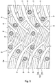
- FIG. 1 shows a tread portion 2 of a tire 1 according to the present embodiment.
- the tire 1 of the present embodiment has stud pin-fixing holes 5 provided in the tread portion 2, and stud pins (not shown) are mounted in the holes 5 when the tire 1 is used.
- the tire 1 of the present embodiment is suitably used, for example, as a winter tire for a passenger car.
- the stud pins provide great frictional force during running on ice.
- the structure of the tire 1 in a state where: the tire 1 is mounted to a normal rim and inflated to a normal internal pressure; no load is applied to the tire 1; and the stud pins are not mounted in the holes 5, will be described.
- the "normal rim” is a rim that is defined, in a standard system including a standard on which the tire is based, by the standard for each tire, and is, for example, the "standard rim” in the JATMA standard, the "Design Rim” in the TRA standard, or the “Measuring Rim” in the ETRTO standard.
- the "normal internal pressure” is an air pressure that is defined, in a standard system including a standard on which the tire is based, by the standard for each tire, and is the “maximum air pressure” in the JATMA standard, the maximum value indicated in the table "TIRE LOAD LIMITS AT VARIOUS COLD INFLATION PRESSURES" in the TRA standard, or the “INFLATION PRESSURE” in the ETRTO standard.
- the hardness of a rubber that forms the tread portion 2 is, for example, 45 to 65 degrees.
- the hardness of the rubber is indicated by a JIS-A hardness that conforms to JIS-K6253.
- the tread portion 2 includes, for example, a plurality of blocks demarcated by a plurality of grooves.
- the pattern of the tread portion 2 is not particularly limited in the present invention, and, for example, may be formed so as to include a rib that is continuous in the tire circumferential direction.
- the blocks provided to the tread portion 2 are provided with a plurality of recesses 7 that are recessed from a ground-contact surface 2s of the tread portion 2.
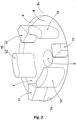
- FIG. 2 shows an enlarged perspective view of the recess 7 in FIG. 1 .
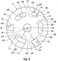
- FIG. 3 shows an enlarged plan view of the recess 7 in FIG. 1 .
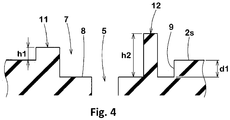
- FIG. 4 shows an end view taken along a line A-A in FIG. 3 .
- the recess 7 includes a bottom surface 8 and an inner circumferential surface 9 connected to the bottom surface 8.
- a region surrounded by an edge 7e having a closed contour is recessed.
- the contour of the recess 7 can be formed in any of various shapes such as a circular shape, an elliptical shape, an oval shape, and a polygonal shape.
- the recess 7 of the present embodiment has, for example, a circular contour.
- the width of the recess 7 (corresponding to the diameter of the recess 7 in the present embodiment) in a tread plan view is, for example, not greater than 20 mm, and preferably 14 to 18 mm. Accordingly, the ground-contact surface 2s of the tread portion 2 is ensured to have a sufficient area.
- the depth d1 of the recess 7 is, for example, 0.2 to 1.5 mm, and preferably 0.2 to 0.7 mm.
- the size of the recess 7 is not limited to such a size.
- the recess 7 is provided with a stud pin-fixing hole 5 that is open in the bottom surface 8, and a plurality of projections 10 that project from the bottom surface 8.
- the stud pin-fixing hole 5 has, for example, an inner diameter smaller than the outer diameter of the stud pin.
- the hole 5 has, for example, a circular contour in a plan view of the tread portion 2.
- the projections 10 include a first projection 11 that is connected to the ground-contact surface 2s and that projects outward in the tire radial direction of the ground-contact surface 2s.
- the first projection 11 prevents ice chips from entering the recess 7. Therefore, a reduction in the projecting height of the stud pin by ice chips can be inhibited.
- the first projection 11 is connected to the ground-contact surface 2s.
- the first projection 11 has excellent durability, and chipping or the like of the first projection 11 at the early stage is prevented, so that the first projection 11 improves on-ice performance over a long period of time.
- the length, in the circumferential direction of the inner circumferential surface 9, of the first projection 11 preferably gradually increases toward the hole 5.
- the outer surface of the first projection 11 is a trapezoidal shape.
- Such a first projection 11 easily falls in the circumferential direction of the inner circumferential surface 9 with a portion where the first projection 11 and the inner circumferential surface 9 are connected to each other acting as a fulcrum, and thus the first projection 11 allows ice chips to be effectively discharged.
- the trapezoidal shape of the outer surface includes not only a complete trapezoid but also a trapezoidal shape with rounded vertices and a trapezoidal shape with slightly curved sides.
- the maximum length L1, in the circumferential direction, of the first projection 11 is, for example, not greater than 5.0 mm, and preferably 1.0 to 3.0 mm.
- the length L1 is preferably 3% to 8% of the length, in the circumferential direction, of the inner circumferential surface 9.
- the minimum length L2, in the circumferential direction, of the first projection 11 is, for example, 0.50 to 0.70 times the length L1.
- Such a first projection 11 can exert the above-described effects while maintaining durability.
- the side surface of the first projection 11 includes, for example, a first surface 16 at the hole 5 side, and a second surface 17 and a third surface 18 between the first surface 16 and the inner circumferential surface 9.
- the first surface 16 is, for example, preferably recessed outward in a radial direction from the hole 5 toward the inner circumferential surface 9 (corresponding to the radial direction of the circular contour of the recess 7 in the present embodiment). Accordingly, the first surface 16 includes a portion that extends parallel to the inner circumferential surface 9 in a tread plan view.
- the distance L3 in the radial direction from the center of the hole 5 to the first surface 16 is, for example, not greater than 5.0 mm, and preferably 2.5 to 4.5 mm.
- the angle ⁇ 1 between the second surface 17 and the third surface 18 is, for example, preferably not greater than 90°, more preferably not greater than 45°, and 20 to 40° in the present embodiment.
- Such a first projection 11 easily appropriately deforms in the circumferential direction and effectively discharges ice chips within the recess 7.
- the height h1 of the first projection 11 from the ground-contact surface 2s is, for example, preferably 0.5 to 2.0 mm.
- Such a first projection 11 is less likely to be damaged when coming into contact with the ground, and effectively inhibits ice chips from entering the recess 7.
- the first projection 11 can enhance the stiffness of the rubber around the hole 5 and also serves to enhance the ability to hold the stud pin.
- the projections 10 of the present embodiment include a second projection 12 separated from the inner circumferential surface 9.
- the first length L4 along the circumferential direction, of the second projection 12 is larger than the second length L5, in the radial direction, of the second projection 12.
- the first length L4 is, for example, not greater than 5.0 mm, and preferably 2.5 to 4.5 mm.
- the second length L5 is, for example, 0.8 to 1.5 mm.
- the second projection 12 is flattened in the radial direction.
- Such a second projection 12 can fall in the radial direction when contact pressure is applied thereto, thereby effectively discharging ice chips from the recess 7.
- excellent discharge effect is exerted.
- the first length L4 of the second projection 12 is preferably larger than the length L1 of the first projection 11. Specifically, the first length L4 of the second projection 12 is preferably 1.5 to 2.5 times the length L1 of the first projection 11.
- the second length L5 is, for example, not greater than 0.5 times the first length L4, and preferably 0.25 to 0.40 times the first length L4. Such a second projection 12 easily falls in the radial direction and has excellent durability.
- the second projection 12 includes, for example, an inner surface 21 at the hole 5 side, and an outer surface 22 at the recess inner circumferential surface 9 side.
- Each of the inner surface 21 and the outer surface 22 extends along the inner circumferential surface 9 of the recess 7, and preferably extends parallel to the inner circumferential surface 9.
- two circular arc surfaces 23 are connected between the inner surface 21 and the outer surface 22. Accordingly, the second projection 12 is formed in an oval shape that is curved convexly outward in the radial direction in a tread plan view.
- the minimum distance L6 in the radial direction from the center of the hole 5 to the inner surface 21 is, for example, 3.0 to 4.0 mm.
- the inner surface 21 of the second projection 12 is preferably located inward in the radial direction of the first surface 16 of the first projection 11.
- the outer surface 22 of the second projection 12 is preferably located outward in the radial direction of the first surface 16 of the first projection 11.
- the second projection 12 preferably projects outward in the tire radial direction further than the first projection 11.
- the height h2 of the second projection 12 from the bottom surface 8 is, for example, preferably, 1.0 to 2.5 mm.
- a plurality of second projections 12 and a plurality of first projections 11 are provided around the hole 5 so as to be spaced apart from each other in the circumferential direction. Accordingly, the hole 5 is surrounded by the plurality of second projections 12 and the plurality of first projections 11. Two to four second projections 12 and two to four first projections 11 are preferably provided in the recess 7. The second projections 12 and the first projections 11 are preferably alternately provided in the circumferential direction along the inner circumferential surface 9.
- each of the lengths, in the circumferential direction, of the gaps between the first projections 11 and the second projections 12 is smaller than the length, in the circumferential direction, of each second projection 12.
- FIG. 5 shows an enlarged perspective view of a recess 7 of another embodiment of the present invention
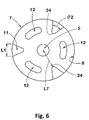
- FIG. 6 shows an enlarged plan view of FIG. 5
- elements that are common to the above-described embodiment are designated by the same reference characters, and the description thereof is omitted here.
- the length, in the circumferential direction along the inner circumferential surface 9, of each first projection 11 of this embodiment gradually decreases toward the hole 5. Accordingly, the outer surface of the first projection 11 is formed in a triangular shape in a tread plan view.
- Such a first projection 11 serves to exert the above-described effects and also to make it easier to identify the position of the hole 5, and further can enhance workability when inserting the stud pin into the hole 5.
- the triangular shape of the outer surface includes not only a complete triangle but also a triangular shape with rounded vertices and a triangular shape with slightly curved sides.
- the maximum length L1, in the circumferential direction, of the first projection 11 is, for example, not greater than 5.0 mm, and preferably 1.0 to 3.0 mm.
- the distance L7 from the center of the hole 5 to a vertex 24 of the first projection 11 is, for example, not greater than 5.0 mm, and preferably 2.5 to 4.5 mm.
- the angle ⁇ 2 between two surfaces, of the first projection 11, connected to each other via the vertex 24 is, for example, 40 to 60°.
- Such a first projection 11 effectively discharges ice chips.
- Tires with a size of 205/55R16 having the basic pattern in FIG. 1 and having the recesses shown in either FIG. 2 or FIG. 5 were produced as test tires on the basis of specifications in Table 1.
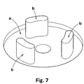
- a tire having the basic pattern in FIG. 1 and having recesses a as shown in FIG. 7 was produced as a test tire.
- each recess a of the tire of the comparative example is provided with only second projections b that are as described above.
- the tread pattern and the structures of the recesses and the second projections are common to the respective test tires.
- the respective test tires were tested for on-ice performance and stud pin dropping-off ratio.
- the common specifications and the test methods for the respective test tires are as follows. Mount rim: 16 ⁇ 6.5 Tire internal pressure: front wheel 240 kPa, rear wheel 240 kPa Test vehicle: a front-wheel-drive car having an engine displacement of 1400 cc Tire mounted position: all wheels
- the braking distance was measured when the test vehicle entered an icy road at 40 km/h and was suddenly braked with ABS operated. The test was conducted both on an icy road having a smooth surface on which the vehicle had not travelled (smooth icy road) and on an icy road having a surface to which ice chips and snow had adhered (rough icy road). The results of each test are indexes with the braking distance of the comparative example being regarded as 100. A lower value indicates that the braking distance is smaller and the on-ice performance is better.
- the stud pin dropping-off ratio was measured after the test vehicle travelled 30000 km in a cold city.
- the dropping-off ratio is the ratio of the number of stud pins dropped off by the travel to the total number of stud pins at the time of start of tire use.
- Example 1 Comparative example Example 1
- Example 2 Example 3
- Example 4 Example 5
- Example 6 Example 7
- Figure showing shapes of recess and projections FIG. 7 FIG. 2 FIG. 2 FIG. 2 FIG. 2 FIG. 2 FIG. 2 FIG. 2 FIG. 2 FIG. 2 FIG. 2 FIG. 2 FIG. 2 FIG.
Landscapes
- Engineering & Computer Science (AREA)
- Mechanical Engineering (AREA)
- Tires In General (AREA)
Abstract
Description
- The present invention relates to a tire and specifically relates to a tire having a stud pin-fixing hole provided in a tread portion.
- Japanese Laid-Open Patent Publication No.
2017-071339 - In the winter tire of Japanese Laid-Open Patent Publication No.
2017-071339 - The present invention has been made in view of the above-described problem, and a main object of the present invention is to provide a tire capable of exhibiting excellent on-ice performance.
- The present invention is directed to a tire including a tread portion, wherein: the tread portion includes a recess that is recessed from a ground-contact surface thereof; the recess includes a bottom surface and an inner circumferential surface that is connected to the bottom surface and the ground-contact surface; the recess is provided with a stud pin-fixing hole that is open in the bottom surface, and a plurality of projections that project from the bottom surface; and the projections include a first projection that is connected to the ground-contact surface and that projects outward in a tire radial direction of the ground-contact surface.
- Preferably, in a tread plan view of the tire according to the present invention, a length, in a circumferential direction along the inner circumferential surface, of the first projection gradually increases toward the hole.
- Preferably, in a tread plan view of the tire according to the present invention, a length, in a circumferential direction along the inner circumferential surface, of the first projection gradually decreases toward the hole.
- Preferably, in the tire according to the present invention, the projections include a second projection separated from the inner circumferential surface.
- Preferably, in the tire according to the present invention, the second projection projects outward in the tire radial direction further than the first projection.
- Preferably, in a tread plan view of the tire according to the present invention, a first length, in a circumferential direction along the inner circumferential surface, of the second projection is larger than a second length, in a radial direction from the hole toward the inner circumferential surface, of the second projection.
- Preferably, in the tire according to the present invention, the hole is surrounded by a plurality of the first projections and a plurality of the second projections.
- Preferably, in the tire according to the present invention, the first projections and the second projections are alternately provided in the circumferential direction along the inner circumferential surface.
- In the tire according to the present invention, the first projection prevents ice chips from entering the recess. Therefore, a reduction in a projecting height of a stud pin by ice chips can be inhibited. In addition, the first projection is connected to the ground-contact surface. Thus, the first projection has excellent durability, and chipping or the like of the first projection at the early stage is prevented, so that the first projection improves on-ice performance over a long period of time.
-
-
FIG. 1 is a development of a tread portion of a tire according to an embodiment; -
FIG. 2 is an enlarged perspective view of a recess inFIG. 1 ; -
FIG. 3 is an enlarged plan view of the recess inFIG. 1 ; -
FIG. 4 is an end view taken along a line A-A inFIG. 3 ; -
FIG. 5 is an enlarged perspective view of a recess of another embodiment of the present invention; -
FIG. 6 is an enlarged plan view of the recess inFIG. 5 ; and -
FIG. 7 is an enlarged perspective view of a recess of a comparative example. - Hereinafter, an embodiment of the present invention will be described with reference to the drawings.
FIG. 1 shows a tread portion 2 of a tire 1 according to the present embodiment. The tire 1 of the present embodiment has stud pin-fixing holes 5 provided in the tread portion 2, and stud pins (not shown) are mounted in theholes 5 when the tire 1 is used. The tire 1 of the present embodiment is suitably used, for example, as a winter tire for a passenger car. The stud pins provide great frictional force during running on ice. Hereinafter, regarding the structure of the tire 1, unless otherwise specified, the structure of the tire 1 in a state where: the tire 1 is mounted to a normal rim and inflated to a normal internal pressure; no load is applied to the tire 1; and the stud pins are not mounted in theholes 5, will be described. - The "normal rim" is a rim that is defined, in a standard system including a standard on which the tire is based, by the standard for each tire, and is, for example, the "standard rim" in the JATMA standard, the "Design Rim" in the TRA standard, or the "Measuring Rim" in the ETRTO standard.
- The "normal internal pressure" is an air pressure that is defined, in a standard system including a standard on which the tire is based, by the standard for each tire, and is the "maximum air pressure" in the JATMA standard, the maximum value indicated in the table "TIRE LOAD LIMITS AT VARIOUS COLD INFLATION PRESSURES" in the TRA standard, or the "INFLATION PRESSURE" in the ETRTO standard.
- The hardness of a rubber that forms the tread portion 2 is, for example, 45 to 65 degrees. In the present specification, the hardness of the rubber is indicated by a JIS-A hardness that conforms to JIS-K6253.
- The tread portion 2 includes, for example, a plurality of blocks demarcated by a plurality of grooves. The pattern of the tread portion 2 is not particularly limited in the present invention, and, for example, may be formed so as to include a rib that is continuous in the tire circumferential direction. The blocks provided to the tread portion 2 are provided with a plurality of
recesses 7 that are recessed from a ground-contact surface 2s of the tread portion 2. -
FIG. 2 shows an enlarged perspective view of therecess 7 inFIG. 1 .FIG. 3 shows an enlarged plan view of therecess 7 inFIG. 1 .FIG. 4 shows an end view taken along a line A-A inFIG. 3 . As shown inFIGS. 2 to 4 , therecess 7 includes abottom surface 8 and an innercircumferential surface 9 connected to thebottom surface 8. - As shown in
FIG. 2 , in therecess 7, for example, a region surrounded by anedge 7e having a closed contour is recessed. The contour of therecess 7 can be formed in any of various shapes such as a circular shape, an elliptical shape, an oval shape, and a polygonal shape. Therecess 7 of the present embodiment has, for example, a circular contour. - The width of the recess 7 (corresponding to the diameter of the
recess 7 in the present embodiment) in a tread plan view is, for example, not greater than 20 mm, and preferably 14 to 18 mm. Accordingly, the ground-contact surface 2s of the tread portion 2 is ensured to have a sufficient area. - As shown in
FIG. 4 , the depth d1 of therecess 7 is, for example, 0.2 to 1.5 mm, and preferably 0.2 to 0.7 mm. However, the size of therecess 7 is not limited to such a size. - As shown in
FIG. 2 , therecess 7 is provided with a stud pin-fixing hole 5 that is open in thebottom surface 8, and a plurality ofprojections 10 that project from thebottom surface 8. - The stud pin-
fixing hole 5 has, for example, an inner diameter smaller than the outer diameter of the stud pin. When the tire 1 is used, the stud pin is fitted into thehole 5, and a tip of the stud pin appears on the outer surface of the tread portion 2. Accordingly, great frictional force on ice is expected. Thehole 5 has, for example, a circular contour in a plan view of the tread portion 2. - The
projections 10 include afirst projection 11 that is connected to the ground-contact surface 2s and that projects outward in the tire radial direction of the ground-contact surface 2s. - The
first projection 11 prevents ice chips from entering therecess 7. Therefore, a reduction in the projecting height of the stud pin by ice chips can be inhibited. In addition, thefirst projection 11 is connected to the ground-contact surface 2s. Thus, thefirst projection 11 has excellent durability, and chipping or the like of thefirst projection 11 at the early stage is prevented, so that thefirst projection 11 improves on-ice performance over a long period of time. - As shown in
FIG. 3 , in a tread plan view, for example, the length, in the circumferential direction of the innercircumferential surface 9, of thefirst projection 11 preferably gradually increases toward thehole 5. Accordingly, in a tread plan view, the outer surface of thefirst projection 11 is a trapezoidal shape. Such afirst projection 11 easily falls in the circumferential direction of the innercircumferential surface 9 with a portion where thefirst projection 11 and the innercircumferential surface 9 are connected to each other acting as a fulcrum, and thus thefirst projection 11 allows ice chips to be effectively discharged. The trapezoidal shape of the outer surface includes not only a complete trapezoid but also a trapezoidal shape with rounded vertices and a trapezoidal shape with slightly curved sides. - The maximum length L1, in the circumferential direction, of the
first projection 11 is, for example, not greater than 5.0 mm, and preferably 1.0 to 3.0 mm. In addition, the length L1 is preferably 3% to 8% of the length, in the circumferential direction, of the innercircumferential surface 9. - The minimum length L2, in the circumferential direction, of the
first projection 11 is, for example, 0.50 to 0.70 times the length L1. Such afirst projection 11 can exert the above-described effects while maintaining durability. - The side surface of the
first projection 11 includes, for example, afirst surface 16 at thehole 5 side, and asecond surface 17 and athird surface 18 between thefirst surface 16 and the innercircumferential surface 9. - The
first surface 16 is, for example, preferably recessed outward in a radial direction from thehole 5 toward the inner circumferential surface 9 (corresponding to the radial direction of the circular contour of therecess 7 in the present embodiment). Accordingly, thefirst surface 16 includes a portion that extends parallel to the innercircumferential surface 9 in a tread plan view. The distance L3 in the radial direction from the center of thehole 5 to thefirst surface 16 is, for example, not greater than 5.0 mm, and preferably 2.5 to 4.5 mm. - The angle θ1 between the
second surface 17 and thethird surface 18 is, for example, preferably not greater than 90°, more preferably not greater than 45°, and 20 to 40° in the present embodiment. Such afirst projection 11 easily appropriately deforms in the circumferential direction and effectively discharges ice chips within therecess 7. - As shown in
FIG. 4 , the height h1 of thefirst projection 11 from the ground-contact surface 2s is, for example, preferably 0.5 to 2.0 mm. Such afirst projection 11 is less likely to be damaged when coming into contact with the ground, and effectively inhibits ice chips from entering therecess 7. In addition, thefirst projection 11 can enhance the stiffness of the rubber around thehole 5 and also serves to enhance the ability to hold the stud pin. - As shown in
FIG. 3 , for example, theprojections 10 of the present embodiment include asecond projection 12 separated from the innercircumferential surface 9. For example, the first length L4, along the circumferential direction, of thesecond projection 12 is larger than the second length L5, in the radial direction, of thesecond projection 12. The first length L4 is, for example, not greater than 5.0 mm, and preferably 2.5 to 4.5 mm. The second length L5 is, for example, 0.8 to 1.5 mm. Accordingly, thesecond projection 12 is flattened in the radial direction. Such asecond projection 12 can fall in the radial direction when contact pressure is applied thereto, thereby effectively discharging ice chips from therecess 7. In particular, in the present embodiment, since thefirst projection 11 easily falls in the circumferential direction, and thesecond projection 12 easily falls in the radial direction, excellent discharge effect is exerted. - The first length L4 of the
second projection 12 is preferably larger than the length L1 of thefirst projection 11. Specifically, the first length L4 of thesecond projection 12 is preferably 1.5 to 2.5 times the length L1 of thefirst projection 11. - The second length L5 is, for example, not greater than 0.5 times the first length L4, and preferably 0.25 to 0.40 times the first length L4. Such a
second projection 12 easily falls in the radial direction and has excellent durability. - The
second projection 12 includes, for example, aninner surface 21 at thehole 5 side, and anouter surface 22 at the recess innercircumferential surface 9 side. Each of theinner surface 21 and theouter surface 22 extends along the innercircumferential surface 9 of therecess 7, and preferably extends parallel to the innercircumferential surface 9. In addition, two circular arc surfaces 23 are connected between theinner surface 21 and theouter surface 22. Accordingly, thesecond projection 12 is formed in an oval shape that is curved convexly outward in the radial direction in a tread plan view. - The minimum distance L6 in the radial direction from the center of the
hole 5 to theinner surface 21 is, for example, 3.0 to 4.0 mm. For example, theinner surface 21 of thesecond projection 12 is preferably located inward in the radial direction of thefirst surface 16 of thefirst projection 11. In addition, theouter surface 22 of thesecond projection 12 is preferably located outward in the radial direction of thefirst surface 16 of thefirst projection 11. Such asecond projection 12 can effectively inhibit ice chips from remaining in therecess 7. - As shown in
FIG. 4 , thesecond projection 12 preferably projects outward in the tire radial direction further than thefirst projection 11. The height h2 of thesecond projection 12 from thebottom surface 8 is, for example, preferably, 1.0 to 2.5 mm. - As shown in
FIG. 3 , a plurality ofsecond projections 12 and a plurality offirst projections 11 are provided around thehole 5 so as to be spaced apart from each other in the circumferential direction. Accordingly, thehole 5 is surrounded by the plurality ofsecond projections 12 and the plurality offirst projections 11. Two to foursecond projections 12 and two to fourfirst projections 11 are preferably provided in therecess 7. Thesecond projections 12 and thefirst projections 11 are preferably alternately provided in the circumferential direction along the innercircumferential surface 9. - The sizes of the gaps between the
first projections 11 and thesecond projections 12 are not particularly limited. As a preferable mode, in the present embodiment, each of the lengths, in the circumferential direction, of the gaps between thefirst projections 11 and thesecond projections 12 is smaller than the length, in the circumferential direction, of eachsecond projection 12. -
FIG. 5 shows an enlarged perspective view of arecess 7 of another embodiment of the present invention, andFIG. 6 shows an enlarged plan view ofFIG. 5 . InFIGS. 5 and6 , elements that are common to the above-described embodiment are designated by the same reference characters, and the description thereof is omitted here. As shown inFIGS. 5 and6 , in a tread plan view, the length, in the circumferential direction along the innercircumferential surface 9, of eachfirst projection 11 of this embodiment gradually decreases toward thehole 5. Accordingly, the outer surface of thefirst projection 11 is formed in a triangular shape in a tread plan view. Such afirst projection 11 serves to exert the above-described effects and also to make it easier to identify the position of thehole 5, and further can enhance workability when inserting the stud pin into thehole 5. The triangular shape of the outer surface includes not only a complete triangle but also a triangular shape with rounded vertices and a triangular shape with slightly curved sides. - As shown in
FIG. 6 , the maximum length L1, in the circumferential direction, of thefirst projection 11 is, for example, not greater than 5.0 mm, and preferably 1.0 to 3.0 mm. The distance L7 from the center of thehole 5 to avertex 24 of thefirst projection 11 is, for example, not greater than 5.0 mm, and preferably 2.5 to 4.5 mm. - As shown in
FIG. 6 , the angle θ2 between two surfaces, of thefirst projection 11, connected to each other via thevertex 24 is, for example, 40 to 60°. Such afirst projection 11 effectively discharges ice chips. - Although the tire according to the embodiment of the present invention has been described in detail above, the present invention is not limited to the above specific embodiment, and various modifications can be made to implement the present invention.
- Tires with a size of 205/55R16 having the basic pattern in
FIG. 1 and having the recesses shown in eitherFIG. 2 orFIG. 5 were produced as test tires on the basis of specifications in Table 1. As a comparative example, a tire having the basic pattern inFIG. 1 and having recesses a as shown inFIG. 7 was produced as a test tire. As shown inFIG. 7 , each recess a of the tire of the comparative example is provided with only second projections b that are as described above. The tread pattern and the structures of the recesses and the second projections are common to the respective test tires. The respective test tires were tested for on-ice performance and stud pin dropping-off ratio. The common specifications and the test methods for the respective test tires are as follows.
Mount rim: 16×6.5
Tire internal pressure: front wheel 240 kPa, rear wheel 240 kPa
Test vehicle: a front-wheel-drive car having an engine displacement of 1400 cc
Tire mounted position: all wheels - The braking distance was measured when the test vehicle entered an icy road at 40 km/h and was suddenly braked with ABS operated. The test was conducted both on an icy road having a smooth surface on which the vehicle had not travelled (smooth icy road) and on an icy road having a surface to which ice chips and snow had adhered (rough icy road). The results of each test are indexes with the braking distance of the comparative example being regarded as 100. A lower value indicates that the braking distance is smaller and the on-ice performance is better.
- The stud pin dropping-off ratio was measured after the test vehicle travelled 30000 km in a cold city. The dropping-off ratio is the ratio of the number of stud pins dropped off by the travel to the total number of stud pins at the time of start of tire use.
- The test results are shown in Table 1.
[Table 1] Comparative example Example 1 Example 2 Example 3 Example 4 Example 5 Example 6 Example 7 Example 8 Figure showing shapes of recess and projections FIG. 7 FIG. 2 FIG. 2 FIG. 2 FIG. 2 FIG. 2 FIG. 2 FIG. 2 FIG. 5 Distance L3 from hole to first surface of first projection (mm) - 3.5 2.5 4.5 3.5 3.5 3.5 3.5 3.5 LengthLl of first projection (mm) - 2.5 2.5 2.5 1.5 3.5 2.5 2.5 2.5 Height h1 of first projection (mm) - 0.5 0.5 0.5 0.5 0.5 0.3 1.0 0.5 On-ice performance on smooth icy road (index) 100 97 98 97 97 97 98 97 97 On-ice performance on rough icy road (index) 100 95 96 95 96 96 96 95 95 Stud pin dropping-off ratio (%) 3.5 2.0 2.0 2.5 2.0 2.0 2.5 2.0 2.0 - As shown in Table 1, it was confirmed that the tire of each Example exhibits excellent on-ice performance. In addition, it was also confirmed that the tire of each Example has a low stud pin dropping-off ratio.
Claims (8)
- A tire (1) comprising a tread portion (2), wherein
the tread portion (2) includes a recess (7) that is recessed from a ground-contact surface (2s) thereof,
the recess (7) includes a bottom surface (8) and an inner circumferential surface (9) that is connected to the bottom surface (8) and the ground-contact surface (2s),
the recess (7) is provided with a stud pin-fixing hole (5) that is open in the bottom surface (8), and a plurality of projections (10) that project from the bottom surface (8), and
the projections (10) include a first projection (11) that is connected to the ground-contact surface (2s) and that projects outward in a tire radial direction of the ground-contact surface (2s). - The tire (1) according to claim 1, wherein, in a tread plan view, a length, in a circumferential direction along the inner circumferential surface (9), of the first projection (11) gradually increases toward the hole (5).
- The tire (1) according to claim 1, wherein, in a tread plan view, a length, in a circumferential direction along the inner circumferential surface (9), of the first projection (11) gradually decreases toward the hole (5).
- The tire (1) according to any one of claims 1 to 3, wherein the projections (10) include a second projection (12) separated from the inner circumferential surface (9).
- The tire (1) according to claim 4, wherein the second projection (12) projects outward in the tire radial direction further than the first projection (11).
- The tire (1) according to claim 4 or 5, wherein, in a tread plan view, a first length (L4), in a circumferential direction along the inner circumferential surface (9), of the second projection (12) is larger than a second length (L5), in a radial direction from the hole (5) toward the inner circumferential surface (9), of the second projection (12).
- The tire (1) according to any one of claims 4 to 6, wherein the hole (5) is surrounded by a plurality of the first projections (11) and a plurality of the second projections (12).
- The tire (1) according to claim 7, wherein the first projections (11) and the second projections (12) are alternately provided in the circumferential direction along the inner circumferential surface (9).
Applications Claiming Priority (1)
| Application Number | Priority Date | Filing Date | Title |
|---|---|---|---|
| JP2019027584A JP7200734B2 (en) | 2019-02-19 | 2019-02-19 | tire |
Publications (2)
| Publication Number | Publication Date |
|---|---|
| EP3698985A1 true EP3698985A1 (en) | 2020-08-26 |
| EP3698985B1 EP3698985B1 (en) | 2021-09-01 |
Family
ID=69571833
Family Applications (1)
| Application Number | Title | Priority Date | Filing Date |
|---|---|---|---|
| EP20156644.5A Active EP3698985B1 (en) | 2019-02-19 | 2020-02-11 | Tire |
Country Status (3)
| Country | Link |
|---|---|
| EP (1) | EP3698985B1 (en) |
| JP (1) | JP7200734B2 (en) |
| CN (1) | CN111572287B (en) |
Citations (5)
| Publication number | Priority date | Publication date | Assignee | Title |
|---|---|---|---|---|
| JPS6294402A (en) * | 1985-10-18 | 1987-04-30 | Bridgestone Corp | Spike tire |
| WO2009147047A1 (en) * | 2008-06-03 | 2009-12-10 | Societe De Technologie Michelin | Tyre for driving on ice |
| DE102009044547A1 (en) * | 2009-11-16 | 2011-05-19 | Continental Reifen Deutschland Gmbh | Tread pattern of a pneumatic vehicle tire |
| EP3031628A1 (en) * | 2014-12-05 | 2016-06-15 | Continental Reifen Deutschland GmbH | Pneumatic tyres for a vehicle |
| EP3153335A1 (en) * | 2015-10-08 | 2017-04-12 | Sumitomo Rubber Industries, Ltd. | Winter tire |
Family Cites Families (6)
| Publication number | Priority date | Publication date | Assignee | Title |
|---|---|---|---|---|
| JP5009050B2 (en) * | 2007-05-23 | 2012-08-22 | 東洋ゴム工業株式会社 | Pneumatic tire |
| JP4488099B2 (en) * | 2008-09-18 | 2010-06-23 | 横浜ゴム株式会社 | Pneumatic tire |
| US8376007B2 (en) * | 2010-03-30 | 2013-02-19 | The Goodyear Tire & Rubber Company | Structure for tread pattern having void ring, pedestal and cylindrical voids |
| JP5950625B2 (en) * | 2012-02-29 | 2016-07-13 | 株式会社ブリヂストン | tire |
| JP5860451B2 (en) * | 2013-12-27 | 2016-02-16 | 住友ゴム工業株式会社 | Winter tires |
| JP6360459B2 (en) * | 2015-05-26 | 2018-07-18 | 住友ゴム工業株式会社 | Winter tires |
-
2019
- 2019-02-19 JP JP2019027584A patent/JP7200734B2/en active Active
-
2020
- 2020-01-17 CN CN202010050142.4A patent/CN111572287B/en active Active
- 2020-02-11 EP EP20156644.5A patent/EP3698985B1/en active Active
Patent Citations (6)
| Publication number | Priority date | Publication date | Assignee | Title |
|---|---|---|---|---|
| JPS6294402A (en) * | 1985-10-18 | 1987-04-30 | Bridgestone Corp | Spike tire |
| WO2009147047A1 (en) * | 2008-06-03 | 2009-12-10 | Societe De Technologie Michelin | Tyre for driving on ice |
| DE102009044547A1 (en) * | 2009-11-16 | 2011-05-19 | Continental Reifen Deutschland Gmbh | Tread pattern of a pneumatic vehicle tire |
| EP3031628A1 (en) * | 2014-12-05 | 2016-06-15 | Continental Reifen Deutschland GmbH | Pneumatic tyres for a vehicle |
| EP3153335A1 (en) * | 2015-10-08 | 2017-04-12 | Sumitomo Rubber Industries, Ltd. | Winter tire |
| JP2017071339A (en) | 2015-10-08 | 2017-04-13 | 住友ゴム工業株式会社 | Winter tire |
Also Published As
| Publication number | Publication date |
|---|---|
| JP2020131907A (en) | 2020-08-31 |
| JP7200734B2 (en) | 2023-01-10 |
| EP3698985B1 (en) | 2021-09-01 |
| RU2020107001A (en) | 2021-08-16 |
| CN111572287A (en) | 2020-08-25 |
| CN111572287B (en) | 2023-06-20 |
Similar Documents
| Publication | Publication Date | Title |
|---|---|---|
| EP3098089B1 (en) | Winter tire | |
| EP3025874B1 (en) | Pneumatic tire | |
| US8474498B2 (en) | Pneumatic tire | |
| US8640750B2 (en) | Pneumatic tire with tread having shoulder blocks and crown blocks | |
| US9090134B2 (en) | Pneumatic tire | |
| US9102203B2 (en) | Pneumatic tire | |
| US8925602B2 (en) | Pneumatic tire | |
| US10232672B2 (en) | Winter tire | |
| EP3081400B1 (en) | Tire for winter | |
| JP4996670B2 (en) | Pneumatic tire | |
| US9004125B2 (en) | Pneumatic tire | |
| JP7508878B2 (en) | tire | |
| US20200198408A1 (en) | Tire | |
| EP3988336B1 (en) | Tire | |
| JPWO2019138792A1 (en) | Studd tires and pneumatic tires | |
| EP3698985B1 (en) | Tire | |
| JP7625835B2 (en) | tire | |
| JP2025004602A (en) | tire | |
| EP3925797A1 (en) | Tire | |
| JP7643039B2 (en) | tire | |
| JP7683213B2 (en) | tire | |
| RU2800025C2 (en) | Tire | |
| JP2022162822A (en) | tire |
Legal Events
| Date | Code | Title | Description |
|---|---|---|---|
| PUAI | Public reference made under article 153(3) epc to a published international application that has entered the european phase |
Free format text: ORIGINAL CODE: 0009012 |
|
| STAA | Information on the status of an ep patent application or granted ep patent |
Free format text: STATUS: THE APPLICATION HAS BEEN PUBLISHED |
|
| AK | Designated contracting states |
Kind code of ref document: A1 Designated state(s): AL AT BE BG CH CY CZ DE DK EE ES FI FR GB GR HR HU IE IS IT LI LT LU LV MC MK MT NL NO PL PT RO RS SE SI SK SM TR |
|
| AX | Request for extension of the european patent |
Extension state: BA ME |
|
| STAA | Information on the status of an ep patent application or granted ep patent |
Free format text: STATUS: REQUEST FOR EXAMINATION WAS MADE |
|
| 17P | Request for examination filed |
Effective date: 20201223 |
|
| RBV | Designated contracting states (corrected) |
Designated state(s): AL AT BE BG CH CY CZ DE DK EE ES FI FR GB GR HR HU IE IS IT LI LT LU LV MC MK MT NL NO PL PT RO RS SE SI SK SM TR |
|
| RIC1 | Information provided on ipc code assigned before grant |
Ipc: B60C 11/16 20060101ALI20210305BHEP Ipc: B60C 11/03 20060101AFI20210305BHEP |
|
| GRAP | Despatch of communication of intention to grant a patent |
Free format text: ORIGINAL CODE: EPIDOSNIGR1 |
|
| STAA | Information on the status of an ep patent application or granted ep patent |
Free format text: STATUS: GRANT OF PATENT IS INTENDED |
|
| INTG | Intention to grant announced |
Effective date: 20210420 |
|
| GRAS | Grant fee paid |
Free format text: ORIGINAL CODE: EPIDOSNIGR3 |
|
| GRAA | (expected) grant |
Free format text: ORIGINAL CODE: 0009210 |
|
| STAA | Information on the status of an ep patent application or granted ep patent |
Free format text: STATUS: THE PATENT HAS BEEN GRANTED |
|
| AK | Designated contracting states |
Kind code of ref document: B1 Designated state(s): AL AT BE BG CH CY CZ DE DK EE ES FI FR GB GR HR HU IE IS IT LI LT LU LV MC MK MT NL NO PL PT RO RS SE SI SK SM TR |
|
| REG | Reference to a national code |
Ref country code: GB Ref legal event code: FG4D |
|
| REG | Reference to a national code |
Ref country code: CH Ref legal event code: EP Ref country code: AT Ref legal event code: REF Ref document number: 1425843 Country of ref document: AT Kind code of ref document: T Effective date: 20210915 |
|
| REG | Reference to a national code |
Ref country code: DE Ref legal event code: R096 Ref document number: 602020000460 Country of ref document: DE |
|
| REG | Reference to a national code |
Ref country code: IE Ref legal event code: FG4D |
|
| REG | Reference to a national code |
Ref country code: FI Ref legal event code: FGE |
|
| REG | Reference to a national code |
Ref country code: LT Ref legal event code: MG9D |
|
| REG | Reference to a national code |
Ref country code: NL Ref legal event code: MP Effective date: 20210901 |
|
| PG25 | Lapsed in a contracting state [announced via postgrant information from national office to epo] |
Ref country code: BG Free format text: LAPSE BECAUSE OF FAILURE TO SUBMIT A TRANSLATION OF THE DESCRIPTION OR TO PAY THE FEE WITHIN THE PRESCRIBED TIME-LIMIT Effective date: 20211201 Ref country code: LT Free format text: LAPSE BECAUSE OF FAILURE TO SUBMIT A TRANSLATION OF THE DESCRIPTION OR TO PAY THE FEE WITHIN THE PRESCRIBED TIME-LIMIT Effective date: 20210901 Ref country code: NO Free format text: LAPSE BECAUSE OF FAILURE TO SUBMIT A TRANSLATION OF THE DESCRIPTION OR TO PAY THE FEE WITHIN THE PRESCRIBED TIME-LIMIT Effective date: 20211201 Ref country code: HR Free format text: LAPSE BECAUSE OF FAILURE TO SUBMIT A TRANSLATION OF THE DESCRIPTION OR TO PAY THE FEE WITHIN THE PRESCRIBED TIME-LIMIT Effective date: 20210901 Ref country code: ES Free format text: LAPSE BECAUSE OF FAILURE TO SUBMIT A TRANSLATION OF THE DESCRIPTION OR TO PAY THE FEE WITHIN THE PRESCRIBED TIME-LIMIT Effective date: 20210901 Ref country code: RS Free format text: LAPSE BECAUSE OF FAILURE TO SUBMIT A TRANSLATION OF THE DESCRIPTION OR TO PAY THE FEE WITHIN THE PRESCRIBED TIME-LIMIT Effective date: 20210901 Ref country code: SE Free format text: LAPSE BECAUSE OF FAILURE TO SUBMIT A TRANSLATION OF THE DESCRIPTION OR TO PAY THE FEE WITHIN THE PRESCRIBED TIME-LIMIT Effective date: 20210901 |
|
| REG | Reference to a national code |
Ref country code: AT Ref legal event code: MK05 Ref document number: 1425843 Country of ref document: AT Kind code of ref document: T Effective date: 20210901 |
|
| PG25 | Lapsed in a contracting state [announced via postgrant information from national office to epo] |
Ref country code: PL Free format text: LAPSE BECAUSE OF FAILURE TO SUBMIT A TRANSLATION OF THE DESCRIPTION OR TO PAY THE FEE WITHIN THE PRESCRIBED TIME-LIMIT Effective date: 20210901 Ref country code: LV Free format text: LAPSE BECAUSE OF FAILURE TO SUBMIT A TRANSLATION OF THE DESCRIPTION OR TO PAY THE FEE WITHIN THE PRESCRIBED TIME-LIMIT Effective date: 20210901 Ref country code: GR Free format text: LAPSE BECAUSE OF FAILURE TO SUBMIT A TRANSLATION OF THE DESCRIPTION OR TO PAY THE FEE WITHIN THE PRESCRIBED TIME-LIMIT Effective date: 20211202 |
|
| PG25 | Lapsed in a contracting state [announced via postgrant information from national office to epo] |
Ref country code: AT Free format text: LAPSE BECAUSE OF FAILURE TO SUBMIT A TRANSLATION OF THE DESCRIPTION OR TO PAY THE FEE WITHIN THE PRESCRIBED TIME-LIMIT Effective date: 20210901 |
|
| PG25 | Lapsed in a contracting state [announced via postgrant information from national office to epo] |
Ref country code: IS Free format text: LAPSE BECAUSE OF FAILURE TO SUBMIT A TRANSLATION OF THE DESCRIPTION OR TO PAY THE FEE WITHIN THE PRESCRIBED TIME-LIMIT Effective date: 20220101 Ref country code: SM Free format text: LAPSE BECAUSE OF FAILURE TO SUBMIT A TRANSLATION OF THE DESCRIPTION OR TO PAY THE FEE WITHIN THE PRESCRIBED TIME-LIMIT Effective date: 20210901 Ref country code: SK Free format text: LAPSE BECAUSE OF FAILURE TO SUBMIT A TRANSLATION OF THE DESCRIPTION OR TO PAY THE FEE WITHIN THE PRESCRIBED TIME-LIMIT Effective date: 20210901 Ref country code: RO Free format text: LAPSE BECAUSE OF FAILURE TO SUBMIT A TRANSLATION OF THE DESCRIPTION OR TO PAY THE FEE WITHIN THE PRESCRIBED TIME-LIMIT Effective date: 20210901 Ref country code: PT Free format text: LAPSE BECAUSE OF FAILURE TO SUBMIT A TRANSLATION OF THE DESCRIPTION OR TO PAY THE FEE WITHIN THE PRESCRIBED TIME-LIMIT Effective date: 20220103 Ref country code: NL Free format text: LAPSE BECAUSE OF FAILURE TO SUBMIT A TRANSLATION OF THE DESCRIPTION OR TO PAY THE FEE WITHIN THE PRESCRIBED TIME-LIMIT Effective date: 20210901 Ref country code: EE Free format text: LAPSE BECAUSE OF FAILURE TO SUBMIT A TRANSLATION OF THE DESCRIPTION OR TO PAY THE FEE WITHIN THE PRESCRIBED TIME-LIMIT Effective date: 20210901 Ref country code: CZ Free format text: LAPSE BECAUSE OF FAILURE TO SUBMIT A TRANSLATION OF THE DESCRIPTION OR TO PAY THE FEE WITHIN THE PRESCRIBED TIME-LIMIT Effective date: 20210901 Ref country code: AL Free format text: LAPSE BECAUSE OF FAILURE TO SUBMIT A TRANSLATION OF THE DESCRIPTION OR TO PAY THE FEE WITHIN THE PRESCRIBED TIME-LIMIT Effective date: 20210901 |
|
| REG | Reference to a national code |
Ref country code: DE Ref legal event code: R097 Ref document number: 602020000460 Country of ref document: DE |
|
| PLBE | No opposition filed within time limit |
Free format text: ORIGINAL CODE: 0009261 |
|
| STAA | Information on the status of an ep patent application or granted ep patent |
Free format text: STATUS: NO OPPOSITION FILED WITHIN TIME LIMIT |
|
| PG25 | Lapsed in a contracting state [announced via postgrant information from national office to epo] |
Ref country code: IT Free format text: LAPSE BECAUSE OF FAILURE TO SUBMIT A TRANSLATION OF THE DESCRIPTION OR TO PAY THE FEE WITHIN THE PRESCRIBED TIME-LIMIT Effective date: 20210901 Ref country code: DK Free format text: LAPSE BECAUSE OF FAILURE TO SUBMIT A TRANSLATION OF THE DESCRIPTION OR TO PAY THE FEE WITHIN THE PRESCRIBED TIME-LIMIT Effective date: 20210901 |
|
| 26N | No opposition filed |
Effective date: 20220602 |
|
| PG25 | Lapsed in a contracting state [announced via postgrant information from national office to epo] |
Ref country code: SI Free format text: LAPSE BECAUSE OF FAILURE TO SUBMIT A TRANSLATION OF THE DESCRIPTION OR TO PAY THE FEE WITHIN THE PRESCRIBED TIME-LIMIT Effective date: 20210901 |
|
| PG25 | Lapsed in a contracting state [announced via postgrant information from national office to epo] |
Ref country code: MC Free format text: LAPSE BECAUSE OF FAILURE TO SUBMIT A TRANSLATION OF THE DESCRIPTION OR TO PAY THE FEE WITHIN THE PRESCRIBED TIME-LIMIT Effective date: 20210901 |
|
| REG | Reference to a national code |
Ref country code: BE Ref legal event code: MM Effective date: 20220228 |
|
| PG25 | Lapsed in a contracting state [announced via postgrant information from national office to epo] |
Ref country code: LU Free format text: LAPSE BECAUSE OF NON-PAYMENT OF DUE FEES Effective date: 20220211 |
|
| PG25 | Lapsed in a contracting state [announced via postgrant information from national office to epo] |
Ref country code: IE Free format text: LAPSE BECAUSE OF NON-PAYMENT OF DUE FEES Effective date: 20220211 |
|
| PG25 | Lapsed in a contracting state [announced via postgrant information from national office to epo] |
Ref country code: BE Free format text: LAPSE BECAUSE OF NON-PAYMENT OF DUE FEES Effective date: 20220228 |
|
| P01 | Opt-out of the competence of the unified patent court (upc) registered |
Effective date: 20230510 |
|
| REG | Reference to a national code |
Ref country code: CH Ref legal event code: PL |
|
| PG25 | Lapsed in a contracting state [announced via postgrant information from national office to epo] |
Ref country code: LI Free format text: LAPSE BECAUSE OF NON-PAYMENT OF DUE FEES Effective date: 20230228 Ref country code: CH Free format text: LAPSE BECAUSE OF NON-PAYMENT OF DUE FEES Effective date: 20230228 |
|
| PG25 | Lapsed in a contracting state [announced via postgrant information from national office to epo] |
Ref country code: MK Free format text: LAPSE BECAUSE OF FAILURE TO SUBMIT A TRANSLATION OF THE DESCRIPTION OR TO PAY THE FEE WITHIN THE PRESCRIBED TIME-LIMIT Effective date: 20210901 Ref country code: CY Free format text: LAPSE BECAUSE OF FAILURE TO SUBMIT A TRANSLATION OF THE DESCRIPTION OR TO PAY THE FEE WITHIN THE PRESCRIBED TIME-LIMIT Effective date: 20210901 |
|
| PG25 | Lapsed in a contracting state [announced via postgrant information from national office to epo] |
Ref country code: HU Free format text: LAPSE BECAUSE OF FAILURE TO SUBMIT A TRANSLATION OF THE DESCRIPTION OR TO PAY THE FEE WITHIN THE PRESCRIBED TIME-LIMIT; INVALID AB INITIO Effective date: 20200211 |
|
| PG25 | Lapsed in a contracting state [announced via postgrant information from national office to epo] |
Ref country code: MT Free format text: LAPSE BECAUSE OF FAILURE TO SUBMIT A TRANSLATION OF THE DESCRIPTION OR TO PAY THE FEE WITHIN THE PRESCRIBED TIME-LIMIT Effective date: 20210901 |
|
| GBPC | Gb: european patent ceased through non-payment of renewal fee |
Effective date: 20240211 |
|
| PG25 | Lapsed in a contracting state [announced via postgrant information from national office to epo] |
Ref country code: GB Free format text: LAPSE BECAUSE OF NON-PAYMENT OF DUE FEES Effective date: 20240211 |
|
| PG25 | Lapsed in a contracting state [announced via postgrant information from national office to epo] |
Ref country code: GB Free format text: LAPSE BECAUSE OF NON-PAYMENT OF DUE FEES Effective date: 20240211 |
|
| PG25 | Lapsed in a contracting state [announced via postgrant information from national office to epo] |
Ref country code: TR Free format text: LAPSE BECAUSE OF FAILURE TO SUBMIT A TRANSLATION OF THE DESCRIPTION OR TO PAY THE FEE WITHIN THE PRESCRIBED TIME-LIMIT Effective date: 20210901 |
|
| PGFP | Annual fee paid to national office [announced via postgrant information from national office to epo] |
Ref country code: FR Payment date: 20251231 Year of fee payment: 7 |
|
| PGFP | Annual fee paid to national office [announced via postgrant information from national office to epo] |
Ref country code: DE Payment date: 20251230 Year of fee payment: 7 |
|
| PGFP | Annual fee paid to national office [announced via postgrant information from national office to epo] |
Ref country code: FI Payment date: 20260213 Year of fee payment: 7 |