EP3698914B1 - Pressurization jig for pressurizing bus bar and battery module manufacturing system comprising same - Google Patents
Pressurization jig for pressurizing bus bar and battery module manufacturing system comprising same Download PDFInfo
- Publication number
- EP3698914B1 EP3698914B1 EP19781991.5A EP19781991A EP3698914B1 EP 3698914 B1 EP3698914 B1 EP 3698914B1 EP 19781991 A EP19781991 A EP 19781991A EP 3698914 B1 EP3698914 B1 EP 3698914B1
- Authority
- EP
- European Patent Office
- Prior art keywords
- bus bar
- frame
- distance adjusting
- adjusting unit
- pressing
- Prior art date
- Legal status (The legal status is an assumption and is not a legal conclusion. Google has not performed a legal analysis and makes no representation as to the accuracy of the status listed.)
- Active
Links
Images



Classifications
-
- B—PERFORMING OPERATIONS; TRANSPORTING
- B23—MACHINE TOOLS; METAL-WORKING NOT OTHERWISE PROVIDED FOR
- B23K—SOLDERING OR UNSOLDERING; WELDING; CLADDING OR PLATING BY SOLDERING OR WELDING; CUTTING BY APPLYING HEAT LOCALLY, e.g. FLAME CUTTING; WORKING BY LASER BEAM
- B23K31/00—Processes relevant to this subclass, specially adapted for particular articles or purposes, but not covered by any single one of main groups B23K1/00 - B23K28/00
- B23K31/02—Processes relevant to this subclass, specially adapted for particular articles or purposes, but not covered by any single one of main groups B23K1/00 - B23K28/00 relating to soldering or welding
-
- B—PERFORMING OPERATIONS; TRANSPORTING
- B23—MACHINE TOOLS; METAL-WORKING NOT OTHERWISE PROVIDED FOR
- B23K—SOLDERING OR UNSOLDERING; WELDING; CLADDING OR PLATING BY SOLDERING OR WELDING; CUTTING BY APPLYING HEAT LOCALLY, e.g. FLAME CUTTING; WORKING BY LASER BEAM
- B23K37/00—Auxiliary devices or processes, not specially adapted for a procedure covered by only one of the other main groups of this subclass
- B23K37/04—Auxiliary devices or processes, not specially adapted for a procedure covered by only one of the other main groups of this subclass for holding or positioning work
- B23K37/0426—Fixtures for other work
- B23K37/0435—Clamps
- B23K37/0443—Jigs
-
- B—PERFORMING OPERATIONS; TRANSPORTING
- B25—HAND TOOLS; PORTABLE POWER-DRIVEN TOOLS; MANIPULATORS
- B25B—TOOLS OR BENCH DEVICES NOT OTHERWISE PROVIDED FOR, FOR FASTENING, CONNECTING, DISENGAGING, OR HOLDING
- B25B5/00—Clamps
- B25B5/06—Arrangements for positively actuating jaws
- B25B5/061—Arrangements for positively actuating jaws with fluid drive
- B25B5/062—Arrangements for positively actuating jaws with fluid drive with clamping means pivoting around an axis parallel to the pressing direction
-
- H—ELECTRICITY
- H01—ELECTRIC ELEMENTS
- H01M—PROCESSES OR MEANS, e.g. BATTERIES, FOR THE DIRECT CONVERSION OF CHEMICAL ENERGY INTO ELECTRICAL ENERGY
- H01M10/00—Secondary cells; Manufacture thereof
- H01M10/04—Construction or manufacture in general
- H01M10/0404—Machines for assembling batteries
-
- H—ELECTRICITY
- H01—ELECTRIC ELEMENTS
- H01M—PROCESSES OR MEANS, e.g. BATTERIES, FOR THE DIRECT CONVERSION OF CHEMICAL ENERGY INTO ELECTRICAL ENERGY
- H01M10/00—Secondary cells; Manufacture thereof
- H01M10/04—Construction or manufacture in general
- H01M10/0413—Large-sized flat cells or batteries for motive or stationary systems with plate-like electrodes
-
- H—ELECTRICITY
- H01—ELECTRIC ELEMENTS
- H01M—PROCESSES OR MEANS, e.g. BATTERIES, FOR THE DIRECT CONVERSION OF CHEMICAL ENERGY INTO ELECTRICAL ENERGY
- H01M10/00—Secondary cells; Manufacture thereof
- H01M10/04—Construction or manufacture in general
- H01M10/0481—Compression means other than compression means for stacks of electrodes and separators
-
- H—ELECTRICITY
- H01—ELECTRIC ELEMENTS
- H01M—PROCESSES OR MEANS, e.g. BATTERIES, FOR THE DIRECT CONVERSION OF CHEMICAL ENERGY INTO ELECTRICAL ENERGY
- H01M50/00—Constructional details or processes of manufacture of the non-active parts of electrochemical cells other than fuel cells, e.g. hybrid cells
- H01M50/20—Mountings; Secondary casings or frames; Racks, modules or packs; Suspension devices; Shock absorbers; Transport or carrying devices; Holders
- H01M50/204—Racks, modules or packs for multiple batteries or multiple cells
- H01M50/207—Racks, modules or packs for multiple batteries or multiple cells characterised by their shape
- H01M50/211—Racks, modules or packs for multiple batteries or multiple cells characterised by their shape adapted for pouch cells
-
- H—ELECTRICITY
- H01—ELECTRIC ELEMENTS
- H01M—PROCESSES OR MEANS, e.g. BATTERIES, FOR THE DIRECT CONVERSION OF CHEMICAL ENERGY INTO ELECTRICAL ENERGY
- H01M50/00—Constructional details or processes of manufacture of the non-active parts of electrochemical cells other than fuel cells, e.g. hybrid cells
- H01M50/50—Current conducting connections for cells or batteries
-
- H—ELECTRICITY
- H01—ELECTRIC ELEMENTS
- H01M—PROCESSES OR MEANS, e.g. BATTERIES, FOR THE DIRECT CONVERSION OF CHEMICAL ENERGY INTO ELECTRICAL ENERGY
- H01M50/00—Constructional details or processes of manufacture of the non-active parts of electrochemical cells other than fuel cells, e.g. hybrid cells
- H01M50/50—Current conducting connections for cells or batteries
- H01M50/502—Interconnectors for connecting terminals of adjacent batteries; Interconnectors for connecting cells outside a battery casing
- H01M50/521—Interconnectors for connecting terminals of adjacent batteries; Interconnectors for connecting cells outside a battery casing characterised by the material
-
- H—ELECTRICITY
- H01—ELECTRIC ELEMENTS
- H01M—PROCESSES OR MEANS, e.g. BATTERIES, FOR THE DIRECT CONVERSION OF CHEMICAL ENERGY INTO ELECTRICAL ENERGY
- H01M50/00—Constructional details or processes of manufacture of the non-active parts of electrochemical cells other than fuel cells, e.g. hybrid cells
- H01M50/50—Current conducting connections for cells or batteries
- H01M50/531—Electrode connections inside a battery casing
- H01M50/536—Electrode connections inside a battery casing characterised by the method of fixing the leads to the electrodes, e.g. by welding
-
- B—PERFORMING OPERATIONS; TRANSPORTING
- B23—MACHINE TOOLS; METAL-WORKING NOT OTHERWISE PROVIDED FOR
- B23K—SOLDERING OR UNSOLDERING; WELDING; CLADDING OR PLATING BY SOLDERING OR WELDING; CUTTING BY APPLYING HEAT LOCALLY, e.g. FLAME CUTTING; WORKING BY LASER BEAM
- B23K2101/00—Articles made by soldering, welding or cutting
- B23K2101/36—Electric or electronic devices
-
- B—PERFORMING OPERATIONS; TRANSPORTING
- B23—MACHINE TOOLS; METAL-WORKING NOT OTHERWISE PROVIDED FOR
- B23K—SOLDERING OR UNSOLDERING; WELDING; CLADDING OR PLATING BY SOLDERING OR WELDING; CUTTING BY APPLYING HEAT LOCALLY, e.g. FLAME CUTTING; WORKING BY LASER BEAM
- B23K2101/00—Articles made by soldering, welding or cutting
- B23K2101/36—Electric or electronic devices
- B23K2101/38—Conductors
-
- Y—GENERAL TAGGING OF NEW TECHNOLOGICAL DEVELOPMENTS; GENERAL TAGGING OF CROSS-SECTIONAL TECHNOLOGIES SPANNING OVER SEVERAL SECTIONS OF THE IPC; TECHNICAL SUBJECTS COVERED BY FORMER USPC CROSS-REFERENCE ART COLLECTIONS [XRACs] AND DIGESTS
- Y02—TECHNOLOGIES OR APPLICATIONS FOR MITIGATION OR ADAPTATION AGAINST CLIMATE CHANGE
- Y02E—REDUCTION OF GREENHOUSE GAS [GHG] EMISSIONS, RELATED TO ENERGY GENERATION, TRANSMISSION OR DISTRIBUTION
- Y02E60/00—Enabling technologies; Technologies with a potential or indirect contribution to GHG emissions mitigation
- Y02E60/10—Energy storage using batteries
Definitions
- the present disclosure relates to a pressing jig for pressing a bus bar and a battery module manufacturing system including the pressing jig, and more specifically, to a pressing jig for pressing a bus bar at both sides so that the bus bar is welded to an electrode lead in close contact with each other, and a battery module manufacturing system including the pressing jig.
- a bus bar is used for electrically connecting stacked battery cells to each other, and a plurality of electrode leads respectively drawn out from the plurality of battery cells are bent and positioned on the bus bar, followed by welding.
- the electrode lead is pressed toward the bus bar by using a jig so that the electrode lead is closely adhered to the bus bar, and then laser is irradiated onto the electrode lead to perform welding thereto.
- FIGS. 1 and 2 there is shown a conventional battery module in which a plurality of pouch-type battery cells are electrically connected by a bus bar.
- the conventional battery module is manufactured by inserting each electrode lead 2 drawn from a plurality of pouch-type battery cells 1 into a lead slit 4 of a bus bar 3 as shown in FIG. 1 , and then bending the inserted electrode lead 2 to be closely adhered to the bus bar 3 and then performing welding thereto as shown in FIG. 2 .
- the electrode lead is also manufactured to have a shorter length. If the electrode lead is shortened as above, the bonding area between the electrode lead and the bus bar is also reduced to lower the bonding strength, thereby increasing the possibility of product failure.
- JP 2008 183625 discloses a pressing jig for welding
- JP 2000 067843A discloses the welding of electrodes with a bus bar which is inserted from a hole formed on a battery case.
- the present invention is designed to solve the problems of the related art, and therefore the present invention is directed to battery module manufacturing system with a pressing jig according to claim 1.
- a pressing jig for welding not covered by the present invention, which is installed at one side of a battery module to press a bus bar of the battery module at both sides thereof so that an electrode lead located in a lead slit formed at the bus bar is welded to the bus bar in a closely adhered state
- the pressing jig comprising: a first frame having a first distance adjusting unit and a first pressing unit; and a second frame having a second distance adjusting unit facing the first distance adjusting unit and a second pressing unit facing the first pressing unit, wherein the first frame and the second frame are coupled by a hinge so that a distance between first pressing unit and the second pressing unit is increased when a distance between the first distance adjusting unit and the second distance adjusting unit is decreased, and the distance between first pressing unit and the second pressing unit is decreased when the distance between the first distance adjusting unit and the second distance adjusting unit is increased.
- the pressing jig may further comprise a hinge configured to connect the first frame and the second frame so that the first frame and the second frame pivot relative to each other.
- the pressing jig may further comprise a restoring member connected between the first distance adjusting unit and the second distance adjusting unit to apply an elastic force to the first distance adjusting unit and the second distance adjusting unit toward each other.
- the pressing jig may further comprise a distance adjusting knob configured to rotate based on a rotary shaft having a thread so that the first frame moves toward or away from the second frame.
- the first pressing unit may have a first gripping portion formed at an end thereof; the second pressing unit may have a second gripping portion formed at an end thereof; and gripping grooves may be respectively formed at facing surfaces of the first gripping portion and the second gripping portion in a predetermined depth so that the bus bar is inserted therein.
- the present invention it is possible to manufacture a battery module without performing a process of bending the electrode lead, thereby simplifying the manufacturing process of the battery module.
- the electrode lead of the battery cell is not exposed out of the bus bar, and thus it is possible to minimize the disconnection between the electrode lead and the bus bar due to the friction between the electrode lead and an external object during the assembly process and/or in use, thereby minimizing the occurrence of product failure.
- a battery module manufacturing system including a pressing jig according to an embodiment of the invention will be described with reference to FIGS. 3 to 6 .
- FIG. 3 is a diagram showing a battery module manufacturing system including a pressing jig according to an embodiment of the present invention
- FIG. 4 is a partially enlarged view of the battery module showing that the electrode lead is exposed through a lead slit formed at the bus bar.
- FIG. 5 is a diagram showing that the bus bar is pressed using the pressing jig of a battery module manufacturing system according to an embodiment of the present invention
- FIG. 6 is a perspective view showing the pressing jig of battery module manufacturing system according to an embodiment of the present invention.
- the battery module manufacturing system is implemented to include a battery module 100 and a pressing jig 200 installed at one side thereof.
- the battery module 100 is configured by accommodating a cell stack (see FIG. 5 ) formed by stacking a plurality of battery cells 120 in a module case 110 and then closing an opening at one side of the module case 110 by using a bus bar assembly 130.
- the battery cells 120 have a pair of electrode leads 121 drawn out in opposite directions. Two or more electrode leads 121 drawn from the plurality of battery cells 120 adjacent to each other and extending in the same direction are gathered to form one electrode lead assembly, which is inserted into lead slits S1, S2 formed at a bus bar 132, explained later.
- the bus bar assembly 130 includes a bus bar frame 131 sized and shaped corresponding to the opening formed at one side of the module case 110 so that the cell stack may be inserted therein, and a plurality of bus bars 132 fixedly mounted to the bus bar frame 131 .
- the plurality of bus bars 132 are respectively installed at a plurality of bus bar accommodation portions 131a provided at the bus bar frame 131 with a size and shape corresponding to the bus bar 132.
- the bus bar 132 includes a first bus bar 132a located at the center and a second bus bar 132b and a third bus bar 132c located at both sides of the first bus bar 132a.
- the second bus bar 132b and the third bus bar 132c are configured as components separate from the bus bar 132a.
- the first bus bar 132a is installed to be fixed in the bus bar accommodation portion 131a of the bus bar frame 131.
- the second bus bar 132b and the third bus bar 132c are disposed at both sides of the first bus bar 132a inside the bus bar accommodation portion 131a and are installed to move toward or away from the bus bar 132a.
- the second bus bar 132b and the third bus bar 132c are gripped by gripping portions 212a, 222a of the pressing jig 200 inserted into the bus bar accommodation portion 131a and move toward the first bus bar 132a so that the electrode leads 121 respectively located in the first lead slit S1 formed between the first bus bar 132a and the second bus bar 132b and the second lead slit S2 formed between the first bus bar 132a and the third bus bar 132c are pressed.
- the first electrode lead assembly drawn from the first battery cell group including the plurality of stacked battery cells 120 and the second electrode lead assembly drawn from the second battery cell group adjacent to the first battery cell group are in contact with the same bus bar 132, thereby electrically connecting a pair of battery cell groups adjacent to each other.
- the first electrode lead assembly and the second electrode lead assembly have different polarities, and thus the first battery cell group and the second battery cell group adjacent to each other are connected in series.
- the battery module 100 is configured so that the plurality of battery cells 120 of the first battery cell group are connected to each other in parallel, and the plurality of battery cell groups are connected to each other in series.
- one battery cell group may include two battery cells 120 or four or more battery cells 120, and thus one electrode lead assembly may also include two electrode leads 121 or four or more electrode leads 121.
- FIG. 5 is a diagram showing that the bus bar is pressed using the pressing jig comprised in a battery module manufacturing system according to an embodiment of the present invention
- FIG. 6 is a perspective view showing the pressing jig comprised in a battery module manufacturing system according to an embodiment of the present invention.
- the pressing jig 200 comprised in a battery module manufacturing system may include a first frame 210, a second frame 220, a hinge 230, a restoring member 240, and a distance adjusting knob 250.
- the first frame 210 includes a first distance adjusting unit 211 and a first pressing unit 212
- the second frame 220 includes a second distance adjusting unit 221 and a second pressing unit 222.
- the first frame 210 and the second frame 220 are coupled by the hinge 230 so that they may pivot relative to each other.
- a portion located at one side is defined as a first distance adjusting unit 211, and a portion located at the other side opposite to the above side is defined as a first pressing unit 212.
- a portion located at one side based on a portion coupled to the first frame 210 by the hinge 230 is defined as a second distance adjusting unit 221, and a portion located at the other side opposite to the above side is defined as a second pressing unit 222.
- the first distance adjusting unit 211 and the second distance adjusting unit 221 are disposed to face each other, and the first pressing unit 212 and the second pressing unit 222 are disposed to face each other.
- the first frame 210 and the second frame 220 are coupled by the hinge 230 such that, if the distance between the first distance adjusting unit 211 and the second distance adjusting unit 221 is decreased, the distance between the first pressing unit 212 and the second pressing unit 222 is increased, and if the distance between the first distance adjusting unit 211 and the second distance adjusting unit 221 is increased, the distance between the first pressing unit 212 and the second pressing unit 222 is decreased.
- the user may manipulate the pressing jig 200 so that the distance between the first distance adjusting unit 211 and the second distance adjusting unit 221 is increased, thereby pressing the bus bar 132 at both sides.
- the first pressing unit 212 includes a first gripping portion 212a formed at one end thereof so that the bus bar 132 is stably gripped.
- the first gripping portion 212a has is a gripping groove G formed in a predetermined depth at a portion in contact with the bus bar 132.
- the second pressing unit 222 includes a second gripping portion 222a formed at one end thereof so that the bus bar 132 is stably gripped.
- the second gripping portion 222a has a gripping groove G formed in a predetermined depth at a portion in contact with the bus bar 132.
- each of the first gripping portion 212a and the second gripping portion 222a have the gripping grooves G formed at the facing surfaces thereof, thereby allowing the second bus bar 132b and the third bus bar 132c being partially inserted and fixed in a stable way.
- the first gripping portion 212a and the second gripping portion 222a are inserted between an inner wall of the bus bar accommodating portion 131a and the second bus bar 132b and between an inner wall of the bus bar accommodating portion 131a and the third bus bar 132c, respectively, to move the second bus bar 132b and the third bus bar 132c toward the first bus bar 132a.
- the first lead slit S1 and the second lead slit S2 become narrower.
- the electrode lead assembly inserted in the first lead slit S1 and the electrode lead assembly inserted in the second lead slit S2 are pressed to closely adhere the electrode lead 121 and the bus bar 132 to each other.
- the restoring member 240 is a member having an elastic restoring force and connected between the first frame 210 and the second frame 220. Specifically, both ends of the restoring member 240 are coupled to a first fixing portion 211a extended from one end of the first distance adjusting unit 211 and a second fixing portion 221a extending from one end of the second distance adjusting unit 221, respectively, and the restoring member 240 applies a force to the first distance adjusting unit 211 and the second distance adjusting unit 221 such that the first distance adjusting unit 211 and the second distance adjusting unit 221 move close to each other.
- the first distance adjusting unit 211 and the second distance adjusting unit 221 are moved toward each other due to the restoring member 240, and thus, the first pressing unit 212 and the second pressing unit 222 are moved away from each other.
- the distance adjusting knob 250 may be implemented to include a rotary shaft 251 having a thread formed on at least a portion of an outer circumferential surface thereof and a knob handle 252 connected to one end of the rotary shaft 251.
- the other end of the rotary shaft 251 which is opposite to the one end where the knob handle 252 is formed, is pivotally coupled to the first distance adjusting unit 211, and the rotary shaft 251 is provided through the second distance adjusting unit 221.
- a thread corresponding to the thread formed on the rotary shaft 251 is formed on an inner surface of a perforation hole of the second distance adjusting unit 221 through which the rotary shaft 251 is provided.
- the second distance adjusting unit 221 moves away from the first distance adjusting unit 211, and thus the distance between the first pressing unit 212 and the second pressing unit 222 is decreased to press the bus bar 132.
- the second distance adjusting unit 221 moves toward the first distance adjusting unit 211, and thus the distance between the first pressing unit 212 and the second pressing unit 222 is increased, thereby releasing the pressing to the bus bar 132.
- the user of the pressing jig 200 may rotate the distance adjusting knob 250 in the clockwise direction in a state where the first pressing unit 212 and the second pressing unit 222 are separated wider than the width of the bus bar 132, so that the second bus bar 132b and the third bus bar 132c are moved toward the first bus bar 132a, and then perform welding in a state where the electrode leads 121 located in the lead slits S1, S2 are closely adhered to the bus bar 132.
- a welding device may access the bus bar 132 along the direction indicated by an arrow in FIG. 5 through the space between the first frame 210 and the second frame 220.
Landscapes
- Chemical & Material Sciences (AREA)
- Chemical Kinetics & Catalysis (AREA)
- Electrochemistry (AREA)
- General Chemical & Material Sciences (AREA)
- Engineering & Computer Science (AREA)
- Mechanical Engineering (AREA)
- Manufacturing & Machinery (AREA)
- Physics & Mathematics (AREA)
- Optics & Photonics (AREA)
- Connection Of Batteries Or Terminals (AREA)
Description
- The present disclosure relates to a pressing jig for pressing a bus bar and a battery module manufacturing system including the pressing jig, and more specifically, to a pressing jig for pressing a bus bar at both sides so that the bus bar is welded to an electrode lead in close contact with each other, and a battery module manufacturing system including the pressing jig.
- In a conventional battery module, a bus bar is used for electrically connecting stacked battery cells to each other, and a plurality of electrode leads respectively drawn out from the plurality of battery cells are bent and positioned on the bus bar, followed by welding.
- If the battery module is manufactured in this way, in a state where the bent electrode lead is positioned on the bus bar, the electrode lead is pressed toward the bus bar by using a jig so that the electrode lead is closely adhered to the bus bar, and then laser is irradiated onto the electrode lead to perform welding thereto.
- Referring to
FIGS. 1 and2 , there is shown a conventional battery module in which a plurality of pouch-type battery cells are electrically connected by a bus bar. - The conventional battery module is manufactured by inserting each
electrode lead 2 drawn from a plurality of pouch-type battery cells 1 into alead slit 4 of abus bar 3 as shown inFIG. 1 , and then bending the insertedelectrode lead 2 to be closely adhered to thebus bar 3 and then performing welding thereto as shown inFIG. 2 . - However, in the conventional battery module as described above, in addition to the process of inserting the
electrode lead 2 into thelead slit 4 of thebus bar 3 and the process of welding theelectrode lead 2 to thebus bar 3, the process of bending theelectrode lead 2 is additionally required, which makes the process complicated. - In addition, if the cell applied to the battery module is a pouch-type cell, as the cell has a smaller thickness, the electrode lead is also manufactured to have a shorter length. If the electrode lead is shortened as above, the bonding area between the electrode lead and the bus bar is also reduced to lower the bonding strength, thereby increasing the possibility of product failure.
- Thus, it is required to develop a battery module structure in which the electrode lead bending process may be omitted, and accordingly, a new pressing jig for welding, which is suitable for the bonding structure of the electrode lead and the bus bar is also required.
-
JP 2008 183625 JP 2000 067843A - The present invention is designed to solve the problems of the related art, and therefore the present invention is directed to battery module manufacturing system with a pressing jig according to claim 1.
- There is provided a battery module manufacturing system with a pressing jig according to claim 1. Further, there is provided a pressing jig for welding, not covered by the present invention, which is installed at one side of a battery module to press a bus bar of the battery module at both sides thereof so that an electrode lead located in a lead slit formed at the bus bar is welded to the bus bar in a closely adhered state, the pressing jig comprising: a first frame having a first distance adjusting unit and a first pressing unit; and a second frame having a second distance adjusting unit facing the first distance adjusting unit and a second pressing unit facing the first pressing unit, wherein the first frame and the second frame are coupled by a hinge so that a distance between first pressing unit and the second pressing unit is increased when a distance between the first distance adjusting unit and the second distance adjusting unit is decreased, and the distance between first pressing unit and the second pressing unit is decreased when the distance between the first distance adjusting unit and the second distance adjusting unit is increased.
- The pressing jig may further comprise a hinge configured to connect the first frame and the second frame so that the first frame and the second frame pivot relative to each other.
- The pressing jig may further comprise a restoring member connected between the first distance adjusting unit and the second distance adjusting unit to apply an elastic force to the first distance adjusting unit and the second distance adjusting unit toward each other.
- The pressing jig may further comprise a distance adjusting knob configured to rotate based on a rotary shaft having a thread so that the first frame moves toward or away from the second frame.
- The first pressing unit may have a first gripping portion formed at an end thereof; the second pressing unit may have a second gripping portion formed at an end thereof; and gripping grooves may be respectively formed at facing surfaces of the first gripping portion and the second gripping portion in a predetermined depth so that the bus bar is inserted therein.
- According to an embodiment of the present invention, it is possible to manufacture a battery module without performing a process of bending the electrode lead, thereby simplifying the manufacturing process of the battery module. Thus, the electrode lead of the battery cell is not exposed out of the bus bar, and thus it is possible to minimize the disconnection between the electrode lead and the bus bar due to the friction between the electrode lead and an external object during the assembly process and/or in use, thereby minimizing the occurrence of product failure.
- The accompanying drawings illustrate a preferred embodiment of the present invention and together with the foregoing disclosure, serve to provide further understanding of the technical features of the present invention and thus, the present invention is not construed as being limited to the drawing.
-
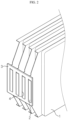
FIGS. 1 and2 are diagrams for illustrating a process of coupling an electrode lead and a bus bar, in manufacturing a conventional battery module. -
FIG. 3 is a diagram showing a battery module manufacturing system with a pressing jig according to an embodiment of the present invention. -
FIG. 4 is a partially enlarged view of the battery module showing that the electrode lead is exposed through a lead slit formed at the bus bar. -
FIG. 5 is a diagram showing that the bus bar is pressed using the pressing jig comprised in a battery module manufacturing system according to an embodiment of the present invention. -
FIG. 6 is a perspective view showing the pressing jig comprised in a battery module manufacturing system according to an embodiment of the present invention. - Hereinafter, preferred embodiments of the present invention will be described in detail with reference to the accompanying drawings. Prior to the description, it should be understood that the terms used in the specification and the appended claims should not be construed as limited to general and dictionary meanings, but interpreted based on the meanings and concepts corresponding to technical aspects of the present invention on the basis of the principle that the inventor is allowed to define terms appropriately for the best explanation. Therefore, the description proposed herein is just a preferable example for the purpose of illustrations only, not intended to limit the scope of the invention, so it should be understood that other equivalents and modifications could be made thereto without departing from the scope of the invention as defined by the appended claims.
- A battery module manufacturing system including a pressing jig according to an embodiment of the invention will be described with reference to
FIGS. 3 to 6 . -
FIG. 3 is a diagram showing a battery module manufacturing system including a pressing jig according to an embodiment of the present invention, andFIG. 4 is a partially enlarged view of the battery module showing that the electrode lead is exposed through a lead slit formed at the bus bar. Also,FIG. 5 is a diagram showing that the bus bar is pressed using the pressing jig of a battery module manufacturing system according to an embodiment of the present invention, andFIG. 6 is a perspective view showing the pressing jig of battery module manufacturing system according to an embodiment of the present invention. - First, referring to
FIGS. 3 to 5 , the battery module manufacturing system according to an embodiment of the present invention is implemented to include abattery module 100 and apressing jig 200 installed at one side thereof. - The
battery module 100 is configured by accommodating a cell stack (seeFIG. 5 ) formed by stacking a plurality ofbattery cells 120 in amodule case 110 and then closing an opening at one side of themodule case 110 by using abus bar assembly 130. - The
battery cells 120 have a pair of electrode leads 121 drawn out in opposite directions. Two or more electrode leads 121 drawn from the plurality ofbattery cells 120 adjacent to each other and extending in the same direction are gathered to form one electrode lead assembly, which is inserted into lead slits S1, S2 formed at abus bar 132, explained later. - The
bus bar assembly 130 includes abus bar frame 131 sized and shaped corresponding to the opening formed at one side of themodule case 110 so that the cell stack may be inserted therein, and a plurality ofbus bars 132 fixedly mounted to thebus bar frame 131 . - The plurality of
bus bars 132 are respectively installed at a plurality of busbar accommodation portions 131a provided at thebus bar frame 131 with a size and shape corresponding to thebus bar 132. - The
bus bar 132 includes afirst bus bar 132a located at the center and asecond bus bar 132b and athird bus bar 132c located at both sides of thefirst bus bar 132a. Thesecond bus bar 132b and thethird bus bar 132c are configured as components separate from thebus bar 132a. - The
first bus bar 132a is installed to be fixed in the busbar accommodation portion 131a of thebus bar frame 131. Thesecond bus bar 132b and thethird bus bar 132c are disposed at both sides of thefirst bus bar 132a inside the busbar accommodation portion 131a and are installed to move toward or away from thebus bar 132a. - The
second bus bar 132b and thethird bus bar 132c are gripped by grippingportions pressing jig 200 inserted into the busbar accommodation portion 131a and move toward thefirst bus bar 132a so that the electrode leads 121 respectively located in the first lead slit S1 formed between thefirst bus bar 132a and thesecond bus bar 132b and the second lead slit S2 formed between thefirst bus bar 132a and thethird bus bar 132c are pressed. - The first electrode lead assembly drawn from the first battery cell group including the plurality of stacked
battery cells 120 and the second electrode lead assembly drawn from the second battery cell group adjacent to the first battery cell group are in contact with thesame bus bar 132, thereby electrically connecting a pair of battery cell groups adjacent to each other. - At this time, the first electrode lead assembly and the second electrode lead assembly have different polarities, and thus the first battery cell group and the second battery cell group adjacent to each other are connected in series.
- That is, the
battery module 100 is configured so that the plurality ofbattery cells 120 of the first battery cell group are connected to each other in parallel, and the plurality of battery cell groups are connected to each other in series. - Even though the figures depict only a case where one battery cell group includes three
battery cells 120 and thus one electrode lead assembly is formed by gathering three electrode leads, the present invention is not limited thereto. - That is, one battery cell group may include two
battery cells 120 or four ormore battery cells 120, and thus one electrode lead assembly may also include two electrode leads 121 or four or more electrode leads 121. - Next, the detailed configuration of the
pressing jig 200 comprised in a battery module manufacturing system according to an embodiment of the present invention will be described with reference toFIGS. 5 and6 . -
FIG. 5 is a diagram showing that the bus bar is pressed using the pressing jig comprised in a battery module manufacturing system according to an embodiment of the present invention, andFIG. 6 is a perspective view showing the pressing jig comprised in a battery module manufacturing system according to an embodiment of the present invention. - Referring to
FIGS. 5 and6 , thepressing jig 200 comprised in a battery module manufacturing system according to an embodiment of the present invention may include afirst frame 210, asecond frame 220, ahinge 230, arestoring member 240, and adistance adjusting knob 250. - The
first frame 210 includes a firstdistance adjusting unit 211 and a firstpressing unit 212, and thesecond frame 220 includes a seconddistance adjusting unit 221 and a secondpressing unit 222. Thefirst frame 210 and thesecond frame 220 are coupled by thehinge 230 so that they may pivot relative to each other. - In an embodiment according to the present invention, based on a portion of the
first frame 210 coupled to thesecond frame 220 by thehinge 230, a portion located at one side is defined as a firstdistance adjusting unit 211, and a portion located at the other side opposite to the above side is defined as a firstpressing unit 212. Similarly, in thesecond frame 220, a portion located at one side based on a portion coupled to thefirst frame 210 by thehinge 230 is defined as a seconddistance adjusting unit 221, and a portion located at the other side opposite to the above side is defined as a secondpressing unit 222. - In a state where the
first frame 210 and thesecond frame 220 are coupled to each other by thehinge 230, the firstdistance adjusting unit 211 and the seconddistance adjusting unit 221 are disposed to face each other, and the firstpressing unit 212 and the secondpressing unit 222 are disposed to face each other. - The
first frame 210 and thesecond frame 220 are coupled by thehinge 230 such that, if the distance between the firstdistance adjusting unit 211 and the seconddistance adjusting unit 221 is decreased, the distance between the firstpressing unit 212 and thesecond pressing unit 222 is increased, and if the distance between the firstdistance adjusting unit 211 and the seconddistance adjusting unit 221 is increased, the distance between the firstpressing unit 212 and the secondpressing unit 222 is decreased. - That is, when using the
pressing jig 200, the user may manipulate thepressing jig 200 so that the distance between the firstdistance adjusting unit 211 and the seconddistance adjusting unit 221 is increased, thereby pressing thebus bar 132 at both sides. - Meanwhile, the first
pressing unit 212 includes a first grippingportion 212a formed at one end thereof so that thebus bar 132 is stably gripped. The firstgripping portion 212a has is a gripping groove G formed in a predetermined depth at a portion in contact with thebus bar 132. - Similarly, the second
pressing unit 222 includes a secondgripping portion 222a formed at one end thereof so that thebus bar 132 is stably gripped. The secondgripping portion 222a has a gripping groove G formed in a predetermined depth at a portion in contact with thebus bar 132. - That is, each of the first
gripping portion 212a and the secondgripping portion 222a have the gripping grooves G formed at the facing surfaces thereof, thereby allowing thesecond bus bar 132b and thethird bus bar 132c being partially inserted and fixed in a stable way. - Referring to
FIGS. 5 and6 along withFIG. 4 , the firstgripping portion 212a and the secondgripping portion 222a are inserted between an inner wall of the busbar accommodating portion 131a and thesecond bus bar 132b and between an inner wall of the busbar accommodating portion 131a and thethird bus bar 132c, respectively, to move thesecond bus bar 132b and thethird bus bar 132c toward thefirst bus bar 132a. - In addition, since the
second bus bar 132b and thethird bus bar 132c are moved as above, the first lead slit S1 and the second lead slit S2 become narrower. As a result, the electrode lead assembly inserted in the first lead slit S1 and the electrode lead assembly inserted in the second lead slit S2 are pressed to closely adhere theelectrode lead 121 and thebus bar 132 to each other. - The restoring
member 240 is a member having an elastic restoring force and connected between thefirst frame 210 and thesecond frame 220. Specifically, both ends of the restoringmember 240 are coupled to afirst fixing portion 211a extended from one end of the firstdistance adjusting unit 211 and asecond fixing portion 221a extending from one end of the seconddistance adjusting unit 221, respectively, and the restoringmember 240 applies a force to the firstdistance adjusting unit 211 and the seconddistance adjusting unit 221 such that the firstdistance adjusting unit 211 and the seconddistance adjusting unit 221 move close to each other. - That is, if no other external force is applied to the first
distance adjusting unit 211 and the seconddistance adjusting unit 221, the firstdistance adjusting unit 211 and the seconddistance adjusting unit 221 are moved toward each other due to the restoringmember 240, and thus, the firstpressing unit 212 and the secondpressing unit 222 are moved away from each other. - The
distance adjusting knob 250 may be implemented to include arotary shaft 251 having a thread formed on at least a portion of an outer circumferential surface thereof and aknob handle 252 connected to one end of therotary shaft 251. - The other end of the
rotary shaft 251, which is opposite to the one end where theknob handle 252 is formed, is pivotally coupled to the firstdistance adjusting unit 211, and therotary shaft 251 is provided through the seconddistance adjusting unit 221. A thread corresponding to the thread formed on therotary shaft 251 is formed on an inner surface of a perforation hole of the seconddistance adjusting unit 221 through which therotary shaft 251 is provided. By doing so, as therotary shaft 251 rotates, the seconddistance adjusting unit 221 moves toward or away from the firstdistance adjusting unit 211. - That is, if the adjusting
knob 250 is rotated along a clockwise direction, the seconddistance adjusting unit 221 moves away from the firstdistance adjusting unit 211, and thus the distance between the firstpressing unit 212 and the secondpressing unit 222 is decreased to press thebus bar 132. On the contrary, if the adjustingknob 250 is rotated along a counterclockwise direction, the seconddistance adjusting unit 221 moves toward the firstdistance adjusting unit 211, and thus the distance between the firstpressing unit 212 and the secondpressing unit 222 is increased, thereby releasing the pressing to thebus bar 132. - Thus, the user of the
pressing jig 200 may rotate thedistance adjusting knob 250 in the clockwise direction in a state where the firstpressing unit 212 and the secondpressing unit 222 are separated wider than the width of thebus bar 132, so that thesecond bus bar 132b and thethird bus bar 132c are moved toward thefirst bus bar 132a, and then perform welding in a state where the electrode leads 121 located in the lead slits S1, S2 are closely adhered to thebus bar 132. - In this case, a welding device may access the
bus bar 132 along the direction indicated by an arrow inFIG. 5 through the space between thefirst frame 210 and thesecond frame 220. - The present invention has been described in detail. However, it should be understood that the detailed description and specific examples, while indicating preferred embodiments of the invention, are given by way of illustration only, since various changes and modifications within the scope of the invention as defined by the appended claims will become apparent to those skilled in the art from this detailed description.
Claims (5)
- A battery module manufacturing system, comprising:a battery module (100) including a cell stack formed by stacking a plurality of battery cells (120),a module case (110) accommodating the cell stack,a bus bar assembly (130) covering an opening formed at one side of the module case (110),wherein the bus bar assembly (130) includes a bus bar frame (131) sized and shaped corresponding to the opening formed at one side of the module case (110), and a plurality of bus bars (132) fixedly mounted to the bus bar frame (131),wherein each one of the plurality of bus bars (132) comprises a first bus bar (132a), a second bus bar (132b), and a third bus bar (132c);a pressing jig (200) installed on the bus bar assembly (130) and configured to press a bus bar (132) of the plurality of bus bars (132) at both sides thereof so that electrode leads (121) located in lead slits (S1, S2) provided between the first bus bar (132a) and the second bus bar (132b) and between the first bus bar (132a) and the third bus bar (132c) are welded to the bus bar (132) in a closely adhered state,wherein the electrode leads (121) are drawn from the plurality of battery cells (120); anda welding device configured to perform welding in a state where the electrode leads located in the lead slits are closely adhered to the bus bar (132),whereinthe pressing jig (200) includes:a first frame (210) having a first distance adjusting unit (211) and a first pressing unit (212); anda second frame (220) having a second distance adjusting unit (221) facing the first distance adjusting unit (211) and a second pressing unit (222) facing the first pressing unit (212), andthe first frame (210) and the second frame (220) are coupled by a hinge so that a distance between first pressing unit (212) and the second pressing unit (222) is increased when a distance between the first distance adjusting unit (211) and the second distance adjusting unit (221) is decreased, and the distance between first pressing unit (212) and the second pressing unit (222) is decreased when the distance between the first distance adjusting unit (211) and the second distance adjusting unit (221) is increased.
- The battery module manufacturing system according to claim 1,
wherein the hinge (230) is configured to connect the first frame (210) and the second frame (220) so that the first frame (210) and the second frame (220) pivot relative to each other. - The battery module manufacturing system according to claim 1,
wherein the pressing jig further includes a restoring member (240) connected between the first distance adjusting unit (211) and the second distance adjusting unit (221) to apply an elastic force to the first distance adjusting unit (211) and the second distance adjusting unit (221) toward each other. - The battery module manufacturing system according to claim 1,
wherein the pressing jig further includes a distance adjusting knob (250) configured to rotate based on a rotary shaft having a thread so that the first frame (210) moves toward or away from the second frame (220). - The battery module manufacturing system according to claim 1,wherein the first pressing unit (212) has a first gripping portion formed at an end thereof;wherein the second pressing unit (222) has a second gripping portion formed at an end thereof; andwherein gripping grooves (G) are respectively formed at facing surfaces of the first gripping portion (212a) and second gripping portion (222a) in a predetermined depth so that the bus bars are inserted therein.
Applications Claiming Priority (2)
| Application Number | Priority Date | Filing Date | Title |
|---|---|---|---|
| KR1020180039231A KR102105665B1 (en) | 2018-04-04 | 2018-04-04 | A pressing jig for pressing a bus bar and a battery module manufacturing system comprising the same |
| PCT/KR2019/002076 WO2019194416A1 (en) | 2018-04-04 | 2019-02-20 | Pressurization jig for pressurizing busbar and battery module manufacturing system comprising same |
Publications (3)
| Publication Number | Publication Date |
|---|---|
| EP3698914A1 EP3698914A1 (en) | 2020-08-26 |
| EP3698914A4 EP3698914A4 (en) | 2021-03-31 |
| EP3698914B1 true EP3698914B1 (en) | 2024-08-28 |
Family
ID=68100930
Family Applications (1)
| Application Number | Title | Priority Date | Filing Date |
|---|---|---|---|
| EP19781991.5A Active EP3698914B1 (en) | 2018-04-04 | 2019-02-20 | Pressurization jig for pressurizing bus bar and battery module manufacturing system comprising same |
Country Status (9)
| Country | Link |
|---|---|
| US (1) | US11660710B2 (en) |
| EP (1) | EP3698914B1 (en) |
| JP (1) | JP7062758B2 (en) |
| KR (1) | KR102105665B1 (en) |
| CN (2) | CN110350136B (en) |
| ES (1) | ES2992941T3 (en) |
| HU (1) | HUE068209T2 (en) |
| PL (1) | PL3698914T3 (en) |
| WO (1) | WO2019194416A1 (en) |
Families Citing this family (19)
| Publication number | Priority date | Publication date | Assignee | Title |
|---|---|---|---|---|
| KR102324264B1 (en) * | 2018-12-21 | 2021-11-08 | 주식회사 엘지에너지솔루션 | A pressing jig apparatus that closely contacts electrode lead with bus bar and a battery module manufacturing system comprising the same |
| KR102836078B1 (en) * | 2019-10-18 | 2025-07-17 | 주식회사 엘지에너지솔루션 | Welding jig |
| KR102688011B1 (en) * | 2019-10-28 | 2024-07-23 | 주식회사 엘지에너지솔루션 | A pressing jig that closely contacts electrode lead with bus bar and laser welding apparatus comprising the same |
| KR102506245B1 (en) | 2019-11-14 | 2023-03-03 | 주식회사 엘지에너지솔루션 | Battery module, method of manufacturing battery module and battery pack including battery module |
| KR102786523B1 (en) | 2019-12-06 | 2025-03-24 | 주식회사 엘지에너지솔루션 | Battery module, battery pack and vehicle comprising the battery module |
| KR102786405B1 (en) * | 2019-12-06 | 2025-03-24 | 주식회사 엘지에너지솔루션 | Battery module, battery pack and vehicle comprising the battery module |
| US11450877B2 (en) * | 2020-03-16 | 2022-09-20 | GM Global Technology Operations LLC | Tooling and method for alignment and assembly of battery module |
| KR20220021439A (en) * | 2020-08-13 | 2022-02-22 | 주식회사 엘지에너지솔루션 | Battery module with improved electrode lead connection structure, and battery pack and vehicle comprising the same |
| JP2024138573A (en) * | 2021-08-26 | 2024-10-09 | Fdk株式会社 | Battery module and manufacturing method thereof |
| JP7798433B2 (en) * | 2021-11-29 | 2026-01-14 | エルジー エナジー ソリューション リミテッド | Electrode tab welding device, electrode tab welding method, and secondary battery |
| EP4481934B1 (en) * | 2022-02-15 | 2026-04-01 | LG Energy Solution, Ltd. | Electrode tab jig assembly and electrode tab welding device comprising same |
| WO2024008369A1 (en) | 2022-07-05 | 2024-01-11 | Robert Bosch Gmbh | An equipment and method to process tabs of pouch cells during assembly of battery packs |
| CN115954620A (en) * | 2022-08-25 | 2023-04-11 | 孚能科技(赣州)股份有限公司 | Cell connectors and battery modules |
| CN117324863A (en) * | 2023-11-15 | 2024-01-02 | 中铁十七局集团城市建设有限公司 | Shaped steel concrete welding positioning device for house construction engineering |
| KR102675359B1 (en) * | 2024-03-04 | 2024-06-14 | 신영기공 주식회사 | Jig for fixing |
| JP7741919B1 (en) * | 2024-03-29 | 2025-09-18 | 本田技研工業株式会社 | Busbar clamping device |
| JP7742445B1 (en) * | 2024-03-29 | 2025-09-19 | 本田技研工業株式会社 | Busbar clamping device and busbar clamping method |
| KR102816825B1 (en) * | 2024-07-15 | 2025-06-05 | 하이쎄미코(주) | Jig for electroplating of glass substrates |
| KR102859397B1 (en) * | 2025-02-23 | 2025-09-15 | 윤지영 | Laser welding device for cell lead connection |
Family Cites Families (47)
| Publication number | Priority date | Publication date | Assignee | Title |
|---|---|---|---|---|
| US1752143A (en) * | 1927-12-17 | 1930-03-25 | Walter A Bishman | Storage-battery carrier |
| US2003629A (en) * | 1931-02-13 | 1935-06-04 | Irven E Coffey | In and out terminal cleaning tool |
| US2419270A (en) * | 1944-07-07 | 1947-04-22 | John G Linnartz | Parallel screw clamp |
| US2737917A (en) * | 1952-07-11 | 1956-03-13 | Rome Cable Corp | Device for positioning and straightening wire ends and the like |
| US2969448A (en) * | 1959-03-03 | 1961-01-24 | Continental Can Co | Heater vaporizer element support |
| CH569197A5 (en) * | 1972-11-10 | 1975-11-14 | Reist Walter | |
| US3874443A (en) * | 1973-07-16 | 1975-04-01 | Joseph V Bayer | Heat dissipator |
| US4034202A (en) * | 1975-05-23 | 1977-07-05 | Nu-Concept Computer Systems, Inc. | Integrated circuit pack extractor |
| JPS52109124A (en) | 1976-03-08 | 1977-09-13 | Yuasa Battery Co Ltd | Device for producing battery |
| US4281568A (en) * | 1979-06-08 | 1981-08-04 | Martinmaas Werner W | Quickly adjustable ratchet wrench |
| US4777779A (en) * | 1983-08-22 | 1988-10-18 | Meteor Manufacturing & Machinery Co. | Pipet plugging machine |
| DE4026771A1 (en) * | 1990-08-24 | 1992-02-27 | Ralph Roeser | Mechanical automatic gearing for separating or gripping tool - comprise series of interrelated pivoted and spring loaded levers |
| US5046958A (en) * | 1990-12-07 | 1991-09-10 | Ronald Brown | Welding ground clamp |
| GB2282757B (en) * | 1993-10-07 | 1997-09-24 | Walker Lindsey Julia Jane | Hair piece |
| SE9603581L (en) * | 1996-10-01 | 1998-04-02 | Fast Industriprodukter Hb | Hand tool locking device |
| JP2000067843A (en) | 1998-08-24 | 2000-03-03 | Toyota Motor Corp | Collective battery |
| US7007357B2 (en) * | 2001-06-07 | 2006-03-07 | Iwata Denko Co., Ltd. | Removal and installation device for external and internal snap rings |
| US6899262B2 (en) * | 2003-05-19 | 2005-05-31 | Asm Technology Singapore Pte Ltd | Clamping device |
| JP4829587B2 (en) * | 2005-10-14 | 2011-12-07 | 日本電気株式会社 | Electrical device assembly and manufacturing method thereof |
| US7549569B2 (en) * | 2006-06-29 | 2009-06-23 | Asm Technology Singapore Pte Ltd. | Wire clamp gap control mechanism and method |
| JP2008183625A (en) * | 2008-05-08 | 2008-08-14 | Obara Corp | X type welding machine |
| CN201632992U (en) * | 2010-02-25 | 2010-11-17 | 浙江吉利汽车研究院有限公司 | a snap ring pliers |
| CN201838740U (en) * | 2010-09-30 | 2011-05-18 | 江苏省电力公司江都市供电公司 | Jaw type clamp grounding wire |
| WO2012148100A2 (en) | 2011-04-26 | 2012-11-01 | 주식회사 엘지화학 | Bus bar having a novel structure, and battery module including same |
| CN202129733U (en) * | 2011-06-01 | 2012-02-01 | 福建亚亨动力科技集团有限公司 | A clamp for storage battery busbar cast welding repair |
| WO2013059242A2 (en) * | 2011-10-18 | 2013-04-25 | American Grease Stick Company | Tool for coupling fluid lines |
| AT512069B1 (en) | 2011-10-31 | 2016-01-15 | Fronius Int Gmbh | RESISTANCE WELDING DEVICE |
| KR20130049984A (en) * | 2011-11-07 | 2013-05-15 | 아이피지 포토닉스 코리아(주) | Bus bar for battery and battery module |
| KR101298849B1 (en) | 2011-12-28 | 2013-08-23 | 에이치엘그린파워 주식회사 | Housing structure of Battery module |
| DE102012219127B3 (en) * | 2012-10-19 | 2014-01-02 | Trumpf Sachsen Gmbh | Device for handling workpieces, in particular of machining products of a cutting sheet metal working, as well as mechanical arrangements with such a device |
| KR101417412B1 (en) | 2012-11-16 | 2014-07-09 | 세방전지(주) | Connecting apparatus for battery pack |
| KR20140005849U (en) | 2013-05-09 | 2014-11-19 | 이병호 | Feeding device for structure material |
| WO2015007255A1 (en) * | 2013-07-17 | 2015-01-22 | Ersa Gmbh | Conveyor device for printed circuit boards |
| GB2520704B (en) * | 2013-11-28 | 2015-10-14 | Yuan-Yu Wang | Snap ring pliers with ratchet and locking member |
| KR101750597B1 (en) | 2014-04-30 | 2017-06-23 | 주식회사 엘지화학 | Laser welding apparatus |
| KR101794944B1 (en) * | 2014-08-06 | 2017-11-07 | 주식회사 엘지화학 | Welding Stick Jig |
| KR101809689B1 (en) | 2014-11-11 | 2017-12-15 | 주식회사 엘지화학 | Pressing zig for secondary battery cell |
| KR101693790B1 (en) * | 2015-01-13 | 2017-01-23 | 두산중공업 주식회사 | Jig for handling work piece |
| CN204524653U (en) | 2015-03-19 | 2015-08-05 | 中航锂电(洛阳)有限公司 | A kind of fast locking device of battery pole ear and battery pole ear weld jig |
| KR102034208B1 (en) | 2016-03-03 | 2019-10-18 | 주식회사 엘지화학 | Battery module, battery pack the battery module and vehicle comprising the battery pack |
| KR102101429B1 (en) * | 2016-05-18 | 2020-04-16 | 주식회사 엘지화학 | Lead welding apparatus, battery module manufactured by the lead welding apparatus and battery pack comprising the battery module |
| KR102235650B1 (en) | 2016-06-17 | 2021-04-01 | 에스케이이노베이션 주식회사 | Secondary battery module, and secondary battery pack including the same |
| KR20180039231A (en) | 2016-10-07 | 2018-04-18 | 삼성디스플레이 주식회사 | Display device and fabrication method of display device |
| CN107175595B (en) * | 2017-05-16 | 2018-08-14 | 安徽世绿环保科技有限公司 | A kind of Clean- vibration damping securing supports of pipeline processing |
| KR102313030B1 (en) * | 2018-06-29 | 2021-10-13 | 주식회사 엘지에너지솔루션 | Automatic pressing jig apparatus that closely contacts electrode lead with bus bar |
| KR102722638B1 (en) * | 2019-03-26 | 2024-10-25 | 주식회사 엘지에너지솔루션 | Battery module and method of manufacturing the same |
| CN113370090A (en) * | 2021-07-23 | 2021-09-10 | 青岛可恩口腔医院有限公司 | Special arch wire tempering forming pliers for dental spot welding machine |
-
2018
- 2018-04-04 KR KR1020180039231A patent/KR102105665B1/en active Active
-
2019
- 2019-02-20 ES ES19781991T patent/ES2992941T3/en active Active
- 2019-02-20 US US16/766,934 patent/US11660710B2/en active Active
- 2019-02-20 JP JP2020519771A patent/JP7062758B2/en active Active
- 2019-02-20 HU HUE19781991A patent/HUE068209T2/en unknown
- 2019-02-20 PL PL19781991.5T patent/PL3698914T3/en unknown
- 2019-02-20 WO PCT/KR2019/002076 patent/WO2019194416A1/en not_active Ceased
- 2019-02-20 EP EP19781991.5A patent/EP3698914B1/en active Active
- 2019-04-04 CN CN201910270049.1A patent/CN110350136B/en active Active
- 2019-04-04 CN CN201920459733.XU patent/CN210120183U/en active Active
Also Published As
| Publication number | Publication date |
|---|---|
| US11660710B2 (en) | 2023-05-30 |
| CN210120183U (en) | 2020-02-28 |
| US20200368855A1 (en) | 2020-11-26 |
| JP7062758B2 (en) | 2022-05-06 |
| KR20190115939A (en) | 2019-10-14 |
| PL3698914T3 (en) | 2024-12-16 |
| CN110350136A (en) | 2019-10-18 |
| EP3698914A1 (en) | 2020-08-26 |
| KR102105665B1 (en) | 2020-05-29 |
| ES2992941T3 (en) | 2024-12-20 |
| CN110350136B (en) | 2020-11-17 |
| WO2019194416A1 (en) | 2019-10-10 |
| JP2020536365A (en) | 2020-12-10 |
| EP3698914A4 (en) | 2021-03-31 |
| HUE068209T2 (en) | 2024-12-28 |
Similar Documents
| Publication | Publication Date | Title |
|---|---|---|
| EP3698914B1 (en) | Pressurization jig for pressurizing bus bar and battery module manufacturing system comprising same | |
| EP3836248B1 (en) | Battery module including foldable side plate and method for manufacturing same | |
| JP5491712B2 (en) | Automotive high voltage battery | |
| ES3032736T3 (en) | Battery module having bus bar assembly | |
| EP2390945B1 (en) | Battery module | |
| US20120189899A1 (en) | Secondary battery, secondary battery manufacturing device, and secondary battery manufacturing method | |
| EP3836252A1 (en) | Pressure jig apparatus for bringing electrode lead into close contact with bus bar and battery module manufacturing system including same | |
| JP5279697B2 (en) | Secondary battery | |
| JP2023038347A (en) | Battery tab structure | |
| EP2487738A1 (en) | Electrode assembly and secondary battery using the same | |
| EP4393630A1 (en) | Welding device, welding method and electrode assembly | |
| EP3944407B1 (en) | Battery module | |
| EP3828957B1 (en) | Battery module having insulation pad with extended length, and battery pack and vehicle comprising same | |
| EP4020696A1 (en) | Connection member connected to electrode lead by physical coupling, and battery cell stack comprising same | |
| KR102701469B1 (en) | A pressing jig for pressing a bus bar and a battery module manufacturing system comprising the same | |
| US20150263317A1 (en) | Secondary battery pack | |
| JP5832819B2 (en) | Assembled battery | |
| JP2019091563A (en) | Power storage element | |
| EP4109663A1 (en) | Battery module comprising busbar having threaded portion | |
| EP4700970A1 (en) | Method for bending lead of battery | |
| EP4087029A1 (en) | Pouch-type secondary battery and method for manufacturing secondary battery |
Legal Events
| Date | Code | Title | Description |
|---|---|---|---|
| STAA | Information on the status of an ep patent application or granted ep patent |
Free format text: STATUS: THE INTERNATIONAL PUBLICATION HAS BEEN MADE |
|
| PUAI | Public reference made under article 153(3) epc to a published international application that has entered the european phase |
Free format text: ORIGINAL CODE: 0009012 |
|
| STAA | Information on the status of an ep patent application or granted ep patent |
Free format text: STATUS: REQUEST FOR EXAMINATION WAS MADE |
|
| 17P | Request for examination filed |
Effective date: 20200520 |
|
| AK | Designated contracting states |
Kind code of ref document: A1 Designated state(s): AL AT BE BG CH CY CZ DE DK EE ES FI FR GB GR HR HU IE IS IT LI LT LU LV MC MK MT NL NO PL PT RO RS SE SI SK SM TR |
|
| AX | Request for extension of the european patent |
Extension state: BA ME |
|
| RIN1 | Information on inventor provided before grant (corrected) |
Inventor name: CHI, HO-JUNE Inventor name: LEE, JUNG-HOON Inventor name: MUN, JEONG-O Inventor name: KIM, KYUNG-MO Inventor name: PARK, JIN-YONG |
|
| A4 | Supplementary search report drawn up and despatched |
Effective date: 20210301 |
|
| RIC1 | Information provided on ipc code assigned before grant |
Ipc: H01M 50/536 20210101ALI20210223BHEP Ipc: B25B 5/06 20060101ALI20210223BHEP Ipc: B23K 37/04 20060101AFI20210223BHEP Ipc: B25B 5/04 20060101ALI20210223BHEP Ipc: B23K 31/02 20060101ALI20210223BHEP Ipc: B25B 5/14 20060101ALI20210223BHEP Ipc: H01M 50/204 20210101ALI20210223BHEP Ipc: B23K 101/38 20060101ALI20210223BHEP |
|
| DAV | Request for validation of the european patent (deleted) | ||
| DAX | Request for extension of the european patent (deleted) | ||
| RAP1 | Party data changed (applicant data changed or rights of an application transferred) |
Owner name: LG ENERGY SOLUTION LTD. |
|
| RAP3 | Party data changed (applicant data changed or rights of an application transferred) |
Owner name: LG ENERGY SOLUTION, LTD. |
|
| STAA | Information on the status of an ep patent application or granted ep patent |
Free format text: STATUS: EXAMINATION IS IN PROGRESS |
|
| 17Q | First examination report despatched |
Effective date: 20220711 |
|
| GRAP | Despatch of communication of intention to grant a patent |
Free format text: ORIGINAL CODE: EPIDOSNIGR1 |
|
| STAA | Information on the status of an ep patent application or granted ep patent |
Free format text: STATUS: GRANT OF PATENT IS INTENDED |
|
| INTG | Intention to grant announced |
Effective date: 20240321 |
|
| P01 | Opt-out of the competence of the unified patent court (upc) registered |
Effective date: 20240404 |
|
| GRAS | Grant fee paid |
Free format text: ORIGINAL CODE: EPIDOSNIGR3 |
|
| GRAA | (expected) grant |
Free format text: ORIGINAL CODE: 0009210 |
|
| STAA | Information on the status of an ep patent application or granted ep patent |
Free format text: STATUS: THE PATENT HAS BEEN GRANTED |
|
| AK | Designated contracting states |
Kind code of ref document: B1 Designated state(s): AL AT BE BG CH CY CZ DE DK EE ES FI FR GB GR HR HU IE IS IT LI LT LU LV MC MK MT NL NO PL PT RO RS SE SI SK SM TR |
|
| REG | Reference to a national code |
Ref country code: GB Ref legal event code: FG4D |
|
| REG | Reference to a national code |
Ref country code: CH Ref legal event code: EP |
|
| REG | Reference to a national code |
Ref country code: NL Ref legal event code: FP |
|
| REG | Reference to a national code |
Ref country code: DE Ref legal event code: R096 Ref document number: 602019057938 Country of ref document: DE |
|
| REG | Reference to a national code |
Ref country code: IE Ref legal event code: FG4D |
|
| REG | Reference to a national code |
Ref country code: SE Ref legal event code: TRGR |
|
| REG | Reference to a national code |
Ref country code: ES Ref legal event code: FG2A Ref document number: 2992941 Country of ref document: ES Kind code of ref document: T3 Effective date: 20241220 |
|
| REG | Reference to a national code |
Ref country code: LT Ref legal event code: MG9D |
|
| REG | Reference to a national code |
Ref country code: HU Ref legal event code: AG4A Ref document number: E068209 Country of ref document: HU |
|
| PG25 | Lapsed in a contracting state [announced via postgrant information from national office to epo] |
Ref country code: NO Free format text: LAPSE BECAUSE OF FAILURE TO SUBMIT A TRANSLATION OF THE DESCRIPTION OR TO PAY THE FEE WITHIN THE PRESCRIBED TIME-LIMIT Effective date: 20241128 |
|
| REG | Reference to a national code |
Ref country code: AT Ref legal event code: MK05 Ref document number: 1717432 Country of ref document: AT Kind code of ref document: T Effective date: 20240828 |
|
| PG25 | Lapsed in a contracting state [announced via postgrant information from national office to epo] |
Ref country code: PT Free format text: LAPSE BECAUSE OF FAILURE TO SUBMIT A TRANSLATION OF THE DESCRIPTION OR TO PAY THE FEE WITHIN THE PRESCRIBED TIME-LIMIT Effective date: 20241230 Ref country code: FI Free format text: LAPSE BECAUSE OF FAILURE TO SUBMIT A TRANSLATION OF THE DESCRIPTION OR TO PAY THE FEE WITHIN THE PRESCRIBED TIME-LIMIT Effective date: 20240828 Ref country code: GR Free format text: LAPSE BECAUSE OF FAILURE TO SUBMIT A TRANSLATION OF THE DESCRIPTION OR TO PAY THE FEE WITHIN THE PRESCRIBED TIME-LIMIT Effective date: 20241129 |
|
| PG25 | Lapsed in a contracting state [announced via postgrant information from national office to epo] |
Ref country code: BG Free format text: LAPSE BECAUSE OF FAILURE TO SUBMIT A TRANSLATION OF THE DESCRIPTION OR TO PAY THE FEE WITHIN THE PRESCRIBED TIME-LIMIT Effective date: 20240828 |
|
| PG25 | Lapsed in a contracting state [announced via postgrant information from national office to epo] |
Ref country code: LV Free format text: LAPSE BECAUSE OF FAILURE TO SUBMIT A TRANSLATION OF THE DESCRIPTION OR TO PAY THE FEE WITHIN THE PRESCRIBED TIME-LIMIT Effective date: 20240828 |
|
| PG25 | Lapsed in a contracting state [announced via postgrant information from national office to epo] |
Ref country code: IS Free format text: LAPSE BECAUSE OF FAILURE TO SUBMIT A TRANSLATION OF THE DESCRIPTION OR TO PAY THE FEE WITHIN THE PRESCRIBED TIME-LIMIT Effective date: 20241228 Ref country code: AT Free format text: LAPSE BECAUSE OF FAILURE TO SUBMIT A TRANSLATION OF THE DESCRIPTION OR TO PAY THE FEE WITHIN THE PRESCRIBED TIME-LIMIT Effective date: 20240828 |
|
| PG25 | Lapsed in a contracting state [announced via postgrant information from national office to epo] |
Ref country code: HR Free format text: LAPSE BECAUSE OF FAILURE TO SUBMIT A TRANSLATION OF THE DESCRIPTION OR TO PAY THE FEE WITHIN THE PRESCRIBED TIME-LIMIT Effective date: 20240828 |
|
| PG25 | Lapsed in a contracting state [announced via postgrant information from national office to epo] |
Ref country code: RS Free format text: LAPSE BECAUSE OF FAILURE TO SUBMIT A TRANSLATION OF THE DESCRIPTION OR TO PAY THE FEE WITHIN THE PRESCRIBED TIME-LIMIT Effective date: 20241128 |
|
| PG25 | Lapsed in a contracting state [announced via postgrant information from national office to epo] |
Ref country code: RS Free format text: LAPSE BECAUSE OF FAILURE TO SUBMIT A TRANSLATION OF THE DESCRIPTION OR TO PAY THE FEE WITHIN THE PRESCRIBED TIME-LIMIT Effective date: 20241128 Ref country code: PT Free format text: LAPSE BECAUSE OF FAILURE TO SUBMIT A TRANSLATION OF THE DESCRIPTION OR TO PAY THE FEE WITHIN THE PRESCRIBED TIME-LIMIT Effective date: 20241230 Ref country code: NO Free format text: LAPSE BECAUSE OF FAILURE TO SUBMIT A TRANSLATION OF THE DESCRIPTION OR TO PAY THE FEE WITHIN THE PRESCRIBED TIME-LIMIT Effective date: 20241128 Ref country code: LV Free format text: LAPSE BECAUSE OF FAILURE TO SUBMIT A TRANSLATION OF THE DESCRIPTION OR TO PAY THE FEE WITHIN THE PRESCRIBED TIME-LIMIT Effective date: 20240828 Ref country code: IS Free format text: LAPSE BECAUSE OF FAILURE TO SUBMIT A TRANSLATION OF THE DESCRIPTION OR TO PAY THE FEE WITHIN THE PRESCRIBED TIME-LIMIT Effective date: 20241228 Ref country code: HR Free format text: LAPSE BECAUSE OF FAILURE TO SUBMIT A TRANSLATION OF THE DESCRIPTION OR TO PAY THE FEE WITHIN THE PRESCRIBED TIME-LIMIT Effective date: 20240828 Ref country code: GR Free format text: LAPSE BECAUSE OF FAILURE TO SUBMIT A TRANSLATION OF THE DESCRIPTION OR TO PAY THE FEE WITHIN THE PRESCRIBED TIME-LIMIT Effective date: 20241129 Ref country code: FI Free format text: LAPSE BECAUSE OF FAILURE TO SUBMIT A TRANSLATION OF THE DESCRIPTION OR TO PAY THE FEE WITHIN THE PRESCRIBED TIME-LIMIT Effective date: 20240828 Ref country code: BG Free format text: LAPSE BECAUSE OF FAILURE TO SUBMIT A TRANSLATION OF THE DESCRIPTION OR TO PAY THE FEE WITHIN THE PRESCRIBED TIME-LIMIT Effective date: 20240828 Ref country code: AT Free format text: LAPSE BECAUSE OF FAILURE TO SUBMIT A TRANSLATION OF THE DESCRIPTION OR TO PAY THE FEE WITHIN THE PRESCRIBED TIME-LIMIT Effective date: 20240828 |
|
| PG25 | Lapsed in a contracting state [announced via postgrant information from national office to epo] |
Ref country code: SM Free format text: LAPSE BECAUSE OF FAILURE TO SUBMIT A TRANSLATION OF THE DESCRIPTION OR TO PAY THE FEE WITHIN THE PRESCRIBED TIME-LIMIT Effective date: 20240828 Ref country code: DK Free format text: LAPSE BECAUSE OF FAILURE TO SUBMIT A TRANSLATION OF THE DESCRIPTION OR TO PAY THE FEE WITHIN THE PRESCRIBED TIME-LIMIT Effective date: 20240828 Ref country code: RO Free format text: LAPSE BECAUSE OF FAILURE TO SUBMIT A TRANSLATION OF THE DESCRIPTION OR TO PAY THE FEE WITHIN THE PRESCRIBED TIME-LIMIT Effective date: 20240828 |
|
| PG25 | Lapsed in a contracting state [announced via postgrant information from national office to epo] |
Ref country code: EE Free format text: LAPSE BECAUSE OF FAILURE TO SUBMIT A TRANSLATION OF THE DESCRIPTION OR TO PAY THE FEE WITHIN THE PRESCRIBED TIME-LIMIT Effective date: 20240828 |
|
| PG25 | Lapsed in a contracting state [announced via postgrant information from national office to epo] |
Ref country code: CZ Free format text: LAPSE BECAUSE OF FAILURE TO SUBMIT A TRANSLATION OF THE DESCRIPTION OR TO PAY THE FEE WITHIN THE PRESCRIBED TIME-LIMIT Effective date: 20240828 |
|
| PG25 | Lapsed in a contracting state [announced via postgrant information from national office to epo] |
Ref country code: SK Free format text: LAPSE BECAUSE OF FAILURE TO SUBMIT A TRANSLATION OF THE DESCRIPTION OR TO PAY THE FEE WITHIN THE PRESCRIBED TIME-LIMIT Effective date: 20240828 |
|
| REG | Reference to a national code |
Ref country code: DE Ref legal event code: R097 Ref document number: 602019057938 Country of ref document: DE |
|
| PLBE | No opposition filed within time limit |
Free format text: ORIGINAL CODE: 0009261 |
|
| STAA | Information on the status of an ep patent application or granted ep patent |
Free format text: STATUS: NO OPPOSITION FILED WITHIN TIME LIMIT |
|
| 26N | No opposition filed |
Effective date: 20250530 |
|
| PG25 | Lapsed in a contracting state [announced via postgrant information from national office to epo] |
Ref country code: MC Free format text: LAPSE BECAUSE OF FAILURE TO SUBMIT A TRANSLATION OF THE DESCRIPTION OR TO PAY THE FEE WITHIN THE PRESCRIBED TIME-LIMIT Effective date: 20240828 |
|
| REG | Reference to a national code |
Ref country code: CH Ref legal event code: PL |
|
| PG25 | Lapsed in a contracting state [announced via postgrant information from national office to epo] |
Ref country code: LU Free format text: LAPSE BECAUSE OF NON-PAYMENT OF DUE FEES Effective date: 20250220 |
|
| PG25 | Lapsed in a contracting state [announced via postgrant information from national office to epo] |
Ref country code: CH Free format text: LAPSE BECAUSE OF NON-PAYMENT OF DUE FEES Effective date: 20250228 |
|
| PG25 | Lapsed in a contracting state [announced via postgrant information from national office to epo] |
Ref country code: IE Free format text: LAPSE BECAUSE OF NON-PAYMENT OF DUE FEES Effective date: 20250220 |
|
| PGFP | Annual fee paid to national office [announced via postgrant information from national office to epo] |
Ref country code: NL Payment date: 20260121 Year of fee payment: 8 |
|
| PGFP | Annual fee paid to national office [announced via postgrant information from national office to epo] |
Ref country code: HU Payment date: 20260227 Year of fee payment: 8 |
|
| PGFP | Annual fee paid to national office [announced via postgrant information from national office to epo] |
Ref country code: SE Payment date: 20260121 Year of fee payment: 8 |
|
| PGFP | Annual fee paid to national office [announced via postgrant information from national office to epo] |
Ref country code: GB Payment date: 20260122 Year of fee payment: 8 |
|
| PGFP | Annual fee paid to national office [announced via postgrant information from national office to epo] |
Ref country code: ES Payment date: 20260324 Year of fee payment: 8 |
|
| PGFP | Annual fee paid to national office [announced via postgrant information from national office to epo] |
Ref country code: DE Payment date: 20260120 Year of fee payment: 8 |
|
| PGFP | Annual fee paid to national office [announced via postgrant information from national office to epo] |
Ref country code: BE Payment date: 20260121 Year of fee payment: 8 Ref country code: IT Payment date: 20260121 Year of fee payment: 8 |
|
| PGFP | Annual fee paid to national office [announced via postgrant information from national office to epo] |
Ref country code: FR Payment date: 20260121 Year of fee payment: 8 |
|
| PGFP | Annual fee paid to national office [announced via postgrant information from national office to epo] |
Ref country code: TR Payment date: 20260121 Year of fee payment: 8 |
|
| PGFP | Annual fee paid to national office [announced via postgrant information from national office to epo] |
Ref country code: PL Payment date: 20260120 Year of fee payment: 8 |