EP3698901A1 - A press tool - Google Patents
A press tool Download PDFInfo
- Publication number
- EP3698901A1 EP3698901A1 EP19157928.3A EP19157928A EP3698901A1 EP 3698901 A1 EP3698901 A1 EP 3698901A1 EP 19157928 A EP19157928 A EP 19157928A EP 3698901 A1 EP3698901 A1 EP 3698901A1
- Authority
- EP
- European Patent Office
- Prior art keywords
- die
- leg
- die member
- press tool
- corner
- Prior art date
- Legal status (The legal status is an assumption and is not a legal conclusion. Google has not performed a legal analysis and makes no representation as to the accuracy of the status listed.)
- Granted
Links
Images


Classifications
-
- B—PERFORMING OPERATIONS; TRANSPORTING
- B22—CASTING; POWDER METALLURGY
- B22F—WORKING METALLIC POWDER; MANUFACTURE OF ARTICLES FROM METALLIC POWDER; MAKING METALLIC POWDER; APPARATUS OR DEVICES SPECIALLY ADAPTED FOR METALLIC POWDER
- B22F3/00—Manufacture of workpieces or articles from metallic powder characterised by the manner of compacting or sintering; Apparatus specially adapted therefor ; Presses and furnaces
- B22F3/02—Compacting only
- B22F3/03—Press-moulding apparatus therefor
-
- B—PERFORMING OPERATIONS; TRANSPORTING
- B22—CASTING; POWDER METALLURGY
- B22F—WORKING METALLIC POWDER; MANUFACTURE OF ARTICLES FROM METALLIC POWDER; MAKING METALLIC POWDER; APPARATUS OR DEVICES SPECIALLY ADAPTED FOR METALLIC POWDER
- B22F7/00—Manufacture of composite layers, workpieces, or articles, comprising metallic powder, by sintering the powder, with or without compacting wherein at least one part is obtained by sintering or compression
- B22F7/06—Manufacture of composite layers, workpieces, or articles, comprising metallic powder, by sintering the powder, with or without compacting wherein at least one part is obtained by sintering or compression of composite workpieces or articles from parts, e.g. to form tipped tools
-
- B—PERFORMING OPERATIONS; TRANSPORTING
- B22—CASTING; POWDER METALLURGY
- B22F—WORKING METALLIC POWDER; MANUFACTURE OF ARTICLES FROM METALLIC POWDER; MAKING METALLIC POWDER; APPARATUS OR DEVICES SPECIALLY ADAPTED FOR METALLIC POWDER
- B22F7/00—Manufacture of composite layers, workpieces, or articles, comprising metallic powder, by sintering the powder, with or without compacting wherein at least one part is obtained by sintering or compression
- B22F7/06—Manufacture of composite layers, workpieces, or articles, comprising metallic powder, by sintering the powder, with or without compacting wherein at least one part is obtained by sintering or compression of composite workpieces or articles from parts, e.g. to form tipped tools
- B22F7/062—Manufacture of composite layers, workpieces, or articles, comprising metallic powder, by sintering the powder, with or without compacting wherein at least one part is obtained by sintering or compression of composite workpieces or articles from parts, e.g. to form tipped tools involving the connection or repairing of preformed parts
-
- B—PERFORMING OPERATIONS; TRANSPORTING
- B30—PRESSES
- B30B—PRESSES IN GENERAL
- B30B11/00—Presses specially adapted for forming shaped articles from material in particulate or plastic state, e.g. briquetting presses, tabletting presses
- B30B11/007—Presses specially adapted for forming shaped articles from material in particulate or plastic state, e.g. briquetting presses, tabletting presses using a plurality of pressing members working in different directions
-
- B—PERFORMING OPERATIONS; TRANSPORTING
- B30—PRESSES
- B30B—PRESSES IN GENERAL
- B30B15/00—Details of, or accessories for, presses; Auxiliary measures in connection with pressing
- B30B15/02—Dies; Inserts therefor; Mounting thereof; Moulds
- B30B15/022—Moulds for compacting material in powder, granular of pasta form
-
- C—CHEMISTRY; METALLURGY
- C22—METALLURGY; FERROUS OR NON-FERROUS ALLOYS; TREATMENT OF ALLOYS OR NON-FERROUS METALS
- C22C—ALLOYS
- C22C29/00—Alloys based on carbides, oxides, nitrides, borides, or silicides, e.g. cermets, or other metal compounds, e.g. oxynitrides, sulfides
- C22C29/02—Alloys based on carbides, oxides, nitrides, borides, or silicides, e.g. cermets, or other metal compounds, e.g. oxynitrides, sulfides based on carbides or carbonitrides
- C22C29/06—Alloys based on carbides, oxides, nitrides, borides, or silicides, e.g. cermets, or other metal compounds, e.g. oxynitrides, sulfides based on carbides or carbonitrides based on carbides, but not containing other metal compounds
-
- C—CHEMISTRY; METALLURGY
- C22—METALLURGY; FERROUS OR NON-FERROUS ALLOYS; TREATMENT OF ALLOYS OR NON-FERROUS METALS
- C22C—ALLOYS
- C22C29/00—Alloys based on carbides, oxides, nitrides, borides, or silicides, e.g. cermets, or other metal compounds, e.g. oxynitrides, sulfides
- C22C29/02—Alloys based on carbides, oxides, nitrides, borides, or silicides, e.g. cermets, or other metal compounds, e.g. oxynitrides, sulfides based on carbides or carbonitrides
- C22C29/06—Alloys based on carbides, oxides, nitrides, borides, or silicides, e.g. cermets, or other metal compounds, e.g. oxynitrides, sulfides based on carbides or carbonitrides based on carbides, but not containing other metal compounds
- C22C29/08—Alloys based on carbides, oxides, nitrides, borides, or silicides, e.g. cermets, or other metal compounds, e.g. oxynitrides, sulfides based on carbides or carbonitrides based on carbides, but not containing other metal compounds based on tungsten carbide
-
- B—PERFORMING OPERATIONS; TRANSPORTING
- B22—CASTING; POWDER METALLURGY
- B22F—WORKING METALLIC POWDER; MANUFACTURE OF ARTICLES FROM METALLIC POWDER; MAKING METALLIC POWDER; APPARATUS OR DEVICES SPECIALLY ADAPTED FOR METALLIC POWDER
- B22F3/00—Manufacture of workpieces or articles from metallic powder characterised by the manner of compacting or sintering; Apparatus specially adapted therefor ; Presses and furnaces
- B22F3/02—Compacting only
- B22F3/03—Press-moulding apparatus therefor
- B22F2003/031—Press-moulding apparatus therefor with punches moving in different directions in different planes
Definitions
- the present disclosure relates to a press tool for manufacturing a cutting insert green body.
- Cutting inserts are metal cutting tools for machining of metal by milling, drilling or turning or by similar chip forming methods.
- Cutting inserts are produced by powder metallurgical methods from a metallic composite powder, for example, a cemented carbide powder, or from a ceramic powder, such as a mixture comprising aluminium oxide and silicon nitride.
- a cemented carbide is a metallic composite having metal carbides, for example, tungsten carbide, titanium carbide or tantalum carbide in a metallic binder of, for example, cobalt, nickel or iron.
- Cutting inserts may also be manufactured from cermets, for example, from a mixture comprising titanium carbide and nickel, or other materials such as, for example, cBN materials.
- the powder may be compacted into a cutting insert green body by opposing first and second punches in a die cavity. After compaction, the cutting insert green body is removed from the die cavity and sintered into a solid cutting insert blank.
- the die used for housing the powder in connection to the compaction may be a so called split die press tool, comprising a first and a second die half that are movable from each other for the purpose of allowing removal of a geometrically complicated green body from the die after compaction thereof.
- the die halves may be of different shape.
- each die half comprises a body having a u-shaped recess at an end thereof. Two sides of the U-shaped recess may be regarded as defined by two rectangular parallelepiped shaped legs extending from the rest of the body of the die half.
- each die half comprises a body having a v-shaped recess at an end thereof.
- the two sides of the v-shaped recess may be regarded as defined by two wedge shaped legs extending from the rest of the body of the die half.
- two die-halves are positioned with their respective v-shaped recess directed towards each other, such that a die cavity is defined by the opposing recesses.
- a lower punch or die element is arranged at the bottom of the die cavity, powder is introduced into the die cavity, and an upper punch, introduced from above into said die cavity, is used for compacting the powder, in combination with a corresponding introduction from below of the lower punch into the die cavity.
- the powder will exert an outwardly directed pressure on the legs of the respective die half striving to bend the legs in an outward direction.
- die halves made of cemented carbide of grades having the requested wear resistance for the application in question may obtain cracks in a corner region of the die member where two die surfaces meet each other after repeated compaction sequences, due to the legs being bend in an outward direction during each compaction sequence.
- cracks are formed in the corner region before the inner surfaces of the legs are worn to a non-acceptable standard due to the abrasion caused by the powder.
- crack initiation and propagation in the corner region of the respective die half becomes the critical factor for the functionality of the press tool.
- a press tool for manufacturing a cutting insert green body comprising:
- the diverse die material properties may be achieved by means of a method in which different parts made of sintered cemented carbide of different microstructure and/or composition are sintered together into a single body, followed by forming of a recess by means of electro discharge machining, such that a die having the geometry and cavity as defined above is formed.
- the cemented carbide having the lower toughness has higher wear resistance than the tougher portion.
- the first and second surfaces of the first and second legs are formed by the cemented carbide having the lower toughness and the higher wear resistance.
- said corner has an angle ⁇ of less than 100o.
- said corner has an angle ⁇ of less than 70o.
- the corner in said corner region has a corner curvature corresponding to a radius of less than 1.65 mm, preferably less than 1.1 mm.
- At least one of said two meeting surfaces is one of said first and second die surface.
- said two meeting surfaces are said first and second die surfaces.
- said portion extends at least 0.1 mm, preferably at least 0.25 mm, most preferably at least 1 mm measured along the first and second die surfaces in a direction from a tip of the corner towards the free ends of the first leg and the second leg. Accordingly, said portion defines a part of the first and second surfaces which extends at least 0.1 mm, preferably at least 0.25 mm, most preferably at least 1 mm, from the tip of the corner.
- the minimum extension depends, for example, on the manufacturing method of the portion and the stress conditions in the corner region.
- said portion extends not more than half of the length of the die surfaces measured along the first and second die surfaces in a direction from a tip of the corner towards the free ends of the first leg and the second leg. Accordingly, said portion defines a part of the first and second surfaces which extends not more than half of the length of the first and second die surfaces in a direction from the tip of the corner. At such distance from the corner, wear resistance can be prioritized before toughness.
- said portion has a thickness of at least 0.1 mm, preferably at least 1 mm, in a direction of a normal to the die surface of said portion that delimits the die cavity.
- said portion has a thickness as seen in the extension of the corner tip.
- said portion extends from a tip of said corner to an opposite end of the die member in a first direction pointing away from said first and second legs towards said opposite end.
- Such an embodiment facilitates exact and rapid positioning of a first and a second part that are to be sintered together to form said die member.
- the die member has a longitudinal direction which is parallel with said first direction, and that the cross-sections of said portion and the die member, as seen cross wise, or perpendicular, to said longitudinal direction of the die member are constant along the length of the die member, a v-shaped recess in the die member that defines said legs, hence the die cavity, can be re-formed deeper and deeper into the original die member as the die cavity-defining surfaces of the latter are worn.
- said portion extends along said corner from a first end to an opposite second end of said die member.
- said portion is concentrated to an area of the die member in which a green body of a cutting insert is finally formed during compression by means of at least one punch that is moved into the die cavity.
- said portion viewed on a plane perpendicularly to a first direction from a tip of the corner towards an opposite end of the die member, said portion has a rectangular cross-section.
- the first direction may be the longitudinal direction mentioned hereinabove.
- said portion viewed on a plane perpendicularly to a first direction from the tip of the corner towards an opposite end of the die member, said portion has an oval or circular cross-section.
- the first direction may be the longitudinal direction mentioned hereinabove.
- said portion viewed on a plane perpendicularly to a first direction from the tip of the corner towards an opposite end of the die member, in a first direction which is parallel with the said longitudinal direction mentioned hereinabove, said portion has the same cross-section along its whole length from the tip of the corner towards said opposite end of the die member.
- the first leg has a wedge-shape and the second leg has a wedge-shape, each one with a base connected to a remaining part of the die member and a respective free end at an end of the first and second surface opposite to said corner.
- the first and second legs are wedge-shaped when regarded in a direction perpendicular to the longitudinal direction of the die member as defined hereinabove and in a direction in which a punch is to be moved into the die cavity in connection to compression of a powder therein.
- legs may have other shapes than wedge-shapes, such as a parallelepiped shape, and there may be more than one corner and thus more than one corner region.
- the cemented carbide forming said portion has larger average carbide particle size than the cemented carbide forming the first leg and the second leg.
- said cemented carbide comprises particles of tungsten carbide in a matrix of a cobalt binder.
- the cemented carbide comprises particles of tungsten carbide in a matrix of a cobalt binder, and the cemented carbide forming said portion has higher cobalt content than the cemented carbide forming the first leg and the second leg.
- said press tool comprises a first die member according to the invention as described hereinabove or hereinafter and a corresponding second die member, which first and second die members are configured to be positioned with free ends of their respective first and second legs directed towards each other and thereby defining a die cavity, and at least one punch arranged to be introduced into the die cavity defined by the first die member and the second die member for the purpose of compacting a powder introduced into said die cavity.
- the object of the present invention is also achieved by means of a method of producing a press tool according as defined hereinabove or hereinafter, comprising the steps of:
- the method comprises the further step of electro discharge machining the sintered die member to a final shape.
- a final shape is a shape in which said press tool is characterised in that, in said corner region, there is a portion of the die in which the cemented carbide has higher toughness than the cemented carbide of the first and second leg further away from the corner region in a direction towards a respective opposite free end of the respective leg.
- Figs. 1 , 10 and 11 show parts of a press tool according to the present disclosure.
- the press tool is a press tool for manufacturing a cutting insert green body, and in the embodiment shown it comprises two die members 1, 2, each of which is configured to define a part of a die cavity 3.
- the press tool also comprises two punches 24, 25 (visible in figs. 10 and 11 ) configured to be introduced from below and above into the die cavity 3 for the purpose of compacting a powder introduced into said die cavity into a cutting insert green body.
- fig. 11 also a fixture 26, in which the die members 1, 2 may be positioned during compaction of a powder therein, is shown.
- the die member 1 comprises a solid body that has a first leg 4 defining a first die surface 5 and a second leg 6 defining a second die surface 7.
- the first die surface 5 and the second die surface 7 delimit a die cavity 3 in which a cutting insert body is formed upon compaction of a powder in said die cavity 3.
- the first die surface 5 and the second die surface 7 extend with an angle ⁇ of not more than 96o in relation to each other in a corner 8 of a corner region of the die member 1 where the first and second surfaces 5, 7 meet each other.
- the corner 8 in said corner region has a corner curvature corresponding to a radius of less than 1.65 mm.
- the first leg 4 has a wedge-shape and the second leg 6 has a wedge-shape, each one with a base connected to a remaining part of the die member 1 and a respective free end 10, 11 at an end of the first and second surface opposite to said corner 8 where the first and second surfaces 5, 7 meet each other.
- the die member 1 consists of cemented carbide, and, in said corner region, there is a portion 9 of the die member 1 in which the cemented carbide has higher toughness than has the cemented carbide of the die member further away from the corner region in a direction towards a respective opposite free end 10, 11 of the first leg 4 and the second leg 6.
- the material having lower toughness has a higher wear resistance than the material having a higher toughness.
- the first and second surfaces 5, 7 have a higher wear resistance in other parts thereof than in the corner region, where the portion 9 having higher toughness is located.
- the difference in toughness between said portion 9 and other parts of the die member is because the composition of the cemented carbide or the microstructure thereof is different between said portion 9 and other parts of the die member 1.
- said portion 9 may have a higher binder content and/or a larger mean carbide particle size than other parts of the die member 1.
- the tough portion 9 extends in a direction y from a tip 23 of the corner towards the opposite free ends 10, 11 of the first leg 4 and the second leg 6.
- the portion 9 extends at least 0.1 mm of the length of the first and second die surfaces 5, 7 in a direction y from a tip 23 of the corner 8 towards the free ends 10, 11 of the first leg 4 and the second leg 6.
- Said portion 9 extends not more than half of the length of the first and second die surfaces 5, 7 in a direction y from a tip 23 of the corner 8 towards the free ends 10, 11 of the first leg 4 and the second leg 6.
- the tough portion 9 has a thickness in a direction of a normal to the first and second die surfaces, of at least 0.1 mm, preferably at least 1 mm.
- the tough portion 9 extends from the tip 23 of the corner 8 to an opposite end 13 of the die member 1, in a first direction x pointing away from said first and second legs towards said opposite end.
- the direction x is parallel to the longitudinal direction of the die member 1.
- the tough portion 9 may, however, have a considerably shorter length in said direction x than the length of the die member.
- the tough portion 9 has the same cross-section along its whole length from the tip of the corner to said opposite end 13 of the die member 1.
- Such design is not obligatory, but it facilitates production of the die member and it also enables further stepwise machining of the v-shaped recess that defines the first and second legs 4, 6 as the first and second surfaces become worn, while maintaining the cross-section of the tough portion 9 in the corner region.
- Fig. 3 shows an embodiment in which the cross-section, as viewed on a plane perpendicular to the longitudinal direction x, of the tough portion, is rectangular and the tough portion 9 extends all the way from a first end 14 to a second end 15 in a direction which, in this case, is perpendicular to the previously mentioned longitudinal direction x and a direction in which a punch is to be moved into the die cavity in connection to compression of a powder therein.
- the tough portion 9 extends in the first direction all the way from the corner 8 to the opposite end 13 of the die member 1.
- Fig. 4 shows an alternative embodiment in which the tough portion 9' has a circular cross-section when viewed on a plane perpendicular to the longitudinal direction x.
- the tough portion 9, 9' is positioned in the corner 8 in the die cavity 3 where an cutting insert green body is finally compressed, i.e. the tough portion is positioned in a part of the die cavity 3 where the stress, caused by the compaction pressure onto the first and second surfaces 6, 7, reach very high values.
- the first leg 4 has an outer surface 16 on an opposite side of the first leg 4 with regard to said first surface 5
- the second leg 6 has an outer surface 17 on an opposite side of the second leg 6 with regard to said second surface 7.
- the outer surface 16 of the first leg 4 is parallel with the outer surface 17 of the second leg 6.
- the remaining part of the die member 1 From the first leg 4 towards an opposite end 13 of the die member 1, in the extension of the outer surface 16 of the first leg 4 in said longitudinal direction x, the remaining part of the die member 1 has an outer surface 18 which is in alignment with the outer surface 16 of the first leg 4. From the second leg 6 towards an opposite end 13 of the die member 1, in the extension of the outer surface 17 of the second leg 6 in said longitudinal direction x, the remaining part of the die member 1 has an outer surface 19 which is in alignment with the outer surface 17 of the second leg 6.
- This design makes it possible to machine a v-shaped recess in the end of a rectangular parallelepiped having such parallel outer surfaces as described above, and using the recess as a die cavity.
- the recess can simply be displaced further into the rectangular parallelepiped by way of suitable machining, while the crucial geometric measures of the part of the die member 1 that defines the recess and, thereby, the die cavity remain the same.
- the die member 1 is formed by a rectangular parallelepiped having neighbouring outer surfaces that are perpendicular to each other, wherein said v-shaped recess is formed into one end of the rectangular parallelepiped.
- Figs. 4-6 show steps of a method of producing a die member 1 according the present disclosure.
- a powder has been formed into two first green bodies that have been sintered and that are configured to form a first part 20, 21 of a die member 1 when later joined together.
- the two first parts 20, 21 shown in fig. 6 are rectangular parallelepipeds, having the shapes of rectangular sheets with a respective thickness ti, t 2 .
- t 1 t 2 .
- the first two parts 20, 21 could be different from each other with regard to shape and/or thickness. This is depending on the design of the press tool or the specific design of the cutting insert green body to be compressed, and thus the design of a recess to be formed in the die member 1.
- a second powder having a different microstructure and/or composition, than the powder forming the first green body, has been formed and sintered to form a second part 22 of the die member 1 when later joined together with the first part 20, 21.
- the second part 22 has a thickness t 3 .
- the second part 22 is aimed to form the tougher portion 9 disclosed hereinabove, and for that purpose, the thickness t 3 thereof is, in this embodiment, substantially smaller than the thickness t 1 , t 2 of the first parts 20, 21.
- a different microstructure may, for example, be referring to a different carbide particle size, and a different composition may, for example, be referring to different binder content or a different type of carbide.
- the first part 20, 21 is made of cemented carbide having a cobalt content of 3 to 13 wt% and the second part 22 is made of cemented carbide having a cobalt content of 6 to 25 wt%.
- the first part 20, 21 is made of cemented carbide comprising tungsten carbide particles having an average grain size of 0.2 to 3.0 ⁇ m and the second part 22 is made of cemented carbide comprising tungsten carbide particles having an average grain size of 0.5 to 8.0 ⁇ m.
- the second part 22 is sandwiched between the first parts 20, 21 and attached to said second part by means of sintering, wherein, in the interfaces between the first parts and the second part, a binder in the first parts and a binder in the second part are molten during said sintering.
- a rectangular parallelepiped has thus been formed.
- a v-shaped recess is machined into an end of the body formed by said first and second parts, such that a die member 1, indicated in fig. 9 , having the shape disclosed hereinabove is obtained.
- At least one of the green bodies may be formed by, for example, any of the following forming methods: extrusion, powder injection moulding or additive manufacturing.
- die surfaces 5, 7 are shown in the figures as planar surfaces and in cross sections as straight lines, it should be understood that the die surfaces may be non-planar corresponding to the green body geometry.
- the present invention has been exemplified as comprised by two first bodies 20, 21 having rectangular parallelepiped shape and one second body having rectangular parallelepiped shape, other numbers and shapes of such bodies are within the claimed scope of the present invention in its widest sense, as long as at least one tough portion 9 is formed in the region of a corner 8 of the formed die member 1 as indicated hereinabove and as further defined in the appended patent claims.
Landscapes
- Engineering & Computer Science (AREA)
- Mechanical Engineering (AREA)
- Chemical & Material Sciences (AREA)
- Materials Engineering (AREA)
- Manufacturing & Machinery (AREA)
- Composite Materials (AREA)
- Metallurgy (AREA)
- Organic Chemistry (AREA)
- Powder Metallurgy (AREA)
- Mounting, Exchange, And Manufacturing Of Dies (AREA)
Abstract
Description
- The present disclosure relates to a press tool for manufacturing a cutting insert green body.
- Cutting inserts are metal cutting tools for machining of metal by milling, drilling or turning or by similar chip forming methods. Cutting inserts are produced by powder metallurgical methods from a metallic composite powder, for example, a cemented carbide powder, or from a ceramic powder, such as a mixture comprising aluminium oxide and silicon nitride. A cemented carbide is a metallic composite having metal carbides, for example, tungsten carbide, titanium carbide or tantalum carbide in a metallic binder of, for example, cobalt, nickel or iron. Cutting inserts may also be manufactured from cermets, for example, from a mixture comprising titanium carbide and nickel, or other materials such as, for example, cBN materials. The powder may be compacted into a cutting insert green body by opposing first and second punches in a die cavity. After compaction, the cutting insert green body is removed from the die cavity and sintered into a solid cutting insert blank.
- The die used for housing the powder in connection to the compaction may be a so called split die press tool, comprising a first and a second die half that are movable from each other for the purpose of allowing removal of a geometrically complicated green body from the die after compaction thereof. Depending on the shape of the green body to be formed, the die halves may be of different shape. According to one design principle, each die half comprises a body having a u-shaped recess at an end thereof. Two sides of the U-shaped recess may be regarded as defined by two rectangular parallelepiped shaped legs extending from the rest of the body of the die half.
- According to another design principle, each die half comprises a body having a v-shaped recess at an end thereof. The two sides of the v-shaped recess may be regarded as defined by two wedge shaped legs extending from the rest of the body of the die half.
- Upon compaction, two die-halves are positioned with their respective v-shaped recess directed towards each other, such that a die cavity is defined by the opposing recesses. A lower punch or die element is arranged at the bottom of the die cavity, powder is introduced into the die cavity, and an upper punch, introduced from above into said die cavity, is used for compacting the powder, in combination with a corresponding introduction from below of the lower punch into the die cavity. Upon such compaction, the powder will exert an outwardly directed pressure on the legs of the respective die half striving to bend the legs in an outward direction.
- The present applicant has realised that die halves made of cemented carbide of grades having the requested wear resistance for the application in question may obtain cracks in a corner region of the die member where two die surfaces meet each other after repeated compaction sequences, due to the legs being bend in an outward direction during each compaction sequence. In other words, cracks are formed in the corner region before the inner surfaces of the legs are worn to a non-acceptable standard due to the abrasion caused by the powder. Thus, crack initiation and propagation in the corner region of the respective die half becomes the critical factor for the functionality of the press tool.
- As far as known to the present applicant, the problem identified has not previously been addressed by prior art for this kind of dies.
- It is thus an object of the present disclosure to present a solution to the problem identified above.
- The object of the disclosure is achieved by means of a press tool for manufacturing a cutting insert green body, said press tool comprising:
- at least one die member having a first leg defining a first die surface and a second leg defining a second die surface, each leg having a base connected to a remaining part of the die member and a respective free end at an end of the first and second die surfaces,
- wherein said first die surface and second die surface delimit a die cavity in which said cutting insert green body is formed upon compaction of a powder in said die cavity,
- wherein, in the region of the bases of said first and second legs (4, 6), the die cavity (3) presents a corner region with a corner between two meeting surfaces, and
- said die member consists of cemented carbide, and said press tool being characterised in that, in said corner region, there is a portion of the die member in which the cemented carbide has higher toughness than the cemented carbide of the die member further away from the corner region.
- The diverse die material properties may be achieved by means of a method in which different parts made of sintered cemented carbide of different microstructure and/or composition are sintered together into a single body, followed by forming of a recess by means of electro discharge machining, such that a die having the geometry and cavity as defined above is formed. The cemented carbide having the lower toughness, has higher wear resistance than the tougher portion. Apart from in said corner region, the first and second surfaces of the first and second legs are formed by the cemented carbide having the lower toughness and the higher wear resistance.
- According to one embodiment said corner has an angle α of less than 100º.
- According to one embodiment said corner has an angle α of less than 70º.
- According to one embodiment the corner in said corner region has a corner curvature corresponding to a radius of less than 1.65 mm, preferably less than 1.1 mm.
- According to one embodiment at least one of said two meeting surfaces is one of said first and second die surface.
- According to one embodiment said two meeting surfaces are said first and second die surfaces.
- According to one embodiment, said portion extends at least 0.1 mm, preferably at least 0.25 mm, most preferably at least 1 mm measured along the first and second die surfaces in a direction from a tip of the corner towards the free ends of the first leg and the second leg. Accordingly, said portion defines a part of the first and second surfaces which extends at least 0.1 mm, preferably at least 0.25 mm, most preferably at least 1 mm, from the tip of the corner. The minimum extension depends, for example, on the manufacturing method of the portion and the stress conditions in the corner region.
- According to one embodiment, said portion extends not more than half of the length of the die surfaces measured along the first and second die surfaces in a direction from a tip of the corner towards the free ends of the first leg and the second leg. Accordingly, said portion defines a part of the first and second surfaces which extends not more than half of the length of the first and second die surfaces in a direction from the tip of the corner. At such distance from the corner, wear resistance can be prioritized before toughness.
- According to one embodiment, said portion has a thickness of at least 0.1 mm, preferably at least 1 mm, in a direction of a normal to the die surface of said portion that delimits the die cavity. Thus, said portion has a thickness as seen in the extension of the corner tip. Thereby, a predetermined minimum technical effect of said portion is achieved.
- According to one embodiment, said portion extends from a tip of said corner to an opposite end of the die member in a first direction pointing away from said first and second legs towards said opposite end. Such an embodiment facilitates exact and rapid positioning of a first and a second part that are to be sintered together to form said die member. Provided that the die member has a longitudinal direction which is parallel with said first direction, and that the cross-sections of said portion and the die member, as seen cross wise, or perpendicular, to said longitudinal direction of the die member are constant along the length of the die member, a v-shaped recess in the die member that defines said legs, hence the die cavity, can be re-formed deeper and deeper into the original die member as the die cavity-defining surfaces of the latter are worn.
- According to one embodiment, said portion extends along said corner from a first end to an opposite second end of said die member. As an alternative, said portion is concentrated to an area of the die member in which a green body of a cutting insert is finally formed during compression by means of at least one punch that is moved into the die cavity.
- According to one embodiment, viewed on a plane perpendicularly to a first direction from a tip of the corner towards an opposite end of the die member, said portion has a rectangular cross-section. The first direction may be the longitudinal direction mentioned hereinabove.
- According to one embodiment, viewed on a plane perpendicularly to a first direction from the tip of the corner towards an opposite end of the die member, said portion has an oval or circular cross-section. The first direction may be the longitudinal direction mentioned hereinabove.
- According to one embodiment, viewed on a plane perpendicularly to a first direction from the tip of the corner towards an opposite end of the die member, in a first direction which is parallel with the said longitudinal direction mentioned hereinabove, said portion has the same cross-section along its whole length from the tip of the corner towards said opposite end of the die member. Thereby, a v-shaped recess in the die member that defines said legs and, thereby, the die cavity can be formed deeper and deeper into the original die member in said longitudinal direction as the die cavity-defining surfaces of the latter are worn. And the cross-section of said portion, in said corner region will remain the same.
- According to one embodiment,
- the first leg has an outer surface on an opposite side of the first leg with regard to said first surface,
- the second leg has an outer surface on an opposite side of the second leg with regard to said second die surface, and that
- said outer surface of the first leg is parallel with said outer surface of the second leg.
- According to one embodiment,
- from the first leg towards an opposite end of the die member, in the extension of the outer surface of the first leg, the remaining part of the die member has an outer surface which is in alignment with the outer surface of the first leg, and
- from the second leg towards an opposite end of the die member, in the extension of the outer surface of the second leg, the remaining part of the die member has an outer surface which is in alignment with the outer surface of the second leg.
- According to one embodiment, the first leg has a wedge-shape and the second leg has a wedge-shape, each one with a base connected to a remaining part of the die member and a respective free end at an end of the first and second surface opposite to said corner. The first and second legs are wedge-shaped when regarded in a direction perpendicular to the longitudinal direction of the die member as defined hereinabove and in a direction in which a punch is to be moved into the die cavity in connection to compression of a powder therein.
- Further embodiments include alternative embodiments, in which the legs may have other shapes than wedge-shapes, such as a parallelepiped shape, and there may be more than one corner and thus more than one corner region.
- According to one embodiment, the cemented carbide forming said portion has larger average carbide particle size than the cemented carbide forming the first leg and the second leg.
- According to one embodiment, said cemented carbide comprises particles of tungsten carbide in a matrix of a cobalt binder.
- According to one embodiment, the cemented carbide comprises particles of tungsten carbide in a matrix of a cobalt binder, and the cemented carbide forming said portion has higher cobalt content than the cemented carbide forming the first leg and the second leg.
- According to one embodiment, said press tool comprises a first die member according to the invention as described hereinabove or hereinafter and a corresponding second die member, which first and second die members are configured to be positioned with free ends of their respective first and second legs directed towards each other and thereby defining a die cavity, and at least one punch arranged to be introduced into the die cavity defined by the first die member and the second die member for the purpose of compacting a powder introduced into said die cavity.
- The object of the present invention is also achieved by means of a method of producing a press tool according as defined hereinabove or hereinafter, comprising the steps of:
- forming a first green body configured to form a first part of a die member,
- forming a second green body configured to form a second part of a die member,
- sintering the first green body into a first part of the die member,
- sintering the second green body into a second part of the die member, which second part will form said portion of the die member when attached to the first part, and
- attaching the first part to the second part by means of sintering, wherein, in an interface between the first part and the second part, a binder in the first part and a binder in the second part are molten during said sintering.
- According to one embodiment, the method comprises the further step of electro discharge machining the sintered die member to a final shape. A final shape is a shape in which said press tool is characterised in that, in said corner region, there is a portion of the die in which the cemented carbide has higher toughness than the cemented carbide of the first and second leg further away from the corner region in a direction towards a respective opposite free end of the respective leg.
- Further features and advantages of the press tool and the method according to the present disclosure will be presented in the following detailed description of embodiments.
- Embodiments of the invention will now be described more in detail by way of example with reference to the annexed drawing, on which:
-
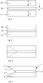
Fig.1 is a view from above of two die members in an ejection position, i.e. open position, -
Fig. 2 is a view corresponding tofig. 1 showing the die members in a pressing position, i.e. closed position, -
Fig. 3 is an end view according to II-II infig. 1 showing a first embodiment of a die member, -
Fig. 4 is an end view according to II-II infig. 1 showing a second embodiment of a die member, -
Fig. 5 is an enlarged view from above of a die member according to the present disclosure, and -
Figs. 6-9 shows steps of an embodiment of a method according to the present disclosure. -
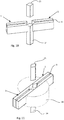
Fig. 10 shows a press tool according to the invention, and -
Fig. 11 shows a press tool according to the invention including a fixture. -
Figs. 1 ,10 and 11 show parts of a press tool according to the present disclosure. The press tool is a press tool for manufacturing a cutting insert green body, and in the embodiment shown it comprises twodie members die cavity 3. The press tool also comprises twopunches 24, 25 (visible infigs. 10 and 11 ) configured to be introduced from below and above into thedie cavity 3 for the purpose of compacting a powder introduced into said die cavity into a cutting insert green body. Infig. 11 , also afixture 26, in which thedie members - Only one of the
die members - The
die member 1 comprises a solid body that has afirst leg 4 defining afirst die surface 5 and asecond leg 6 defining asecond die surface 7. Thefirst die surface 5 and thesecond die surface 7 delimit adie cavity 3 in which a cutting insert body is formed upon compaction of a powder in saiddie cavity 3. Thefirst die surface 5 and thesecond die surface 7 extend with an angle α of not more than 96º in relation to each other in acorner 8 of a corner region of thedie member 1 where the first andsecond surfaces corner 8 in said corner region has a corner curvature corresponding to a radius of less than 1.65 mm. - The
first leg 4 has a wedge-shape and thesecond leg 6 has a wedge-shape, each one with a base connected to a remaining part of thedie member 1 and a respectivefree end corner 8 where the first andsecond surfaces - The
die member 1 consists of cemented carbide, and, in said corner region, there is aportion 9 of thedie member 1 in which the cemented carbide has higher toughness than has the cemented carbide of the die member further away from the corner region in a direction towards a respective oppositefree end first leg 4 and thesecond leg 6. The material having lower toughness, has a higher wear resistance than the material having a higher toughness. Thus, the first andsecond surfaces portion 9 having higher toughness is located. - The difference in toughness between said
portion 9 and other parts of the die member is because the composition of the cemented carbide or the microstructure thereof is different between saidportion 9 and other parts of thedie member 1. For example, saidportion 9 may have a higher binder content and/or a larger mean carbide particle size than other parts of thedie member 1. - The
tough portion 9 extends in a direction y from atip 23 of the corner towards the opposite free ends 10, 11 of thefirst leg 4 and thesecond leg 6. Theportion 9 extends at least 0.1 mm of the length of the first and second die surfaces 5, 7 in a direction y from atip 23 of thecorner 8 towards the free ends 10, 11 of thefirst leg 4 and thesecond leg 6. Saidportion 9 extends not more than half of the length of the first and second die surfaces 5, 7 in a direction y from atip 23 of thecorner 8 towards the free ends 10, 11 of thefirst leg 4 and thesecond leg 6. Thetough portion 9 has a thickness in a direction of a normal to the first and second die surfaces, of at least 0.1 mm, preferably at least 1 mm. - In the embodiment shown, the
tough portion 9 extends from thetip 23 of thecorner 8 to anopposite end 13 of thedie member 1, in a first direction x pointing away from said first and second legs towards said opposite end. The direction x is parallel to the longitudinal direction of thedie member 1. Thetough portion 9 may, however, have a considerably shorter length in said direction x than the length of the die member. - In the embodiment shown, the
tough portion 9 has the same cross-section along its whole length from the tip of the corner to saidopposite end 13 of thedie member 1. Such design is not obligatory, but it facilitates production of the die member and it also enables further stepwise machining of the v-shaped recess that defines the first andsecond legs tough portion 9 in the corner region. -
Fig. 3 shows an embodiment in which the cross-section, as viewed on a plane perpendicular to the longitudinal direction x, of the tough portion, is rectangular and thetough portion 9 extends all the way from afirst end 14 to asecond end 15 in a direction which, in this case, is perpendicular to the previously mentioned longitudinal direction x and a direction in which a punch is to be moved into the die cavity in connection to compression of a powder therein. Thetough portion 9 extends in the first direction all the way from thecorner 8 to theopposite end 13 of thedie member 1. -
Fig. 4 shows an alternative embodiment in which the tough portion 9' has a circular cross-section when viewed on a plane perpendicular to the longitudinal direction x. - The
tough portion 9, 9' is positioned in thecorner 8 in thedie cavity 3 where an cutting insert green body is finally compressed, i.e. the tough portion is positioned in a part of thedie cavity 3 where the stress, caused by the compaction pressure onto the first andsecond surfaces - The
first leg 4 has anouter surface 16 on an opposite side of thefirst leg 4 with regard to saidfirst surface 5, and thesecond leg 6 has anouter surface 17 on an opposite side of thesecond leg 6 with regard to saidsecond surface 7. Theouter surface 16 of thefirst leg 4 is parallel with theouter surface 17 of thesecond leg 6. - From the
first leg 4 towards anopposite end 13 of thedie member 1, in the extension of theouter surface 16 of thefirst leg 4 in said longitudinal direction x, the remaining part of thedie member 1 has anouter surface 18 which is in alignment with theouter surface 16 of thefirst leg 4. From thesecond leg 6 towards anopposite end 13 of thedie member 1, in the extension of theouter surface 17 of thesecond leg 6 in said longitudinal direction x, the remaining part of thedie member 1 has anouter surface 19 which is in alignment with theouter surface 17 of thesecond leg 6. This design makes it possible to machine a v-shaped recess in the end of a rectangular parallelepiped having such parallel outer surfaces as described above, and using the recess as a die cavity. When the inner surfaces such a recess become worn due to the wearing effect of powder being compressed repeatedly therein, the recess can simply be displaced further into the rectangular parallelepiped by way of suitable machining, while the crucial geometric measures of the part of thedie member 1 that defines the recess and, thereby, the die cavity remain the same. - In the disclosed embodiment the
die member 1 is formed by a rectangular parallelepiped having neighbouring outer surfaces that are perpendicular to each other, wherein said v-shaped recess is formed into one end of the rectangular parallelepiped.Figs. 4-6 show steps of a method of producing adie member 1 according the present disclosure. In a first step and a second step, not shown, a powder has been formed into two first green bodies that have been sintered and that are configured to form afirst part die member 1 when later joined together. In the embodiment shown, the twofirst parts fig. 6 are rectangular parallelepipeds, having the shapes of rectangular sheets with a respective thickness ti, t2. In this embodiment t1=t2. However, the first twoparts die member 1. - In corresponding first and second steps, a second powder, having a different microstructure and/or composition, than the powder forming the first green body, has been formed and sintered to form a
second part 22 of thedie member 1 when later joined together with thefirst part second part 22 has a thickness t3. Thesecond part 22 is aimed to form thetougher portion 9 disclosed hereinabove, and for that purpose, the thickness t3 thereof is, in this embodiment, substantially smaller than the thickness t1, t2 of thefirst parts - According to one embodiment the
first part second part 22 is made of cemented carbide having a cobalt content of 6 to 25 wt%. - According to one embodiment the
first part second part 22 is made of cemented carbide comprising tungsten carbide particles having an average grain size of 0.5 to 8.0 µm. - In a subsequent step, shown in
fig. 7 , thesecond part 22 is sandwiched between thefirst parts - A rectangular parallelepiped has thus been formed. In a further step, indicated in
fig. 8 , a v-shaped recess is machined into an end of the body formed by said first and second parts, such that adie member 1, indicated infig. 9 , having the shape disclosed hereinabove is obtained. - Instead of forming the
green bodies - Although the die surfaces 5, 7 are shown in the figures as planar surfaces and in cross sections as straight lines, it should be understood that the die surfaces may be non-planar corresponding to the green body geometry.
- It should be stated that, although in the disclosed embodiment the present invention has been exemplified as comprised by two
first bodies tough portion 9 is formed in the region of acorner 8 of the formeddie member 1 as indicated hereinabove and as further defined in the appended patent claims.
Claims (16)
- A press tool for manufacturing a cutting insert green body, said press tool comprising:- at least one die member (1) having a first leg (4) defining a first die surface (5) and a second leg (6) defining a second die surface (7), each leg (4, 6) having a base connected to a remaining part of the die member (1) and a respective free end (10, 11) at an end of the first and second die surfaces (5, 7),- wherein said first die surface (5) and second die surface (7) delimit a die cavity (3) in which said cutting insert green body is formed upon compaction of a powder in said die cavity (3),- wherein, in the region of the bases of said first and second legs (4, 6), the die cavity (3) presents a corner region with a corner (8) between two meeting surfaces, and- wherein said die member (1) consists of cemented carbide, and said press tool being characterised in that, in said corner region, there is a portion (9) of the die member (1) in which the cemented carbide has higher toughness than has the cemented carbide of the die member (1) further away from the corner region.
- A press tool according to claim 1, characterised in that at least one of said two meeting surfaces is one of said first and second die surface (5, 7).
- A press tool according to claim 1, characterised in that said two meeting surfaces are said first and second die surfaces (5, 7).
- A press tool according to any one of claims 1-3, characterised in that said portion (9) extends at least 0.1 mm measured along the first and second die surfaces (5, 7) in a direction (y) from a tip (23) of the corner (8) towards the free ends (10, 11) of the first leg (4) and the second leg (6).
- A press tool according to any one of claims 1-4, characterised in that said portion (9) extends not more than half of the length of the die surfaces (5, 7) measured along the first and second die surfaces (5, 7) in a direction (y) from a tip (23) of the corner (8) towards the free ends (10, 11) of the first leg (4) and the second leg (6).
- A press tool according to any one of claims 1-5, characterised in that said portion (9) has a thickness of at least 0.1 mm in a direction of a normal to the die surface (5, 7) of said portion (9) that delimits the die cavity (3).
- A press tool according to any one of claims 1-6, characterised in that said portion (9) extends from a tip (23) of said corner (8) to an opposite end (13) of the die member (1) in a first direction (x) pointing away from said first and second legs (4, 6) towards said opposite end (13).
- A press tool according to any one of claims 1-7, characterised in that, said portion (9) extends along said corner (8) from a first end (14) to an opposite second end (15) of said die member (1).
- A press tool according to any one of claims 1-8, characterised in that, viewed on a plane perpendicularly to a first direction (x) from a tip (23) of the corner towards an opposite end (13) of the die member (1), said portion (9) has a rectangular cross-section.
- A press tool according to any one of claims 1-7, characterised in that, viewed on a plane perpendicularly to a first direction (x) from the tip (23) of the corner towards an opposite end (13) of the die member (1), said portion (9) has an oval or circular cross-section.
- A press tool according to claim any one of claims 1-10, characterised in that, viewed on a plane perpendicularly to a first direction (x) from the tip (23) of the corner (8) towards an opposite end (13) of the die member (1), said portion (9) has the same cross-section along its whole length from the tip (23) of the corner (8) towards said opposite end (13) of the die member (1).
- A press tool according to any one of claims 1-11, characterised in that the first leg (4) has a wedge-shape and the second leg (6) has a wedge-shape, each one with a base connected to a remaining part of the die member (1) and a respective free end (10, 11) at an end of the first and second die surfaces (5, 7) opposite to said corner (8).
- A press tool according to any one of claims 1-12, characterised in that the cemented carbide forming said portion (9) has larger average carbide particle size than the cemented carbide forming the first leg (4) and the second leg (6).
- A press tool according to any one of claims 1-13, characterised in that the cemented carbide comprises particles of tungsten carbide in a matrix of a cobalt binder, and the cemented carbide forming said portion (9) has higher cobalt content than the cemented carbide forming the first leg (4) and the second leg (6).
- A press tool according to any one of claims 1-14, characterised in that it comprises first die member (1) according to any one of claims 1-14 and a corresponding second die member (2), which first and second die members (1, 2) are configured to be positioned with free ends (10, 11) of their respective first and second legs (4, 6) directed towards each other and thereby defining a die cavity (3), and at least one punch (24, 25) arranged to be introduced into the die cavity (3) defined by the first die member (1) and the second die member (1) for the purpose of compacting a powder introduced into said die cavity (3).
- A method of producing a press tool according to any one of claims 1-15, comprising the steps of:- forming a first green body configured to form a first part (20, 21) of a die member (1),- forming a second green body configured to form a second part (22) of a die member (1)- sintering the first green body into a first part (20, 21) of the die member (1),- sintering the second green body into a second part (22) of the die member (1), which second part will form said portion (9) of the die member (1) when attached to the first part (20, 21), and- attaching the first part (20, 21) to the second part (22) by means of sintering, wherein, in an interface between the first part and the second part, a binder in the first part and a binder in the second part are molten during said sintering.
Priority Applications (2)
| Application Number | Priority Date | Filing Date | Title |
|---|---|---|---|
| EP19157928.3A EP3698901B1 (en) | 2019-02-19 | 2019-02-19 | A press tool |
| JP2020021988A JP7478545B2 (en) | 2019-02-19 | 2020-02-13 | Press tool and method for manufacturing press tool |
Applications Claiming Priority (1)
| Application Number | Priority Date | Filing Date | Title |
|---|---|---|---|
| EP19157928.3A EP3698901B1 (en) | 2019-02-19 | 2019-02-19 | A press tool |
Publications (2)
| Publication Number | Publication Date |
|---|---|
| EP3698901A1 true EP3698901A1 (en) | 2020-08-26 |
| EP3698901B1 EP3698901B1 (en) | 2023-09-20 |
Family
ID=65493993
Family Applications (1)
| Application Number | Title | Priority Date | Filing Date |
|---|---|---|---|
| EP19157928.3A Active EP3698901B1 (en) | 2019-02-19 | 2019-02-19 | A press tool |
Country Status (2)
| Country | Link |
|---|---|
| EP (1) | EP3698901B1 (en) |
| JP (1) | JP7478545B2 (en) |
Citations (2)
| Publication number | Priority date | Publication date | Assignee | Title |
|---|---|---|---|---|
| US5543235A (en) * | 1994-04-26 | 1996-08-06 | Sintermet | Multiple grade cemented carbide articles and a method of making the same |
| WO2015120496A1 (en) * | 2014-02-17 | 2015-08-20 | Ceratizit Austria | Moulding tool, method for producing a green body, and use of the moulding tool |
Family Cites Families (5)
| Publication number | Priority date | Publication date | Assignee | Title |
|---|---|---|---|---|
| JPH09248633A (en) * | 1996-03-18 | 1997-09-22 | Hitachi Metals Ltd | Composite punch for punching fine holes and manufacturing method thereof |
| JP2003193168A (en) * | 2001-12-28 | 2003-07-09 | Honda Motor Co Ltd | Gradient composite material and manufacturing method thereof |
| JP5850495B2 (en) * | 2011-11-21 | 2016-02-03 | 国立研究開発法人産業技術総合研究所 | High hardness and toughness cermet |
| JP5152770B1 (en) * | 2012-02-20 | 2013-02-27 | 有限会社Mts | Method for producing tough cemented carbide |
| JP6331558B2 (en) * | 2014-03-26 | 2018-05-30 | 日立化成株式会社 | Die for powder molding |
-
2019
- 2019-02-19 EP EP19157928.3A patent/EP3698901B1/en active Active
-
2020
- 2020-02-13 JP JP2020021988A patent/JP7478545B2/en active Active
Patent Citations (2)
| Publication number | Priority date | Publication date | Assignee | Title |
|---|---|---|---|---|
| US5543235A (en) * | 1994-04-26 | 1996-08-06 | Sintermet | Multiple grade cemented carbide articles and a method of making the same |
| WO2015120496A1 (en) * | 2014-02-17 | 2015-08-20 | Ceratizit Austria | Moulding tool, method for producing a green body, and use of the moulding tool |
Also Published As
| Publication number | Publication date |
|---|---|
| EP3698901B1 (en) | 2023-09-20 |
| JP2020168660A (en) | 2020-10-15 |
| JP7478545B2 (en) | 2024-05-07 |
Similar Documents
| Publication | Publication Date | Title |
|---|---|---|
| EP1843892B1 (en) | Manufacturing cutting inserts | |
| CN103732386B (en) | Apparatus and method for manufacturing cutting inserts | |
| EP0211643B1 (en) | Powder metal consolidation of multiple preforms | |
| US20170282254A1 (en) | Method and arrangement for manufacturing a cutting insert | |
| CN1708371A (en) | Method and apparatus for cross-hole pressing to produce cutting inserts | |
| JP2019536642A (en) | Manufacturing method and manufacturing apparatus for cemented carbide pressed product and cemented carbide pressed product | |
| CN102076964B (en) | Die for forging rotor material and method for forging rotor material | |
| US11241737B2 (en) | Manufacturing a hard-metal pressed article | |
| US20170246687A1 (en) | Mould, method for producing a green compact and use of the mould | |
| US20160263665A1 (en) | Composite blanks and tooling for cutting applications | |
| CN110709193B (en) | Powder molding and pressing method and powder molding and pressing device for compacts for cutting inserts | |
| CN105149894B (en) | A kind of preparation method of micro- texture carbide chip | |
| EP2519378B1 (en) | Blank for the manufacture of a machining tool and method of use of a blank for the manufacture of a machining tool | |
| JP7236397B2 (en) | Cutting plate and method and compression mold for manufacturing cutting plate green body | |
| JP3215368B2 (en) | Method of manufacturing indexable tip and indexable tip | |
| EP3698901B1 (en) | A press tool | |
| JPH11156606A (en) | Indexable insert, indexable insert manufacturing method and tool unit | |
| CN110997190B (en) | Method for producing a sintered component and sintered component | |
| JP6380614B1 (en) | Powder forming press method and powder forming press apparatus for green compact for cutting insert | |
| JP6354893B1 (en) | Powder forming press method and powder forming press apparatus for green compact for cutting insert |
Legal Events
| Date | Code | Title | Description |
|---|---|---|---|
| PUAI | Public reference made under article 153(3) epc to a published international application that has entered the european phase |
Free format text: ORIGINAL CODE: 0009012 |
|
| STAA | Information on the status of an ep patent application or granted ep patent |
Free format text: STATUS: THE APPLICATION HAS BEEN PUBLISHED |
|
| AK | Designated contracting states |
Kind code of ref document: A1 Designated state(s): AL AT BE BG CH CY CZ DE DK EE ES FI FR GB GR HR HU IE IS IT LI LT LU LV MC MK MT NL NO PL PT RO RS SE SI SK SM TR |
|
| AX | Request for extension of the european patent |
Extension state: BA ME |
|
| STAA | Information on the status of an ep patent application or granted ep patent |
Free format text: STATUS: REQUEST FOR EXAMINATION WAS MADE |
|
| 17P | Request for examination filed |
Effective date: 20210226 |
|
| RBV | Designated contracting states (corrected) |
Designated state(s): AL AT BE BG CH CY CZ DE DK EE ES FI FR GB GR HR HU IE IS IT LI LT LU LV MC MK MT NL NO PL PT RO RS SE SI SK SM TR |
|
| GRAP | Despatch of communication of intention to grant a patent |
Free format text: ORIGINAL CODE: EPIDOSNIGR1 |
|
| STAA | Information on the status of an ep patent application or granted ep patent |
Free format text: STATUS: GRANT OF PATENT IS INTENDED |
|
| INTG | Intention to grant announced |
Effective date: 20230428 |
|
| GRAS | Grant fee paid |
Free format text: ORIGINAL CODE: EPIDOSNIGR3 |
|
| GRAA | (expected) grant |
Free format text: ORIGINAL CODE: 0009210 |
|
| STAA | Information on the status of an ep patent application or granted ep patent |
Free format text: STATUS: THE PATENT HAS BEEN GRANTED |
|
| AK | Designated contracting states |
Kind code of ref document: B1 Designated state(s): AL AT BE BG CH CY CZ DE DK EE ES FI FR GB GR HR HU IE IS IT LI LT LU LV MC MK MT NL NO PL PT RO RS SE SI SK SM TR |
|
| REG | Reference to a national code |
Ref country code: GB Ref legal event code: FG4D |
|
| REG | Reference to a national code |
Ref country code: CH Ref legal event code: EP |
|
| REG | Reference to a national code |
Ref country code: IE Ref legal event code: FG4D |
|
| REG | Reference to a national code |
Ref country code: DE Ref legal event code: R096 Ref document number: 602019037689 Country of ref document: DE |
|
| P01 | Opt-out of the competence of the unified patent court (upc) registered |
Effective date: 20231115 |
|
| REG | Reference to a national code |
Ref country code: LT Ref legal event code: MG9D |
|
| PG25 | Lapsed in a contracting state [announced via postgrant information from national office to epo] |
Ref country code: GR Free format text: LAPSE BECAUSE OF FAILURE TO SUBMIT A TRANSLATION OF THE DESCRIPTION OR TO PAY THE FEE WITHIN THE PRESCRIBED TIME-LIMIT Effective date: 20231221 |
|
| REG | Reference to a national code |
Ref country code: NL Ref legal event code: MP Effective date: 20230920 |
|
| PG25 | Lapsed in a contracting state [announced via postgrant information from national office to epo] |
Ref country code: SE Free format text: LAPSE BECAUSE OF FAILURE TO SUBMIT A TRANSLATION OF THE DESCRIPTION OR TO PAY THE FEE WITHIN THE PRESCRIBED TIME-LIMIT Effective date: 20230920 Ref country code: RS Free format text: LAPSE BECAUSE OF FAILURE TO SUBMIT A TRANSLATION OF THE DESCRIPTION OR TO PAY THE FEE WITHIN THE PRESCRIBED TIME-LIMIT Effective date: 20230920 Ref country code: NO Free format text: LAPSE BECAUSE OF FAILURE TO SUBMIT A TRANSLATION OF THE DESCRIPTION OR TO PAY THE FEE WITHIN THE PRESCRIBED TIME-LIMIT Effective date: 20231220 Ref country code: LV Free format text: LAPSE BECAUSE OF FAILURE TO SUBMIT A TRANSLATION OF THE DESCRIPTION OR TO PAY THE FEE WITHIN THE PRESCRIBED TIME-LIMIT Effective date: 20230920 Ref country code: LT Free format text: LAPSE BECAUSE OF FAILURE TO SUBMIT A TRANSLATION OF THE DESCRIPTION OR TO PAY THE FEE WITHIN THE PRESCRIBED TIME-LIMIT Effective date: 20230920 Ref country code: HR Free format text: LAPSE BECAUSE OF FAILURE TO SUBMIT A TRANSLATION OF THE DESCRIPTION OR TO PAY THE FEE WITHIN THE PRESCRIBED TIME-LIMIT Effective date: 20230920 Ref country code: GR Free format text: LAPSE BECAUSE OF FAILURE TO SUBMIT A TRANSLATION OF THE DESCRIPTION OR TO PAY THE FEE WITHIN THE PRESCRIBED TIME-LIMIT Effective date: 20231221 Ref country code: FI Free format text: LAPSE BECAUSE OF FAILURE TO SUBMIT A TRANSLATION OF THE DESCRIPTION OR TO PAY THE FEE WITHIN THE PRESCRIBED TIME-LIMIT Effective date: 20230920 |
|
| REG | Reference to a national code |
Ref country code: AT Ref legal event code: MK05 Ref document number: 1613034 Country of ref document: AT Kind code of ref document: T Effective date: 20230920 |
|
| PG25 | Lapsed in a contracting state [announced via postgrant information from national office to epo] |
Ref country code: NL Free format text: LAPSE BECAUSE OF FAILURE TO SUBMIT A TRANSLATION OF THE DESCRIPTION OR TO PAY THE FEE WITHIN THE PRESCRIBED TIME-LIMIT Effective date: 20230920 |
|
| PG25 | Lapsed in a contracting state [announced via postgrant information from national office to epo] |
Ref country code: IS Free format text: LAPSE BECAUSE OF FAILURE TO SUBMIT A TRANSLATION OF THE DESCRIPTION OR TO PAY THE FEE WITHIN THE PRESCRIBED TIME-LIMIT Effective date: 20240120 |
|
| PG25 | Lapsed in a contracting state [announced via postgrant information from national office to epo] |
Ref country code: AT Free format text: LAPSE BECAUSE OF FAILURE TO SUBMIT A TRANSLATION OF THE DESCRIPTION OR TO PAY THE FEE WITHIN THE PRESCRIBED TIME-LIMIT Effective date: 20230920 |
|
| PG25 | Lapsed in a contracting state [announced via postgrant information from national office to epo] |
Ref country code: ES Free format text: LAPSE BECAUSE OF FAILURE TO SUBMIT A TRANSLATION OF THE DESCRIPTION OR TO PAY THE FEE WITHIN THE PRESCRIBED TIME-LIMIT Effective date: 20230920 |
|
| PG25 | Lapsed in a contracting state [announced via postgrant information from national office to epo] |
Ref country code: SM Free format text: LAPSE BECAUSE OF FAILURE TO SUBMIT A TRANSLATION OF THE DESCRIPTION OR TO PAY THE FEE WITHIN THE PRESCRIBED TIME-LIMIT Effective date: 20230920 Ref country code: RO Free format text: LAPSE BECAUSE OF FAILURE TO SUBMIT A TRANSLATION OF THE DESCRIPTION OR TO PAY THE FEE WITHIN THE PRESCRIBED TIME-LIMIT Effective date: 20230920 Ref country code: IS Free format text: LAPSE BECAUSE OF FAILURE TO SUBMIT A TRANSLATION OF THE DESCRIPTION OR TO PAY THE FEE WITHIN THE PRESCRIBED TIME-LIMIT Effective date: 20240120 Ref country code: ES Free format text: LAPSE BECAUSE OF FAILURE TO SUBMIT A TRANSLATION OF THE DESCRIPTION OR TO PAY THE FEE WITHIN THE PRESCRIBED TIME-LIMIT Effective date: 20230920 Ref country code: EE Free format text: LAPSE BECAUSE OF FAILURE TO SUBMIT A TRANSLATION OF THE DESCRIPTION OR TO PAY THE FEE WITHIN THE PRESCRIBED TIME-LIMIT Effective date: 20230920 Ref country code: CZ Free format text: LAPSE BECAUSE OF FAILURE TO SUBMIT A TRANSLATION OF THE DESCRIPTION OR TO PAY THE FEE WITHIN THE PRESCRIBED TIME-LIMIT Effective date: 20230920 Ref country code: AT Free format text: LAPSE BECAUSE OF FAILURE TO SUBMIT A TRANSLATION OF THE DESCRIPTION OR TO PAY THE FEE WITHIN THE PRESCRIBED TIME-LIMIT Effective date: 20230920 Ref country code: SK Free format text: LAPSE BECAUSE OF FAILURE TO SUBMIT A TRANSLATION OF THE DESCRIPTION OR TO PAY THE FEE WITHIN THE PRESCRIBED TIME-LIMIT Effective date: 20230920 Ref country code: PT Free format text: LAPSE BECAUSE OF FAILURE TO SUBMIT A TRANSLATION OF THE DESCRIPTION OR TO PAY THE FEE WITHIN THE PRESCRIBED TIME-LIMIT Effective date: 20240122 |
|
| PG25 | Lapsed in a contracting state [announced via postgrant information from national office to epo] |
Ref country code: PL Free format text: LAPSE BECAUSE OF FAILURE TO SUBMIT A TRANSLATION OF THE DESCRIPTION OR TO PAY THE FEE WITHIN THE PRESCRIBED TIME-LIMIT Effective date: 20230920 |
|
| REG | Reference to a national code |
Ref country code: DE Ref legal event code: R097 Ref document number: 602019037689 Country of ref document: DE |
|
| PG25 | Lapsed in a contracting state [announced via postgrant information from national office to epo] |
Ref country code: DK Free format text: LAPSE BECAUSE OF FAILURE TO SUBMIT A TRANSLATION OF THE DESCRIPTION OR TO PAY THE FEE WITHIN THE PRESCRIBED TIME-LIMIT Effective date: 20230920 |
|
| PLBE | No opposition filed within time limit |
Free format text: ORIGINAL CODE: 0009261 |
|
| STAA | Information on the status of an ep patent application or granted ep patent |
Free format text: STATUS: NO OPPOSITION FILED WITHIN TIME LIMIT |
|
| PG25 | Lapsed in a contracting state [announced via postgrant information from national office to epo] |
Ref country code: DK Free format text: LAPSE BECAUSE OF FAILURE TO SUBMIT A TRANSLATION OF THE DESCRIPTION OR TO PAY THE FEE WITHIN THE PRESCRIBED TIME-LIMIT Effective date: 20230920 |
|
| 26N | No opposition filed |
Effective date: 20240621 |
|
| PG25 | Lapsed in a contracting state [announced via postgrant information from national office to epo] |
Ref country code: MC Free format text: LAPSE BECAUSE OF FAILURE TO SUBMIT A TRANSLATION OF THE DESCRIPTION OR TO PAY THE FEE WITHIN THE PRESCRIBED TIME-LIMIT Effective date: 20230920 |
|
| REG | Reference to a national code |
Ref country code: CH Ref legal event code: PL |
|
| PG25 | Lapsed in a contracting state [announced via postgrant information from national office to epo] |
Ref country code: LU Free format text: LAPSE BECAUSE OF NON-PAYMENT OF DUE FEES Effective date: 20240219 |
|
| PG25 | Lapsed in a contracting state [announced via postgrant information from national office to epo] |
Ref country code: CH Free format text: LAPSE BECAUSE OF NON-PAYMENT OF DUE FEES Effective date: 20240229 |
|
| PG25 | Lapsed in a contracting state [announced via postgrant information from national office to epo] |
Ref country code: SI Free format text: LAPSE BECAUSE OF FAILURE TO SUBMIT A TRANSLATION OF THE DESCRIPTION OR TO PAY THE FEE WITHIN THE PRESCRIBED TIME-LIMIT Effective date: 20230920 |
|
| PG25 | Lapsed in a contracting state [announced via postgrant information from national office to epo] |
Ref country code: SI Free format text: LAPSE BECAUSE OF FAILURE TO SUBMIT A TRANSLATION OF THE DESCRIPTION OR TO PAY THE FEE WITHIN THE PRESCRIBED TIME-LIMIT Effective date: 20230920 Ref country code: LU Free format text: LAPSE BECAUSE OF NON-PAYMENT OF DUE FEES Effective date: 20240219 Ref country code: CH Free format text: LAPSE BECAUSE OF NON-PAYMENT OF DUE FEES Effective date: 20240229 |
|
| PG25 | Lapsed in a contracting state [announced via postgrant information from national office to epo] |
Ref country code: BG Free format text: LAPSE BECAUSE OF FAILURE TO SUBMIT A TRANSLATION OF THE DESCRIPTION OR TO PAY THE FEE WITHIN THE PRESCRIBED TIME-LIMIT Effective date: 20230920 |
|
| PG25 | Lapsed in a contracting state [announced via postgrant information from national office to epo] |
Ref country code: BG Free format text: LAPSE BECAUSE OF FAILURE TO SUBMIT A TRANSLATION OF THE DESCRIPTION OR TO PAY THE FEE WITHIN THE PRESCRIBED TIME-LIMIT Effective date: 20230920 |
|
| REG | Reference to a national code |
Ref country code: BE Ref legal event code: MM Effective date: 20240229 |
|
| PG25 | Lapsed in a contracting state [announced via postgrant information from national office to epo] |
Ref country code: BE Free format text: LAPSE BECAUSE OF NON-PAYMENT OF DUE FEES Effective date: 20240229 |
|
| PG25 | Lapsed in a contracting state [announced via postgrant information from national office to epo] |
Ref country code: IE Free format text: LAPSE BECAUSE OF NON-PAYMENT OF DUE FEES Effective date: 20240219 |
|
| PG25 | Lapsed in a contracting state [announced via postgrant information from national office to epo] |
Ref country code: IE Free format text: LAPSE BECAUSE OF NON-PAYMENT OF DUE FEES Effective date: 20240219 Ref country code: BE Free format text: LAPSE BECAUSE OF NON-PAYMENT OF DUE FEES Effective date: 20240229 |
|
| PG25 | Lapsed in a contracting state [announced via postgrant information from national office to epo] |
Ref country code: CY Free format text: LAPSE BECAUSE OF FAILURE TO SUBMIT A TRANSLATION OF THE DESCRIPTION OR TO PAY THE FEE WITHIN THE PRESCRIBED TIME-LIMIT; INVALID AB INITIO Effective date: 20190219 |
|
| PG25 | Lapsed in a contracting state [announced via postgrant information from national office to epo] |
Ref country code: HU Free format text: LAPSE BECAUSE OF FAILURE TO SUBMIT A TRANSLATION OF THE DESCRIPTION OR TO PAY THE FEE WITHIN THE PRESCRIBED TIME-LIMIT; INVALID AB INITIO Effective date: 20190219 |
|
| PG25 | Lapsed in a contracting state [announced via postgrant information from national office to epo] |
Ref country code: TR Free format text: LAPSE BECAUSE OF FAILURE TO SUBMIT A TRANSLATION OF THE DESCRIPTION OR TO PAY THE FEE WITHIN THE PRESCRIBED TIME-LIMIT Effective date: 20230920 |
|
| PGFP | Annual fee paid to national office [announced via postgrant information from national office to epo] |
Ref country code: GB Payment date: 20260106 Year of fee payment: 8 |
|
| PGFP | Annual fee paid to national office [announced via postgrant information from national office to epo] |
Ref country code: DE Payment date: 20251230 Year of fee payment: 8 |
|
| PGFP | Annual fee paid to national office [announced via postgrant information from national office to epo] |
Ref country code: IT Payment date: 20260122 Year of fee payment: 8 |
|
| PGFP | Annual fee paid to national office [announced via postgrant information from national office to epo] |
Ref country code: FR Payment date: 20260121 Year of fee payment: 8 |