EP3698860A1 - Circular ring type drying machine - Google Patents
Circular ring type drying machine Download PDFInfo
- Publication number
- EP3698860A1 EP3698860A1 EP18868926.9A EP18868926A EP3698860A1 EP 3698860 A1 EP3698860 A1 EP 3698860A1 EP 18868926 A EP18868926 A EP 18868926A EP 3698860 A1 EP3698860 A1 EP 3698860A1
- Authority
- EP
- European Patent Office
- Prior art keywords
- extrusion
- cylinder
- circumferential surface
- feeding system
- annular groove
- Prior art date
- Legal status (The legal status is an assumption and is not a legal conclusion. Google has not performed a legal analysis and makes no representation as to the accuracy of the status listed.)
- Withdrawn
Links
Images




Classifications
-
- B—PERFORMING OPERATIONS; TRANSPORTING
- B29—WORKING OF PLASTICS; WORKING OF SUBSTANCES IN A PLASTIC STATE IN GENERAL
- B29B—PREPARATION OR PRETREATMENT OF THE MATERIAL TO BE SHAPED; MAKING GRANULES OR PREFORMS; RECOVERY OF PLASTICS OR OTHER CONSTITUENTS OF WASTE MATERIAL CONTAINING PLASTICS
- B29B13/00—Conditioning or physical treatment of the material to be shaped
- B29B13/06—Conditioning or physical treatment of the material to be shaped by drying
- B29B13/065—Conditioning or physical treatment of the material to be shaped by drying of powder or pellets
-
- B—PERFORMING OPERATIONS; TRANSPORTING
- B29—WORKING OF PLASTICS; WORKING OF SUBSTANCES IN A PLASTIC STATE IN GENERAL
- B29B—PREPARATION OR PRETREATMENT OF THE MATERIAL TO BE SHAPED; MAKING GRANULES OR PREFORMS; RECOVERY OF PLASTICS OR OTHER CONSTITUENTS OF WASTE MATERIAL CONTAINING PLASTICS
- B29B13/00—Conditioning or physical treatment of the material to be shaped
- B29B13/06—Conditioning or physical treatment of the material to be shaped by drying
-
- F—MECHANICAL ENGINEERING; LIGHTING; HEATING; WEAPONS; BLASTING
- F26—DRYING
- F26B—DRYING SOLID MATERIALS OR OBJECTS BY REMOVING LIQUID THEREFROM
- F26B9/00—Machines or apparatus for drying solid materials or objects at rest or with only local agitation; Domestic airing cupboards
- F26B9/06—Machines or apparatus for drying solid materials or objects at rest or with only local agitation; Domestic airing cupboards in stationary drums or chambers
- F26B9/063—Machines or apparatus for drying solid materials or objects at rest or with only local agitation; Domestic airing cupboards in stationary drums or chambers for drying granular material in bulk, e.g. grain bins or silos with false floor
-
- B—PERFORMING OPERATIONS; TRANSPORTING
- B01—PHYSICAL OR CHEMICAL PROCESSES OR APPARATUS IN GENERAL
- B01D—SEPARATION
- B01D1/00—Evaporating
- B01D1/22—Evaporating by bringing a thin layer of the liquid into contact with a heated surface
- B01D1/24—Evaporating by bringing a thin layer of the liquid into contact with a heated surface to obtain dry solids
-
- B—PERFORMING OPERATIONS; TRANSPORTING
- B01—PHYSICAL OR CHEMICAL PROCESSES OR APPARATUS IN GENERAL
- B01D—SEPARATION
- B01D1/00—Evaporating
- B01D1/30—Accessories for evaporators ; Constructional details thereof
-
- B—PERFORMING OPERATIONS; TRANSPORTING
- B29—WORKING OF PLASTICS; WORKING OF SUBSTANCES IN A PLASTIC STATE IN GENERAL
- B29B—PREPARATION OR PRETREATMENT OF THE MATERIAL TO BE SHAPED; MAKING GRANULES OR PREFORMS; RECOVERY OF PLASTICS OR OTHER CONSTITUENTS OF WASTE MATERIAL CONTAINING PLASTICS
- B29B13/00—Conditioning or physical treatment of the material to be shaped
- B29B13/02—Conditioning or physical treatment of the material to be shaped by heating
-
- F—MECHANICAL ENGINEERING; LIGHTING; HEATING; WEAPONS; BLASTING
- F26—DRYING
- F26B—DRYING SOLID MATERIALS OR OBJECTS BY REMOVING LIQUID THEREFROM
- F26B23/00—Heating arrangements
- F26B23/10—Heating arrangements using tubes or passages containing heated fluids, e.g. acting as radiative elements; Closed-loop systems
-
- F—MECHANICAL ENGINEERING; LIGHTING; HEATING; WEAPONS; BLASTING
- F26—DRYING
- F26B—DRYING SOLID MATERIALS OR OBJECTS BY REMOVING LIQUID THEREFROM
- F26B25/00—Details of general application not covered by group F26B21/00 or F26B23/00
- F26B25/001—Handling, e.g. loading or unloading arrangements
- F26B25/002—Handling, e.g. loading or unloading arrangements for bulk goods
-
- F—MECHANICAL ENGINEERING; LIGHTING; HEATING; WEAPONS; BLASTING
- F26—DRYING
- F26B—DRYING SOLID MATERIALS OR OBJECTS BY REMOVING LIQUID THEREFROM
- F26B25/00—Details of general application not covered by group F26B21/00 or F26B23/00
- F26B25/04—Agitating, stirring, or scraping devices
-
- F—MECHANICAL ENGINEERING; LIGHTING; HEATING; WEAPONS; BLASTING
- F26—DRYING
- F26B—DRYING SOLID MATERIALS OR OBJECTS BY REMOVING LIQUID THEREFROM
- F26B25/00—Details of general application not covered by group F26B21/00 or F26B23/00
- F26B25/06—Chambers, containers, or receptacles
- F26B25/08—Parts thereof
-
- F—MECHANICAL ENGINEERING; LIGHTING; HEATING; WEAPONS; BLASTING
- F26—DRYING
- F26B—DRYING SOLID MATERIALS OR OBJECTS BY REMOVING LIQUID THEREFROM
- F26B3/00—Drying solid materials or objects by processes involving the application of heat
- F26B3/18—Drying solid materials or objects by processes involving the application of heat by conduction, i.e. the heat is conveyed from the heat source, e.g. gas flame, to the materials or objects to be dried by direct contact
- F26B3/20—Drying solid materials or objects by processes involving the application of heat by conduction, i.e. the heat is conveyed from the heat source, e.g. gas flame, to the materials or objects to be dried by direct contact the heat source being a heated surface, e.g. a moving belt or conveyor
-
- F—MECHANICAL ENGINEERING; LIGHTING; HEATING; WEAPONS; BLASTING
- F26—DRYING
- F26B—DRYING SOLID MATERIALS OR OBJECTS BY REMOVING LIQUID THEREFROM
- F26B9/00—Machines or apparatus for drying solid materials or objects at rest or with only local agitation; Domestic airing cupboards
- F26B9/06—Machines or apparatus for drying solid materials or objects at rest or with only local agitation; Domestic airing cupboards in stationary drums or chambers
Definitions
- the present invention relates to the technical field of drying of slurry materials, and in particular to a ring dryer.
- Heat exchange components of a hollow paddle dryer include a hollow paddle and a housing with a heating jacket. Due to the full contact with a slurry material, the heat exchange components have high surface utilization and high heat conduction efficiency. However, because the material is continuously stirred and turned by the paddle, there are problems such as wear of the paddle and large power consumption.
- An object of the present invention is to solve the deficiencies of the prior art and provide a ring dryer.
- a ring dryer comprising a housing, a top cover provided at the top of the housing, and a base provided at the bottom of the housing, and further comprising a feeding system into which the material to be dried flows, a material coating assembly, a material extrusion assembly, a discharging scraper, and at least two cylinders with different radii, wherein each of the cylinders is provided with a heat medium flow path inside, an annular groove is formed between the adjacent cylinders, and a material outlet is provided at a free end of the feeding system; the material to be dried in the feeding system flows into the annular groove along the material outlet; the material coating assembly, the material extrusion assembly and the discharging scraper are movably arranged in the annular groove and can move along the annular groove relative to the cylinders; and a blade of the discharging scraper is respectively in contact with an inner circumferential surface of the cylinder and an outer circumferential surface of the adjacent cylinder.
- the material extrusion assembly comprises an outer extrusion belt, an inner extrusion belt, an outer extrusion circular roll and an inner extrusion circular roll, wherein the outer extrusion circular roll drives the outer extrusion belt to rotate and move along the annular groove, and the outer extrusion belt is in contact with the inner circumferential surface of the cylinder; and the inner extrusion circular roll drives the inner extrusion belt to rotate and move along the annular groove, and the inner extrusion belt is in contact with the outer circumferential surface of the adjacent cylinder.
- the outer extrusion belt and the inner extrusion belt are arranged parallel to each other, and a separation circular roll is provided between the outer extrusion belt and the inner extrusion belt.
- the material coating assembly comprises a pair of material spreading circular rolls and a pair of material spreading plates, the pair of material spreading circular rolls being longitudinally arranged in the annular groove and parallel to an axis of the housing, wherein one end of one material spreading plate is close to one material spreading circular roll, and the other end thereof forms a distributing port together with the inner circumferential surface of the cylinder; and one end of the other material spreading plate is close to the other material spreading circular roll, and the other end thereof forms a distributing port together with the outer circumferential surface of the adjacent cylinder.
- the material coating assembly further comprises a material distributor, wherein the material distributor comprises several uniform distribution pipes in parallel, the material outlet of the feeding system is connected in a butt joint with a feeding port of the uniform distribution pipe on the inner side, and the uniform distribution pipe on the outer side is provided with several dispatching ports in sequence from top to bottom.
- an annular plate is provided at the top of the cylinder, toothing holes are uniformly distributed around the annular plate, a first gear is provided at the top of the outer extrusion circular roll, a second gear is provided at the top of the inner extrusion circular roll, the first gear rotates along the toothing holes of the annular plate, and the second gear rotates along the toothing holes of the adjacent annular plate.
- the feeding system is transversely arranged in the housing and can rotate around the axis of the housing, the free end of the feeding system is connected to an upper connecting plate, the top of the discharging scraper is connected to the upper connecting plate, the top of the material coating assembly is connected to the upper connecting plate, the top of the material extrusion assembly is connected to the upper connecting plate, the bottom of the discharging scraper is connected to a lower connecting plate, the bottom of the material coating assembly is connected to the lower connecting plate, and the bottom of the material extrusion assembly is connected to the lower connecting plate.
- the ring dryer further comprises a rotating shaft, wherein an annular rake rod is provided inside the base, and the rake rod is fixedly connected to the feeding system by means of the rotating shaft.
- the bottom of the housing is provided with a heat medium inlet pipe and a heat medium outlet pipe, wherein the heat medium inlet pipe is connected to an inlet of the heat medium flow channel of the cylinder, and the heat medium outlet pipe is connected to an outlet of the heat medium flow channel of the cylinder.
- the top cover is provided with a gas discharge port and a material inlet, and the material inlet is connected to the feeding port of the feeding system.
- the present invention has the beneficial effects in that the material to be dried is uniformly coated on the inner circumferential surface and the outer circumferential surface of the cylinders, thereby increasing the drying area of the material to be dried to ensure the material to be dried to receive heat continuously and steadily; and the material to be dried does not need to be vigorously stirred by the components of the present invention so as to reduce the friction between the material to be dried and the components, thereby extending the service life while reducing the power consumption.
- top cover 10 gas discharge port 11, material inlet 12, housing 20, cylinder 21, heat medium inlet pipe 210, heat medium outlet pipe 211, heat medium flow channel 212, annular groove 22, annular plate 23, toothing hole 24, first gear 25, second gear 26, upper connecting plate 27, lower connecting plate 28, hole 29, base 30, rake rod 31, rotating shaft 32, electric motor 33, rake blade 34, shaft holder 35, discharge port 36, feeding system 40, cross rod 41, feeding pipe 42, material outlet 43, material coating assembly 50, distributing circular roll 51, distributing plate 52, material distributor 53, uniform distribution pipe 531, dispatching port 532, distributing port 54, material extrusion assembly 60, outer extrusion belt 61, inner extrusion belt 62, outer extrusion circular roll 63, inner extrusion circular roll 64, separation circular roll 65, upper roller group 66, lower roller group 67, and discharging scraper 70.
- a ring dryer used for drying a slurry material comprises a housing 20, a top cover 10 provided at the top of the housing 20, and a base 30 provided at the bottom of the housing 20, and further comprises a feeding system 40 into which the material to be dried flows, a material coating assembly 50, a material extrusion assembly 60, a discharging scraper 70, and at least two cylinders 21 with different radii.
- the cylinder 21 is of a cylindrical structure, and a heat medium flow channel 212 is provided inside the cylinder 21.
- the cylinder 21 is a cylinder having a ring-shaped cavity provided inside, the ring-shaped cavity forms the heat medium flow channel 212, or a baffle plate is arranged in the ring-shaped cavity to form the heat medium flow channel 212.
- the cylinder 21 is fixedly arranged in the housing 20, an annular groove 22 is formed between the adjacent cylinders 21, and the cylinder 21 and the housing 20 are coaxially arranged.
- the feeding system 40 is transversely arranged in the housing 20 and can rotate around an axis of the housing 20.
- the feeding system 40 is composed of a cross rod 41 and a feeding pipe 42 or composed of a cross rod 41 and a feeding disc.
- a pipe wall of the feeding pipe 42 is provided with a material outlet 43, or the bottom of the feeding disc is provided with a material outlet 43, and the number of the material outlet 43 is equal to the number of the annular groove 22.
- the number of the cross rod 41 and of the feeding pipe 42 is equal to the number of the annular groove 22.
- Each feeding pipe 42 is provided with a material outlet 43, and the material to be dried in the feeding system 40 flows into the annular groove 22 along the material outlet 43.
- the material coating assembly 50, the material extrusion assembly 60 and the discharging scraper 70 are movably arranged in the annular groove 22 and can move along the annular groove 22 relative to the cylinder 21, and a blade of the discharging scraper 70 is respectively in contact with an inner circumferential surface of the cylinder 21 and an outer circumferential surface of the adjacent cylinder 21.
- the feeding system 40 is transversely arranged in the housing 20 and can rotate around the axis of the housing 20, the free end of the feeding system 40 is connected to an upper connecting plate 27, the top of the discharging scraper 70 is connected to the upper connecting plate 27, the top of the material coating assembly 50 is connected to the upper connecting plate 27, the top of the material extrusion assembly 60 is connected to the upper connecting plate 27, the bottom of the discharging scraper 70 is connected to a lower connecting plate 28, the bottom of the material coating assembly 50 is connected to the lower connecting plate 28, and the bottom of the material extrusion assembly 60 is connected to the lower connecting plate 28.
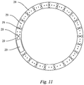
- the upper connecting plate 27 is of a ring shape and is provided with a hole 29 for passage of the material outlet 43, the upper connecting plate 27 is provided with holes 29 for connecting with the top of the discharging scraper 70, the top of the material coating assembly 50 and the top of the material extrusion assembly 60; and the lower connecting plate 28 is provided with holes 29 through which the dried material passes and enter the base 30, the lower connecting plate 28 is of a ring shape and is provided with holes 29 for connecting with the bottom of the discharging scraper 70, the bottom of the material coating assembly 50 and the bottom of the material extrusion assembly 60.
- the feeding system 40 and the upper connecting plate 27 can be detachably connected, can be connected by a pneumatic cylinder, or can be connected by an elastic member, such as connected by a spring.
- the feeding system 40 when the feeding system 40 is connected to the upper connecting plate 27 by a spring, when the feeding system 40 is suddenly turned, the spring provides a buffer action on the activation of the upper connecting plate 27, thereby protecting the discharging scraper 70, the material coating assembly 50 and the material extrusion assembly 60 connected to the upper connecting plate 27.
- the discharging scraper 70 is connected to the upper connecting plate 27 and the lower connecting plate 28, the blades of the discharging scraper 70 are respectively in contact with the inner circumferential surface of the cylinder 21 and the outer circumferential surface of the adjacent cylinder 21, and the dried material on the inner circumferential surface of the cylinder 21 and on the outer circumferential surface of the adjacent cylinder 21 can be scraped off by the discharging scraper 70.
- the material to be dried in the feeding system 40 flows to the annular groove 22 along the material outlet 43, and under the action of an external force, the feeding system 40, the material coating assembly 50, the material extrusion assembly 60 and the discharging scraper 70 move along the annular groove 22 relative to the cylinder 21, and the material to be dried is coated on the inner circumferential surface of the cylinder 21 and the outer circumferential surface of the adjacent cylinder 21 by the material coating assembly 50.
- the heat medium is introduced into the heat medium flow channel 212, and the materials to be dried on the inner circumferential surface of the cylinder 21 and the outer circumferential surface of the adjacent cylinder 21 is dried by the heat medium, and at the same time, the dried material is scraped off by the discharging scraper 70.
- the discharging scraper 70 is of a V-shaped structure, and during the movement of the discharging scraper 70 along the annular groove 22, the dried material on the inner circumferential surface of the cylinder 21 and on the outer circumferential surface of the adjacent cylinder 21 is simultaneously scraped off by the discharging scraper 70. Because both the inner circumferential surface of the cylinder 21 and the outer circumferential surface of the adjacent cylinder 21 are coated with the material to be dried, the area of the material to be dried is increased, thereby improving the drying efficiency; and at the same time, during the drying, the material to be dried has less friction with the components in the present invention, thereby extending the service life of the present invention.
- the material extrusion assembly 60 comprises an outer extrusion belt 61, an inner extrusion belt 62, an outer extrusion circular roll 63 and an inner extrusion circular roll 64.
- the outer extrusion circular roll 63 drives the outer extrusion belt 61 to rotate and move along the annular groove 22, and the outer extrusion belt 61 is in contact with the inner circumferential surface of the cylinder 21, so that the outer extrusion belt 61 tightly presses the material to be dried onto the inner circumferential surface of the cylinder 21; and the inner extrusion circular roll 64 drives the inner extrusion belt 62 to rotate and move along the annular groove 22, and the inner extrusion belt 62 is in contact with the outer circumferential surface of the adjacent cylinder 21, so that the inner extrusion belt 62 tightly presses the material to be dried onto the outer circumferential surface of the adjacent cylinder 21.
- Both the outer extrusion belt 61 and the inner extrusion belt 62 are made of a flexible and breathable material, which can be one or any combination of porous rubber, porous soft plastic, a porous metal sheet, a metal net, a non-metal net, metal cloth, non-metal cloth, foamed plastic, a chain plate, a bamboo mat and a straw mat.
- the outer extrusion belt 61 and the inner extrusion belt 62 are respectively parallel to the circumferential walls of the cylinders 21, and a separation circular roll 65 is provided between the outer extrusion belt 61 and the inner extrusion belt 62.
- the separation circular roll 65 is provided between the outer extrusion belt 61 and the inner extrusion belt 62, and the outer extrusion belt 61 and the inner extrusion belt 62 form a double-track structure.
- the inner extrusion belt 62 makes the material to be dried close to the outer circumferential surface of the adjacent cylinder 21 and prevents the material to be dried on the outer circumferential surface of the adjacent cylinder 21 from falling off.
- the material coating assembly 50 comprises a pair of distributing circular rolls 51 and a pair of distributing plates 52, the pair of distributing circular rolls 51 being longitudinally arranged in the annular groove 22 and parallel to the housing 20, wherein one end of one distributing plate 52 is close to one distributing circular roll 51, and the other end thereof forms a distributing port 54 together with the inner circumferential surface of the cylinder 21; and one end of the other distributing plate 52 is close to the other distributing circular roll 51, and the other end thereof forms a distributing port 54 together with the outer circumferential surface of the adjacent cylinder 21.
- the included angle between the distributing plate 52 and the inner circumferential surface of the cylinder 21 or the outer circumferential surface of the adjacent cylinder 21 can be adjusted as required to further adjust the size of the distributing port 54.
- the distributing circular roll 51 rotates and moves along the annular groove 22, the distributing circular roll 51 extrudes the material to be dried so that the material to be dried is in the shape of a uniform sheet, and the extruded material to be dried enters from the distributing port 54 and is attached to the inner circumferential surface of the cylinder 21 or the outer circumferential surface of the adjacent cylinder 21.
- annular plate 23 is provided at the top of each cylinder 21, and toothing holes 24 are uniformly distributed around the annular plate 23, a first gear 25 is provided at the top of the outer extrusion circular roll 63, a second gear 26 is provided at the top of the inner extrusion circular roll 64, the first gear 25 rotates along the toothing holes 24 of the annular plate 23, and the second gear 26 rotates along the toothing holes 24 of the annular plate 23.
- An upper roller group 66 is provided at the top of the outer extrusion circular roll 63 and the top of the inner extrusion circular roll 64, and the top of the outer extrusion circular roll 63 is connected to the top of the inner extrusion circular roll 64 by means of the upper roller group 66; and a lower roller group 67 is provided at the bottom of the outer extrusion circular roll 63 and the bottom of the inner extrusion circular roll 64, and the bottom of the outer extrusion circular roll 63 is connected to the inner extrusion circular roll 64 by means of the lower roller group 67.
- the material coating assembly 50 further comprises a material distributor 53, the material distributor 53 comprises several uniform distribution pipes 531 in parallel, the material outlet 43 of the feeding system 40 is connected in a butt joint with the feeding port of the uniform distribution pipe 531 on the inner side, and the uniform distribution pipe 531 on the outer side is provided with several dispatching ports 532 in sequence from top to bottom.
- the material to be dried flows from the material outlet 43 of the feeding system 40 to the feeding port of the material distributor 53, and under the action of the uniform distribution pipe 531, the material to be dried is uniformly distributed in the vertical direction, so that the material to be dried can be uniformly coated on the inner circumferential surface of the cylinder 21 and the outer circumferential surface of the adjacent cylinder 21.
- the bottom of the housing 20 is provided with a heat medium inlet pipe 210 and a heat medium outlet pipe 211, the heat medium inlet pipe 210 is connected to an inlet of the heat medium flow channel 212 of the cylinder 21, and the heat medium enters the heat medium flow channel 212 of the cylinder 21 from the heat medium inlet pipe 210, and the material to be dried on the inner circumferential surface of the cylinder 21 and on the outer circumferential surface of the adjacent cylinder 21 is dried by the heat medium flowing through the heat medium flow channel 212.
- the heat medium outlet pipe 211 is connected to an outlet of the heat medium flow channel 212 of the cylinder 21.
- the top cover 10 is provided with a gas discharge port 11 and a material inlet 12, and the material inlet 12 is connected to the feeding port of the feeding system 40. After the dried material is dried, water vapor is generated, and the water vapor is discharged from the gas discharge port 11.
- an annular rake rod 31 is provided inside the base 30, and the shaft center of the rake rod 31 is fixedly connected to the shaft center of the feeding system 40 by means of a rotating shaft 32 provided.
- An electric motor 33 is further provided inside the base 30, and the electric motor 33 drives the rotating shaft 32 to rotate.
- the rake rod 31 is connected to the rotating shaft 32 by means of a shaft holder 35, several horizontally arranged rake blades 34 are mounted on the rake rod 31, and the rake blades 34 are detachably connected to the rake rod 31.
- the rake rod 31 and the rake blades 34 are located inside the base 30, and bottom ends of the rake blades 34 are in contact with a bottom surface of the base 30 to move the dried material such that the dried material moves to the discharge port 36.
- the working process of the present invention is: a water-containing slurry material to be dried enters the feeding system 40 from the material inlet 12, the material to be dried flows into the material distributor 53 of the material coating assembly 50, the material to be dried is uniformly distributed in the vertical direction by the material distributor 53, the feeding system 40 drives the material coating assembly 50, the material extrusion assembly 60 and the discharging scraper 70 to move along the annular groove 22, the material to be dried is uniformly coated onto the inner circumferential surface of the cylinder 21 and the outer circumferential surface of the adjacent cylinder 21 by the material coating assembly 50, and then the material to be dried is extruded and fixed by the outer extrusion belt 61 and the inner extrusion belt 62 of the material extrusion assembly 60; and a heat medium enters the heat medium flow channel 212, heat is transferred to the material to be dried through the inner circumferential surface of the cylinder 21 and the outer circumferential surface of the adjacent cylinder 21 such that the moisture contained in the material to be dried
- the difference between this embodiment and the first embodiment is in that the number of the cylinders 21 can be set as required.
- the number of the cylinders 21 is 2 to 30, annular grooves 22 are formed between the adjacent cylinders 21, the feeding system 40 is provided with the same number of material outlets 43 as the annular grooves 22, the material to be dried in the feeding system 40 flows into the annular groove 22 along the corresponding material outlet 43.
- the material coating assembly 50, the material extrusion assembly 60 and the discharging scraper 70 are movably arranged in the annular groove 22 and can move along the annular groove 22 relative to the cylinder 21, and a blade of the discharging scraper 70 is respectively in contact with an inner circumferential surface of the cylinder 21 and an outer circumferential surface of the adjacent cylinder 21.
- the structure of the material coating assembly 50 is the same as that in the first embodiment, the material coating assembly 50 is provided with a material distributor 53, the structure of the material distributor 53 is the same as that in the first embodiment.
- the structure of the material extrusion assembly 60 is the same as that in the first embodiment.
Landscapes
- Engineering & Computer Science (AREA)
- Mechanical Engineering (AREA)
- General Engineering & Computer Science (AREA)
- Chemical & Material Sciences (AREA)
- Life Sciences & Earth Sciences (AREA)
- Chemical Kinetics & Catalysis (AREA)
- Microbiology (AREA)
- Combustion & Propulsion (AREA)
- Sustainable Development (AREA)
- Physics & Mathematics (AREA)
- Thermal Sciences (AREA)
- Drying Of Solid Materials (AREA)
Abstract
Description
- The present invention relates to the technical field of drying of slurry materials, and in particular to a ring dryer.
- There are many types of conductive heat transfer dryers, among which hollow paddle dryers are widely used in the drying of slurry materials. Heat exchange components of a hollow paddle dryer include a hollow paddle and a housing with a heating jacket. Due to the full contact with a slurry material, the heat exchange components have high surface utilization and high heat conduction efficiency. However, because the material is continuously stirred and turned by the paddle, there are problems such as wear of the paddle and large power consumption.
- An object of the present invention is to solve the deficiencies of the prior art and provide a ring dryer.
- The technical solution of the present invention is:
a ring dryer, comprising a housing, a top cover provided at the top of the housing, and a base provided at the bottom of the housing, and further comprising a feeding system into which the material to be dried flows, a material coating assembly, a material extrusion assembly, a discharging scraper, and at least two cylinders with different radii, wherein each of the cylinders is provided with a heat medium flow path inside, an annular groove is formed between the adjacent cylinders, and a material outlet is provided at a free end of the feeding system; the material to be dried in the feeding system flows into the annular groove along the material outlet; the material coating assembly, the material extrusion assembly and the discharging scraper are movably arranged in the annular groove and can move along the annular groove relative to the cylinders; and a blade of the discharging scraper is respectively in contact with an inner circumferential surface of the cylinder and an outer circumferential surface of the adjacent cylinder. - In a preferred solution, the material extrusion assembly comprises an outer extrusion belt, an inner extrusion belt, an outer extrusion circular roll and an inner extrusion circular roll, wherein the outer extrusion circular roll drives the outer extrusion belt to rotate and move along the annular groove, and the outer extrusion belt is in contact with the inner circumferential surface of the cylinder; and the inner extrusion circular roll drives the inner extrusion belt to rotate and move along the annular groove, and the inner extrusion belt is in contact with the outer circumferential surface of the adjacent cylinder.
- In a preferred solution, the outer extrusion belt and the inner extrusion belt are arranged parallel to each other, and a separation circular roll is provided between the outer extrusion belt and the inner extrusion belt.
- In a preferred solution, the material coating assembly comprises a pair of material spreading circular rolls and a pair of material spreading plates, the pair of material spreading circular rolls being longitudinally arranged in the annular groove and parallel to an axis of the housing, wherein one end of one material spreading plate is close to one material spreading circular roll, and the other end thereof forms a distributing port together with the inner circumferential surface of the cylinder; and one end of the other material spreading plate is close to the other material spreading circular roll, and the other end thereof forms a distributing port together with the outer circumferential surface of the adjacent cylinder.
- In a preferred solution, the material coating assembly further comprises a material distributor, wherein the material distributor comprises several uniform distribution pipes in parallel, the material outlet of the feeding system is connected in a butt joint with a feeding port of the uniform distribution pipe on the inner side, and the uniform distribution pipe on the outer side is provided with several dispatching ports in sequence from top to bottom.
- In a preferred solution, an annular plate is provided at the top of the cylinder, toothing holes are uniformly distributed around the annular plate, a first gear is provided at the top of the outer extrusion circular roll, a second gear is provided at the top of the inner extrusion circular roll, the first gear rotates along the toothing holes of the annular plate, and the second gear rotates along the toothing holes of the adjacent annular plate.
- In a preferred solution, the feeding system is transversely arranged in the housing and can rotate around the axis of the housing, the free end of the feeding system is connected to an upper connecting plate, the top of the discharging scraper is connected to the upper connecting plate, the top of the material coating assembly is connected to the upper connecting plate, the top of the material extrusion assembly is connected to the upper connecting plate, the bottom of the discharging scraper is connected to a lower connecting plate, the bottom of the material coating assembly is connected to the lower connecting plate, and the bottom of the material extrusion assembly is connected to the lower connecting plate.
- In a preferred solution, the ring dryer further comprises a rotating shaft, wherein an annular rake rod is provided inside the base, and the rake rod is fixedly connected to the feeding system by means of the rotating shaft.
- In a preferred solution, the bottom of the housing is provided with a heat medium inlet pipe and a heat medium outlet pipe, wherein the heat medium inlet pipe is connected to an inlet of the heat medium flow channel of the cylinder, and the heat medium outlet pipe is connected to an outlet of the heat medium flow channel of the cylinder.
- In a preferred solution, the top cover is provided with a gas discharge port and a material inlet, and the material inlet is connected to the feeding port of the feeding system.
- By combining the above technical solutions, the present invention has the beneficial effects in that the material to be dried is uniformly coated on the inner circumferential surface and the outer circumferential surface of the cylinders, thereby increasing the drying area of the material to be dried to ensure the material to be dried to receive heat continuously and steadily; and the material to be dried does not need to be vigorously stirred by the components of the present invention so as to reduce the friction between the material to be dried and the components, thereby extending the service life while reducing the power consumption.
- The description above is only summary of the technical solution of the present invention. In order to understand the technical means of the present invention more clearly for implementation according to the contents of the specification, and in order to make the above and other objectives, features and advantages of the present invention more apparent and easy to be understood, the preferred embodiments are especially taken as examples in conjunction with the accompanying drawings, and the detailed description is as follows.
-
-
Fig. 1 is a cross-sectional view of the present invention; -
Fig. 2 is a partial top view of the present invention; -
Fig. 3 is a top view of a cross-section of a housing and a cylinder of the present invention; -
Fig. 4 is a top view of a material coating assembly and a discharging scraper in the present invention; -
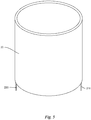
Fig. 5 is a perspective view of a cylinder in the present invention; -
Fig. 6 is a schematic diagram of an annular plate in the present invention; -
Fig. 7 is a schematic diagram of an outer extrusion circular roll and an inner extrusion circular roll in the present invention; -
Fig. 8 is a front view of the material distribution work of the present invention; -
Fig. 9 is a rear view of the material distribution work of the present invention; -
Fig. 10 is a schematic diagram of an upper connecting plate of the present invention; and -
Fig. 11 is a schematic diagram of a lower connecting plate according to the present invention. - In the figures:
top cover 10,gas discharge port 11,material inlet 12,housing 20,cylinder 21, heatmedium inlet pipe 210, heatmedium outlet pipe 211, heatmedium flow channel 212,annular groove 22,annular plate 23,toothing hole 24,first gear 25,second gear 26,upper connecting plate 27,lower connecting plate 28,hole 29,base 30,rake rod 31,rotating shaft 32,electric motor 33,rake blade 34,shaft holder 35,discharge port 36,feeding system 40,cross rod 41,feeding pipe 42,material outlet 43,material coating assembly 50, distributingcircular roll 51, distributingplate 52,material distributor 53,uniform distribution pipe 531,dispatching port 532, distributingport 54,material extrusion assembly 60,outer extrusion belt 61,inner extrusion belt 62, outer extrusioncircular roll 63, inner extrusioncircular roll 64, separationcircular roll 65,upper roller group 66,lower roller group 67, anddischarging scraper 70. - As shown in
Figs. 1 and2 , a ring dryer used for drying a slurry material comprises ahousing 20, atop cover 10 provided at the top of thehousing 20, and abase 30 provided at the bottom of thehousing 20, and further comprises afeeding system 40 into which the material to be dried flows, amaterial coating assembly 50, amaterial extrusion assembly 60, adischarging scraper 70, and at least twocylinders 21 with different radii. - As shown in
Figs 1-4 ,10 and11 , thecylinder 21 is of a cylindrical structure, and a heatmedium flow channel 212 is provided inside thecylinder 21. In the present invention, thecylinder 21 is a cylinder having a ring-shaped cavity provided inside, the ring-shaped cavity forms the heatmedium flow channel 212, or a baffle plate is arranged in the ring-shaped cavity to form the heatmedium flow channel 212. Thecylinder 21 is fixedly arranged in thehousing 20, anannular groove 22 is formed between theadjacent cylinders 21, and thecylinder 21 and thehousing 20 are coaxially arranged. Thefeeding system 40 is transversely arranged in thehousing 20 and can rotate around an axis of thehousing 20. Thefeeding system 40 is composed of across rod 41 and afeeding pipe 42 or composed of across rod 41 and a feeding disc. A pipe wall of thefeeding pipe 42 is provided with amaterial outlet 43, or the bottom of the feeding disc is provided with amaterial outlet 43, and the number of thematerial outlet 43 is equal to the number of theannular groove 22. When thefeeding system 40 is composed of thecross rod 41 and thefeeding pipe 42, the number of thecross rod 41 and of thefeeding pipe 42 is equal to the number of theannular groove 22. Eachfeeding pipe 42 is provided with amaterial outlet 43, and the material to be dried in thefeeding system 40 flows into theannular groove 22 along thematerial outlet 43. Thematerial coating assembly 50, thematerial extrusion assembly 60 and thedischarging scraper 70 are movably arranged in theannular groove 22 and can move along theannular groove 22 relative to thecylinder 21, and a blade of thedischarging scraper 70 is respectively in contact with an inner circumferential surface of thecylinder 21 and an outer circumferential surface of theadjacent cylinder 21. In the present invention, thefeeding system 40 is transversely arranged in thehousing 20 and can rotate around the axis of thehousing 20, the free end of thefeeding system 40 is connected to an upper connectingplate 27, the top of thedischarging scraper 70 is connected to the upper connectingplate 27, the top of thematerial coating assembly 50 is connected to the upper connectingplate 27, the top of thematerial extrusion assembly 60 is connected to the upper connectingplate 27, the bottom of thedischarging scraper 70 is connected to a lower connectingplate 28, the bottom of thematerial coating assembly 50 is connected to the lower connectingplate 28, and the bottom of thematerial extrusion assembly 60 is connected to thelower connecting plate 28. The upper connectingplate 27 is of a ring shape and is provided with ahole 29 for passage of thematerial outlet 43, the upper connectingplate 27 is provided withholes 29 for connecting with the top of thedischarging scraper 70, the top of thematerial coating assembly 50 and the top of thematerial extrusion assembly 60; and the lower connectingplate 28 is provided withholes 29 through which the dried material passes and enter thebase 30, the lower connectingplate 28 is of a ring shape and is provided withholes 29 for connecting with the bottom of thedischarging scraper 70, the bottom of thematerial coating assembly 50 and the bottom of thematerial extrusion assembly 60. Thefeeding system 40 and the upper connectingplate 27 can be detachably connected, can be connected by a pneumatic cylinder, or can be connected by an elastic member, such as connected by a spring. For example, when thefeeding system 40 is connected to the upper connectingplate 27 by a spring, when thefeeding system 40 is suddenly turned, the spring provides a buffer action on the activation of the upper connectingplate 27, thereby protecting thedischarging scraper 70, thematerial coating assembly 50 and thematerial extrusion assembly 60 connected to the upper connectingplate 27. Thedischarging scraper 70 is connected to the upper connectingplate 27 and the lower connectingplate 28, the blades of thedischarging scraper 70 are respectively in contact with the inner circumferential surface of thecylinder 21 and the outer circumferential surface of theadjacent cylinder 21, and the dried material on the inner circumferential surface of thecylinder 21 and on the outer circumferential surface of theadjacent cylinder 21 can be scraped off by thedischarging scraper 70. The material to be dried in thefeeding system 40 flows to theannular groove 22 along thematerial outlet 43, and under the action of an external force, thefeeding system 40, thematerial coating assembly 50, thematerial extrusion assembly 60 and thedischarging scraper 70 move along theannular groove 22 relative to thecylinder 21, and the material to be dried is coated on the inner circumferential surface of thecylinder 21 and the outer circumferential surface of theadjacent cylinder 21 by thematerial coating assembly 50. The heat medium is introduced into the heatmedium flow channel 212, and the materials to be dried on the inner circumferential surface of thecylinder 21 and the outer circumferential surface of theadjacent cylinder 21 is dried by the heat medium, and at the same time, the dried material is scraped off by thedischarging scraper 70. Thedischarging scraper 70 is of a V-shaped structure, and during the movement of thedischarging scraper 70 along theannular groove 22, the dried material on the inner circumferential surface of thecylinder 21 and on the outer circumferential surface of theadjacent cylinder 21 is simultaneously scraped off by thedischarging scraper 70. Because both the inner circumferential surface of thecylinder 21 and the outer circumferential surface of theadjacent cylinder 21 are coated with the material to be dried, the area of the material to be dried is increased, thereby improving the drying efficiency; and at the same time, during the drying, the material to be dried has less friction with the components in the present invention, thereby extending the service life of the present invention. - Specifically, as shown in
Fig. 1 , thematerial extrusion assembly 60 comprises anouter extrusion belt 61, aninner extrusion belt 62, an outer extrusioncircular roll 63 and an inner extrusioncircular roll 64. The outer extrusioncircular roll 63 drives theouter extrusion belt 61 to rotate and move along theannular groove 22, and theouter extrusion belt 61 is in contact with the inner circumferential surface of thecylinder 21, so that theouter extrusion belt 61 tightly presses the material to be dried onto the inner circumferential surface of thecylinder 21; and the inner extrusioncircular roll 64 drives theinner extrusion belt 62 to rotate and move along theannular groove 22, and theinner extrusion belt 62 is in contact with the outer circumferential surface of theadjacent cylinder 21, so that theinner extrusion belt 62 tightly presses the material to be dried onto the outer circumferential surface of theadjacent cylinder 21. Both theouter extrusion belt 61 and theinner extrusion belt 62 are made of a flexible and breathable material, which can be one or any combination of porous rubber, porous soft plastic, a porous metal sheet, a metal net, a non-metal net, metal cloth, non-metal cloth, foamed plastic, a chain plate, a bamboo mat and a straw mat. Theouter extrusion belt 61 and theinner extrusion belt 62 are respectively parallel to the circumferential walls of thecylinders 21, and a separationcircular roll 65 is provided between theouter extrusion belt 61 and theinner extrusion belt 62. Because theouter extrusion belt 61 and theinner extrusion belt 62 have the same angular velocity, and the linear velocity of theouter extrusion belt 61 is greater than the linear velocity of theinner extrusion belt 62, in order to prevent theouter extrusion belt 61 and theinner extrusion belt 62 from being damaged by extrusion and friction against each other during rotation, the separationcircular roll 65 is provided between theouter extrusion belt 61 and theinner extrusion belt 62, and theouter extrusion belt 61 and theinner extrusion belt 62 form a double-track structure. During the rotation and movement of theouter extrusion belt 61 and theinner extrusion belt 62, the material to be dried is tightly attached to the inner circumferential surface of thecylinder 21 by theouter extrusion belt 61 so as to prevent the material to be dried on the inner circumferential surface of thecylinder 21 from falling off, theinner extrusion belt 62 makes the material to be dried close to the outer circumferential surface of theadjacent cylinder 21 and prevents the material to be dried on the outer circumferential surface of theadjacent cylinder 21 from falling off. - Specifically, as shown in
Figs. 2 to 5 , thematerial coating assembly 50 comprises a pair of distributingcircular rolls 51 and a pair of distributingplates 52, the pair of distributingcircular rolls 51 being longitudinally arranged in theannular groove 22 and parallel to thehousing 20, wherein one end of onedistributing plate 52 is close to one distributingcircular roll 51, and the other end thereof forms adistributing port 54 together with the inner circumferential surface of thecylinder 21; and one end of the otherdistributing plate 52 is close to the other distributingcircular roll 51, and the other end thereof forms adistributing port 54 together with the outer circumferential surface of theadjacent cylinder 21. The included angle between thedistributing plate 52 and the inner circumferential surface of thecylinder 21 or the outer circumferential surface of theadjacent cylinder 21 can be adjusted as required to further adjust the size of the distributingport 54. When the distributingcircular roll 51 rotates and moves along theannular groove 22, the distributingcircular roll 51 extrudes the material to be dried so that the material to be dried is in the shape of a uniform sheet, and the extruded material to be dried enters from the distributingport 54 and is attached to the inner circumferential surface of thecylinder 21 or the outer circumferential surface of theadjacent cylinder 21. - As shown in
Figs. 1 ,2 and6 , anannular plate 23 is provided at the top of eachcylinder 21, and toothing holes 24 are uniformly distributed around theannular plate 23, afirst gear 25 is provided at the top of the outer extrusioncircular roll 63, asecond gear 26 is provided at the top of the inner extrusioncircular roll 64, thefirst gear 25 rotates along the toothing holes 24 of theannular plate 23, and thesecond gear 26 rotates along the toothing holes 24 of theannular plate 23. Anupper roller group 66 is provided at the top of the outer extrusioncircular roll 63 and the top of the inner extrusioncircular roll 64, and the top of the outer extrusioncircular roll 63 is connected to the top of the inner extrusioncircular roll 64 by means of theupper roller group 66; and alower roller group 67 is provided at the bottom of the outer extrusioncircular roll 63 and the bottom of the inner extrusioncircular roll 64, and the bottom of the outer extrusioncircular roll 63 is connected to the inner extrusioncircular roll 64 by means of thelower roller group 67. - As shown in
Figs. 2 ,4 and7-9 , thematerial coating assembly 50 further comprises amaterial distributor 53, thematerial distributor 53 comprises severaluniform distribution pipes 531 in parallel, thematerial outlet 43 of thefeeding system 40 is connected in a butt joint with the feeding port of theuniform distribution pipe 531 on the inner side, and theuniform distribution pipe 531 on the outer side is provided with several dispatchingports 532 in sequence from top to bottom. The direction of the arrows inFig. 8 indicates the flow direction of the material to be dried, the material to be dried flows from thematerial outlet 43 of thefeeding system 40 to the feeding port of thematerial distributor 53, and under the action of theuniform distribution pipe 531, the material to be dried is uniformly distributed in the vertical direction, so that the material to be dried can be uniformly coated on the inner circumferential surface of thecylinder 21 and the outer circumferential surface of theadjacent cylinder 21. - As shown in
Fig. 1 , the bottom of thehousing 20 is provided with a heatmedium inlet pipe 210 and a heatmedium outlet pipe 211, the heatmedium inlet pipe 210 is connected to an inlet of the heatmedium flow channel 212 of thecylinder 21, and the heat medium enters the heatmedium flow channel 212 of thecylinder 21 from the heatmedium inlet pipe 210, and the material to be dried on the inner circumferential surface of thecylinder 21 and on the outer circumferential surface of theadjacent cylinder 21 is dried by the heat medium flowing through the heatmedium flow channel 212. The heatmedium outlet pipe 211 is connected to an outlet of the heatmedium flow channel 212 of thecylinder 21. - As shown in
Fig. 1 , thetop cover 10 is provided with agas discharge port 11 and amaterial inlet 12, and thematerial inlet 12 is connected to the feeding port of thefeeding system 40. After the dried material is dried, water vapor is generated, and the water vapor is discharged from thegas discharge port 11. - As shown in
Fig. 1 , anannular rake rod 31 is provided inside thebase 30, and the shaft center of therake rod 31 is fixedly connected to the shaft center of thefeeding system 40 by means of arotating shaft 32 provided. Anelectric motor 33 is further provided inside thebase 30, and theelectric motor 33 drives the rotatingshaft 32 to rotate. - As shown in
Fig. 1 , in the present invention, therake rod 31 is connected to therotating shaft 32 by means of ashaft holder 35, several horizontally arrangedrake blades 34 are mounted on therake rod 31, and therake blades 34 are detachably connected to therake rod 31. Therake rod 31 and therake blades 34 are located inside thebase 30, and bottom ends of therake blades 34 are in contact with a bottom surface of the base 30 to move the dried material such that the dried material moves to thedischarge port 36. - As shown in
Fig. 1 , the working process of the present invention is:
a water-containing slurry material to be dried enters thefeeding system 40 from thematerial inlet 12, the material to be dried flows into thematerial distributor 53 of thematerial coating assembly 50, the material to be dried is uniformly distributed in the vertical direction by thematerial distributor 53, thefeeding system 40 drives thematerial coating assembly 50, thematerial extrusion assembly 60 and the dischargingscraper 70 to move along theannular groove 22, the material to be dried is uniformly coated onto the inner circumferential surface of thecylinder 21 and the outer circumferential surface of theadjacent cylinder 21 by thematerial coating assembly 50, and then the material to be dried is extruded and fixed by theouter extrusion belt 61 and theinner extrusion belt 62 of thematerial extrusion assembly 60; and a heat medium enters the heatmedium flow channel 212, heat is transferred to the material to be dried through the inner circumferential surface of thecylinder 21 and the outer circumferential surface of theadjacent cylinder 21 such that the moisture contained in the material to be dried is vaporized and evaporated, the water vapor is discharged from thegas discharge port 11, and the dried material is scraped off by the dischargingscraper 70 and is finally discharged out of the ring dryer from the dischargingport 36. - For a second embodiment, the difference between this embodiment and the first embodiment is in that the number of the
cylinders 21 can be set as required. In this embodiment, the number of thecylinders 21 is 2 to 30,annular grooves 22 are formed between theadjacent cylinders 21, thefeeding system 40 is provided with the same number ofmaterial outlets 43 as theannular grooves 22, the material to be dried in thefeeding system 40 flows into theannular groove 22 along the correspondingmaterial outlet 43. Thematerial coating assembly 50, thematerial extrusion assembly 60 and the dischargingscraper 70 are movably arranged in theannular groove 22 and can move along theannular groove 22 relative to thecylinder 21, and a blade of the dischargingscraper 70 is respectively in contact with an inner circumferential surface of thecylinder 21 and an outer circumferential surface of theadjacent cylinder 21. The structure of thematerial coating assembly 50 is the same as that in the first embodiment, thematerial coating assembly 50 is provided with amaterial distributor 53, the structure of thematerial distributor 53 is the same as that in the first embodiment. The structure of thematerial extrusion assembly 60 is the same as that in the first embodiment. - The content described above is merely illustrative of specific embodiments of the present invention, and it should be noted that for those of ordinary skill in the art, various improvements and modifications would have been made without departing from the principle of the present invention, and these improvements and modifications should be construed as falling within the scope of protection of the present invention.
Claims (10)
- A ring dryer, comprising a housing, a top cover provided at the top of the housing, and a base provided at the bottom of the housing, characterized by further comprising a feeding system into which a material to be dried flows, a material coating assembly, a material extrusion assembly, a discharging scraper, and at least two cylinders with different radii, wherein each of the cylinders is provided with a heat medium flow path inside, an annular groove is formed between the adjacent cylinders, and a material outlet is provided at a free end of the feeding system; the material to be dried in the feeding system flows into the annular groove along the material outlet; the material coating assembly, the material extrusion assembly and the discharging scraper are movably arranged in the annular groove and can move along the annular groove relative to the cylinders; and a blade of the discharging scraper is respectively in contact with an inner circumferential surface of the cylinder and an outer circumferential surface of the adjacent cylinder.
- The ring dryer according to claim 1, characterized in that the material extrusion assembly comprises an outer extrusion belt, an inner extrusion belt, an outer extrusion circular roll and an inner extrusion circular roll, wherein the outer extrusion circular roll drives the outer extrusion belt to rotate and move along the annular groove, and the outer extrusion belt is in contact with the inner circumferential surface of the cylinder; and the inner extrusion circular roll drives the inner extrusion belt to rotate and move along the annular groove, and the inner extrusion belt is in contact with the outer circumferential surface of the adjacent cylinder.
- The ring dryer according to claim 2, characterized in that the outer extrusion belt and the inner extrusion belt are arranged parallel to each other, and a separation circular roll is provided between the outer extrusion belt and the inner extrusion belt.
- The ring dryer according to claim 1, characterized in that the material coating assembly comprises a pair of distributing circular rolls and a pair of distributing plates, the pair of distributing circular rolls being longitudinally arranged in the annular groove and parallel to an axis of the housing, wherein one end of one distributing plate is close to one distributing circular roll, and the other end thereof forms a distributing port together with the inner circumferential surface of the cylinder; and one end of the other distributing plate is close to the other distributing circular roll, and the other end thereof forms a distributing port together with the outer circumferential surface of the adjacent cylinder.
- The ring dryer according to claim 4, characterized in that the material coating assembly further comprises a material distributor, wherein the material distributor comprises several uniform distribution pipes in parallel, the material outlet of the feeding system is connected in a butt joint with a feeding port of the uniform distribution pipe on the inner side, and the uniform distribution pipe on the outer side is provided with several dispatching ports in sequence from top to bottom.
- The ring dryer according to claim 1, characterized in that an annular plate is provided at the top of the cylinder, toothing holes are uniformly distributed around the annular plate, a first gear is provided at the top of the outer extrusion circular roll, a second gear is provided at the top of the inner extrusion circular roll, the first gear rotates along the toothing holes of the annular plate, and the second gear rotates along the toothing holes of the adjacent annular plate.
- The ring dryer according to any one of claims 1 to 6, characterized in that the feeding system is transversely arranged in the housing and can rotate around the axis of the housing, the free end of the feeding system is connected to an upper connecting plate, the top of the discharging scraper is connected to the upper connecting plate, the top of the material coating assembly is connected to the upper connecting plate, the top of the material extrusion assembly is connected to the upper connecting plate, the bottom of the discharging scraper is connected to a lower connecting plate, the bottom of the material coating assembly is connected to the lower connecting plate, and the bottom of the material extrusion assembly is connected to the lower connecting plate.
- The ring dryer according to any one of claims 1 to 6, characterized in that the ring dryer further comprises a rotating shaft, wherein an annular rake rod is provided inside the base, and the rake rod is fixedly connected to the feeding system by means of the rotating shaft.
- The ring dryer according to any one of claims 1 to 6, characterized in that the bottom of the housing is provided with a heat medium inlet pipe and a heat medium outlet pipe, wherein the heat medium inlet pipe is connected to an inlet of the heat medium flow channel of the cylinder, and the heat medium outlet pipe is connected to an outlet of the heat medium flow channel of the cylinder.
- The ring dryer according to any one of claims 1 to 6, characterized in that the top cover is provided with a gas discharge port and a material inlet, and the material inlet is connected to the feeding port of the feeding system.
Applications Claiming Priority (2)
| Application Number | Priority Date | Filing Date | Title |
|---|---|---|---|
| CN201710970873.9A CN107617225B (en) | 2017-10-18 | 2017-10-18 | Ring type drying machine |
| PCT/CN2018/099550 WO2019076107A1 (en) | 2017-10-18 | 2018-08-09 | Circular ring type drying machine |
Publications (2)
| Publication Number | Publication Date |
|---|---|
| EP3698860A1 true EP3698860A1 (en) | 2020-08-26 |
| EP3698860A4 EP3698860A4 (en) | 2021-07-21 |
Family
ID=61092500
Family Applications (1)
| Application Number | Title | Priority Date | Filing Date |
|---|---|---|---|
| EP18868926.9A Withdrawn EP3698860A4 (en) | 2017-10-18 | 2018-08-09 | Circular ring type drying machine |
Country Status (6)
| Country | Link |
|---|---|
| US (1) | US20200223100A1 (en) |
| EP (1) | EP3698860A4 (en) |
| JP (1) | JP2020533558A (en) |
| KR (1) | KR20200041931A (en) |
| CN (1) | CN107617225B (en) |
| WO (1) | WO2019076107A1 (en) |
Cited By (1)
| Publication number | Priority date | Publication date | Assignee | Title |
|---|---|---|---|---|
| CN112873618A (en) * | 2021-02-03 | 2021-06-01 | 浙江联颖科技有限公司 | Masterbatch drying device |
Families Citing this family (11)
| Publication number | Priority date | Publication date | Assignee | Title |
|---|---|---|---|---|
| CN107617225B (en) * | 2017-10-18 | 2020-05-12 | 深圳佰思嘉科技有限公司 | Ring type drying machine |
| CN112146413A (en) * | 2020-09-29 | 2020-12-29 | 深圳佰思嘉科技有限公司 | A new type of ring dryer |
| CN113263658B (en) * | 2021-05-18 | 2022-09-20 | 阔丹凌云汽车胶管有限公司 | Material drying device for rubber processing |
| KR102689911B1 (en) | 2021-12-27 | 2024-07-31 | 정원일 | Smart human sterilizer |
| CN114944538B (en) * | 2022-07-07 | 2024-04-16 | 贵州航盛锂能科技有限公司 | Sodium ion battery ceramic diaphragm and preparation method thereof |
| CN115355702B (en) * | 2022-08-15 | 2024-04-23 | 浙江森林生物科技有限公司 | Drying equipment and method for bamboo powder raw material for degradable product |
| CN115654899B (en) * | 2022-11-11 | 2024-08-13 | 洛阳融惠化工科技有限公司 | Shutter type moving bed drying equipment and drying method thereof |
| CN116058451B (en) * | 2023-02-08 | 2025-01-14 | 湖南宝东农牧科技股份有限公司 | Chicken feed comprehensive processing system |
| CN118404788B (en) * | 2024-05-24 | 2025-02-18 | 厦门宝益科技有限公司 | A flame-retardant polypropylene microporous composite material preparation extrusion molding platform |
| CN119245302B (en) * | 2024-12-03 | 2025-03-11 | 云南省林业和草原科学院 | High temperature baking equipment for processing peeled walnuts |
| CN119803045B (en) * | 2025-03-17 | 2025-06-20 | 福州金安道农机有限公司 | Even high-efficient grain drier of drying |
Family Cites Families (10)
| Publication number | Priority date | Publication date | Assignee | Title |
|---|---|---|---|---|
| BE566415A (en) * | 1957-04-05 | |||
| JPS556072U (en) * | 1978-06-30 | 1980-01-16 | ||
| JPS56106801U (en) * | 1980-01-18 | 1981-08-19 | ||
| SU1581336A1 (en) * | 1987-03-16 | 1990-07-30 | Всесоюзный Научно-Исследовательский Институт Химических Реактивов И Особо Чистых Химических Веществ | Climbing-film rotary evaporator |
| CN2080416U (en) * | 1989-06-02 | 1991-07-10 | 陈浩 | Multilayer film-scraping evaporator |
| SU1678407A1 (en) * | 1989-12-05 | 1991-09-23 | Киевский Политехнический Институт Им.50-Летия Великой Октябрьской Социалистической Революции | Centrifugal distiller |
| US8858758B2 (en) * | 2010-07-21 | 2014-10-14 | Aquaback Technologies, Inc. | Distiller |
| CN202070179U (en) * | 2011-05-11 | 2011-12-14 | 无锡捷尔机械有限公司 | Movable side stopping plate of double-rotary-drum dryer pond |
| CN207591309U (en) * | 2017-10-18 | 2018-07-10 | 深圳佰思嘉科技有限公司 | Circular ring type drying machine |
| CN107617225B (en) * | 2017-10-18 | 2020-05-12 | 深圳佰思嘉科技有限公司 | Ring type drying machine |
-
2017
- 2017-10-18 CN CN201710970873.9A patent/CN107617225B/en active Active
-
2018
- 2018-08-09 JP JP2020515898A patent/JP2020533558A/en active Pending
- 2018-08-09 EP EP18868926.9A patent/EP3698860A4/en not_active Withdrawn
- 2018-08-09 WO PCT/CN2018/099550 patent/WO2019076107A1/en not_active Ceased
- 2018-08-09 KR KR1020207007473A patent/KR20200041931A/en not_active Ceased
- 2018-08-09 US US16/649,977 patent/US20200223100A1/en not_active Abandoned
Cited By (1)
| Publication number | Priority date | Publication date | Assignee | Title |
|---|---|---|---|---|
| CN112873618A (en) * | 2021-02-03 | 2021-06-01 | 浙江联颖科技有限公司 | Masterbatch drying device |
Also Published As
| Publication number | Publication date |
|---|---|
| CN107617225A (en) | 2018-01-23 |
| CN107617225B (en) | 2020-05-12 |
| KR20200041931A (en) | 2020-04-22 |
| WO2019076107A1 (en) | 2019-04-25 |
| EP3698860A4 (en) | 2021-07-21 |
| US20200223100A1 (en) | 2020-07-16 |
| JP2020533558A (en) | 2020-11-19 |
Similar Documents
| Publication | Publication Date | Title |
|---|---|---|
| EP3698860A1 (en) | Circular ring type drying machine | |
| CN201680678U (en) | Municipal domestic waste roller drier | |
| CN101865598B (en) | Rotary drum dryer | |
| CN112146413A (en) | A new type of ring dryer | |
| CN209893868U (en) | A pellet tumble dryer | |
| CN103307863A (en) | Material dryer | |
| CN203928688U (en) | Blade dryer and paddle blade structure thereof | |
| CN111238208B (en) | Chemical fertilizer drying device for agricultural production | |
| CN120846047B (en) | Wood flour drying device | |
| CN207591309U (en) | Circular ring type drying machine | |
| CN109654834B (en) | Drum-type heat exchange equipment for tertiary butyl acrylamide production | |
| CN203687541U (en) | High-efficiency heat conduction oil type roller drying device | |
| CN201104090Y (en) | Furnace drying grille for revolving drier | |
| CN202048763U (en) | Crystal inorganic salt reverse flow uniform dryer | |
| CN215278302U (en) | A protective film cooling roll | |
| KR102301898B1 (en) | Indirect heating tube rotary dryer and drying method | |
| CN2241312Y (en) | A rotary cylinder drying device with special-shaped lifting board | |
| CN210374395U (en) | Drying machine | |
| CN212024791U (en) | Flaker and rotary drum thereof | |
| CN114808083A (en) | Dewatering equipment for electrophoretic coating | |
| CN204854209U (en) | Drum -type chemical fertilizer drying equipment | |
| CN208504961U (en) | A kind of adjustable hot-air through type dryer of air knife | |
| CN209558826U (en) | Concrete additive drying unit | |
| CN105783457A (en) | High-efficiency circulating roller drying system | |
| CN220871402U (en) | Material distribution device for film scraper double-roller dryer |
Legal Events
| Date | Code | Title | Description |
|---|---|---|---|
| STAA | Information on the status of an ep patent application or granted ep patent |
Free format text: STATUS: THE INTERNATIONAL PUBLICATION HAS BEEN MADE |
|
| PUAI | Public reference made under article 153(3) epc to a published international application that has entered the european phase |
Free format text: ORIGINAL CODE: 0009012 |
|
| STAA | Information on the status of an ep patent application or granted ep patent |
Free format text: STATUS: REQUEST FOR EXAMINATION WAS MADE |
|
| 17P | Request for examination filed |
Effective date: 20200327 |
|
| AK | Designated contracting states |
Kind code of ref document: A1 Designated state(s): AL AT BE BG CH CY CZ DE DK EE ES FI FR GB GR HR HU IE IS IT LI LT LU LV MC MK MT NL NO PL PT RO RS SE SI SK SM TR |
|
| AX | Request for extension of the european patent |
Extension state: BA ME |
|
| DAV | Request for validation of the european patent (deleted) | ||
| DAX | Request for extension of the european patent (deleted) | ||
| RIN1 | Information on inventor provided before grant (corrected) |
Inventor name: QIN, JIANZHOU Inventor name: QIN, YUFANG Inventor name: QIN, JIANWU |
|
| A4 | Supplementary search report drawn up and despatched |
Effective date: 20210621 |
|
| RIC1 | Information provided on ipc code assigned before grant |
Ipc: B01D 1/24 20060101AFI20210615BHEP Ipc: B01D 1/30 20060101ALI20210615BHEP Ipc: F26B 3/20 20060101ALI20210615BHEP Ipc: F26B 9/06 20060101ALI20210615BHEP Ipc: F26B 23/10 20060101ALI20210615BHEP Ipc: F26B 25/00 20060101ALI20210615BHEP Ipc: F26B 25/04 20060101ALI20210615BHEP |
|
| STAA | Information on the status of an ep patent application or granted ep patent |
Free format text: STATUS: THE APPLICATION IS DEEMED TO BE WITHDRAWN |
|
| 18D | Application deemed to be withdrawn |
Effective date: 20220119 |