EP3698719A1 - Mammography apparatus and program - Google Patents
Mammography apparatus and program Download PDFInfo
- Publication number
- EP3698719A1 EP3698719A1 EP20155500.0A EP20155500A EP3698719A1 EP 3698719 A1 EP3698719 A1 EP 3698719A1 EP 20155500 A EP20155500 A EP 20155500A EP 3698719 A1 EP3698719 A1 EP 3698719A1
- Authority
- EP
- European Patent Office
- Prior art keywords
- image
- candidate
- similarity degree
- scout
- diagnostic
- Prior art date
- Legal status (The legal status is an assumption and is not a legal conclusion. Google has not performed a legal analysis and makes no representation as to the accuracy of the status listed.)
- Granted
Links
Images




Classifications
-
- A—HUMAN NECESSITIES
- A61—MEDICAL OR VETERINARY SCIENCE; HYGIENE
- A61B—DIAGNOSIS; SURGERY; IDENTIFICATION
- A61B6/00—Apparatus or devices for radiation diagnosis; Apparatus or devices for radiation diagnosis combined with radiation therapy equipment
- A61B6/50—Apparatus or devices for radiation diagnosis; Apparatus or devices for radiation diagnosis combined with radiation therapy equipment specially adapted for specific body parts; specially adapted for specific clinical applications
- A61B6/502—Apparatus or devices for radiation diagnosis; Apparatus or devices for radiation diagnosis combined with radiation therapy equipment specially adapted for specific body parts; specially adapted for specific clinical applications for diagnosis of breast, i.e. mammography
-
- A—HUMAN NECESSITIES
- A61—MEDICAL OR VETERINARY SCIENCE; HYGIENE
- A61B—DIAGNOSIS; SURGERY; IDENTIFICATION
- A61B6/00—Apparatus or devices for radiation diagnosis; Apparatus or devices for radiation diagnosis combined with radiation therapy equipment
- A61B6/02—Arrangements for diagnosis sequentially in different planes; Stereoscopic radiation diagnosis
- A61B6/025—Tomosynthesis
-
- A—HUMAN NECESSITIES
- A61—MEDICAL OR VETERINARY SCIENCE; HYGIENE
- A61B—DIAGNOSIS; SURGERY; IDENTIFICATION
- A61B6/00—Apparatus or devices for radiation diagnosis; Apparatus or devices for radiation diagnosis combined with radiation therapy equipment
- A61B6/46—Arrangements for interfacing with the operator or the patient
- A61B6/461—Displaying means of special interest
- A61B6/463—Displaying means of special interest characterised by displaying multiple images or images and diagnostic data on one display
-
- A—HUMAN NECESSITIES
- A61—MEDICAL OR VETERINARY SCIENCE; HYGIENE
- A61B—DIAGNOSIS; SURGERY; IDENTIFICATION
- A61B6/00—Apparatus or devices for radiation diagnosis; Apparatus or devices for radiation diagnosis combined with radiation therapy equipment
- A61B6/46—Arrangements for interfacing with the operator or the patient
- A61B6/467—Arrangements for interfacing with the operator or the patient characterised by special input means
- A61B6/469—Arrangements for interfacing with the operator or the patient characterised by special input means for selecting a region of interest [ROI]
-
- A—HUMAN NECESSITIES
- A61—MEDICAL OR VETERINARY SCIENCE; HYGIENE
- A61B—DIAGNOSIS; SURGERY; IDENTIFICATION
- A61B6/00—Apparatus or devices for radiation diagnosis; Apparatus or devices for radiation diagnosis combined with radiation therapy equipment
- A61B6/48—Diagnostic techniques
- A61B6/488—Diagnostic techniques involving pre-scan acquisition
-
- A—HUMAN NECESSITIES
- A61—MEDICAL OR VETERINARY SCIENCE; HYGIENE
- A61B—DIAGNOSIS; SURGERY; IDENTIFICATION
- A61B6/00—Apparatus or devices for radiation diagnosis; Apparatus or devices for radiation diagnosis combined with radiation therapy equipment
- A61B6/52—Devices using data or image processing specially adapted for radiation diagnosis
- A61B6/5211—Devices using data or image processing specially adapted for radiation diagnosis involving processing of medical diagnostic data
- A61B6/5217—Devices using data or image processing specially adapted for radiation diagnosis involving processing of medical diagnostic data extracting a diagnostic or physiological parameter from medical diagnostic data
-
- A—HUMAN NECESSITIES
- A61—MEDICAL OR VETERINARY SCIENCE; HYGIENE
- A61B—DIAGNOSIS; SURGERY; IDENTIFICATION
- A61B6/00—Apparatus or devices for radiation diagnosis; Apparatus or devices for radiation diagnosis combined with radiation therapy equipment
- A61B6/52—Devices using data or image processing specially adapted for radiation diagnosis
- A61B6/5211—Devices using data or image processing specially adapted for radiation diagnosis involving processing of medical diagnostic data
- A61B6/5229—Devices using data or image processing specially adapted for radiation diagnosis involving processing of medical diagnostic data combining image data of a patient, e.g. combining a functional image with an anatomical image
- A61B6/5235—Devices using data or image processing specially adapted for radiation diagnosis involving processing of medical diagnostic data combining image data of a patient, e.g. combining a functional image with an anatomical image combining images from the same or different ionising radiation imaging techniques, e.g. PET and CT
-
- G—PHYSICS
- G06—COMPUTING OR CALCULATING; COUNTING
- G06F—ELECTRIC DIGITAL DATA PROCESSING
- G06F18/00—Pattern recognition
- G06F18/20—Analysing
- G06F18/22—Matching criteria, e.g. proximity measures
-
- G—PHYSICS
- G06—COMPUTING OR CALCULATING; COUNTING
- G06T—IMAGE DATA PROCESSING OR GENERATION, IN GENERAL
- G06T7/00—Image analysis
- G06T7/0002—Inspection of images, e.g. flaw detection
- G06T7/0012—Biomedical image inspection
-
- G—PHYSICS
- G06—COMPUTING OR CALCULATING; COUNTING
- G06T—IMAGE DATA PROCESSING OR GENERATION, IN GENERAL
- G06T7/00—Image analysis
- G06T7/0002—Inspection of images, e.g. flaw detection
- G06T7/0012—Biomedical image inspection
- G06T7/0014—Biomedical image inspection using an image reference approach
-
- G—PHYSICS
- G06—COMPUTING OR CALCULATING; COUNTING
- G06V—IMAGE OR VIDEO RECOGNITION OR UNDERSTANDING
- G06V10/00—Arrangements for image or video recognition or understanding
- G06V10/20—Image preprocessing
- G06V10/22—Image preprocessing by selection of a specific region containing or referencing a pattern; Locating or processing of specific regions to guide the detection or recognition
- G06V10/235—Image preprocessing by selection of a specific region containing or referencing a pattern; Locating or processing of specific regions to guide the detection or recognition based on user input or interaction
-
- G—PHYSICS
- G06—COMPUTING OR CALCULATING; COUNTING
- G06V—IMAGE OR VIDEO RECOGNITION OR UNDERSTANDING
- G06V10/00—Arrangements for image or video recognition or understanding
- G06V10/70—Arrangements for image or video recognition or understanding using pattern recognition or machine learning
- G06V10/74—Image or video pattern matching; Proximity measures in feature spaces
- G06V10/75—Organisation of the matching processes, e.g. simultaneous or sequential comparisons of image or video features; Coarse-fine approaches, e.g. multi-scale approaches; using context analysis; Selection of dictionaries
-
- A—HUMAN NECESSITIES
- A61—MEDICAL OR VETERINARY SCIENCE; HYGIENE
- A61B—DIAGNOSIS; SURGERY; IDENTIFICATION
- A61B6/00—Apparatus or devices for radiation diagnosis; Apparatus or devices for radiation diagnosis combined with radiation therapy equipment
- A61B6/04—Positioning of patients; Tiltable beds or the like
- A61B6/0407—Supports, e.g. tables or beds, for the body or parts of the body
- A61B6/0414—Supports, e.g. tables or beds, for the body or parts of the body with compression means
-
- A—HUMAN NECESSITIES
- A61—MEDICAL OR VETERINARY SCIENCE; HYGIENE
- A61B—DIAGNOSIS; SURGERY; IDENTIFICATION
- A61B8/00—Diagnosis using ultrasonic, sonic or infrasonic waves
- A61B8/08—Clinical applications
- A61B8/0825—Clinical applications for diagnosis of the breast, e.g. mammography
-
- A—HUMAN NECESSITIES
- A61—MEDICAL OR VETERINARY SCIENCE; HYGIENE
- A61B—DIAGNOSIS; SURGERY; IDENTIFICATION
- A61B8/00—Diagnosis using ultrasonic, sonic or infrasonic waves
- A61B8/52—Devices using data or image processing specially adapted for diagnosis using ultrasonic, sonic or infrasonic waves
- A61B8/5215—Devices using data or image processing specially adapted for diagnosis using ultrasonic, sonic or infrasonic waves involving processing of medical diagnostic data
- A61B8/5223—Devices using data or image processing specially adapted for diagnosis using ultrasonic, sonic or infrasonic waves involving processing of medical diagnostic data for extracting a diagnostic or physiological parameter from medical diagnostic data
-
- G—PHYSICS
- G06—COMPUTING OR CALCULATING; COUNTING
- G06T—IMAGE DATA PROCESSING OR GENERATION, IN GENERAL
- G06T2200/00—Indexing scheme for image data processing or generation, in general
- G06T2200/24—Indexing scheme for image data processing or generation, in general involving graphical user interfaces [GUIs]
-
- G—PHYSICS
- G06—COMPUTING OR CALCULATING; COUNTING
- G06T—IMAGE DATA PROCESSING OR GENERATION, IN GENERAL
- G06T2207/00—Indexing scheme for image analysis or image enhancement
- G06T2207/10—Image acquisition modality
- G06T2207/10004—Still image; Photographic image
- G06T2207/10012—Stereo images
-
- G—PHYSICS
- G06—COMPUTING OR CALCULATING; COUNTING
- G06T—IMAGE DATA PROCESSING OR GENERATION, IN GENERAL
- G06T2207/00—Indexing scheme for image analysis or image enhancement
- G06T2207/10—Image acquisition modality
- G06T2207/10116—X-ray image
-
- G—PHYSICS
- G06—COMPUTING OR CALCULATING; COUNTING
- G06T—IMAGE DATA PROCESSING OR GENERATION, IN GENERAL
- G06T2207/00—Indexing scheme for image analysis or image enhancement
- G06T2207/30—Subject of image; Context of image processing
- G06T2207/30004—Biomedical image processing
- G06T2207/30068—Mammography; Breast
-
- G—PHYSICS
- G06—COMPUTING OR CALCULATING; COUNTING
- G06T—IMAGE DATA PROCESSING OR GENERATION, IN GENERAL
- G06T2207/00—Indexing scheme for image analysis or image enhancement
- G06T2207/30—Subject of image; Context of image processing
- G06T2207/30004—Biomedical image processing
- G06T2207/30096—Tumor; Lesion
-
- G—PHYSICS
- G06—COMPUTING OR CALCULATING; COUNTING
- G06T—IMAGE DATA PROCESSING OR GENERATION, IN GENERAL
- G06T2207/00—Indexing scheme for image analysis or image enhancement
- G06T2207/30—Subject of image; Context of image processing
- G06T2207/30204—Marker
-
- G—PHYSICS
- G06—COMPUTING OR CALCULATING; COUNTING
- G06V—IMAGE OR VIDEO RECOGNITION OR UNDERSTANDING
- G06V2201/00—Indexing scheme relating to image or video recognition or understanding
- G06V2201/03—Recognition of patterns in medical or anatomical images
-
- G—PHYSICS
- G16—INFORMATION AND COMMUNICATION TECHNOLOGY [ICT] SPECIALLY ADAPTED FOR SPECIFIC APPLICATION FIELDS
- G16H—HEALTHCARE INFORMATICS, i.e. INFORMATION AND COMMUNICATION TECHNOLOGY [ICT] SPECIALLY ADAPTED FOR THE HANDLING OR PROCESSING OF MEDICAL OR HEALTHCARE DATA
- G16H30/00—ICT specially adapted for the handling or processing of medical images
- G16H30/40—ICT specially adapted for the handling or processing of medical images for processing medical images, e.g. editing
Definitions
- the present invention relates to a mammography apparatus for imaging a mamma of a test subject using radiation such as X-rays, and a program for driving the mammography apparatus.
- the mammography apparatus is used for breast cancer screening, a biological tissue examination (hereinafter, referred to as a biopsy), and the like. Since the breast cancer is closely associated with a calcification, in the breast cancer screening, it is common to search for a calcification using an image captured by using the mammography apparatus (hereinafter, referred to as a mammography image) and to diagnose whether the found a calcification is associated with the breast cancer. Then, in a case where a calcification that may be associated with the breast cancer is found, a biopsy is performed. The biopsy is for a definitive diagnosis.
- a mammography image an image captured by using the mammography apparatus
- JP2013-501290A a method of positioning two images for medical use is known ( JP2013-501290A ).
- an image analysis method having functions of displaying a 3D rendering model and performing centering around the coordinates relating to the diagnostic findings.
- a biopsy target specified using an image used for diagnosis (hereinafter, referred to as a diagnostic image) has to be searched for again using an image captured in case of performing a biopsy (hereinafter, referred to as a biopsy image), but there was no auxiliary means to find the target, which is specified using the diagnostic image, in the biopsy image. Therefore, during the biopsy, an incorrect target (target different from the target specified using the diagnostic image) may be collected, which becomes a burden on a test subject.
- An object of the invention is to specify a candidate for a target in a biopsy image using a diagnostic image in a case where a biopsy is performed.
- a mammography apparatus comprises a diagnostic image acquisition unit that acquires a diagnostic image which is a mammography image used for diagnosis and in which a target of a biological tissue examination is marked; a scout image acquisition unit that acquires a scout image obtained by imaging a mamma undergoing the biological tissue examination from a specific direction; and a display unit that highlights a candidate for the biological tissue examination in the scout image which matches at least the marked target in the diagnostic image.
- a tissue similarity degree calculation unit recognizes the "candidate” in the scout image and calculates a tissue similarity degree which is a similarity degree between the "candidate” in the scout image and the marked target in the diagnostic image, and a determination unit determines whether the candidate matches the target using the tissue similarity degree.
- the display unit displays a value of the tissue similarity degree.
- the display unit highlights the "candidate" of which the tissue similarity degree is equal to or greater than a first threshold.
- the mammography apparatus includes an image similarity degree calculation unit that calculates an image similarity degree which is a similarity degree for a partial image or a whole image between the diagnostic image and the scout image, and the display unit determines whether to highlight the "candidate" using the image similarity degree.
- the display unit highlights the "candidate” in a case where the image similarity degree is equal to or greater than a second threshold.
- the mammography apparatus includes a warning notification unit that notifies of a warning at least in a case where there is no candidate to be highlighted by the display unit.
- warning notification unit prompts recapturing of the scout image.
- the display unit displays a position of the "candidate" in the scout image which matches the marked target in the diagnostic image, by highlighting.
- the mammography apparatus includes a stereo image acquisition unit that acquires a stereo image obtained by imaging the mamma undergoing the biological tissue examination from an inclination direction which is inclined with respect to the specific direction from which the scout image is captured; and a stereo image recognition unit that recognizes the "candidate” in the stereo image, and associates the "candidate” in the stereo image with the marked target in the diagnostic image or the “candidate” in the scout image which matches the marked target in the diagnostic image, and the display unit highlights the candidate matching the marked target in the diagnostic image among the candidates in the stereo image.
- the stereo image recognition unit calculates a second tissue similarity degree which is a similarity degree between the "candidate” in the stereo image and the marked target in the diagnostic image or the "candidate” in the scout image which matches the marked target in the diagnostic image, and the display unit highlights at least the "candidate” having the highest second tissue similarity degree among the "candidates” in the stereo image.
- the stereo image acquisition unit prohibits capturing of the stereo image in a case where there is no "candidate” in the scout image, which matches the marked target in the diagnostic image.
- the mammography apparatus includes a tomosynthesis image acquisition unit that acquires a series of tomosynthesis images of the mamma undergoing the biological tissue examination; and a tomosynthesis image recognition unit that recognizes the target of the biological tissue examination in the series of tomosynthesis images, and associates the candidate in each tomosynthesis image with the marked target in the diagnostic image or the candidate in the scout image which matches the marked target in the diagnostic image, and the display unit selects and displays some of the tomosynthesis images from among the series of tomosynthesis images using a recognition result of the tomosynthesis image recognition unit.
- the tomosynthesis image recognition unit calculates a third tissue similarity degree which is a similarity degree between the "candidate” in the tomosynthesis image and the marked target in the diagnostic image or the "candidate” in the scout image which matches the marked target in the diagnostic image, and the display unit displays the tomosynthesis image including at least a calcification having the highest third tissue similarity degree among the "candidates” in the series of tomosynthesis images.
- the tomosynthesis image acquisition unit prohibits imaging for obtaining the tomosynthesis image in a case where there is no "candidate" in the scout image, which matches the marked target in the diagnostic image.
- the mammography apparatus includes a warning notification unit that notifies of a warning to prompt marking of the calcification in a case where there is no marked target in the diagnostic image.
- the mammography apparatus includes a marking unit that recognizes the "candidates” in the diagnostic image and marks some or all of the recognized "candidates” in a case where there is no marked target in the diagnostic image.
- the scout image acquisition unit acquires the scout image of which at least one or a plurality conditions among use or non-use of a grid, a tube voltage of a radiation tube, and a dose of radiation are the same as the diagnostic image.
- the scout image acquisition unit acquires the scout image in which a grid having the same grid ratio as a grid used for capturing the diagnostic image is used in a case where the scout image in which the grid is used is acquired.
- the scout image acquisition unit acquires the scout image subjected to the same image processing as the diagnostic image.
- the tissue similarity degree calculation unit recognizes the "candidate" in the scout image by pattern matching and calculates the tissue similarity degree.
- the tissue similarity degree calculation unit outputs a probability that the candidate for the biological tissue examination in the scout image is the marked target in the diagnostic image, as the tissue similarity degree by using a learned model that outputs the probability by inputting the diagnostic image in which the target of the biological tissue examination is marked and the scout image.
- a program is a program driving a mammography apparatus including a display unit that highlights a candidate for a biological tissue examination in a biopsy image captured in the biological tissue examination, and the program causes an arithmetic operation device of the mammography apparatus or an arithmetic operation device cooperating with the mammography apparatus to calculate the tissue similarity degree used for determining the "candidate” to be highlighted by the display unit, by using a learned model that outputs a position of the "candidate” in the biopsy image and a tissue similarity degree which is a similarity degree between the "candidate” in the biopsy image and a marked target in the diagnostic image by inputting the biopsy image and the diagnostic image in which the target of the biological tissue examination is marked.
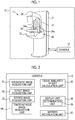
- a mammography apparatus 10 includes an apparatus body 11 which images a mamma of a test subject using X-rays, and a console 12 which controls the apparatus body 11.
- the apparatus body 11 includes a prop 31, an X-ray generation part 32, an imaging stand 33 with a built-in X-ray imaging part, a pressing plate 36, a lifting/lowering part 37, and the like.
- the X-ray generation part 32 and the imaging stand 33 are integrated and configure a movable part 40 which adjusts a position according to a test subject in the apparatus body 11.
- the imaging stand 33 is a stage on which a mamma of a test subject is placed, and clamps the mamma of the test subject using the pressing plate 36 during imaging.
- the X-ray imaging part (not shown) built in the imaging stand 33 includes a flat panel detector (FPD) or the like which images a subject using, for example, radiation, and a grid for removing scattered rays (stationary Lysholm blende or mobile bucky blende).
- the mammography apparatus 10 has multiple types of grids which are replaceable according to the imaging conditions, and can perform imaging in which the grid is not used.
- a grip part 34a that the test subject grips with the right hand and a grip part 34b that the test subject grips with the left hand are attached to the imaging stand 33.
- the grip part 34a and the grip part 34b are a so-called arm rest.
- the pressing plate 36 presses the mamma of the test subject, which is placed on the imaging stand 33, and makes the mamma flat. This is to reduce the overlap of normal mammary glands and make it easier to find a candidate for a lesion such as a calcification.
- the lifting/lowering part 37 lifts or lowers the pressing plate 36 with respect to the imaging stand 33. In this manner, the lifting/lowering part 37 supports the pressing plate 36 approximately parallel to the imaging stand 33 and at a specific distance according to the thickness of the mamma.
- the movable part 40 is rotatable within a predetermined angle range while maintaining the relative position and direction of the X-ray generation part 32 and the imaging stand 33. Therefore, the apparatus body 11 can perform imaging with the imaging stand 33 being disposed horizontally or the imaging stand 33 being disposed obliquely with respect to the horizontal. Specifically, the apparatus body 11 can perform craniocaudal imaging (CC imaging) in which a mamma is imaged from a craniocaudal direction, with the imaging stand 33 being disposed horizontally. In addition, the apparatus body 11 can perform mediolateral oblique imaging (MLO imaging) in which a mamma is imaged from a mediolateral oblique direction, with the imaging stand 33 being disposed obliquely.
- CC imaging craniocaudal imaging
- MLO imaging mediolateral oblique imaging
- the X-ray generation part 32 of the movable part 40 is rotatable within a predetermined range while the positions of the imaging stand 33 and the pressing plate 36 are fixed.
- the apparatus body 11 can perform so-called stereo imaging and tomosynthesis imaging.
- the stereo imaging is an imaging aspect in which the mamma of the test subject fixed at specific position and direction (for example, position and direction of the CC imaging) is imaged from one or a plurality of inclination directions with different inclination angles and a fluoroscopic image from the inclination direction (hereinafter, referred to as a stereo image) is obtained.
- the tomosynthesis imaging is an imaging aspect in which a tomographic image (hereinafter, referred to as a tomosynthesis image) of a mamma of a test subject is obtained using images of the mamma of the test subject fixed at the specific position and direction, which are captured from a plurality of inclination directions.
- a tomographic image hereinafter, referred to as a tomosynthesis image
- the console 12 includes a diagnostic image acquisition unit 51, a scout image acquisition unit 52, a stereo image acquisition unit 53, a tomosynthesis image acquisition unit 54, a tissue similarity degree calculation unit 55, a display unit 56, and a warning notification unit 57.
- the diagnostic image acquisition unit 51 acquires diagnostic images from a radiology information system (RIS), a picture archiving and communication system (PACS), a hospital information system (HIS), or the like which is directly or indirectly connected to the mammography apparatus 10.
- the diagnostic image is a mammography image used for diagnosis, and a mammography image in which a target of the biological tissue examination is marked is obtained.
- the target of the biological tissue examination is simply a biopsy target, for example, a calcification.
- the target of the biological tissue examination is a "calcification" and the target of the biological tissue examination is simply referred to as a calcification. Note that, for a lesion or a portion that could be a lesion, regardless of a specific form of the tissue or structure thereof, a tissue or the like other than calcifications can be a target of the biological tissue examination.
- CC imaging and MLO imaging are performed for diagnosis, and thus the diagnostic images acquired by the diagnostic image acquisition unit 51 are CC images and MLO images in which a calcification as the biopsy target is marked.
- the marking for a calcification means that information specifying the position of a calcification as the biopsy target is attached to a partial or entire diagnostic image. For example, attaching a marker, a label, or the like to a specific calcification in the diagnostic image to specify the position of the calcification and/or recording information such as coordinates indicating the position or the range of a specific calcification in association with the diagnostic image corresponds to the marking for a calcification.
- a doctor attaches a specific marker to the diagnostic image, and the coordinates of the position of the marker are recorded in the header or the like of the diagnostic image.
- a CC image 61 as one of the diagnostic images is composed of a left mamma image 62 obtained by imaging the left mamma of the test subject from the CC direction, and a right mamma image 63 obtained by imaging the right mamma of the test subject from the CC direction.
- the doctor diagnoses that a biopsy is necessary for the calcification 65B among the calcifications 65A to 65C and marks the calcification 65B by attaching a marker 66, for example.
- an MLO image 71 as one of the diagnostic images is composed of a left mamma image 72 obtained by imaging the left mamma of the test subject from an inclination direction inclined by a predetermined angle (hereinafter, referred to as an MLO direction), and a right mamma image 73 obtained by imaging the right mamma of the test subject from the MLO direction.
- an MLO direction a predetermined angle
- a right mamma image 73 obtained by imaging the right mamma of the test subject from the MLO direction.
- the calcification 75A corresponds to the calcification 65A in the CC image 61
- the calcification 75B corresponds to the calcification 65B in the CC image 61
- the calcification 75C corresponds to the calcification 65C in the CC image 61.
- the doctor marks the calcification 75B by attaching a marker 76 to the calcification 75B of the MLO image 71.
- the scout image acquisition unit 52 acquires a scout image obtained by imaging the mamma undergoing the biological tissue examination from a specific direction. More specifically, in case of performing a biopsy, the scout image acquisition unit 52 controls the X-ray generation part 32 and the X-ray imaging part included in the imaging stand 33 to image the mamma of the test subject undergoing the biopsy, and thereby acquires a scout image 81 (refer to Fig. 5 ) as one of the biopsy images.
- the scout image 81 is a mammography image captured in order to search for a calcification as a biopsy target in case of performing a biopsy. In the present embodiment, as shown in Fig.
- the scout image 81 is an image obtained by imaging the left mamma of the test subject from the CC direction, and a plurality of calcifications 85A to 85C are shown. These calcifications are candidates for the biological tissue examination.
- the grid is not used in the capturing of a so-called scout image, and thus the scout image 81 acquired in the present embodiment is captured without using the grid.
- the mammography apparatus 10 can use a grid for capturing a scout image as necessary.
- the stereo image acquisition unit 53 acquires a stereo image obtained by imaging the mamma undergoing the biopsy, from an inclination direction which is inclined with respect to the specific direction from which the scout image 81 is captured. More specifically, the stereo image acquisition unit 53 controls the X-ray generation part 32 and the X-ray imaging part included in the imaging stand 33 to image the mamma from one or a plurality of inclination directions, and thereby acquires one or a plurality of stereo images. Since the stereo image is captured in case of performing a biopsy, the stereo image is the biopsy image.
- the stereo image is used in combination with the scout image in order to specify a three-dimensional position of the calcification (three-dimensional position within the mamma) as the biopsy target.
- the stereo image acquisition unit 53 images the mamma of the test subject from two inclination directions. Therefore, the stereo image acquisition unit 53 acquires a stereo image 101 and a stereo image 102 (refer to Fig. 6 ).
- the calcifications shown in the stereo image 101 and/or the stereo image 102 are candidates for the biological tissue examination.
- the tomosynthesis image acquisition unit 54 acquires a series of tomosynthesis images of a mamma undergoing the biopsy. More specifically, in case of performing a biopsy, the tomosynthesis image acquisition unit 54 images the mamma of the test subject undergoing the biopsy a plurality of times while moving the X-ray generation part 32. Then, for the mamma of the test subject undergoing the biopsy, a series of tomosynthesis images consisting of one or a plurality of tomographic images is acquired using the obtained images. The acquisition of the tomosynthesis images by the tomosynthesis image acquisition unit 54 is performed as necessary. The calcification shown in the tomosynthesis image is a candidate for the biological tissue examination.
- the tissue similarity degree calculation unit 55 recognizes a calcification in the scout image 81 and calculates a tissue similarity degree.
- the tissue similarity degree is a similarity degree between the calcification (candidate for the biological tissue examination) in the scout image 81 and the marked calcification 65B (target of the biological tissue examination) in the diagnostic image.
- the tissue similarity degree calculation unit 55 recognizes each of the three calcifications 85A to 85C in the scout image 81. Then, the tissue similarity degree calculation unit 55 calculates a tissue similarity degree between each of the calcifications 85A to 85C in the scout image 81 and the marked calcification 65B in the CC image 61 as one of the diagnostic images.
- the tissue similarity degree calculation unit 55 calculates a tissue similarity degree between the calcification 85A and the calcification 65B, a tissue similarity degree between the calcification 85B and the calcification 65B, and a tissue similarity degree between the calcification 85C and the calcification 65B. As the value of the tissue similarity degree becomes larger, the similarity with the marked calcification 65B is high and the possibility that the calcification is the same as the marked calcification 65B is high.
- the display unit 56 is configured of a display such as a liquid display device or the like and a control circuit thereof (display control unit), for example.
- the display unit 56 highlights at least "a candidate for the biological tissue examination in the scout image 81 which matches the marked target of the biological tissue examination in the diagnostic image".
- the "highlighting" for the candidate for the biological tissue examination refers to a display aspect in which the position, size, range, shape, or the like of one or a plurality of candidates for the biological tissue examination can be distinguished from other tissues or the like, and includes a display aspect in which the candidate for the biological tissue examination can be distinguished from other tissues by directly changing the display aspect of the candidate for the biological tissue examination, and a display aspect in which the candidate for the biological tissue examination can be indirectly distinguished from other tissues by changing the display aspect of other tissues or the like.
- the display unit 56 can highlight the candidate for the biological tissue examination by using a method of surrounding the candidate for the biological tissue examination with a circle, an ellipse, a quadrangle, or the like, attaching a marker, a sign, or a symbol such as " ⁇ ", " ⁇ ", or an arrow to the candidate for the biological tissue examination, displaying the candidate in association with a numerical value, a character, or the like, or changing a color, a density, or brightness of the candidate for the biological tissue examination or the other tissues.
- the display unit 56 includes a determination unit 59.
- the determination unit 59 is one of the functions of the display control circuit configuring the display unit 56.
- the determination unit 59 can be provided separately from the display unit 56 and the display control circuit configuring the display unit 56. That is, the determination unit 59 may not be provided to be included in the display unit 56.
- the determination unit 59 determines whether the marked calcification 65B (target of the biological tissue examination) in the diagnostic image matches the calcifications 85A to 85C (candidates for the biological tissue examination) in the scout image 81.
- the display unit 56 decides the candidate for the biological tissue examination to be highlighted among the calcifications 85A to 85C in the scout image 81 by using the determination result of the determination unit 59. That is, the display unit 56 highlights the candidate for the biological tissue examination of which the tissue similarity degree is equal to or greater than a threshold (first threshold).
- the determination unit 59 uses the tissue similarity degrees for the determination. Specifically, the determination unit 59 compares a predetermined threshold (first threshold) with the tissue similarity degree, and determines that the calcification (candidate for the biological tissue examination) having a tissue similarity degree equal to or greater than the threshold "matches" the marked calcification 65B (target of the biological tissue examination) in the diagnostic image. Conversely, the determination unit 59 determines that the calcification (candidate for the biological tissue examination) having a value of the tissue similarity degree less than the threshold "does not match" the marked calcification (target of the biological tissue examination) in the diagnostic image.
- first threshold a predetermined threshold
- the determination unit 59 determines that the calcification (candidate for the biological tissue examination) having a tissue similarity degree equal to or greater than the threshold "matches" the marked calcification 65B (target of the biological tissue examination) in the diagnostic image.
- the term “matching” refers to having a similarity equal to or greater than a certain level.
- the term “matching” refers to having a tissue similarity degree equal to or greater than the predetermined threshold (first threshold).
- the setting of the threshold that the determination unit 59 uses for determination can be arbitrarily changed according to the specific properties of the target of the biological tissue examination, for example.
- the display unit 56 may highlight a plurality of calcifications, and in the plurality of calcifications, the calcification 85B (candidate for the biological tissue examination) actually matching the marked calcification 65B in the diagnostic image is included.
- the expression "actually matching” refers to actually the same or corresponding tissue or structure, or the like.
- the tissue similarity degree is a nonnegative real number
- the threshold that the determination unit 59 uses for determination is, for example, "20". Therefore, in the determination of the determination unit 59 for determining at least the necessity of the highlighting, the calcification of which the tissue similarity degree is equal to or greater than "20" is treated to match the marked calcification 65B in the diagnostic image, and becomes the target to be highlighted by the display unit 56.
- the display unit 56 highlights the candidate (calcification 85B) of the biological tissue examination in the scout image 81 which is one of the candidates for the biological tissue examination recognized by the tissue similarity degree calculation unit 55 and matches the marked target (calcification 65B) of the biological tissue examination in the diagnostic image.
- the display unit 56 highlights the candidates for the biological tissue examination in the scout image 81 by attaching arrows to the candidates (calcifications 85A to 85C) of the biological tissue examination to indicate the positions thereof and displaying the value 110 of the tissue similarity degree.
- the display unit 56 displays the position of the calcification (candidate for the biological tissue examination) in the scout image 81 which matches the marked calcification (target of the biological tissue examination) in the diagnostic image, by using the tissue similarity degree. Further, the display unit 56 displays the tissue similarity degree and the position of the calcification in the scout image 81 in an association manner. For example, as shown in Fig. 6 , the display unit 56 has a scout image display area 91 where the scout image 81 is displayed, a stereo image display area 92 where the stereo image is displayed, and a tomosynthesis image display area 93 where the tomosynthesis image is displayed.
- the display unit 56 displays the tissue similarity degrees at the positions of the calcifications 85A to 85C in an association manner, for example, in the scout image display area 91.
- "Displaying" the tissue similarity degree includes an aspect in which the value 110 or the magnitude of the tissue similarity degree can be recognized in addition to directly displaying the value 110 of the tissue similarity degree (refer to Fig. 8 ).
- a color according to the value 110 of the tissue similarity degree is attached to the calcifications 85A to 85C, or a marker having a color, a shape, or a size according to the value 110 of the tissue similarity degree is attached to the calcifications 85A to 85C. That is, displaying the tissue similarity degree is one aspect of highlighting the candidates for the biological tissue examination indicated by the "probability" that the candidate for the biopsy target is the target.
- the stereo image display area 92 for example, the stereo image 101 obtained by imaging the mamma of the test subject undergoing the biopsy from a first inclination direction, and the stereo image 102 obtained by imaging the mamma of the test subject undergoing the biopsy from an inclination direction different from the first inclination direction are displayed.
- the tomosynthesis image display area 93 in a case where a series of tomosynthesis images is acquired for the mamma of the test subject undergoing the biopsy, one or a plurality of tomosynthesis images are selected and displayed.
- the tomosynthesis image display area 93 selected one tomosynthesis image 106 is displayed.
- the tomosynthesis image 106 displayed in the tomosynthesis image display area 93 can be switched to another tomosynthesis image (another tomographic image among the series of tomosynthesis images).
- the warning notification unit 57 notifies of a warning at least in a case where there is no calcification (candidate for the biological tissue examination) to be highlighted by the display unit 56.
- the case where there is no calcification to be highlighted by the display unit 56 is, for example, a case in which the tissue similarity degree calculation unit 55 is not able to recognize any one of the calcifications 85A to 85C in the scout image 81 and thus is not able to calculate the tissue similarity degree, a case in which there is no calcification having the tissue similarity degree equal to or greater than the predetermined threshold, and the like.
- the warning notification unit 57 notifies of a warning to prompt the recapturing of the scout image 81, for example.
- the warning notification unit 57 notifies of the warning using a message by a sound or display on the display unit 56, turning on or off of an indicator (including an indicator displayed on the display unit 56), or generating other sounds, light, or the like.
- a doctor or a radiation technician acquires the CC image 61 and the MLO image 71 which are the diagnostic images, for the mamma of the test subject using the mammography apparatus 10. Then, the doctor makes a diagnosis using the CC image 61 and the MLO image 71. In a case where the calcification that may be associated with the breast cancer is found in the CC image 61 and the MLO image 71, the doctor decides to perform a biopsy for the test subject.
- the doctor marks one or a plurality of calcifications as the biopsy target in the CC image 61 and/or the MLO image 71, and preserves the images in the PACS (more specifically, a digital imaging and communications in medicine (DICOM) server configuring the PACS), for example.
- DICOM digital imaging and communications in medicine
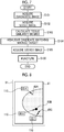
- the mammography apparatus 10 acquires the CC image 61 and/or the MLO image 71 as the diagnostic image by the diagnostic image acquisition unit 51 (step S101). For example, in a case where test subject information of the test subject undergoing the biopsy is set and registered in the mammography apparatus 10 or the like, the mammography apparatus 10 automatically performs this diagnostic image acquisition step before the biopsy.
- the diagnostic image acquisition step can be performed by an explicit operation input by the doctor or the like.
- the doctor or the radiation technician sets the mamma of the test subject undergoing the biopsy on the imaging stand 33, and inputs an instruction for execution of the scout imaging to the mammography apparatus 10.
- the scout image acquisition unit 52 acquires the scout image 81 (step S102).
- the tissue similarity degree calculation unit 55 recognizes the calcifications 85A to 85C in the scout image 81 and calculates the tissue similarity degree which is a similarity degree with the marked calcification 65B in the diagnostic image.
- the tissue similarity degree calculation unit 55 calculates the tissue similarity degree for each of the calcifications 85A to 85C in the scout image 81 (step S103).
- the display unit 56 determines whether each of the calcifications 85A to 85C matches the marked calcification 65B in the diagnostic image using the tissue similarity degree by the determination unit 59. Then, the display unit 56 highlights the calcification which matches the marked calcification 65B in the diagnostic image, based on the determination result of the determination unit 59 (step S104). In the present embodiment, as a result of the determination of the determination unit 59, each of the calcifications 85A to 85C in the scout image 81 matches the marked calcification 65B in the diagnostic image.
- the display unit 56 displays the positions of the calcifications 85A to 85C in the scout image 81, that is, the positions of candidates for the biological tissue examination.
- the display unit 56 indicates the position of each of the calcifications 85A to 85C using a leader line with an arrow from each of the calcifications 85A to 85C in the scout image 81, and indicates the specific value 110 of the tissue similarity degree of each of the calcifications 85A to 85C. In this manner, the display unit 56 displays the positions of the candidates for the biological tissue examination in the scout image 81 to overlap the scout image 81.
- the value 110 of the tissue similarity degree of the calcification 85A is "23.4" (%).
- the value 110 of the tissue similarity degree of the calcification 85B is "98.6” (%)
- the value 110 of the tissue similarity degree of the calcification 85C is "33.7” (%).
- the calcification 85B in the scout image 81 is the calcification which actually matches the calcification 65B (target of the biological tissue examination) in the CC image 61 marked during the diagnosis.
- the doctor checks the display of the scout image 81 or the like on the display unit 56, and then inputs an instruction for acquiring a stereo image to the mammography apparatus 10.
- the stereo image acquisition unit 53 acquires the stereo images 101 and 102 (step S105), and the stereo images 101 and 102 are displayed in the stereo image display area 92.
- the doctor punctures the mamma of the test subject using a biopsy needle or the Mammotome while referring to the display of the images (step S106), and performs the biopsy. More specifically, the doctor specifies the calcification 85B as the biopsy target by referring to the display of the position and/or the tissue similarity degree of the calcification in the scout image 81. Further, the doctor performs the biopsy while checking the three-dimensional position of the calcification 85B as the biopsy target by referring to the stereo images 101 and 102.
- the display unit 56 highlights at least a candidate for the biological tissue examination in the scout image 81 which matches the marked target of the biological tissue examination in the diagnostic image. Therefore, the doctor can easily and accurately capture the biopsy target specified in the diagnosis by the display of the scout image 81 and the highlighted candidates for the biological tissue examination.
- the mammography apparatus in the related art in which such display is not performed it has to specify the calcification as the biopsy target again using the scout image 81, and thus a calcification different from the calcification at the time of the diagnosis may incorrectly be collected in some cases. As compared with such a case, the mammography apparatus 10 can avoid an unnecessary or incorrect biopsy.
- the pain of the test subject is less as compared with the mammography apparatus in the related art. Further, since a situation in which the biopsy has to be performed again hardly occurs, at this point, the burden on the test subject can be reduced and the workflow of the biopsy can be improved.
- the mammography apparatus 10 determines whether the marked calcification 65B in the diagnostic image matches the calcifications 85A to 85C in the scout image 81 using the tissue similarity degree indicating the similarity degree as the tissue structure, and determines whether to highlight the calcifications 85A to 85C in the scout image 81 according to the determination result. That is, the candidates for the biological tissue examination to be highlighted on the display unit 56 are only calcifications having a high similarity degree as the tissue structure with the marked calcification 65B in the diagnostic image.
- the display by the highlighting becomes complicated, which disturbs the specifying as the biopsy target, in some cases.
- the highlighting on the display unit 56 since the highlighting on the display unit 56 selectively displays only the actual biopsy target or the candidate having a high possibility to be the biopsy target, and the display aspect is simple, it is easy to capture the biopsy target by the scout image 81 and the highlighting on the scout image 81.
- the mammography apparatus 10 can assist in capturing the biopsy target directly and accurately by displaying the tissue similarity degree.
- information is insufficient to identify the calcification as the target specified during the diagnosis simply by the fact that the position of the candidate (calcifications 85A to 85C in the embodiment) of the target in the biopsy image is similar to the position of the target specified during the diagnosis (in a case where the calcifications are dense or the like), it is possible to reduce the possibility of incorrectly recognizing an actual target with the near target candidates.
- the tissue similarity degree is displayed in combination with the position of the candidate (calcification 85B and the like) of the biological tissue examination in the scout image 81, which matches the marked target (calcification 65B) of the biological tissue examination in the diagnostic image, but the display of the tissue similarity degree can be omitted.
- the doctor or the like can distinguish the target of the biological tissue examination specified in the diagnostic image in a case where the position of one or a plurality of candidates for the biological tissue examination is displayed based on the tissue similarity degree, unless the calcifications are dense or the like.
- the arrows in Fig. 8 are left and the display of the value 110 of the tissue similarity degree (numerical values and parts surrounding the numerical values) is omitted.
- the display unit 56 highlights all of the calcifications 85A to 85C recognized by the tissue similarity degree calculation unit 55 as a result of the determination, but the display unit 56 can selectively display the tissue similarity degree for some of the calcifications 85A to 85C recognized by the tissue similarity degree calculation unit 55 by adjusting the value of the threshold that the determination unit 59 uses for determination.
- the threshold that the determination unit 59 uses for determination is "20", but in a case where the setting of the value is changed to, for example, "70", the display unit 56 can selectively highlight only the calcification 85B which actually matches the marked calcification 65B in the diagnostic image (or only the calcification having high similarity with the calcification 65B, in particular) as shown in Fig. 9 . That is, the display unit 56 can highlight only the actual biopsy target depending on the adjustment.
- specifying the calcification, which matches the calcification 65B marked during the diagnosis, in the scout image 81 is made easy by highlighting the candidates for the biological tissue examination in the scout image 81, but it is preferable to highlight the calcification which matches the calcification 65B marked during the diagnosis, in the stereo images 101 and 102 in addition to the highlighting of the candidates in the scout image 81 or instead of the highlighting in the scout image 81. For example, as shown in Fig.
- a marker 201 is attached to the calcification which matches "the marked calcification 65B (or the calcification in the scout image 81 which matches the marked calcification 65B)" among the calcifications shown in the stereo image 101 and/or the stereo image 102, and is highlighted. This is because it becomes easy to grasp the three-dimensional position of the calcification 85B as the biopsy target.
- the console 12 is provided with a stereo image recognition unit 210.
- the stereo image recognition unit 210 recognizes the calcifications in the stereo images 101 and 102, and associates the calcifications in the stereo images 101 and 102 with "the marked calcification 65B in the diagnostic image (or the calcification in the scout image 81 which matches the marked calcification 65B in the diagnostic image)".
- the display unit 56 highlights the calcification which matches the marked calcification 65B in the diagnostic image, among calcifications in the stereo images 101 and 102. In this manner, the biopsy target can be accurately displayed also in the stereo images 101 and 102. As a result, it is possible to assist in grasping the three-dimensional position of the biopsy target.
- the association process performed by the stereo image recognition unit 210 can be performed by calculating a second tissue similarity degree which is a similarity degree between the calcification in the stereo images 101 and 102 and the marked calcification 65B in the diagnostic image or the calcification 85B in the scout image 81 which matches the marked calcification 65B in the diagnostic image, for example.
- the display unit 56 highlights at least the calcification having the highest second tissue similarity degree, among the calcifications in the stereo images 101 and 102. In this manner, the biopsy target can be accurately displayed also in the stereo images 101 and 102.
- the display unit 56 may set a threshold for determining whether to perform highlighting, for the second tissue similarity degree.
- the candidates for the biological tissue examination in the stereo images 101 and 102 are highlighted, but in addition to the highlighting of the candidates for the biological tissue examination, the value of the second tissue similarity degree can be displayed in the stereo images 101 and 102.
- the value of the second tissue similarity degree is displayed, it is possible to assist in capturing the biopsy target directly and accurately. This is the same reason as the case in which the tissue similarity degree is displayed in the scout image 81.
- the stereo image acquisition unit 53 prohibits the capturing of the stereo images 101 and 102. This is because, even if the stereo images 101 and 102 are captured without correcting such a situation, a probability of obtaining stereo images 101 and 102 including the calcification as the biopsy target is low, and as a result, useless exposure is increased, which becomes a burden on the test subject.
- the mammography apparatus 10 assists in selecting the tomosynthesis image 106 to be displayed on the display unit 56.
- the console 12 is provided with a tomosynthesis image recognition unit 310.
- the tomosynthesis image recognition unit 310 recognizes the calcifications in a series of tomosynthesis images, and associates the calcification in each tomosynthesis image with the marked calcification 65B in the diagnostic image or the calcification in the scout image 81 which matches the marked calcification 65B in the diagnostic image.
- the display unit 56 selects and displays some tomosynthesis images from among a series of tomosynthesis images.
- the display unit 56 selects and displays one or a plurality of tomosynthesis images 106 including the calcification matching the marked calcification 65B in the diagnostic image, from among calcifications in a series of tomosynthesis images. In this manner, it is possible to assist in capturing the biopsy target by displaying the tomosynthesis image 106, in which the biopsy target is appropriately shown, in the limited tomosynthesis image display area 93.
- the association process performed by the tomosynthesis image recognition unit 310 can be performed by calculating a third tissue similarity degree which is a similarity degree between the calcification in the tomosynthesis image and the marked calcification 65B in the diagnostic image or the calcification in the scout image 81 which matches the marked calcification 65B in the diagnostic image, for example.
- the display unit 56 displays at least the tomosynthesis image 106 including the calcification having the highest third tissue similarity degree, among the calcifications in a series of tomosynthesis images. In this manner, it is possible to display an appropriate tomosynthesis image 106 including the biopsy target from among a series of tomosynthesis images.
- the display unit 56 may set a threshold for determining whether to perform highlighting, for the third tissue similarity degree.
- the third tissue similarity degree is used only for the selection of the tomosynthesis image 106, but the candidates for the biological tissue examination may be highlighted at least in the tomosynthesis image 106 selected for display. For example, similar to the first embodiment or the second embodiment, it is possible to highlight some or all of the recognized calcifications in the tomosynthesis image 106 using the third tissue similarity degree. In addition to the highlighting indicating the position or the like of the candidate for the biological tissue examination, the value of the third tissue similarity degree can be displayed in the tomosynthesis image 106. In a case where the value of the third tissue similarity degree is displayed, it is possible to assist in capturing the biopsy target directly and accurately.
- the highlighting in the tomosynthesis image 106 the highlighting for indicating the position of the candidate for the biological tissue examination in the scout image 81 and/or the stereo images 101 and 102 may be omitted. This is because the position of the calcification can be checked in the tomosynthesis image 106.
- the highlighting for indicating the position of the candidate for the biological tissue examination in the tomosynthesis image 106 is used in combination with the highlighting for indicating the position of the candidate for the biological tissue examination in the scout image 81 and/or the stereo images 101 and 102. This is for more accurately specifying the position of the candidate for the biological tissue examination.
- the tomosynthesis image acquisition unit 54 prohibits the imaging for obtaining the tomosynthesis image. This is because, even if the tomosynthesis imaging is performed without correcting such a situation, a probability of obtaining a tomosynthesis image including the calcification as the biopsy target is low, and as a result, useless exposure is increased, which becomes a burden on the test subject.
- whether the display unit 56 highlights the candidates for the biological tissue examination in the scout image 81 is determined using the determination result of the determination unit 59 based on the tissue similarity degree, but it is preferable that whether to highlight the candidates for the biological tissue examination in the scout image 81 is determined in consideration of the similarity between the diagnostic image (CC image 61 or MLO image 71) with the scout image 81 as the whole image.
- the console 12 is provided with an image similarity degree calculation unit 410.
- the image similarity degree calculation unit 410 calculates an image similarity degree as a similarity degree for a partial image or a whole image between the diagnostic image and the scout image 81. Then, whether the display unit 56 highlights the candidate for the biological tissue examination is determined using the image similarity degree. For example, the display unit 56 sets a predetermined threshold (hereinafter, referred to as a second threshold) for the image similarity degree.
- the display unit 56 highlights the candidate for the biological tissue examination in a case where the value 110 of the image similarity degree is equal to or greater than the second threshold. In doing so, in a case where there is a difference in the shape or the like of the image of the mamma such that the diagnostic image and the scout image 81 are not similar as a whole image (or the entire region of interest specified or the like), it is possible to prevent that the calcification which has high similarity of the shape or the like of the calcification (high tissue similarity degree) but actually is not a real target is displayed, and to improve the reliability for the display of the position of the candidate for the biological tissue examination.
- portion of the diagnostic image and the scout image 81 in the fourth embodiment does not mean a very small region (for example, a region close to actually a "point") such as a calcification, and is a portion having a size (area) enough to discriminate a shape or the like of the tissue of the mamma of the test subject in addition to the calcification as the biopsy target or the candidate thereof, for example, a region of interest having a size enough to include the entire image of one or a plurality of calcifications.
- the biopsy target is marked in the diagnostic image. Accordingly, in a case where there is no marked calcification 65B in the diagnostic image, it is preferable that the warning notification unit 57 notifies of a warning to prompt the marking of a calcification. This is for effectively utilizing the assistance in capturing the target by the mammography apparatus 10.
- a marking unit 501 is provided to the warning notification unit 57, and the doctor or the like may mark the biopsy target in the diagnostic image on the spot using the marking unit 501.
- the marking unit 501 is a so-called computer-aided diagnosis (CAD) program and there is no marked calcification in the diagnostic image
- the marking unit 501 provides a function of recognizing calcifications in the diagnostic image and marking some or all of the recognized calcifications.
- the scout image 81 is a biopsy image
- the scout image 81 is captured under an imaging condition different from that of the diagnostic image.
- a grid is not used.
- the scout image acquisition unit 52 can acquire a scout image of which at least one or a plurality conditions among use or non-use of a grid, a tube voltage of the X-ray tube (in case of using other radiation, a radiation tube generating the radiation), and a dose of the X-rays (radiation) are the same as the diagnostic image.
- the tissue similarity degree between the marked calcification 65B in the diagnostic image and the corresponding calcification 85B in the scout image 81 becomes high, and conversely, the tissue similarity degree between the marked calcification 65B with the other calcifications 85A and 85C in the scout image 81 becomes low. Accordingly, it is possible to highlight the calcification 85B as the biopsy target to be distinguished from the other calcifications 85A and 85C.
- the scout image acquisition unit 52 acquires a scout image 81 in which the grid is used, it is preferable to acquire a scout image 81 in which a grid having the same grid ratio as the grid used for capturing the diagnostic image is used. This is for specifying the calcification 85B as the biopsy target with particularly high accuracy.
- the scout image acquisition unit 52 can acquire a scout image 81 subjected to the image processing, it is preferable that the scout image acquisition unit 52 acquires a scout image 81 subjected to the same image processing as the diagnostic image. This is for distinguishing the calcification 85B, which is the biopsy target, more accurately from the other calcifications 85A and 85C.
- parameters such as the imaging condition (tube voltage or the like) at the time of capturing the diagnostic image and the type, strength, or the like of the image processing performed at the time of acquiring the diagnostic image are attached to the diagnostic image or preserved in association with the diagnostic image, for example. Therefore, the scout image acquisition unit 52 can acquire information directly from the diagnostic image and indirectly via the diagnostic image acquisition unit 51.
- the tissue similarity degree calculation unit 55 can recognize calcifications in the scout image 81 by so-called pattern matching and calculate the tissue similarity degree.
- the stereo image recognition unit 210 and the tomosynthesis image recognition unit 310 can recognize the calcifications by the pattern matching.
- the tissue similarity degree calculation unit 55 can use a "learned model” (so-called artificial intelligence (AI) program) which outputs a probability that the calcification in the scout image 81 is the marked calcification 65B in the diagnostic image by inputting the diagnostic image in which the calcification 65B as the biopsy target is marked and the scout image 81 to specify the position of the calcification and output the "probability" that the learned model outputs as the tissue similarity degree.
- AI artificial intelligence
- the tissue similarity degree calculation unit 55 can be configured by the AI program which causes an arithmetic operation device (combination of CPU, GPU, and/or a memory) of the mammography apparatus 10 or an arithmetic operation device cooperating with the mammography apparatus 10 to calculate the tissue similarity degree using the learned model which outputs the positions of the calcifications 85A to 85C in the scout image 81 and the tissue similarity degree as the similarity degree between the calcifications 85A to 85C in the scout image 81 and the marked calcification 65B in the diagnostic image by inputting the diagnostic image and the scout image 81 (biopsy image).
- the AI program causes an arithmetic operation device (combination of CPU, GPU, and/or a memory) of the mammography apparatus 10 or an arithmetic operation device cooperating with the mammography apparatus 10 to calculate the tissue similarity degree using the learned model which outputs the positions of the calcifications 85A to 85C in the scout image
- the pattern matching or the learned model can be used for the recognition processing or the like in the stereo image recognition unit 210, the tomosynthesis image recognition unit 310, and/or the image similarity degree calculation unit 410. It is possible to configure each of units by using the AI program in which learned models having the functions of the units are used.
- the mammography apparatus 10 is described as an example, but the present invention can be preferably used in a radiographic apparatus or an ultrasonic inspection apparatus that can perform the biological tissue examination.
- These apparatuses can be configured using the diagnostic image acquisition unit that acquires a diagnostic image in which a target of the biological tissue examination is marked, the image acquisition unit that acquires a biopsy image in which the subject undergoing the biological tissue examination is shown in a case where the biological tissue examination is performed, and the display unit that highlights the candidates for the biological tissue examination in the biopsy image matching at least the marked target of the biological tissue examination in the diagnostic image.
- the hardware structures of the processing unit executing various processing such as the tissue similarity degree calculation unit 55, the determination unit 59, the stereo image recognition unit 210, the tomosynthesis image recognition unit 310, and the image similarity degree calculation unit 410 are various processors described below.
- the various processors include a central processing unit (CPU) and a graphical processing unit (GPU) as a general-purpose processor executing software (program) and functioning as various processing units, a programmable logic device (PLD) as a processor of which the circuit configuration can be changed after manufacturing such as a field programmable gate array (FPGA), a dedicated electrical circuit as a processor having a circuit configuration designed exclusively for executing various processing, and the like.
- CPU central processing unit
- GPU graphical processing unit
- PLD programmable logic device
- FPGA field programmable gate array
- FPGA field programmable gate array
- One processing unit may be configured by one of the various processors, or configured by the combination of the same or different kinds of two or more processors (for example, combination of a plurality of FPGAs, combination of the CPU and the FPGA, combination of the CPU and the GPU, or the like). Further, a plurality of processing units may be configured by one processor. As an example where a plurality of processing units are configured by one processor, first, there is an aspect where one processor is configured by a combination of one or more CPUs and software as typified by a computer, such as a client or a server, and this processor functions as a plurality of processing units.
- a processor fulfilling the functions of the entire system including a plurality of processing units by one integrated circuit (IC) chip as typified by a system on a chip (SoC) or the like is used.
- IC integrated circuit
- SoC system on a chip
- the hardware structures of the various processors are more specifically electrical circuitry in a form in which circuit elements, such as semiconductor elements, are combined.
Landscapes
- Engineering & Computer Science (AREA)
- Health & Medical Sciences (AREA)
- Life Sciences & Earth Sciences (AREA)
- Medical Informatics (AREA)
- Physics & Mathematics (AREA)
- General Health & Medical Sciences (AREA)
- Nuclear Medicine, Radiotherapy & Molecular Imaging (AREA)
- Radiology & Medical Imaging (AREA)
- Theoretical Computer Science (AREA)
- Biomedical Technology (AREA)
- Optics & Photonics (AREA)
- Pathology (AREA)
- High Energy & Nuclear Physics (AREA)
- Heart & Thoracic Surgery (AREA)
- Molecular Biology (AREA)
- Surgery (AREA)
- Animal Behavior & Ethology (AREA)
- Biophysics (AREA)
- Public Health (AREA)
- Veterinary Medicine (AREA)
- Computer Vision & Pattern Recognition (AREA)
- General Physics & Mathematics (AREA)
- Multimedia (AREA)
- Evolutionary Computation (AREA)
- Artificial Intelligence (AREA)
- Dentistry (AREA)
- Quality & Reliability (AREA)
- Oral & Maxillofacial Surgery (AREA)
- Software Systems (AREA)
- Databases & Information Systems (AREA)
- Computing Systems (AREA)
- Data Mining & Analysis (AREA)
- Human Computer Interaction (AREA)
- Physiology (AREA)
- Bioinformatics & Cheminformatics (AREA)
- Bioinformatics & Computational Biology (AREA)
- Evolutionary Biology (AREA)
- General Engineering & Computer Science (AREA)
- Apparatus For Radiation Diagnosis (AREA)
Abstract
Description
- The present invention relates to a mammography apparatus for imaging a mamma of a test subject using radiation such as X-rays, and a program for driving the mammography apparatus.
- In the related art, the mammography apparatus is used for breast cancer screening, a biological tissue examination (hereinafter, referred to as a biopsy), and the like. Since the breast cancer is closely associated with a calcification, in the breast cancer screening, it is common to search for a calcification using an image captured by using the mammography apparatus (hereinafter, referred to as a mammography image) and to diagnose whether the found a calcification is associated with the breast cancer. Then, in a case where a calcification that may be associated with the breast cancer is found, a biopsy is performed. The biopsy is for a definitive diagnosis.
- Meanwhile, a method of positioning two images for medical use is known (
JP2013-501290A - In a case where a biopsy is performed, a biopsy target specified using an image used for diagnosis (hereinafter, referred to as a diagnostic image) has to be searched for again using an image captured in case of performing a biopsy (hereinafter, referred to as a biopsy image), but there was no auxiliary means to find the target, which is specified using the diagnostic image, in the biopsy image. Therefore, during the biopsy, an incorrect target (target different from the target specified using the diagnostic image) may be collected, which becomes a burden on a test subject.
- An object of the invention is to specify a candidate for a target in a biopsy image using a diagnostic image in a case where a biopsy is performed.
- A mammography apparatus according to an aspect of the invention comprises a diagnostic image acquisition unit that acquires a diagnostic image which is a mammography image used for diagnosis and in which a target of a biological tissue examination is marked; a scout image acquisition unit that acquires a scout image obtained by imaging a mamma undergoing the biological tissue examination from a specific direction; and a display unit that highlights a candidate for the biological tissue examination in the scout image which matches at least the marked target in the diagnostic image.
- It is preferable that a tissue similarity degree calculation unit recognizes the "candidate" in the scout image and calculates a tissue similarity degree which is a similarity degree between the "candidate" in the scout image and the marked target in the diagnostic image, and a determination unit determines whether the candidate matches the target using the tissue similarity degree.
- It is preferable that the display unit displays a value of the tissue similarity degree.
- It is preferable that the display unit highlights the "candidate" of which the tissue similarity degree is equal to or greater than a first threshold.
- It is preferable that the mammography apparatus includes an image similarity degree calculation unit that calculates an image similarity degree which is a similarity degree for a partial image or a whole image between the diagnostic image and the scout image, and the display unit determines whether to highlight the "candidate" using the image similarity degree.
- It is preferable that the display unit highlights the "candidate" in a case where the image similarity degree is equal to or greater than a second threshold.
- It is preferable that the mammography apparatus includes a warning notification unit that notifies of a warning at least in a case where there is no candidate to be highlighted by the display unit.
- It is preferable that the warning notification unit prompts recapturing of the scout image.
- It is preferable that the display unit displays a position of the "candidate" in the scout image which matches the marked target in the diagnostic image, by highlighting.
- It is preferable that the mammography apparatus includes a stereo image acquisition unit that acquires a stereo image obtained by imaging the mamma undergoing the biological tissue examination from an inclination direction which is inclined with respect to the specific direction from which the scout image is captured; and a stereo image recognition unit that recognizes the "candidate" in the stereo image, and associates the "candidate" in the stereo image with the marked target in the diagnostic image or the "candidate" in the scout image which matches the marked target in the diagnostic image, and the display unit highlights the candidate matching the marked target in the diagnostic image among the candidates in the stereo image.
- It is preferable that the stereo image recognition unit calculates a second tissue similarity degree which is a similarity degree between the "candidate" in the stereo image and the marked target in the diagnostic image or the "candidate" in the scout image which matches the marked target in the diagnostic image, and the display unit highlights at least the "candidate" having the highest second tissue similarity degree among the "candidates" in the stereo image.
- It is preferable that the stereo image acquisition unit prohibits capturing of the stereo image in a case where there is no "candidate" in the scout image, which matches the marked target in the diagnostic image.
- It is preferable that the mammography apparatus includes a tomosynthesis image acquisition unit that acquires a series of tomosynthesis images of the mamma undergoing the biological tissue examination; and a tomosynthesis image recognition unit that recognizes the target of the biological tissue examination in the series of tomosynthesis images, and associates the candidate in each tomosynthesis image with the marked target in the diagnostic image or the candidate in the scout image which matches the marked target in the diagnostic image, and the display unit selects and displays some of the tomosynthesis images from among the series of tomosynthesis images using a recognition result of the tomosynthesis image recognition unit.
- It is preferable that the tomosynthesis image recognition unit calculates a third tissue similarity degree which is a similarity degree between the "candidate" in the tomosynthesis image and the marked target in the diagnostic image or the "candidate" in the scout image which matches the marked target in the diagnostic image, and the display unit displays the tomosynthesis image including at least a calcification having the highest third tissue similarity degree among the "candidates" in the series of tomosynthesis images.
- It is preferable that the tomosynthesis image acquisition unit prohibits imaging for obtaining the tomosynthesis image in a case where there is no "candidate" in the scout image, which matches the marked target in the diagnostic image.
- It is preferable that the mammography apparatus includes a warning notification unit that notifies of a warning to prompt marking of the calcification in a case where there is no marked target in the diagnostic image.
- It is preferable that the mammography apparatus includes a marking unit that recognizes the "candidates" in the diagnostic image and marks some or all of the recognized "candidates" in a case where there is no marked target in the diagnostic image.
- It is preferable that the scout image acquisition unit acquires the scout image of which at least one or a plurality conditions among use or non-use of a grid, a tube voltage of a radiation tube, and a dose of radiation are the same as the diagnostic image.
- It is preferable that the scout image acquisition unit acquires the scout image in which a grid having the same grid ratio as a grid used for capturing the diagnostic image is used in a case where the scout image in which the grid is used is acquired.
- It is preferable that the scout image acquisition unit acquires the scout image subjected to the same image processing as the diagnostic image.
- It is preferable that the tissue similarity degree calculation unit recognizes the "candidate" in the scout image by pattern matching and calculates the tissue similarity degree.
- It is preferable that the tissue similarity degree calculation unit outputs a probability that the candidate for the biological tissue examination in the scout image is the marked target in the diagnostic image, as the tissue similarity degree by using a learned model that outputs the probability by inputting the diagnostic image in which the target of the biological tissue examination is marked and the scout image.
- A program according to an aspect of the invention is a program driving a mammography apparatus including a display unit that highlights a candidate for a biological tissue examination in a biopsy image captured in the biological tissue examination, and the program causes an arithmetic operation device of the mammography apparatus or an arithmetic operation device cooperating with the mammography apparatus to calculate the tissue similarity degree used for determining the "candidate" to be highlighted by the display unit, by using a learned model that outputs a position of the "candidate" in the biopsy image and a tissue similarity degree which is a similarity degree between the "candidate" in the biopsy image and a marked target in the diagnostic image by inputting the biopsy image and the diagnostic image in which the target of the biological tissue examination is marked.
- According to the invention, it is possible to specify a candidate for a target in a biopsy image using a diagnostic image in a case where a biopsy is performed.
-
-
Fig. 1 is an explanatory diagram showing a configuration of a mammography apparatus. -
Fig. 2 is a block diagram showing a configuration of a console. -
Fig. 3 is a CC image to be used for diagnosis. -
Fig. 4 is an MLO image to be used for diagnosis. -
Fig. 5 is an example of a scout image which is one of biopsy images. -
Fig. 6 is an explanatory diagram showing a display example of biopsy images on a display unit. -
Fig. 7 is a flowchart showing an operation of a mammography apparatus in case of performing a biopsy. -
Fig. 8 is a display example of a tissue similarity degree. -
Fig. 9 is another display example of a tissue similarity degree. -
Fig. 10 is a display example showing a position of a target in a stereo image which is one of biopsy images. -
Fig. 11 is a block diagram showing a configuration of a console according to a second embodiment. -
Fig. 12 is a block diagram showing a configuration of a console according to a third embodiment. -
Fig. 13 is a block diagram showing a configuration of a console according to a fourth embodiment. -
Fig. 14 is a block diagram showing a configuration of a console of a modification example. - As shown in
Fig. 1 , amammography apparatus 10 includes anapparatus body 11 which images a mamma of a test subject using X-rays, and aconsole 12 which controls theapparatus body 11. - The
apparatus body 11 includes aprop 31, anX-ray generation part 32, an imaging stand 33 with a built-in X-ray imaging part, apressing plate 36, a lifting/loweringpart 37, and the like. In addition, theX-ray generation part 32 and theimaging stand 33 are integrated and configure amovable part 40 which adjusts a position according to a test subject in theapparatus body 11. - The
imaging stand 33 is a stage on which a mamma of a test subject is placed, and clamps the mamma of the test subject using thepressing plate 36 during imaging. The X-ray imaging part (not shown) built in theimaging stand 33 includes a flat panel detector (FPD) or the like which images a subject using, for example, radiation, and a grid for removing scattered rays (stationary Lysholm blende or mobile bucky blende). Themammography apparatus 10 has multiple types of grids which are replaceable according to the imaging conditions, and can perform imaging in which the grid is not used. In addition, agrip part 34a that the test subject grips with the right hand and agrip part 34b that the test subject grips with the left hand are attached to the imaging stand 33. Thegrip part 34a and thegrip part 34b are a so-called arm rest. - The
pressing plate 36 presses the mamma of the test subject, which is placed on theimaging stand 33, and makes the mamma flat. This is to reduce the overlap of normal mammary glands and make it easier to find a candidate for a lesion such as a calcification. The lifting/loweringpart 37 lifts or lowers thepressing plate 36 with respect to theimaging stand 33. In this manner, the lifting/loweringpart 37 supports thepressing plate 36 approximately parallel to theimaging stand 33 and at a specific distance according to the thickness of the mamma. - The
movable part 40 is rotatable within a predetermined angle range while maintaining the relative position and direction of theX-ray generation part 32 and theimaging stand 33. Therefore, theapparatus body 11 can perform imaging with the imaging stand 33 being disposed horizontally or the imaging stand 33 being disposed obliquely with respect to the horizontal. Specifically, theapparatus body 11 can perform craniocaudal imaging (CC imaging) in which a mamma is imaged from a craniocaudal direction, with the imaging stand 33 being disposed horizontally. In addition, theapparatus body 11 can perform mediolateral oblique imaging (MLO imaging) in which a mamma is imaged from a mediolateral oblique direction, with the imaging stand 33 being disposed obliquely. - Further, the
X-ray generation part 32 of themovable part 40 is rotatable within a predetermined range while the positions of theimaging stand 33 and thepressing plate 36 are fixed. In this manner, theapparatus body 11 can perform so-called stereo imaging and tomosynthesis imaging. The stereo imaging is an imaging aspect in which the mamma of the test subject fixed at specific position and direction (for example, position and direction of the CC imaging) is imaged from one or a plurality of inclination directions with different inclination angles and a fluoroscopic image from the inclination direction (hereinafter, referred to as a stereo image) is obtained. In addition, the tomosynthesis imaging is an imaging aspect in which a tomographic image (hereinafter, referred to as a tomosynthesis image) of a mamma of a test subject is obtained using images of the mamma of the test subject fixed at the specific position and direction, which are captured from a plurality of inclination directions. - As shown in
Fig. 2 , theconsole 12 includes a diagnosticimage acquisition unit 51, a scoutimage acquisition unit 52, a stereoimage acquisition unit 53, a tomosynthesisimage acquisition unit 54, a tissue similaritydegree calculation unit 55, adisplay unit 56, and awarning notification unit 57. - The diagnostic
image acquisition unit 51 acquires diagnostic images from a radiology information system (RIS), a picture archiving and communication system (PACS), a hospital information system (HIS), or the like which is directly or indirectly connected to themammography apparatus 10. The diagnostic image is a mammography image used for diagnosis, and a mammography image in which a target of the biological tissue examination is marked is obtained. The target of the biological tissue examination is simply a biopsy target, for example, a calcification. Hereinafter, in this specification, it is assumed that the target of the biological tissue examination is a "calcification" and the target of the biological tissue examination is simply referred to as a calcification. Note that, for a lesion or a portion that could be a lesion, regardless of a specific form of the tissue or structure thereof, a tissue or the like other than calcifications can be a target of the biological tissue examination. - Usually, CC imaging and MLO imaging are performed for diagnosis, and thus the diagnostic images acquired by the diagnostic
image acquisition unit 51 are CC images and MLO images in which a calcification as the biopsy target is marked. The marking for a calcification means that information specifying the position of a calcification as the biopsy target is attached to a partial or entire diagnostic image. For example, attaching a marker, a label, or the like to a specific calcification in the diagnostic image to specify the position of the calcification and/or recording information such as coordinates indicating the position or the range of a specific calcification in association with the diagnostic image corresponds to the marking for a calcification. In the present embodiment, for the calcification as the biopsy target, a doctor attaches a specific marker to the diagnostic image, and the coordinates of the position of the marker are recorded in the header or the like of the diagnostic image. - As shown in
Fig. 3 , aCC image 61 as one of the diagnostic images is composed of aleft mamma image 62 obtained by imaging the left mamma of the test subject from the CC direction, and aright mamma image 63 obtained by imaging the right mamma of the test subject from the CC direction. In the present embodiment, there are a plurality ofcalcifications 65A to 65C in theleft mamma image 62. In addition, it is assumed that the doctor diagnoses that a biopsy is necessary for thecalcification 65B among thecalcifications 65A to 65C and marks thecalcification 65B by attaching amarker 66, for example. - In addition, as shown in
Fig. 4 , anMLO image 71 as one of the diagnostic images is composed of aleft mamma image 72 obtained by imaging the left mamma of the test subject from an inclination direction inclined by a predetermined angle (hereinafter, referred to as an MLO direction), and aright mamma image 73 obtained by imaging the right mamma of the test subject from the MLO direction. In the present embodiment, in theMLO image 71, there are a plurality ofcalcifications 75A to 75C in theleft mamma image 72. Then, among the plurality ofcalcifications 75A to 75C in theMLO image 71, thecalcification 75A corresponds to thecalcification 65A in theCC image 61, thecalcification 75B corresponds to thecalcification 65B in theCC image 61, and thecalcification 75C corresponds to thecalcification 65C in theCC image 61. In addition, in the diagnosis, the doctor marks thecalcification 75B by attaching amarker 76 to thecalcification 75B of theMLO image 71. - The scout
image acquisition unit 52 acquires a scout image obtained by imaging the mamma undergoing the biological tissue examination from a specific direction. More specifically, in case of performing a biopsy, the scoutimage acquisition unit 52 controls theX-ray generation part 32 and the X-ray imaging part included in the imaging stand 33 to image the mamma of the test subject undergoing the biopsy, and thereby acquires a scout image 81 (refer toFig. 5 ) as one of the biopsy images. Thescout image 81 is a mammography image captured in order to search for a calcification as a biopsy target in case of performing a biopsy. In the present embodiment, as shown inFig. 5 , thescout image 81 is an image obtained by imaging the left mamma of the test subject from the CC direction, and a plurality ofcalcifications 85A to 85C are shown. These calcifications are candidates for the biological tissue examination. In general, the grid is not used in the capturing of a so-called scout image, and thus thescout image 81 acquired in the present embodiment is captured without using the grid. Note that, themammography apparatus 10 can use a grid for capturing a scout image as necessary. - In case of performing a biopsy, the stereo
image acquisition unit 53 acquires a stereo image obtained by imaging the mamma undergoing the biopsy, from an inclination direction which is inclined with respect to the specific direction from which thescout image 81 is captured. More specifically, the stereoimage acquisition unit 53 controls theX-ray generation part 32 and the X-ray imaging part included in the imaging stand 33 to image the mamma from one or a plurality of inclination directions, and thereby acquires one or a plurality of stereo images. Since the stereo image is captured in case of performing a biopsy, the stereo image is the biopsy image. The stereo image is used in combination with the scout image in order to specify a three-dimensional position of the calcification (three-dimensional position within the mamma) as the biopsy target. In the present embodiment, the stereoimage acquisition unit 53 images the mamma of the test subject from two inclination directions. Therefore, the stereoimage acquisition unit 53 acquires astereo image 101 and a stereo image 102 (refer toFig. 6 ). The calcifications shown in thestereo image 101 and/or thestereo image 102 are candidates for the biological tissue examination. - The tomosynthesis
image acquisition unit 54 acquires a series of tomosynthesis images of a mamma undergoing the biopsy. More specifically, in case of performing a biopsy, the tomosynthesisimage acquisition unit 54 images the mamma of the test subject undergoing the biopsy a plurality of times while moving theX-ray generation part 32. Then, for the mamma of the test subject undergoing the biopsy, a series of tomosynthesis images consisting of one or a plurality of tomographic images is acquired using the obtained images. The acquisition of the tomosynthesis images by the tomosynthesisimage acquisition unit 54 is performed as necessary. The calcification shown in the tomosynthesis image is a candidate for the biological tissue examination. - The tissue similarity
degree calculation unit 55 recognizes a calcification in thescout image 81 and calculates a tissue similarity degree. The tissue similarity degree is a similarity degree between the calcification (candidate for the biological tissue examination) in thescout image 81 and themarked calcification 65B (target of the biological tissue examination) in the diagnostic image. In the present embodiment, the tissue similaritydegree calculation unit 55 recognizes each of the threecalcifications 85A to 85C in thescout image 81. Then, the tissue similaritydegree calculation unit 55 calculates a tissue similarity degree between each of thecalcifications 85A to 85C in thescout image 81 and themarked calcification 65B in theCC image 61 as one of the diagnostic images. That is, the tissue similaritydegree calculation unit 55 calculates a tissue similarity degree between thecalcification 85A and thecalcification 65B, a tissue similarity degree between thecalcification 85B and thecalcification 65B, and a tissue similarity degree between thecalcification 85C and thecalcification 65B. As the value of the tissue similarity degree becomes larger, the similarity with themarked calcification 65B is high and the possibility that the calcification is the same as themarked calcification 65B is high. - The
display unit 56 is configured of a display such as a liquid display device or the like and a control circuit thereof (display control unit), for example. Thedisplay unit 56 highlights at least "a candidate for the biological tissue examination in thescout image 81 which matches the marked target of the biological tissue examination in the diagnostic image". The "highlighting" for the candidate for the biological tissue examination refers to a display aspect in which the position, size, range, shape, or the like of one or a plurality of candidates for the biological tissue examination can be distinguished from other tissues or the like, and includes a display aspect in which the candidate for the biological tissue examination can be distinguished from other tissues by directly changing the display aspect of the candidate for the biological tissue examination, and a display aspect in which the candidate for the biological tissue examination can be indirectly distinguished from other tissues by changing the display aspect of other tissues or the like. For example, thedisplay unit 56 can highlight the candidate for the biological tissue examination by using a method of surrounding the candidate for the biological tissue examination with a circle, an ellipse, a quadrangle, or the like, attaching a marker, a sign, or a symbol such as "○", "◊", or an arrow to the candidate for the biological tissue examination, displaying the candidate in association with a numerical value, a character, or the like, or changing a color, a density, or brightness of the candidate for the biological tissue examination or the other tissues. - The
display unit 56 includes adetermination unit 59. In the present embodiment, thedetermination unit 59 is one of the functions of the display control circuit configuring thedisplay unit 56. However, thedetermination unit 59 can be provided separately from thedisplay unit 56 and the display control circuit configuring thedisplay unit 56. That is, thedetermination unit 59 may not be provided to be included in thedisplay unit 56. Thedetermination unit 59 determines whether themarked calcification 65B (target of the biological tissue examination) in the diagnostic image matches thecalcifications 85A to 85C (candidates for the biological tissue examination) in thescout image 81. Thedisplay unit 56 decides the candidate for the biological tissue examination to be highlighted among thecalcifications 85A to 85C in thescout image 81 by using the determination result of thedetermination unit 59. That is, thedisplay unit 56 highlights the candidate for the biological tissue examination of which the tissue similarity degree is equal to or greater than a threshold (first threshold). - The
determination unit 59 uses the tissue similarity degrees for the determination. Specifically, thedetermination unit 59 compares a predetermined threshold (first threshold) with the tissue similarity degree, and determines that the calcification (candidate for the biological tissue examination) having a tissue similarity degree equal to or greater than the threshold "matches" themarked calcification 65B (target of the biological tissue examination) in the diagnostic image. Conversely, thedetermination unit 59 determines that the calcification (candidate for the biological tissue examination) having a value of the tissue similarity degree less than the threshold "does not match" the marked calcification (target of the biological tissue examination) in the diagnostic image. That is, in the comparison between the marked target of the biological tissue examination in the diagnostic image and the candidate for the biological tissue examination in the biopsy image, the term "matching" refers to having a similarity equal to or greater than a certain level. Particularly, in the comparison between themarked calcification 65B (target of the biological tissue examination) in the diagnostic image and thecalcifications 85A to 85C (candidate for the biological tissue examination) in thescout image 81, the term "matching" refers to having a tissue similarity degree equal to or greater than the predetermined threshold (first threshold). - The setting of the threshold that the
determination unit 59 uses for determination can be arbitrarily changed according to the specific properties of the target of the biological tissue examination, for example. In addition, even in a case where there is onemarked calcification 65B in the diagnostic image, thedisplay unit 56 may highlight a plurality of calcifications, and in the plurality of calcifications, thecalcification 85B (candidate for the biological tissue examination) actually matching themarked calcification 65B in the diagnostic image is included. The expression "actually matching" refers to actually the same or corresponding tissue or structure, or the like. - In the present embodiment, the tissue similarity degree is a nonnegative real number, and the threshold that the
determination unit 59 uses for determination is, for example, "20". Therefore, in the determination of thedetermination unit 59 for determining at least the necessity of the highlighting, the calcification of which the tissue similarity degree is equal to or greater than "20" is treated to match themarked calcification 65B in the diagnostic image, and becomes the target to be highlighted by thedisplay unit 56. As a result, thedisplay unit 56 highlights the candidate (calcification 85B) of the biological tissue examination in thescout image 81 which is one of the candidates for the biological tissue examination recognized by the tissue similaritydegree calculation unit 55 and matches the marked target (calcification 65B) of the biological tissue examination in the diagnostic image. In the present embodiment, thedisplay unit 56 highlights the candidates for the biological tissue examination in thescout image 81 by attaching arrows to the candidates (calcifications 85A to 85C) of the biological tissue examination to indicate the positions thereof and displaying thevalue 110 of the tissue similarity degree. - More specifically, the
display unit 56 displays the position of the calcification (candidate for the biological tissue examination) in thescout image 81 which matches the marked calcification (target of the biological tissue examination) in the diagnostic image, by using the tissue similarity degree. Further, thedisplay unit 56 displays the tissue similarity degree and the position of the calcification in thescout image 81 in an association manner. For example, as shown inFig. 6 , thedisplay unit 56 has a scoutimage display area 91 where thescout image 81 is displayed, a stereoimage display area 92 where the stereo image is displayed, and a tomosynthesisimage display area 93 where the tomosynthesis image is displayed. Thedisplay unit 56 displays the tissue similarity degrees at the positions of thecalcifications 85A to 85C in an association manner, for example, in the scoutimage display area 91. "Displaying" the tissue similarity degree includes an aspect in which thevalue 110 or the magnitude of the tissue similarity degree can be recognized in addition to directly displaying thevalue 110 of the tissue similarity degree (refer toFig. 8 ). For example, a color according to thevalue 110 of the tissue similarity degree is attached to thecalcifications 85A to 85C, or a marker having a color, a shape, or a size according to thevalue 110 of the tissue similarity degree is attached to thecalcifications 85A to 85C. That is, displaying the tissue similarity degree is one aspect of highlighting the candidates for the biological tissue examination indicated by the "probability" that the candidate for the biopsy target is the target. - In the stereo
image display area 92, for example, thestereo image 101 obtained by imaging the mamma of the test subject undergoing the biopsy from a first inclination direction, and thestereo image 102 obtained by imaging the mamma of the test subject undergoing the biopsy from an inclination direction different from the first inclination direction are displayed. In addition, in the tomosynthesisimage display area 93, in a case where a series of tomosynthesis images is acquired for the mamma of the test subject undergoing the biopsy, one or a plurality of tomosynthesis images are selected and displayed. InFig. 6 , in the tomosynthesisimage display area 93, selected onetomosynthesis image 106 is displayed. Thetomosynthesis image 106 displayed in the tomosynthesisimage display area 93 can be switched to another tomosynthesis image (another tomographic image among the series of tomosynthesis images). - The
warning notification unit 57 notifies of a warning at least in a case where there is no calcification (candidate for the biological tissue examination) to be highlighted by thedisplay unit 56. The case where there is no calcification to be highlighted by thedisplay unit 56 is, for example, a case in which the tissue similaritydegree calculation unit 55 is not able to recognize any one of thecalcifications 85A to 85C in thescout image 81 and thus is not able to calculate the tissue similarity degree, a case in which there is no calcification having the tissue similarity degree equal to or greater than the predetermined threshold, and the like. Thewarning notification unit 57 notifies of a warning to prompt the recapturing of thescout image 81, for example. That there is no calcification of which the position is displayed on thedisplay unit 56 can be caused by the fact that thescout image 81 is not appropriately captured. In a case where the biopsy is performed without correcting such a situation, the calcification as the biopsy target cannot be specified, and as a result, an accurate biopsy cannot be performed, which becomes a burden on the test subject. Thewarning notification unit 57 notifies of the warning using a message by a sound or display on thedisplay unit 56, turning on or off of an indicator (including an indicator displayed on the display unit 56), or generating other sounds, light, or the like. - Hereinafter, an operation aspect of the
mammography apparatus 10 configured as described above, in particular, an operation aspect of themammography apparatus 10 in case of performing the biopsy is described. First, as a premise, a doctor or a radiation technician acquires theCC image 61 and theMLO image 71 which are the diagnostic images, for the mamma of the test subject using themammography apparatus 10. Then, the doctor makes a diagnosis using theCC image 61 and theMLO image 71. In a case where the calcification that may be associated with the breast cancer is found in theCC image 61 and theMLO image 71, the doctor decides to perform a biopsy for the test subject. In this case, the doctor marks one or a plurality of calcifications as the biopsy target in theCC image 61 and/or theMLO image 71, and preserves the images in the PACS (more specifically, a digital imaging and communications in medicine (DICOM) server configuring the PACS), for example. - Thereafter, in case of performing the biopsy, as shown in
Fig. 7 , themammography apparatus 10 acquires theCC image 61 and/or theMLO image 71 as the diagnostic image by the diagnostic image acquisition unit 51 (step S101). For example, in a case where test subject information of the test subject undergoing the biopsy is set and registered in themammography apparatus 10 or the like, themammography apparatus 10 automatically performs this diagnostic image acquisition step before the biopsy. Of course, the diagnostic image acquisition step can be performed by an explicit operation input by the doctor or the like. - Meanwhile, the doctor or the radiation technician sets the mamma of the test subject undergoing the biopsy on the
imaging stand 33, and inputs an instruction for execution of the scout imaging to themammography apparatus 10. In this manner, the scoutimage acquisition unit 52 acquires the scout image 81 (step S102). In a case where the scoutimage acquisition unit 52 acquires thescout image 81, the tissue similaritydegree calculation unit 55 recognizes thecalcifications 85A to 85C in thescout image 81 and calculates the tissue similarity degree which is a similarity degree with themarked calcification 65B in the diagnostic image. In this manner, the tissue similaritydegree calculation unit 55 calculates the tissue similarity degree for each of thecalcifications 85A to 85C in the scout image 81 (step S103). - In a case where the tissue similarity
degree calculation unit 55 calculates the tissue similarity degree, thedisplay unit 56 determines whether each of thecalcifications 85A to 85C matches themarked calcification 65B in the diagnostic image using the tissue similarity degree by thedetermination unit 59. Then, thedisplay unit 56 highlights the calcification which matches themarked calcification 65B in the diagnostic image, based on the determination result of the determination unit 59 (step S104). In the present embodiment, as a result of the determination of thedetermination unit 59, each of thecalcifications 85A to 85C in thescout image 81 matches themarked calcification 65B in the diagnostic image. Therefore, thedisplay unit 56 displays the positions of thecalcifications 85A to 85C in thescout image 81, that is, the positions of candidates for the biological tissue examination. For example, as shown inFig. 8 , thedisplay unit 56 indicates the position of each of thecalcifications 85A to 85C using a leader line with an arrow from each of thecalcifications 85A to 85C in thescout image 81, and indicates thespecific value 110 of the tissue similarity degree of each of thecalcifications 85A to 85C. In this manner, thedisplay unit 56 displays the positions of the candidates for the biological tissue examination in thescout image 81 to overlap thescout image 81. InFig. 8 , thevalue 110 of the tissue similarity degree of thecalcification 85A is "23.4" (%). Similarly, thevalue 110 of the tissue similarity degree of thecalcification 85B is "98.6" (%), and thevalue 110 of the tissue similarity degree of thecalcification 85C is "33.7" (%). Accordingly, thecalcification 85B in thescout image 81 is the calcification which actually matches thecalcification 65B (target of the biological tissue examination) in theCC image 61 marked during the diagnosis. - Thereafter, the doctor checks the display of the
scout image 81 or the like on thedisplay unit 56, and then inputs an instruction for acquiring a stereo image to themammography apparatus 10. In this manner, the stereoimage acquisition unit 53 acquires thestereo images 101 and 102 (step S105), and thestereo images image display area 92. - The doctor punctures the mamma of the test subject using a biopsy needle or the Mammotome while referring to the display of the images (step S106), and performs the biopsy. More specifically, the doctor specifies the
calcification 85B as the biopsy target by referring to the display of the position and/or the tissue similarity degree of the calcification in thescout image 81. Further, the doctor performs the biopsy while checking the three-dimensional position of thecalcification 85B as the biopsy target by referring to thestereo images - As described above, in the
mammography apparatus 10, thedisplay unit 56 highlights at least a candidate for the biological tissue examination in thescout image 81 which matches the marked target of the biological tissue examination in the diagnostic image. Therefore, the doctor can easily and accurately capture the biopsy target specified in the diagnosis by the display of thescout image 81 and the highlighted candidates for the biological tissue examination. In the mammography apparatus in the related art in which such display is not performed, it has to specify the calcification as the biopsy target again using thescout image 81, and thus a calcification different from the calcification at the time of the diagnosis may incorrectly be collected in some cases. As compared with such a case, themammography apparatus 10 can avoid an unnecessary or incorrect biopsy. As a result, the pain of the test subject is less as compared with the mammography apparatus in the related art. Further, since a situation in which the biopsy has to be performed again hardly occurs, at this point, the burden on the test subject can be reduced and the workflow of the biopsy can be improved. - The
mammography apparatus 10 determines whether themarked calcification 65B in the diagnostic image matches thecalcifications 85A to 85C in thescout image 81 using the tissue similarity degree indicating the similarity degree as the tissue structure, and determines whether to highlight thecalcifications 85A to 85C in thescout image 81 according to the determination result. That is, the candidates for the biological tissue examination to be highlighted on thedisplay unit 56 are only calcifications having a high similarity degree as the tissue structure with themarked calcification 65B in the diagnostic image. For example, in a case where all of the calcifications which can be recognized are highlighted without being subjected to the determination, if the number of calcifications is large, the display by the highlighting becomes complicated, which disturbs the specifying as the biopsy target, in some cases. In contrast, in themammography apparatus 10, since the highlighting on thedisplay unit 56 selectively displays only the actual biopsy target or the candidate having a high possibility to be the biopsy target, and the display aspect is simple, it is easy to capture the biopsy target by thescout image 81 and the highlighting on thescout image 81. - The
mammography apparatus 10 can assist in capturing the biopsy target directly and accurately by displaying the tissue similarity degree. In a case where information is insufficient to identify the calcification as the target specified during the diagnosis simply by the fact that the position of the candidate (calcifications 85A to 85C in the embodiment) of the target in the biopsy image is similar to the position of the target specified during the diagnosis (in a case where the calcifications are dense or the like), it is possible to reduce the possibility of incorrectly recognizing an actual target with the near target candidates. - In the first embodiment, the tissue similarity degree is displayed in combination with the position of the candidate (
calcification 85B and the like) of the biological tissue examination in thescout image 81, which matches the marked target (calcification 65B) of the biological tissue examination in the diagnostic image, but the display of the tissue similarity degree can be omitted. This is because the doctor or the like can distinguish the target of the biological tissue examination specified in the diagnostic image in a case where the position of one or a plurality of candidates for the biological tissue examination is displayed based on the tissue similarity degree, unless the calcifications are dense or the like. For example, there is a display aspect in which the arrows inFig. 8 are left and the display of thevalue 110 of the tissue similarity degree (numerical values and parts surrounding the numerical values) is omitted. - In the first embodiment, the
display unit 56 highlights all of thecalcifications 85A to 85C recognized by the tissue similaritydegree calculation unit 55 as a result of the determination, but thedisplay unit 56 can selectively display the tissue similarity degree for some of thecalcifications 85A to 85C recognized by the tissue similaritydegree calculation unit 55 by adjusting the value of the threshold that thedetermination unit 59 uses for determination. In the first embodiment, the threshold that thedetermination unit 59 uses for determination is "20", but in a case where the setting of the value is changed to, for example, "70", thedisplay unit 56 can selectively highlight only thecalcification 85B which actually matches themarked calcification 65B in the diagnostic image (or only the calcification having high similarity with thecalcification 65B, in particular) as shown inFig. 9 . That is, thedisplay unit 56 can highlight only the actual biopsy target depending on the adjustment. - In the first embodiment, specifying the calcification, which matches the
calcification 65B marked during the diagnosis, in thescout image 81 is made easy by highlighting the candidates for the biological tissue examination in thescout image 81, but it is preferable to highlight the calcification which matches thecalcification 65B marked during the diagnosis, in thestereo images scout image 81 or instead of the highlighting in thescout image 81. For example, as shown inFig. 10 , amarker 201 is attached to the calcification which matches "themarked calcification 65B (or the calcification in thescout image 81 which matches themarked calcification 65B)" among the calcifications shown in thestereo image 101 and/or thestereo image 102, and is highlighted. This is because it becomes easy to grasp the three-dimensional position of thecalcification 85B as the biopsy target. - In this case, as shown in
Fig. 11 , theconsole 12 is provided with a stereoimage recognition unit 210. The stereoimage recognition unit 210 recognizes the calcifications in thestereo images stereo images marked calcification 65B in the diagnostic image (or the calcification in thescout image 81 which matches themarked calcification 65B in the diagnostic image)". Using a result of this association, thedisplay unit 56 highlights the calcification which matches themarked calcification 65B in the diagnostic image, among calcifications in thestereo images stereo images - The association process performed by the stereo
image recognition unit 210 can be performed by calculating a second tissue similarity degree which is a similarity degree between the calcification in thestereo images marked calcification 65B in the diagnostic image or thecalcification 85B in thescout image 81 which matches themarked calcification 65B in the diagnostic image, for example. In this case, thedisplay unit 56 highlights at least the calcification having the highest second tissue similarity degree, among the calcifications in thestereo images stereo images display unit 56 may set a threshold for determining whether to perform highlighting, for the second tissue similarity degree. - In the second embodiment, the candidates for the biological tissue examination in the
stereo images stereo images scout image 81. - In the first and second embodiments, in a case where there is no calcification, which matches the
marked calcification 65B in the diagnostic image, in thescout image 81, it is preferable that the stereoimage acquisition unit 53 prohibits the capturing of thestereo images stereo images stereo images - In the first and second embodiments, in case of performing the tomosynthesis imaging, since the tomosynthesis
image display area 93 is limited, one or a plurality of tomosynthesis images (in the embodiments, one tomosynthesis image 106) are selectively displayed from among a series of tomosynthesis images consisting of a plurality of tomosynthesis images. However, it is not easy to select a tomosynthesis image in which the biopsy target is appropriately shown from among a series of tomosynthesis images. Therefore, in case of performing the tomosynthesis imaging, it is preferable that themammography apparatus 10 assists in selecting thetomosynthesis image 106 to be displayed on thedisplay unit 56. - In this case, as shown in
Fig. 12 , theconsole 12 is provided with a tomosynthesisimage recognition unit 310. The tomosynthesisimage recognition unit 310 recognizes the calcifications in a series of tomosynthesis images, and associates the calcification in each tomosynthesis image with themarked calcification 65B in the diagnostic image or the calcification in thescout image 81 which matches themarked calcification 65B in the diagnostic image. Using a result of the recognition and the association (recognition result of the tomosynthesis image recognition unit 310), thedisplay unit 56 selects and displays some tomosynthesis images from among a series of tomosynthesis images. That is, in the present embodiment, thedisplay unit 56 selects and displays one or a plurality oftomosynthesis images 106 including the calcification matching themarked calcification 65B in the diagnostic image, from among calcifications in a series of tomosynthesis images. In this manner, it is possible to assist in capturing the biopsy target by displaying thetomosynthesis image 106, in which the biopsy target is appropriately shown, in the limited tomosynthesisimage display area 93. - The association process performed by the tomosynthesis
image recognition unit 310 can be performed by calculating a third tissue similarity degree which is a similarity degree between the calcification in the tomosynthesis image and themarked calcification 65B in the diagnostic image or the calcification in thescout image 81 which matches themarked calcification 65B in the diagnostic image, for example. In this case, thedisplay unit 56 displays at least thetomosynthesis image 106 including the calcification having the highest third tissue similarity degree, among the calcifications in a series of tomosynthesis images. In this manner, it is possible to display anappropriate tomosynthesis image 106 including the biopsy target from among a series of tomosynthesis images. Of course, thedisplay unit 56 may set a threshold for determining whether to perform highlighting, for the third tissue similarity degree. - In the third embodiment, the third tissue similarity degree is used only for the selection of the
tomosynthesis image 106, but the candidates for the biological tissue examination may be highlighted at least in thetomosynthesis image 106 selected for display. For example, similar to the first embodiment or the second embodiment, it is possible to highlight some or all of the recognized calcifications in thetomosynthesis image 106 using the third tissue similarity degree. In addition to the highlighting indicating the position or the like of the candidate for the biological tissue examination, the value of the third tissue similarity degree can be displayed in thetomosynthesis image 106. In a case where the value of the third tissue similarity degree is displayed, it is possible to assist in capturing the biopsy target directly and accurately. This is because it is possible to easily check that the candidate for the biological tissue examination of which the position is indicated is similar to the biopsy target specified in the diagnostic image. In a case where the position of the candidate for the biological tissue examination is indicated by the highlighting in thetomosynthesis image 106, the highlighting for indicating the position of the candidate for the biological tissue examination in thescout image 81 and/or thestereo images tomosynthesis image 106. Note that, it is preferable that the highlighting for indicating the position of the candidate for the biological tissue examination in thetomosynthesis image 106 is used in combination with the highlighting for indicating the position of the candidate for the biological tissue examination in thescout image 81 and/or thestereo images - In the first, second, and third embodiments, in a case where there is no calcification, which matches the
marked calcification 65B in the diagnostic image, in thescout image 81, it is preferable that the tomosynthesisimage acquisition unit 54 prohibits the imaging for obtaining the tomosynthesis image. This is because, even if the tomosynthesis imaging is performed without correcting such a situation, a probability of obtaining a tomosynthesis image including the calcification as the biopsy target is low, and as a result, useless exposure is increased, which becomes a burden on the test subject. - In the first, second, and third embodiments, whether the
display unit 56 highlights the candidates for the biological tissue examination in thescout image 81 is determined using the determination result of thedetermination unit 59 based on the tissue similarity degree, but it is preferable that whether to highlight the candidates for the biological tissue examination in thescout image 81 is determined in consideration of the similarity between the diagnostic image (CC image 61 or MLO image 71) with thescout image 81 as the whole image. This is because, in a case where the image of the mamma of the subject shown in the diagnostic image is not similar to that shown in thescout image 81 as the whole image, even if the similarity in a limited region such as a calcification portion (vicinity of the candidates for the biological tissue examination) is high, the possibility that the calcification does not actually match the marked calcification (target of the biological tissue examination) in the diagnostic image is high. - In a case where whether to highlight the candidates for the biological tissue examination is determined in consideration of the similarity between the diagnostic image and the
scout image 81 as the whole image, as shown inFig. 13 , theconsole 12 is provided with an image similaritydegree calculation unit 410. The image similaritydegree calculation unit 410 calculates an image similarity degree as a similarity degree for a partial image or a whole image between the diagnostic image and thescout image 81. Then, whether thedisplay unit 56 highlights the candidate for the biological tissue examination is determined using the image similarity degree. For example, thedisplay unit 56 sets a predetermined threshold (hereinafter, referred to as a second threshold) for the image similarity degree. Thedisplay unit 56 highlights the candidate for the biological tissue examination in a case where thevalue 110 of the image similarity degree is equal to or greater than the second threshold. In doing so, in a case where there is a difference in the shape or the like of the image of the mamma such that the diagnostic image and thescout image 81 are not similar as a whole image (or the entire region of interest specified or the like), it is possible to prevent that the calcification which has high similarity of the shape or the like of the calcification (high tissue similarity degree) but actually is not a real target is displayed, and to improve the reliability for the display of the position of the candidate for the biological tissue examination. - The term "portion" of the diagnostic image and the
scout image 81 in the fourth embodiment does not mean a very small region (for example, a region close to actually a "point") such as a calcification, and is a portion having a size (area) enough to discriminate a shape or the like of the tissue of the mamma of the test subject in addition to the calcification as the biopsy target or the candidate thereof, for example, a region of interest having a size enough to include the entire image of one or a plurality of calcifications. - In the above-described embodiments and the modification example, it is assumed that the biopsy target is marked in the diagnostic image. Accordingly, in a case where there is no
marked calcification 65B in the diagnostic image, it is preferable that thewarning notification unit 57 notifies of a warning to prompt the marking of a calcification. This is for effectively utilizing the assistance in capturing the target by themammography apparatus 10. As shown inFig. 14 , for example, a markingunit 501 is provided to thewarning notification unit 57, and the doctor or the like may mark the biopsy target in the diagnostic image on the spot using themarking unit 501. In a case where the markingunit 501 is a so-called computer-aided diagnosis (CAD) program and there is no marked calcification in the diagnostic image, the markingunit 501 provides a function of recognizing calcifications in the diagnostic image and marking some or all of the recognized calcifications. - In the above-described embodiments and the modification example, since the
scout image 81 is a biopsy image, thescout image 81 is captured under an imaging condition different from that of the diagnostic image. For example, a grid is not used. However, the scoutimage acquisition unit 52 can acquire a scout image of which at least one or a plurality conditions among use or non-use of a grid, a tube voltage of the X-ray tube (in case of using other radiation, a radiation tube generating the radiation), and a dose of the X-rays (radiation) are the same as the diagnostic image. In this manner, in a case where the scoutimage acquisition unit 52 acquires ascout image 81 captured under the same imaging condition as that of the diagnostic image, the tissue similarity degree between themarked calcification 65B in the diagnostic image and thecorresponding calcification 85B in thescout image 81 becomes high, and conversely, the tissue similarity degree between themarked calcification 65B with theother calcifications scout image 81 becomes low. Accordingly, it is possible to highlight thecalcification 85B as the biopsy target to be distinguished from theother calcifications - In particular, in a case where the scout
image acquisition unit 52 acquires ascout image 81 in which the grid is used, it is preferable to acquire ascout image 81 in which a grid having the same grid ratio as the grid used for capturing the diagnostic image is used. This is for specifying thecalcification 85B as the biopsy target with particularly high accuracy. - In addition, in a case where the scout
image acquisition unit 52 can acquire ascout image 81 subjected to the image processing, it is preferable that the scoutimage acquisition unit 52 acquires ascout image 81 subjected to the same image processing as the diagnostic image. This is for distinguishing thecalcification 85B, which is the biopsy target, more accurately from theother calcifications - In the above described modification example, parameters such as the imaging condition (tube voltage or the like) at the time of capturing the diagnostic image and the type, strength, or the like of the image processing performed at the time of acquiring the diagnostic image are attached to the diagnostic image or preserved in association with the diagnostic image, for example. Therefore, the scout
image acquisition unit 52 can acquire information directly from the diagnostic image and indirectly via the diagnosticimage acquisition unit 51. - In the embodiments and the modification example, the tissue similarity
degree calculation unit 55 can recognize calcifications in thescout image 81 by so-called pattern matching and calculate the tissue similarity degree. Similarly, the stereoimage recognition unit 210 and the tomosynthesisimage recognition unit 310 can recognize the calcifications by the pattern matching. - Instead of the pattern matching, the tissue similarity
degree calculation unit 55 can use a "learned model" (so-called artificial intelligence (AI) program) which outputs a probability that the calcification in thescout image 81 is themarked calcification 65B in the diagnostic image by inputting the diagnostic image in which thecalcification 65B as the biopsy target is marked and thescout image 81 to specify the position of the calcification and output the "probability" that the learned model outputs as the tissue similarity degree. In addition, the tissue similaritydegree calculation unit 55 can be configured by the AI program which causes an arithmetic operation device (combination of CPU, GPU, and/or a memory) of themammography apparatus 10 or an arithmetic operation device cooperating with themammography apparatus 10 to calculate the tissue similarity degree using the learned model which outputs the positions of thecalcifications 85A to 85C in thescout image 81 and the tissue similarity degree as the similarity degree between thecalcifications 85A to 85C in thescout image 81 and themarked calcification 65B in the diagnostic image by inputting the diagnostic image and the scout image 81 (biopsy image). Similarly, the pattern matching or the learned model can be used for the recognition processing or the like in the stereoimage recognition unit 210, the tomosynthesisimage recognition unit 310, and/or the image similaritydegree calculation unit 410. It is possible to configure each of units by using the AI program in which learned models having the functions of the units are used. - In the above-described embodiments or the like, the
mammography apparatus 10 is described as an example, but the present invention can be preferably used in a radiographic apparatus or an ultrasonic inspection apparatus that can perform the biological tissue examination. These apparatuses can be configured using the diagnostic image acquisition unit that acquires a diagnostic image in which a target of the biological tissue examination is marked, the image acquisition unit that acquires a biopsy image in which the subject undergoing the biological tissue examination is shown in a case where the biological tissue examination is performed, and the display unit that highlights the candidates for the biological tissue examination in the biopsy image matching at least the marked target of the biological tissue examination in the diagnostic image. - In the above-described embodiments, the hardware structures of the processing unit executing various processing such as the tissue similarity
degree calculation unit 55, thedetermination unit 59, the stereoimage recognition unit 210, the tomosynthesisimage recognition unit 310, and the image similaritydegree calculation unit 410 are various processors described below. The various processors include a central processing unit (CPU) and a graphical processing unit (GPU) as a general-purpose processor executing software (program) and functioning as various processing units, a programmable logic device (PLD) as a processor of which the circuit configuration can be changed after manufacturing such as a field programmable gate array (FPGA), a dedicated electrical circuit as a processor having a circuit configuration designed exclusively for executing various processing, and the like. - One processing unit may be configured by one of the various processors, or configured by the combination of the same or different kinds of two or more processors (for example, combination of a plurality of FPGAs, combination of the CPU and the FPGA, combination of the CPU and the GPU, or the like). Further, a plurality of processing units may be configured by one processor. As an example where a plurality of processing units are configured by one processor, first, there is an aspect where one processor is configured by a combination of one or more CPUs and software as typified by a computer, such as a client or a server, and this processor functions as a plurality of processing units. Second, there is an aspect where a processor fulfilling the functions of the entire system including a plurality of processing units by one integrated circuit (IC) chip as typified by a system on a chip (SoC) or the like is used. In this way, various processing units are configured using one or more of the above-described various processors as hardware structures.
- Furthermore, the hardware structures of the various processors are more specifically electrical circuitry in a form in which circuit elements, such as semiconductor elements, are combined.
-
- 10:
- mammography apparatus
- 11:
- apparatus body
- 12:
- console
- 31:
- prop
- 32:
- X-ray generation part
- 33:
- imaging stand
- 34a:
- grip part
- 34b:
- grip part
- 36:
- pressing plate
- 37:
- lifting/lowering part
- 40:
- movable part
- 51:
- diagnostic image acquisition unit
- 52:
- scout image acquisition unit
- 53:
- stereo image acquisition unit
- 54:
- tomosynthesis image acquisition unit
- 55:
- tissue similarity degree calculation unit
- 56:
- display unit
- 57:
- warning notification unit
- 59:
- determination unit
- 61:
- CC image
- 62:
- left mamma image
- 63:
- right mamma image
- 65A to 65C:
- calcification
- 66:
- marker
- 71:
- MLO image
- 72:
- left mamma image
- 73:
- right mamma image
- 75A to 75C:
- calcification
- 76:
- marker
- 81:
- scout image
- 85A to 85C:
- calcification
- 91:
- scout image display area
- 92:
- stereo image display area
- 93:
- tomosynthesis image display area
- 101, 102:
- stereo image
- 106:
- tomosynthesis image
- 110:
- value of tissue similarity degree
- 201:
- marker
- 210:
- stereo image recognition unit
- 310:
- tomosynthesis image recognition unit
- 410:
- image similarity degree calculation unit
- 501:
- marking unit
- S101 to S106:
- operation step
Claims (23)
- A mammography apparatus comprising:a diagnostic image acquisition unit that acquires a diagnostic image which is a mammography image used for diagnosis and in which a target of a biological tissue examination is marked;a scout image acquisition unit that acquires a scout image obtained by imaging a mamma undergoing the biological tissue examination from a specific direction; anda display unit that highlights a candidate for the biological tissue examination in the scout image which matches at least the marked target in the diagnostic image.
- The mammography apparatus according to claim 1, further comprising:a tissue similarity degree calculation unit that recognizes the candidate for the biological tissue examination in the scout image and calculates a tissue similarity degree which is a similarity degree between the candidate in the scout image and the marked target in the diagnostic image; anda determination unit that determines whether the candidate matches the target using the tissue similarity degree.
- The mammography apparatus according to claim 2,
wherein the display unit displays a value of the tissue similarity degree. - The mammography apparatus according to claim 2 or 3,
wherein the display unit highlights the candidate of which the tissue similarity degree is equal to or greater than a first threshold. - The mammography apparatus according to any one of claims 1 to 4, further comprising:an image similarity degree calculation unit that calculates an image similarity degree which is a similarity degree for a partial image or a whole image between the diagnostic image and the scout image,wherein the display unit determines whether to highlight the candidate using the image similarity degree.
- The mammography apparatus according to claim 5,
wherein the display unit highlights the candidate in a case where the image similarity degree is equal to or greater than a second threshold. - The mammography apparatus according to any one of claims 1 to 6, further comprising:
a warning notification unit that notifies of a warning at least in a case where there is no candidate to be highlighted by the display unit. - The mammography apparatus according to claim 7,
wherein the warning notification unit prompts recapturing of the scout image. - The mammography apparatus according to any one of claims 1 to 8,
wherein the display unit displays a position of the candidate in the scout image which matches the marked target in the diagnostic image, by highlighting. - The mammography apparatus according to any one of claims 1 to 9, further comprising:a stereo image acquisition unit that acquires a stereo image obtained by imaging the mamma undergoing the biological tissue examination from an inclination direction which is inclined with respect to the specific direction from which the scout image is captured; anda stereo image recognition unit that recognizes the candidate in the stereo image, and associates the candidate in the stereo image with the marked target in the diagnostic image or the candidate in the scout image which matches the marked target in the diagnostic image,wherein the display unit highlights the candidate matching the marked target in the diagnostic image among the candidates in the stereo image.
- The mammography apparatus according to claim 10,wherein the stereo image recognition unit calculates a second tissue similarity degree which is a similarity degree between the candidate in the stereo image and the marked target in the diagnostic image or the candidate in the scout image which matches the marked target in the diagnostic image, andthe display unit highlights at least the candidate having a highest second tissue similarity degree among the candidates in the stereo image.
- The mammography apparatus according to claim 10 or 11,
wherein the stereo image acquisition unit prohibits capturing of the stereo image in a case where there is no candidate in the scout image, which matches the marked target in the diagnostic image. - The mammography apparatus according to any one of claims 1 to 12, further comprising:a tomosynthesis image acquisition unit that acquires a series of tomosynthesis images of the mamma undergoing the biological tissue examination; anda tomosynthesis image recognition unit that recognizes the target of the biological tissue examination in the series of tomosynthesis images, and associates the candidate in each tomosynthesis image with the marked target in the diagnostic image or the candidate in the scout image which matches the marked target in the diagnostic image,wherein the display unit selects and displays some of the tomosynthesis images from among the series of tomosynthesis images using a recognition result of the tomosynthesis image recognition unit.
- The mammography apparatus according to claim 13,wherein the tomosynthesis image recognition unit calculates a third tissue similarity degree which is a similarity degree between the candidate in the tomosynthesis image and the marked target in the diagnostic image or the candidate in the scout image which matches the marked target in the diagnostic image, andthe display unit displays the tomosynthesis image including at least a calcification having a highest third tissue similarity degree among calcifications in the series of tomosynthesis images.
- The mammography apparatus according to claim 13 or 14,
wherein the tomosynthesis image acquisition unit prohibits imaging for obtaining the tomosynthesis image in a case where there is no candidate in the scout image, which matches the marked target in the diagnostic image. - The mammography apparatus according to any one of claims 1 to 15, further comprising:
a warning notification unit that notifies of a warning to prompt marking of the target in a case where there is no marked target in the diagnostic image. - The mammography apparatus according to any one of claims 1 to 16, further comprising:
a marking unit that recognizes the candidates in the diagnostic image and marks some or all of the recognized candidates in a case where there is no marked target in the diagnostic image. - The mammography apparatus according to any one of claims 1 to 17,
wherein the scout image acquisition unit acquires the scout image of which at least one or a plurality conditions among use or non-use of a grid, a tube voltage of a radiation tube, and a dose of radiation are the same as the diagnostic image. - The mammography apparatus according to claim 18,
wherein the scout image acquisition unit acquires the scout image in which a grid having the same grid ratio as a grid used for capturing the diagnostic image is used in a case where the scout image in which the grid is used is acquired. - The mammography apparatus according to any one of claims 1 to 19,
wherein the scout image acquisition unit acquires the scout image subjected to the same image processing as the diagnostic image. - The mammography apparatus according to claim 2,
wherein the tissue similarity degree calculation unit recognizes the candidate in the scout image by pattern matching and calculates the tissue similarity degree. - The mammography apparatus according to claim 2,
wherein the tissue similarity degree calculation unit outputs a probability that the candidate in the scout image is the marked target in the diagnostic image, as the tissue similarity degree by using a learned model that outputs the probability by inputting the diagnostic image in which the target is marked and the scout image. - A program driving a mammography apparatus including a display unit that highlights a candidate for a biological tissue examination in a biopsy image captured in the biological tissue examination, the program causing an arithmetic operation device of the mammography apparatus or an arithmetic operation device cooperating with the mammography apparatus to calculate a tissue similarity degree used for determining the candidate to be highlighted by the display unit, by using a learned model that outputs a position of the candidate in the biopsy image and the tissue similarity degree which is a similarity degree between the candidate in the biopsy image and a marked target in the diagnostic image by inputting the biopsy image and the diagnostic image in which the target of the biological tissue examination is marked.
Applications Claiming Priority (1)
| Application Number | Priority Date | Filing Date | Title |
|---|---|---|---|
| JP2019027982A JP7203474B2 (en) | 2019-02-20 | 2019-02-20 | Mammography device and program |
Publications (3)
| Publication Number | Publication Date |
|---|---|
| EP3698719A1 true EP3698719A1 (en) | 2020-08-26 |
| EP3698719B1 EP3698719B1 (en) | 2021-03-03 |
| EP3698719B8 EP3698719B8 (en) | 2021-04-21 |
Family
ID=69468503
Family Applications (1)
| Application Number | Title | Priority Date | Filing Date |
|---|---|---|---|
| EP20155500.0A Active EP3698719B8 (en) | 2019-02-20 | 2020-02-04 | Mammography apparatus and program |
Country Status (3)
| Country | Link |
|---|---|
| US (1) | US11559273B2 (en) |
| EP (1) | EP3698719B8 (en) |
| JP (1) | JP7203474B2 (en) |
Cited By (1)
| Publication number | Priority date | Publication date | Assignee | Title |
|---|---|---|---|---|
| EP4335377A1 (en) * | 2022-09-07 | 2024-03-13 | GE Precision Healthcare LLC | Methods and systems for digital mammography imaging |
Families Citing this family (4)
| Publication number | Priority date | Publication date | Assignee | Title |
|---|---|---|---|---|
| US11288883B2 (en) * | 2019-07-23 | 2022-03-29 | Toyota Research Institute, Inc. | Autonomous task performance based on visual embeddings |
| TWI799705B (en) * | 2020-05-20 | 2023-04-21 | 倍利科技股份有限公司 | Medical image aided interpretation system |
| JP7617816B2 (en) | 2021-06-18 | 2025-01-20 | 東京エレクトロン株式会社 | Plasma Processing Equipment |
| US11819355B2 (en) * | 2021-07-14 | 2023-11-21 | GE Precision Healthcare LLC | Methods and systems for automatic implant detection in mammography |
Citations (5)
| Publication number | Priority date | Publication date | Assignee | Title |
|---|---|---|---|---|
| US20020172414A1 (en) * | 2001-04-30 | 2002-11-21 | Serge Muller | Method and apparatus for locating elements of interest in a member |
| JP2013501290A (en) | 2009-08-07 | 2013-01-10 | ユーシーエル ビジネス ピーエルシー | Apparatus and method for aligning two medical images |
| DE102011080682A1 (en) * | 2011-08-09 | 2013-02-14 | Siemens Aktiengesellschaft | Method for controlling digital stereotactic biopsy using mammography device, involves capturing overview image of object area for biopsy, where two stereotactic images are captured, which comprises two images from different directions |
| US20170337336A1 (en) * | 2016-05-19 | 2017-11-23 | Siemens Healthcare Gmbh | Method and device for monitoring a breast examination |
| US20180078231A1 (en) * | 2016-09-20 | 2018-03-22 | KUB Technologies, Inc. | System and method for computer aided detection (cad) in a breast specimen radiograph |
Family Cites Families (8)
| Publication number | Priority date | Publication date | Assignee | Title |
|---|---|---|---|---|
| US6785410B2 (en) | 1999-08-09 | 2004-08-31 | Wake Forest University Health Sciences | Image reporting method and system |
| JP5628092B2 (en) | 2011-05-25 | 2014-11-19 | 富士フイルム株式会社 | Image processing apparatus, radiation image capturing system, image processing program, and operation method of image processing apparatus |
| EP4278977A3 (en) | 2013-10-24 | 2024-02-21 | Hologic, Inc. | System and method for navigating x-ray guided breast biopsy |
| US9474497B2 (en) * | 2014-01-15 | 2016-10-25 | Agfa Healthcare | Method and system for generating pre-scaled images for a series of mammography images |
| US10535167B2 (en) * | 2014-12-31 | 2020-01-14 | General Electric Company | Method and system for tomosynthesis projection image enhancement and review |
| CN107405126B (en) * | 2015-03-10 | 2022-01-25 | 皇家飞利浦有限公司 | Retrieving corresponding structures of pairs of medical images |
| US10925562B2 (en) * | 2017-02-22 | 2021-02-23 | General Electric Company | Variable SID imaging |
| EP3449830B1 (en) * | 2017-08-31 | 2020-01-29 | Siemens Healthcare GmbH | Control of a medical imaging device |
-
2019
- 2019-02-20 JP JP2019027982A patent/JP7203474B2/en active Active
-
2020
- 2020-02-04 EP EP20155500.0A patent/EP3698719B8/en active Active
- 2020-02-18 US US16/794,154 patent/US11559273B2/en active Active
Patent Citations (5)
| Publication number | Priority date | Publication date | Assignee | Title |
|---|---|---|---|---|
| US20020172414A1 (en) * | 2001-04-30 | 2002-11-21 | Serge Muller | Method and apparatus for locating elements of interest in a member |
| JP2013501290A (en) | 2009-08-07 | 2013-01-10 | ユーシーエル ビジネス ピーエルシー | Apparatus and method for aligning two medical images |
| DE102011080682A1 (en) * | 2011-08-09 | 2013-02-14 | Siemens Aktiengesellschaft | Method for controlling digital stereotactic biopsy using mammography device, involves capturing overview image of object area for biopsy, where two stereotactic images are captured, which comprises two images from different directions |
| US20170337336A1 (en) * | 2016-05-19 | 2017-11-23 | Siemens Healthcare Gmbh | Method and device for monitoring a breast examination |
| US20180078231A1 (en) * | 2016-09-20 | 2018-03-22 | KUB Technologies, Inc. | System and method for computer aided detection (cad) in a breast specimen radiograph |
Cited By (1)
| Publication number | Priority date | Publication date | Assignee | Title |
|---|---|---|---|---|
| EP4335377A1 (en) * | 2022-09-07 | 2024-03-13 | GE Precision Healthcare LLC | Methods and systems for digital mammography imaging |
Also Published As
| Publication number | Publication date |
|---|---|
| JP2020130603A (en) | 2020-08-31 |
| EP3698719B8 (en) | 2021-04-21 |
| US20200261046A1 (en) | 2020-08-20 |
| JP7203474B2 (en) | 2023-01-13 |
| EP3698719B1 (en) | 2021-03-03 |
| US11559273B2 (en) | 2023-01-24 |
Similar Documents
| Publication | Publication Date | Title |
|---|---|---|
| EP3698719B1 (en) | Mammography apparatus and program | |
| JP6331922B2 (en) | Medical image system and program | |
| JP5145169B2 (en) | Medical image photographing support apparatus and program | |
| JP7023254B2 (en) | Shooting support equipment, methods and programs | |
| CN104349721B (en) | Image processing apparatus | |
| US10916010B2 (en) | Learning data creation support apparatus, learning data creation support method, and learning data creation support program | |
| EP3825910B1 (en) | Method and apparatus of intelligent analysis for liver tumour | |
| CN102389319A (en) | Radiation image processing apparatus, radiation image processing method, and radiation image processing program | |
| US20210153838A1 (en) | Method and Apparatus of Intelligent Analysis for Liver Tumor | |
| JP2006116313A (en) | Diagnostic method in 3D imaging | |
| JP6455235B2 (en) | Medical image system and program | |
| US20170323447A1 (en) | Medical image capturing apparatus and method | |
| JP6832880B2 (en) | Learning data creation support device, learning data creation support method, and learning data creation support program | |
| EP2878266A1 (en) | Medical imaging system and program | |
| US20210097688A1 (en) | Display control device, method for operating display control device, and program for operating display control device | |
| US12245878B2 (en) | Radiography system, method for operating radiography system, and console for radiography system | |
| CN104809331A (en) | Method and system for detecting radiation images to find focus based on computer-aided diagnosis (CAD) | |
| JP2016195655A (en) | Medical image system and program | |
| JP2020130339A (en) | Information processing unit and program | |
| JP7290766B2 (en) | Information processing device and program | |
| US12579649B2 (en) | Radiation image processing apparatus and operation method thereof | |
| EP4119057A1 (en) | Methods and systems for automatic implant detection in mammography | |
| JP6953974B2 (en) | Diagnostic imaging system | |
| CN119587050A (en) | Calibration method and device for medical imaging equipment and medical imaging equipment |
Legal Events
| Date | Code | Title | Description |
|---|---|---|---|
| PUAI | Public reference made under article 153(3) epc to a published international application that has entered the european phase |
Free format text: ORIGINAL CODE: 0009012 |
|
| STAA | Information on the status of an ep patent application or granted ep patent |
Free format text: STATUS: THE APPLICATION HAS BEEN PUBLISHED |
|
| AK | Designated contracting states |
Kind code of ref document: A1 Designated state(s): AL AT BE BG CH CY CZ DE DK EE ES FI FR GB GR HR HU IE IS IT LI LT LU LV MC MK MT NL NO PL PT RO RS SE SI SK SM TR |
|
| AX | Request for extension of the european patent |
Extension state: BA ME |
|
| STAA | Information on the status of an ep patent application or granted ep patent |
Free format text: STATUS: REQUEST FOR EXAMINATION WAS MADE |
|
| 17P | Request for examination filed |
Effective date: 20201005 |
|
| RBV | Designated contracting states (corrected) |
Designated state(s): AL AT BE BG CH CY CZ DE DK EE ES FI FR GB GR HR HU IE IS IT LI LT LU LV MC MK MT NL NO PL PT RO RS SE SI SK SM TR |
|
| GRAP | Despatch of communication of intention to grant a patent |
Free format text: ORIGINAL CODE: EPIDOSNIGR1 |
|
| STAA | Information on the status of an ep patent application or granted ep patent |
Free format text: STATUS: GRANT OF PATENT IS INTENDED |
|
| INTG | Intention to grant announced |
Effective date: 20201211 |
|
| GRAS | Grant fee paid |
Free format text: ORIGINAL CODE: EPIDOSNIGR3 |
|
| GRAA | (expected) grant |
Free format text: ORIGINAL CODE: 0009210 |
|
| STAA | Information on the status of an ep patent application or granted ep patent |
Free format text: STATUS: THE PATENT HAS BEEN GRANTED |
|
| AK | Designated contracting states |
Kind code of ref document: B1 Designated state(s): AL AT BE BG CH CY CZ DE DK EE ES FI FR GB GR HR HU IE IS IT LI LT LU LV MC MK MT NL NO PL PT RO RS SE SI SK SM TR |
|
| GRAT | Correction requested after decision to grant or after decision to maintain patent in amended form |
Free format text: ORIGINAL CODE: EPIDOSNCDEC |
|
| REG | Reference to a national code |
Ref country code: GB Ref legal event code: FG4D |
|
| REG | Reference to a national code |
Ref country code: CH Ref legal event code: EP Ref country code: AT Ref legal event code: REF Ref document number: 1366331 Country of ref document: AT Kind code of ref document: T Effective date: 20210315 |
|
| REG | Reference to a national code |
Ref country code: DE Ref legal event code: R081 Ref document number: 602020000019 Country of ref document: DE Owner name: FUJIFILM CORPORATION, JP Free format text: FORMER OWNER: FUJIFILM CORPORATION, TOKYO, JP |
|
| REG | Reference to a national code |
Ref country code: DE Ref legal event code: R096 Ref document number: 602020000019 Country of ref document: DE |
|
| REG | Reference to a national code |
Ref country code: CH Ref legal event code: PK Free format text: BERICHTIGUNG B8 Ref country code: IE Ref legal event code: FG4D |
|
| RAP4 | Party data changed (patent owner data changed or rights of a patent transferred) |
Owner name: FUJIFILM CORPORATION |
|
| REG | Reference to a national code |
Ref country code: LT Ref legal event code: MG9D |
|
| PG25 | Lapsed in a contracting state [announced via postgrant information from national office to epo] |
Ref country code: BG Free format text: LAPSE BECAUSE OF FAILURE TO SUBMIT A TRANSLATION OF THE DESCRIPTION OR TO PAY THE FEE WITHIN THE PRESCRIBED TIME-LIMIT Effective date: 20210603 Ref country code: HR Free format text: LAPSE BECAUSE OF FAILURE TO SUBMIT A TRANSLATION OF THE DESCRIPTION OR TO PAY THE FEE WITHIN THE PRESCRIBED TIME-LIMIT Effective date: 20210303 Ref country code: GR Free format text: LAPSE BECAUSE OF FAILURE TO SUBMIT A TRANSLATION OF THE DESCRIPTION OR TO PAY THE FEE WITHIN THE PRESCRIBED TIME-LIMIT Effective date: 20210604 Ref country code: FI Free format text: LAPSE BECAUSE OF FAILURE TO SUBMIT A TRANSLATION OF THE DESCRIPTION OR TO PAY THE FEE WITHIN THE PRESCRIBED TIME-LIMIT Effective date: 20210303 Ref country code: NO Free format text: LAPSE BECAUSE OF FAILURE TO SUBMIT A TRANSLATION OF THE DESCRIPTION OR TO PAY THE FEE WITHIN THE PRESCRIBED TIME-LIMIT Effective date: 20210603 Ref country code: LT Free format text: LAPSE BECAUSE OF FAILURE TO SUBMIT A TRANSLATION OF THE DESCRIPTION OR TO PAY THE FEE WITHIN THE PRESCRIBED TIME-LIMIT Effective date: 20210303 |
|
| REG | Reference to a national code |
Ref country code: NL Ref legal event code: MP Effective date: 20210303 |
|
| REG | Reference to a national code |
Ref country code: AT Ref legal event code: MK05 Ref document number: 1366331 Country of ref document: AT Kind code of ref document: T Effective date: 20210303 |
|
| PG25 | Lapsed in a contracting state [announced via postgrant information from national office to epo] |
Ref country code: RS Free format text: LAPSE BECAUSE OF FAILURE TO SUBMIT A TRANSLATION OF THE DESCRIPTION OR TO PAY THE FEE WITHIN THE PRESCRIBED TIME-LIMIT Effective date: 20210303 Ref country code: SE Free format text: LAPSE BECAUSE OF FAILURE TO SUBMIT A TRANSLATION OF THE DESCRIPTION OR TO PAY THE FEE WITHIN THE PRESCRIBED TIME-LIMIT Effective date: 20210303 Ref country code: LV Free format text: LAPSE BECAUSE OF FAILURE TO SUBMIT A TRANSLATION OF THE DESCRIPTION OR TO PAY THE FEE WITHIN THE PRESCRIBED TIME-LIMIT Effective date: 20210303 Ref country code: PL Free format text: LAPSE BECAUSE OF FAILURE TO SUBMIT A TRANSLATION OF THE DESCRIPTION OR TO PAY THE FEE WITHIN THE PRESCRIBED TIME-LIMIT Effective date: 20210303 |
|
| PG25 | Lapsed in a contracting state [announced via postgrant information from national office to epo] |
Ref country code: NL Free format text: LAPSE BECAUSE OF FAILURE TO SUBMIT A TRANSLATION OF THE DESCRIPTION OR TO PAY THE FEE WITHIN THE PRESCRIBED TIME-LIMIT Effective date: 20210303 |
|
| PG25 | Lapsed in a contracting state [announced via postgrant information from national office to epo] |
Ref country code: SM Free format text: LAPSE BECAUSE OF FAILURE TO SUBMIT A TRANSLATION OF THE DESCRIPTION OR TO PAY THE FEE WITHIN THE PRESCRIBED TIME-LIMIT Effective date: 20210303 Ref country code: AT Free format text: LAPSE BECAUSE OF FAILURE TO SUBMIT A TRANSLATION OF THE DESCRIPTION OR TO PAY THE FEE WITHIN THE PRESCRIBED TIME-LIMIT Effective date: 20210303 Ref country code: EE Free format text: LAPSE BECAUSE OF FAILURE TO SUBMIT A TRANSLATION OF THE DESCRIPTION OR TO PAY THE FEE WITHIN THE PRESCRIBED TIME-LIMIT Effective date: 20210303 Ref country code: CZ Free format text: LAPSE BECAUSE OF FAILURE TO SUBMIT A TRANSLATION OF THE DESCRIPTION OR TO PAY THE FEE WITHIN THE PRESCRIBED TIME-LIMIT Effective date: 20210303 |
|
| PG25 | Lapsed in a contracting state [announced via postgrant information from national office to epo] |
Ref country code: SK Free format text: LAPSE BECAUSE OF FAILURE TO SUBMIT A TRANSLATION OF THE DESCRIPTION OR TO PAY THE FEE WITHIN THE PRESCRIBED TIME-LIMIT Effective date: 20210303 Ref country code: PT Free format text: LAPSE BECAUSE OF FAILURE TO SUBMIT A TRANSLATION OF THE DESCRIPTION OR TO PAY THE FEE WITHIN THE PRESCRIBED TIME-LIMIT Effective date: 20210705 Ref country code: RO Free format text: LAPSE BECAUSE OF FAILURE TO SUBMIT A TRANSLATION OF THE DESCRIPTION OR TO PAY THE FEE WITHIN THE PRESCRIBED TIME-LIMIT Effective date: 20210303 Ref country code: IS Free format text: LAPSE BECAUSE OF FAILURE TO SUBMIT A TRANSLATION OF THE DESCRIPTION OR TO PAY THE FEE WITHIN THE PRESCRIBED TIME-LIMIT Effective date: 20210703 |
|
| REG | Reference to a national code |
Ref country code: DE Ref legal event code: R097 Ref document number: 602020000019 Country of ref document: DE |
|
| PLBE | No opposition filed within time limit |
Free format text: ORIGINAL CODE: 0009261 |
|
| STAA | Information on the status of an ep patent application or granted ep patent |
Free format text: STATUS: NO OPPOSITION FILED WITHIN TIME LIMIT |
|
| PG25 | Lapsed in a contracting state [announced via postgrant information from national office to epo] |
Ref country code: ES Free format text: LAPSE BECAUSE OF FAILURE TO SUBMIT A TRANSLATION OF THE DESCRIPTION OR TO PAY THE FEE WITHIN THE PRESCRIBED TIME-LIMIT Effective date: 20210303 Ref country code: AL Free format text: LAPSE BECAUSE OF FAILURE TO SUBMIT A TRANSLATION OF THE DESCRIPTION OR TO PAY THE FEE WITHIN THE PRESCRIBED TIME-LIMIT Effective date: 20210303 Ref country code: DK Free format text: LAPSE BECAUSE OF FAILURE TO SUBMIT A TRANSLATION OF THE DESCRIPTION OR TO PAY THE FEE WITHIN THE PRESCRIBED TIME-LIMIT Effective date: 20210303 |
|
| 26N | No opposition filed |
Effective date: 20211206 |
|
| PG25 | Lapsed in a contracting state [announced via postgrant information from national office to epo] |
Ref country code: IT Free format text: LAPSE BECAUSE OF FAILURE TO SUBMIT A TRANSLATION OF THE DESCRIPTION OR TO PAY THE FEE WITHIN THE PRESCRIBED TIME-LIMIT Effective date: 20210303 |
|
| PG25 | Lapsed in a contracting state [announced via postgrant information from national office to epo] |
Ref country code: IS Free format text: LAPSE BECAUSE OF FAILURE TO SUBMIT A TRANSLATION OF THE DESCRIPTION OR TO PAY THE FEE WITHIN THE PRESCRIBED TIME-LIMIT Effective date: 20210703 |
|
| PG25 | Lapsed in a contracting state [announced via postgrant information from national office to epo] |
Ref country code: MC Free format text: LAPSE BECAUSE OF FAILURE TO SUBMIT A TRANSLATION OF THE DESCRIPTION OR TO PAY THE FEE WITHIN THE PRESCRIBED TIME-LIMIT Effective date: 20210303 |
|
| REG | Reference to a national code |
Ref country code: BE Ref legal event code: MM Effective date: 20220228 |
|
| PG25 | Lapsed in a contracting state [announced via postgrant information from national office to epo] |
Ref country code: LU Free format text: LAPSE BECAUSE OF NON-PAYMENT OF DUE FEES Effective date: 20220204 |
|
| PG25 | Lapsed in a contracting state [announced via postgrant information from national office to epo] |
Ref country code: FR Free format text: LAPSE BECAUSE OF NON-PAYMENT OF DUE FEES Effective date: 20220228 |
|
| PG25 | Lapsed in a contracting state [announced via postgrant information from national office to epo] |
Ref country code: IE Free format text: LAPSE BECAUSE OF NON-PAYMENT OF DUE FEES Effective date: 20220204 |
|
| PG25 | Lapsed in a contracting state [announced via postgrant information from national office to epo] |
Ref country code: BE Free format text: LAPSE BECAUSE OF NON-PAYMENT OF DUE FEES Effective date: 20220228 |
|
| P01 | Opt-out of the competence of the unified patent court (upc) registered |
Effective date: 20230515 |
|
| REG | Reference to a national code |
Ref country code: CH Ref legal event code: PL |
|
| PG25 | Lapsed in a contracting state [announced via postgrant information from national office to epo] |
Ref country code: LI Free format text: LAPSE BECAUSE OF NON-PAYMENT OF DUE FEES Effective date: 20230228 Ref country code: CH Free format text: LAPSE BECAUSE OF NON-PAYMENT OF DUE FEES Effective date: 20230228 |
|
| PG25 | Lapsed in a contracting state [announced via postgrant information from national office to epo] |
Ref country code: MK Free format text: LAPSE BECAUSE OF FAILURE TO SUBMIT A TRANSLATION OF THE DESCRIPTION OR TO PAY THE FEE WITHIN THE PRESCRIBED TIME-LIMIT Effective date: 20210303 Ref country code: CY Free format text: LAPSE BECAUSE OF FAILURE TO SUBMIT A TRANSLATION OF THE DESCRIPTION OR TO PAY THE FEE WITHIN THE PRESCRIBED TIME-LIMIT Effective date: 20210303 |
|
| PG25 | Lapsed in a contracting state [announced via postgrant information from national office to epo] |
Ref country code: HU Free format text: LAPSE BECAUSE OF FAILURE TO SUBMIT A TRANSLATION OF THE DESCRIPTION OR TO PAY THE FEE WITHIN THE PRESCRIBED TIME-LIMIT; INVALID AB INITIO Effective date: 20200204 |
|
| PG25 | Lapsed in a contracting state [announced via postgrant information from national office to epo] |
Ref country code: MT Free format text: LAPSE BECAUSE OF FAILURE TO SUBMIT A TRANSLATION OF THE DESCRIPTION OR TO PAY THE FEE WITHIN THE PRESCRIBED TIME-LIMIT Effective date: 20210303 |
|
| GBPC | Gb: european patent ceased through non-payment of renewal fee |
Effective date: 20240204 |
|
| PG25 | Lapsed in a contracting state [announced via postgrant information from national office to epo] |
Ref country code: GB Free format text: LAPSE BECAUSE OF NON-PAYMENT OF DUE FEES Effective date: 20240204 |
|
| PG25 | Lapsed in a contracting state [announced via postgrant information from national office to epo] |
Ref country code: GB Free format text: LAPSE BECAUSE OF NON-PAYMENT OF DUE FEES Effective date: 20240204 |
|
| PG25 | Lapsed in a contracting state [announced via postgrant information from national office to epo] |
Ref country code: TR Free format text: LAPSE BECAUSE OF FAILURE TO SUBMIT A TRANSLATION OF THE DESCRIPTION OR TO PAY THE FEE WITHIN THE PRESCRIBED TIME-LIMIT Effective date: 20210303 |
|
| PG25 | Lapsed in a contracting state [announced via postgrant information from national office to epo] |
Ref country code: SI Free format text: LAPSE BECAUSE OF FAILURE TO SUBMIT A TRANSLATION OF THE DESCRIPTION OR TO PAY THE FEE WITHIN THE PRESCRIBED TIME-LIMIT Effective date: 20210303 |
|
| PGFP | Annual fee paid to national office [announced via postgrant information from national office to epo] |
Ref country code: DE Payment date: 20251230 Year of fee payment: 7 |