EP3698490B1 - Apparatus and method for reducing distortion of an optical signal - Google Patents
Apparatus and method for reducing distortion of an optical signal Download PDFInfo
- Publication number
- EP3698490B1 EP3698490B1 EP18793197.7A EP18793197A EP3698490B1 EP 3698490 B1 EP3698490 B1 EP 3698490B1 EP 18793197 A EP18793197 A EP 18793197A EP 3698490 B1 EP3698490 B1 EP 3698490B1
- Authority
- EP
- European Patent Office
- Prior art keywords
- light beam
- optical
- coherent light
- signal
- modulated
- Prior art date
- Legal status (The legal status is an assumption and is not a legal conclusion. Google has not performed a legal analysis and makes no representation as to the accuracy of the status listed.)
- Active
Links
Images



Classifications
-
- H—ELECTRICITY
- H04—ELECTRIC COMMUNICATION TECHNIQUE
- H04B—TRANSMISSION
- H04B10/00—Transmission systems employing electromagnetic waves other than radio-waves, e.g. infrared, visible or ultraviolet light, or employing corpuscular radiation, e.g. quantum communication
- H04B10/50—Transmitters
- H04B10/58—Compensation for non-linear transmitter output
- H04B10/588—Compensation for non-linear transmitter output in external modulation systems
-
- H—ELECTRICITY
- H04—ELECTRIC COMMUNICATION TECHNIQUE
- H04B—TRANSMISSION
- H04B10/00—Transmission systems employing electromagnetic waves other than radio-waves, e.g. infrared, visible or ultraviolet light, or employing corpuscular radiation, e.g. quantum communication
- H04B10/25—Arrangements specific to fibre transmission
- H04B10/2507—Arrangements specific to fibre transmission for the reduction or elimination of distortion or dispersion
-
- H—ELECTRICITY
- H04—ELECTRIC COMMUNICATION TECHNIQUE
- H04B—TRANSMISSION
- H04B10/00—Transmission systems employing electromagnetic waves other than radio-waves, e.g. infrared, visible or ultraviolet light, or employing corpuscular radiation, e.g. quantum communication
- H04B10/25—Arrangements specific to fibre transmission
- H04B10/2507—Arrangements specific to fibre transmission for the reduction or elimination of distortion or dispersion
- H04B10/2537—Arrangements specific to fibre transmission for the reduction or elimination of distortion or dispersion due to scattering processes, e.g. Raman or Brillouin scattering
-
- H—ELECTRICITY
- H04—ELECTRIC COMMUNICATION TECHNIQUE
- H04B—TRANSMISSION
- H04B2210/00—Indexing scheme relating to optical transmission systems
- H04B2210/006—Devices for generating or processing an RF signal by optical means
Definitions
- the invention relates generally to apparatus and method for reducing distortion in an optical signal.
- the invention was conceived for photonic links used with ultra wide band photonic radio frequency receivers (RF) in electronic warfare (EW) systems, though the invention may have other applications such as for removing distortion in long-haul telecommunication cables.
- RF radio frequency receivers
- EW electronic warfare
- Photonic RF links achieve a slightly better dynamic range for the same frequency range and bandwidth without filtering. Photonic RF links therefore offer a promising route for providing improved dynamic range for EW receivers.
- the dynamic range of a photonic RF signal is limited by the amount of optical modulation (typically 4%) that can be applied by a modulator modulating the optical beam to carry a received RF signal before distortion products derived through the modulation process begin to dominate.
- An object of the invention is to improve the dynamic range of the photonic RF signal.
- Brillouin scattering is a form of inelastic optical light scattering arising from optical inhomogeneity within the light carrying medium. Thermal motion of molecules inside the optical medium cause local density fluctuations that lead to formation of acoustic vibrations within the optical material. Such waves represent acoustic phonons. The interaction of incident light with these phonons results in Brillouin scattering.
- Spontaneous Brillouin scattering is caused by natural thermal fluctuations within the optical medium.
- SBS Stimulated Brillouin scattering
- the change in optical frequency of scattered light from the frequency of the incident beam is called a Stokes shift.
- Scattered light that is shifted to lower frequencies are denoted as stokes components and light scattered to higher frequencies as anti-Stokes components.
- the Stokes shift of Brillouin scattered light (Brillouin shift) is equal to the frequency of the acoustic wave within the optical material.
- a first, weak, light beam carrying a signal is propagated through an optical material in a first direction and a second light beam of optical power sufficient to effect SBS is propagated through the optical material in an opposite direction.
- the Dynamic Brillouin grating that is formed acts to reflect a portion of the signal back towards the first beam source.
- the radio frequency signal may be a EW signal.
- the radio frequency signal may be received from a RF receiver.
- the dynamic Brillouin grating will act to preferentially reflect one of the fundamental or the distortion products in the signal over the other.
- the apparatus may therefore include an electro-optical transducer arranged to receive the output beam from the grating carrying the signal with the reduced distortion RF distortion products.
- the apparatus provides an efficient means of reducing or removing distortion products introduced through the process of modulating the light to carry the signal, providing an output signal having higher spectrally free dynamic range compared with existing optical and electronic linkages used with RF receivers.
- the second beam may be of sufficient optical power to bring about stimulated Brillouin scattering in order to form the grating.
- the second beam may be of higher optical power than the first beam.
- the apparatus may comprise an optical receiver arranged to receive the portion of the first light beam that has propagated through the grating.
- the optical receiver may be arranged to receive the portion of the first light beam that has reflected from the grating.
- the second beam has a higher frequency (shorter wavelength) than the first beam (e.g. through upconverting the second beam) by a magnitude substantially equal to the antistokes frequency shift
- the second beam may have a smaller fundamental to distortion product ratio than the first beam
- the optical receiver may be arranged to receive the portion of first light beam transmitted through the grating, i.e. travelling in the direction of the first beam.
- the second beam may have a lower frequency than the first beam (e.g. through down converting) by the stokes frequency shift, the second beam may have a smaller fundamental: distortion ratio than the first beam, and the optical receiver maybe arranged to receive the portion of the first beam that is scattered(reflected) by the grating, i.e. travelling in the opposite direction to the first beam.
- a perceived disadvantage of the second arrangement is that spontaneous Brillouin Scattering may reduce the quality of the output.
- the optical modulator can be set to operate at a higher modulator index (optionally near 100%), thereby improving signal to noise ratio of the output signal.
- the apparatus may be used as an optical link for a RF receiver.
- the amplifier of the RF receiver used to amplifier the signal fed to the optical modulator will typically produce at least some distortion products that align with the distortion products created during optical modulation.
- the apparatus will further advantageously act to reduce/substantially remove distortion products derived from the amplifier in the electrical domain as well as from the optical modulator.
- the apparatus may comprise a coherent light source with a first modulator to modulate the coherent light from the light source to provide the first light beam.
- the apparatus may comprise a second modulator arranged to modulate coherent light (e.g. a portion of the coherent light from the coherent light source) in which case the apparatus may further include a splitter to generate the second modulated light beam.
- the second modulated light beam could be generated by a modulated coherent light source.
- the second modulator may be detuned compared with the first modulator.
- the second modulator may be tuned to substantially ⁇ .
- the apparatus is expected to be capable of providing an increase in dynamic range up to 28dB over current systems which typically use 4% modulation depth.
- the grating will auto align with the changing signal (e.g. EW spectrum) to remove the changing frequencies of the distortion products.
- the apparatus may comprise an amplifier arranged to amplify the second beam. This allows the gain of the second beam to be adjusted to control the strength of the grating in order to suppress the largest distortion products in the first beam down below the noise floor. This may result in over suppressing of the relatively small distortion products though this has a very little deleterious effect on signal quality at least for EW applications, as the total width of all suppressed distortions products will be very narrow compared with the total observed bandwidth.
- the apparatus may comprise an optical amplifier (e.g. EDFA type or other) to amplify the output signal.
- an optical amplifier e.g. EDFA type or other
- the optical waveguide may comprise an optical fibre.
- the size of the Brillouin shift required to construct the grating will depend upon the physical properties, e.g. acoustic velocity and refractive index, of the optical waveguide material, stress in the waveguide and wavelength of the first and second beams.
- a shift of between about 10 GHz to 11 GHz is likely to be required to satisfy the Brillouin condition. This may need to be adjusted if using a waveguide comprising material other than silica or in addition to silica.
- An example of a possible alternative to silica fibre is photonic crystal fibre that includes cavities which may hold material(s) with advantageous optical properties.
- the optical power of the second beam may be traded against the length of the optical waveguide to reduce latency in the output signal.
- a more powerful second beam will allow a shorter waveguide to be used.
- the optical light source and optical modulator may be provided, for example, by a separate light source and modulator or a single unit modulated light source.
- the first and second light beams may be amplitude modulated to carry the signal.
- the first optical modulator may comprise an electro-optical modulator which may be a single sideband (SSB) modulator.
- the second optical modulator may comprise an electro-optical modulator which may be a single sideband (SSB) modulator.
- SSB single sideband
- the first and/or second modulators may comprise carrier suppressed single sideband modulators. This advantageously lowers the power of the beam into the optical receiver allowing better power handling and lowers the noise.
- the coherent light source e.g. a laser
- the apparatus may in principle use first and second optical beams of other wavelengths falling within ultraviolet to terahertz range.
- the apparatus may comprise an RF receiver, which may include an antenna and a RF amplifier, to drive one or both of the modulators.
- the RF receiver may be used to drive both modulators.
- the RF receiver may be a very broad band receiver, e.g. arranged to receive any EW signal within a bandwidth of 1KHz-100GHz, and favourably 3KHz-100GHz.
- the apparatus may comprise an analogue-to-digital converter (ADC) arranged to receive an electrical output from the optical receiver.
- ADC analogue-to-digital converter
- the apparatus may comprise means to down-convert the output from the grating to a frequency that the ADC can resolve.
- the apparatus may include an electronic mixer though more preferably a phonic converter, which offers less distortion, to down convert or up convert the output signal from the grating.
- the apparatus may comprise a combiner (e.g. a polarisation combiner) arranged to combine the output beam from the grating with a third coherent light beam modulated by a SSB carrier suppressed modulator tuned with a local oscillator (lo).
- a combiner e.g. a polarisation combiner
- SSB carrier suppressed modulator tuned with a local oscillator (lo).
- the invention may also be described in terms of a method and therefore in another aspect of the invention there is provided a method for reducing distortion in an optical signal according to claim 14.
- the second light beam may be modulated to have a lower fundamental-distortion production ratio than the first light beam; the second light beam may be up converted by the Brillouin shift, and that the used output is the portion of the first beam that has passed through the Brillouin grating.
- the second beam may be modulated to have a higher fundamental-distortion production ratio than the first light beam and down converted by the stokes shift.
- the second beam may be modulated by a detuned optical modulator.
- the second beam is modulated by an optical modulator tune substantially to ⁇ .
- the second modulated beam may be amplified before being propagated through the optical waveguide. Amplification may occur subsequent to application of the stokes shift to the modulated second beam.
- the second modulated beam may be amplified to at least a power necessary to reduce distortion products caused from optical distortion to a level below a noise floor.
- the first light beam may be modulated by a single sideband (SSB) modulator.
- SSB single sideband
- the method may include splitting a coherent light beam to create the first and second coherent light beams.
- the output may be converted to an electrical signal by an optical-electro transducer.
- An analogue to digital converter may be arranged to receive an output of the optical-electro transducer.
- a third light beam may be modulated so as to impose thereon a frequency that is spaced from a frequency of interest by a separation frequency that lies within an operational bandwidth of the analogue to digital converter.
- the portion of the first beam that has passed through the Brillion grating is combined with the third beam; the optical electro transducer being arranged to receive the combined first and third beams.
- Figure 1 illustrates a functional schematic of distortion removal apparatus being part of an optical link for use with a RF receiver, e.g. a wide band receiver adapted to receive EW signals between 1Khz ⁇ 100GHz.
- a RF receiver e.g. a wide band receiver adapted to receive EW signals between 1Khz ⁇ 100GHz.
- the ratio of the amplitude of fundamental to amplitude of largest distortion product is lower for the second beam than the equivalent ratio for the first light beam.
- the amplitude of the distortion products relative to the fundamental are relatively larger in the second beam compared with the first beam.
- the second light beam is frequency shifted with respect that of the first beam by the antistoke frequency (Brillouin shift) for the waveguide material.
- the second beam is of sufficient optical power to generate a dynamic SBS grating in the waveguide that acts to partially reflect the first beam back in the opposite direction.
- the grating preferentially reflects distortion products within the first beam over fundamental.
- the portion of the first light beam that passes through the grating has distortion products of reduced amplitude relative to fundamental compared with the first beam before incidence with the grating.
- the output has a higher fundamental to distortion product ratio than the first beam.
- the apparatus may include an optical-electric transducer arranged to receive the portion of the first beam transmitted through the grating.
- the amplitude of all distortion products can be removed to below the noise floor such as to provide the output with a very high spectrally free dynamic range.
- the optical power of the beam needed to generate a SBS grating will depend on the optical medium used, which can be straightforwardly determined through empirical experimentation.
- the polarization of first and second beams need to be suitably controlled to generate the grating. Such control is taught in Nikolay Primerov thesis mentioned above, but nevertheless will be known to those skilled in the art.
- Figure 2 is a schematic of an EW RF receiver and optical linkage that utilises the distortion removal apparatus of Fig 1 .
- a laser 1 typically a distributed feedback laser, a first splitter 2, a polarisation controller 3, a single sideband carrier suppressed (SSB(C)) modulator 4, an optical medium 5 (typically a length of optical fibre -e.g. single mode fibre) in which a stimulated Brillion dynamic grating is produced; an optical combiner 6, a high frequency photodiode 9, an analogue digital converter 10 having an output for receipt by a digital EW system; a detuned modulator 12; a photonic upconverter 13 tuned to upconvert an input by an anti-stokes frequency; an optical amplifier 14 (e.g. a EDFA); and a second polarisation controller 15.
- SSB(C) single sideband carrier suppressed
- the apparatus further includes an EW receiver 18 comprising a RF antenna and amplifier, and a wide band RF coupler 19.
- An EW signal received by receiver 18 is combined through the wide band RF coupler 19, (e.g. a Wilkinson coupler) with a local oscillator (lo) tuned to ensure the photodiode 9 beats at a frequency that the ADC 10 can resolve.
- the output from the coupler 19 is used to drive modulators 4 and 12.
- the laser 1 provides a coherent light beam, e.g. of a near-IR frequency, that is split by first splitter 2 into a first light beam L1 and a second light beam L2.
- a coherent light beam e.g. of a near-IR frequency
- the first light beam L1 modulated by the SSB(C) modulator 4 and the second light beam L2 is modulated by the detuned modulator 12 such that both the first and third light beams L1 L2 carry EW signals fed from receiver 18.
- Both the first and second modulators are optionally Mach Zehnder modulators.
- the first modulator is biased for high efficiency, e.g. to ⁇ /2.
- the detuned modulator L2 is biased at ⁇ such that L2 has a smaller ratio of the amplitude of the fundamental : amplitude of largest distortion products than L1.
- the amplitude of the distortion products in L2 may still be smaller than the amplitude of the fundamental (though an amplitude larger than the fundamental would be preferable).
- Modulated beam L2 is up converted by the antistokes frequency (typically ⁇ 11GHz depending on the material(s) used to construct the optical fibre) and then amplified by optical amplifier (e.g. of EDFA type or other) 14.
- the antistokes frequency typically ⁇ 11GHz depending on the material(s) used to construct the optical fibre
- optical amplifier e.g. of EDFA type or other
- the first beam L1 and second beam L2 are counter propagated through optical fibre 5.
- the second beam L2 is of sufficient power to incite a Brillouin grating within the optical fibre 5.
- Polarisation controllers 3 and 15 are used to control the polarisation of L1 and L2 respectively such that Brillion grating occurs within the fibre 5 at the correct orientation to provide the desired reflection of L1. This technique will be familiar to those skilled in the art.
- the grating preferentially reflects the distortion products within L1 over the fundamental, meaning that output beam L3, being that part of L1 transmitted through grating in fibre 5, has a greater ratio of fundamental : distortion products than L1.
- L3 thus has a higher spectral free dynamic range than L1.
- the amplitude of the distortions products in L2 need to be above a threshold level for the Brillouin grating to be effective at reflecting the distortion products carried by L1.
- L2 The optical power of L2 can be adjusted through control of amplifier 14.
- Favourably L2 is made to be sufficiently optically powerful to reduce all distortion products within L3 to below the noise floor.
- the fibre 5 may be between tens of metres to several kilometres in length.
- Output beam L3 is received by photodiode 9 (optionally being amplified beforehand by a further amplifier such as a EDFA or equivalent) which outputs a corresponding electrical signal.
- the beat in the output of the photodiode 9 is detected by ADC 10.
- an amplifier may be positioned to amplify the output from photodiode 9 inputted to ADC 10.
- the output of the ADC may be fed to a digital EW system for analysis.
- the detuned modulator 12 may be biased other than at ⁇ , so long as the fundamental : distortion products ratio of the modulated second beam L2 is less than the modulated first beam L1.
- a directly modulated laser may be used at low frequency (less than ⁇ 10GHz). This arrangement can naturally produce large distortion products. Where a directly modulated laser is used, it should of the same wavelength as laser 1 and have a line width that is the same or greater than laser 1.
- the paths of the counter propagating beams should be arranged so that the counter propagating beams pass through the fibre 5 at the same time in order to create the grating. This requires making the optical path lengths substantially the same taking into account delays caused by optical components and/or the laser's 1 pulse length.
- Figure 3 is a schematic of a variant EW RF receiver and optical linkage that utilises the distortion removal apparatus of Fig 1 and provides photonic mixing. Parts shared with the embodiment of Fig 2 are given like numbering.
- a laser 1 typically a distributed feedback laser, a first splitter 2, a polarisation controller 3, a single sideband carrier suppressed (SSB(C)) modulator 4, an optical medium 5(typically a length of optical fibre - e.g. single mode fibre) in which a stimulated Brillion dynamic grating is formed; an optical combiner 6, a second polarisation control 7, a polarisation combiner 8, a high frequency photodiode 9, analogue digital converter 10 having an output to a digital EW system; a second optical splitter 11, a detuned modulator 12; a photonic upconverter 13 tuned to upconvert an input by an anti-stokes frequency; an optical amplifier (e.g. a EDFA); and a third polarisation controller 15.
- SSB(C) single sideband carrier suppressed
- the apparatus further comprises a tuned carrier suppressed SSB converter 16 with appropriate local oscillator and a fourth polarisation controller 17.
- the apparatus further includes an EW receiver 18 comprising a RF antenna and amplifier that drives the SSB(C) modulator 4 and detuned modulator 12.
- the laser 1 generates a coherent light beam, e.g. of a near-IR frequency, that is split by first splitter 2 into a first light beam B1 and a second light beam B2.
- the second light beams B2 is further split into a third light beam B3 and fourth light beam B4.
- the first light beam B1 is modulated by the SSB(C) modulator 4 and the third light beam B3 is modulated by the detuned modulator 12 such that both the first and third light beams B1 B3 carry EW signals fed from receiver 18.
- the detuned modulator 12 could be a standard Mach Zehnder modulator (though other modulators could be used) biased at ⁇ such that the ratio of the amplitude of the fundamental : amplitude of largest distortion products in B3 is lower than the ratio of the amplitude of the fundamental : amplitude of largest distortion products in B1.
- the amplitude of the distortion products in B3 may still be smaller than the amplitude of the fundamental (though larger than the fundamental would be preferable).
- Modulated third beam B3 is up converted by the antistokes frequency and amplified by optical amplifier 14.
- the first beam B1 and third beam B3 are transmitted through optical fibre 5 in opposition to one another.
- the third beam B3 is of sufficient power as to form a Brillouin grating within the optical fibre 5.
- Polarisation controllers 3 and 15 are used to control the polarisation of B1 and B3 respectively such that Brillion grating occurs within the fibre 5 at the correct orientation to provide the desired reflection of B1.
- the grating preferentially reflects the distortion products over the fundamental meaning that output beam B5 that has transmitted through grating in fibre 5 has a greater ratio of fundamental : distortion product than B1.
- the optical power of B3 is preferably selected to ensure distortion products are suppressed down to below the noise floor.
- Fourth beam B4 is frequency converted by tuned carrier suppressed SSB converter 16 by a frequency using a local oscillator tuned to be shifted from a frequency of interest; the size of the shift being within the resolution bandwidth of the ADC 10.
- Up converted fourth beam B4, and output beam B5 are combined in polarisation combiner 8 and the output (optionally amplified by a further amplifier) fed to photodiode 9.
- Combined beams B4 B5 generate a beat in the output of the photodiode 9 that is within the resolution bandwidth of ADC 10.
- an amplifier may be positioned to amply the output from photodiode for input to ADC.
- the output of the ADC may be fed to a digital EW system for analysis.
- Polarisation controllers 7 and 17 are used to control the polarisation of L5 and L4 into the polarisation combiner 8 to provide efficient combination.
- the detuned modulator L2 may be biased elsewhere so long as the fundamental : distortion products ratio is less than in L1. Again, a directly modulated laser may be used instead of a detuned modulator 12.
- SSB converter 16 it may be possible instead to redirect Brillouin scattered light from the stimulated emission in the waveguide, e.g. by using a suitable optical fibre.
- Amplifier 14 may be dispensed with if B3 is sufficiently powerful.
- the embodiments described above may optionally include a further optical amplifier (not shown) positioned in front of the photodiode to amplify the optical signal.
- a further optical amplifier (not shown) positioned in front of the photodiode to amplify the optical signal.
- Figure 4 is a variant of Figure 2 in which the output of the lo is fed into an I channel of the modulator 4 and the output of the receiver 18 is fed into a Q channel of the modulator 4. This allows the RF coupler of Figure 2 to be omitted.
- this implementation see Erwin H. W. Chan and Robert A. Minasian, "High conversion efficiency microwave photonic mixer based on stimulated Brillouin scattering carrier suppression technique," Opt. Lett. 38, 5292-5295 (2013 ).
- Figure 5 illustrates application of the invention used to reduce distortion of the output of an electronic mixer.
- the optical link has the same configuration as that of Figure 2 , with the difference that the first modulator 4 is arranged to modulate the first light beam to carry a signal using the output from a first electrical mixer 20A arranged to run at high power and low distortion.
- the second modulator 12 is arranged to modulate the second light beam to carry the signal using the output of a second mixer 20B configured to run at high power and create high distortion.
- the beam outputted from modulator 12 will have a lower fundamental to distortion product ratio than the beam outputted from modulator 4 such that the dynamic Brillouin grating formed in fibre 5 will act to preferentially reflect (and thus suppress) distortion products from the output of modulator 4.
- the optical link is conceived to have applications other than for connecting an RF receiver to processing system.
- the optical link may be used to connect a RF transmitter to an antenna.
- it may be favourable to upconvert the output from the grating before transmission to the antenna, e.g. using a electronic or photonic mixer.
- the ADC could be dispensed with (as it could in any application were only an analogue output is required).
- the optical link may also have use in commercial telecommunication applications such as with a RF transmitter and/or RF receiver forming part of a broadband cellular network.
Landscapes
- Physics & Mathematics (AREA)
- Electromagnetism (AREA)
- Engineering & Computer Science (AREA)
- Computer Networks & Wireless Communication (AREA)
- Signal Processing (AREA)
- Nonlinear Science (AREA)
- Optical Modulation, Optical Deflection, Nonlinear Optics, Optical Demodulation, Optical Logic Elements (AREA)
- Optical Communication System (AREA)
- Optical Integrated Circuits (AREA)
Description
- The invention relates generally to apparatus and method for reducing distortion in an optical signal. The invention was conceived for photonic links used with ultra wide band photonic radio frequency receivers (RF) in electronic warfare (EW) systems, though the invention may have other applications such as for removing distortion in long-haul telecommunication cables.
- Current non-photonic EW receivers using RF filtering have a typical dynamic range in the mid 50s dB. Photonic RF links achieve a slightly better dynamic range for the same frequency range and bandwidth without filtering. Photonic RF links therefore offer a promising route for providing improved dynamic range for EW receivers.
- The dynamic range of a photonic RF signal is limited by the amount of optical modulation (typically 4%) that can be applied by a modulator modulating the optical beam to carry a received RF signal before distortion products derived through the modulation process begin to dominate. An object of the invention is to improve the dynamic range of the photonic RF signal.
- Brillouin scattering is a form of inelastic optical light scattering arising from optical inhomogeneity within the light carrying medium. Thermal motion of molecules inside the optical medium cause local density fluctuations that lead to formation of acoustic vibrations within the optical material. Such waves represent acoustic phonons. The interaction of incident light with these phonons results in Brillouin scattering.
- Spontaneous Brillouin scattering is caused by natural thermal fluctuations within the optical medium. However, when the intensity of a light beam propagated through the medium is sufficiently high, variations in the electric field of the light beam can induce acoustic vibrations within the material. Scattering caused by these induced acoustic waves is known as Stimulated Brillouin scattering (SBS).
- The change in optical frequency of scattered light from the frequency of the incident beam is called a Stokes shift. Scattered light that is shifted to lower frequencies are denoted as stokes components and light scattered to higher frequencies as anti-Stokes components.
- The Stokes shift of Brillouin scattered light (Brillouin shift) is equal to the frequency of the acoustic wave within the optical material. In silica optical fibres the typical value of the stokes shift of Brillouin scattered light from incident light having a wavelength of ~1.55 um, is 10.8 GHz. This is a result of the acoustic velocity in silica (V=5900 m/s) and refractive index n=1.46 of silica.
- In an application of SBS, a first, weak, light beam carrying a signal is propagated through an optical material in a first direction and a second light beam of optical power sufficient to effect SBS is propagated through the optical material in an opposite direction. By arranging the counter propagating beams to be appropriately polarised, and with frequencies separated by the Brillouin shift for the optical medium, the Dynamic Brillouin grating that is formed acts to reflect a portion of the signal back towards the first beam source.
- Further information describing the generation of Dynamic Brillouin gratings and the principles behind it can be found in Generation and Application of Dynamic Grating in Optical Fibres using Stimulated Brillouin Scattering; Nikolay Primerov; Thesis No. 5615 (2013); Ecole Polytechnique Federale De Lausanna, which is incorporated herein in its entirety by reference.
- The following describe the use of Brillion Gratings with modulated optical signals:
US 2002/048061 ; - ZHU WENWU ET AL: "Dynamic Range Improvement of a Microwave Photonic Link Based on Brillouin Processing", IEEE PHOTONICS TECHNOLOGY LETTERS, IEEE SERVICE CENTER, PISCATAWAY, NJ, US, vol. 28, no. 23, 1 December 2016 (2016-12-01 ), pages 2681-2684, XP011626995, ISSN: 1041-1135;
- JUAN SANCHO ET AL: "Dynamic Microwave Photonic Filter Using Separate Carrier Tuning Based on Stimulated Brillouin Scattering in Fibers", IEEE PHOTONICS TECHNOLOGY LETTERS, IEEE SERVICE CENTER, PISCATAWAY, NJ, US, vol. 22, no. 23, 1 December 2010 (201 0-12-01 ), pages 1753-1755, XP011349139, ISSN: 1041-1135;
- TONDA-GOLDSTEIN S ET AL: "40 dB dynamic enhancement of modulation depth for optically carried microwave signals", ELECTRONICS LET, lEE STEVENAGE, GB, vol. 39, no. 1 0, 15 May 2003 (2003-05-15), pages 790-792, XP006020343, ISSN: 0013-5194,; and
-
US 2008/144987 - In a first aspect, there is provided apparatus according to
claim 1. - The radio frequency signal may be a EW signal. The radio frequency signal may be received from a RF receiver.
- Because the first and second beams have different fundamental : distortion product ratios (namely the ratio of amplitude of the fundamental to amplitude of largest amplitude distortion product) the dynamic Brillouin grating will act to preferentially reflect one of the fundamental or the distortion products in the signal over the other. Depending on the chosen arrangement of the apparatus, either the beam transmitted through the grating or that reflected from the grating will have reduced RF distortion products compared with modulated light beam before incidence with the grating. The apparatus may therefore include an electro-optical transducer arranged to receive the output beam from the grating carrying the signal with the reduced distortion RF distortion products.
- As such the apparatus provides an efficient means of reducing or removing distortion products introduced through the process of modulating the light to carry the signal, providing an output signal having higher spectrally free dynamic range compared with existing optical and electronic linkages used with RF receivers.
- The second beam may be of sufficient optical power to bring about stimulated Brillouin scattering in order to form the grating. The second beam may be of higher optical power than the first beam. The apparatus may comprise an optical receiver arranged to receive the portion of the first light beam that has propagated through the grating. Alternatively, the optical receiver may be arranged to receive the portion of the first light beam that has reflected from the grating.
- In one arrangement the second beam has a higher frequency (shorter wavelength) than the first beam (e.g. through upconverting the second beam) by a magnitude substantially equal to the antistokes frequency shift, the second beam may have a smaller fundamental to distortion product ratio than the first beam, and the optical receiver may be arranged to receive the portion of first light beam transmitted through the grating, i.e. travelling in the direction of the first beam.
- Alternatively, though less preferred, the second beam may have a lower frequency than the first beam (e.g. through down converting) by the stokes frequency shift, the second beam may have a smaller fundamental: distortion ratio than the first beam, and the optical receiver maybe arranged to receive the portion of the first beam that is scattered(reflected) by the grating, i.e. travelling in the opposite direction to the first beam. A perceived disadvantage of the second arrangement is that spontaneous Brillouin Scattering may reduce the quality of the output.
- Because the amplitude of the distortion products in the output optical signal from the grating are substantially reduced compared with the fundamental, and preferably such that amplitudes of the largest distortion products are below the noise floor, the optical modulator can be set to operate at a higher modulator index (optionally near 100%), thereby improving signal to noise ratio of the output signal.
- The apparatus may be used as an optical link for a RF receiver. In an embodiment, the amplifier of the RF receiver used to amplifier the signal fed to the optical modulator will typically produce at least some distortion products that align with the distortion products created during optical modulation. As such the apparatus will further advantageously act to reduce/substantially remove distortion products derived from the amplifier in the electrical domain as well as from the optical modulator.
- The apparatus may comprise a coherent light source with a first modulator to modulate the coherent light from the light source to provide the first light beam. The apparatus may comprise a second modulator arranged to modulate coherent light (e.g. a portion of the coherent light from the coherent light source) in which case the apparatus may further include a splitter to generate the second modulated light beam.
- Alternatively the second modulated light beam could be generated by a modulated coherent light source.
- In order that the second light beam has a lower ratio of fundamental :distortion product, the second modulator may be detuned compared with the first modulator. The second modulator may be tuned to substantially π.
- Given that dynamic range depends on the square of the modulation depth, the apparatus is expected to be capable of providing an increase in dynamic range up to 28dB over current systems which typically use 4% modulation depth.
- Because both the first and second beams are modulated to carry the signal, the grating will auto align with the changing signal (e.g. EW spectrum) to remove the changing frequencies of the distortion products.
- Because the first and second beams will typically be modulated separately, the relative sizes of different distortion products in the first beam may differ from the relative sizes of distortion products in the second beam. The apparatus may comprise an amplifier arranged to amplify the second beam. This allows the gain of the second beam to be adjusted to control the strength of the grating in order to suppress the largest distortion products in the first beam down below the noise floor. This may result in over suppressing of the relatively small distortion products though this has a very little deleterious effect on signal quality at least for EW applications, as the total width of all suppressed distortions products will be very narrow compared with the total observed bandwidth.
- Depending on the attenuation of the fundamental at the output the grating, the apparatus may comprise an optical amplifier (e.g. EDFA type or other) to amplify the output signal.
- The optical waveguide may comprise an optical fibre.
- The size of the Brillouin shift required to construct the grating will depend upon the physical properties, e.g. acoustic velocity and refractive index, of the optical waveguide material, stress in the waveguide and wavelength of the first and second beams. Where silica glass fibre is used as the waveguide material, a shift of between about 10 GHz to 11 GHz is likely to be required to satisfy the Brillouin condition. This may need to be adjusted if using a waveguide comprising material other than silica or in addition to silica. An example of a possible alternative to silica fibre is photonic crystal fibre that includes cavities which may hold material(s) with advantageous optical properties.
- The optical power of the second beam may be traded against the length of the optical waveguide to reduce latency in the output signal. A more powerful second beam will allow a shorter waveguide to be used.
- The optical light source and optical modulator may be provided, for example, by a separate light source and modulator or a single unit modulated light source.
- The first and second light beams may be amplitude modulated to carry the signal. The first optical modulator may comprise an electro-optical modulator which may be a single sideband (SSB) modulator. The second optical modulator may comprise an electro-optical modulator which may be a single sideband (SSB) modulator. The use of a SSB modulator circumvents the need to compensate for possible interference between two side bands.
- Optionally the first and/or second modulators may comprise carrier suppressed single sideband modulators. This advantageously lowers the power of the beam into the optical receiver allowing better power handling and lowers the noise.
- The coherent light source, e.g. a laser, may be arranged to output a coherent light having a wavelength C-band centred at substantially 1550nm. This is preferred because many commercially available components are adapted to operate at this wavelength. However, the apparatus may in principle use first and second optical beams of other wavelengths falling within ultraviolet to terahertz range.
- The apparatus may comprise an RF receiver, which may include an antenna and a RF amplifier, to drive one or both of the modulators. The RF receiver may be used to drive both modulators. The RF receiver may be a very broad band receiver, e.g. arranged to receive any EW signal within a bandwidth of 1KHz-100GHz, and favourably 3KHz-100GHz.
- The apparatus may comprise an analogue-to-digital converter (ADC) arranged to receive an electrical output from the optical receiver.
- As current ADCs only resolve up to a frequency of about 2GHz to a desired fidelity, the apparatus may comprise means to down-convert the output from the grating to a frequency that the ADC can resolve.
- In one arrangement, the apparatus may include an electronic mixer though more preferably a phonic converter, which offers less distortion, to down convert or up convert the output signal from the grating.
- The apparatus may comprise a combiner (e.g. a polarisation combiner) arranged to combine the output beam from the grating with a third coherent light beam modulated by a SSB carrier suppressed modulator tuned with a local oscillator (lo). By tuning the local oscillator to a frequency shifted from a frequency of interest by a frequency within the operational bandwidth of the ADC, a beat signal is produced at the output of the optical receiver at a frequency that the ADC can resolve.
- The invention may also be described in terms of a method and therefore in another aspect of the invention there is provided a method for reducing distortion in an optical signal according to
claim 14. - The second light beam may be modulated to have a lower fundamental-distortion production ratio than the first light beam; the second light beam may be up converted by the Brillouin shift, and that the used output is the portion of the first beam that has passed through the Brillouin grating. Alternatively, though less preferred, the second beam may be modulated to have a higher fundamental-distortion production ratio than the first light beam and down converted by the stokes shift.
- The second beam may be modulated by a detuned optical modulator. For example the second beam is modulated by an optical modulator tune substantially to π.
- The second modulated beam may be amplified before being propagated through the optical waveguide. Amplification may occur subsequent to application of the stokes shift to the modulated second beam.
- The second modulated beam may be amplified to at least a power necessary to reduce distortion products caused from optical distortion to a level below a noise floor.
- The first light beam may be modulated by a single sideband (SSB) modulator.
- The method may include splitting a coherent light beam to create the first and second coherent light beams.
- The output may be converted to an electrical signal by an optical-electro transducer. An analogue to digital converter may be arranged to receive an output of the optical-electro transducer.
- A third light beam may be modulated so as to impose thereon a frequency that is spaced from a frequency of interest by a separation frequency that lies within an operational bandwidth of the analogue to digital converter. The portion of the first beam that has passed through the Brillion grating is combined with the third beam; the optical electro transducer being arranged to receive the combined first and third beams.
- In another aspect there is provided a method for reducing distortion in an optical signal of a photonic link between a RF receiver and a signal processor, the method comprising the method of
claim 14. - The invention will now be described by way of example with reference to the following figures in which:
-
Figure 1 is a functional schematic of optical distortion removal mechanism; -
Figure 2 is a schematic of a wide band RF photonic receiver comprising an optical link incorporating an optical distortion removal mechanism; -
Figure 3 is a schematic of a variant wide band RF photonic receiver; -
Figure 4 is a schematic of a variant to the wide band RF photonic receiver ofFig 2 ; and -
Figure 5 is a schematic of a photonic link used to remove distortion from the output of an electrical mixer. -
Figure 1 illustrates a functional schematic of distortion removal apparatus being part of an optical link for use with a RF receiver, e.g. a wide band receiver adapted to receive EW signals between 1Khz ― 100GHz. - A first light beam, imposed with both the fundamental and unwanted distortion products, is propagated through an optical waveguide in a first direction. A second light beam, imposed with both the fundamental and unwanted distortion products, is propagated through an optical waveguide in an opposite direction to the first beam. The ratio of the amplitude of fundamental to amplitude of largest distortion product is lower for the second beam than the equivalent ratio for the first light beam. In other words the amplitude of the distortion products relative to the fundamental are relatively larger in the second beam compared with the first beam. The second light beam is frequency shifted with respect that of the first beam by the antistoke frequency (Brillouin shift) for the waveguide material.
- The second beam is of sufficient optical power to generate a dynamic SBS grating in the waveguide that acts to partially reflect the first beam back in the opposite direction.
- Because the second beam has a lower ratio of fundamental to distortion products compared with the first beam, the grating preferentially reflects distortion products within the first beam over fundamental. As such the portion of the first light beam that passes through the grating has distortion products of reduced amplitude relative to fundamental compared with the first beam before incidence with the grating. In other words the output has a higher fundamental to distortion product ratio than the first beam. The apparatus may include an optical-electric transducer arranged to receive the portion of the first beam transmitted through the grating.
- If the second beam is of sufficient optical power the amplitude of all distortion products can be removed to below the noise floor such as to provide the output with a very high spectrally free dynamic range.
- The optical power of the beam needed to generate a SBS grating will depend on the optical medium used, which can be straightforwardly determined through empirical experimentation. The polarization of first and second beams need to be suitably controlled to generate the grating. Such control is taught in Nikolay Primerov thesis mentioned above, but nevertheless will be known to those skilled in the art.
-
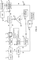
Figure 2 is a schematic of an EW RF receiver and optical linkage that utilises the distortion removal apparatus ofFig 1 . - There is shown a
laser 1, typically a distributed feedback laser, afirst splitter 2, apolarisation controller 3, a single sideband carrier suppressed (SSB(C))modulator 4, an optical medium 5 (typically a length of optical fibre -e.g. single mode fibre) in which a stimulated Brillion dynamic grating is produced; anoptical combiner 6, a high frequency photodiode 9, an analoguedigital converter 10 having an output for receipt by a digital EW system; adetuned modulator 12; aphotonic upconverter 13 tuned to upconvert an input by an anti-stokes frequency; an optical amplifier 14 (e.g. a EDFA); and asecond polarisation controller 15. - The apparatus further includes an
EW receiver 18 comprising a RF antenna and amplifier, and a wideband RF coupler 19. - An EW signal received by
receiver 18 is combined through the wideband RF coupler 19, (e.g. a Wilkinson coupler) with a local oscillator (lo) tuned to ensure the photodiode 9 beats at a frequency that theADC 10 can resolve. The output from thecoupler 19 is used to drivemodulators - The
laser 1 provides a coherent light beam, e.g. of a near-IR frequency, that is split byfirst splitter 2 into a first light beam L1 and a second light beam L2. - The first light beam L1 modulated by the SSB(C)
modulator 4 and the second light beam L2 is modulated by thedetuned modulator 12 such that both the first and third light beams L1 L2 carry EW signals fed fromreceiver 18. - Both the first and second modulators are optionally Mach Zehnder modulators. The first modulator is biased for high efficiency, e.g. to π/2.
- The detuned modulator L2 is biased at π such that L2 has a smaller ratio of the amplitude of the fundamental : amplitude of largest distortion products than L1.
- The amplitude of the distortion products in L2 may still be smaller than the amplitude of the fundamental (though an amplitude larger than the fundamental would be preferable).
- Modulated beam L2 is up converted by the antistokes frequency (typically ~11GHz depending on the material(s) used to construct the optical fibre) and then amplified by optical amplifier (e.g. of EDFA type or other) 14.
- The first beam L1 and second beam L2 are counter propagated through
optical fibre 5. The second beam L2 is of sufficient power to incite a Brillouin grating within theoptical fibre 5. -
Polarisation controllers fibre 5 at the correct orientation to provide the desired reflection of L1. This technique will be familiar to those skilled in the art. - Because the ratio of the amplitude of the fundamental : distortion products in the second beam L2 is lower than the ratio of the amplitude of the fundamental to distortion products in first beam L1, the grating preferentially reflects the distortion products within L1 over the fundamental, meaning that output beam L3, being that part of L1 transmitted through grating in
fibre 5, has a greater ratio of fundamental : distortion products than L1. L3 thus has a higher spectral free dynamic range than L1. - It will be appreciated that the amplitude of the distortions products in L2 need to be above a threshold level for the Brillouin grating to be effective at reflecting the distortion products carried by L1.
- The optical power of L2 can be adjusted through control of
amplifier 14. Favourably L2 is made to be sufficiently optically powerful to reduce all distortion products within L3 to below the noise floor. - By increasing the optical power of L2, the distortion products will be more strongly reflected which allows shortening of the
fibre 5 and thus reducing latency of the signal of L3 with respect to L1. Depending on the power of L2, and thus the efficiency of the grating, thefibre 5 may be between tens of metres to several kilometres in length. - Output beam L3 is received by photodiode 9 (optionally being amplified beforehand by a further amplifier such as a EDFA or equivalent) which outputs a corresponding electrical signal. The beat in the output of the photodiode 9 is detected by
ADC 10. In some embodiments an amplifier may be positioned to amplify the output from photodiode 9 inputted toADC 10. The output of the ADC may be fed to a digital EW system for analysis. - It will be appreciated that the
detuned modulator 12 may be biased other than at π, so long as the fundamental : distortion products ratio of the modulated second beam L2 is less than the modulated first beam L1. - Rather than using a
detuned modulator 12, a directly modulated laser may be used at low frequency (less than ~10GHz). This arrangement can naturally produce large distortion products. Where a directly modulated laser is used, it should of the same wavelength aslaser 1 and have a line width that is the same or greater thanlaser 1. - It may be possible to dispense with the
amplifier 14 if L2 is already sufficiently powerful. - The paths of the counter propagating beams should be arranged so that the counter propagating beams pass through the
fibre 5 at the same time in order to create the grating. This requires making the optical path lengths substantially the same taking into account delays caused by optical components and/or the laser's 1 pulse length. -
Figure 3 is a schematic of a variant EW RF receiver and optical linkage that utilises the distortion removal apparatus ofFig 1 and provides photonic mixing. Parts shared with the embodiment ofFig 2 are given like numbering. - There is shown a
laser 1, typically a distributed feedback laser, afirst splitter 2, apolarisation controller 3, a single sideband carrier suppressed (SSB(C))modulator 4, an optical medium 5(typically a length of optical fibre - e.g. single mode fibre) in which a stimulated Brillion dynamic grating is formed; anoptical combiner 6, a second polarisation control 7, a polarisation combiner 8, a high frequency photodiode 9, analoguedigital converter 10 having an output to a digital EW system; a secondoptical splitter 11, adetuned modulator 12; aphotonic upconverter 13 tuned to upconvert an input by an anti-stokes frequency; an optical amplifier (e.g. a EDFA); and athird polarisation controller 15. - The apparatus further comprises a tuned carrier suppressed
SSB converter 16 with appropriate local oscillator and a fourth polarisation controller 17. - The apparatus further includes an
EW receiver 18 comprising a RF antenna and amplifier that drives the SSB(C)modulator 4 anddetuned modulator 12. - The
laser 1 generates a coherent light beam, e.g. of a near-IR frequency, that is split byfirst splitter 2 into a first light beam B1 and a second light beam B2. The second light beams B2 is further split into a third light beam B3 and fourth light beam B4. - The first light beam B1 is modulated by the SSB(C)
modulator 4 and the third light beam B3 is modulated by thedetuned modulator 12 such that both the first and third light beams B1 B3 carry EW signals fed fromreceiver 18. - The
detuned modulator 12 could be a standard Mach Zehnder modulator (though other modulators could be used) biased at π such that the ratio of the amplitude of the fundamental : amplitude of largest distortion products in B3 is lower than the ratio of the amplitude of the fundamental : amplitude of largest distortion products in B1. The amplitude of the distortion products in B3 may still be smaller than the amplitude of the fundamental (though larger than the fundamental would be preferable). - Modulated third beam B3 is up converted by the antistokes frequency and amplified by
optical amplifier 14. - The first beam B1 and third beam B3 are transmitted through
optical fibre 5 in opposition to one another. The third beam B3 is of sufficient power as to form a Brillouin grating within theoptical fibre 5. -
Polarisation controllers fibre 5 at the correct orientation to provide the desired reflection of B1. - As before, because the ratio of the amplitude of the fundamental : distortion products in B3 is lower than the ratio of the amplitude of the fundamental :distortion products in B1, the grating preferentially reflects the distortion products over the fundamental meaning that output beam B5 that has transmitted through grating in
fibre 5 has a greater ratio of fundamental : distortion product than B1. - The optical power of B3 is preferably selected to ensure distortion products are suppressed down to below the noise floor.
- Fourth beam B4 is frequency converted by tuned carrier suppressed
SSB converter 16 by a frequency using a local oscillator tuned to be shifted from a frequency of interest; the size of the shift being within the resolution bandwidth of theADC 10. - Up converted fourth beam B4, and output beam B5 are combined in polarisation combiner 8 and the output (optionally amplified by a further amplifier) fed to photodiode 9. Combined beams B4 B5 generate a beat in the output of the photodiode 9 that is within the resolution bandwidth of
ADC 10. In some embodiments an amplifier may be positioned to amply the output from photodiode for input to ADC. The output of the ADC may be fed to a digital EW system for analysis. - Polarisation controllers 7 and 17 are used to control the polarisation of L5 and L4 into the polarisation combiner 8 to provide efficient combination. The arrangement of which will be familiar to those skilled in the art.
- It will be appreciated that the detuned modulator L2 may be biased elsewhere so long as the fundamental : distortion products ratio is less than in L1. Again, a directly modulated laser may be used instead of a
detuned modulator 12. - Rather than using
SSB converter 16 it may be possible instead to redirect Brillouin scattered light from the stimulated emission in the waveguide, e.g. by using a suitable optical fibre. -
Amplifier 14 may be dispensed with if B3 is sufficiently powerful. - The embodiments described above may optionally include a further optical amplifier (not shown) positioned in front of the photodiode to amplify the optical signal.
-
Figure 4 is a variant ofFigure 2 in which the output of the lo is fed into an I channel of themodulator 4 and the output of thereceiver 18 is fed into a Q channel of themodulator 4. This allows the RF coupler ofFigure 2 to be omitted. For further details of this implementation see Erwin H. W. Chan and Robert A. Minasian, "High conversion efficiency microwave photonic mixer based on stimulated Brillouin scattering carrier suppression technique," Opt. Lett. 38, 5292-5295 (2013). -
Figure 5 illustrates application of the invention used to reduce distortion of the output of an electronic mixer. - The optical link has the same configuration as that of
Figure 2 , with the difference that thefirst modulator 4 is arranged to modulate the first light beam to carry a signal using the output from a first electrical mixer 20A arranged to run at high power and low distortion. Thesecond modulator 12 is arranged to modulate the second light beam to carry the signal using the output of a second mixer 20B configured to run at high power and create high distortion. In this way the beam outputted frommodulator 12 will have a lower fundamental to distortion product ratio than the beam outputted frommodulator 4 such that the dynamic Brillouin grating formed infibre 5 will act to preferentially reflect (and thus suppress) distortion products from the output ofmodulator 4. - The optical link is conceived to have applications other than for connecting an RF receiver to processing system. For example, the optical link may be used to connect a RF transmitter to an antenna. In such an arrangement it may be favourable to upconvert the output from the grating before transmission to the antenna, e.g. using a electronic or photonic mixer. In such an arrangement the ADC could be dispensed with (as it could in any application were only an analogue output is required).
- The optical link may also have use in commercial telecommunication applications such as with a RF transmitter and/or RF receiver forming part of a broadband cellular network.
Claims (15)
- Apparatus for reducing distortion in an optical signal, the apparatus comprising:an optical waveguide (5);an input (18) for receiving a radio frequency (RF) signal;means (1, 4) for generating a first coherent light beam (L1) modulated to carry the RF signal received at the input (18),means (1, 2) for generating a second coherent light beam (L2);the optical frequency of the first light beam (L1) and second light beam (L2) differing to satisfy the Brillouin condition;the apparatus arranged to cause the first coherent light beam (L1) to propagate along the optical waveguide (5) in a first direction, and the second coherent light beam (L2) to propagate along the optical waveguide in an opposite direction to generate a dynamic Brillouin grating in the optical waveguide (5) through stimulated Brillouin scattering; andcharacterised in comprising means to modulate the second coherent light beam (L2) to carry the RF signal received at the input (18); and that the first and second light beams (L1) (L2) have different fundamental to distortion product ratios.
- Apparatus according to claim 1 wherein the second coherent light beam (L2) has a lower fundamental to distortion product ratio than the first coherent light beam (L1).
- Apparatus according to claim 2 wherein the means (1) for generating the first coherent light beam comprises a first optical modulator (4) tuned so as to be of relatively high efficiency & relatively highly linear compared with the means (12) for generating the modulated second coherent light beam, such that the first coherent light beam (L1) has a relatively high fundamental to distortion product ratio compared with the second coherent light beam (L2).
- Apparatus according to any claim 1-3 wherein the means (1,4) for generating the first coherent light beam (L1) comprises a single sideband, SSB, modulator (4).
- Apparatus according to any claim 1-4 wherein the means for generating a second coherent light beam (L2) comprises a detuned modulator (12) biased substantially at pi(π).
- Apparatus according to any previous claim wherein the means for generating the second coherent light beam (L2) comprises a single sideband, SSB, modulator (12).
- Apparatus according to any previous claim comprising means to shift the frequency (13) of the second optical beam (L2) relative to the first optical beam (L1) to meet the Brillouin condition.
- Apparatus according to any claim 2-7 comprising an optical receiver (9) arranged to receive a portion of the first light beam (L3) that has passed through the dynamic Brillouin grating.
- Apparatus according to claim 8 comprising an analogue-to-digital converter (10) arranged to receive an output from the optical receiver (9).
- Apparatus according to claim 8 or 9 comprising means (11, 16) for generating a third coherent light beam (B4) modulated with a frequency shifted from the radio frequency signal by a beat frequency, a polarisation combiner (8) arranged to combine an output optical signal (B5) that has passed through the Brillouin grating with the third beam (B4), and in which the optical receiver (9) is arranged to receive the output from the polarisation combiner (8) in order to output an electrical signal carrying the beat frequency.
- Apparatus according to any previous claim comprising an amplifier (14) arranged to amplify the modulated second coherent beam before it is propagated through the optical waveguide.
- Apparatus according to claim 11 wherein the amplifier (14) is arranged to amplify the second modulated light beam to a power to causes the grating to scatter optical distortion products of the first light beam to a sufficient extent that said distortion products in a portion of the light beam that has passed through the Brillouin grating are below the noise floor.
- A radio receiver system comprising a radio frequency receiver and an optical link, the optical link comprising the apparatus of claim 1.
- A method for reducing distortion in an optical signal, the method comprising:modulating a first coherent light beam to carry a radio frequency (RF) signal and propagating the modulated coherent light beam along an optical waveguide;generating a dynamic Brillouin grating in the optical waveguide using stimulated Brillouin scattering by propagating a second coherent light beam through the optical waveguide in an opposite direction to the first light beam, the optical frequency of the first coherent light beam and the second coherent light beam differing to satisfy the Brillouin condition; characterised in that the second coherent light beam is modulated to carry the RF signal received at the input and in which the first and second light beams are modulated so as to have different fundamental to distortion product ratios.
- A method according to claim 14 wherein the optical signal is carried by a photonic link connected to a RF receiver or RF transmitter, and in which the RF signal is received by the RF receiver or transmitted by the RF transmitter;
Applications Claiming Priority (2)
| Application Number | Priority Date | Filing Date | Title |
|---|---|---|---|
| GB1717084.6A GB2567646B8 (en) | 2017-10-18 | 2017-10-18 | Apparatus and method for reducing distortion of an optical signal |
| PCT/EP2018/078662 WO2019077090A1 (en) | 2017-10-18 | 2018-10-18 | Apparatus and method for reducing distortion of an optical signal |
Publications (2)
| Publication Number | Publication Date |
|---|---|
| EP3698490A1 EP3698490A1 (en) | 2020-08-26 |
| EP3698490B1 true EP3698490B1 (en) | 2021-09-22 |
Family
ID=60419132
Family Applications (1)
| Application Number | Title | Priority Date | Filing Date |
|---|---|---|---|
| EP18793197.7A Active EP3698490B1 (en) | 2017-10-18 | 2018-10-18 | Apparatus and method for reducing distortion of an optical signal |
Country Status (7)
| Country | Link |
|---|---|
| US (1) | US10897313B2 (en) |
| EP (1) | EP3698490B1 (en) |
| JP (1) | JP7102518B2 (en) |
| AU (1) | AU2018350865B2 (en) |
| ES (1) | ES2900382T3 (en) |
| GB (1) | GB2567646B8 (en) |
| WO (1) | WO2019077090A1 (en) |
Families Citing this family (2)
| Publication number | Priority date | Publication date | Assignee | Title |
|---|---|---|---|---|
| WO2020236260A1 (en) * | 2019-05-23 | 2020-11-26 | Massachusetts Institute Of Technology | Optical filtering to stabilize fiber amplifiers in the presence of stimulated brillouin scattering |
| CN111555813B (en) * | 2020-05-21 | 2022-03-08 | 西南石油大学 | Device and method for realizing transmitting frequency diversity array based on microwave photon frequency conversion |
Family Cites Families (9)
| Publication number | Priority date | Publication date | Assignee | Title |
|---|---|---|---|---|
| JP3425964B2 (en) * | 1992-03-19 | 2003-07-14 | 富士通株式会社 | Optical signal generator and optical transmission system using stimulated Brillouin scattering |
| DE10046941A1 (en) * | 2000-09-21 | 2002-04-25 | Siemens Ag | Method and arrangement for improving the signal quality of a modulated optical transmission signal |
| US7977454B2 (en) | 2005-07-08 | 2011-07-12 | Biocon Limited | Preparation of insulin conjugates |
| JP4100574B2 (en) * | 2005-12-01 | 2008-06-11 | 国立大学法人 東京大学 | Optical fiber characteristic measuring apparatus and optical fiber characteristic measuring method |
| US20080144897A1 (en) * | 2006-10-20 | 2008-06-19 | General Electric Company | Method for performing distributed analysis and interactive review of medical image data |
| JP2008139784A (en) * | 2006-12-05 | 2008-06-19 | Sumitomo Electric Ind Ltd | Optical signal noise suppression device and optical signal noise suppression method |
| KR20110075679A (en) * | 2009-12-28 | 2011-07-06 | 한국철도기술연구원 | Distributed Fiber Optic Sensor Device Using Brillouin Correlation Measurement and Its Sensing Method |
| EP3308217A4 (en) * | 2015-06-12 | 2018-10-31 | The University of Sydney | Microwave photonic notch filter |
| US10887015B2 (en) * | 2018-04-20 | 2021-01-05 | Eagle Technology, Llc | RF system with stimulated Brillouin scattering (SBS) photonic equalizer and related methods |
-
2017
- 2017-10-18 GB GB1717084.6A patent/GB2567646B8/en not_active Expired - Fee Related
-
2018
- 2018-10-18 WO PCT/EP2018/078662 patent/WO2019077090A1/en not_active Ceased
- 2018-10-18 US US16/757,092 patent/US10897313B2/en active Active
- 2018-10-18 ES ES18793197T patent/ES2900382T3/en active Active
- 2018-10-18 AU AU2018350865A patent/AU2018350865B2/en active Active
- 2018-10-18 EP EP18793197.7A patent/EP3698490B1/en active Active
- 2018-10-18 JP JP2020522067A patent/JP7102518B2/en active Active
Also Published As
| Publication number | Publication date |
|---|---|
| JP2021500613A (en) | 2021-01-07 |
| EP3698490A1 (en) | 2020-08-26 |
| GB201717084D0 (en) | 2017-11-29 |
| GB2567646B8 (en) | 2020-07-08 |
| ES2900382T3 (en) | 2022-03-16 |
| AU2018350865A1 (en) | 2020-04-23 |
| GB2567646A8 (en) | 2020-07-08 |
| AU2018350865B2 (en) | 2021-07-15 |
| US20200252134A1 (en) | 2020-08-06 |
| WO2019077090A1 (en) | 2019-04-25 |
| JP7102518B2 (en) | 2022-07-19 |
| US10897313B2 (en) | 2021-01-19 |
| GB2567646A (en) | 2019-04-24 |
| GB2567646B (en) | 2020-06-17 |
Similar Documents
| Publication | Publication Date | Title |
|---|---|---|
| US9698913B2 (en) | System and method for distortion correction in phase-encoded photonic links | |
| Williamson et al. | RF photonics | |
| US7146110B2 (en) | Optical transmitter with SBS suppression | |
| US5063559A (en) | Optimized wavelength-division-multiplexed lightwave communication system | |
| US9917651B2 (en) | Feed signal generation for a phased array antenna | |
| JP2018169487A (en) | Phase conjugate light generator, optical communication system, and phase conjugate light generation method | |
| US20110249932A1 (en) | Silicon integrated photonic optical parametric amplifier oscillator and wavelength converter | |
| Vidal et al. | Reconfigurable photonic microwave filter based on four-wave mixing | |
| AU2018350865B2 (en) | Apparatus and method for reducing distortion of an optical signal | |
| CN106559142A (en) | Light emitting devices, launching technique, optical pickup apparatus and method of reseptance | |
| Preussler et al. | Microwave-photonic filters | |
| Vidal et al. | Efficient architecture for WDM photonic microwave filters | |
| JP4494347B2 (en) | Light modulator | |
| Alic et al. | Two-pump parametric optical delays | |
| CN114389698B (en) | Microwave signal generating device and method | |
| US10749604B2 (en) | Optical phase distortion compensating device and method of compensating optical phase distortion | |
| Lin et al. | Tunable microwave photonics filter with dual pass-band based on PM-FBG and PS-FBG | |
| Udvary et al. | New microwave/millimeter wave true time delay device utilizing photonic approaches | |
| Bhatia et al. | Third-order distortion elimination in phase-encoded analog-photonic links using a four-wave mixing comb source | |
| Blatter et al. | Simple Single-Side Band Generation Scheme | |
| Udvary et al. | Variable microwave time delay by utilizing optical approaches | |
| JP2026504668A (en) | Generating multiple pulse trains from a micro-comb laser | |
| Yi et al. | Elimination of dispersion-induced RF distortion in spectrum sliced microwave photonic filters | |
| Almaiman et al. | Coarse and Fine Continuously Tunable Optical Delay Using the Time-of-flight in Fiber Bragg Gratings and Wavelength Conversion | |
| TW462151B (en) | Fiber optic transmitter for long distance broadband distribution system with the suppression of both stimulated Brillouin scattering and self/external phase modulation induced nonlinear distortion |
Legal Events
| Date | Code | Title | Description |
|---|---|---|---|
| STAA | Information on the status of an ep patent application or granted ep patent |
Free format text: STATUS: UNKNOWN |
|
| STAA | Information on the status of an ep patent application or granted ep patent |
Free format text: STATUS: THE INTERNATIONAL PUBLICATION HAS BEEN MADE |
|
| PUAI | Public reference made under article 153(3) epc to a published international application that has entered the european phase |
Free format text: ORIGINAL CODE: 0009012 |
|
| STAA | Information on the status of an ep patent application or granted ep patent |
Free format text: STATUS: REQUEST FOR EXAMINATION WAS MADE |
|
| 17P | Request for examination filed |
Effective date: 20200416 |
|
| AK | Designated contracting states |
Kind code of ref document: A1 Designated state(s): AL AT BE BG CH CY CZ DE DK EE ES FI FR GB GR HR HU IE IS IT LI LT LU LV MC MK MT NL NO PL PT RO RS SE SI SK SM TR |
|
| AX | Request for extension of the european patent |
Extension state: BA ME |
|
| DAV | Request for validation of the european patent (deleted) | ||
| DAX | Request for extension of the european patent (deleted) | ||
| GRAP | Despatch of communication of intention to grant a patent |
Free format text: ORIGINAL CODE: EPIDOSNIGR1 |
|
| STAA | Information on the status of an ep patent application or granted ep patent |
Free format text: STATUS: GRANT OF PATENT IS INTENDED |
|
| INTG | Intention to grant announced |
Effective date: 20210416 |
|
| RAP3 | Party data changed (applicant data changed or rights of an application transferred) |
Owner name: LEONARDO UK LTD |
|
| RIN1 | Information on inventor provided before grant (corrected) |
Inventor name: HAXHA, SHYQYRI Inventor name: ALOM, MOHAMMED Inventor name: FLINT, IAN |
|
| GRAS | Grant fee paid |
Free format text: ORIGINAL CODE: EPIDOSNIGR3 |
|
| GRAA | (expected) grant |
Free format text: ORIGINAL CODE: 0009210 |
|
| STAA | Information on the status of an ep patent application or granted ep patent |
Free format text: STATUS: THE PATENT HAS BEEN GRANTED |
|
| AK | Designated contracting states |
Kind code of ref document: B1 Designated state(s): AL AT BE BG CH CY CZ DE DK EE ES FI FR GB GR HR HU IE IS IT LI LT LU LV MC MK MT NL NO PL PT RO RS SE SI SK SM TR |
|
| REG | Reference to a national code |
Ref country code: GB Ref legal event code: FG4D |
|
| REG | Reference to a national code |
Ref country code: IE Ref legal event code: FG4D |
|
| REG | Reference to a national code |
Ref country code: DE Ref legal event code: R096 Ref document number: 602018024027 Country of ref document: DE |
|
| REG | Reference to a national code |
Ref country code: CH Ref legal event code: EP Ref country code: AT Ref legal event code: REF Ref document number: 1433133 Country of ref document: AT Kind code of ref document: T Effective date: 20211015 |
|
| REG | Reference to a national code |
Ref country code: SE Ref legal event code: TRGR |
|
| REG | Reference to a national code |
Ref country code: LT Ref legal event code: MG9D |
|
| REG | Reference to a national code |
Ref country code: NL Ref legal event code: FP |
|
| PG25 | Lapsed in a contracting state [announced via postgrant information from national office to epo] |
Ref country code: HR Free format text: LAPSE BECAUSE OF FAILURE TO SUBMIT A TRANSLATION OF THE DESCRIPTION OR TO PAY THE FEE WITHIN THE PRESCRIBED TIME-LIMIT Effective date: 20210922 Ref country code: FI Free format text: LAPSE BECAUSE OF FAILURE TO SUBMIT A TRANSLATION OF THE DESCRIPTION OR TO PAY THE FEE WITHIN THE PRESCRIBED TIME-LIMIT Effective date: 20210922 Ref country code: RS Free format text: LAPSE BECAUSE OF FAILURE TO SUBMIT A TRANSLATION OF THE DESCRIPTION OR TO PAY THE FEE WITHIN THE PRESCRIBED TIME-LIMIT Effective date: 20210922 Ref country code: BG Free format text: LAPSE BECAUSE OF FAILURE TO SUBMIT A TRANSLATION OF THE DESCRIPTION OR TO PAY THE FEE WITHIN THE PRESCRIBED TIME-LIMIT Effective date: 20211222 Ref country code: LT Free format text: LAPSE BECAUSE OF FAILURE TO SUBMIT A TRANSLATION OF THE DESCRIPTION OR TO PAY THE FEE WITHIN THE PRESCRIBED TIME-LIMIT Effective date: 20210922 Ref country code: NO Free format text: LAPSE BECAUSE OF FAILURE TO SUBMIT A TRANSLATION OF THE DESCRIPTION OR TO PAY THE FEE WITHIN THE PRESCRIBED TIME-LIMIT Effective date: 20211222 |
|
| REG | Reference to a national code |
Ref country code: AT Ref legal event code: MK05 Ref document number: 1433133 Country of ref document: AT Kind code of ref document: T Effective date: 20210922 |
|
| PG25 | Lapsed in a contracting state [announced via postgrant information from national office to epo] |
Ref country code: LV Free format text: LAPSE BECAUSE OF FAILURE TO SUBMIT A TRANSLATION OF THE DESCRIPTION OR TO PAY THE FEE WITHIN THE PRESCRIBED TIME-LIMIT Effective date: 20210922 Ref country code: GR Free format text: LAPSE BECAUSE OF FAILURE TO SUBMIT A TRANSLATION OF THE DESCRIPTION OR TO PAY THE FEE WITHIN THE PRESCRIBED TIME-LIMIT Effective date: 20211223 |
|
| REG | Reference to a national code |
Ref country code: ES Ref legal event code: FG2A Ref document number: 2900382 Country of ref document: ES Kind code of ref document: T3 Effective date: 20220316 |
|
| PG25 | Lapsed in a contracting state [announced via postgrant information from national office to epo] |
Ref country code: AT Free format text: LAPSE BECAUSE OF FAILURE TO SUBMIT A TRANSLATION OF THE DESCRIPTION OR TO PAY THE FEE WITHIN THE PRESCRIBED TIME-LIMIT Effective date: 20210922 |
|
| REG | Reference to a national code |
Ref country code: CH Ref legal event code: PL |
|
| PG25 | Lapsed in a contracting state [announced via postgrant information from national office to epo] |
Ref country code: IS Free format text: LAPSE BECAUSE OF FAILURE TO SUBMIT A TRANSLATION OF THE DESCRIPTION OR TO PAY THE FEE WITHIN THE PRESCRIBED TIME-LIMIT Effective date: 20220122 Ref country code: SK Free format text: LAPSE BECAUSE OF FAILURE TO SUBMIT A TRANSLATION OF THE DESCRIPTION OR TO PAY THE FEE WITHIN THE PRESCRIBED TIME-LIMIT Effective date: 20210922 Ref country code: RO Free format text: LAPSE BECAUSE OF FAILURE TO SUBMIT A TRANSLATION OF THE DESCRIPTION OR TO PAY THE FEE WITHIN THE PRESCRIBED TIME-LIMIT Effective date: 20210922 Ref country code: PT Free format text: LAPSE BECAUSE OF FAILURE TO SUBMIT A TRANSLATION OF THE DESCRIPTION OR TO PAY THE FEE WITHIN THE PRESCRIBED TIME-LIMIT Effective date: 20220124 Ref country code: PL Free format text: LAPSE BECAUSE OF FAILURE TO SUBMIT A TRANSLATION OF THE DESCRIPTION OR TO PAY THE FEE WITHIN THE PRESCRIBED TIME-LIMIT Effective date: 20210922 Ref country code: EE Free format text: LAPSE BECAUSE OF FAILURE TO SUBMIT A TRANSLATION OF THE DESCRIPTION OR TO PAY THE FEE WITHIN THE PRESCRIBED TIME-LIMIT Effective date: 20210922 Ref country code: CZ Free format text: LAPSE BECAUSE OF FAILURE TO SUBMIT A TRANSLATION OF THE DESCRIPTION OR TO PAY THE FEE WITHIN THE PRESCRIBED TIME-LIMIT Effective date: 20210922 Ref country code: AL Free format text: LAPSE BECAUSE OF FAILURE TO SUBMIT A TRANSLATION OF THE DESCRIPTION OR TO PAY THE FEE WITHIN THE PRESCRIBED TIME-LIMIT Effective date: 20210922 |
|
| REG | Reference to a national code |
Ref country code: DE Ref legal event code: R097 Ref document number: 602018024027 Country of ref document: DE Ref country code: BE Ref legal event code: MM Effective date: 20211031 |
|
| PG25 | Lapsed in a contracting state [announced via postgrant information from national office to epo] |
Ref country code: MC Free format text: LAPSE BECAUSE OF FAILURE TO SUBMIT A TRANSLATION OF THE DESCRIPTION OR TO PAY THE FEE WITHIN THE PRESCRIBED TIME-LIMIT Effective date: 20210922 |
|
| PG25 | Lapsed in a contracting state [announced via postgrant information from national office to epo] |
Ref country code: LU Free format text: LAPSE BECAUSE OF NON-PAYMENT OF DUE FEES Effective date: 20211018 Ref country code: DK Free format text: LAPSE BECAUSE OF FAILURE TO SUBMIT A TRANSLATION OF THE DESCRIPTION OR TO PAY THE FEE WITHIN THE PRESCRIBED TIME-LIMIT Effective date: 20210922 Ref country code: BE Free format text: LAPSE BECAUSE OF NON-PAYMENT OF DUE FEES Effective date: 20211031 |
|
| PLBE | No opposition filed within time limit |
Free format text: ORIGINAL CODE: 0009261 |
|
| STAA | Information on the status of an ep patent application or granted ep patent |
Free format text: STATUS: NO OPPOSITION FILED WITHIN TIME LIMIT |
|
| 26N | No opposition filed |
Effective date: 20220623 |
|
| PG25 | Lapsed in a contracting state [announced via postgrant information from national office to epo] |
Ref country code: LI Free format text: LAPSE BECAUSE OF NON-PAYMENT OF DUE FEES Effective date: 20211031 Ref country code: CH Free format text: LAPSE BECAUSE OF NON-PAYMENT OF DUE FEES Effective date: 20211031 |
|
| PG25 | Lapsed in a contracting state [announced via postgrant information from national office to epo] |
Ref country code: IE Free format text: LAPSE BECAUSE OF NON-PAYMENT OF DUE FEES Effective date: 20211018 |
|
| PG25 | Lapsed in a contracting state [announced via postgrant information from national office to epo] |
Ref country code: SI Free format text: LAPSE BECAUSE OF FAILURE TO SUBMIT A TRANSLATION OF THE DESCRIPTION OR TO PAY THE FEE WITHIN THE PRESCRIBED TIME-LIMIT Effective date: 20210922 |
|
| PG25 | Lapsed in a contracting state [announced via postgrant information from national office to epo] |
Ref country code: CY Free format text: LAPSE BECAUSE OF FAILURE TO SUBMIT A TRANSLATION OF THE DESCRIPTION OR TO PAY THE FEE WITHIN THE PRESCRIBED TIME-LIMIT Effective date: 20210922 |
|
| PG25 | Lapsed in a contracting state [announced via postgrant information from national office to epo] |
Ref country code: SM Free format text: LAPSE BECAUSE OF FAILURE TO SUBMIT A TRANSLATION OF THE DESCRIPTION OR TO PAY THE FEE WITHIN THE PRESCRIBED TIME-LIMIT Effective date: 20210922 Ref country code: HU Free format text: LAPSE BECAUSE OF FAILURE TO SUBMIT A TRANSLATION OF THE DESCRIPTION OR TO PAY THE FEE WITHIN THE PRESCRIBED TIME-LIMIT; INVALID AB INITIO Effective date: 20181018 |
|
| PG25 | Lapsed in a contracting state [announced via postgrant information from national office to epo] |
Ref country code: MK Free format text: LAPSE BECAUSE OF FAILURE TO SUBMIT A TRANSLATION OF THE DESCRIPTION OR TO PAY THE FEE WITHIN THE PRESCRIBED TIME-LIMIT Effective date: 20210922 |
|
| PG25 | Lapsed in a contracting state [announced via postgrant information from national office to epo] |
Ref country code: TR Free format text: LAPSE BECAUSE OF FAILURE TO SUBMIT A TRANSLATION OF THE DESCRIPTION OR TO PAY THE FEE WITHIN THE PRESCRIBED TIME-LIMIT Effective date: 20210922 |
|
| PG25 | Lapsed in a contracting state [announced via postgrant information from national office to epo] |
Ref country code: MT Free format text: LAPSE BECAUSE OF FAILURE TO SUBMIT A TRANSLATION OF THE DESCRIPTION OR TO PAY THE FEE WITHIN THE PRESCRIBED TIME-LIMIT Effective date: 20210922 |
|
| PGFP | Annual fee paid to national office [announced via postgrant information from national office to epo] |
Ref country code: NL Payment date: 20251021 Year of fee payment: 8 |
|
| PGFP | Annual fee paid to national office [announced via postgrant information from national office to epo] |
Ref country code: DE Payment date: 20251021 Year of fee payment: 8 |
|
| PGFP | Annual fee paid to national office [announced via postgrant information from national office to epo] |
Ref country code: GB Payment date: 20251022 Year of fee payment: 8 |
|
| PGFP | Annual fee paid to national office [announced via postgrant information from national office to epo] |
Ref country code: IT Payment date: 20251021 Year of fee payment: 8 |
|
| PGFP | Annual fee paid to national office [announced via postgrant information from national office to epo] |
Ref country code: FR Payment date: 20251030 Year of fee payment: 8 |
|
| PGFP | Annual fee paid to national office [announced via postgrant information from national office to epo] |
Ref country code: SE Payment date: 20251021 Year of fee payment: 8 |
|
| PGFP | Annual fee paid to national office [announced via postgrant information from national office to epo] |
Ref country code: ES Payment date: 20251216 Year of fee payment: 8 |