EP3698484B1 - Redundant wireless communication systems and methods to ensure radio service quality under abnormal conditions - Google Patents
Redundant wireless communication systems and methods to ensure radio service quality under abnormal conditions Download PDFInfo
- Publication number
- EP3698484B1 EP3698484B1 EP18789772.3A EP18789772A EP3698484B1 EP 3698484 B1 EP3698484 B1 EP 3698484B1 EP 18789772 A EP18789772 A EP 18789772A EP 3698484 B1 EP3698484 B1 EP 3698484B1
- Authority
- EP
- European Patent Office
- Prior art keywords
- repeater
- base station
- primary
- configuration
- communications
- Prior art date
- Legal status (The legal status is an assumption and is not a legal conclusion. Google has not performed a legal analysis and makes no representation as to the accuracy of the status listed.)
- Active
Links
Images



Classifications
-
- H—ELECTRICITY
- H04—ELECTRIC COMMUNICATION TECHNIQUE
- H04B—TRANSMISSION
- H04B7/00—Radio transmission systems, i.e. using radiation field
- H04B7/14—Relay systems
- H04B7/15—Active relay systems
-
- H—ELECTRICITY
- H04—ELECTRIC COMMUNICATION TECHNIQUE
- H04B—TRANSMISSION
- H04B7/00—Radio transmission systems, i.e. using radiation field
- H04B7/14—Relay systems
- H04B7/15—Active relay systems
- H04B7/155—Ground-based stations
- H04B7/15528—Control of operation parameters of a relay station to exploit the physical medium
-
- H—ELECTRICITY
- H04—ELECTRIC COMMUNICATION TECHNIQUE
- H04W—WIRELESS COMMUNICATION NETWORKS
- H04W24/00—Supervisory, monitoring or testing arrangements
- H04W24/04—Arrangements for maintaining operational condition
-
- H—ELECTRICITY
- H04—ELECTRIC COMMUNICATION TECHNIQUE
- H04W—WIRELESS COMMUNICATION NETWORKS
- H04W76/00—Connection management
- H04W76/10—Connection setup
- H04W76/15—Setup of multiple wireless link connections
-
- H—ELECTRICITY
- H04—ELECTRIC COMMUNICATION TECHNIQUE
- H04W—WIRELESS COMMUNICATION NETWORKS
- H04W88/00—Devices specially adapted for wireless communication networks, e.g. terminals, base stations or access point devices
- H04W88/08—Access point devices
Definitions
- a repeater system (such as a distributed antenna system (DAS), a single-node repeater, a radio frequency (RF) repeater, etc.) is typically used to improve the wireless radio frequency (RF) coverage provided by one or more base stations.
- a repeater typically picks up and sends radio signals to a base station via antenna with a directional radio pattern.
- a repeater system typically includes one or more master units that are communicatively coupled with a plurality of remote antenna units, where each remote antenna unit can be coupled directly to one or more of the master units or indirectly via one or more other remote antenna units and/or via one or more intermediary or expansion units.
- a repeater is typically used to improve the coverage provided by one or more base stations that are coupled to the master units. These base stations can be coupled to the master units via one or more cables or via a wireless connection, for example, using one or more donor antennas.
- the wireless service provided by the base stations can include commercial cellular service and/or private or public safety wireless communications.
- Safety-related RF systems are typically activated on demand or are operated continuously.
- the safety wireless capacity provided by a repeater and the associated base-station-related equipment during normal operations may not be sufficient in emergency situations (such as a fire or security event) due to the presence of many additional users of the safety wireless service.
- emergency situations such as a fire or security event
- a redundant configuration must be activated in a short amount of time otherwise dropped calls may occur.
- the signal distributing infrastructure of the system may be shared between private and public safety services, each operating on their own frequency bands.
- the assigned licensed bands for the German Public Safety Digital Radio (BDBOS) TETRA network in Germany are 380-385 MHz for uplink communications and 390-395 MHz in downlink communications.
- BDBOS German Public Safety Digital Radio
- different bands are used.
- 415-420 MHz may be used for uplink communications
- 425-430 MHz may be used for downlink communications for private safety services.
- Public safety signals are usually used by government agencies, such as police or fire, and public safety coverage is available from base stations provided across large geographic regions (for example, nationwide coverage).
- Private safety signal coverage in contrast, is usually found within specific facilities or other areas of private service responsibility, for example, for the use of facility operator.
- a repeater system may be implemented as an "active" system in the sense that the downlink and uplink RF signals are amplified before being repeated.
- Active repeater systems can be used, for example, in sport stadiums, buildings (hotels, malls, or trade centers), metro stations and airports, trains, and tunnels.
- Each base station can be coupled to the repeater system via one or more cables or via a wireless connection, for example, using one or more donor antennas. Repeater systems can be used in other applications.
- each base station coupled to a repeater system may be dedicated to the repeater system.
- the capacity of each base station coupled to a repeater system can also be shared among the repeater system and a base station antenna system that is co-located with the base station and/or shared among the repeater system and one or more other repeater systems.
- repeaters provide wireless communication coverage in buildings for commercial use and for public services, like rescue services.
- the repeater usually picks up the radio signal from a base station signal by an antenna with a directional radio pattern towards a specific base station.
- the coverage needs to be provided also in emergency situations or more generally under abnormal conditions, like fires or maintenance of the base station.
- a normal condition is defined for example, when the primary base station is on-duty and the primary signal line connecting the antenna with the repeater is undisturbed.
- An abnormal condition is defined for example, when the primary base station is off-duty due to maintenance, or the primary signal line is broken.
- Other abnormal condition examples may include a primary in-building signal path being broken, signal loss due to increase free space loss by obstacle and an antenna failure/damage/misalignment. Other abnormal conditions are possible.
- US 2008/232296 represents the closest prior art to the invention and discloses a relay broadband wireless communication system.
- the relay broadband wireless communication system includes a plurality of base stations, and one or more relay stations.
- the base stations perform communication with a relay station placed within a coverage area and generate state information to be provided to the relay station.
- the one or more relay stations are disposed at a location allowing communication with the plurality of base stations and select one or more serving base stations based on state information received from each of the base stations.
- Embodiments provide a wireless communication system that provides redundant communication between a repeater, primary base station and at least one secondary base station.
- a single repeater selectively implements stored configurations to establish alternative communications with a secondary base station or along secondary communication line to the primary base station when abnormal communications are detected between the repeater and the primary base station.
- the invention is described in the repeater according to independent claim 1; a method of communication according to the invention is given in independent claim 9.
- the dependent claims comprise preferred embodiments of the invention.
- Embodiments provide a wireless communication system with a redundant function for coverage in a building or similar coverage area.
- Embodiments employ a single repeater having at least one redundancy configuration that is designed to communicate with an auxiliary (secondary) base station (or along a secondary communication link that may or may not include a secondary base station) when a main (primary) base station (or primary communication line) is unavailable. Switching from one configuration to the other in embodiments happen within a very short time and thus provide uninterrupted wireless service within a building.
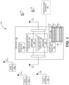
- a wireless communication system 90 having redundancy functions of an embodiment is illustrated.
- the communication system 90 in this example includes a single repeater 100, a primary base station 102, secondary base stations 110-1 through 110-n, antennas 130 and 116 and user equipment 114 and 115.
- the primary base station 102 includes a first base station antenna 104 that is in communication with the repeater100 via antenna 130.
- antenna 130 is used to communicate with the secondary base stations 110-1 through 110-n via respective secondary antennas 112-1 through 112-n.
- antenna 116 is used to communicate with user equipment 114 and 115 such as, but not limited to, mobile communication devices.
- the repeater 100 interfaces communications between the respective base stations 102, 110-1 through 110-n and the user equipment 114 and 115.
- the repeater 100 in this example is illustrated as including downlink repeater circuitry 119 and unlink repeater circuitry 120.
- the downlink repeater circuitry 119 is configured to receive one or more downlink signals from one or more base stations 102 and 110-1 through 110-n. These signals are also referred to here as "base station downlink signals.”
- Each base station downlink signal includes one or more radio frequency channels used for communicating in the downlink direction with the User Equipment (UE) 114 and 115 over the relevant wireless air interface.
- UE User Equipment
- each base station downlink signal is received as an analog radio frequency signal, though in some embodiments one or more of the base station signals are received in a digital form (for example, in some repeater systems implemented as a digital DAS, one or more of the base station downlink signals are received in a digital baseband form complying with, for example, the Common Public Radio Interface (“CPRI") protocol, Open Radio Equipment Interface (“ORI”) protocol, the Open Base Station Standard Initiative (“OBSAI”) protocol, or other protocol).
- CPRI Common Public Radio Interface
- ORI Open Radio Equipment Interface
- OBSAI Open Base Station Standard Initiative
- the downlink repeater circuitry 119 in the repeater system 100 is also configured to generate one or more downlink radio frequency signals that are radiated from one or more coverage antennas 116 associated with repeater system 100 for reception by LTE 114 and 115. These downlink radio frequency signals are analog radio frequency signals and are also referred to here as "repeated downlink radio frequency signals.” Each repeated downlink radio frequency signal includes one or more of the downlink radio frequency channels used for communicating with UE 114 and 115 over the wireless air interface.
- the repeater 100 is an active repeater system in which the downlink repeater circuitry 119 comprises one or more amplifiers (or other gain elements) 118 that are used to control and adjust the gain of the repeated downlink radio frequency signals radiated from the one or more coverage antennas 116.
- the downlink repeater circuitry 119 comprises one or more amplifiers (or other gain elements) 118 that are used to control and adjust the gain of the repeated downlink radio frequency signals radiated from the one or more coverage antennas 116.
- the repeater 100 comprises uplink repeater circuitry 120 that is configured to receive one or more uplink radio frequency signals transmitted from the UE 114 and 115. These signals are analog radio frequency signals and are also referred to here as "UE uplink radio frequency signals.” Each LTE uplink radio frequency signal includes one or more radio frequency channels used for communicating in the uplink direction with user equipment 114 and 115 over the relevant wireless air interface.
- the uplink repeater circuitry 120 in the repeater 100 is also configured to generate one or more uplink radio frequency signals that are provided to the one or more base stations 102 and 110-1 through 110-n. These signals are also referred to here as "repeated uplink signals.” Each repeated uplink signal includes one or more of the uplink radio frequency channels used for communicating with UE 114 and 115 over the wireless air interface.
- the repeater 100 is an active repeater system in which the uplink repeater circuitry 120 comprises one or more amplifiers (or other gain elements) 122 that are used to control and adjust the gain of the repeated uplink radio frequency signals provided to the one or more base stations 102 and 110-1 through 110-n.
- each repeated uplink signal is provided to the one or more base stations 102 and 110-1 through 110-n as an analog radio frequency signal, though in some embodiments one or more of the repeated uplink signals are provided to the one or more base stations 102 and 110-1 through 110-n in a digital form (for example, in some repeater systems implemented as a digital DAS, one or more of the repeated uplink signals are provided to one or more base stations 102, 110 in a digital baseband form complying with, for example, the CPRI protocol, ORI protocol, the OBSAI protocol, or other protocol).
- the downlink repeater circuitry 119 and uplink repeater circuitry 120 can comprise one or more appropriate connectors, attenuators, combiners, splitters, amplifiers, filters, duplexers, analog-to-digital converters, digital-to-analog converters, electrical-to-optical converters, optical-to-electrical converters, mixers, field-programmable gate arrays (FPGAs), microprocessors, transceivers, framers, etc., to implement the features described above. Also, the downlink repeater circuitry 119 and uplink repeater circuitry 120 may share common circuitry and/or components.
- the repeater 100 is configured to implement a detection function 124 that monitors communications between the repeater 100 and a base station.
- the detection function may quantify a power level of signals received at the repeater 100 in either or both of the uplink or downlink.
- the detection function 124 may be implemented to separately detect and quantify the received power for the relevant downlink and uplink frequency bands for each base station 102 and 110-1 through 110-n associated with the repeater 100.
- the detection function 124 can be implemented in other ways as further described below in detecting normal and abnormal communications.
- the repeater 100 of the example embodiment includes a controller 125 and memory 126.
- the memory 126 stores operating instructions implemented by the controller 125.
- the memory 126 further stores operating configurations that enables communications between the repeater 100 and base stations.
- the memory 126 includes a first (or primary) configuration 127 for communications the primary base station 102 and secondary configurations 128-1 through 128-n for communication with secondary base stations 110-1 through 1 10-n.
- at least one of the secondary configuration sets parameters for switching a communication link to at least one antenna as described in detail below.
- Information stored relating to the primary configuration 127 and the secondary configurations 128-1 through 128-n may include parameters such as a set of frequencies, gain values, conjugated parameters, relay status and descriptions used for respective configurations to enable communication between the repeater 100 and the respective base station 102 and 110-1 through 110-n.
- the detection function 124 is used to detect abnormal communications between the repeater 100 and the base stations 102, 110-1 through 110-n.
- the controller 125 of the repeater system 100 causes the repeater 100 to switch over to one of the secondary base stations 110-1 through 110-n upon the detection of abnormal communication with the primary base station 102 using a respective second configuration 128-1 through 128-n to set up communications with the respective secondary base station 110-1 through 110-n.
- the controller 125 of the repeater 100 may automatically switch back to communicating with the primary base station 102 implementing the primary configuration 127.
- the controller 125 may include any one or more of a processor, microprocessor, a digital signal processor (DSP), an application specific integrated circuit (ASIC), a field program gate array (FPGA), or equivalent discrete or integrated logic circuitry.
- controller 125 may include multiple components, such as any combination of one or more microprocessors, one or more controllers, one or more DSPs, one or more ASICs, one or more FPGAs, as well as other discrete or integrated logic circuitry.
- the functions attributed to the controller 125 herein may be embodied as software, firmware, hardware or any combination thereof.
- the controller may be part of a system controller or a component controller.
- the memory 126 may include computer-readable operating instructions as discussed above that, when executed by the controller 125 provides functions of the repeater system 100. Such functions may include the functions of switching communications between a primary base station and secondary base station as described above.
- the computer readable instructions may be encoded within the memory 126.
- Memory 126 may comprise computer readable storage media including any volatile, nonvolatile, magnetic, optical, or electrical media, such as, but not limited to, a random access memory (RAM), read-only memory (ROM), non-volatile RAM (NVRAM), electrically-erasable programmable ROM (EEPROM), flash memory, or any other storage medium.
- RAM random access memory
- ROM read-only memory
- NVRAM non-volatile RAM
- EEPROM electrically-erasable programmable ROM
- flash memory or any other storage medium.
- the communication system 90 may include a remote administration interface 140 that is in communication with the controller 125 of the repeater 100 as illustrated in Figure 1 .
- a current configuration of the repeater 100 is conveyed to the remote administrative interface 140.
- the remote administrative communication device 140 allows for the remote control the switching between the primary and secondary configurations 127 and 128-1 through 128-n.
- the remote administrative interface 140 is capable uploading new configurations on the repeater system in case frequency planning is changed by a network operator. This allows for a reduction in service costs since no local access is needed to load up new configurations.
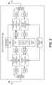
- a more detailed example of a single-node repeater 200 of another exemplary embodiment is illustrated in Figure 2 .
- the single-node repeater 200 is in communication with at least a primary base station (such as base station 102 of Figure 1 ) or secondary base station (such as one of the base stations 110-1 through 110-n of Figure 1 ) via first donor antenna 230.
- a second antenna 216 is used to receive and transmit signals to LTE (such LTE 114 and 115 of Figure 1 ).
- the single-node repeater 200 of this example embodiment comprises a first duplexer 202 having a common port that is coupled to the donor antenna 230 via cable.
- the single-node repeater 200 further comprises a low noise amplifier (LNA) 204 that is coupled to a downlink port of the first duplexer 202.
- the first duplexer 202 receives downlink signals from a base station (such as base station 102 and 110 of Figure 1 ) via the donor antenna 230 and outputs the received downlink signals to the LNA 204 via its downlink port.
- the LNA 204 amplifies the base station downlink signals.
- the single-node repeater 200 further comprises a downlink down-converter 206 that is coupled to the output of the LNA 204.
- the downlink down-converter 206 filters and down-converts the amplified downlink signals and outputs a down-converted downlink signal.
- the single-node repeater 200 further comprises a downlink analog-to-digital converter (ADC) 208 that is configured to digitize the down-converted downlink signal to produce real downlink digital samples indicative of the down-converted downlink signal (and the corresponding originally received downlink signal).
- ADC analog-to-digital converter
- the single-node repeater 200 further comprises a digital signal processor (DSP) unit or circuit 210.
- the DSP unit 210 is configured to digitally down-convert the real downlink digital samples to produce baseband digital in-phase and quadrature samples (IQ samples). These downlink digital IQ samples can also be filtered, amplified, attenuated, and/or re-sampled or decimated to a lower sample rate.
- the downlink down-converter 206 and downlink ADC 208 are configured to produce real digital samples for a relatively wide frequency band.
- the DSP unit 210 is configured to digitally filter the real digital samples to produce downlink digital IQ samples for a relatively narrow frequency band (also referred to here as a "downlink sub-band"), where the resulting downlink digital IQ samples for the downlink sub-band are then digitally amplified and/or otherwise digitally processed.
- the particular downlink sub-band that the single-node repeater 200 repeats, as well as the applied gain and/or other digital processing can be configured via software.
- the DSP unit 210 is configured to do this for multiple downlink sub-bands.
- the DSP unit 210 (more specifically, the software executing on the DSP unit 210) is configured to process multiple downlink sub-bands. An illustration of this is provided in Figure 3A .
- each sub-band has an associated downlink signal path 211-1 through 211-n.
- the signal path for each downlink sub-band comprises a digital down-converter (DDC) 213-1 through 213-n that digitally down-converts and filters the wideband real digital samples output by the ADC 208 in order to produce baseband downlink digital IQ samples for the associated downlink sub-band.
- the signal paths 211-1 through 211-n for each downlink sub-band also comprises one or more digital signal processing functions 215-1 through 215-n that adjust the gain (and/or otherwise digitally process) of the downlink sub-band signals.
- the signal paths 211-1 through 211-n for each downlink sub-band further include digital up-converters (DUCs) 217-1 through 217-n that digitally upconvert the processed baseband downlink digital IQ samples and produces upconverted wideband downlink digital IQ samples for all the downlink sub-bands.
- the upconverted wideband downlink digital IQ samples are then digitally summed using summer 219.
- the resulting summed wideband downlink digital IQ samples are output from the DSP unit 210.
- the settings used in each downlink signal path 211-1 through 211-n are software configurable. For example, the frequency range for each downlink sub-band and the gain adjustment or other signal processing can be changed via such settings. As discussed above, in embodiments, a controller changes the frequency range and gain adjustments in each sub-band when switching between a primary and secondary base station.
- the downlink DAC 212 produces analog in-phase and quadrature signals that are output to a downlink analog up-converter 214 that is included in the single-node repeater 200.
- the downlink analog up-converter 214 quadrature modulates the analog in-phase and quadrature signals to produce a real analog signal, which it up-converts to the desired RF frequency.
- the downlink analog up-converter 214 also filters the downlink analog radio frequency signal.
- the single-node repeater 200 further comprises a downlink power amplifier (PA) 216, which power amplifies the downlink analog radio frequency signal.
- PA downlink power amplifier
- the amplified downlink analog radio frequency signal is provided to a coverage antenna 216 associated with the single-node repeater 200 via a second duplexer 218, from which the amplified analog radio frequency signal is radiated to any user equipment (such as user equipment 114 and 115 of Figure 1 ) that is in the coverage area of the single-node repeater 200.
- the single-node repeater 200 further comprises a downlink frequency synthesizer 220 that is configured to generate a local oscillator signal used by the downlink down-converter 206 and the downlink up-converter 214.
- the single-node repeater 200 further comprises an uplink low noise amplifier (LNA) 222 that is coupled to an uplink port of the second duplexer 218.
- the second duplexer 218 receives any UE uplink radio frequency signals from any active user equipment 114, 115 via the associated coverage antenna 216 and outputs the received uplink signal to the LNA 222 via its uplink port.
- the LNA 222 amplifies the received uplink signals.
- the single-node repeater 200 further comprises an uplink analog down-converter 224 that is coupled to the output of the LNA 222.
- the uplink analog down-converter 224 filters and down-converts the amplified uplink signals and outputs a down-converted uplink signal.
- the single-node repeater 200 further comprises an uplink analog-to-digital converter (ADC) 226 that is configured to digitize the down-converted uplink signal to produce real downlink digital samples indicative of the down-converted uplink signal (and the corresponding originally received uplink signal).
- ADC uplink analog-to-digital converter
- the same DSP unit 210 is used for both downlink and uplink digital processing (though it is to be understood that separate DSP units could be used).
- the DSP unit 210 is configured to digitally down-convert the real uplink digital samples to produce baseband digital in-phase and quadrature samples. These uplink digital IQ samples can also be filtered, amplified, attenuated, and/or re-sampled or decimated to a lower sample rate.
- the uplink down-converter 224 and uplink ADC 226 are configured to produce real digital samples for a relatively wide frequency band.
- the DSP unit 210 is configured to digitally filter the real digital samples to produce uplink digital IQ samples for a relatively narrow frequency band (also referred to here as a "uplink sub-band"), where the resulting uplink digital IQ samples are then digitally amplified and/or otherwise digitally processed.
- uplink sub-band also referred to here as a "uplink sub-band”
- the particular uplink sub-band that the single-node repeater 200 repeats, as well as the applied gain and/or other digital processing can be configured via software.
- the DSP unit 210 is configured to do this for multiple uplink sub-bands.
- the DSP unit 210 of the example of Figure 2 (more specifically, the software executing on the DSP unit 210) is configured to process multiple uplink sub-bands as illustrated in Figure 3B .
- each sub-band has an associated uplink signal path 221-1 through 221-n.
- the signal path for each uplink sub-band comprises a digital down-converter (DDC) 223-1 through 221-n that digitally down-converts and filters the wideband real digital samples output by the ADC 226 to produce baseband uplink digital IQ samples for the associated uplink sub-band.
- the signal path 221-1 through 221-n for each uplink sub-band also comprises one or more digital signal processing functions 227-1 through 227-n that adjust the gain of (and/or otherwise digitally process) the uplink sub-band signals.
- the signal paths 221-1 through 221-n for each uplink sub-band also comprises a digital up-converter (DUC) 229-1 through 229-n that digitally upconverts the processed baseband uplink digital IQ samples and produces upconverted wideband uplink digital IQ samples for the samples for all the uplink sub-bands are then digitally summed using summer 231, and the resulting summed wideband uplink digital IQ samples are output from the DSP unit 210.
- the settings used in each uplink signal path 221-1 through 221-n are software configurable. For example, the frequency range for each uplink sub-band and the gain adjustment or other signal processing can be changed via such settings.
- the summed wideband uplink digital IQ samples output by the DSP unit 210 are provided to an uplink digital-to-analog (DAC) converter 228 that is included in the single-node repeater 200 as illustrated in Figure 2 .
- the uplink DAC 228 produces analog in-phase and quadrature signals that are output to an uplink analog up-converter 230 that is included in the single-node repeater 200.
- the uplink up-converter 230 quadrature modulates the analog in-phase and quadrature signals to produce a real analog signal, which it up-converts to the desired RF frequency.
- the uplink up-converter 230 also filters the uplink analog radio frequency signal.
- the single-node repeater 200 further comprises an uplink power amplifier (PA) 232, which power amplifies the uplink analog radio frequency signal.
- PA uplink power amplifier
- the amplified uplink analog radio frequency signal is provided to the donor antenna 230 via the second duplexer 202.
- the single-node repeater 200 further comprises an uplink frequency synthesizer 234 that is configured to generate a local oscillator signal that is used by the uplink down-converter 224 and the uplink up-converter 230.
- the single-node repeater 200 further comprises a controller 225.
- the controller 225 is implemented using one or more programmable processors that execute software that is configured to implement various features described here as being implemented by the controller 225 (or the single-node repeater 200 more generally).
- the controller 225 (more specifically, the various features described here as being implemented by the controller 225 or the single-node repeater 200) (or portions thereof) can be implemented in other ways (for example, in a field programmable gate array (FPGA), application specific integrated circuit (ASIC), etc.).
- FPGA field programmable gate array
- ASIC application specific integrated circuit
- the detection function 227 can be implemented in the DSP unit 210 to determine a received power level for the original uplink radio frequency signal received by the single-node repeater 200.
- the DSP unit 210 can determine the received power level based on the digital samples generated from the original uplink radio frequency signal received by the single-node repeater 200.
- the detection function is used to determine if a base station is offline. In further another embodiment, other methods of determining the presence and strength of a signal is used to determine if a base station is offline.
- the controller 225 implements first or second configuration instructions stored in memory when switching between a primary and secondary base station.
- the single-node repeater can be implemented in other ways (for example, where no digital signal processing is performed in the downlink and uplink repeater circuitry and instead only analog filtering and amplification is used).
- Flow diagram 400 is provided as a series of steps or blocks.
- the blocks in Figure 4 are provided in a sequential order. However, the sequential order is just an example. Other sequences are possible and anticipated. Hence embodiments are not limited to the sequence of blocks set out in Figure 4 .
- the status of a primary base station is monitored. If it is determined at block (404) that normal communications between the repeater and the primary base station is occurring or available, communications between the repeater and the primary base station is maintained at block (406).
- One method of determining if normal communication between the repeater and the primary base station is available is by monitoring signals from the primary base station. In one embodiment, this may be done with a detection function.
- a detection of an abnormal communication condition between the repeater and the primary base station at block (404) leads to a switching condition.
- a switching condition in the present invention being based on a Receive Signal Strength Indicator (RSSI) band measured by the detection function being less than a set RSSI threshold.
- the RSSI band is a RSSI measurement for the whole frequency band in the primary configuration.
- RSSI measurement is not limited to a specific measurement method, and a specific mobile communication standard.
- RSSI generally describes a measurement value which gives a clear indication if specific base station including the signal line on which the repeater is connected to the antenna, performs their intended tasks.
- the repeater selects a secondary base station to communicate with block (407).
- the secondary base stations are ranked. Higher ranked secondary base stations that are online and can provide normal communications are selected first.
- the secondary configuration associated with the selected secondary base station is activated at block (408).
- the implementation of the secondary configuration is achieved with a controller implementing secondary configuration instructions that are stored in a memory to allow communication between the repeater and the select secondary base station.
- the secondary configuration instructions may include information on frequencies, gains values, relay status, etc. that allow normal communications between the repeater the selected secondary base station.
- the repeater communicates with the secondary base station to provide interface functions between the LTE and the selected secondary base station.
- the communication status with the selected secondary base station is monitored at block (412). If it is determined that communication between the repeater and second base station is normal at block (414), it is then determined at block (416) whether the primary base station is once again able to provide normal communications. If it is determined at block (416) that the primary base station can provide normal communications, the primary configuration is activated at block (418) and the process continues at block (406) communicating with the primary base station using the first configuration.
- the communication with the secondary base station is maintained at block (410) and the process continues. If it determined at block (414) that the secondary base station is no longer able to provide normal communications, it is then determined at block (420) whether the primary base station is once again able to provide normal communications. If it is determined at block (420) that the primary base station can provide normal communications, the primary configuration is activated at block (418) and the process continues at block (406) communicating with the primary base using the first configuration. If, however, it is determined at block (420) that the primary base station still cannot provide normal communications, an alarm is activated or an alternative antenna is activated at block (422). The process then continues at block (402).
- the switching between the primary and secondary base stations is performed either automatically or manually.
- the switch over may be partially automatic and partially manual.
- the switching from the primary base station to the secondary base station upon detection of abnormal communications between the primary base station and the repeater may be automatic while the switching back to the primary base station may be manual.
- the manual switch may be done via remote administration interface.
- the repeater continues measuring the RSSI on both primary and secondary configurations regularly. This may occur within sub-second intervals.
- a controller of the repeater may continuously monitor just specific channels or different channels at different times in the background.
- the monitoring may not only determine indicators that a switching condition is present as explained above, but also may predetermine additional system parameters such as gain, to allow for an optimum radio service quality in the service area, in case an abnormal condition is present or the system resumes to a normal condition.
- embodiments are not limited to two configurations but may include different configurations which can be handled with different priorities.
- embodiments that employ a higher-ranking configuration system, when a higher-ranking base station comes back online or the disturbance of the higher-ranking signal line is resolved, embodiments automatically reactivate the higher-ranking configuration.
- Embodiments are not limited to only perform operations on the repeater configurations. Some embodiments allow for the transmitting of signal to external switching devices, such as RF relays, to perform additional tasks like transfer switching of communication lines as discussed further below. Additionally, embodiments of the repeater transmit the status, e.g. normal condition/abnormal condition via a separate communication channel to additional network elements, such as a remote administration interface. Moreover, some embodiments allow for the receiving of control signals from the remote administration interface to perform specific tasks about upcoming abnormal conditions, such as a scheduled maintenance of the primary base station. Another feature of an embodiment is to control the switching status of any connected switching device, such as a RF relay. If the switching status is not equivalent to the emitted switching command, an embodiment can use this information as another indication that an abnormal condition is present.
- Figure 5A illustrates a redundancy communication system 500 of a first exemplary embodiment.
- a repeater 510 is housed within a building 502.
- the repeater 510 includes a first (primary) configuration 512 used to communicate with a primary base station 530 and a secondary configuration 514 used to communicate via secondary communication link.
- the secondary communication link in this embodiment includes a secondary base station 540.
- one antenna 520 is used to communicate with both the primary base station 530 and the secondary base station 540.
- the antenna 520 in this example embodiment has preferably no directionality.
- the Example of Figure 5A illustrates normal conditions with the primary base station being online (or on duty) having normal communications with the repeater 510.
- the repeater 510 is in communication with the primary base station 530 using the primary configuration 512 as indicated by configuration indication 525.
- the primary and secondary configurations 512 and 514 use different frequencies and gain settings for the different base stations.
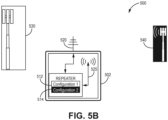
- Figure 5B illustrates redundancy communication system 500 where the primary base station 530 is offline (or off duty) and the secondary base station 540 is online via the repeater 510 activating the second configuration 514 as indicated by configuration indication 525.
- Figure 7D illustrates a redundancy communication system 770 of another exemplary embodiment.
- a repeater 710 is housed within a building 702.
- the repeater 710 includes a first configuration 712 used to communicate with a primary base station 730 and a secondary configuration 714 used to communicate with a secondary communication link that may or may not include the secondary base station 740.
- one antenna 720 is used to communicate with both the primary and secondary base stations 730 and 740.
- This embodiment further includes two RF relays.
- a first RF relay 724 is in communication with the repeater 710.
- the second RF relay 726 is in communication with the antenna 720.
- a signal line coupled between a first node of the first relay 724 and a first node of the second relay 726 form a primary communication line 731 and a signal line coupled between a second node of the first relay 724 and a second node of the second relay 726 form a secondary communication line 733.
- the primary and secondary communication lines 731 and 733 provide redundant communication links between the first and second RF relays 724 and 726.
- the first RF relay 724 is located within the building 702 and the second RF relay 726 is located outside the building 702. Both relays 724 and 726 is this embodiment provides relay feed back to the repeater 710.
- the RF relays 724 and 726 are activated with a TTL signal.
- the embodiment of Figure 7D also includes a remote administrative interface 734 that is in communication with the repeater 710. Hence, the relay position can be communicated to the remote administrative interface 734.
- the remote administrative interface 734 may control functions of the repeater 710 via implementing either the first configuration 712 or the secondary configuration 714 and the RF relay 724.
- a fire 737 causes an interruption in the primary communication line 731 from the RF relay 724 to the second RF relay 726.
- the first relay has been activated to the use the secondary communication line 733.
- the primary base station 730 is offline so the secondary configuration is used by the repeater 710 to communicate with the secondary base station 740.
- the second RF relay 726 may be used to provide a full backup of the primary communication signal line 731 via the secondary communication link.
- a relay test or a RSSI condition can be used to detect if an abnormal condition is present in the primary communication line 731. If it is detected that an abnormal condition is present in the primary communication line 731 but the primary base station 730 is still operational, the secondary communication line 733 (which is part of the secondary communication link) may be used to provide a communication link between the repeater 710 and the primary base station 730. This is accomplished by enacting a secondary configuration 714 that switches the relays to connect the secondary communication line 733.
- the secondary configuration 714 in this embodiment will include the same frequency group settings needed for communications with the primary base station 730 but may include different parameters, such as but not limited to, gains to accommodate the changed communication path.
- the activation can also be initiated manually by help of a remote administration interface 734.
- feedback from the relays is provided to the remote administrative interface 734 which conveys to the remote administrative interface 734 the then current base station configuration being used and the then current configuration of the relays 724 and 726. Further in an embodiment, the remote administrative interface 734 provides an user an option to cause the repeater 710 to automatically switch back to the use of the primary base station 730 and the primary communication line 731 once a normal condition is monitored or a manual switch back at an user's intervention.
- a cyclic cross check of the availability of the second base station is performed. This can be done in case one common antenna is used for both base stations. To do so, free filter resources of the DSP are used to check the RSSI of one (or several) carriers in the background. In the case where the carriers are available, switching is possible. This procedure can also be used to immediately set correct RF parameters (gain, output power, etc.) when activating an additional configuration.
Landscapes
- Engineering & Computer Science (AREA)
- Computer Networks & Wireless Communication (AREA)
- Signal Processing (AREA)
- Radio Relay Systems (AREA)
- Mobile Radio Communication Systems (AREA)
Description
- A repeater system (such as a distributed antenna system (DAS), a single-node repeater, a radio frequency (RF) repeater, etc.) is typically used to improve the wireless radio frequency (RF) coverage provided by one or more base stations. A repeater typically picks up and sends radio signals to a base station via antenna with a directional radio pattern. A repeater system typically includes one or more master units that are communicatively coupled with a plurality of remote antenna units, where each remote antenna unit can be coupled directly to one or more of the master units or indirectly via one or more other remote antenna units and/or via one or more intermediary or expansion units. A repeater is typically used to improve the coverage provided by one or more base stations that are coupled to the master units. These base stations can be coupled to the master units via one or more cables or via a wireless connection, for example, using one or more donor antennas. The wireless service provided by the base stations can include commercial cellular service and/or private or public safety wireless communications.
- The use of repeaters provides added capacity as well as additional coverage. Safety-related RF systems are typically activated on demand or are operated continuously. The safety wireless capacity provided by a repeater and the associated base-station-related equipment during normal operations may not be sufficient in emergency situations (such as a fire or security event) due to the presence of many additional users of the safety wireless service. As a result, it is common to provision systems used for such safety applications with additional base stations and repeaters. In safety-related systems a redundant configuration must be activated in a short amount of time otherwise dropped calls may occur.
- When planning for coverage within public safety relevant facilities by emergency services providers, the signal distributing infrastructure of the system may be shared between private and public safety services, each operating on their own frequency bands. For example, the assigned licensed bands for the German Public Safety Digital Radio (BDBOS) TETRA network in Germany are 380-385 MHz for uplink communications and 390-395 MHz in downlink communications. For private safety services, different bands are used. For example, 415-420 MHz may be used for uplink communications and 425-430 MHz may be used for downlink communications for private safety services. Public safety signals are usually used by government agencies, such as police or fire, and public safety coverage is available from base stations provided across large geographic regions (for example, nationwide coverage). Private safety signal coverage, in contrast, is usually found within specific facilities or other areas of private service responsibility, for example, for the use of facility operator.
- A repeater system may be implemented as an "active" system in the sense that the downlink and uplink RF signals are amplified before being repeated. Active repeater systems can be used, for example, in sport stadiums, buildings (hotels, malls, or trade centers), metro stations and airports, trains, and tunnels. Each base station can be coupled to the repeater system via one or more cables or via a wireless connection, for example, using one or more donor antennas. Repeater systems can be used in other applications.
- The capacity of each base station coupled to a repeater system may be dedicated to the repeater system. The capacity of each base station coupled to a repeater system can also be shared among the repeater system and a base station antenna system that is co-located with the base station and/or shared among the repeater system and one or more other repeater systems.
- As discussed above, repeaters provide wireless communication coverage in buildings for commercial use and for public services, like rescue services. The repeater usually picks up the radio signal from a base station signal by an antenna with a directional radio pattern towards a specific base station. For public services, the coverage needs to be provided also in emergency situations or more generally under abnormal conditions, like fires or maintenance of the base station. A normal condition is defined for example, when the primary base station is on-duty and the primary signal line connecting the antenna with the repeater is undisturbed. An abnormal condition is defined for example, when the primary base station is off-duty due to maintenance, or the primary signal line is broken. Other abnormal condition examples may include a primary in-building signal path being broken, signal loss due to increase free space loss by obstacle and an antenna failure/damage/misalignment. Other abnormal conditions are possible.
-
US 2008/232296 represents the closest prior art to the invention and discloses a relay broadband wireless communication system. The relay broadband wireless communication system includes a plurality of base stations, and one or more relay stations. The base stations perform communication with a relay station placed within a coverage area and generate state information to be provided to the relay station. The one or more relay stations are disposed at a location allowing communication with the plurality of base stations and select one or more serving base stations based on state information received from each of the base stations. - Embodiments provide a wireless communication system that provides redundant communication between a repeater, primary base station and at least one secondary base station. In embodiments, a single repeater selectively implements stored configurations to establish alternative communications with a secondary base station or along secondary communication line to the primary base station when abnormal communications are detected between the repeater and the primary base station. The invention is described in the repeater according to independent claim 1; a method of communication according to the invention is given in independent claim 9. The dependent claims comprise preferred embodiments of the invention.
-
-
Figure 1 is a block diagram of a wireless communication system having redundancy function according to one exemplary embodiment. -
Figure 2 is a block diagram of a repeater according to one exemplary embodiment; -
Figure 3A is a block diagram illustration the processing of multiple downlink sub-bands with a DSP unit according to one exemplary embodiment. -
Figure 3B is a block diagram illustration the processing of multiple uplink sub-bands with the DSP unit according to one exemplary embodiment. -
Figure 4 illustrates a redundancy flow diagram according to one exemplary embodiment. -
Figure 5A illustrates a redundant communication system implementing a normal primary configuration according to one exemplary embodiment. -
Figure 5B illustrates the redundant communication system ofFigure 5A implementing a secondary configuration according to one exemplary embodiment. -
Figure 7D illustrates another redundant communication system with a pair of relays implementing a secondary configuration according to one exemplary embodiment. - In accordance with common practice, the various described features are not drawn to scale but are drawn to emphasize specific features relevant to the subject matter described. Reference characters denote like elements throughout Figures and text.
- In the following detailed description, reference is made to the accompanying drawings, which form a part hereof, and in which is shown by way of illustration specific embodiments in which the inventions may be practiced. These embodiments are described in sufficient detail to enable those skilled in the art to practice the embodiments, and it is to be understood that other embodiments may be utilized and that changes may be made without departing from the spirit and scope of the present invention. The following detailed description is, therefore, not to be taken in a limiting sense, and the scope of the present invention is defined only by the claims and equivalents thereof.
- Embodiments provide a wireless communication system with a redundant function for coverage in a building or similar coverage area. Embodiments employ a single repeater having at least one redundancy configuration that is designed to communicate with an auxiliary (secondary) base station (or along a secondary communication link that may or may not include a secondary base station) when a main (primary) base station (or primary communication line) is unavailable. Switching from one configuration to the other in embodiments happen within a very short time and thus provide uninterrupted wireless service within a building. Referring to
Figure 1 , an example of awireless communication system 90 having redundancy functions of an embodiment is illustrated. Thecommunication system 90 in this example includes asingle repeater 100, aprimary base station 102, secondary base stations 110-1 through 110-n,antennas user equipment primary base station 102 includes a firstbase station antenna 104 that is in communication with the repeater100 viaantenna 130. In this example,antenna 130 is used to communicate with the secondary base stations 110-1 through 110-n via respective secondary antennas 112-1 through 112-n. Moreover,antenna 116 is used to communicate withuser equipment repeater 100 interfaces communications between therespective base stations 102, 110-1 through 110-n and theuser equipment - The
repeater 100 in this example is illustrated as includingdownlink repeater circuitry 119 andunlink repeater circuitry 120. In general, thedownlink repeater circuitry 119 is configured to receive one or more downlink signals from one ormore base stations 102 and 110-1 through 110-n. These signals are also referred to here as "base station downlink signals." Each base station downlink signal includes one or more radio frequency channels used for communicating in the downlink direction with the User Equipment (UE) 114 and 115 over the relevant wireless air interface. Typically, each base station downlink signal is received as an analog radio frequency signal, though in some embodiments one or more of the base station signals are received in a digital form (for example, in some repeater systems implemented as a digital DAS, one or more of the base station downlink signals are received in a digital baseband form complying with, for example, the Common Public Radio Interface ("CPRI") protocol, Open Radio Equipment Interface ("ORI") protocol, the Open Base Station Standard Initiative ("OBSAI") protocol, or other protocol). - The
downlink repeater circuitry 119 in therepeater system 100 is also configured to generate one or more downlink radio frequency signals that are radiated from one ormore coverage antennas 116 associated withrepeater system 100 for reception byLTE UE repeater 100 is an active repeater system in which thedownlink repeater circuitry 119 comprises one or more amplifiers (or other gain elements) 118 that are used to control and adjust the gain of the repeated downlink radio frequency signals radiated from the one ormore coverage antennas 116. - Also, the
repeater 100 comprisesuplink repeater circuitry 120 that is configured to receive one or more uplink radio frequency signals transmitted from theUE user equipment - The
uplink repeater circuitry 120 in therepeater 100 is also configured to generate one or more uplink radio frequency signals that are provided to the one ormore base stations 102 and 110-1 through 110-n. These signals are also referred to here as "repeated uplink signals." Each repeated uplink signal includes one or more of the uplink radio frequency channels used for communicating withUE repeater 100 is an active repeater system in which theuplink repeater circuitry 120 comprises one or more amplifiers (or other gain elements) 122 that are used to control and adjust the gain of the repeated uplink radio frequency signals provided to the one ormore base stations 102 and 110-1 through 110-n. - Typically, each repeated uplink signal is provided to the one or
more base stations 102 and 110-1 through 110-n as an analog radio frequency signal, though in some embodiments one or more of the repeated uplink signals are provided to the one ormore base stations 102 and 110-1 through 110-n in a digital form (for example, in some repeater systems implemented as a digital DAS, one or more of the repeated uplink signals are provided to one ormore base stations - The
downlink repeater circuitry 119 anduplink repeater circuitry 120 can comprise one or more appropriate connectors, attenuators, combiners, splitters, amplifiers, filters, duplexers, analog-to-digital converters, digital-to-analog converters, electrical-to-optical converters, optical-to-electrical converters, mixers, field-programmable gate arrays (FPGAs), microprocessors, transceivers, framers, etc., to implement the features described above. Also, thedownlink repeater circuitry 119 anduplink repeater circuitry 120 may share common circuitry and/or components. - The
repeater 100 is configured to implement adetection function 124 that monitors communications between therepeater 100 and a base station. In an embodiment, the detection function may quantify a power level of signals received at therepeater 100 in either or both of the uplink or downlink. In one embodiment, thedetection function 124 may be implemented to separately detect and quantify the received power for the relevant downlink and uplink frequency bands for eachbase station 102 and 110-1 through 110-n associated with therepeater 100. Thedetection function 124 can be implemented in other ways as further described below in detecting normal and abnormal communications. - The
repeater 100 of the example embodiment includes acontroller 125 andmemory 126. Thememory 126 stores operating instructions implemented by thecontroller 125. Thememory 126 further stores operating configurations that enables communications between therepeater 100 and base stations. In the example ofFigure 1 , thememory 126 includes a first (or primary)configuration 127 for communications theprimary base station 102 and secondary configurations 128-1 through 128-n for communication with secondary base stations 110-1 through 1 10-n. In some embodiments, at least one of the secondary configuration sets parameters for switching a communication link to at least one antenna as described in detail below. Information stored relating to theprimary configuration 127 and the secondary configurations 128-1 through 128-n may include parameters such as a set of frequencies, gain values, conjugated parameters, relay status and descriptions used for respective configurations to enable communication between therepeater 100 and therespective base station 102 and 110-1 through 110-n. - In the invention, as discussed in detail below, the
detection function 124 is used to detect abnormal communications between therepeater 100 and thebase stations 102, 110-1 through 110-n. Thecontroller 125 of therepeater system 100 causes therepeater 100 to switch over to one of the secondary base stations 110-1 through 110-n upon the detection of abnormal communication with theprimary base station 102 using a respective second configuration 128-1 through 128-n to set up communications with the respective secondary base station 110-1 through 110-n. In an embodiment, upon detection by thedetection function 124 that normal communications with theprimary base station 102 are restored (for example when the primary base station is brought back on line), thecontroller 125 of therepeater 100 may automatically switch back to communicating with theprimary base station 102 implementing theprimary configuration 127. - In general, the
controller 125 may include any one or more of a processor, microprocessor, a digital signal processor (DSP), an application specific integrated circuit (ASIC), a field program gate array (FPGA), or equivalent discrete or integrated logic circuitry. In some example embodiments,controller 125 may include multiple components, such as any combination of one or more microprocessors, one or more controllers, one or more DSPs, one or more ASICs, one or more FPGAs, as well as other discrete or integrated logic circuitry. The functions attributed to thecontroller 125 herein may be embodied as software, firmware, hardware or any combination thereof. The controller may be part of a system controller or a component controller. - The
memory 126 may include computer-readable operating instructions as discussed above that, when executed by thecontroller 125 provides functions of therepeater system 100. Such functions may include the functions of switching communications between a primary base station and secondary base station as described above. The computer readable instructions may be encoded within thememory 126.Memory 126 may comprise computer readable storage media including any volatile, nonvolatile, magnetic, optical, or electrical media, such as, but not limited to, a random access memory (RAM), read-only memory (ROM), non-volatile RAM (NVRAM), electrically-erasable programmable ROM (EEPROM), flash memory, or any other storage medium. - The
communication system 90 may include aremote administration interface 140 that is in communication with thecontroller 125 of therepeater 100 as illustrated inFigure 1 . In an embodiment, a current configuration of therepeater 100 is conveyed to the remoteadministrative interface 140. Further in an embodiment, the remoteadministrative communication device 140 allows for the remote control the switching between the primary andsecondary configurations 127 and 128-1 through 128-n. Further in an embodiment, the remoteadministrative interface 140 is capable uploading new configurations on the repeater system in case frequency planning is changed by a network operator. This allows for a reduction in service costs since no local access is needed to load up new configurations. - A more detailed example of a single-
node repeater 200 of another exemplary embodiment is illustrated inFigure 2 . The single-node repeater 200 is in communication with at least a primary base station (such asbase station 102 ofFigure 1 ) or secondary base station (such as one of the base stations 110-1 through 110-n ofFigure 1 ) viafirst donor antenna 230. Asecond antenna 216 is used to receive and transmit signals to LTE (such LTE Figure 1 ). The single-node repeater 200 of this example embodiment comprises afirst duplexer 202 having a common port that is coupled to thedonor antenna 230 via cable. - The single-
node repeater 200 further comprises a low noise amplifier (LNA) 204 that is coupled to a downlink port of thefirst duplexer 202. Thefirst duplexer 202 receives downlink signals from a base station (such asbase station Figure 1 ) via thedonor antenna 230 and outputs the received downlink signals to theLNA 204 via its downlink port. TheLNA 204 amplifies the base station downlink signals. - The single-
node repeater 200 further comprises a downlink down-converter 206 that is coupled to the output of theLNA 204. The downlink down-converter 206 filters and down-converts the amplified downlink signals and outputs a down-converted downlink signal. - The single-
node repeater 200 further comprises a downlink analog-to-digital converter (ADC) 208 that is configured to digitize the down-converted downlink signal to produce real downlink digital samples indicative of the down-converted downlink signal (and the corresponding originally received downlink signal). - The single-
node repeater 200 further comprises a digital signal processor (DSP) unit orcircuit 210. TheDSP unit 210 is configured to digitally down-convert the real downlink digital samples to produce baseband digital in-phase and quadrature samples (IQ samples). These downlink digital IQ samples can also be filtered, amplified, attenuated, and/or re-sampled or decimated to a lower sample rate. - In the exemplary embodiment shown in
FIG. 2 , the downlink down-converter 206 anddownlink ADC 208 are configured to produce real digital samples for a relatively wide frequency band. In this embodiment, theDSP unit 210 is configured to digitally filter the real digital samples to produce downlink digital IQ samples for a relatively narrow frequency band (also referred to here as a "downlink sub-band"), where the resulting downlink digital IQ samples for the downlink sub-band are then digitally amplified and/or otherwise digitally processed. In this way, the particular downlink sub-band that the single-node repeater 200 repeats, as well as the applied gain and/or other digital processing, can be configured via software. In this embodiment, theDSP unit 210 is configured to do this for multiple downlink sub-bands. - The DSP unit 210 (more specifically, the software executing on the DSP unit 210) is configured to process multiple downlink sub-bands. An illustration of this is provided in
Figure 3A . In this example, in each sub-band has an associated downlink signal path 211-1 through 211-n. The signal path for each downlink sub-band comprises a digital down-converter (DDC) 213-1 through 213-n that digitally down-converts and filters the wideband real digital samples output by theADC 208 in order to produce baseband downlink digital IQ samples for the associated downlink sub-band. The signal paths 211-1 through 211-n for each downlink sub-band also comprises one or more digital signal processing functions 215-1 through 215-n that adjust the gain (and/or otherwise digitally process) of the downlink sub-band signals. - The signal paths 211-1 through 211-n for each downlink sub-band further include digital up-converters (DUCs) 217-1 through 217-n that digitally upconvert the processed baseband downlink digital IQ samples and produces upconverted wideband downlink digital IQ samples for all the downlink sub-bands. The upconverted wideband downlink digital IQ samples are then digitally summed using
summer 219. The resulting summed wideband downlink digital IQ samples are output from theDSP unit 210. The settings used in each downlink signal path 211-1 through 211-n are software configurable. For example, the frequency range for each downlink sub-band and the gain adjustment or other signal processing can be changed via such settings. As discussed above, in embodiments, a controller changes the frequency range and gain adjustments in each sub-band when switching between a primary and secondary base station. - The summed wideband downlink digital IQ samples output by the
DSP unit 210 and provided to a downlink digital-to-analog converter (DAC) 212 that is included in the single-node repeater 200 as illustrated inFigure 2 . Thedownlink DAC 212 produces analog in-phase and quadrature signals that are output to a downlink analog up-converter 214 that is included in the single-node repeater 200. The downlink analog up-converter 214 quadrature modulates the analog in-phase and quadrature signals to produce a real analog signal, which it up-converts to the desired RF frequency. The downlink analog up-converter 214 also filters the downlink analog radio frequency signal. - The single-
node repeater 200 further comprises a downlink power amplifier (PA) 216, which power amplifies the downlink analog radio frequency signal. The amplified downlink analog radio frequency signal is provided to acoverage antenna 216 associated with the single-node repeater 200 via asecond duplexer 218, from which the amplified analog radio frequency signal is radiated to any user equipment (such asuser equipment Figure 1 ) that is in the coverage area of the single-node repeater 200. - The single-
node repeater 200 further comprises adownlink frequency synthesizer 220 that is configured to generate a local oscillator signal used by the downlink down-converter 206 and the downlink up-converter 214. - The single-
node repeater 200 further comprises an uplink low noise amplifier (LNA) 222 that is coupled to an uplink port of thesecond duplexer 218. Thesecond duplexer 218 receives any UE uplink radio frequency signals from anyactive user equipment coverage antenna 216 and outputs the received uplink signal to theLNA 222 via its uplink port. TheLNA 222 amplifies the received uplink signals. - The single-
node repeater 200 further comprises an uplink analog down-converter 224 that is coupled to the output of theLNA 222. The uplink analog down-converter 224 filters and down-converts the amplified uplink signals and outputs a down-converted uplink signal. - The single-
node repeater 200 further comprises an uplink analog-to-digital converter (ADC) 226 that is configured to digitize the down-converted uplink signal to produce real downlink digital samples indicative of the down-converted uplink signal (and the corresponding originally received uplink signal). - In the exemplary embodiment shown in
FIG. 2 , thesame DSP unit 210 is used for both downlink and uplink digital processing (though it is to be understood that separate DSP units could be used). TheDSP unit 210 is configured to digitally down-convert the real uplink digital samples to produce baseband digital in-phase and quadrature samples. These uplink digital IQ samples can also be filtered, amplified, attenuated, and/or re-sampled or decimated to a lower sample rate. - In the exemplary embodiment shown in
FIG. 2 , the uplink down-converter 224 and uplinkADC 226 are configured to produce real digital samples for a relatively wide frequency band. In this embodiment, theDSP unit 210 is configured to digitally filter the real digital samples to produce uplink digital IQ samples for a relatively narrow frequency band (also referred to here as a "uplink sub-band"), where the resulting uplink digital IQ samples are then digitally amplified and/or otherwise digitally processed. In this way, the particular uplink sub-band that the single-node repeater 200 repeats, as well as the applied gain and/or other digital processing, can be configured via software. In this embodiment, theDSP unit 210 is configured to do this for multiple uplink sub-bands. - In particular, the
DSP unit 210 of the example ofFigure 2 (more specifically, the software executing on the DSP unit 210) is configured to process multiple uplink sub-bands as illustrated inFigure 3B . In this example, in each sub-band has an associated uplink signal path 221-1 through 221-n. The signal path for each uplink sub-band comprises a digital down-converter (DDC) 223-1 through 221-n that digitally down-converts and filters the wideband real digital samples output by theADC 226 to produce baseband uplink digital IQ samples for the associated uplink sub-band. The signal path 221-1 through 221-n for each uplink sub-band also comprises one or more digital signal processing functions 227-1 through 227-n that adjust the gain of (and/or otherwise digitally process) the uplink sub-band signals. - The signal paths 221-1 through 221-n for each uplink sub-band also comprises a digital up-converter (DUC) 229-1 through 229-n that digitally upconverts the processed baseband uplink digital IQ samples and produces upconverted wideband uplink digital IQ samples for the samples for all the uplink sub-bands are then digitally summed using
summer 231, and the resulting summed wideband uplink digital IQ samples are output from theDSP unit 210. The settings used in each uplink signal path 221-1 through 221-n are software configurable. For example, the frequency range for each uplink sub-band and the gain adjustment or other signal processing can be changed via such settings. - The summed wideband uplink digital IQ samples output by the
DSP unit 210 are provided to an uplink digital-to-analog (DAC)converter 228 that is included in the single-node repeater 200 as illustrated inFigure 2 . Theuplink DAC 228 produces analog in-phase and quadrature signals that are output to an uplink analog up-converter 230 that is included in the single-node repeater 200. The uplink up-converter 230 quadrature modulates the analog in-phase and quadrature signals to produce a real analog signal, which it up-converts to the desired RF frequency. The uplink up-converter 230 also filters the uplink analog radio frequency signal. - The single-
node repeater 200 further comprises an uplink power amplifier (PA) 232, which power amplifies the uplink analog radio frequency signal. The amplified uplink analog radio frequency signal is provided to thedonor antenna 230 via thesecond duplexer 202. - The single-
node repeater 200 further comprises anuplink frequency synthesizer 234 that is configured to generate a local oscillator signal that is used by the uplink down-converter 224 and the uplink up-converter 230. - The single-
node repeater 200 further comprises acontroller 225. Thecontroller 225 is implemented using one or more programmable processors that execute software that is configured to implement various features described here as being implemented by the controller 225 (or the single-node repeater 200 more generally). The controller 225 (more specifically, the various features described here as being implemented by thecontroller 225 or the single-node repeater 200) (or portions thereof) can be implemented in other ways (for example, in a field programmable gate array (FPGA), application specific integrated circuit (ASIC), etc.). - In the exemplary shown in
FIG. 2 , thedetection function 227 can be implemented in theDSP unit 210 to determine a received power level for the original uplink radio frequency signal received by the single-node repeater 200. TheDSP unit 210 can determine the received power level based on the digital samples generated from the original uplink radio frequency signal received by the single-node repeater 200. In one embodiment, the detection function is used to determine if a base station is offline. In further another embodiment, other methods of determining the presence and strength of a signal is used to determine if a base station is offline. Thecontroller 225 implements first or second configuration instructions stored in memory when switching between a primary and secondary base station. - The single-node repeater can be implemented in other ways (for example, where no digital signal processing is performed in the downlink and uplink repeater circuitry and instead only analog filtering and amplification is used).
- Referring to
Figure 4 , a redundancy flow diagram 400 of an exemplary embodiment is illustrated. Flow diagram 400 is provided as a series of steps or blocks. The blocks inFigure 4 are provided in a sequential order. However, the sequential order is just an example. Other sequences are possible and anticipated. Hence embodiments are not limited to the sequence of blocks set out inFigure 4 . In the example ofFigure 4 , at block (402) the status of a primary base station is monitored. If it is determined at block (404) that normal communications between the repeater and the primary base station is occurring or available, communications between the repeater and the primary base station is maintained at block (406). One method of determining if normal communication between the repeater and the primary base station is available is by monitoring signals from the primary base station. In one embodiment, this may be done with a detection function. - A detection of an abnormal communication condition between the repeater and the primary base station at block (404) leads to a switching condition. A switching condition, in the present invention being based on a Receive Signal Strength Indicator (RSSI) band measured by the detection function being less than a set RSSI threshold. The RSSI band is a RSSI measurement for the whole frequency band in the primary configuration. There are other RSSI measurements possible. For example, the RSSI may be detected for a pilot channel, but different mobile communication standards could require different type of RSSI measurements. Therefore, the term "RSSI measurement" is not limited to a specific measurement method, and a specific mobile communication standard. RSSI generally describes a measurement value which gives a clear indication if specific base station including the signal line on which the repeater is connected to the antenna, performs their intended tasks.
- If it is determined that the communication between the repeater and primary base station is abnormal at block (404), the repeater selects a secondary base station to communicate with block (407). In one embodiment, the secondary base stations are ranked. Higher ranked secondary base stations that are online and can provide normal communications are selected first. The secondary configuration associated with the selected secondary base station is activated at block (408). As discussed above, in one embodiment the implementation of the secondary configuration is achieved with a controller implementing secondary configuration instructions that are stored in a memory to allow communication between the repeater and the select secondary base station. The secondary configuration instructions may include information on frequencies, gains values, relay status, etc. that allow normal communications between the repeater the selected secondary base station. At block (410) the repeater communicates with the secondary base station to provide interface functions between the LTE and the selected secondary base station.
- The communication status with the selected secondary base station is monitored at block (412). If it is determined that communication between the repeater and second base station is normal at block (414), it is then determined at block (416) whether the primary base station is once again able to provide normal communications. If it is determined at block (416) that the primary base station can provide normal communications, the primary configuration is activated at block (418) and the process continues at block (406) communicating with the primary base station using the first configuration.
- If it determined at block (416), that communications with the primary base station is still not available, the communication with the secondary base station is maintained at block (410) and the process continues. If it determined at block (414) that the secondary base station is no longer able to provide normal communications, it is then determined at block (420) whether the primary base station is once again able to provide normal communications. If it is determined at block (420) that the primary base station can provide normal communications, the primary configuration is activated at block (418) and the process continues at block (406) communicating with the primary base using the first configuration. If, however, it is determined at block (420) that the primary base station still cannot provide normal communications, an alarm is activated or an alternative antenna is activated at block (422). The process then continues at block (402).
- In the redundancy flow diagram 400 of an exemplary embodiment, the switching between the primary and secondary base stations is performed either automatically or manually. Moreover, in an embodiment, the switch over may be partially automatic and partially manual. For example, the switching from the primary base station to the secondary base station upon detection of abnormal communications between the primary base station and the repeater may be automatic while the switching back to the primary base station may be manual. In one embodiment, the manual switch may be done via remote administration interface.
- The repeater continues measuring the RSSI on both primary and secondary configurations regularly. This may occur within sub-second intervals. In addition, in an embodiment with a secondary configuration being active, a controller of the repeater may continuously monitor just specific channels or different channels at different times in the background. In addition, the monitoring may not only determine indicators that a switching condition is present as explained above, but also may predetermine additional system parameters such as gain, to allow for an optimum radio service quality in the service area, in case an abnormal condition is present or the system resumes to a normal condition.
- In addition, as discussed above, embodiments are not limited to two configurations but may include different configurations which can be handled with different priorities. In addition, some embodiments that employ a higher-ranking configuration system, when a higher-ranking base station comes back online or the disturbance of the higher-ranking signal line is resolved, embodiments automatically reactivate the higher-ranking configuration.
- Embodiments are not limited to only perform operations on the repeater configurations. Some embodiments allow for the transmitting of signal to external switching devices, such as RF relays, to perform additional tasks like transfer switching of communication lines as discussed further below. Additionally, embodiments of the repeater transmit the status, e.g. normal condition/abnormal condition via a separate communication channel to additional network elements, such as a remote administration interface. Moreover, some embodiments allow for the receiving of control signals from the remote administration interface to perform specific tasks about upcoming abnormal conditions, such as a scheduled maintenance of the primary base station. Another feature of an embodiment is to control the switching status of any connected switching device, such as a RF relay. If the switching status is not equivalent to the emitted switching command, an embodiment can use this information as another indication that an abnormal condition is present.
- Examples of different redundant wireless communication systems employing a repeater with first and second configurations to selectively communicate with a primary base station and a secondary base station are illustrated in
Figures 5A through 7D .Figure 5A illustrates aredundancy communication system 500 of a first exemplary embodiment. In theredundancy communication system 500, arepeater 510 is housed within abuilding 502. Therepeater 510 includes a first (primary)configuration 512 used to communicate with aprimary base station 530 and asecondary configuration 514 used to communicate via secondary communication link. The secondary communication link in this embodiment includes asecondary base station 540. In this example embodiment, oneantenna 520 is used to communicate with both theprimary base station 530 and thesecondary base station 540. Theantenna 520 in this example embodiment has preferably no directionality. - The Example of
Figure 5A illustrates normal conditions with the primary base station being online (or on duty) having normal communications with therepeater 510. InFigure 5A , therepeater 510 is in communication with theprimary base station 530 using theprimary configuration 512 as indicated byconfiguration indication 525. As discussed above, the primary andsecondary configurations antenna 520 to therepeater 510. If an abnormal condition is present with theprimary base station 530, therepeater 510 communicates with thesecondary base station 740. -
Figure 5B illustratesredundancy communication system 500 where theprimary base station 530 is offline (or off duty) and thesecondary base station 540 is online via therepeater 510 activating thesecond configuration 514 as indicated byconfiguration indication 525. -
Figure 7D illustrates aredundancy communication system 770 of another exemplary embodiment. Inredundancy communication system 770, arepeater 710 is housed within abuilding 702. Therepeater 710 includes afirst configuration 712 used to communicate with aprimary base station 730 and asecondary configuration 714 used to communicate with a secondary communication link that may or may not include thesecondary base station 740. In this example embodiment, oneantenna 720 is used to communicate with both the primary andsecondary base stations first RF relay 724 is in communication with therepeater 710. Thesecond RF relay 726 is in communication with theantenna 720. A signal line coupled between a first node of thefirst relay 724 and a first node of thesecond relay 726 form aprimary communication line 731 and a signal line coupled between a second node of thefirst relay 724 and a second node of thesecond relay 726 form asecondary communication line 733. The primary andsecondary communication lines first RF relay 724 is located within thebuilding 702 and thesecond RF relay 726 is located outside thebuilding 702. Bothrelays repeater 710. Moreover, in this example embodiment, the RF relays 724 and 726 are activated with a TTL signal. - The embodiment of
Figure 7D also includes a remoteadministrative interface 734 that is in communication with therepeater 710. Hence, the relay position can be communicated to the remoteadministrative interface 734. In an embodiment, the remoteadministrative interface 734 may control functions of therepeater 710 via implementing either thefirst configuration 712 or thesecondary configuration 714 and theRF relay 724. - In the example of
Figure 7D afire 737 causes an interruption in theprimary communication line 731 from theRF relay 724 to thesecond RF relay 726. In this example, the first relay has been activated to the use thesecondary communication line 733. Further in this example, theprimary base station 730 is offline so the secondary configuration is used by therepeater 710 to communicate with thesecondary base station 740. - In an embodiment, the
second RF relay 726 may be used to provide a full backup of the primarycommunication signal line 731 via the secondary communication link. In this embodiment, a relay test or a RSSI condition can be used to detect if an abnormal condition is present in theprimary communication line 731. If it is detected that an abnormal condition is present in theprimary communication line 731 but theprimary base station 730 is still operational, the secondary communication line 733 (which is part of the secondary communication link) may be used to provide a communication link between therepeater 710 and theprimary base station 730. This is accomplished by enacting asecondary configuration 714 that switches the relays to connect thesecondary communication line 733. Thesecondary configuration 714 in this embodiment will include the same frequency group settings needed for communications with theprimary base station 730 but may include different parameters, such as but not limited to, gains to accommodate the changed communication path. The activation can also be initiated manually by help of aremote administration interface 734. - In an embodiment, feedback from the relays is provided to the remote
administrative interface 734 which conveys to the remoteadministrative interface 734 the then current base station configuration being used and the then current configuration of therelays administrative interface 734 provides an user an option to cause therepeater 710 to automatically switch back to the use of theprimary base station 730 and theprimary communication line 731 once a normal condition is monitored or a manual switch back at an user's intervention. - In the present invention, while having the first configuration for the first base station active, a cyclic cross check of the availability of the second base station is performed. This can be done in case one common antenna is used for both base stations. To do so, free filter resources of the DSP are used to check the RSSI of one (or several) carriers in the background. In the case where the carriers are available, switching is possible. This procedure can also be used to immediately set correct RF parameters (gain, output power, etc.) when activating an additional configuration.
Claims (11)
- A repeater (100, 200, 510, 710) with redundancy functions for a distributed antenna system, the repeater (100, 200, 510, 710) comprising:downlink repeater circuitry (119) to interface communications from base stations (102, 110, 530, 540, 730, 740) to user equipment (114, 115);uplink repeater circuitry (120) to interface communications from the user equipment (114, 115) to the base stations (102, 110, 530, 540, 730, 740);at least one memory (126) to store a primary configuration (127, 512, 712) that sets out parameters for interfacing communications between the repeater (100, 200, 510, 710) and a primary base station (102, 530, 730) of the base stations (102, 110, 530, 540, 730, 740) along a primary communication link and at least one secondary configuration (128, 514, 714) that set out parameters for interfacing communications between the repeater (100, 200, 510, 710) and one of the primary base station (102, 530, 730) of the base stations (102, 110, 530, 540, 730, 740) and at least one secondary base station (110, 540, 740) of the base stations (102, 110, 530, 540, 730, 740) along a secondary communication link; anda controller (125) configured to implement the at least one secondary configuration (128, 514, 714) to communicate with the one of the primary base station (102, 530, 730) of the base stations (102, 110, 530, 540, 730, 740) and the at least one secondary base station (110, 540, 740) of the base stations (102, 110, 530, 540, 730, 740) along the secondary communication link upon the detection of a switching condition indicating abnormal communications on the primary communication link and carriers are available in the secondary communication link, wherein the at least one secondary configuration (128, 514, 714) includes at least a gain associated with the secondary communication link,characterized by further comprising:
a detection function configured, when using a common antenna for communications with each of the base stations (102, 110, 530, 540, 730, 740), to monitor communications in the primary communication link based on a measured receive signal strength indicator, RSSI, the detection function further configured to monitor in a background a RSSI in one or more carriers of the secondary communication link using a cyclic cross check using free filter resources of a digital signal processor, DSP, to check the RSSI of the one or more carriers in the background. - The repeater (100, 200, 510, 710) of claim 1, wherein the at least one secondary configuration (128, 514, 714) further includes include at least one of frequency, output power and relays status.
- A wireless communication system (90, 500, 770) having redundancy functions including the repeater (100, 200, 510, 710) of claim 1, the communication system comprising:a common antenna (130, 520, 720) to receive and transmit communications between the repeater (100, 200, 510, 710) and at least one of the primary base station (102, 530, 730) and the at least one secondary base station (110, 540, 740); andat least one of the primary communication link and the secondary communication link communicatively coupling the common antenna (130, 520, 720) to the repeater (100, 200, 510, 710).
- The communication system (90, 500, 770) of claim 3, further comprising:
a remote administrative interface (140) in communication with the controller (125) of the repeater (100, 200, 510, 710), the controller (125) further configured to share current configuration information of the repeater (100, 200, 510, 710) with the remote administrative interface (140), the controller (125) further configured to implement at least one of the primary configuration (127, 512, 712) and the at least one secondary configuration (128, 514, 714) based on an input from the remote administrative interface (140). - The communication system (770) of claim 3, further comprising:a first relay (724); anda second relay (726), the primary communication link coupled between a first node of the first relay (724) and a first node of the second relay (726) and the secondary communication link coupled between a second node of the first relay (724) and a second node of the second relay (726), the first relay (724) coupled to the repeater (100, 200, 710) and the second relay (726) coupled to the common antenna (720).
- The communication system (770) of claim 5, wherein the implementing the at least one secondary configuration switches the first and second relays (724, 726) to couple the repeater (100, 200, 510, 610, 710, 710) to the common antenna (720) via the secondary communication link.
- The communication system (90, 500, 770) of claim 3, wherein implementing the at least one secondary configuration (128, 514, 714) causes the repeater (100, 200, 510, 710) to communicate with the secondary base station (110, 540, 740).
- The communication system (90, 500, 770) of claim 3, wherein the controller (125) is further configured to automatically implement the primary configuration (127, 512, 712) upon the detection function detecting a normal communication condition between the repeater (100, 200, 710) and the primary base station (102, 530, 730).
- A method of operating a redundancy wireless communication system using a repeater (100, 200, 510, 710) that provides wireless communication coverage through a distributed antenna system, the method comprising:utilizing a common antenna to monitor communications between the repeater and a primary base station (102, 530, 730) through a primary communication line of the wireless communication system using a measured receive signal strength indicator, RSSI;utilizing the common antenna to monitor in a background RSSI in one or more carriers in a secondary communication line using a cyclic cross check using free filter resources of a digital signal processor, DSP, to check the RSSI of the one or more carriers in the background;implementing a secondary configuration (128, 514, 714) with the repeater upon detection of a switching condition indicating abnormal communications between the repeater (100, 200, 510, 710) and the primary base station (102, 530, 730) on the primary communication line; andestablishing communications between the repeater (100, 200, 510, 710) and one of the primary base station (102, 530, 730) and at least one secondary base station (110, 540, 740) pursuant to the implementation of the secondary configuration (128, 514, 714) by the repeater (100, 200, 510, 710) using the secondary communication line when carriers are available in the secondary communication link, wherein the secondary configuration (128, 514, 614, 714) includes a gain associated with the secondary communication link.
- The method of claim 9, wherein implementing the secondary configuration (714) with the repeater (710) further comprises:
switching a pair of relays (724, 726) to connect the secondary communication line between the repeater (710) and an antenna (720). - The method of claim 10, further comprising:activating the relays (724, 726) with a transistor-transistor logic signal; andproviding a relay feedback for each relay to the repeater (100, 200, 510, 710) to verify the status of the relays (724, 726).
Applications Claiming Priority (2)
| Application Number | Priority Date | Filing Date | Title |
|---|---|---|---|
| US201762573836P | 2017-10-18 | 2017-10-18 | |
| PCT/EP2018/078661 WO2019077089A1 (en) | 2017-10-18 | 2018-10-18 | Redundant wireless communication systems and methods to ensure radio service quality under abnormal conditions |
Publications (2)
| Publication Number | Publication Date |
|---|---|
| EP3698484A1 EP3698484A1 (en) | 2020-08-26 |
| EP3698484B1 true EP3698484B1 (en) | 2023-05-24 |
Family
ID=63921551
Family Applications (1)
| Application Number | Title | Priority Date | Filing Date |
|---|---|---|---|
| EP18789772.3A Active EP3698484B1 (en) | 2017-10-18 | 2018-10-18 | Redundant wireless communication systems and methods to ensure radio service quality under abnormal conditions |
Country Status (4)
| Country | Link |
|---|---|
| US (1) | US10735084B2 (en) |
| EP (1) | EP3698484B1 (en) |
| CN (1) | CN111213327A (en) |
| WO (1) | WO2019077089A1 (en) |
Families Citing this family (13)
| Publication number | Priority date | Publication date | Assignee | Title |
|---|---|---|---|---|
| US11838151B1 (en) | 2017-11-09 | 2023-12-05 | Verana Networks, Inc. | Wireless mesh network |
| US11375527B1 (en) * | 2017-11-09 | 2022-06-28 | Verana Networks, Inc. | Wireless mesh network |
| US11206549B1 (en) | 2017-11-09 | 2021-12-21 | Verana Networks, Inc. | Wireless mesh network |
| US11271699B1 (en) | 2017-11-09 | 2022-03-08 | Verana Networks, Inc. | Wireless mesh network |
| US11140695B1 (en) | 2017-11-09 | 2021-10-05 | Verana Networks, Inc. | Wireless mesh network |
| CN111903063B (en) | 2018-03-19 | 2022-08-12 | 皮沃塔尔卡姆瓦雷股份有限公司 | Transmit wireless signals through physical barriers |
| US11139929B2 (en) * | 2018-07-11 | 2021-10-05 | Qualcomm Incorporated | Enhanced reliability techniques for shared spectrum |
| US10468767B1 (en) | 2019-02-20 | 2019-11-05 | Pivotal Commware, Inc. | Switchable patch antenna |
| US11722207B2 (en) * | 2019-08-06 | 2023-08-08 | Commscope Technologies Llc | Repeater system using umbrella base station |
| KR102872581B1 (en) * | 2020-05-27 | 2025-10-17 | 피보탈 컴웨어 인코포레이티드 | RF signal repeater device management for 5G wireless networks |
| US20220045742A1 (en) * | 2020-08-04 | 2022-02-10 | Qualcomm Incorporated | Techniques for forwarding a wireless signal using a digital repeater |
| WO2023076405A1 (en) | 2021-10-26 | 2023-05-04 | Pivotal Commware, Inc. | Rf absorbing structures |
| JP2025512562A (en) | 2022-04-18 | 2025-04-17 | ピヴォタル コムウェア インコーポレイテッド | Time division duplex repeater timing recovery with global positioning satellite system |
Family Cites Families (12)
| Publication number | Priority date | Publication date | Assignee | Title |
|---|---|---|---|---|
| KR100973670B1 (en) * | 2007-03-21 | 2010-08-04 | 삼성전자주식회사 | Relay link operation apparatus and method in a relay wideband wireless communication system |
| KR100893010B1 (en) * | 2007-05-21 | 2009-04-10 | 주식회사 케이티프리텔 | Variable Attenuation Method of Repeater with Attenuation Device and Remote Management System |
| CN102083126A (en) * | 2009-11-27 | 2011-06-01 | 诺基亚西门子通信公司 | Relay node switching for different transceivers used for different repeated links |
| CN101719783B (en) * | 2009-12-18 | 2013-12-18 | 中兴通讯股份有限公司 | Control method and device of frequency selection repeater and frequency selection repeater |
| CN101917361B (en) * | 2010-06-12 | 2016-09-07 | 深圳国人通信有限公司 | Method, system and the repeater of a kind of carrier frequency that repeater is set |
| KR101753201B1 (en) * | 2011-03-01 | 2017-07-04 | 아주대학교산학협력단 | Apparatus and method for controlling relay in a communication system |
| US9198205B2 (en) * | 2011-04-06 | 2015-11-24 | Nokia Solutions And Networks Oy | Apparatus and method for communication |
| US8447307B2 (en) * | 2011-10-21 | 2013-05-21 | Telefonaktiebolaget L M Ericsson (Publ) | Handover for an intermediate node in a wireless communication network |
| US10419100B2 (en) * | 2012-05-07 | 2019-09-17 | Andrew Wireless Systems Gmbh | Doppler shift correction sub-system for communication device |
| US9112549B2 (en) * | 2012-10-05 | 2015-08-18 | Dali Systems Co. Ltd. | DAS integrated digital off-air repeater |
| US20150011157A1 (en) * | 2013-07-03 | 2015-01-08 | Wireless Extenders, Inc. | Multi-amplifier booster for a wireless communication system |
| US10171159B1 (en) * | 2017-03-07 | 2019-01-01 | Sprint Spectrum L.P. | Donor selection for relay access nodes using reference signal boosting |
-
2018
- 2018-10-18 EP EP18789772.3A patent/EP3698484B1/en active Active
- 2018-10-18 WO PCT/EP2018/078661 patent/WO2019077089A1/en not_active Ceased
- 2018-10-18 CN CN201880067359.7A patent/CN111213327A/en active Pending
- 2018-10-18 US US16/164,189 patent/US10735084B2/en active Active
Also Published As
| Publication number | Publication date |
|---|---|
| US10735084B2 (en) | 2020-08-04 |
| US20190115972A1 (en) | 2019-04-18 |
| WO2019077089A1 (en) | 2019-04-25 |
| CN111213327A (en) | 2020-05-29 |
| EP3698484A1 (en) | 2020-08-26 |
Similar Documents
| Publication | Publication Date | Title |
|---|---|---|
| US10735084B2 (en) | Redundant wireless communication systems and methods to ensure radio service quality under abnormal conditions | |
| EP3631400B1 (en) | Systems and methods for communication link redundancy for distributed antenna systems | |
| US9306682B2 (en) | Systems and methods for a self-optimizing distributed antenna system | |
| US8106826B2 (en) | Antenna arrangement | |
| US11563549B2 (en) | Selectable band suppression for a distributed antenna system | |
| EP3718225B1 (en) | Systems and methods for emergency operation of a wireless communication system | |
| US11166146B2 (en) | Combined riser in building emergency repeater system | |
| US20160205643A1 (en) | Wireless communication network repeater | |
| US20080214221A1 (en) | Radio Base Station System | |
| US12520244B2 (en) | Gain autotune | |
| EP3494758B1 (en) | Automatic configuration of a digital das for signal dominance | |
| US11838045B2 (en) | System and method for controlling an antenna system | |
| KR101675231B1 (en) | Relay apparatus | |
| WO2023002602A1 (en) | Communication system, communication method, and communication device |
Legal Events
| Date | Code | Title | Description |
|---|---|---|---|
| STAA | Information on the status of an ep patent application or granted ep patent |
Free format text: STATUS: UNKNOWN |
|
| STAA | Information on the status of an ep patent application or granted ep patent |
Free format text: STATUS: THE INTERNATIONAL PUBLICATION HAS BEEN MADE |
|
| PUAI | Public reference made under article 153(3) epc to a published international application that has entered the european phase |
Free format text: ORIGINAL CODE: 0009012 |
|
| STAA | Information on the status of an ep patent application or granted ep patent |
Free format text: STATUS: REQUEST FOR EXAMINATION WAS MADE |
|
| 17P | Request for examination filed |
Effective date: 20200506 |
|
| AK | Designated contracting states |
Kind code of ref document: A1 Designated state(s): AL AT BE BG CH CY CZ DE DK EE ES FI FR GB GR HR HU IE IS IT LI LT LU LV MC MK MT NL NO PL PT RO RS SE SI SK SM TR |
|
| AX | Request for extension of the european patent |
Extension state: BA ME |
|
| DAV | Request for validation of the european patent (deleted) | ||
| DAX | Request for extension of the european patent (deleted) | ||
| STAA | Information on the status of an ep patent application or granted ep patent |
Free format text: STATUS: EXAMINATION IS IN PROGRESS |
|
| 17Q | First examination report despatched |
Effective date: 20210506 |
|
| GRAP | Despatch of communication of intention to grant a patent |
Free format text: ORIGINAL CODE: EPIDOSNIGR1 |
|
| STAA | Information on the status of an ep patent application or granted ep patent |
Free format text: STATUS: GRANT OF PATENT IS INTENDED |
|
| INTG | Intention to grant announced |
Effective date: 20221213 |
|
| GRAS | Grant fee paid |
Free format text: ORIGINAL CODE: EPIDOSNIGR3 |
|
| GRAA | (expected) grant |
Free format text: ORIGINAL CODE: 0009210 |
|
| STAA | Information on the status of an ep patent application or granted ep patent |
Free format text: STATUS: THE PATENT HAS BEEN GRANTED |
|
| AK | Designated contracting states |
Kind code of ref document: B1 Designated state(s): AL AT BE BG CH CY CZ DE DK EE ES FI FR GB GR HR HU IE IS IT LI LT LU LV MC MK MT NL NO PL PT RO RS SE SI SK SM TR |
|
| REG | Reference to a national code |
Ref country code: GB Ref legal event code: FG4D |
|
| REG | Reference to a national code |
Ref country code: CH Ref legal event code: EP |
|
| REG | Reference to a national code |
Ref country code: DE Ref legal event code: R096 Ref document number: 602018050226 Country of ref document: DE |
|
| REG | Reference to a national code |
Ref country code: AT Ref legal event code: REF Ref document number: 1570200 Country of ref document: AT Kind code of ref document: T Effective date: 20230615 |
|
| REG | Reference to a national code |
Ref country code: IE Ref legal event code: FG4D |
|
| REG | Reference to a national code |
Ref country code: LT Ref legal event code: MG9D |
|
| REG | Reference to a national code |
Ref country code: NL Ref legal event code: MP Effective date: 20230524 |
|
| PG25 | Lapsed in a contracting state [announced via postgrant information from national office to epo] |
Ref country code: SE Free format text: LAPSE BECAUSE OF FAILURE TO SUBMIT A TRANSLATION OF THE DESCRIPTION OR TO PAY THE FEE WITHIN THE PRESCRIBED TIME-LIMIT Effective date: 20230524 Ref country code: PT Free format text: LAPSE BECAUSE OF FAILURE TO SUBMIT A TRANSLATION OF THE DESCRIPTION OR TO PAY THE FEE WITHIN THE PRESCRIBED TIME-LIMIT Effective date: 20230925 Ref country code: NO Free format text: LAPSE BECAUSE OF FAILURE TO SUBMIT A TRANSLATION OF THE DESCRIPTION OR TO PAY THE FEE WITHIN THE PRESCRIBED TIME-LIMIT Effective date: 20230824 Ref country code: NL Free format text: LAPSE BECAUSE OF FAILURE TO SUBMIT A TRANSLATION OF THE DESCRIPTION OR TO PAY THE FEE WITHIN THE PRESCRIBED TIME-LIMIT Effective date: 20230524 Ref country code: ES Free format text: LAPSE BECAUSE OF FAILURE TO SUBMIT A TRANSLATION OF THE DESCRIPTION OR TO PAY THE FEE WITHIN THE PRESCRIBED TIME-LIMIT Effective date: 20230524 |
|
| PG25 | Lapsed in a contracting state [announced via postgrant information from national office to epo] |
Ref country code: RS Free format text: LAPSE BECAUSE OF FAILURE TO SUBMIT A TRANSLATION OF THE DESCRIPTION OR TO PAY THE FEE WITHIN THE PRESCRIBED TIME-LIMIT Effective date: 20230524 Ref country code: PL Free format text: LAPSE BECAUSE OF FAILURE TO SUBMIT A TRANSLATION OF THE DESCRIPTION OR TO PAY THE FEE WITHIN THE PRESCRIBED TIME-LIMIT Effective date: 20230524 Ref country code: LV Free format text: LAPSE BECAUSE OF FAILURE TO SUBMIT A TRANSLATION OF THE DESCRIPTION OR TO PAY THE FEE WITHIN THE PRESCRIBED TIME-LIMIT Effective date: 20230524 Ref country code: LT Free format text: LAPSE BECAUSE OF FAILURE TO SUBMIT A TRANSLATION OF THE DESCRIPTION OR TO PAY THE FEE WITHIN THE PRESCRIBED TIME-LIMIT Effective date: 20230524 Ref country code: IS Free format text: LAPSE BECAUSE OF FAILURE TO SUBMIT A TRANSLATION OF THE DESCRIPTION OR TO PAY THE FEE WITHIN THE PRESCRIBED TIME-LIMIT Effective date: 20230924 Ref country code: HR Free format text: LAPSE BECAUSE OF FAILURE TO SUBMIT A TRANSLATION OF THE DESCRIPTION OR TO PAY THE FEE WITHIN THE PRESCRIBED TIME-LIMIT Effective date: 20230524 Ref country code: GR Free format text: LAPSE BECAUSE OF FAILURE TO SUBMIT A TRANSLATION OF THE DESCRIPTION OR TO PAY THE FEE WITHIN THE PRESCRIBED TIME-LIMIT Effective date: 20230825 |
|
| PG25 | Lapsed in a contracting state [announced via postgrant information from national office to epo] |
Ref country code: FI Free format text: LAPSE BECAUSE OF FAILURE TO SUBMIT A TRANSLATION OF THE DESCRIPTION OR TO PAY THE FEE WITHIN THE PRESCRIBED TIME-LIMIT Effective date: 20230524 |
|
| PG25 | Lapsed in a contracting state [announced via postgrant information from national office to epo] |
Ref country code: SK Free format text: LAPSE BECAUSE OF FAILURE TO SUBMIT A TRANSLATION OF THE DESCRIPTION OR TO PAY THE FEE WITHIN THE PRESCRIBED TIME-LIMIT Effective date: 20230524 |
|
| PG25 | Lapsed in a contracting state [announced via postgrant information from national office to epo] |
Ref country code: SM Free format text: LAPSE BECAUSE OF FAILURE TO SUBMIT A TRANSLATION OF THE DESCRIPTION OR TO PAY THE FEE WITHIN THE PRESCRIBED TIME-LIMIT Effective date: 20230524 Ref country code: SK Free format text: LAPSE BECAUSE OF FAILURE TO SUBMIT A TRANSLATION OF THE DESCRIPTION OR TO PAY THE FEE WITHIN THE PRESCRIBED TIME-LIMIT Effective date: 20230524 Ref country code: RO Free format text: LAPSE BECAUSE OF FAILURE TO SUBMIT A TRANSLATION OF THE DESCRIPTION OR TO PAY THE FEE WITHIN THE PRESCRIBED TIME-LIMIT Effective date: 20230524 Ref country code: EE Free format text: LAPSE BECAUSE OF FAILURE TO SUBMIT A TRANSLATION OF THE DESCRIPTION OR TO PAY THE FEE WITHIN THE PRESCRIBED TIME-LIMIT Effective date: 20230524 Ref country code: DK Free format text: LAPSE BECAUSE OF FAILURE TO SUBMIT A TRANSLATION OF THE DESCRIPTION OR TO PAY THE FEE WITHIN THE PRESCRIBED TIME-LIMIT Effective date: 20230524 Ref country code: CZ Free format text: LAPSE BECAUSE OF FAILURE TO SUBMIT A TRANSLATION OF THE DESCRIPTION OR TO PAY THE FEE WITHIN THE PRESCRIBED TIME-LIMIT Effective date: 20230524 |
|
| REG | Reference to a national code |
Ref country code: AT Ref legal event code: UEP Ref document number: 1570200 Country of ref document: AT Kind code of ref document: T Effective date: 20230524 |
|
| REG | Reference to a national code |
Ref country code: DE Ref legal event code: R097 Ref document number: 602018050226 Country of ref document: DE |
|
| PLBE | No opposition filed within time limit |
Free format text: ORIGINAL CODE: 0009261 |
|
| STAA | Information on the status of an ep patent application or granted ep patent |
Free format text: STATUS: NO OPPOSITION FILED WITHIN TIME LIMIT |
|
| 26N | No opposition filed |
Effective date: 20240227 |
|
| PG25 | Lapsed in a contracting state [announced via postgrant information from national office to epo] |
Ref country code: SI Free format text: LAPSE BECAUSE OF FAILURE TO SUBMIT A TRANSLATION OF THE DESCRIPTION OR TO PAY THE FEE WITHIN THE PRESCRIBED TIME-LIMIT Effective date: 20230524 |
|
| PG25 | Lapsed in a contracting state [announced via postgrant information from national office to epo] |
Ref country code: SI Free format text: LAPSE BECAUSE OF FAILURE TO SUBMIT A TRANSLATION OF THE DESCRIPTION OR TO PAY THE FEE WITHIN THE PRESCRIBED TIME-LIMIT Effective date: 20230524 Ref country code: IT Free format text: LAPSE BECAUSE OF FAILURE TO SUBMIT A TRANSLATION OF THE DESCRIPTION OR TO PAY THE FEE WITHIN THE PRESCRIBED TIME-LIMIT Effective date: 20230524 Ref country code: MC Free format text: LAPSE BECAUSE OF FAILURE TO SUBMIT A TRANSLATION OF THE DESCRIPTION OR TO PAY THE FEE WITHIN THE PRESCRIBED TIME-LIMIT Effective date: 20230524 |
|
| REG | Reference to a national code |
Ref country code: BE Ref legal event code: MM Effective date: 20231031 |
|
| PG25 | Lapsed in a contracting state [announced via postgrant information from national office to epo] |
Ref country code: LU Free format text: LAPSE BECAUSE OF NON-PAYMENT OF DUE FEES Effective date: 20231018 |
|
| GBPC | Gb: european patent ceased through non-payment of renewal fee |
Effective date: 20231018 |
|
| PG25 | Lapsed in a contracting state [announced via postgrant information from national office to epo] |
Ref country code: LU Free format text: LAPSE BECAUSE OF NON-PAYMENT OF DUE FEES Effective date: 20231018 |
|
| P01 | Opt-out of the competence of the unified patent court (upc) registered |
Effective date: 20240525 |
|
| PG25 | Lapsed in a contracting state [announced via postgrant information from national office to epo] |
Ref country code: GB Free format text: LAPSE BECAUSE OF NON-PAYMENT OF DUE FEES Effective date: 20231018 |
|
| PG25 | Lapsed in a contracting state [announced via postgrant information from national office to epo] |
Ref country code: GB Free format text: LAPSE BECAUSE OF NON-PAYMENT OF DUE FEES Effective date: 20231018 Ref country code: FR Free format text: LAPSE BECAUSE OF NON-PAYMENT OF DUE FEES Effective date: 20231031 |
|
| PG25 | Lapsed in a contracting state [announced via postgrant information from national office to epo] |
Ref country code: BE Free format text: LAPSE BECAUSE OF NON-PAYMENT OF DUE FEES Effective date: 20231031 |
|
| PG25 | Lapsed in a contracting state [announced via postgrant information from national office to epo] |
Ref country code: IE Free format text: LAPSE BECAUSE OF NON-PAYMENT OF DUE FEES Effective date: 20231018 |
|
| PG25 | Lapsed in a contracting state [announced via postgrant information from national office to epo] |
Ref country code: IE Free format text: LAPSE BECAUSE OF NON-PAYMENT OF DUE FEES Effective date: 20231018 |
|
| PG25 | Lapsed in a contracting state [announced via postgrant information from national office to epo] |
Ref country code: BG Free format text: LAPSE BECAUSE OF FAILURE TO SUBMIT A TRANSLATION OF THE DESCRIPTION OR TO PAY THE FEE WITHIN THE PRESCRIBED TIME-LIMIT Effective date: 20230524 |
|
| PG25 | Lapsed in a contracting state [announced via postgrant information from national office to epo] |
Ref country code: BG Free format text: LAPSE BECAUSE OF FAILURE TO SUBMIT A TRANSLATION OF THE DESCRIPTION OR TO PAY THE FEE WITHIN THE PRESCRIBED TIME-LIMIT Effective date: 20230524 |
|
| PG25 | Lapsed in a contracting state [announced via postgrant information from national office to epo] |
Ref country code: CY Free format text: LAPSE BECAUSE OF FAILURE TO SUBMIT A TRANSLATION OF THE DESCRIPTION OR TO PAY THE FEE WITHIN THE PRESCRIBED TIME-LIMIT; INVALID AB INITIO Effective date: 20181018 |
|
| PG25 | Lapsed in a contracting state [announced via postgrant information from national office to epo] |
Ref country code: HU Free format text: LAPSE BECAUSE OF FAILURE TO SUBMIT A TRANSLATION OF THE DESCRIPTION OR TO PAY THE FEE WITHIN THE PRESCRIBED TIME-LIMIT; INVALID AB INITIO Effective date: 20181018 |
|
| REG | Reference to a national code |
Ref country code: CH Ref legal event code: U11 Free format text: ST27 STATUS EVENT CODE: U-0-0-U10-U11 (AS PROVIDED BY THE NATIONAL OFFICE) Effective date: 20251101 |
|
| PG25 | Lapsed in a contracting state [announced via postgrant information from national office to epo] |
Ref country code: TR Free format text: LAPSE BECAUSE OF FAILURE TO SUBMIT A TRANSLATION OF THE DESCRIPTION OR TO PAY THE FEE WITHIN THE PRESCRIBED TIME-LIMIT Effective date: 20230524 |
|
| PGFP | Annual fee paid to national office [announced via postgrant information from national office to epo] |
Ref country code: DE Payment date: 20251029 Year of fee payment: 8 |
|
| PGFP | Annual fee paid to national office [announced via postgrant information from national office to epo] |
Ref country code: AT Payment date: 20251029 Year of fee payment: 8 |
|
| PGFP | Annual fee paid to national office [announced via postgrant information from national office to epo] |
Ref country code: CH Payment date: 20251101 Year of fee payment: 8 |