EP3698190B1 - Splice tray for optical fibers - Google Patents
Splice tray for optical fibers Download PDFInfo
- Publication number
- EP3698190B1 EP3698190B1 EP18868047.4A EP18868047A EP3698190B1 EP 3698190 B1 EP3698190 B1 EP 3698190B1 EP 18868047 A EP18868047 A EP 18868047A EP 3698190 B1 EP3698190 B1 EP 3698190B1
- Authority
- EP
- European Patent Office
- Prior art keywords
- splice
- tray
- base
- splice tray
- optical fibers
- Prior art date
- Legal status (The legal status is an assumption and is not a legal conclusion. Google has not performed a legal analysis and makes no representation as to the accuracy of the status listed.)
- Active
Links
Images




Classifications
-
- H—ELECTRICITY
- H04—ELECTRIC COMMUNICATION TECHNIQUE
- H04Q—SELECTING
- H04Q1/00—Details of selecting apparatus or arrangements
- H04Q1/02—Constructional details
- H04Q1/06—Cable ducts or mountings specially adapted for exchange installations
-
- G—PHYSICS
- G02—OPTICS
- G02B—OPTICAL ELEMENTS, SYSTEMS OR APPARATUS
- G02B6/00—Light guides; Structural details of arrangements comprising light guides and other optical elements, e.g. couplings
- G02B6/24—Coupling light guides
- G02B6/36—Mechanical coupling means
- G02B6/3628—Mechanical coupling means for mounting fibres to supporting carriers
-
- G—PHYSICS
- G02—OPTICS
- G02B—OPTICAL ELEMENTS, SYSTEMS OR APPARATUS
- G02B6/00—Light guides; Structural details of arrangements comprising light guides and other optical elements, e.g. couplings
- G02B6/24—Coupling light guides
- G02B6/36—Mechanical coupling means
- G02B6/38—Mechanical coupling means having fibre to fibre mating means
- G02B6/3807—Dismountable connectors, i.e. comprising plugs
- G02B6/381—Dismountable connectors, i.e. comprising plugs of the ferrule type, e.g. fibre ends embedded in ferrules, connecting a pair of fibres
- G02B6/3825—Dismountable connectors, i.e. comprising plugs of the ferrule type, e.g. fibre ends embedded in ferrules, connecting a pair of fibres with an intermediate part, e.g. adapter, receptacle, linking two plugs
-
- G—PHYSICS
- G02—OPTICS
- G02B—OPTICAL ELEMENTS, SYSTEMS OR APPARATUS
- G02B6/00—Light guides; Structural details of arrangements comprising light guides and other optical elements, e.g. couplings
- G02B6/24—Coupling light guides
- G02B6/42—Coupling light guides with opto-electronic elements
- G02B6/4201—Packages, e.g. shape, construction, internal or external details
- G02B6/4274—Electrical aspects
- G02B6/4284—Electrical aspects of optical modules with disconnectable electrical connectors
-
- G—PHYSICS
- G02—OPTICS
- G02B—OPTICAL ELEMENTS, SYSTEMS OR APPARATUS
- G02B6/00—Light guides; Structural details of arrangements comprising light guides and other optical elements, e.g. couplings
- G02B6/44—Mechanical structures for providing tensile strength and external protection for fibres, e.g. optical transmission cables
- G02B6/4439—Auxiliary devices
- G02B6/444—Systems or boxes with surplus lengths
- G02B6/4452—Distribution frames
- G02B6/44526—Panels or rackmounts covering a whole width of the frame or rack
-
- G—PHYSICS
- G02—OPTICS
- G02B—OPTICAL ELEMENTS, SYSTEMS OR APPARATUS
- G02B6/00—Light guides; Structural details of arrangements comprising light guides and other optical elements, e.g. couplings
- G02B6/44—Mechanical structures for providing tensile strength and external protection for fibres, e.g. optical transmission cables
- G02B6/4439—Auxiliary devices
- G02B6/444—Systems or boxes with surplus lengths
- G02B6/4453—Cassettes
- G02B6/4454—Cassettes with splices
-
- G—PHYSICS
- G02—OPTICS
- G02B—OPTICAL ELEMENTS, SYSTEMS OR APPARATUS
- G02B6/00—Light guides; Structural details of arrangements comprising light guides and other optical elements, e.g. couplings
- G02B6/44—Mechanical structures for providing tensile strength and external protection for fibres, e.g. optical transmission cables
- G02B6/4439—Auxiliary devices
- G02B6/444—Systems or boxes with surplus lengths
- G02B6/4453—Cassettes
- G02B6/4455—Cassettes characterised by the way of extraction or insertion of the cassette in the distribution frame, e.g. pivoting, sliding, rotating or gliding
-
- G—PHYSICS
- G02—OPTICS
- G02B—OPTICAL ELEMENTS, SYSTEMS OR APPARATUS
- G02B6/00—Light guides; Structural details of arrangements comprising light guides and other optical elements, e.g. couplings
- G02B6/44—Mechanical structures for providing tensile strength and external protection for fibres, e.g. optical transmission cables
- G02B6/4439—Auxiliary devices
- G02B6/4471—Terminating devices ; Cable clamps
-
- H—ELECTRICITY
- H04—ELECTRIC COMMUNICATION TECHNIQUE
- H04Q—SELECTING
- H04Q1/00—Details of selecting apparatus or arrangements
- H04Q1/02—Constructional details
- H04Q1/14—Distribution frames
Definitions
- This disclosure relates to splice trays for optical fibers, and more particularly, to splice trays for providing a space for receipt of a plurality of spliced optical fibers.
- cables including optical fibers may be used to communicate information from a source to one or more devices. Some such cables may be routed through the environment to a building and enter the building through one or more ducts.
- the interior of the building may include an internal communication network including one or more cables including optical fibers.
- the optical fibers from exterior to the building may be spliced to optical fibers in the interior of the building to link the communication from the source to the communication network in the interior of the building.
- a splice enclosure may be provided for providing a space for receipt of spliced optical fibers of many cables.
- a splice tray may be provided for receiving spliced optical fibers, and the splice tray may be received in the splice enclosure. Splicing the optical fibers to one another is often tedious and time consuming, often resulting in significant expense.
- the capacity of splice enclosures and splice trays may be insufficient to accommodate the splicing of additional optical fibers in an efficient manner.
- Some examples described herein may address one or more possible drawbacks associated with increasing the additional optical fibers and placing the associated increased number of spliced fibers in splice trays.
- WO2009/048795 A1 discloses a splice holder which includes an ejector to facilitate the removal of a fiber optic splice from the splice holder.
- the splice holder includes a base having a first side and a second side and a plurality of partitions extending from the first side of the base to releasably hold a fiber optic splice.
- the ejector may be disposed in the base of the splice holder adjacent to at least one of the partitions. The ejector allows removal of a fiber optic splice without disturbing any of the other splices held by the splice holder.
- the splice holder may be used in a splice tray having a cut-out area in the splicing section of the splice tray.
- Trunion pins may extend from a backside of the splice tray which can then engage in a snug fit or a pivot fit with corresponding receptacles in a support structure in the housing, closure or enclosure.
- US 2018/284379 A1 , US 2009/290844 A1 and US 5572617 A disclose splice trays comprising removably coupled splice holders comprising a plurality of ribs suitable to hold spliced optical fibers.
- WO 2004/034116 A1 discloses splice trays which pivot outwards in a plane defined by the tray base.
- cables including optical fibers may be used to communicate information from a communication source to one or more devices.
- Such cables may be routed through the environment to a building or between buildings (e.g., data center buildings) via ducts and enter a building through one or more ducts.
- the interior of the building may include an internal communication network including one or more cables including optical fibers.
- the optical fibers from exterior to the building may be spliced to optical fibers in the interior of the building to link the communication from a communication source to the communication network in the interior of the building.
- the cables exterior to the building may have different requirements than requirements of the cables inside the building. For example, cables inside a building may need to comply with fire codes and/or other regulations, while cables exterior to the building may not need to comply with such codes and/or other regulations.
- a splice enclosure may be provided for providing a space for receipt of many spliced optical fibers of many cables.
- a splice tray may be provided for receiving spliced optical fibers, and the splice tray may be received in the splice enclosure.
- the splice tray and related methods described herein may be configured to provide space for accommodating (e.g., storing and/or protecting) splicing of one or more higher fiber-count cables, such as, for example, 1728 fiber-count cables, 3456 fiber-count cables, and/or 6912 fiber-count cables.
- one or more of the cables may be ribbon cables, for example, having optical fibers arranged adjacent to other optical fibers of the cables, such that the adjacent optical fibers are arranged substantially along a line forming a substantially flat ribbon including a plurality of optical fibers.
- the cables may not be ribbon cables.
- Some examples of the splice trays described herein may accommodate the splicing of additional optical fibers in an efficient manner relative to conventional enclosures. Splicing for different purposes and/or different types of optical fibers is/are contemplated.
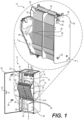
- FIG. 1 is a schematic perspective view of an example splice enclosure 10 including an example cabinet 12 and an example splice tray assembly 14.
- the cabinet 12 defines an interior volume 16 and includes a rear wall 18, a first side wall 20 coupled to the rear wall 18, and a second side wall 22 coupled to the rear wall 18 and spaced from the first side wall 20.
- the example cabinet 12 shown in FIG. 1 also includes a lower wall 24 coupled to the first side wall 20, the second side wall 22, and/or the rear wall 18.
- the lower wall 24 may include knock-outs and/or other structures (e.g., openings) for mounting the cabinet 12 to a support (e.g., a floor or platform) and/or to provide one or more entry points for one of more cables to pass from exterior to the cabinet 12 to the interior volume 16 of the cabinet 12.
- the example cabinet 12 also includes a front panel 26 coupled to the first side wall 20 and configured to pivot with respect to the first side wall 20.
- the front panel 26 may serve as a door to gain access to the interior volume 16 of the cabinet 12 and may be mounted on hinges 28 to support the front panel 26 and permit pivoting of the front panel 26 relative to the remainder of the cabinet 12.
- the example cabinet 12 also includes an upper wall 30 coupled to one or more of the first side wall 20, the second side wall 22, and/or the rear wall 18.
- the upper wall 30, or at least a portion thereof may be removably coupled to the first side wall 20, the second side wall 22, and/or the rear wall 18, which may render it relatively easier for a technician installing the cables to access the cables as they are routed into the cabinet 12.
- the upper wall 30 may include knock-outs and/or other structures (e.g., openings) for providing one or more entry points for one of more cables to pass from exterior to the cabinet 12 to the interior volume 16 of the cabinet 12.
- the cabinet 12 may define a longitudinal axis X extending in a direction substantially parallel to planes in which the rear wall 18 and at least one of the first wall 20 or the second wall 22 lie.
- the cabinet 12 may also include a latch 32 coupled to the front panel 26 and a catch 34 coupled to the second wall 22 and configured to selectively secure the front panel 26 in the closed position.
- the front panel 26 may also include one or more brackets (e.g., brackets 36 and 38) coupled to an interior side of the front panel 26 and configured to facilitate hanging therefrom cables, splice trays associated with the splice tray assembly 14, and/or other parts related to the splice enclosure 10, which may improve the ease with which a technician may perform splicing or other service-related operations.
- the bracket 36 may be configured to engage the upper wall 30.
- the splice enclosure 10 may include one or more mounting brackets (e.g., coupled to rear wall 18) configured to couple the splice enclosure 10 to a support, such as, for example, a rack or a wall or support of the building in which the splice enclosure 10 is present.
- a support such as, for example, a rack or a wall or support of the building in which the splice enclosure 10 is present.
- the splice enclosure 10 may also include a divider plate 40 in a lower portion of the cabinet 12 to assist with organizing the optical fibers being spliced.
- Some examples of the splice enclosure 10 may also include one or more brackets 42 coupled to the cabinet 12 at an end of the cabinet 12 remote from the lower wall 24.
- the one or more brackets 42 may be coupled to the rear wall 18 via at least one of one or more fasteners, welding, or adhesives.
- the one or more brackets 42 may each include one or more apertures configured to receive a boss associated with a clip configured to be coupled to at least one cable (e.g., via a cable-tie) and the respective bracket 42, for example, as explained in more detail herein.
- the example splice enclosure 12 includes a splice tray assembly 14.
- the splice tray assembly 14 includes a splice tray housing 44 pivotally coupled to the cabinet 12 and a plurality of splice trays 46 coupled to the splice tray housing 44 (e.g., pivotally coupled to the splice tray housing 44, for example, as shown in FIG. 2 ) and configured to provide a space for receipt of a plurality of spliced optical fibers of a plurality of cables.
- the splice tray housing 44 in the example shown in FIG.
- splice tray housing 44 may be pivotally coupled to the cabinet 12, such that the splice tray housing 44 pivots about a housing pivot axis P extending in a direction substantially perpendicular with respect to the longitudinal axis X, for example, substantially parallel with respect to a plane in which the rear wall 18 lies. Such pivoting may render it relatively easier for a technician to gain access to one or more of the splice trays 46.
- some examples of the splice enclosure 10 may include one or more support rails 48 coupled to the interior of each of the first side wall 20 and the second side wall 22 and extending substantially in the direction of the longitudinal axis X .
- the support rails 48 may be configured to assist with support of the splice tray housing 44 and splice trays 46 within the cabinet 12.
- Housing support brackets may be coupled to the interior of each of the first side wall 20 and the second side wall 22.
- the housing support brackets may include a recess, and, as shown in FIG. 1 , the splice tray housing 44 may include a pivot pin 50 at each of opposite ends of the splice tray housing 44.
- the pivot pins 50 may be received in respective the recesses of the support brackets, for example, such that the splice tray housing 44 is pivotally supported with respect to the cabinet 12 and is able to be pivoted from an upright position to a pivoted position, for example, as shown in FIG. 1 .
- the cabinet 12 and the splice tray assembly 14 define a passage between the rear wall 18 of the cabinet 12 and the splice tray assembly 14 configured for passage of a plurality of cables therethrough.
- the splice tray housing 14 is releasably coupled to the cabinet 12 for separation of the splice tray housing 14 and splice trays 46 from the cabinet 12, for example, to provide access to the rear part of the cabinet 12 (e.g., the part of the cabinet 12 behind the splice tray housing 14).
- the splice tray housing 14 may be lifted out of the recesses in the support brackets.
- the splice tray housing 44 may include a first end wall 52 and a second end wall 54 opposite the first end wall 52.
- each of the first and second end walls 52 and 54 includes a pivot pin 50 mounted thereon at a lower portion of the respective first and second end walls 52 and 54 and at a portion of the first and second end walls 52 and 54 closer to the front of the cabinet 12 (e.g., opposite the rear wall 18) when the splice tray assembly 14 is mounted in the cabinet 12. This may result in biasing the splice tray assembly 14 from pivoting outward toward the technician, unless the technician pulls an upper end of the splice tray assembly 14 outward.
- a latch may be provided on the splice tray assembly 14 and/or the first and second side walls 20 and 22 of the cabinet 12 to selectively the secure the splice tray assembly 14 in the upright position.
- Some examples may also include a pivot limiting assembly configured to prevent the splice tray assembly 14 from pivoting past a predetermined angular displacement.
- a limiting bracket 56 may be provided on one or more of the exterior surface of the first end wall 52 or the second end wall 54 for cooperating with a limiting member coupled to the cabinet 12 to prevent the splice tray assembly 14 from pivoting past a predetermined angular displacement.
- the limiting member may be a cable, a hook, a strut, etc., configured to be received in a hole 58 in the limiting bracket 56 and limit the angular displacement.
- one or more of the plurality of splice trays 46 may be pivotally coupled to the splice tray housing 44, for example, such that the one or more splice trays 46 pivots relative to the splice tray housing 44 about a splice tray pivot axis 1 extending in a direction substantially perpendicular with respect to the longitudinal axis X of the cabinet 12 and substantially parallel with respect to the plane in which the rear wall 18 lies. Pivoting of the splices trays 46 may render it relatively easier for a technician to splice the optical fibers in the splice trays 46 and/or to check the quality of the splice or splices.
- FIGS. 1 and 2 includes a retainer 60 extending between the first end wall 52 and the second end wall 54 configured to prevent one or more or the splice trays 46 from pivoting outward relative to the splice tray housing 44.
- opposite ends of the retainer 60 may be coupled to the first and second end walls 52 and 54 of the splice tray housing 44, so that the retainer 60 may be pivoted between a first position preventing the splice trays 46 from pivoting to a second position permitting the splice trays 46 to pivot.
- the lower portion of FIG. 1 shows the retainer 60 in the first position, preventing the splice trays 46 from pivoting relative to the splice tray housing 44, and the upper portion of FIG.
- the example splice tray housing 44 also includes a divider panel 62 separating some of the splice trays 46 from others of the splice trays 46 (e.g., a first half of the splice trays 46 from a second half of the splice trays 46). This may render it relatively easier for the technician to organize the cables, optical fibers, and/or splices.
- the splice trays 46 may be provided for providing a space for receipt of a plurality of spliced optical fibers of a plurality of cables.
- the splice trays 46 may include a tray base 64 including a substantially planar base panel 66 having an entry end 68 and a remote end 70 spaced from the entry end 68.
- the base panel 66 may define a perimeter 72 and a flange 74 associated with the perimeter 72 of the base panel 66 and extending outward from the base panel 66.
- the splice holder 76 may include a holder base 78 removably coupled to the tray base 64, and a plurality of ribs 80 associated with the holder base 82 and defining a plurality of recesses 82 configured to receive at least one pair of spliced optical fibers.
- the recesses 82 may be configured to receive splices of 40 millimeters and/or 60 millimeters. In some examples, one or more of the recesses 82 may be configured to receive splices of other sizes. As shown in FIGS.
- the splice trays 46 may also include a cover 84 removably coupled to at least one of the tray base 64 or the splice holder 76 and substantially enclosing the splice holder 76 between the tray base 64 and the cover 84.
- the cover 84 may be translucent or transparent. Such examples may permit a technician to view the splices without removing the cover 84, for example, to check the quality of the splices using known visual splice-checking techniques.
- the splice tray 46 may also include a plurality of resilient hooks 86 extending outward from the base panel 66 and removably coupling the splice holder 76 to the tray base 64.
- This example configuration may permit the splice holder 76 to be separated from the splice tray 46 to facilitate placement of splices in the recesses 82, after which the splice holder 76 may be reengaged with the tray base 64 via the hooks 86.
- the tray base 64 of the splice tray 46 may include a plurality of apertures 88 at the entry end 68 configured to facilitate coupling of at least one cable and/or optical fiber to the splice tray 46.
- a cable-tie may be wrapped partially around a cable or optical fiber and threaded through two (or more) of the apertures 88, after which the cable-tie may be tightened to secure the cable and/or optical fiber to the entry end 68 of the splice tray 46.
- the splice trays 46 may also include a plurality of retainer tabs 90 configured to retain and/or assist with organizing at least one optical fiber.
- the retainer tabs 90 may each extend outward from the tray base 64 to a remote tab end 92.
- a retainer flange 94 may extend from the remote tab end 92 in a direction substantially parallel with respect to the base panel 66. The retainer tabs 90 may assist with organizing the cables and/or optical fibers within the splice tray 46.
- the cables may be ribbon cables that are substantially flat, including a plurality of optical fibers held in a side-by-side relationship, and the retainer tabs 90 may be configured such that a plurality of ribbon cables may be retained in an overlapping manner by the retainer tabs 90.
- the ribbon cables may be "stacked" such that they lie flat and on top of (or adjacent) one another when received in the retainer tabs 90.
- the tray base 64 may define a storage zone 96 between the splice holder 76 and the remote end 70 of the tray base 64.
- the storage zone 96 may be configured to provide space for receiving excess length of at least one cable and/or optical fiber.
- the excess length of cable and/or optical fiber may be looped, for example, in a coiled manner, and placed in the storage zone 96.
- the ribbon cables may be overlapped and stored in a looped and/or coiled manner in the storage zone 96.
- the example splice tray 48 shown in FIGS. 2-5 also includes a plurality of cover tabs 98 extending from the tray base 64 and configured to removably couple the cover 84 to the tray base 64.
- the cover tabs 98 may facilitate access to the interior of the splice tray 46 and thereafter may be used to secure the cover 84 to the tray base 64.
- the splice tray 46 may include a flexible latch 100 extending from an outer surface of the flange 74 of the tray base 64 (e.g., at the remote end 70 of the tray base 64).
- the latch 100 may be configured to selectively prevent and allow the splice tray 46 to pivot with respect to the splice tray assembly 14 to which the splice tray 46 is coupled, for example, when the retainer 60 is moved to the second position (see e.g., FIG. 2 ), as explained previously herein.
- the splice tray 46 is in the unpivoted position (see, e.g., the lower part of FIG.
- the latch 100 may engage a latch catch 102, which is schematically shown in FIG. 2 .
- an extension 104 of the latch 100 may be flexed toward the flange 74 to disengage the latch 100 from the latch catch 102, such that the splice tray 46 may be pivoted with respect to the splice tray housing 44, for example, as shown in FIG. 2 .
- the splice tray 46 may include a pivot recess 106 defined by the tray base 64 and configured to cooperate with a pivot support 108 of a splice tray assembly 14 (e.g., of the splice tray housing 44) to facilitate pivoting of the splice tray 46 with respect to the splice tray assembly 14.
- the pivot recess 106 may form a semi-circular bearing surface 110 (see FIG. 3 ) for rotation relative to the pivot support 108.
- Some examples may also include a pivot stop 112 associated with the pivot recess 106 and configured to limit a pivot angle through which the splice tray 46 pivots relative to the splice tray assembly 14 (e.g., the splice tray housing 44).
- the pivot stop 112 may include an abutment surface 114 (see Fig. 3 ) located adjacent the pivot recess 106 and configured to engage a portion of the pivot support 108, thereby preventing the splice tray 46 from pivoting relative to the splice tray housing 44 beyond a predetermined angle of displacement.
- one or more transition tubes 116 may be provided for securing the cable and/or optical fibers to the splice tray 46 at a point in which the cable and/or optical fibers enter the splice tray 46.
- the transition tube 116 may receive a cable and/or optical fibers, and the transition tube 116 may be coupled to the entry end 68 of the splice tray 46, for example, as shown in FIG. 5 .
- one or more cable-ties 118 may be used to secure the transition tubes 116 to the entry end 68 of the splice tray 46 by being wrapped partially around the transition tube 116, passed through two or more of the apertures 88 in the entry end 68 of the tray base 64, and tightened about the transition tube 116.
- the transition tube 116 may include an elongated tubular member 120 defining an internal passage 122, which in some examples, may define a substantially rectangular cross-section for receipt of at least one ribbon cable (e.g., a plurality of overlapping ribbon cables). It is contemplated that the internal passage 122, in some examples, may define a cross-section other than rectangular, such as, for example, a circular or semi-circular cross-section for receipt of cables and/or optical fibers that are not ribbon cables. As shown in FIGS. 7 and 8 , some examples of the transition tube 116 may include a mating section 124 presenting a substantially planar surface 126 for abutting the entry end 68 of the tray base 64.
- the entry end 68 of the tray base 64 may present a substantially planar surface 128, and the substantially planar surface 126 of the mating section 124 of the transition tube 116 may face the substantially planar surface 128 of entry end 68, and thus, when the transition tube 116 is secured against the tray base 64, rotation of the transition tube 116 and the cables and/or optical fibers passing through the transition tube 116 is substantially prevented.
- the transition tube 116 may include at least one recess 130 (e.g., a circumferential recess) extending at least partially around an outer surface of the transition tube 116 and configured to receive a cable-tie 118 for coupling the transition tube 116 to the tray base 64 via the apertures 88 at the entry end 68 of the tray base 64.
- Some examples of the recesses 130 may assist with preventing the transition tube 116 from displacing longitudinally relative to the splice tray 46 once the transition tube 116 is secured to the tray base 64 of the splice tray 46.
- the transition tube 116 may also include a longitudinal slot 132 extending at least partially the length of the transition tube 116 and configured to receive a cable (e.g., a ribbon cable) therethrough.
- the slot 132 may extend the length of the transition tube 116, and a ribbon cable may be inserted into the transition tube 116 via the slot 132, for example, without the need to pass the end of the ribbon cable into one end of the transition tube 116.
- a technician may slide the transition tube 116 onto one or more ribbon cables via the slot 132.
- the slot 132 includes chamfered edges 134 configured to render it relatively easier to insert a ribbon cable into the slot 132.
- the slot 132 may include tapered ends 136 at at least one end of the transition tube 116 (e.g., the end including the mating section 124) to facilitate insertion of ribbon cables into the slot 132.
- FIGS. 9 and 10 show an example anti-twist clip 138 configured to be coupled to the tray base 64 and prevent ribbon cable from twisting.
- FIG. 5 shows example anti-twist clips 138 coupled to the splice tray 46 via example resilient clip retainers 140 associated with (e.g., coupled to) the base tray 64.
- the anti-twist clips 138 may be configured to receive a plurality of ribbon cables in an overlapping relationship and may prevent the ribbon cables from becoming twisted in the splice tray 46.
- some examples of the anti-twist clips 138 may include a tubular member 142 defining an internal passage 144, which in some examples, may define a substantially rectangular cross-section for receipt of at least one ribbon cable (e.g., a plurality of overlapping ribbon cables). It is contemplated that the internal passage 144, in some examples, may define a cross-section other than rectangular, such as, for example, a circular or semi-circular cross-section for receipt of cables and/or optical fibers that are not ribbon cables. As shown in FIGS. 9 and 10 , some examples of the anti-twist clips 138 may include a pair of substantially planar surfaces 146 on opposite sides of the tubular member 142.
- the surfaces 146 may provide the anti-twist clips 138 with a relatively a lower profile for fitting in the interior of the splice trays 46 and may present surfaces for abutting the base panel 66 of the tray base 64 and for engagement with the respective clip retainers 140 when installed in the splice tray 46.
- the anti-twist clips 138 may be configured for ease of engagement and disengagement with the splice tray 46, for example, so that a technician may be able to insert the cables and/or optical fibers into the internal passage 144 of the anti-twist clip 138 with the anti-twist clip 138 separated from the splice tray 46, and thereafter engage the anti-twist clip 138 with the clip retainers 140 before installing the cover 84 onto the splice tray 46.
- the tray base 64 may present a substantially planar surface 128, and one of the substantially planar surfaces 146 of the anti-twist clip 138 may face the substantially planar surface 128, and thus, when the anti- twist clip 138 is secured against the tray base 64, rotation of the anti-twist clip 138 and/or the cables and/or optical fibers passing through the anti-twist clip 138 is substantially prevented.
- the anti-twist clip 138 may include a longitudinal slot 148 extending at least partially the length of the anti-twist clip 138 (e.g., the entire length) and configured to receive a ribbon cable therethrough.
- the slot 148 may extend the length of the anti-twist clip 138, and a ribbon cable may be inserted into the anti-twist clip 138 via the slot 148, for example, without the need to pass the end of the ribbon cable into one end of the anti-twist clip 138.
- a technician may slide the anti- twist clip 138 onto one or more ribbon cables via the slot 148.
- the slot 148 includes chamfered edges 150 configured to render it relatively easier to insert a ribbon cable into the slot 148.
- Some examples of the slot 148 may include tapered ends 152 at at least one end of the anti-twist clip 138 to facilitate insertion of ribbon cables into the slot 148.
- FIGS. 11-13 show another example of an anti-twist clip 138.
- the example shown in FIGS. 11-13 includes a first mating part 154, a second mating part 156 configured to engage the first mating part 154, and a flexible tie member 158 coupled to both the first mating part 154 and the second mating part 156 and configured to permit the first and second mating halves 154 and 156 to remain coupled to one another when not engaged with one another.
- the first and second mating halves 154 and 156, when engaged with one another are configured to present an anti-twist clip 138 similar in function to the example anti-twist clip 138 shown in FIGS. 9 and 10 .
- the anti-twist clip 138 is configured to be coupled to the tray base 64 and prevent ribbon cable from twisting.
- the anti-twist clip 138 shown in FIGS. 11-13 may be coupled to the splice tray 46 via the example resilient clip retainers 140 associated with (e.g., coupled to) the base tray 64.
- the anti-twist clips 138 may be configured to receive a plurality of ribbon cables 160 in an overlapping relationship and may prevent the ribbon cables from becoming twisted in the splice tray 46, for example, as shown in FIG. 13 .
- the example anti-twist clip 138 shown in FIGS. 11-13 may be configured to form a tubular member 162 defining an internal passage 164, which, in some examples, may define a substantially rectangular cross-section for receipt of at least one ribbon cable (e.g., a plurality of overlapping ribbon cables). It is contemplated that the internal passage 164, in some examples, may define a cross-section other than rectangular, such as, for example, a circular or semi-circular cross-section for receipt of cables and/or optical fibers that are not ribbon cables. As shown in FIG. 13 , the example anti-twist clip 138 shown in FIGS. 11-13 may include a pair of substantially planar surfaces 166 on opposite sides of the tubular member 162.
- the surfaces 166 may provide the anti-twist clips 138 with a relatively a lower profile for fitting in the interior of the splice trays 46 and may present surfaces for abutting the base panel 66 of the tray base 64 and for engagement with the respective clip retainers 140 when installed in the splice tray 46.
- the anti-twist clips 138 in the example shown in FIGS.
- 11-13 may be configured for ease of engagement and disengagement with the splice tray 46, for example, so that a technician may be able to insert the cables and/or optical fibers into the internal passage 144 of the anti-twist clip 138 with the anti-twist clip 138 separated from the splice tray 46, fold over the tie member 158 to engage the first and second mating halves 154 and 156 with one another, and thereafter engage the anti-twist clip 136 with the clip retainers 140 before installing the cover 84 onto the splice tray 46.
- the tray base 64 may present a substantially planar surface 128, and one of the substantially planar surfaces 166 of the anti-twist clip 138 may face the substantially planar surface 128, and thus, when the anti-twist clip 138 is secured against the tray base 64, rotation of the anti-twist clip 138 and/or the cables and/or optical fibers passing through the anti-twist clip 138 is substantially prevented.
- the example anti-twist clip 138 shown in FIGS. 11-13 may include a catch 168 on the first mating part 154 configured to engage a recess 170 on the second mating part 156, for example, as shown in FIG. 11 .
- a first portion 172 of the first mating part 154 and a first portion 174 of the second mating part 156 may be formed by a first material.
- a second portion 176 of the first mating part 154 and a second portion 178 of the second mating part 156 may be formed by a second material.
- the second material may also form the tie member 158.
- the second material is relatively more flexible and/or elastic than the first material.
- the second portions 176 and 178 of the respective first and second mating halves 154 and 156 may be integrally formed with the tie member 158.
Landscapes
- Physics & Mathematics (AREA)
- General Physics & Mathematics (AREA)
- Optics & Photonics (AREA)
- Engineering & Computer Science (AREA)
- Computer Networks & Wireless Communication (AREA)
- Light Guides In General And Applications Therefor (AREA)
- Mechanical Coupling Of Light Guides (AREA)
Description
- This application is a continuation of International Application No.
PCT/US18/56266, filed on October 17, 2018 , which claims the benefit of priority toU.S. Application No. 62/573,381, filed on October 17, 2017 - This disclosure relates to splice trays for optical fibers, and more particularly, to splice trays for providing a space for receipt of a plurality of spliced optical fibers.
- It is often desirable to splice the ends of one or more optical fibers of a first cable to the ends of one or more optical fibers of a second cable. For example, cables including optical fibers may be used to communicate information from a source to one or more devices. Some such cables may be routed through the environment to a building and enter the building through one or more ducts. The interior of the building may include an internal communication network including one or more cables including optical fibers. The optical fibers from exterior to the building may be spliced to optical fibers in the interior of the building to link the communication from the source to the communication network in the interior of the building.
- A splice enclosure may be provided for providing a space for receipt of spliced optical fibers of many cables. For example, a splice tray may be provided for receiving spliced optical fibers, and the splice tray may be received in the splice enclosure. Splicing the optical fibers to one another is often tedious and time consuming, often resulting in significant expense. In addition, as data communication increases and the number of optical fibers grows to accommodate the increase, the capacity of splice enclosures and splice trays may be insufficient to accommodate the splicing of additional optical fibers in an efficient manner. Moreover, as more spliced optical fibers are received in splice trays due to the increase in optical fibers, it may be difficult to perform the splicing and place the spliced fibers into the splice trays in an efficient manner.
- Some examples described herein may address one or more possible drawbacks associated with increasing the additional optical fibers and placing the associated increased number of spliced fibers in splice trays.
-
WO2009/048795 A1 discloses a splice holder which includes an ejector to facilitate the removal of a fiber optic splice from the splice holder. The splice holder includes a base having a first side and a second side and a plurality of partitions extending from the first side of the base to releasably hold a fiber optic splice. The ejector may be disposed in the base of the splice holder adjacent to at least one of the partitions. The ejector allows removal of a fiber optic splice without disturbing any of the other splices held by the splice holder. The splice holder may be used in a splice tray having a cut-out area in the splicing section of the splice tray. Trunion pins may extend from a backside of the splice tray which can then engage in a snug fit or a pivot fit with corresponding receptacles in a support structure in the housing, closure or enclosure. -
US 2018/284379 A1 ,US 2009/290844 A1 andUS 5572617 A disclose splice trays comprising removably coupled splice holders comprising a plurality of ribs suitable to hold spliced optical fibers. -
WO 2004/034116 A1 ,US 5402515 A andUS 5946440 A disclose splice trays which pivot outwards in a plane defined by the tray base. - The invention is defined by the independent claim to which reference should now be made. Advantageous features are set forth in the dependent claims.
-
-
FIG. 1 is a schematic perspective view of an example splice enclosure including an example cabinet and an example splice tray assembly. -
FIG. 2 is a schematic perspective view of an example splice tray pivoted relative to an example splice tray assembly support. -
FIG. 3 is a schematic perspective view of an example splice tray shown from an example entry end without a cover. -
FIG. 4 is a schematic perspective view of the example splice tray shown inFIG. 3 from an end opposite the entry end. -
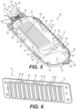
FIG. 5 is a schematic perspective view of the example splice tray shown inFIG. 3 from the end opposite the entry end with a cover. -
FIG. 6 is a schematic perspective view of an example splice holder. -
FIG. 7 is a schematic perspective view from one side of an example transition tube. -
FIG. 8 is a schematic perspective view from another side of the example transition tube shown inFIG. 7 . -
FIG. 9 is a schematic perspective view from one side of an example anti-twist clip. -
FIG. 10 is a schematic perspective view from another side of the anti-twist clip shown inFIG. 9 . -
FIG. 11 is a schematic perspective view of another example anti-twist clip shown from one side in an unassembled condition. -
FIG. 12 is a schematic perspective view of the example anti-twist clip shown inFIG. 11 from another side and in an unassembled condition. -
FIG. 13 is a schematic side section view of the example anti-twist clip shown inFIGS. 11 and 12 shown in an assembled condition surrounding a plurality of example optical fibers. - Reference will now be made in detail to embodiments, examples of which are illustrated in the accompanying drawings. Whenever possible, the same reference numbers are used throughout the drawings to refer to the same or like parts.
- This disclosure is generally directed to splice trays for optical fibers and to splice trays for providing a space for receipt of a plurality of spliced optical fibers, and related methods. For example, cables including optical fibers may be used to communicate information from a communication source to one or more devices. Such cables may be routed through the environment to a building or between buildings (e.g., data center buildings) via ducts and enter a building through one or more ducts. As noted above, the interior of the building may include an internal communication network including one or more cables including optical fibers. The optical fibers from exterior to the building may be spliced to optical fibers in the interior of the building to link the communication from a communication source to the communication network in the interior of the building. In some examples, the cables exterior to the building may have different requirements than requirements of the cables inside the building. For example, cables inside a building may need to comply with fire codes and/or other regulations, while cables exterior to the building may not need to comply with such codes and/or other regulations.
- A splice enclosure may be provided for providing a space for receipt of many spliced optical fibers of many cables. For example, a splice tray may be provided for receiving spliced optical fibers, and the splice tray may be received in the splice enclosure.
- In some examples, the splice tray and related methods described herein may be configured to provide space for accommodating (e.g., storing and/or protecting) splicing of one or more higher fiber-count cables, such as, for example, 1728 fiber-count cables, 3456 fiber-count cables, and/or 6912 fiber-count cables. In some examples, one or more of the cables may be ribbon cables, for example, having optical fibers arranged adjacent to other optical fibers of the cables, such that the adjacent optical fibers are arranged substantially along a line forming a substantially flat ribbon including a plurality of optical fibers. In some examples, the cables may not be ribbon cables. Some examples of the splice trays described herein may accommodate the splicing of additional optical fibers in an efficient manner relative to conventional enclosures. Splicing for different purposes and/or different types of optical fibers is/are contemplated.
-
FIG. 1 is a schematic perspective view of an example splice enclosure 10 including anexample cabinet 12 and an examplesplice tray assembly 14. In the example shown, thecabinet 12 defines an interior volume 16 and includes arear wall 18, afirst side wall 20 coupled to therear wall 18, and asecond side wall 22 coupled to therear wall 18 and spaced from thefirst side wall 20. Theexample cabinet 12 shown inFIG. 1 also includes alower wall 24 coupled to thefirst side wall 20, thesecond side wall 22, and/or therear wall 18. In some examples, thelower wall 24 may include knock-outs and/or other structures (e.g., openings) for mounting thecabinet 12 to a support (e.g., a floor or platform) and/or to provide one or more entry points for one of more cables to pass from exterior to thecabinet 12 to the interior volume 16 of thecabinet 12. Theexample cabinet 12 also includes afront panel 26 coupled to thefirst side wall 20 and configured to pivot with respect to thefirst side wall 20. For example, thefront panel 26 may serve as a door to gain access to the interior volume 16 of thecabinet 12 and may be mounted on hinges 28 to support thefront panel 26 and permit pivoting of thefront panel 26 relative to the remainder of thecabinet 12. Theexample cabinet 12 also includes an upper wall 30 coupled to one or more of thefirst side wall 20, thesecond side wall 22, and/or therear wall 18. In some examples, the upper wall 30, or at least a portion thereof, may be removably coupled to thefirst side wall 20, thesecond side wall 22, and/or therear wall 18, which may render it relatively easier for a technician installing the cables to access the cables as they are routed into thecabinet 12. In some examples, the upper wall 30 may include knock-outs and/or other structures (e.g., openings) for providing one or more entry points for one of more cables to pass from exterior to thecabinet 12 to the interior volume 16 of thecabinet 12. As shown, thecabinet 12 may define a longitudinal axis X extending in a direction substantially parallel to planes in which therear wall 18 and at least one of thefirst wall 20 or thesecond wall 22 lie. Although the terms "rear," "side," "front," "lower," and "upper" have been used for clarity and describing relative relationships among parts, the use of these terms is not intended to be absolute. - As shown in
FIG. 1 , thecabinet 12 may also include alatch 32 coupled to thefront panel 26 and a catch 34 coupled to thesecond wall 22 and configured to selectively secure thefront panel 26 in the closed position. In the example shown, thefront panel 26 may also include one or more brackets (e.g., brackets 36 and 38) coupled to an interior side of thefront panel 26 and configured to facilitate hanging therefrom cables, splice trays associated with thesplice tray assembly 14, and/or other parts related to the splice enclosure 10, which may improve the ease with which a technician may perform splicing or other service-related operations. In some examples, the bracket 36 may be configured to engage the upper wall 30. Some examples of the splice enclosure 10 may include one or more mounting brackets (e.g., coupled to rear wall 18) configured to couple the splice enclosure 10 to a support, such as, for example, a rack or a wall or support of the building in which the splice enclosure 10 is present. - As described in more detail herein, the splice enclosure 10 may also include a
divider plate 40 in a lower portion of thecabinet 12 to assist with organizing the optical fibers being spliced. Some examples of the splice enclosure 10 may also include one or more brackets 42 coupled to thecabinet 12 at an end of thecabinet 12 remote from thelower wall 24. For example, the one or more brackets 42 may be coupled to therear wall 18 via at least one of one or more fasteners, welding, or adhesives. In some examples, the one or more brackets 42 may each include one or more apertures configured to receive a boss associated with a clip configured to be coupled to at least one cable (e.g., via a cable-tie) and the respective bracket 42, for example, as explained in more detail herein. - As shown in
FIG. 1 , theexample splice enclosure 12 includes asplice tray assembly 14. In the examples shown, thesplice tray assembly 14 includes asplice tray housing 44 pivotally coupled to thecabinet 12 and a plurality ofsplice trays 46 coupled to the splice tray housing 44 (e.g., pivotally coupled to thesplice tray housing 44, for example, as shown inFIG. 2 ) and configured to provide a space for receipt of a plurality of spliced optical fibers of a plurality of cables. For example, thesplice tray housing 44, in the example shown inFIG. 1 , may be pivotally coupled to thecabinet 12, such that thesplice tray housing 44 pivots about a housing pivot axis P extending in a direction substantially perpendicular with respect to the longitudinal axis X, for example, substantially parallel with respect to a plane in which therear wall 18 lies. Such pivoting may render it relatively easier for a technician to gain access to one or more of thesplice trays 46. - As shown in
FIG. 1 , some examples of the splice enclosure 10 may include one or more support rails 48 coupled to the interior of each of thefirst side wall 20 and thesecond side wall 22 and extending substantially in the direction of the longitudinal axis X. The support rails 48 may be configured to assist with support of thesplice tray housing 44 andsplice trays 46 within thecabinet 12. Housing support brackets may be coupled to the interior of each of thefirst side wall 20 and thesecond side wall 22. The housing support brackets may include a recess, and, as shown inFIG. 1 , thesplice tray housing 44 may include apivot pin 50 at each of opposite ends of thesplice tray housing 44. The pivot pins 50 may be received in respective the recesses of the support brackets, for example, such that thesplice tray housing 44 is pivotally supported with respect to thecabinet 12 and is able to be pivoted from an upright position to a pivoted position, for example, as shown inFIG. 1 . In some examples, thecabinet 12 and thesplice tray assembly 14 define a passage between therear wall 18 of thecabinet 12 and thesplice tray assembly 14 configured for passage of a plurality of cables therethrough. In some examples, thesplice tray housing 14 is releasably coupled to thecabinet 12 for separation of thesplice tray housing 14 andsplice trays 46 from thecabinet 12, for example, to provide access to the rear part of the cabinet 12 (e.g., the part of thecabinet 12 behind the splice tray housing 14). For example, thesplice tray housing 14 may be lifted out of the recesses in the support brackets. - As shown in
FIG. 1 , thesplice tray housing 44 may include afirst end wall 52 and a second end wall 54 opposite thefirst end wall 52. In the example shown inFIG. 1 , each of the first andsecond end walls 52 and 54 includes apivot pin 50 mounted thereon at a lower portion of the respective first andsecond end walls 52 and 54 and at a portion of the first andsecond end walls 52 and 54 closer to the front of the cabinet 12 (e.g., opposite the rear wall 18) when thesplice tray assembly 14 is mounted in thecabinet 12. This may result in biasing thesplice tray assembly 14 from pivoting outward toward the technician, unless the technician pulls an upper end of thesplice tray assembly 14 outward. In some examples, a latch may be provided on thesplice tray assembly 14 and/or the first andsecond side walls cabinet 12 to selectively the secure thesplice tray assembly 14 in the upright position. Some examples may also include a pivot limiting assembly configured to prevent thesplice tray assembly 14 from pivoting past a predetermined angular displacement. For example, as shown inFIG. 1 , a limitingbracket 56 may be provided on one or more of the exterior surface of thefirst end wall 52 or the second end wall 54 for cooperating with a limiting member coupled to thecabinet 12 to prevent thesplice tray assembly 14 from pivoting past a predetermined angular displacement. The limiting member may be a cable, a hook, a strut, etc., configured to be received in a hole 58 in the limitingbracket 56 and limit the angular displacement. - As shown in
FIGS. 1 and2 , in some examples, one or more of the plurality ofsplice trays 46 may be pivotally coupled to thesplice tray housing 44, for example, such that the one ormore splice trays 46 pivots relative to thesplice tray housing 44 about a splicetray pivot axis 1 extending in a direction substantially perpendicular with respect to the longitudinal axis X of thecabinet 12 and substantially parallel with respect to the plane in which therear wall 18 lies. Pivoting of thesplices trays 46 may render it relatively easier for a technician to splice the optical fibers in thesplice trays 46 and/or to check the quality of the splice or splices. The example shown inFIGS. 1 and2 includes aretainer 60 extending between thefirst end wall 52 and the second end wall 54 configured to prevent one or more or thesplice trays 46 from pivoting outward relative to thesplice tray housing 44. For example, opposite ends of theretainer 60 may be coupled to the first andsecond end walls 52 and 54 of thesplice tray housing 44, so that theretainer 60 may be pivoted between a first position preventing thesplice trays 46 from pivoting to a second position permitting thesplice trays 46 to pivot. For example, the lower portion ofFIG. 1 shows theretainer 60 in the first position, preventing thesplice trays 46 from pivoting relative to thesplice tray housing 44, and the upper portion ofFIG. 1 (andFIG. 2 ) shows theretainer 60 in the second position, allowing thesplice trays 46 to pivot relative to thesplice tray housing 44. As shown inFIG. 1 , the examplesplice tray housing 44 also includes a divider panel 62 separating some of thesplice trays 46 from others of the splice trays 46 (e.g., a first half of thesplice trays 46 from a second half of the splice trays 46). This may render it relatively easier for the technician to organize the cables, optical fibers, and/or splices. - As shown in
FIGS. 2-5 , one or more of thesplice trays 46 may be provided for providing a space for receipt of a plurality of spliced optical fibers of a plurality of cables. For example, as shown inFIG. 2 , thesplice trays 46 may include atray base 64 including a substantiallyplanar base panel 66 having anentry end 68 and aremote end 70 spaced from theentry end 68. Thebase panel 66 may define aperimeter 72 and aflange 74 associated with theperimeter 72 of thebase panel 66 and extending outward from thebase panel 66. Theexample splice tray 46 shown inFIGS. 2-5 also includes asplice holder 76 configured to hold a plurality of spliced optical fibers. As shown inFIG. 6 , in some examples, thesplice holder 76 may include aholder base 78 removably coupled to thetray base 64, and a plurality ofribs 80 associated with theholder base 82 and defining a plurality ofrecesses 82 configured to receive at least one pair of spliced optical fibers. In some examples, therecesses 82 may be configured to receive splices of 40 millimeters and/or 60 millimeters. In some examples, one or more of therecesses 82 may be configured to receive splices of other sizes. As shown inFIGS. 2 and5 , thesplice trays 46 may also include acover 84 removably coupled to at least one of thetray base 64 or thesplice holder 76 and substantially enclosing thesplice holder 76 between thetray base 64 and thecover 84. In some examples, thecover 84 may be translucent or transparent. Such examples may permit a technician to view the splices without removing thecover 84, for example, to check the quality of the splices using known visual splice-checking techniques. - As shown in
FIG. 3 , thesplice tray 46 may also include a plurality ofresilient hooks 86 extending outward from thebase panel 66 and removably coupling thesplice holder 76 to thetray base 64. This example configuration may permit thesplice holder 76 to be separated from thesplice tray 46 to facilitate placement of splices in therecesses 82, after which thesplice holder 76 may be reengaged with thetray base 64 via thehooks 86. - In some examples, the
tray base 64 of thesplice tray 46 may include a plurality ofapertures 88 at theentry end 68 configured to facilitate coupling of at least one cable and/or optical fiber to thesplice tray 46. For example, a cable-tie may be wrapped partially around a cable or optical fiber and threaded through two (or more) of theapertures 88, after which the cable-tie may be tightened to secure the cable and/or optical fiber to theentry end 68 of thesplice tray 46. - As shown in
FIGS. 2-5 , thesplice trays 46 may also include a plurality ofretainer tabs 90 configured to retain and/or assist with organizing at least one optical fiber. For example, theretainer tabs 90 may each extend outward from thetray base 64 to aremote tab end 92. In some examples, aretainer flange 94 may extend from theremote tab end 92 in a direction substantially parallel with respect to thebase panel 66. Theretainer tabs 90 may assist with organizing the cables and/or optical fibers within thesplice tray 46. For example, the cables may be ribbon cables that are substantially flat, including a plurality of optical fibers held in a side-by-side relationship, and theretainer tabs 90 may be configured such that a plurality of ribbon cables may be retained in an overlapping manner by theretainer tabs 90. For example, the ribbon cables may be "stacked" such that they lie flat and on top of (or adjacent) one another when received in theretainer tabs 90. - In some examples, for example, as shown in
FIGS. 2-5 , thetray base 64 may define astorage zone 96 between thesplice holder 76 and theremote end 70 of thetray base 64. Thestorage zone 96 may be configured to provide space for receiving excess length of at least one cable and/or optical fiber. For examples, the excess length of cable and/or optical fiber may be looped, for example, in a coiled manner, and placed in thestorage zone 96. For ribbon cables, the ribbon cables may be overlapped and stored in a looped and/or coiled manner in thestorage zone 96. - The example splice tray 48 shown in
FIGS. 2-5 also includes a plurality ofcover tabs 98 extending from thetray base 64 and configured to removably couple thecover 84 to thetray base 64. Thecover tabs 98 may facilitate access to the interior of thesplice tray 46 and thereafter may be used to secure thecover 84 to thetray base 64. - As shown in
FIGS. 2-5 , some examples of thesplice tray 46 may include aflexible latch 100 extending from an outer surface of theflange 74 of the tray base 64 (e.g., at theremote end 70 of the tray base 64). Thelatch 100 may be configured to selectively prevent and allow thesplice tray 46 to pivot with respect to thesplice tray assembly 14 to which thesplice tray 46 is coupled, for example, when theretainer 60 is moved to the second position (see e.g.,FIG. 2 ), as explained previously herein. For example, when thesplice tray 46 is in the unpivoted position (see, e.g., the lower part ofFIG. 1 ), thelatch 100 may engage alatch catch 102, which is schematically shown inFIG. 2 . To disengage thelatch 100 from thelatch catch 102, anextension 104 of thelatch 100 may be flexed toward theflange 74 to disengage thelatch 100 from thelatch catch 102, such that thesplice tray 46 may be pivoted with respect to thesplice tray housing 44, for example, as shown inFIG. 2 . - In some examples, such as shown in
FIGS. 2-5 , thesplice tray 46 may include apivot recess 106 defined by thetray base 64 and configured to cooperate with apivot support 108 of a splice tray assembly 14 (e.g., of the splice tray housing 44) to facilitate pivoting of thesplice tray 46 with respect to thesplice tray assembly 14. For example, thepivot recess 106 may form a semi-circular bearing surface 110 (seeFIG. 3 ) for rotation relative to thepivot support 108. Some examples may also include apivot stop 112 associated with thepivot recess 106 and configured to limit a pivot angle through which thesplice tray 46 pivots relative to the splice tray assembly 14 (e.g., the splice tray housing 44). In some examples, thepivot stop 112 may include an abutment surface 114 (seeFig. 3 ) located adjacent thepivot recess 106 and configured to engage a portion of thepivot support 108, thereby preventing thesplice tray 46 from pivoting relative to thesplice tray housing 44 beyond a predetermined angle of displacement. - As shown in
FIGS. 5 ,7, and 8 one ormore transition tubes 116 may be provided for securing the cable and/or optical fibers to thesplice tray 46 at a point in which the cable and/or optical fibers enter thesplice tray 46. For example, thetransition tube 116 may receive a cable and/or optical fibers, and thetransition tube 116 may be coupled to theentry end 68 of thesplice tray 46, for example, as shown inFIG. 5 . In some examples, one or more cable-ties 118 may be used to secure thetransition tubes 116 to theentry end 68 of thesplice tray 46 by being wrapped partially around thetransition tube 116, passed through two or more of theapertures 88 in theentry end 68 of thetray base 64, and tightened about thetransition tube 116. - As shown in
FIG. 7 and 8 , some examples of thetransition tube 116 may include anelongated tubular member 120 defining aninternal passage 122, which in some examples, may define a substantially rectangular cross-section for receipt of at least one ribbon cable (e.g., a plurality of overlapping ribbon cables). It is contemplated that theinternal passage 122, in some examples, may define a cross-section other than rectangular, such as, for example, a circular or semi-circular cross-section for receipt of cables and/or optical fibers that are not ribbon cables. As shown inFIGS. 7 and 8 , some examples of thetransition tube 116 may include amating section 124 presenting a substantiallyplanar surface 126 for abutting theentry end 68 of thetray base 64. In some examples, theentry end 68 of thetray base 64 may present a substantiallyplanar surface 128, and the substantiallyplanar surface 126 of themating section 124 of thetransition tube 116 may face the substantiallyplanar surface 128 ofentry end 68, and thus, when thetransition tube 116 is secured against thetray base 64, rotation of thetransition tube 116 and the cables and/or optical fibers passing through thetransition tube 116 is substantially prevented. - As shown in
FIGS. 7 and 8 , some examples of thetransition tube 116 may include at least one recess 130 (e.g., a circumferential recess) extending at least partially around an outer surface of thetransition tube 116 and configured to receive a cable-tie 118 for coupling thetransition tube 116 to thetray base 64 via theapertures 88 at theentry end 68 of thetray base 64. Some examples of therecesses 130 may assist with preventing thetransition tube 116 from displacing longitudinally relative to thesplice tray 46 once thetransition tube 116 is secured to thetray base 64 of thesplice tray 46. - Some examples of the
transition tube 116 may also include alongitudinal slot 132 extending at least partially the length of thetransition tube 116 and configured to receive a cable (e.g., a ribbon cable) therethrough. For example, theslot 132 may extend the length of thetransition tube 116, and a ribbon cable may be inserted into thetransition tube 116 via theslot 132, for example, without the need to pass the end of the ribbon cable into one end of thetransition tube 116. Thus, a technician may slide thetransition tube 116 onto one or more ribbon cables via theslot 132. In the example shown inFIGS. 7 and 8 , theslot 132 includes chamferededges 134 configured to render it relatively easier to insert a ribbon cable into theslot 132. Some examples of theslot 132 may include tapered ends 136 at at least one end of the transition tube 116 (e.g., the end including the mating section 124) to facilitate insertion of ribbon cables into theslot 132. -
FIGS. 9 and 10 show anexample anti-twist clip 138 configured to be coupled to thetray base 64 and prevent ribbon cable from twisting. For example,FIG. 5 shows example anti-twist clips 138 coupled to thesplice tray 46 via exampleresilient clip retainers 140 associated with (e.g., coupled to) thebase tray 64. The anti-twist clips 138 may be configured to receive a plurality of ribbon cables in an overlapping relationship and may prevent the ribbon cables from becoming twisted in thesplice tray 46. - As shown in
FIGS. 9 and 10 , some examples of theanti-twist clips 138 may include atubular member 142 defining aninternal passage 144, which in some examples, may define a substantially rectangular cross-section for receipt of at least one ribbon cable (e.g., a plurality of overlapping ribbon cables). It is contemplated that theinternal passage 144, in some examples, may define a cross-section other than rectangular, such as, for example, a circular or semi-circular cross-section for receipt of cables and/or optical fibers that are not ribbon cables. As shown inFIGS. 9 and 10 , some examples of theanti-twist clips 138 may include a pair of substantiallyplanar surfaces 146 on opposite sides of thetubular member 142. Thesurfaces 146 may provide theanti-twist clips 138 with a relatively a lower profile for fitting in the interior of thesplice trays 46 and may present surfaces for abutting thebase panel 66 of thetray base 64 and for engagement with therespective clip retainers 140 when installed in thesplice tray 46. The anti-twist clips 138, in some examples, may be configured for ease of engagement and disengagement with thesplice tray 46, for example, so that a technician may be able to insert the cables and/or optical fibers into theinternal passage 144 of theanti-twist clip 138 with theanti-twist clip 138 separated from thesplice tray 46, and thereafter engage theanti-twist clip 138 with theclip retainers 140 before installing thecover 84 onto thesplice tray 46. In some examples, thetray base 64 may present a substantiallyplanar surface 128, and one of the substantiallyplanar surfaces 146 of theanti-twist clip 138 may face the substantiallyplanar surface 128, and thus, when the anti-twist clip 138 is secured against thetray base 64, rotation of theanti-twist clip 138 and/or the cables and/or optical fibers passing through theanti-twist clip 138 is substantially prevented. - As shown in
FIGS. 9 and 10 , some examples of theanti-twist clip 138 may include alongitudinal slot 148 extending at least partially the length of the anti-twist clip 138 (e.g., the entire length) and configured to receive a ribbon cable therethrough. For example, theslot 148 may extend the length of theanti-twist clip 138, and a ribbon cable may be inserted into theanti-twist clip 138 via theslot 148, for example, without the need to pass the end of the ribbon cable into one end of theanti-twist clip 138. Thus, a technician may slide the anti-twist clip 138 onto one or more ribbon cables via theslot 148. In the example shown inFIGS. 9 and 10 , theslot 148 includes chamferededges 150 configured to render it relatively easier to insert a ribbon cable into theslot 148. Some examples of theslot 148 may include tapered ends 152 at at least one end of theanti-twist clip 138 to facilitate insertion of ribbon cables into theslot 148. -
FIGS. 11-13 show another example of ananti-twist clip 138. The example shown inFIGS. 11-13 includes afirst mating part 154, asecond mating part 156 configured to engage thefirst mating part 154, and aflexible tie member 158 coupled to both thefirst mating part 154 and thesecond mating part 156 and configured to permit the first and second mating halves 154 and 156 to remain coupled to one another when not engaged with one another. The first and second mating halves 154 and 156, when engaged with one another (seeFIG. 13 ) are configured to present ananti-twist clip 138 similar in function to theexample anti-twist clip 138 shown inFIGS. 9 and 10 . - For example, when the first and second mating halves 154 and 156 are engaged with one another, for example, as shown in
FIG. 13 , theanti-twist clip 138 is configured to be coupled to thetray base 64 and prevent ribbon cable from twisting. Theanti-twist clip 138 shown inFIGS. 11-13 may be coupled to thesplice tray 46 via the exampleresilient clip retainers 140 associated with (e.g., coupled to) thebase tray 64. The anti-twist clips 138 may be configured to receive a plurality ofribbon cables 160 in an overlapping relationship and may prevent the ribbon cables from becoming twisted in thesplice tray 46, for example, as shown inFIG. 13 . - As shown in
FIG. 13 , theexample anti-twist clip 138 shown inFIGS. 11-13 may be configured to form atubular member 162 defining aninternal passage 164, which, in some examples, may define a substantially rectangular cross-section for receipt of at least one ribbon cable (e.g., a plurality of overlapping ribbon cables). It is contemplated that theinternal passage 164, in some examples, may define a cross-section other than rectangular, such as, for example, a circular or semi-circular cross-section for receipt of cables and/or optical fibers that are not ribbon cables. As shown inFIG. 13 , theexample anti-twist clip 138 shown inFIGS. 11-13 may include a pair of substantiallyplanar surfaces 166 on opposite sides of thetubular member 162. Thesurfaces 166 may provide theanti-twist clips 138 with a relatively a lower profile for fitting in the interior of thesplice trays 46 and may present surfaces for abutting thebase panel 66 of thetray base 64 and for engagement with therespective clip retainers 140 when installed in thesplice tray 46. The anti-twist clips 138, in the example shown inFIGS. 11-13 , may be configured for ease of engagement and disengagement with thesplice tray 46, for example, so that a technician may be able to insert the cables and/or optical fibers into theinternal passage 144 of theanti-twist clip 138 with theanti-twist clip 138 separated from thesplice tray 46, fold over thetie member 158 to engage the first and second mating halves 154 and 156 with one another, and thereafter engage theanti-twist clip 136 with theclip retainers 140 before installing thecover 84 onto thesplice tray 46. In some examples, thetray base 64 may present a substantiallyplanar surface 128, and one of the substantiallyplanar surfaces 166 of theanti-twist clip 138 may face the substantiallyplanar surface 128, and thus, when theanti-twist clip 138 is secured against thetray base 64, rotation of theanti-twist clip 138 and/or the cables and/or optical fibers passing through theanti-twist clip 138 is substantially prevented. Theexample anti-twist clip 138 shown inFIGS. 11-13 may include acatch 168 on thefirst mating part 154 configured to engage arecess 170 on thesecond mating part 156, for example, as shown inFIG. 11 . - In some examples, a
first portion 172 of thefirst mating part 154 and afirst portion 174 of thesecond mating part 156 may be formed by a first material. Asecond portion 176 of thefirst mating part 154 and asecond portion 178 of thesecond mating part 156 may be formed by a second material. The second material may also form thetie member 158. In some examples, the second material is relatively more flexible and/or elastic than the first material. In some examples, thesecond portions tie member 158. - Although this subject matter has been described in language specific to structural features and/or methodological acts, it is to be understood that the subject matter defined in the appended claims is not necessarily limited to the specific features or acts described. Rather, the specific features and acts are disclosed as illustrative forms of implementing the claims.
Claims (9)
- A splice tray for providing a space for receipt of a plurality of spliced optical fibers of a plurality of cables, the splice tray (46) comprising:a tray base (64) comprising:a substantially planar base panel (66) having an entry end (68) and a remote end (70) spaced from the entry end (68), the base panel (66) defining a perimeter (72); anda flange (74) associated with the perimeter (72) of the base panel (66) and extending outward from the base panel (66);a splice holder (76) configured to hold a plurality of spliced optical fibers, the splice holder (76) comprising:a holder base (78) removably coupled to the tray base; anda plurality of ribs (80) associated with the holder base (78) and defining a plurality of recesses (82) configured to receive at least one spliced optical fiber; anda cover (84) removably coupled to at least one of the tray base (64) or the splice holder (76) and substantially enclosing the splice holder (76) between the tray base (64) and the cover (84),characterized in that:
the splice tray also comprises a pivot recess (106) associated with the tray base (64) and configured to cooperate with a pivot support of a splice tray assembly (14) to facilitate pivoting of the splice tray (46) with respect to the splice tray assembly (14), wherein the pivoting of the splice tray is in a plane defined by the tray base (46). - The splice tray of claim 1, further comprising a plurality of resilient hooks (86) extending outward from the base panel (66) and removably coupling the splice holder (76) to the tray base (64).
- The splice tray of claim 1 or 2, wherein the tray base (64) comprises a plurality of apertures (88) at the entry end (68) configured to facilitate coupling of at least one cable to the splice tray (46).
- The splice tray of any of claims 1 to 3, further comprising a plurality of retainer tabs (90) configured to retain at least one optical fiber, the plurality of retainer tabs (90) extending outward from the tray base (64) to a remote tab end (92) and including a retainer flange extending (94) from the remote tab end (92) in a direction substantially parallel with respect to the base panel (66).
- The splice tray of any of claims 1 to 4, wherein the tray base defines a storage zone (96) between the splice holder (76) and the remote end (70) of the tray base (64), the storage zone (96) configured to provide space for receiving excess length of at least one optical fiber.
- The splice tray of any of claims 1 to 5, further comprising a plurality of cover tabs (98) extending from the tray base (64) and configured to removably couple the cover to the tray base (64).
- The splice tray of claims 1 to 6, further comprising a flexible latch (100) extending from an outer surface of the flange (74) of the tray base (64), the latch (100) configured to selectively prevent and allow the splice tray (46) to pivot with respect to a splice tray assembly (14) in which the splice tray (46) is received.
- The splice tray of any preceding claim, further comprising a pivot stop (112) associated with the pivot recess (106) and configured to limit a pivot angle through which the splice tray (46) pivots relative to the splice tray assembly (14).
- The splice tray of any of claims 1 to 8, further comprising a plurality of retaining clips associated with the tray base and configured to retain anti-twist clips configured to prevent ribbon cable from twisting.
Applications Claiming Priority (2)
| Application Number | Priority Date | Filing Date | Title |
|---|---|---|---|
| US201762573381P | 2017-10-17 | 2017-10-17 | |
| PCT/US2018/056266 WO2019079434A1 (en) | 2017-10-17 | 2018-10-17 | Splice tray for optical fibers |
Publications (3)
| Publication Number | Publication Date |
|---|---|
| EP3698190A1 EP3698190A1 (en) | 2020-08-26 |
| EP3698190A4 EP3698190A4 (en) | 2021-09-22 |
| EP3698190B1 true EP3698190B1 (en) | 2024-05-29 |
Family
ID=66173479
Family Applications (3)
| Application Number | Title | Priority Date | Filing Date |
|---|---|---|---|
| EP18868706.5A Pending EP3698192A4 (en) | 2017-10-17 | 2018-10-17 | ENCLOSURE FOR OPTICAL FIBER SPLICE |
| EP18868047.4A Active EP3698190B1 (en) | 2017-10-17 | 2018-10-17 | Splice tray for optical fibers |
| EP18868121.7A Pending EP3698191A4 (en) | 2017-10-17 | 2018-10-17 | CABLE RETAINING COUPLERS AND RELATED METHODS |
Family Applications Before (1)
| Application Number | Title | Priority Date | Filing Date |
|---|---|---|---|
| EP18868706.5A Pending EP3698192A4 (en) | 2017-10-17 | 2018-10-17 | ENCLOSURE FOR OPTICAL FIBER SPLICE |
Family Applications After (1)
| Application Number | Title | Priority Date | Filing Date |
|---|---|---|---|
| EP18868121.7A Pending EP3698191A4 (en) | 2017-10-17 | 2018-10-17 | CABLE RETAINING COUPLERS AND RELATED METHODS |
Country Status (3)
| Country | Link |
|---|---|
| US (3) | US10955621B2 (en) |
| EP (3) | EP3698192A4 (en) |
| WO (4) | WO2019079413A1 (en) |
Families Citing this family (20)
| Publication number | Priority date | Publication date | Assignee | Title |
|---|---|---|---|---|
| AU2020210734B2 (en) * | 2019-01-22 | 2025-02-20 | Commscope Technologies Llc | Cable fixation assemblies for telecommunications enclosures |
| EP4031916A1 (en) | 2019-09-18 | 2022-07-27 | Corning Research & Development Corporation | An interconnect system with pre-terminated cables and adapter trays |
| EP4103992A4 (en) * | 2020-02-11 | 2024-02-21 | CommScope Technologies LLC | Cable fixation devices and arrangements with improved installation and space utilization at telecommunications enclosures |
| AU2021257751A1 (en) | 2020-04-15 | 2022-12-01 | Corning Research & Development Corporation | An interconnect system and methods of installing the same |
| WO2022081376A1 (en) | 2020-10-16 | 2022-04-21 | Corning Research & Development Corporation | Fiber optic cable assembly with pulling grip assembly and related methods |
| US11462897B2 (en) | 2020-10-22 | 2022-10-04 | Afl Telecommunications Llc | Cable mounting clamps |
| US11774697B2 (en) | 2020-11-24 | 2023-10-03 | Corning Research & Development Corporation | Fiber optic cable assembly with pulling grip assembly and related methods |
| US11523695B2 (en) * | 2020-12-17 | 2022-12-13 | Andrew William Fathollahi | Sticky napkin and towel roll |
| WO2022182657A1 (en) * | 2021-02-25 | 2022-09-01 | Commscope Technologies Llc | Sheath termination and ribbon orienting devices and methods for flat optical fiber ribbons |
| US11703653B2 (en) | 2021-03-04 | 2023-07-18 | Corning Research & Development Corporation | Pulling grip assembly for cables and related methods |
| EP4314920A1 (en) | 2021-03-31 | 2024-02-07 | AFL Telecommunications LLC | Cable mounting clamps |
| CA3219468A1 (en) * | 2021-05-20 | 2022-11-24 | Nicholas B. Larsson | Network access point (nap) enclosure |
| US12253732B2 (en) | 2021-06-23 | 2025-03-18 | Corning Research & Development Corporation | Fiber optic assembly with splice tray |
| EP4367543A4 (en) * | 2021-07-07 | 2025-04-16 | CommScope Technologies LLC | TELECOMMUNICATIONS SHELL |
| US12443001B2 (en) * | 2021-11-01 | 2025-10-14 | Preformed Line Products Co. | Extendable splice tray |
| EP4457553A1 (en) * | 2021-12-31 | 2024-11-06 | PPC Broadband, Inc. | Module system for slack cable storage |
| DK181597B1 (en) * | 2022-05-09 | 2024-06-14 | Triarca As | Cabinet |
| US20240111102A1 (en) | 2022-09-30 | 2024-04-04 | Corning Research & Development Corporation | Cable coverings for local convergence points and fiber optic enclosures |
| US20240353031A1 (en) * | 2023-04-20 | 2024-10-24 | Corning Research & Development Corporation | Devices, systems, and methods for securing cables |
| WO2025212720A1 (en) * | 2024-04-02 | 2025-10-09 | Afl Telecommunications Llc | Point of connection backboard assembly for telecommunications equipment |
Citations (3)
| Publication number | Priority date | Publication date | Assignee | Title |
|---|---|---|---|---|
| US5402515A (en) * | 1994-03-01 | 1995-03-28 | Minnesota Mining And Manufacturing Company | Fiber distribution frame system, cabinets, trays and fiber optic connector couplings |
| US5946440A (en) * | 1997-11-17 | 1999-08-31 | Adc Telecommunications, Inc. | Optical fiber cable management device |
| WO2004034116A1 (en) * | 2002-10-11 | 2004-04-22 | 3M Innovative Properties Company | Drawer for the management of optical fibers |
Family Cites Families (95)
| Publication number | Priority date | Publication date | Assignee | Title |
|---|---|---|---|---|
| FR2556895B1 (en) * | 1983-12-20 | 1986-12-19 | Lignes Telegraph Telephon | DEVICE FOR CONNECTING CABLES, PARTICULARLY WITH OPTICAL FIBERS |
| US4792203A (en) * | 1985-09-17 | 1988-12-20 | Adc Telecommunications, Inc. | Optical fiber distribution apparatus |
| DE3680465D1 (en) * | 1985-11-12 | 1991-08-29 | Krone Ag | DEVICE FOR STORING THE FIBERS OF FIBERGLASS CABLES IN DISTRIBUTION DEVICES IN THE TELECOMMUNICATION NETWORK. |
| JPS63165603U (en) * | 1987-04-20 | 1988-10-28 | ||
| US4898448A (en) * | 1988-05-02 | 1990-02-06 | Gte Products Corporation | Fiber distribution panel |
| US5071211A (en) * | 1988-12-20 | 1991-12-10 | Northern Telecom Limited | Connector holders and distribution frame and connector holder assemblies for optical cable |
| US5181044A (en) * | 1989-11-15 | 1993-01-19 | Matsushita Electric Works, Ltd. | Top loaded antenna |
| US5142606A (en) * | 1990-01-22 | 1992-08-25 | Porta Systems Corp. | Optical fiber cable distribution frame and support |
| US5100221A (en) * | 1990-01-22 | 1992-03-31 | Porta Systems Corp. | Optical fiber cable distribution frame and support |
| US5046815A (en) * | 1990-05-17 | 1991-09-10 | Corning Incorporated | Optical fiber cabling |
| DE4229510A1 (en) | 1992-09-04 | 1994-03-10 | Siemens Ag | Distribution box for optical fibre network - has central wiring region with plug panels and splicing region with distributor modules having pivoted cassette holders |
| US5323480A (en) * | 1992-11-25 | 1994-06-21 | Raychem Corporation | Fiber optic splice closure |
| DE4415218C1 (en) * | 1994-04-26 | 1995-10-19 | Krone Ag | Housing for optical components |
| US5519804A (en) * | 1994-06-22 | 1996-05-21 | At&T Corp. | Universal splice tray |
| US5440666A (en) * | 1994-06-22 | 1995-08-08 | At&T Corp. | Splice closure and grip block |
| US5613030A (en) | 1995-05-15 | 1997-03-18 | The Whitaker Corporation | High density fiber optic interconnection enclosure |
| ATE192856T1 (en) * | 1995-11-22 | 2000-05-15 | Bowthorpe Plc | SPLICING ARRANGEMENTS FOR FIBER OPTICAL CABLES |
| US5835657A (en) * | 1995-12-08 | 1998-11-10 | Psi Telecommunications, Inc. | Fiber optic splice tray |
| US5734776A (en) * | 1996-08-28 | 1998-03-31 | Adc Telecommunications, Inc. | Outside plant cross-connect apparatus |
| US5742982A (en) * | 1996-11-25 | 1998-04-28 | Siecor Corporation | Cable strain relief apparatus |
| US5862290A (en) * | 1997-05-01 | 1999-01-19 | Lucent Technologies Inc. | Optical fiber cable splice closure |
| CA2245831A1 (en) | 1997-09-02 | 1999-03-02 | Ronald E. Arizpe | Fiber optic cabinet with pivoting splice tray holder |
| US6215938B1 (en) * | 1998-09-21 | 2001-04-10 | Adc Telecommunications, Inc. | Fiber optic cabinet and tray |
| FR2789497B1 (en) * | 1999-02-04 | 2002-06-14 | Cit Alcatel | OPTICAL FIBER ORGANIZER |
| US6621966B2 (en) * | 1999-03-31 | 2003-09-16 | Corning Cable Systems Llc | Fiber optic cable with profiled group of optical fibers |
| US6311007B1 (en) * | 1999-09-07 | 2001-10-30 | Lucent Technologies Inc. | Fiber-optic cable tray having adjustable components |
| US6533472B1 (en) * | 1999-10-19 | 2003-03-18 | Alcoa Fujikura Limited | Optical fiber splice closure assembly |
| US6424782B1 (en) * | 2000-08-15 | 2002-07-23 | Tyco Electronics Corporation | Fiber optic splice closure and method of routing optical fiber ribbons |
| US6845207B2 (en) | 2001-02-12 | 2005-01-18 | Fiber Optic Network Solutions Corp. | Optical fiber enclosure system |
| US6487357B1 (en) | 2001-05-31 | 2002-11-26 | Lucent Technologies Inc. | Strain relief device with bend limiter and slack storage |
| SE0201743L (en) | 2002-06-05 | 2003-12-06 | Ericsson Telefon Ab L M | Splice plate for optical fiber |
| US7599597B2 (en) * | 2004-04-01 | 2009-10-06 | British Telecommunications Plc | Network termination apparatus |
| US7031588B2 (en) | 2004-04-27 | 2006-04-18 | Commscope Solutions Properties, Llc | Articulated high density fiber optic splice and termination shelf |
| US7130519B2 (en) * | 2004-05-11 | 2006-10-31 | Preformed Line Products Company | Convertible fiber closure platform |
| US7256349B2 (en) * | 2004-08-11 | 2007-08-14 | 3M Innovative Properties Company | Telecommunications cable enclosure |
| US7268299B2 (en) * | 2004-08-11 | 2007-09-11 | 3M Innovative Properties Company | Telecommunications cable enclosure |
| EP2843453B1 (en) * | 2005-02-16 | 2017-04-19 | 3M Innovative Properties Company | Modular cable head for optical networks |
| US20060215980A1 (en) * | 2005-03-24 | 2006-09-28 | Yilmaz Bayazit | Splice tray arrangement |
| US7310471B2 (en) * | 2005-08-25 | 2007-12-18 | Adc Telecommunications, Inc. | Stackable splice chip device |
| US7045710B1 (en) * | 2005-08-31 | 2006-05-16 | 3M Innovative Properties Company | Enclosure for telecommunication lines and splices |
| US7333706B2 (en) * | 2005-08-31 | 2008-02-19 | 3M Innovative Properties Company | Enclosure and organizer for telecommunication lines and splices |
| US7418183B2 (en) * | 2006-02-08 | 2008-08-26 | Charles Industries, Ltd. | Fiber optic splice enclosure |
| RU2451957C2 (en) * | 2006-09-13 | 2012-05-27 | 3М Инновейтив Пропертиз Компани | System for maintenance of fire-optic circuits with splice tray |
| US20100092147A1 (en) * | 2006-10-16 | 2010-04-15 | Christophe Desard | Optical fiber cable retention device |
| US7376325B1 (en) * | 2007-02-23 | 2008-05-20 | Preformed Line Products Company | Cable closure and assembly |
| US7734138B2 (en) * | 2007-05-30 | 2010-06-08 | Corning Cable Systems Llc | Fiber optic connector holders |
| NZ583544A (en) * | 2007-09-06 | 2012-08-31 | Prysmian Spa | Fibre-optic connection system and housing. |
| US8059932B2 (en) * | 2007-10-01 | 2011-11-15 | Clearfield, Inc. | Modular optical fiber cassette |
| US7945138B2 (en) * | 2007-10-01 | 2011-05-17 | Clearfield, Inc. | Modular optical fiber cassette |
| WO2009048795A1 (en) | 2007-10-09 | 2009-04-16 | 3M Innovative Properties Company | Splice holder with ejector |
| WO2009049037A2 (en) * | 2007-10-09 | 2009-04-16 | Adc Telecommunications, Inc. | Mini drop terminal |
| US7751672B2 (en) * | 2007-10-31 | 2010-07-06 | Adc Telecommunications, Inc. | Low profile fiber distribution hub |
| EP2238493A2 (en) * | 2008-01-09 | 2010-10-13 | ADC Telecommunications, Inc. | Wall box adapted to be mounted at a mid-span access location of a telecommunications cable |
| US7970249B2 (en) * | 2008-02-15 | 2011-06-28 | Adc Telecommunications, Inc. | Fiber optic splice enclosure |
| US8315498B2 (en) * | 2008-04-11 | 2012-11-20 | Adc Telecommunications, Inc. | Fiber management panel |
| US8005333B2 (en) * | 2008-05-20 | 2011-08-23 | Tyco Electronics Corporation | Tap-off closure systems and methods for using the same |
| US8285104B2 (en) | 2008-08-29 | 2012-10-09 | Corning Cable Systems Llc | Clip for securing a fiber optic cable assembly and associated assemblies |
| US8086084B2 (en) * | 2008-09-09 | 2011-12-27 | Adc Telecommunications, Inc. | Fiber optic splice tray |
| WO2010036549A1 (en) * | 2008-09-23 | 2010-04-01 | 3M Innovative Properties Company | Fiber distribution enclosure with extractable organizer |
| AU2009213052B2 (en) * | 2008-10-28 | 2015-05-21 | Tyco Electronics Services Gmbh | Enclosure for housing splice trays |
| US7835613B2 (en) | 2008-12-17 | 2010-11-16 | Verizon Patent And Licensing Inc. | Spliced fiber tray soft durometer material (SDM) manifold |
| DE202009002488U1 (en) | 2009-02-23 | 2009-04-30 | W-Hammer Gmbh | Optical waveguide distribution cabinet |
| ES2403007A1 (en) * | 2009-07-01 | 2013-05-13 | Adc Telecommunications, Inc | Wall-mounted fiber distribution hub |
| US8498510B2 (en) * | 2010-01-18 | 2013-07-30 | Adc Telecommunications, Inc. | Fiber distribution enclosure |
| US20120134639A1 (en) * | 2010-11-30 | 2012-05-31 | Giraud William J | Module with adapter side entry opening |
| US8385711B2 (en) * | 2010-04-30 | 2013-02-26 | Corning Cable Systems Llc | Multi-configurable splice holder |
| US8494327B2 (en) * | 2010-10-19 | 2013-07-23 | Nexans | Expanded four fiber unit cable for increased fiber count cables having increased flexibility and fiber strength utilization |
| PL3594729T3 (en) * | 2010-06-23 | 2021-11-22 | Corning Research & Development Corporation | Fiber optic cabinet and cabinet lift |
| EP2439570B1 (en) * | 2010-10-08 | 2013-04-17 | 3M Innovative Properties Company | Modular support system for optical fiber trays |
| EP3239753B1 (en) * | 2011-02-17 | 2023-11-15 | Bison Patent Licensing, LLC | Optical fiber organizer |
| CA2829085C (en) | 2011-03-07 | 2020-06-30 | Tyco Electronics Corporation | Cable strain relief clamping devices and methods for using the same |
| ES2620471T3 (en) * | 2011-03-07 | 2017-06-28 | Commscope Technologies Llc | Sets of retention tabs and slack basket systems, fiber optic protection boxes and methods that include them |
| ES2485826T3 (en) * | 2011-06-15 | 2014-08-14 | Tyco Electronics Raychem Bvba | Fiber management device with staggered optical transport tube mounting locations |
| EP3693777A1 (en) * | 2011-07-11 | 2020-08-12 | CommScope Connectivity Belgium BVBA | Telecommunications enclosure with splice tray assembly |
| US8953924B2 (en) * | 2011-09-02 | 2015-02-10 | Corning Cable Systems Llc | Removable strain relief brackets for securing fiber optic cables and/or optical fibers to fiber optic equipment, and related assemblies and methods |
| US9057859B2 (en) * | 2011-10-07 | 2015-06-16 | Adc Telecommunications, Inc. | Slidable fiber optic connection module with cable slack management |
| US9207422B2 (en) * | 2011-10-26 | 2015-12-08 | All Systems Broadband, Inc. | Holders for optical fiber splice sleeves and passive optical components |
| EP2795387A2 (en) * | 2011-12-19 | 2014-10-29 | Tyco Electronics Raychem BVBA | Strain relief device for a fiber optic cable |
| NZ700672A (en) * | 2012-04-03 | 2017-02-24 | CommScope Connectivity Belgium BVBA | Telecommunications enclosure and organizer |
| US9042702B2 (en) * | 2012-09-18 | 2015-05-26 | Corning Cable Systems Llc | Platforms and systems for fiber optic cable attachment |
| EP2717081B1 (en) * | 2012-10-02 | 2020-11-18 | Corning Research & Development Corporation | Optical fibre distribution enclosure |
| CN105324696B (en) * | 2012-12-19 | 2019-05-17 | 泰科电子瑞侃有限公司 | Distribution device with progressively increasing splitters |
| BR112015026995B1 (en) * | 2013-04-24 | 2021-06-08 | Prysmian S.P.A. | user module and method for connecting an external communication network to a building user network |
| WO2015065908A1 (en) * | 2013-10-30 | 2015-05-07 | Tyco Electronics Corporation | Two-sided optical fiber management tray and method of use |
| US10663666B2 (en) * | 2013-12-05 | 2020-05-26 | United States Of America As Represented By The Secretary Of The Navy | Flexible, low profile kink resistant fiber optic splice tension sleeve |
| US9851524B2 (en) * | 2014-01-28 | 2017-12-26 | Commscope Technologies Llc | Slidable fiber optic connection module with cable slack management |
| US9494758B2 (en) * | 2014-04-03 | 2016-11-15 | Commscope Technologies Llc | Fiber optic distribution system |
| WO2015158687A1 (en) * | 2014-04-14 | 2015-10-22 | Tyco Electronics Raychem Bvba | Fiber optic enclosure with cable management drawer |
| US9746633B2 (en) | 2014-10-03 | 2017-08-29 | Pgs Geophysical As | Clamp and bending strain relief apparatus and methods |
| KR102020162B1 (en) * | 2015-08-25 | 2019-09-09 | 헬러만타이톤 코포레이션 | Blind hole mount |
| US10502920B2 (en) * | 2015-09-14 | 2019-12-10 | CommScope Connectivity Belgium BVBA | Terminal enclosure with modular aspects and modules for interfacing with the terminal enclosure |
| CA3017686A1 (en) * | 2016-03-15 | 2017-09-21 | Corning Research & Development Corporation | High density distribution frame with an integrated splicing compartment |
| US10295773B2 (en) * | 2017-03-29 | 2019-05-21 | Leviton Manufacturing Co., Inc. | Segregated fiber in a splice cassette |
| US10656358B2 (en) * | 2017-07-25 | 2020-05-19 | Ofs Fitel, Llc | Fiber optic network distribution module for use along an outdoor multi-fiber network distribution cable |
| US20190064463A1 (en) * | 2017-07-25 | 2019-02-28 | Ofs Fitel, Llc | In-line outdoor façade optical fiber distribution closure |
-
2018
- 2018-10-17 WO PCT/US2018/056236 patent/WO2019079413A1/en not_active Ceased
- 2018-10-17 WO PCT/US2018/056299 patent/WO2019079460A1/en not_active Ceased
- 2018-10-17 EP EP18868706.5A patent/EP3698192A4/en active Pending
- 2018-10-17 EP EP18868047.4A patent/EP3698190B1/en active Active
- 2018-10-17 EP EP18868121.7A patent/EP3698191A4/en active Pending
- 2018-10-17 WO PCT/US2018/056251 patent/WO2019079425A1/en not_active Ceased
- 2018-10-17 WO PCT/US2018/056266 patent/WO2019079434A1/en not_active Ceased
-
2020
- 2020-04-09 US US16/844,146 patent/US10955621B2/en active Active
- 2020-04-09 US US16/844,202 patent/US10895695B2/en active Active
- 2020-04-09 US US16/844,189 patent/US10895694B2/en active Active
Patent Citations (3)
| Publication number | Priority date | Publication date | Assignee | Title |
|---|---|---|---|---|
| US5402515A (en) * | 1994-03-01 | 1995-03-28 | Minnesota Mining And Manufacturing Company | Fiber distribution frame system, cabinets, trays and fiber optic connector couplings |
| US5946440A (en) * | 1997-11-17 | 1999-08-31 | Adc Telecommunications, Inc. | Optical fiber cable management device |
| WO2004034116A1 (en) * | 2002-10-11 | 2004-04-22 | 3M Innovative Properties Company | Drawer for the management of optical fibers |
Also Published As
| Publication number | Publication date |
|---|---|
| WO2019079460A1 (en) | 2019-04-25 |
| EP3698190A1 (en) | 2020-08-26 |
| US20200233152A1 (en) | 2020-07-23 |
| WO2019079425A1 (en) | 2019-04-25 |
| US10895695B2 (en) | 2021-01-19 |
| EP3698190A4 (en) | 2021-09-22 |
| US10895694B2 (en) | 2021-01-19 |
| WO2019079434A1 (en) | 2019-04-25 |
| US20200233172A1 (en) | 2020-07-23 |
| WO2019079413A1 (en) | 2019-04-25 |
| US20200233170A1 (en) | 2020-07-23 |
| EP3698191A1 (en) | 2020-08-26 |
| US10955621B2 (en) | 2021-03-23 |
| EP3698191A4 (en) | 2021-09-29 |
| EP3698192A1 (en) | 2020-08-26 |
| EP3698192A4 (en) | 2021-09-22 |
Similar Documents
| Publication | Publication Date | Title |
|---|---|---|
| US10955621B2 (en) | Splice tray for optical fibers | |
| EP0620462B1 (en) | Splice tray rack and cabinet for fiber optic cables | |
| US7822312B2 (en) | Splitter modules for fiber distribution hubs | |
| US6591053B2 (en) | Fiber optic wall mount cabinet | |
| US12189188B2 (en) | Frame assemblies for optical fiber distribution elements | |
| US12197026B2 (en) | Frame assemblies for optical fiber distribution elements | |
| US5724469A (en) | Adjustable fiber storage plate | |
| US20260122379A1 (en) | Frame assemblies for optical fiber distribution elements | |
| US6810193B1 (en) | Cassette for receiving optical waveguides with overlengths and fiber splices | |
| TWI432808B (en) | Fiber distribution hub with shaking frame and module terminal panel | |
| CN102884464B (en) | It is configured for the optical fiber case and associated component and method of tool-free assembling | |
| CN102884465B (en) | For the removable fiber management device of optical fiber case and relevant component and method | |
| CN102884463A (en) | Apparatuses and related components and methods for expanding capacity of fiber optic housings | |
| US20190339472A1 (en) | Mounting system for telecommunications distribution elements | |
| HUP0500272A2 (en) | Fiber management module with cable storage | |
| JP2013522661A (en) | Terminal enclosure with removable fiber organizing tray | |
| US20220137315A1 (en) | Track device for a telecommunications product | |
| WO2018052782A1 (en) | Parking door assemblies for use with fiber distribution hubs and methods of installing parking door assemblies | |
| US9341806B2 (en) | Fan-out subassembly | |
| EP3739368B1 (en) | An optical fiber splice tray | |
| US20230138383A1 (en) | Extendable splice tray | |
| EP4617753A1 (en) | An optical cable junction box | |
| CN102884466B (en) | Door fiber management for fiber optic housings, and related assemblies and methods | |
| CA2245831A1 (en) | Fiber optic cabinet with pivoting splice tray holder | |
| CN102884466A (en) | Door fiber management for fiber optic housings, and related assemblies and methods |
Legal Events
| Date | Code | Title | Description |
|---|---|---|---|
| STAA | Information on the status of an ep patent application or granted ep patent |
Free format text: STATUS: THE INTERNATIONAL PUBLICATION HAS BEEN MADE |
|
| PUAI | Public reference made under article 153(3) epc to a published international application that has entered the european phase |
Free format text: ORIGINAL CODE: 0009012 |
|
| STAA | Information on the status of an ep patent application or granted ep patent |
Free format text: STATUS: REQUEST FOR EXAMINATION WAS MADE |
|
| 17P | Request for examination filed |
Effective date: 20200417 |
|
| AK | Designated contracting states |
Kind code of ref document: A1 Designated state(s): AL AT BE BG CH CY CZ DE DK EE ES FI FR GB GR HR HU IE IS IT LI LT LU LV MC MK MT NL NO PL PT RO RS SE SI SK SM TR |
|
| AX | Request for extension of the european patent |
Extension state: BA ME |
|
| DAV | Request for validation of the european patent (deleted) | ||
| DAX | Request for extension of the european patent (deleted) | ||
| A4 | Supplementary search report drawn up and despatched |
Effective date: 20210820 |
|
| RIC1 | Information provided on ipc code assigned before grant |
Ipc: H04Q 1/14 20060101ALI20210816BHEP Ipc: H04Q 1/06 20060101ALI20210816BHEP Ipc: G02B 7/20 20210101ALI20210816BHEP Ipc: G02B 6/46 20060101ALI20210816BHEP Ipc: G02B 6/24 20060101ALI20210816BHEP Ipc: G02B 6/00 20060101ALI20210816BHEP Ipc: G02B 6/44 20060101AFI20210816BHEP |
|
| GRAP | Despatch of communication of intention to grant a patent |
Free format text: ORIGINAL CODE: EPIDOSNIGR1 |
|
| STAA | Information on the status of an ep patent application or granted ep patent |
Free format text: STATUS: GRANT OF PATENT IS INTENDED |
|
| INTG | Intention to grant announced |
Effective date: 20231222 |
|
| GRAS | Grant fee paid |
Free format text: ORIGINAL CODE: EPIDOSNIGR3 |
|
| GRAA | (expected) grant |
Free format text: ORIGINAL CODE: 0009210 |
|
| STAA | Information on the status of an ep patent application or granted ep patent |
Free format text: STATUS: THE PATENT HAS BEEN GRANTED |
|
| AK | Designated contracting states |
Kind code of ref document: B1 Designated state(s): AL AT BE BG CH CY CZ DE DK EE ES FI FR GB GR HR HU IE IS IT LI LT LU LV MC MK MT NL NO PL PT RO RS SE SI SK SM TR |
|
| REG | Reference to a national code |
Ref country code: CH Ref legal event code: EP |
|
| REG | Reference to a national code |
Ref country code: IE Ref legal event code: FG4D |
|
| REG | Reference to a national code |
Ref country code: DE Ref legal event code: R096 Ref document number: 602018070171 Country of ref document: DE |
|
| REG | Reference to a national code |
Ref country code: LT Ref legal event code: MG9D |
|
| REG | Reference to a national code |
Ref country code: NL Ref legal event code: MP Effective date: 20240529 |
|
| PG25 | Lapsed in a contracting state [announced via postgrant information from national office to epo] |
Ref country code: IS Free format text: LAPSE BECAUSE OF FAILURE TO SUBMIT A TRANSLATION OF THE DESCRIPTION OR TO PAY THE FEE WITHIN THE PRESCRIBED TIME-LIMIT Effective date: 20240929 |
|
| PG25 | Lapsed in a contracting state [announced via postgrant information from national office to epo] |
Ref country code: BG Free format text: LAPSE BECAUSE OF FAILURE TO SUBMIT A TRANSLATION OF THE DESCRIPTION OR TO PAY THE FEE WITHIN THE PRESCRIBED TIME-LIMIT Effective date: 20240529 |
|
| PG25 | Lapsed in a contracting state [announced via postgrant information from national office to epo] |
Ref country code: HR Free format text: LAPSE BECAUSE OF FAILURE TO SUBMIT A TRANSLATION OF THE DESCRIPTION OR TO PAY THE FEE WITHIN THE PRESCRIBED TIME-LIMIT Effective date: 20240529 Ref country code: FI Free format text: LAPSE BECAUSE OF FAILURE TO SUBMIT A TRANSLATION OF THE DESCRIPTION OR TO PAY THE FEE WITHIN THE PRESCRIBED TIME-LIMIT Effective date: 20240529 |
|
| PG25 | Lapsed in a contracting state [announced via postgrant information from national office to epo] |
Ref country code: GR Free format text: LAPSE BECAUSE OF FAILURE TO SUBMIT A TRANSLATION OF THE DESCRIPTION OR TO PAY THE FEE WITHIN THE PRESCRIBED TIME-LIMIT Effective date: 20240830 |
|
| REG | Reference to a national code |
Ref country code: AT Ref legal event code: MK05 Ref document number: 1691119 Country of ref document: AT Kind code of ref document: T Effective date: 20240529 |
|
| PG25 | Lapsed in a contracting state [announced via postgrant information from national office to epo] |
Ref country code: ES Free format text: LAPSE BECAUSE OF FAILURE TO SUBMIT A TRANSLATION OF THE DESCRIPTION OR TO PAY THE FEE WITHIN THE PRESCRIBED TIME-LIMIT Effective date: 20240529 |
|
| PG25 | Lapsed in a contracting state [announced via postgrant information from national office to epo] |
Ref country code: AT Free format text: LAPSE BECAUSE OF FAILURE TO SUBMIT A TRANSLATION OF THE DESCRIPTION OR TO PAY THE FEE WITHIN THE PRESCRIBED TIME-LIMIT Effective date: 20240529 |
|
| PG25 | Lapsed in a contracting state [announced via postgrant information from national office to epo] |
Ref country code: PL Free format text: LAPSE BECAUSE OF FAILURE TO SUBMIT A TRANSLATION OF THE DESCRIPTION OR TO PAY THE FEE WITHIN THE PRESCRIBED TIME-LIMIT Effective date: 20240529 |
|
| PG25 | Lapsed in a contracting state [announced via postgrant information from national office to epo] |
Ref country code: LV Free format text: LAPSE BECAUSE OF FAILURE TO SUBMIT A TRANSLATION OF THE DESCRIPTION OR TO PAY THE FEE WITHIN THE PRESCRIBED TIME-LIMIT Effective date: 20240529 |
|
| PG25 | Lapsed in a contracting state [announced via postgrant information from national office to epo] |
Ref country code: PL Free format text: LAPSE BECAUSE OF FAILURE TO SUBMIT A TRANSLATION OF THE DESCRIPTION OR TO PAY THE FEE WITHIN THE PRESCRIBED TIME-LIMIT Effective date: 20240529 Ref country code: NO Free format text: LAPSE BECAUSE OF FAILURE TO SUBMIT A TRANSLATION OF THE DESCRIPTION OR TO PAY THE FEE WITHIN THE PRESCRIBED TIME-LIMIT Effective date: 20240829 Ref country code: LV Free format text: LAPSE BECAUSE OF FAILURE TO SUBMIT A TRANSLATION OF THE DESCRIPTION OR TO PAY THE FEE WITHIN THE PRESCRIBED TIME-LIMIT Effective date: 20240529 Ref country code: IS Free format text: LAPSE BECAUSE OF FAILURE TO SUBMIT A TRANSLATION OF THE DESCRIPTION OR TO PAY THE FEE WITHIN THE PRESCRIBED TIME-LIMIT Effective date: 20240929 Ref country code: HR Free format text: LAPSE BECAUSE OF FAILURE TO SUBMIT A TRANSLATION OF THE DESCRIPTION OR TO PAY THE FEE WITHIN THE PRESCRIBED TIME-LIMIT Effective date: 20240529 Ref country code: GR Free format text: LAPSE BECAUSE OF FAILURE TO SUBMIT A TRANSLATION OF THE DESCRIPTION OR TO PAY THE FEE WITHIN THE PRESCRIBED TIME-LIMIT Effective date: 20240830 Ref country code: FI Free format text: LAPSE BECAUSE OF FAILURE TO SUBMIT A TRANSLATION OF THE DESCRIPTION OR TO PAY THE FEE WITHIN THE PRESCRIBED TIME-LIMIT Effective date: 20240529 Ref country code: ES Free format text: LAPSE BECAUSE OF FAILURE TO SUBMIT A TRANSLATION OF THE DESCRIPTION OR TO PAY THE FEE WITHIN THE PRESCRIBED TIME-LIMIT Effective date: 20240529 Ref country code: BG Free format text: LAPSE BECAUSE OF FAILURE TO SUBMIT A TRANSLATION OF THE DESCRIPTION OR TO PAY THE FEE WITHIN THE PRESCRIBED TIME-LIMIT Effective date: 20240529 Ref country code: AT Free format text: LAPSE BECAUSE OF FAILURE TO SUBMIT A TRANSLATION OF THE DESCRIPTION OR TO PAY THE FEE WITHIN THE PRESCRIBED TIME-LIMIT Effective date: 20240529 Ref country code: RS Free format text: LAPSE BECAUSE OF FAILURE TO SUBMIT A TRANSLATION OF THE DESCRIPTION OR TO PAY THE FEE WITHIN THE PRESCRIBED TIME-LIMIT Effective date: 20240829 |
|
| PG25 | Lapsed in a contracting state [announced via postgrant information from national office to epo] |
Ref country code: NL Free format text: LAPSE BECAUSE OF FAILURE TO SUBMIT A TRANSLATION OF THE DESCRIPTION OR TO PAY THE FEE WITHIN THE PRESCRIBED TIME-LIMIT Effective date: 20240529 |
|
| PG25 | Lapsed in a contracting state [announced via postgrant information from national office to epo] |
Ref country code: NL Free format text: LAPSE BECAUSE OF FAILURE TO SUBMIT A TRANSLATION OF THE DESCRIPTION OR TO PAY THE FEE WITHIN THE PRESCRIBED TIME-LIMIT Effective date: 20240529 |
|
| PG25 | Lapsed in a contracting state [announced via postgrant information from national office to epo] |
Ref country code: DK Free format text: LAPSE BECAUSE OF FAILURE TO SUBMIT A TRANSLATION OF THE DESCRIPTION OR TO PAY THE FEE WITHIN THE PRESCRIBED TIME-LIMIT Effective date: 20240529 |
|
| PG25 | Lapsed in a contracting state [announced via postgrant information from national office to epo] |
Ref country code: EE Free format text: LAPSE BECAUSE OF FAILURE TO SUBMIT A TRANSLATION OF THE DESCRIPTION OR TO PAY THE FEE WITHIN THE PRESCRIBED TIME-LIMIT Effective date: 20240529 |
|
| PG25 | Lapsed in a contracting state [announced via postgrant information from national office to epo] |
Ref country code: CZ Free format text: LAPSE BECAUSE OF FAILURE TO SUBMIT A TRANSLATION OF THE DESCRIPTION OR TO PAY THE FEE WITHIN THE PRESCRIBED TIME-LIMIT Effective date: 20240529 |
|
| PG25 | Lapsed in a contracting state [announced via postgrant information from national office to epo] |
Ref country code: SK Free format text: LAPSE BECAUSE OF FAILURE TO SUBMIT A TRANSLATION OF THE DESCRIPTION OR TO PAY THE FEE WITHIN THE PRESCRIBED TIME-LIMIT Effective date: 20240529 Ref country code: RO Free format text: LAPSE BECAUSE OF FAILURE TO SUBMIT A TRANSLATION OF THE DESCRIPTION OR TO PAY THE FEE WITHIN THE PRESCRIBED TIME-LIMIT Effective date: 20240529 |
|
| PG25 | Lapsed in a contracting state [announced via postgrant information from national office to epo] |
Ref country code: SM Free format text: LAPSE BECAUSE OF FAILURE TO SUBMIT A TRANSLATION OF THE DESCRIPTION OR TO PAY THE FEE WITHIN THE PRESCRIBED TIME-LIMIT Effective date: 20240529 |
|
| PG25 | Lapsed in a contracting state [announced via postgrant information from national office to epo] |
Ref country code: SM Free format text: LAPSE BECAUSE OF FAILURE TO SUBMIT A TRANSLATION OF THE DESCRIPTION OR TO PAY THE FEE WITHIN THE PRESCRIBED TIME-LIMIT Effective date: 20240529 Ref country code: SK Free format text: LAPSE BECAUSE OF FAILURE TO SUBMIT A TRANSLATION OF THE DESCRIPTION OR TO PAY THE FEE WITHIN THE PRESCRIBED TIME-LIMIT Effective date: 20240529 Ref country code: RO Free format text: LAPSE BECAUSE OF FAILURE TO SUBMIT A TRANSLATION OF THE DESCRIPTION OR TO PAY THE FEE WITHIN THE PRESCRIBED TIME-LIMIT Effective date: 20240529 Ref country code: EE Free format text: LAPSE BECAUSE OF FAILURE TO SUBMIT A TRANSLATION OF THE DESCRIPTION OR TO PAY THE FEE WITHIN THE PRESCRIBED TIME-LIMIT Effective date: 20240529 Ref country code: DK Free format text: LAPSE BECAUSE OF FAILURE TO SUBMIT A TRANSLATION OF THE DESCRIPTION OR TO PAY THE FEE WITHIN THE PRESCRIBED TIME-LIMIT Effective date: 20240529 Ref country code: CZ Free format text: LAPSE BECAUSE OF FAILURE TO SUBMIT A TRANSLATION OF THE DESCRIPTION OR TO PAY THE FEE WITHIN THE PRESCRIBED TIME-LIMIT Effective date: 20240529 |
|
| PG25 | Lapsed in a contracting state [announced via postgrant information from national office to epo] |
Ref country code: IT Free format text: LAPSE BECAUSE OF FAILURE TO SUBMIT A TRANSLATION OF THE DESCRIPTION OR TO PAY THE FEE WITHIN THE PRESCRIBED TIME-LIMIT Effective date: 20240529 |
|
| REG | Reference to a national code |
Ref country code: DE Ref legal event code: R097 Ref document number: 602018070171 Country of ref document: DE |
|
| PLBE | No opposition filed within time limit |
Free format text: ORIGINAL CODE: 0009261 |
|
| STAA | Information on the status of an ep patent application or granted ep patent |
Free format text: STATUS: NO OPPOSITION FILED WITHIN TIME LIMIT |
|
| PG25 | Lapsed in a contracting state [announced via postgrant information from national office to epo] |
Ref country code: SI Free format text: LAPSE BECAUSE OF FAILURE TO SUBMIT A TRANSLATION OF THE DESCRIPTION OR TO PAY THE FEE WITHIN THE PRESCRIBED TIME-LIMIT Effective date: 20240529 |
|
| 26N | No opposition filed |
Effective date: 20250303 |
|
| REG | Reference to a national code |
Ref country code: CH Ref legal event code: PL |
|
| PG25 | Lapsed in a contracting state [announced via postgrant information from national office to epo] |
Ref country code: MC Free format text: LAPSE BECAUSE OF FAILURE TO SUBMIT A TRANSLATION OF THE DESCRIPTION OR TO PAY THE FEE WITHIN THE PRESCRIBED TIME-LIMIT Effective date: 20240529 |
|
| PG25 | Lapsed in a contracting state [announced via postgrant information from national office to epo] |
Ref country code: LU Free format text: LAPSE BECAUSE OF NON-PAYMENT OF DUE FEES Effective date: 20241017 |
|
| PG25 | Lapsed in a contracting state [announced via postgrant information from national office to epo] |
Ref country code: FR Free format text: LAPSE BECAUSE OF NON-PAYMENT OF DUE FEES Effective date: 20241031 |
|
| PG25 | Lapsed in a contracting state [announced via postgrant information from national office to epo] |
Ref country code: CH Free format text: LAPSE BECAUSE OF NON-PAYMENT OF DUE FEES Effective date: 20241031 |
|
| PG25 | Lapsed in a contracting state [announced via postgrant information from national office to epo] |
Ref country code: SE Free format text: LAPSE BECAUSE OF FAILURE TO SUBMIT A TRANSLATION OF THE DESCRIPTION OR TO PAY THE FEE WITHIN THE PRESCRIBED TIME-LIMIT Effective date: 20240529 |
|
| PGFP | Annual fee paid to national office [announced via postgrant information from national office to epo] |
Ref country code: BE Payment date: 20250916 Year of fee payment: 8 Ref country code: GB Payment date: 20250911 Year of fee payment: 8 |
|
| PG25 | Lapsed in a contracting state [announced via postgrant information from national office to epo] |
Ref country code: IE Free format text: LAPSE BECAUSE OF NON-PAYMENT OF DUE FEES Effective date: 20241017 |
|
| PGFP | Annual fee paid to national office [announced via postgrant information from national office to epo] |
Ref country code: DE Payment date: 20250912 Year of fee payment: 8 |
|
| PG25 | Lapsed in a contracting state [announced via postgrant information from national office to epo] |
Ref country code: PT Free format text: LAPSE BECAUSE OF NON-PAYMENT OF DUE FEES Effective date: 20240529 |
|
| PG25 | Lapsed in a contracting state [announced via postgrant information from national office to epo] |
Ref country code: CY Free format text: LAPSE BECAUSE OF FAILURE TO SUBMIT A TRANSLATION OF THE DESCRIPTION OR TO PAY THE FEE WITHIN THE PRESCRIBED TIME-LIMIT; INVALID AB INITIO Effective date: 20181017 |
|
| PG25 | Lapsed in a contracting state [announced via postgrant information from national office to epo] |
Ref country code: HU Free format text: LAPSE BECAUSE OF FAILURE TO SUBMIT A TRANSLATION OF THE DESCRIPTION OR TO PAY THE FEE WITHIN THE PRESCRIBED TIME-LIMIT; INVALID AB INITIO Effective date: 20181017 |