EP3698106B1 - Dual wet and dry combination mounting - Google Patents
Dual wet and dry combination mounting Download PDFInfo
- Publication number
- EP3698106B1 EP3698106B1 EP18869044.0A EP18869044A EP3698106B1 EP 3698106 B1 EP3698106 B1 EP 3698106B1 EP 18869044 A EP18869044 A EP 18869044A EP 3698106 B1 EP3698106 B1 EP 3698106B1
- Authority
- EP
- European Patent Office
- Prior art keywords
- mounting
- sensor
- mounting surface
- assembly
- connector
- Prior art date
- Legal status (The legal status is an assumption and is not a legal conclusion. Google has not performed a legal analysis and makes no representation as to the accuracy of the status listed.)
- Active
Links
Images



Classifications
-
- G—PHYSICS
- G01—MEASURING; TESTING
- G01L—MEASURING FORCE, STRESS, TORQUE, WORK, MECHANICAL POWER, MECHANICAL EFFICIENCY, OR FLUID PRESSURE
- G01L19/00—Details of, or accessories for, apparatus for measuring steady or quasi-steady pressure of a fluent medium insofar as such details or accessories are not special to particular types of pressure gauges
- G01L19/14—Housings
- G01L19/147—Details about the mounting of the sensor to support or covering means
-
- B—PERFORMING OPERATIONS; TRANSPORTING
- B60—VEHICLES IN GENERAL
- B60R—VEHICLES, VEHICLE FITTINGS, OR VEHICLE PARTS, NOT OTHERWISE PROVIDED FOR
- B60R11/00—Arrangements for holding or mounting articles, not otherwise provided for
-
- G—PHYSICS
- G01—MEASURING; TESTING
- G01D—MEASURING NOT SPECIALLY ADAPTED FOR A SPECIFIC VARIABLE; ARRANGEMENTS FOR MEASURING TWO OR MORE VARIABLES NOT COVERED IN A SINGLE OTHER SUBCLASS; TARIFF METERING APPARATUS; MEASURING OR TESTING NOT OTHERWISE PROVIDED FOR
- G01D11/00—Component parts of measuring arrangements not specially adapted for a specific variable
- G01D11/24—Housings ; Casings for instruments
- G01D11/245—Housings for sensors
-
- G—PHYSICS
- G01—MEASURING; TESTING
- G01L—MEASURING FORCE, STRESS, TORQUE, WORK, MECHANICAL POWER, MECHANICAL EFFICIENCY, OR FLUID PRESSURE
- G01L19/00—Details of, or accessories for, apparatus for measuring steady or quasi-steady pressure of a fluent medium insofar as such details or accessories are not special to particular types of pressure gauges
- G01L19/14—Housings
- G01L19/142—Multiple part housings
- G01L19/143—Two part housings
-
- G—PHYSICS
- G01—MEASURING; TESTING
- G01L—MEASURING FORCE, STRESS, TORQUE, WORK, MECHANICAL POWER, MECHANICAL EFFICIENCY, OR FLUID PRESSURE
- G01L19/00—Details of, or accessories for, apparatus for measuring steady or quasi-steady pressure of a fluent medium insofar as such details or accessories are not special to particular types of pressure gauges
- G01L19/14—Housings
- G01L19/142—Multiple part housings
- G01L19/144—Multiple part housings with dismountable parts, e.g. for maintenance purposes or for ensuring sterile conditions
Definitions
- the present application relates generally to a sensor assembly that is configured to be mounted on either a wet side or a dry side of a vehicle panel.
- US6439058B proposes a semiconductor sensor.
- US20150143901A proposes a sensor for detecting a predetermined characteristic of an atmosphere.
- US20140137656A proposes a sensor device with a particular use in a motor vehicle.
- US20100140419A proposes an accident sensor.
- One feature of the described implementations is a mounting configuration that allows for pressure sensing regardless of desired mounting location (wet side or dry side). This configuration may involve mounting surfaces extending out to the edge of the package to allow for mating with the vehicle sheet metal on both sides of the housing assembly.
- the dual wet side and dry side mounting allows for the number of pressure sensor designs to be reduced from two separate wet side and dry side designs to one single design.
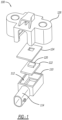
- FIG. 1 illustrates an exploded view of sensor assembly 100.
- the sensor assembly 100 includes a housing 110, a sensor 120, a gasket 124 and a cover 126.
- the sensor assembly 100 may be attached to a sheet metal panel 400 of the vehicle.
- the sensor 120 may be an accelerometer, gyroscope, pressure sensor, sound sensor, or other vehicle safety sensor.
- the housing 110 may include a cavity 112 to receive the sensor 120.
- the sensor 120 may be attached to a printed circuit board 122.
- the sensor 120 such as a PCB-less sensor package, may be mounted directly into the housing 110.
- the housing 110 may also include a connector portion 114 for connection to a vehicle wire harness assembly.
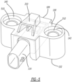
- FIG. 2 is an assembled perspective view of the sensor assembly 100.
- the connector portion 114 of the housing 110 extends through a slot 314 in the cover 126. Together the housing 110 and the cover 126 may form a housing assembly.
- the cover 126 includes a first mounting surface 130 and a second mounting surface 132.
- the first mounting surface 130 may be planar and may extend across substantially the entire cover 126.
- the second mounting surface 132 may also be planar and may extend across substantially the entire cover 126.
- the first mounting surface 130 may be on the opposite side of the cover 126 from the second mounting surface 132 and may face in an opposite direction from the second mounting surface 132.
- the first mounting surface 130 may extend substantially parallel to the second mounting surface 132.
- the first mounting surface 130 is configured for use as a wet side mounting surface.
- the second mounting surface 132 is configured for use as a dry side mounting surface.
- the cover 126 may be provided with two mounting holes 140 and 142.
- a mounting hole may be expected to have a certain relative position to a connector 114.
- mounting hole 140 may be used with one of the two mounting surfaces 130, 132 while mounting hole 142 may be used with the other of the two mounting surface 130, 132.
- both mounting holes 140, 142 may be used if maintaining the standard geometric configuration is not of particular concern.
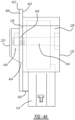
- FIG. 4A is an illustration showing the position of the sensor assembly in dry side mounting scenario, including the position of the sensor assembly 100 relative to the sheet metal panel 400 in a dry side mounting scenario.
- the first mounting surface 130 engages the dry side 410 of the sheet metal panel 400, and may be fastened to the sheet metal panel 400 using a fasteners 414 which may include screws, bolts or even clip lock mechanisms.
- the faster 414 may engage a nut 418 through an opening 416 in the sheet metal 410.
- the pressure port 210 extends through an opening 424 in the sheet metal panel 400.
- a gap 420 is provided in-between the dry (inner) side 410 of the sheet metal panel 400 and the connector 114. The gap 420 provides room for attachment of the connector 114 to a wire harness assembly.
- FIG. 5 illustrates one implementation where the first mounting hole 140 and the second mounting hole 142 are countersunk, allowing for the bolt head to be recessed into the cover 126 and a shorter bolt to be used for fastening the assembly to the sheet metal. Further, the bolt head may be flush to the mounting surface 130 of the cover 126 after installation.
- Both the first and second mounting holes 140 and 142 may be countersunk on one or both of the first mounting surface 130 and/or the second mounting surface 132.
- the first mounting hole 140 may be countersunk on one or both of the first mounting surface 130 and the second mounting surface 132.
- a shoulder 510 of the counter bore may be engaged by the fastener 414.
- the second mounting hole 142 may be countersunk on one or both of the first mounting surface 130 and the second mounting surface 132.
- a shoulder 512 may be engaged by the faster 414.
Landscapes
- Physics & Mathematics (AREA)
- General Physics & Mathematics (AREA)
- Chemical & Material Sciences (AREA)
- Analytical Chemistry (AREA)
- Engineering & Computer Science (AREA)
- Mechanical Engineering (AREA)
- Casings For Electric Apparatus (AREA)
- Measuring Fluid Pressure (AREA)
Description
- This application claims the benefit of
U.S. Serial No. 15/788,800, entitled "Dual Wet And Dry Combination Mounting," filed October 19, 2017 - The present application relates generally to a sensor assembly that is configured to be mounted on either a wet side or a dry side of a vehicle panel.
US6439058B proposes a semiconductor sensor.US20150143901A proposes a sensor for detecting a predetermined characteristic of an atmosphere.US20140137656A proposes a sensor device with a particular use in a motor vehicle.US20100140419A proposes an accident sensor. - In satisfying the aboved need, as well as overcoming the many drawbacks and other limitations of the related art, the present application provides a sensor assembly for combination wet side and dry side mounting. Specifically, the sensor housing may be designed for mounting on either the wet side of the sheet metal or the dry side of the sheet metal. As such, the mounting surface may be on either a first side of the housing assembly where only the pressure port extends through a hole in the sheet metal and the rest of the sensor assembly remains on the dry side of the sheet metal or the mounting surface is on a second side of the housing assembly where the entire housing assembly is mounted on the wet side of the sheet metal.
- The mountable sensor assembly includes a sensor circuit and a sensor housing assembly. The sensor housing assembly includes a first mounting surface, a second mounting surface, and a connector. The first mounting surface being on first side of the connector such that mounting the sensor housing using the first mounting surface would comprise a wet side mounting of the mountable sensor assembly and mounting the sensor housing using the second mounting surface would comprise a dry side mounting of the mountable sensor assembly.
- Further objects, features and advantages of this application will become readily apparent to persons skilled in the art after a review of the following description, with reference to the drawings and claims that are appended to and form a part of this specification.
- In the accompanying drawings the components are not necessarily to scale, emphasis instead being placed upon illustrating the principles of the application. Moreover, like reference numerals designate corresponding parts throughout the views.
-
FIG. 1 illustrates an exploded view of sensor assembly. -
FIG. 2 is an assembled perspective view of the sensor assembly. -
FIG. 3 is an perspective view of a cover of the sensor assembly. -
FIG. 4A is an illustration showing the position of the sensor assembly in a wet side mounting scenario. -
FIG. 4B is an illustration showing the position of the sensor assembly in dry side mounting scenario. -
FIG. 5 is a perspective view illustrating one implementation of the sensor assembly with countersunk mounting holes. - Currently there are two options for the location to mount a pressure sensor. They can be mounted on the dry side of a vehicle door panel and have a pressure port protruding into the wet side for pressure transmission, or the sensor assembly can be located entirely on the wet side of the door panel. This methodology necessitates two separate designs to accommodate both mounting types. However, the implementations discussed herein improve upon this sub-optimal design by allowing for a single housing to be mounted on either the wet side or the dry side of a door panel. This allows for a more singular design approach and increased volume on that single design. The implementations provided include a "snap fit" configuration for assembly but other methods of assembling the components may be readily used. Various different methods of assembly may include (laser weld, vibration weld, potting, etc.)
- One feature of the described implementations is a mounting configuration that allows for pressure sensing regardless of desired mounting location (wet side or dry side). This configuration may involve mounting surfaces extending out to the edge of the package to allow for mating with the vehicle sheet metal on both sides of the housing assembly. The dual wet side and dry side mounting allows for the number of pressure sensor designs to be reduced from two separate wet side and dry side designs to one single design.
- Another feature of the described implementations may be the use of countersunk holes to allow for a shorter mounting bolt to be used to attach this sensor assembly to the vehicle (from both sides). The countersunk holes allow for the use of shorter (less expensive) mounting bolts to be used to attach this sensor assembly to the vehicle.
- As such, the designs discussed could be sold to all OEMs that use pressure sensors with wet side mounting or dry side mounting configurations.
-
FIG. 1 illustrates an exploded view ofsensor assembly 100. Thesensor assembly 100 includes ahousing 110, asensor 120, agasket 124 and acover 126. Thesensor assembly 100 may be attached to asheet metal panel 400 of the vehicle. As such, thesensor 120 may be an accelerometer, gyroscope, pressure sensor, sound sensor, or other vehicle safety sensor. Thehousing 110 may include acavity 112 to receive thesensor 120. In some implementations, thesensor 120 may be attached to aprinted circuit board 122. In other implementations, thesensor 120, such as a PCB-less sensor package, may be mounted directly into thehousing 110. Thehousing 110 may also include aconnector portion 114 for connection to a vehicle wire harness assembly. As such, thesensor 110 may be electrically connected to pins located within theconnector portion 114. Thegasket 124 may be located between thesensor 120 and thecover 126. As the cover is seated on thehousing 110, thegasket 124 may provide sealing between thecover 126 and thehousing 110 preventing moisture or other elements to travel into thecavity 112. Thecover 126 and thehousing 110 may include one or more snap fit features to retain thehousing 110 within thecover 126. -
FIG. 2 is an assembled perspective view of thesensor assembly 100. Theconnector portion 114 of thehousing 110 extends through aslot 314 in thecover 126. Together thehousing 110 and thecover 126 may form a housing assembly. Thecover 126 includes afirst mounting surface 130 and asecond mounting surface 132. Thefirst mounting surface 130 may be planar and may extend across substantially theentire cover 126. Thesecond mounting surface 132 may also be planar and may extend across substantially theentire cover 126. Thefirst mounting surface 130 may be on the opposite side of thecover 126 from thesecond mounting surface 132 and may face in an opposite direction from thesecond mounting surface 132. Thefirst mounting surface 130 may extend substantially parallel to thesecond mounting surface 132. Thefirst mounting surface 130 is configured for use as a wet side mounting surface. Thesecond mounting surface 132 is configured for use as a dry side mounting surface. - A
pressure port 210 extends from thefirst mounting surface 130 such that when thefirst mounting surface 130 is mounted against adry side 412 of thesheet metal panel 400 of the door, thepressure port 210 extends through anopening 416 in thesheet metal panel 400 and allow communication to awet side 410 of thesheet metal panel 400. When thesecond mounting surface 132 is mounted against thewet side 410 of thesheet metal panel 400, both thepressure port 210 and theconnector portion 114 may be located on the same side, thewet side 410, of thesheet metal panel 400. For example, both theconnector 114 and thepressure port 210 may be located in the wet area or the external side of the sheet metal. - The
cover 126 may be provided with two mountingholes connector 114. To maintain the expected geometric configuration between the mounting hole and theconnector 114 position, mountinghole 140 may be used with one of the two mountingsurfaces hole 142 may be used with the other of the two mountingsurface holes -
FIG. 3 is an perspective view of thecover 126. Thecover 126 includes anopening 312 for receiving thehousing 110. Edges of thecover 126 around theopening 312 may be chamfered to center the housing in theopening 312. The cover may have aninner opening 310 that coordinates with the pressure port, providing access to thesensor 120 within thehousing 110. Further, theconnector 114 may extend through theslot 314 provided in thecover 126. In some implementations, aslot 316 may be provided to provide stress relief as thehousing 110 may be snap fit into theopening 312 by lockingfeatures 318 located around the outer edge of theopening 312. The locking features 318 may engage thehousing 110 and lock the position and orientation of thehousing 110 relative to thecover 126. -
FIG. 4A is an illustration showing the position of the sensor assembly in dry side mounting scenario, including the position of thesensor assembly 100 relative to thesheet metal panel 400 in a dry side mounting scenario. Thefirst mounting surface 130 engages thedry side 410 of thesheet metal panel 400, and may be fastened to thesheet metal panel 400 using afasteners 414 which may include screws, bolts or even clip lock mechanisms. The faster 414 may engage anut 418 through anopening 416 in thesheet metal 410. Thepressure port 210 extends through anopening 424 in thesheet metal panel 400. In addition, agap 420 is provided in-between the dry (inner)side 410 of thesheet metal panel 400 and theconnector 114. Thegap 420 provides room for attachment of theconnector 114 to a wire harness assembly. -
FIG. 4B illustrates the position of thesensor assembly 100 in a wet side mounting scenario, including the position of thesensor assembly 100 relative to thesheet metal panel 400 in a wet side mounting scenario. Thesecond mounting surface 132 engages the wet (outer)side 412 of thesheet metal panel 400. Again, the position of the second mountingsurface 132 relative tosheet metal panel 400 may be locked into place using afastener 414, thereby locking the position and orientation of thesensor assembly 100 relative to thesheet metal panel 400. The faster 414 may engage a nut on an opposite end of the mounting hole. The position of the second mountingsurface 132 provides agap 422 between the wet (outer)side 412 of thesheet metal panel 400 and theconnector surface 114. Thegap 422 provides room for attachment of the wire harness to theconnector 114. - The
gap 420 andgap 422 may be a function of the standoff between theconnector 114 and the first mountingsurface 130 and the standoff betweenconnector 114 and the second mountingsurface 132. In addition, the first mountingsurface 130 being parallel to the second mountingsurface 132 may provide the minimum clearance when mounting on either surface. In addition, theconnector 114 being locked into the opening of the housing in an orientation parallel with both the first mountingsurface 130 and the second mountingsurface 132 provides a symmetric geometry that may lend itself to both dry side mounting and wet side mounting scenarios. In some implementations, gap 420 (e.g. standoff) may be equal to thegap 422. In some implementations, thegap 420 and thegap 422 may be greater than 10 mm. - Certain mounting standards in the industry can specify the position of the
connector 114 relative to the mountingholes cover 126 may be provided with two mountingholes cover 126. Accordingly, in the dry side mounting scenario, one of the twoholes holes hole 140 may correspond to a location and orientation defined in a standard relative to a position of theconnector 114 with the first mountingsurface 130 against thedry side 410 of sheet metal panel 400 (e.g. the dry side mounting scenario). Also, the location and orientation of thesecond mounting hole 142 may correspond to a location and orientation defined in a standard relative to a position of theconnector 114 with the second mountingsurface 132 against thewet side 412 ofsheet metal panel 400. -
FIG. 5 illustrates one implementation where the first mountinghole 140 and thesecond mounting hole 142 are countersunk, allowing for the bolt head to be recessed into thecover 126 and a shorter bolt to be used for fastening the assembly to the sheet metal. Further, the bolt head may be flush to the mountingsurface 130 of thecover 126 after installation. Both the first and second mountingholes surface 130 and/or the second mountingsurface 132. For example, the first mountinghole 140 may be countersunk on one or both of the first mountingsurface 130 and the second mountingsurface 132. As such, ashoulder 510 of the counter bore may be engaged by thefastener 414. Similarly, thesecond mounting hole 142 may be countersunk on one or both of the first mountingsurface 130 and the second mountingsurface 132. As such, ashoulder 512 may be engaged by the faster 414. - As a person skilled in the art will readily appreciate, the above description is meant as an illustration of the principles of this application. This description is not intended to limit the scope or application of the claim in that the assembly is susceptible to modification, variation and change, without departing from the invention, as defined in the following claims.
Claims (9)
- A mountable sensor assembly (100) for mounting on a sheet metal panel (400) of a vehicle assembly, the sheet metal panel having a wet side (410) and a dry side (412), the mountable sensor assembly comprising:a sensor circuit (120); anda sensor housing assembly housing the sensor circuit and comprising a first mounting surface (130), a second mounting surface (132), and a connector (114), such that mounting the first mounting surface of the sensor housing assembly to a dry side of the sheet metal panel comprises a dry side mounting configuration of the mountable sensor assembly, and mounting the second surface of the sensor housing assembly to a wet side of the sheet metal panel comprises a wet side mounting configuration of the mountable sensor assembly,wherein a pressure port (210) is on the first mounting surface and configured to extend through an opening in the sheet metal panel when the mountable sensor assembly is in the dry side mounting configuration,and wherein the first mounting surface is offset from the connector to provide a first standoff (420), the first standoff (420) providing a gap between the dry inner side (410) of the sheet metal panel (400) and the connector (114) in the dry side mounting configuration and the second mounting surface is offset from the connector to provide a second standoff (422), the second standoff (422) providing a gap between the wet outer side (412) of the sheet metal panel (400) and the connector (114) in the wet side mounting configuration.
- The mountable sensor assembly (100) according to claim 1, wherein the sensor housing assembly comprises:a sensor housing (110) comprising a cavity (112) configured to receive the sensor circuit (120) and comprising the connector (114);a cover (126) configured to extend over the sensor housing (110), the cover comprising the first mounting surface (130) and the second mounting surface (132), anda gasket (124) positioned between the cover (126) and the sensor housing (110) to seal the cavity.
- The sensor assembly (100) according to claim 2, wherein the cover (126) is snap fit onto the sensor housing (110).
- The sensor assembly (100) according to any preceding claim, wherein the first mounting surface (130) extends parallel to the second mounting surface (132).
- The sensor assembly (100) according to any preceding claim, wherein the connector (114) is parallel to the first mounting surface (130) and the second mounting surface (132).
- The sensor assembly (100) according to either of claims 2 or 3, or either of claims 4 or 5 when dependent on claim 2, wherein the cover (126) has a first mounting hole (140) on a first side of the connector (114) and a second mounting hole (142) on a second side of the connector.
- The sensor assembly (100) according to claim 6, wherein the first mounting hole and the second mounting hole are countersunk.
- The sensor assembly (100) according to any preceding claim, wherein the first standoff (420) and the second standoff (422) are greater than 10 mm.
- The sensor assembly (100) according to any preceding claim, wherein the first standoff (420) and the second standoff (422) are equal.
Applications Claiming Priority (2)
| Application Number | Priority Date | Filing Date | Title |
|---|---|---|---|
| US15/788,800 US10605686B2 (en) | 2017-10-19 | 2017-10-19 | Dual wet and dry combination mounting |
| PCT/US2018/056274 WO2019079440A1 (en) | 2017-10-19 | 2018-10-17 | Dual wet and dry combination mounting |
Publications (3)
| Publication Number | Publication Date |
|---|---|
| EP3698106A1 EP3698106A1 (en) | 2020-08-26 |
| EP3698106A4 EP3698106A4 (en) | 2021-10-20 |
| EP3698106B1 true EP3698106B1 (en) | 2025-07-09 |
Family
ID=66171142
Family Applications (1)
| Application Number | Title | Priority Date | Filing Date |
|---|---|---|---|
| EP18869044.0A Active EP3698106B1 (en) | 2017-10-19 | 2018-10-17 | Dual wet and dry combination mounting |
Country Status (4)
| Country | Link |
|---|---|
| US (1) | US10605686B2 (en) |
| EP (1) | EP3698106B1 (en) |
| CN (1) | CN111226097B (en) |
| WO (1) | WO2019079440A1 (en) |
Families Citing this family (3)
| Publication number | Priority date | Publication date | Assignee | Title |
|---|---|---|---|---|
| GB2591461B (en) * | 2020-01-27 | 2022-08-03 | Datatecnics Corp Ltd | Apparatus and method for the detection of properties of a pipe |
| CN216594992U (en) * | 2020-10-14 | 2022-05-24 | 现代凯菲克株式会社 | Gas sensor |
| EP4255136A1 (en) * | 2022-03-30 | 2023-10-04 | Schneider Electric Buildings Americas, Inc. | Bezel for a multi-sensor device |
Family Cites Families (15)
| Publication number | Priority date | Publication date | Assignee | Title |
|---|---|---|---|---|
| US6244287B1 (en) * | 1999-08-03 | 2001-06-12 | Syltone Industries, Llc | System and method for dynamically purging cargo tank wet lines |
| JP4281178B2 (en) * | 1999-10-06 | 2009-06-17 | 株式会社デンソー | Semiconductor pressure sensor |
| US7291023B1 (en) | 2006-11-21 | 2007-11-06 | Autoliv Asp, Inc. | Electric vehicle motion sensor |
| DE102007008862A1 (en) * | 2007-02-23 | 2008-08-28 | Robert Bosch Gmbh | crash sensor |
| US7380458B1 (en) | 2007-03-02 | 2008-06-03 | Autoliv Asp, Inc. | Pressure sensor port |
| US7578194B1 (en) * | 2008-02-11 | 2009-08-25 | Sensata Technologies, Inc. | Differential fluid pressure measurement apparatus |
| DE102008040155A1 (en) * | 2008-07-03 | 2010-01-07 | Robert Bosch Gmbh | Sensor housing cover and method of making such a sensor housing cover |
| DE102009045722B4 (en) * | 2009-10-15 | 2021-09-16 | Robert Bosch Gmbh | Component carrier |
| DE102010020961A1 (en) * | 2010-04-30 | 2011-11-03 | Continental Automotive Gmbh | Method and fastening device for fastening an assembly in an opening of a wall of a vehicle |
| DE102011079446A1 (en) * | 2011-07-20 | 2013-02-07 | Robert Bosch Gmbh | Sensor device, in particular for use in a motor vehicle |
| US20130025043A1 (en) * | 2011-07-25 | 2013-01-31 | Hui Wing-Kin | Device for facilitating interchangeability of pool applicances for above ground pools |
| JP2014126495A (en) * | 2012-12-27 | 2014-07-07 | Seiko Epson Corp | Sensor, electronic apparatus, and moving body |
| JP6533380B2 (en) | 2013-11-11 | 2019-06-19 | 日本特殊陶業株式会社 | Sensor |
| US9260071B2 (en) | 2014-03-11 | 2016-02-16 | Trw Automotive U.S. Llc | Apparatus for snap mounting a crash sensor |
| US9470595B2 (en) * | 2014-08-29 | 2016-10-18 | Trw Automotive U.S. Llc | Apparatus for dry side mounting a crash pressure sensor |
-
2017
- 2017-10-19 US US15/788,800 patent/US10605686B2/en active Active
-
2018
- 2018-10-17 CN CN201880066908.9A patent/CN111226097B/en active Active
- 2018-10-17 EP EP18869044.0A patent/EP3698106B1/en active Active
- 2018-10-17 WO PCT/US2018/056274 patent/WO2019079440A1/en not_active Ceased
Also Published As
| Publication number | Publication date |
|---|---|
| WO2019079440A1 (en) | 2019-04-25 |
| CN111226097B (en) | 2023-04-21 |
| EP3698106A1 (en) | 2020-08-26 |
| CN111226097A (en) | 2020-06-02 |
| US20190120714A1 (en) | 2019-04-25 |
| US10605686B2 (en) | 2020-03-31 |
| EP3698106A4 (en) | 2021-10-20 |
Similar Documents
| Publication | Publication Date | Title |
|---|---|---|
| EP3698106B1 (en) | Dual wet and dry combination mounting | |
| US7358438B2 (en) | Sandwich housing for an antenna amplifier | |
| US7819004B2 (en) | Vehicle sensor | |
| US11026340B2 (en) | Passenger protection control device | |
| US8210037B2 (en) | Sensor module with a housing which may be mounted on a wall | |
| US10159157B2 (en) | Compliant PCB-to-housing fastener | |
| US6135726A (en) | Power steering power pack motor/pump mounting bracket | |
| US10883863B2 (en) | Interchangeable sensor mounting | |
| WO2024097058A1 (en) | Hook and snap pressure sensor assembly | |
| KR20070121539A (en) | Forced fitting of sensor assembly in electronic throttle valve control | |
| US9623727B2 (en) | Accessory mounting system for laminated glass windshield | |
| US12540838B2 (en) | Bracket assembly | |
| KR102277840B1 (en) | Pressure sensor | |
| JP2014108648A (en) | Vehicular electronic control unit | |
| CN104251077B (en) | Component with belt fastener and intelligent key | |
| US11209295B2 (en) | Double hook snap fit for electronic housing | |
| CN106165210A (en) | Protective plate for plug-in connector system | |
| JP4793221B2 (en) | Electronic component mounting structure and electronic component mounting method | |
| TW202019151A (en) | Camera device comprising a lens module, a mounting shell, and a back abutting member for easily changing exterior design | |
| US10343637B2 (en) | Mistake proof brackets for installation of seat trim cover airbag strip to a seat frame | |
| US11231302B2 (en) | Bi-directional snap fit electronic unit | |
| JP6169513B2 (en) | Electronic control unit | |
| JPH08162779A (en) | Electronic control unit | |
| JP2003087944A (en) | Grommet | |
| CN107366490B (en) | Automatic door, method for assembling automatic door, and component unit of automatic door |
Legal Events
| Date | Code | Title | Description |
|---|---|---|---|
| STAA | Information on the status of an ep patent application or granted ep patent |
Free format text: STATUS: THE INTERNATIONAL PUBLICATION HAS BEEN MADE |
|
| PUAI | Public reference made under article 153(3) epc to a published international application that has entered the european phase |
Free format text: ORIGINAL CODE: 0009012 |
|
| STAA | Information on the status of an ep patent application or granted ep patent |
Free format text: STATUS: REQUEST FOR EXAMINATION WAS MADE |
|
| 17P | Request for examination filed |
Effective date: 20200320 |
|
| AK | Designated contracting states |
Kind code of ref document: A1 Designated state(s): AL AT BE BG CH CY CZ DE DK EE ES FI FR GB GR HR HU IE IS IT LI LT LU LV MC MK MT NL NO PL PT RO RS SE SI SK SM TR |
|
| AX | Request for extension of the european patent |
Extension state: BA ME |
|
| DAV | Request for validation of the european patent (deleted) | ||
| DAX | Request for extension of the european patent (deleted) | ||
| A4 | Supplementary search report drawn up and despatched |
Effective date: 20210921 |
|
| RIC1 | Information provided on ipc code assigned before grant |
Ipc: G01P 1/02 20060101ALI20210915BHEP Ipc: G01P 1/00 20060101ALI20210915BHEP Ipc: G01L 19/14 20060101ALI20210915BHEP Ipc: G01D 11/24 20060101AFI20210915BHEP |
|
| RAP3 | Party data changed (applicant data changed or rights of an application transferred) |
Owner name: VEONEER US, LLC |
|
| RAP3 | Party data changed (applicant data changed or rights of an application transferred) |
Owner name: VEONEER US, LLC |
|
| RAP1 | Party data changed (applicant data changed or rights of an application transferred) |
Owner name: VEONEER US SAFETY SYSTEMS, LLC |
|
| STAA | Information on the status of an ep patent application or granted ep patent |
Free format text: STATUS: EXAMINATION IS IN PROGRESS |
|
| 17Q | First examination report despatched |
Effective date: 20240411 |
|
| GRAP | Despatch of communication of intention to grant a patent |
Free format text: ORIGINAL CODE: EPIDOSNIGR1 |
|
| STAA | Information on the status of an ep patent application or granted ep patent |
Free format text: STATUS: GRANT OF PATENT IS INTENDED |
|
| INTG | Intention to grant announced |
Effective date: 20250205 |
|
| GRAS | Grant fee paid |
Free format text: ORIGINAL CODE: EPIDOSNIGR3 |
|
| GRAA | (expected) grant |
Free format text: ORIGINAL CODE: 0009210 |
|
| STAA | Information on the status of an ep patent application or granted ep patent |
Free format text: STATUS: THE PATENT HAS BEEN GRANTED |
|
| AK | Designated contracting states |
Kind code of ref document: B1 Designated state(s): AL AT BE BG CH CY CZ DE DK EE ES FI FR GB GR HR HU IE IS IT LI LT LU LV MC MK MT NL NO PL PT RO RS SE SI SK SM TR |
|
| REG | Reference to a national code |
Ref country code: GB Ref legal event code: FG4D |
|
| REG | Reference to a national code |
Ref country code: CH Ref legal event code: EP |
|
| REG | Reference to a national code |
Ref country code: IE Ref legal event code: FG4D |
|
| REG | Reference to a national code |
Ref country code: DE Ref legal event code: R096 Ref document number: 602018083491 Country of ref document: DE |
|
| REG | Reference to a national code |
Ref country code: NL Ref legal event code: MP Effective date: 20250709 |
|
| PG25 | Lapsed in a contracting state [announced via postgrant information from national office to epo] |
Ref country code: PT Free format text: LAPSE BECAUSE OF FAILURE TO SUBMIT A TRANSLATION OF THE DESCRIPTION OR TO PAY THE FEE WITHIN THE PRESCRIBED TIME-LIMIT Effective date: 20251110 |
|
| PG25 | Lapsed in a contracting state [announced via postgrant information from national office to epo] |
Ref country code: NL Free format text: LAPSE BECAUSE OF FAILURE TO SUBMIT A TRANSLATION OF THE DESCRIPTION OR TO PAY THE FEE WITHIN THE PRESCRIBED TIME-LIMIT Effective date: 20250709 |
|
| REG | Reference to a national code |
Ref country code: AT Ref legal event code: MK05 Ref document number: 1812169 Country of ref document: AT Kind code of ref document: T Effective date: 20250709 |
|
| PG25 | Lapsed in a contracting state [announced via postgrant information from national office to epo] |
Ref country code: IS Free format text: LAPSE BECAUSE OF FAILURE TO SUBMIT A TRANSLATION OF THE DESCRIPTION OR TO PAY THE FEE WITHIN THE PRESCRIBED TIME-LIMIT Effective date: 20251109 |
|
| PGFP | Annual fee paid to national office [announced via postgrant information from national office to epo] |
Ref country code: DE Payment date: 20251031 Year of fee payment: 8 |
|
| PG25 | Lapsed in a contracting state [announced via postgrant information from national office to epo] |
Ref country code: NO Free format text: LAPSE BECAUSE OF FAILURE TO SUBMIT A TRANSLATION OF THE DESCRIPTION OR TO PAY THE FEE WITHIN THE PRESCRIBED TIME-LIMIT Effective date: 20251009 |
|
| REG | Reference to a national code |
Ref country code: LT Ref legal event code: MG9D |
|
| PG25 | Lapsed in a contracting state [announced via postgrant information from national office to epo] |
Ref country code: AT Free format text: LAPSE BECAUSE OF FAILURE TO SUBMIT A TRANSLATION OF THE DESCRIPTION OR TO PAY THE FEE WITHIN THE PRESCRIBED TIME-LIMIT Effective date: 20250709 |
|
| PG25 | Lapsed in a contracting state [announced via postgrant information from national office to epo] |
Ref country code: FI Free format text: LAPSE BECAUSE OF FAILURE TO SUBMIT A TRANSLATION OF THE DESCRIPTION OR TO PAY THE FEE WITHIN THE PRESCRIBED TIME-LIMIT Effective date: 20250709 |
|
| PG25 | Lapsed in a contracting state [announced via postgrant information from national office to epo] |
Ref country code: HR Free format text: LAPSE BECAUSE OF FAILURE TO SUBMIT A TRANSLATION OF THE DESCRIPTION OR TO PAY THE FEE WITHIN THE PRESCRIBED TIME-LIMIT Effective date: 20250709 |
|
| PGFP | Annual fee paid to national office [announced via postgrant information from national office to epo] |
Ref country code: FR Payment date: 20251031 Year of fee payment: 8 |
|
| PG25 | Lapsed in a contracting state [announced via postgrant information from national office to epo] |
Ref country code: GR Free format text: LAPSE BECAUSE OF FAILURE TO SUBMIT A TRANSLATION OF THE DESCRIPTION OR TO PAY THE FEE WITHIN THE PRESCRIBED TIME-LIMIT Effective date: 20251010 |
|
| PG25 | Lapsed in a contracting state [announced via postgrant information from national office to epo] |
Ref country code: SE Free format text: LAPSE BECAUSE OF FAILURE TO SUBMIT A TRANSLATION OF THE DESCRIPTION OR TO PAY THE FEE WITHIN THE PRESCRIBED TIME-LIMIT Effective date: 20250709 |
|
| PG25 | Lapsed in a contracting state [announced via postgrant information from national office to epo] |
Ref country code: LV Free format text: LAPSE BECAUSE OF FAILURE TO SUBMIT A TRANSLATION OF THE DESCRIPTION OR TO PAY THE FEE WITHIN THE PRESCRIBED TIME-LIMIT Effective date: 20250709 |
|
| PG25 | Lapsed in a contracting state [announced via postgrant information from national office to epo] |
Ref country code: BG Free format text: LAPSE BECAUSE OF FAILURE TO SUBMIT A TRANSLATION OF THE DESCRIPTION OR TO PAY THE FEE WITHIN THE PRESCRIBED TIME-LIMIT Effective date: 20250709 Ref country code: PL Free format text: LAPSE BECAUSE OF FAILURE TO SUBMIT A TRANSLATION OF THE DESCRIPTION OR TO PAY THE FEE WITHIN THE PRESCRIBED TIME-LIMIT Effective date: 20250709 |
|
| PG25 | Lapsed in a contracting state [announced via postgrant information from national office to epo] |
Ref country code: RS Free format text: LAPSE BECAUSE OF FAILURE TO SUBMIT A TRANSLATION OF THE DESCRIPTION OR TO PAY THE FEE WITHIN THE PRESCRIBED TIME-LIMIT Effective date: 20251009 |
|
| PG25 | Lapsed in a contracting state [announced via postgrant information from national office to epo] |
Ref country code: ES Free format text: LAPSE BECAUSE OF FAILURE TO SUBMIT A TRANSLATION OF THE DESCRIPTION OR TO PAY THE FEE WITHIN THE PRESCRIBED TIME-LIMIT Effective date: 20250709 |
|
| P01 | Opt-out of the competence of the unified patent court (upc) registered |
Free format text: CASE NUMBER: UPC_APP_0002691_3698106/2026 Effective date: 20260126 |
|
| PG25 | Lapsed in a contracting state [announced via postgrant information from national office to epo] |
Ref country code: RO Free format text: LAPSE BECAUSE OF FAILURE TO SUBMIT A TRANSLATION OF THE DESCRIPTION OR TO PAY THE FEE WITHIN THE PRESCRIBED TIME-LIMIT Effective date: 20250709 |
|
| PG25 | Lapsed in a contracting state [announced via postgrant information from national office to epo] |
Ref country code: SM Free format text: LAPSE BECAUSE OF FAILURE TO SUBMIT A TRANSLATION OF THE DESCRIPTION OR TO PAY THE FEE WITHIN THE PRESCRIBED TIME-LIMIT Effective date: 20250709 |
|
| PG25 | Lapsed in a contracting state [announced via postgrant information from national office to epo] |
Ref country code: DK Free format text: LAPSE BECAUSE OF FAILURE TO SUBMIT A TRANSLATION OF THE DESCRIPTION OR TO PAY THE FEE WITHIN THE PRESCRIBED TIME-LIMIT Effective date: 20250709 |
|
| PG25 | Lapsed in a contracting state [announced via postgrant information from national office to epo] |
Ref country code: IT Free format text: LAPSE BECAUSE OF FAILURE TO SUBMIT A TRANSLATION OF THE DESCRIPTION OR TO PAY THE FEE WITHIN THE PRESCRIBED TIME-LIMIT Effective date: 20250709 |
|
| PG25 | Lapsed in a contracting state [announced via postgrant information from national office to epo] |
Ref country code: CZ Free format text: LAPSE BECAUSE OF FAILURE TO SUBMIT A TRANSLATION OF THE DESCRIPTION OR TO PAY THE FEE WITHIN THE PRESCRIBED TIME-LIMIT Effective date: 20250709 |
|
| PG25 | Lapsed in a contracting state [announced via postgrant information from national office to epo] |
Ref country code: EE Free format text: LAPSE BECAUSE OF FAILURE TO SUBMIT A TRANSLATION OF THE DESCRIPTION OR TO PAY THE FEE WITHIN THE PRESCRIBED TIME-LIMIT Effective date: 20250709 Ref country code: SK Free format text: LAPSE BECAUSE OF FAILURE TO SUBMIT A TRANSLATION OF THE DESCRIPTION OR TO PAY THE FEE WITHIN THE PRESCRIBED TIME-LIMIT Effective date: 20250709 |