EP3698087B1 - Flow control arrangement for an air ventilation system - Google Patents
Flow control arrangement for an air ventilation system Download PDFInfo
- Publication number
- EP3698087B1 EP3698087B1 EP18869148.9A EP18869148A EP3698087B1 EP 3698087 B1 EP3698087 B1 EP 3698087B1 EP 18869148 A EP18869148 A EP 18869148A EP 3698087 B1 EP3698087 B1 EP 3698087B1
- Authority
- EP
- European Patent Office
- Prior art keywords
- damper
- ahu
- air
- short cut
- ecu
- Prior art date
- Legal status (The legal status is an assumption and is not a legal conclusion. Google has not performed a legal analysis and makes no representation as to the accuracy of the status listed.)
- Active
Links
Images

Classifications
-
- F—MECHANICAL ENGINEERING; LIGHTING; HEATING; WEAPONS; BLASTING
- F24—HEATING; RANGES; VENTILATING
- F24F—AIR-CONDITIONING; AIR-HUMIDIFICATION; VENTILATION; USE OF AIR CURRENTS FOR SCREENING
- F24F13/00—Details common to, or for air-conditioning, air-humidification, ventilation or use of air currents for screening
- F24F13/08—Air-flow control members, e.g. louvres, grilles, flaps or guide plates
- F24F13/10—Air-flow control members, e.g. louvres, grilles, flaps or guide plates movable, e.g. dampers
-
- F—MECHANICAL ENGINEERING; LIGHTING; HEATING; WEAPONS; BLASTING
- F24—HEATING; RANGES; VENTILATING
- F24F—AIR-CONDITIONING; AIR-HUMIDIFICATION; VENTILATION; USE OF AIR CURRENTS FOR SCREENING
- F24F11/00—Control or safety arrangements
- F24F11/30—Control or safety arrangements for purposes related to the operation of the system, e.g. for safety or monitoring
- F24F11/41—Defrosting; Preventing freezing
-
- F—MECHANICAL ENGINEERING; LIGHTING; HEATING; WEAPONS; BLASTING
- F24—HEATING; RANGES; VENTILATING
- F24F—AIR-CONDITIONING; AIR-HUMIDIFICATION; VENTILATION; USE OF AIR CURRENTS FOR SCREENING
- F24F11/00—Control or safety arrangements
- F24F11/70—Control systems characterised by their outputs; Constructional details thereof
- F24F11/80—Control systems characterised by their outputs; Constructional details thereof for controlling the temperature of the supplied air
- F24F11/81—Control systems characterised by their outputs; Constructional details thereof for controlling the temperature of the supplied air by controlling the air supply to heat-exchangers or bypass channels
-
- F—MECHANICAL ENGINEERING; LIGHTING; HEATING; WEAPONS; BLASTING
- F24—HEATING; RANGES; VENTILATING
- F24F—AIR-CONDITIONING; AIR-HUMIDIFICATION; VENTILATION; USE OF AIR CURRENTS FOR SCREENING
- F24F12/00—Use of energy recovery systems in air conditioning, ventilation or screening
- F24F12/001—Use of energy recovery systems in air conditioning, ventilation or screening with heat-exchange between supplied and exhausted air
- F24F12/006—Use of energy recovery systems in air conditioning, ventilation or screening with heat-exchange between supplied and exhausted air using an air-to-air heat exchanger
-
- F—MECHANICAL ENGINEERING; LIGHTING; HEATING; WEAPONS; BLASTING
- F24—HEATING; RANGES; VENTILATING
- F24F—AIR-CONDITIONING; AIR-HUMIDIFICATION; VENTILATION; USE OF AIR CURRENTS FOR SCREENING
- F24F13/00—Details common to, or for air-conditioning, air-humidification, ventilation or use of air currents for screening
- F24F13/08—Air-flow control members, e.g. louvres, grilles, flaps or guide plates
- F24F13/10—Air-flow control members, e.g. louvres, grilles, flaps or guide plates movable, e.g. dampers
- F24F13/12—Air-flow control members, e.g. louvres, grilles, flaps or guide plates movable, e.g. dampers built up of sliding members
-
- F—MECHANICAL ENGINEERING; LIGHTING; HEATING; WEAPONS; BLASTING
- F24—HEATING; RANGES; VENTILATING
- F24F—AIR-CONDITIONING; AIR-HUMIDIFICATION; VENTILATION; USE OF AIR CURRENTS FOR SCREENING
- F24F12/00—Use of energy recovery systems in air conditioning, ventilation or screening
- F24F12/001—Use of energy recovery systems in air conditioning, ventilation or screening with heat-exchange between supplied and exhausted air
- F24F2012/007—Use of energy recovery systems in air conditioning, ventilation or screening with heat-exchange between supplied and exhausted air using a by-pass for bypassing the heat-exchanger
-
- F—MECHANICAL ENGINEERING; LIGHTING; HEATING; WEAPONS; BLASTING
- F24—HEATING; RANGES; VENTILATING
- F24F—AIR-CONDITIONING; AIR-HUMIDIFICATION; VENTILATION; USE OF AIR CURRENTS FOR SCREENING
- F24F2110/00—Control inputs relating to air properties
- F24F2110/10—Temperature
-
- F—MECHANICAL ENGINEERING; LIGHTING; HEATING; WEAPONS; BLASTING
- F24—HEATING; RANGES; VENTILATING
- F24F—AIR-CONDITIONING; AIR-HUMIDIFICATION; VENTILATION; USE OF AIR CURRENTS FOR SCREENING
- F24F2110/00—Control inputs relating to air properties
- F24F2110/20—Humidity
-
- Y—GENERAL TAGGING OF NEW TECHNOLOGICAL DEVELOPMENTS; GENERAL TAGGING OF CROSS-SECTIONAL TECHNOLOGIES SPANNING OVER SEVERAL SECTIONS OF THE IPC; TECHNICAL SUBJECTS COVERED BY FORMER USPC CROSS-REFERENCE ART COLLECTIONS [XRACs] AND DIGESTS
- Y02—TECHNOLOGIES OR APPLICATIONS FOR MITIGATION OR ADAPTATION AGAINST CLIMATE CHANGE
- Y02B—CLIMATE CHANGE MITIGATION TECHNOLOGIES RELATED TO BUILDINGS, e.g. HOUSING, HOUSE APPLIANCES OR RELATED END-USER APPLICATIONS
- Y02B30/00—Energy efficient heating, ventilation or air conditioning [HVAC]
- Y02B30/56—Heat recovery units
Definitions
- the present invention relates to an Air Handling Unit providing fresh air to a building.
- the invention is in particular directed to the feature of making the air flow control more reliable in such a unit or system.
- AHU Air handling Unit
- HVAC Heating, Ventilation and Air Conditioning
- Such a heat exchanger can, for example, be a cross-flow or counter-flow heat exchanger (also called plate heat exchangers), and can be used for reducing the total energy consumption of the system by recovering a portion of the heat energy from the exhaust air before it is discharged.
- a heat exchanger in connection with the extract air duct transfers heat energy from the exhaust air flowing out to the outdoor air flowing in.
- frost or ice may form on the heat exchanger, which then has to go through a defrost cycle, during which the heat exchanger is heated to melt the ice.
- One way of performing defrosting (or deicing) of the extract air duct heat exchanger is to use the hot airflow leaving the building for heating and defrosting. In this case is the cold flow usually restricted or completely shut off in the part of the heat exchanger which shall be defrosted.
- Such a system is for example described in EP 2 546 581 or WO 01/22021 .
- WO 2011/022331 teaches a transport refrigeration unit which comprises a damper assembly which is configured to operatively block an airflow in a defrost mode.
- the invention is directed to solve a problem concerning the control of dampers which has been identified when developing Air Handling Units (AHUs) adapted for cold climates.
- AHUs Air Handling Units
- the problem is that a damper may get stuck in a position due to ice formation.
- the reasons for why a damper may get stuck from ice formation may be due to several factors. For example, in cold climates there is a particular need for making the heat recovery function as efficient as possible in order to avoid significant heat losses due to ventilation of warm exhaust air and intake of cold supply air into a building.
- the development of such devices also has the effect that some portions in the heat recovery arrangement may have low temperatures, below zero, and thus cause the water in the air to condense and freeze.
- the cold outside air is in general not a problem concerning condensing and ice formation since it in many cases is rather dry, at least when the temperature is well below zero, and is subjected to a heating operation enabling a higher water content to be present in the air.
- the risk for ice formation increases with the efficiency of the heat recovery arrangement since the more efficient the heat recovery arrangement is, the more will the warm side (the side from which heat is exhausted) in the heat arrangement be cooled down.
- this air stream which will be cooled down is the exhaust air which in general is warm and humid.
- a heat recovery arrangement will also be more vulnerable concerning ice formation when the temperatures decreases of the airflows since the system will work at lower temperatures generally.
- the desire for an increased efficiency in the system at low temperature as well as the low temperature itself contributes to an increased risk for ice formation in a heat recovery system.
- the change of the flow paths which may alter the humid exhaust air to change it through flow in the AHU or the HVAC system, together with the defrosting operation which will melt the ice formed in the system and add humidity to the air in the system, may cause the parts of the system to be subjected to a rather warm humid air.
- the system is reset and returned to normal operation after a defrost operation may there thus be air having a rather high water content which may condense on the surfaces in the surroundings.
- the closing of a damper in such an environment having condensed water from the air on the contact surfaces between the damper and the edges of the air channel through which air is flowing, may cause the damper to be stuck if the water starts to freeze.
- this risk is in particular high due to the defrost operation being performed which changes the temperature in different portion of the system while also, in general, changing the air flow through the systems and subjecting the system to air flows with a different water content compared to during normal, heat recovery operation and also inducing an increased humidity in the air due to melting of the ice.
- the system after a defrost operation will generally comprise air with higher water content while also closing certain dampers which in general are intended to be set in a set position until next defrost operation is needed.
- the invention is directed to preventing a damper in an Air Handling Unit or a Heating, Ventilation and Air Conditioning (HVAC) system in a building to be stuck in a closed position.
- HVAC Heating, Ventilation and Air Conditioning
- the invention relates to an air handling unit (AHU) in accordance with the features of appended claim 1 and a method for controlling a short cut damper in an air handling unit in accordance with the features of appended claim 11.
- AHU air handling unit
- Preferred embodiments are defined in the dependent claims.
- the damper arrangement comprises a damper and an Electronic Control Unit (ECU).
- the ECU may be a local ECU located on or in the vicinity of the damper or being more distant, e.g. forming part of a centralized control system.
- the ECU could be dedicated to only control the damper, control a group of dampers or control further elements or even the AHU or the HVAC system.
- the ECU is programmed to control the damper when the damper is changed from being in a first, open position (I) to a second, closed position (II) to be in a transition mode (III) before it will be in the second, closed position (II).
- the ECU is programmed to control the damper to oscillate or vibrate when the damper is in its transition mode (III).
- the transition mode (III) could for example set the damper to oscillate between being closed and open. Alternatively, the oscillations in the transition mode (III) could also be made by causing the damper to vibrate while the damper is in its closed position. It is an essential feature of the invention that said ECU is programmed to set the damper in said transition mode (III) after there has been a defrost cycle performed in the AHU.
- the vibrations or oscillations are intended to avoid the damper to be stuck due to freezing.
- the oscillations and vibrations may differ depending on the design of the damper.
- the dampers move rather slowly and there may be a cycle of almost a minute to perform an opening and closing action of the damper.
- the damper needs not to be fully opened when being oscillated between open and closed positions but the damper should be opened up such that there is no risk for contact surfaces between the damper plate and the edges of the air channel to be stuck to each other due to a freezing action.
- the ECU may be programmed to set the damper in the transition state for any desired time period, e.g. between 1 and 10 minutes.
- the damper arrangement could be used for a damper comprised in an Air Handling Unit (AHU).
- AHU comprises an extract air channel comprising at least one extract air inlet for guiding exhaust air from a building to the outside through at least one extract air outlet and a supply air channel comprising at least one supply air inlet for guiding fresh air from the outdoor into a building through at least one supply air outlet.
- the extract air channel and supply air channel are in a heat exchanging relation to each other via a heat exchanger.
- the damper arrangement is working as a short cut damper which controls a flow in a shortcut connection between the extract air channel and the supply air channel.
- the ECU could be programmed set the short cut damper in a first, essentially open position (I) and the extract air damper and supply air damper to be in a second, closed position (II) when the AHU (1) is working in a defrost mode.
- the extract air damper and supply air damper are changed to be in a first, essentially open position (I) and the short cut damper to be set in a transition mode (III) before being set in a second, closed position (II).
- the risk for ice formation and that a damper get stuck in the system due to freezing is in particular high when there is a drastic change of temperatures in different parts of the air ventilation system and when a damper is set to a closed position.
- the ECU could be connected to one or several temperatures sensors or temperature estimating means for estimating the temperature in the vicinity of the damper arrangement.
- the ECU could in this case be programmed to only control the damper arrangement to be in the transition mode (III) when there is an estimated risk for a temperature to be below zero degrees in the vicinity of the damper.
- the actual temperature of the air may be above zero while there still is a risk for ice formation on surfaces which may be below zero.
- the ECU could be connected to a humidity sensor or a humidity estimating means and is programmed to set the damper in said transition mode (III) in dependence of the humidity. It may of course be possible to use both the humidity values and temperatures in order to evaluate if the damper should be set in the transition mode (III).
- the ECU could be programmed to set the damper in the transition mode (III) after there has been a defrost cycle performed in the AHU or in some part of the HVAC system.
- the damper be arranged such that the material of the damper and/or the edges of the air duct which forms the contact surfaces are made from a hydrophobic material and having a surface with hydrophobic properties, e.g. silicone.
- the time period for how long the damper arrangement should be in the transition mode (III) may be hard to decide. In many cases, the time period will be set to a threshold value which by testing and operation of the damper arrangement may be adjusted and improved. The time period could for example be dependent on temperatures and humidity. Still another method for deciding when to end the transition mode (III) could be to program the ECU to lift the damper from its closed position to its open position with a predefined time interval and increasing the time interval as long as the force needed to lift the damper to an open position is essentially the same. Hence, when there is an ice formation on the contact surfaces will there be a stronger force needed to separate the damper from the contact surface.
- the ECU could be programmed to in its transition mode to lift the damper from its closed position to its open position with a predefined time interval, said time decreasing when the force needed to lift the damper to an open position is increasing in order to prevent the damper from being stuck due to ice formation.
- An increased force needed to open or oscillate the damper indicates that ice have been formed on the contact surfaces.
- a damper is particularly vulnerable to be stuck by ice formation after a defrost operation has been performed due to release of water in the system and an increased temperature.
- the damper arrangement is thus in particular suitable for a damper located in an air channel which receives an air flow from a feature which is defrosted during a defrost mode, in particular for a damper which is open during the defrost operation and thereafter closed.
- the invention also relates to a method for controlling a short cut damper in accordance with the features of appended claim 8.
- the damper is controlled to be in a transition mode (III), in which the damper is set to oscillate or vibrate, before the damper is set to be in a second, closed position (II) when changing from being in a first, open position (I) to a second, closed position (II) after there has been a defrost cycle performed in the AHU.
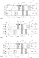
- FIG. 1-3 is disclosed an Air Handling Unit (AHU) 1 according to an embodiment of the invention.
- the AHU 1 comprises a supply air channel 2 having a supply air inlet 2a and a supply air outlet 2b for delivering fresh air to an air ventilation system in a building.
- the AHU further comprises an extract air channel 3 having an extract air inlet 3a receiving exhaust air, also commonly called extract air or indoor air, and guiding the exhaust air to the outside through an extract air outlet 3b.
- exhaust air also commonly called extract air or indoor air
- the left side of the AHU in the figures is intended to be connected to the surroundings or outdoor while the right side of the figures is intended to be connected to an air ventilation system in a building for distribution of fresh air to the building and extraction of exhaust air from the interior of the building.
- the AHU 1 In order to control the air flow in the supply air channel 2 is the AHU 1 provided with a supply air damper 4a in the supply air channel 2 close to the supply air outlet 2b.
- the extract air channel 3 provided with an extract air damper 4b close to the extract air outlet 3b in order to control the flow of exhaust air in the extract air channel 3.
- the AHU is further provided with a heat exchanger 5, which for example may be a heat exchanger wheel, which is located to be in contact with and exchange heat between the flows of air in the supply air channel 2 and extract air channel 3.
- the AHU 1 also comprises a heat pump system 6 having a first media phase change unit 6a located in the supply air channel 2 and a second media phase change unit 6b located in the extract air channel 3.
- the heat pump system 6 transfers heat between the flow of air in the supply air channel 2 and extract air channel 3. Heat is transferred by using a heat transfer media which may evaporate and condense in the first and second media phase change units 6a, 6b. Hence, the media phase change units 6a, 6b may shift between working as evaporator and condenser such that the heat pump system 6 function as a reversible heat pump and may be controlled to transfer heat in either direction, i.e. transfer heat to the air flow in the supply air channel 2 from the air flow in the extract air channel 3 or vice versa. As can be seen in the figures, the first and second media phase change units 6a, 6b are located downstream of the heat exchanger 5 in the supply air channel 2 as well as the extract air channel 3.
- the AHU is further provided with a short cut connection 7 through which air may flow between the supply air channel 2 and extract air channel 3.
- the air flow through the shirt cut connection 7 is controlled by a short cut damper 8.
- the shortcut connection 7 connects the supply air channel 2 upstream of the heat exchanger 5 and the first media phase change unit 6a with the extract air channel 3 downstream of the heat exchanger 5 the second media phase change unit 6a.
- the AHU 1 is also connected to an Electronic Control Unit (ECU) 9 which may be connected to relevant features in order to receive control inputs and measured data of relevant parameters or to output relevant control instructions to flow control devices.
- ECU Electronic Control Unit
- the ECU may receive inputs such as measurements from pressure indicating means 10, thermometers (not shown), humidity sensors (not shown) or control inputs from an input unit or remote control.
- the ECU 9 may also send control outputs to flow controllers such as the supply air damper 4a, the extract air damper 4b, the short cut damper 8, a supply air fan 11a or an extract air fan 11b as well as control instructions to the heat pump system 6 or heat exchanger 5.
- Figures 1-3 disclose the same embodiment of the AHU 1 but disclosing the AHU 1 to be controlled differently in order to be in a heat recovery mode ( figure 1 ) or in a defrost mode ( figures 2 and 3 ).
- Figure 1 thus discloses the AHU being in a heat recovery mode, i.e. a mode in which heat from the exhaust air in the extract air channel 3 is transferred to the air flowing into a building via the supply air channel 2. Heat is transferred via the heat exchanger 5 and the heat pump system 6.
- the heat pump system 6 is controlled by the ECU 9 such that the first media phase change unit 6a in the supply air channel 2 is working as a condenser and thus releasing heat to the surrounding air and the second media phase change unit 6b in the extract air channel 3 is working as an evaporator thus absorbing heat from the exhaust air.
- the indoor air leaving the building via the extract air channel 3 will first be cooled down in the heat exchanger 5, e.g. to a temperature close to zero degrees or even somewhat below, before continuing to the second media phase change unit 6b in the heat pump system 6.
- the second media phase change unit 6b which functions as an evaporator, and further cools the exhaust air to temperatures well below zero degrees Celsius, will the water content in the exhaust air condense and start to freeze on the cold surface of the second media phase change unit 6b.
- the initiation of a defrost cycle may for example be controlled by detecting the pressure drop over the second media phase change unit 6b by the pressure drop estimating means 10, which for example may be a pressure sensor upstream of respectively a pressure sensor downstream of the second media phase change unit 6b which thus may easily be used by the ECU to calculate the pressure drop and when the pressure drop is above a certain limit should there be a signal sent indicating a change to defrost mode should occur.
- the pressure drop estimating means 10 which for example may be a pressure sensor upstream of respectively a pressure sensor downstream of the second media phase change unit 6b which thus may easily be used by the ECU to calculate the pressure drop and when the pressure drop is above a certain limit should there be a signal sent indicating a change to defrost mode should occur.
- FIG 2 is shown how a defrost mode or defrost cycle may be performed.
- the short cut connection 7 has been fully opened by the short cut damper 8 switching to its second, open position (II) and both the supply air damper 4a and extract air damper 4b in the supply air channel 2 respectively extract air channel 3 have been completely switched and are now in the second, closed position.
- II second, open position
- both the supply air damper 4a and extract air damper 4b in the supply air channel 2 respectively extract air channel 3 have been completely switched and are now in the second, closed position.
- the air flow of exhaust air is thereafter guided to the supply air channel 2 via the short cut connection 7 in order to flow through the heat exchanger once more but now on the supply air channel 2 side before the flow continues to the first media phase change unit 6b now working as evaporator in order to cold the air flow passing by.
- This mode will thus enable a heating operation of the second media phase change unit 6b working both from the outside and inside.
- the exhaust air will heat on the outside by the relatively hot flow of exhaust air, which no longer will be significantly cooled in the heat exchanger 5 before reaching the second media phase change unit 6b, since there is no fresh, cool supply air entering the AHU 1.
- the reversal of the heat pump system will heat the second media phase change unit 6b from the inside by condensing the cooling media inside.
- the defrost mode will continue until there is a control signal from the ECU indicating that the heat pump system 5 has been defrosted.
- the ECU 9 is thus sending a signal that the operation of AHU should be returned to heat recovery operation.
- figure 3 is disclosed how the supply air damper 4a in the supply air inlet 2a as well as the extract air damper 4b in the extract air channel 3 are set in the first, open position (I) allowing cold supply air to enter as disclosed in figure 3 which is the normal position in heat recovery mode.
- I open position
- the ECU 9 send a signal to set the short cut damper 8 in a transition mode (III) in which the short cut damper 8 will oscillate between being open and closed. This is illustrated by using dashed lines for the short cut damper 8 indicating two different positions between which the short cut damper oscillates.
- the transition mode will continue for a while until it is considered that there will be no more risk for freezing and the damper get stuck in a closed position where after the operational mode of the AHU will be the normal heat recovery mode as disclosed in figure 1 .
- FIG 1-3 is disclosed an embodiment in which the operation of a damper in a transition mode (III) may be beneficial. It is an essential feature of the invention that the ECU 9 is programmed to set the damper 8 in said transition mode (III) after there has been a defrost cycle performed in the AHU 1.
- a rotational damper 408 could be controlled by an ECU (not shown) to switch from being in a first, open position (I) in figure 4a to a second, closed position (II) in figure 4c via a transition mode (III) disclosed in figure 4b .
- the damper 408 will oscillate between an open position and a closed position for a while until there is no risk for the damper being stuck in its second, closed position (II).
- figure 5 is disclosed the change of a sliding damper to switch from being in a first, open position (I) in figure 5a to a second, closed position (II) in figure 5c via a transition mode (III) disclosed in figure 4b .
- the damper 508 will oscillate between an open position and a closed position for a while until there is no risk for the damper being stuck in its second, closed position (II). It may even be possible that the damper 508 may oscillate back and forth while being closed if there is enough space to move without causing the holes to overlap.
Landscapes
- Engineering & Computer Science (AREA)
- Chemical & Material Sciences (AREA)
- Combustion & Propulsion (AREA)
- Mechanical Engineering (AREA)
- General Engineering & Computer Science (AREA)
- Air Conditioning Control Device (AREA)
- Air-Flow Control Members (AREA)
Description
- The present invention relates to an Air Handling Unit providing fresh air to a building. The invention is in particular directed to the feature of making the air flow control more reliable in such a unit or system.
- In offices and other larger premises, there is often a need to be able to control the indoor climate separately in different parts of the premises or in individual rooms. An accurate local temperature and ventilation control is required to ensure a sufficient comfort level for the persons present in a building. Also heat generated by electric appliances and heat and exhaled air generated by persons inside the building have to be taken into account for the control. Together with the prevailing weather conditions, these factors have a large influence on the instantaneous demand for heating, cooling and ventilation capacity. In order to improve the comfort climate indoors the building could be provided with an Air handling Unit (AHU) for exhausting and supplying air to a Heating, Ventilation and Air Conditioning (HVAC) system. Similar systems has lately been more commonly used also in smaller buildings, e.g. family houses, as there is a desire for better insulation and thus also a need for a forced change of air in these buildings. In order to improve the energy efficiency of buildings using air conditioning systems with controlled air intake/air outlet is there a desire to lower heat losses by exhausting warm air to the outside and reduce heat losses by heat exchanging exhaust air with fresh air, e.g. in a heat recovery arrangement in the AHU. In systems for controlling the indoor climate in buildings, it is common that at least one heat exchanger is arranged in connection with the extract air duct. Such a heat exchanger can, for example, be a cross-flow or counter-flow heat exchanger (also called plate heat exchangers), and can be used for reducing the total energy consumption of the system by recovering a portion of the heat energy from the exhaust air before it is discharged. Thus, such a heat exchanger in connection with the extract air duct transfers heat energy from the exhaust air flowing out to the outdoor air flowing in. In certain conditions, frost or ice may form on the heat exchanger, which then has to go through a defrost cycle, during which the heat exchanger is heated to melt the ice. One way of performing defrosting (or deicing) of the extract air duct heat exchanger is to use the hot airflow leaving the building for heating and defrosting. In this case is the cold flow usually restricted or completely shut off in the part of the heat exchanger which shall be defrosted. Such a system is for example described in
EP 2 546 581WO 01/22021 - The patent document
US 2002/164944 teaches a ventilator device and method in which a heat exchanger is used to selectively transfer heat between fresh outside air entering and exhaust air leaving an enclosed space, when energy can be recovered from the exhaust air by doing so. - Furthermore, the patent document
WO 2011/022331 teaches a transport refrigeration unit which comprises a damper assembly which is configured to operatively block an airflow in a defrost mode. - In order to make the system perform as desired it is vital to have a robust and reliable flow control system which control the airflows as desired and may change the air flows when switching between different modes, e.g. a heat recovery mode and a defrost mode, or different demand of air exchange in a building. In order to control the air flow in the AHU and HVAC they are generally provided with a multitude of dampers and fans in order to control the air flow and directing the desired quantity of air with a required quality to and from different locations. The failure of a damper or fan to function could be fatal to the efficiency of the AHU and the HVAC system and the possibility for an efficient heat recovery and air quality control. Even though the AHUs and HVACs today normally function well are there still some features in the damper arrangements which may be improved in order to ensure their functionality.
- There is therefore a desire for an improved flow control arrangement and device in order to provide a more robust and efficient air flow control system.
- The invention is directed to solve a problem concerning the control of dampers which has been identified when developing Air Handling Units (AHUs) adapted for cold climates. The problem is that a damper may get stuck in a position due to ice formation. The reasons for why a damper may get stuck from ice formation may be due to several factors. For example, in cold climates there is a particular need for making the heat recovery function as efficient as possible in order to avoid significant heat losses due to ventilation of warm exhaust air and intake of cold supply air into a building. However, the development of such devices also has the effect that some portions in the heat recovery arrangement may have low temperatures, below zero, and thus cause the water in the air to condense and freeze. The cold outside air is in general not a problem concerning condensing and ice formation since it in many cases is rather dry, at least when the temperature is well below zero, and is subjected to a heating operation enabling a higher water content to be present in the air. In general, the risk for ice formation increases with the efficiency of the heat recovery arrangement since the more efficient the heat recovery arrangement is, the more will the warm side (the side from which heat is exhausted) in the heat arrangement be cooled down. To be noted, this air stream which will be cooled down is the exhaust air which in general is warm and humid. Furthermore, a heat recovery arrangement will also be more vulnerable concerning ice formation when the temperatures decreases of the airflows since the system will work at lower temperatures generally. Hence, the desire for an increased efficiency in the system at low temperature as well as the low temperature itself contributes to an increased risk for ice formation in a heat recovery system.
- In order to get rid of the ice formed in the AHU or HVAC could there be a defrost operation as described in
EP 2 546 581WO 01/22021 - In summary, the invention relates to an air handling unit (AHU) in accordance with the features of appended
claim 1 and a method for controlling a short cut damper in an air handling unit in accordance with the features of appended claim 11. Preferred embodiments are defined in the dependent claims. - The damper arrangement comprises a damper and an Electronic Control Unit (ECU). The ECU may be a local ECU located on or in the vicinity of the damper or being more distant, e.g. forming part of a centralized control system. The ECU could be dedicated to only control the damper, control a group of dampers or control further elements or even the AHU or the HVAC system.
- The ECU is programmed to control the damper when the damper is changed from being in a first, open position (I) to a second, closed position (II) to be in a transition mode (III) before it will be in the second, closed position (II). The ECU is programmed to control the damper to oscillate or vibrate when the damper is in its transition mode (III). The transition mode (III) could for example set the damper to oscillate between being closed and open. Alternatively, the oscillations in the transition mode (III) could also be made by causing the damper to vibrate while the damper is in its closed position. It is an essential feature of the invention that said ECU is programmed to set the damper in said transition mode (III) after there has been a defrost cycle performed in the AHU.
- The vibrations or oscillations are intended to avoid the damper to be stuck due to freezing. The oscillations and vibrations may differ depending on the design of the damper. In some cases the dampers move rather slowly and there may be a cycle of almost a minute to perform an opening and closing action of the damper. In general, the damper needs not to be fully opened when being oscillated between open and closed positions but the damper should be opened up such that there is no risk for contact surfaces between the damper plate and the edges of the air channel to be stuck to each other due to a freezing action. The ECU may be programmed to set the damper in the transition state for any desired time period, e.g. between 1 and 10 minutes.
- The damper arrangement could be used for a damper comprised in an Air Handling Unit (AHU). The AHU comprises an extract air channel comprising at least one extract air inlet for guiding exhaust air from a building to the outside through at least one extract air outlet and a supply air channel comprising at least one supply air inlet for guiding fresh air from the outdoor into a building through at least one supply air outlet. The extract air channel and supply air channel are in a heat exchanging relation to each other via a heat exchanger.
- The damper arrangement is working as a short cut damper which controls a flow in a shortcut connection between the extract air channel and the supply air channel. For example, the ECU could be programmed set the short cut damper in a first, essentially open position (I) and the extract air damper and supply air damper to be in a second, closed position (II) when the AHU (1) is working in a defrost mode. When the defrost mode is ended and the AHU (1) is changed to function in a heat recovery mode, the extract air damper and supply air damper are changed to be in a first, essentially open position (I) and the short cut damper to be set in a transition mode (III) before being set in a second, closed position (II).
- In general, the risk for ice formation and that a damper get stuck in the system due to freezing is in particular high when there is a drastic change of temperatures in different parts of the air ventilation system and when a damper is set to a closed position. Hence, if a damper arrangement is comprised in an Air Handling Unit (AHU), the ECU could be connected to one or several temperatures sensors or temperature estimating means for estimating the temperature in the vicinity of the damper arrangement. The ECU could in this case be programmed to only control the damper arrangement to be in the transition mode (III) when there is an estimated risk for a temperature to be below zero degrees in the vicinity of the damper. To be noted, the actual temperature of the air may be above zero while there still is a risk for ice formation on surfaces which may be below zero.
- Still a further parameter which is of interest for the risk of ice formation is the humidity in the air. Hence, the ECU could be connected to a humidity sensor or a humidity estimating means and is programmed to set the damper in said transition mode (III) in dependence of the humidity. It may of course be possible to use both the humidity values and temperatures in order to evaluate if the damper should be set in the transition mode (III).
- When there is a defrost cycle performed in the AHU or in the HVAC system, there is a particularly high risk for a damper to be stuck in a closed position after the defrosting is performed. During the defrost operation, the temperature is elevated, which thus allows a higher water content in the air, while at the same time ice is melted which in general contributes to more water being present in the air. A generally higher moisture content of the air passing through the AHU may also be due to recirculation of humid exhaust air in the AHU. Hence, the ECU could be programmed to set the damper in the transition mode (III) after there has been a defrost cycle performed in the AHU or in some part of the HVAC system.
- In addition to set the damper arrangement in the transition mode could the damper be arranged such that the material of the damper and/or the edges of the air duct which forms the contact surfaces are made from a hydrophobic material and having a surface with hydrophobic properties, e.g. silicone.
- As previously briefly discussed, the time period for how long the damper arrangement should be in the transition mode (III) may be hard to decide. In many cases, the time period will be set to a threshold value which by testing and operation of the damper arrangement may be adjusted and improved. The time period could for example be dependent on temperatures and humidity. Still another method for deciding when to end the transition mode (III) could be to program the ECU to lift the damper from its closed position to its open position with a predefined time interval and increasing the time interval as long as the force needed to lift the damper to an open position is essentially the same. Hence, when there is an ice formation on the contact surfaces will there be a stronger force needed to separate the damper from the contact surface. If the force needed to perform an opening, oscillation or vibration of the damper is essentially constant, there should be no water present which freezes between the contact surfaces and the next opening, oscillation or vibration could be performed after a somewhat longer period. Furthermore, the ECU could be programmed to in its transition mode to lift the damper from its closed position to its open position with a predefined time interval, said time decreasing when the force needed to lift the damper to an open position is increasing in order to prevent the damper from being stuck due to ice formation. An increased force needed to open or oscillate the damper indicates that ice have been formed on the contact surfaces.
- As previously disclosed, a damper is particularly vulnerable to be stuck by ice formation after a defrost operation has been performed due to release of water in the system and an increased temperature. The damper arrangement is thus in particular suitable for a damper located in an air channel which receives an air flow from a feature which is defrosted during a defrost mode, in particular for a damper which is open during the defrost operation and thereafter closed.
- The invention also relates to a method for controlling a short cut damper in accordance with the features of appended
claim 8. The damper is controlled to be in a transition mode (III), in which the damper is set to oscillate or vibrate, before the damper is set to be in a second, closed position (II) when changing from being in a first, open position (I) to a second, closed position (II) after there has been a defrost cycle performed in the AHU. - The present invention will now be described more in detail with reference to the appended drawings, where:
- Figure 1
- discloses an Air Handling Unit (AHU) in heat recovery mode provided with damper arrangements
- Figure 2
- discloses the AHU from
figure 1 in defrost mode - Figure 3
- discloses the AHU from
figure 1 provided with damper arrangements being in a transition mode (III) - Figure 4
- discloses a rotating damper arrangement changing from a first, open position (I) to a second, closed position (II) via a transition mode (III) with oscillating dampers.
- Figure 5
- discloses a sliding damper arrangement changing from a first, open position (I) to a second, closed position (II) via a transition mode (III) with oscillating dampers.
- In
figures 1-3 is disclosed an Air Handling Unit (AHU) 1 according to an embodiment of the invention. TheAHU 1 comprises asupply air channel 2 having asupply air inlet 2a and asupply air outlet 2b for delivering fresh air to an air ventilation system in a building. The AHU further comprises anextract air channel 3 having anextract air inlet 3a receiving exhaust air, also commonly called extract air or indoor air, and guiding the exhaust air to the outside through anextract air outlet 3b. Hence, the left side of the AHU in the figures is intended to be connected to the surroundings or outdoor while the right side of the figures is intended to be connected to an air ventilation system in a building for distribution of fresh air to the building and extraction of exhaust air from the interior of the building. In order to control the air flow in thesupply air channel 2 is theAHU 1 provided with asupply air damper 4a in thesupply air channel 2 close to thesupply air outlet 2b. In a similar way is theextract air channel 3 provided with anextract air damper 4b close to theextract air outlet 3b in order to control the flow of exhaust air in theextract air channel 3. The AHU is further provided with aheat exchanger 5, which for example may be a heat exchanger wheel, which is located to be in contact with and exchange heat between the flows of air in thesupply air channel 2 and extractair channel 3. TheAHU 1 also comprises a heat pump system 6 having a first mediaphase change unit 6a located in thesupply air channel 2 and a second mediaphase change unit 6b located in theextract air channel 3. The heat pump system 6 transfers heat between the flow of air in thesupply air channel 2 and extractair channel 3. Heat is transferred by using a heat transfer media which may evaporate and condense in the first and second mediaphase change units phase change units supply air channel 2 from the air flow in theextract air channel 3 or vice versa. As can be seen in the figures, the first and second mediaphase change units heat exchanger 5 in thesupply air channel 2 as well as theextract air channel 3. - The AHU is further provided with a
short cut connection 7 through which air may flow between thesupply air channel 2 and extractair channel 3. The air flow through the shirt cutconnection 7 is controlled by ashort cut damper 8. Theshortcut connection 7 connects thesupply air channel 2 upstream of theheat exchanger 5 and the first mediaphase change unit 6a with theextract air channel 3 downstream of theheat exchanger 5 the second mediaphase change unit 6a. - The
AHU 1 is also connected to an Electronic Control Unit (ECU) 9 which may be connected to relevant features in order to receive control inputs and measured data of relevant parameters or to output relevant control instructions to flow control devices. For example, the ECU may receive inputs such as measurements from pressure indicating means 10, thermometers (not shown), humidity sensors (not shown) or control inputs from an input unit or remote control. TheECU 9 may also send control outputs to flow controllers such as thesupply air damper 4a, theextract air damper 4b, theshort cut damper 8, asupply air fan 11a or anextract air fan 11b as well as control instructions to the heat pump system 6 orheat exchanger 5. -
Figures 1-3 disclose the same embodiment of theAHU 1 but disclosing theAHU 1 to be controlled differently in order to be in a heat recovery mode (figure 1 ) or in a defrost mode (figures 2 and 3 ). -
Figure 1 thus discloses the AHU being in a heat recovery mode, i.e. a mode in which heat from the exhaust air in theextract air channel 3 is transferred to the air flowing into a building via thesupply air channel 2. Heat is transferred via theheat exchanger 5 and the heat pump system 6. The heat pump system 6 is controlled by theECU 9 such that the first mediaphase change unit 6a in thesupply air channel 2 is working as a condenser and thus releasing heat to the surrounding air and the second mediaphase change unit 6b in theextract air channel 3 is working as an evaporator thus absorbing heat from the exhaust air. - In this heat recovery mode, according to
figure 1 , is theshort cut connection 7 closed by theshort cut valve 8 being in a second, closed position (II) while both thesupply air damper 4a and extractair damper 4b in thesupply air channel 2 respectively extractair channel 3 are in a first, open position (I). - If this mode is used during winter time, e.g. having an outdoor temperature below zero degrees, and wanting an indoor temperature of about 20 degrees, the indoor air leaving the building via the
extract air channel 3 will first be cooled down in theheat exchanger 5, e.g. to a temperature close to zero degrees or even somewhat below, before continuing to the second mediaphase change unit 6b in the heat pump system 6. When the air comes in contact with the second mediaphase change unit 6b, which functions as an evaporator, and further cools the exhaust air to temperatures well below zero degrees Celsius, will the water content in the exhaust air condense and start to freeze on the cold surface of the second mediaphase change unit 6b. As the time passes will the layer of ice grow thicker on the second mediaphase change unit 6b and when sufficient time have passed will there be an ice layer which significantly decreases the heat exchange function in the heat pump and thus the overall efficiency of the AHU while also increasing the pressure drop over the second mediaphase change unit 6b. The initiation of a defrost cycle may for example be controlled by detecting the pressure drop over the second mediaphase change unit 6b by the pressure drop estimating means 10, which for example may be a pressure sensor upstream of respectively a pressure sensor downstream of the second mediaphase change unit 6b which thus may easily be used by the ECU to calculate the pressure drop and when the pressure drop is above a certain limit should there be a signal sent indicating a change to defrost mode should occur. - In
figure 2 is shown how a defrost mode or defrost cycle may be performed. Theshort cut connection 7 has been fully opened by theshort cut damper 8 switching to its second, open position (II) and both thesupply air damper 4a and extractair damper 4b in thesupply air channel 2 respectively extractair channel 3 have been completely switched and are now in the second, closed position. Hence, there will be no flow of fresh, supply air in the AHU in this mode disclosed infigure 2 but only recirculation of exhaust air entering through theextract channel inlet 3a, passing theheat exchanger 5 and the second mediaphase change unit 6b, now switched to function as evaporator in order to heat the surroundings. The air flow of exhaust air is thereafter guided to thesupply air channel 2 via theshort cut connection 7 in order to flow through the heat exchanger once more but now on thesupply air channel 2 side before the flow continues to the first mediaphase change unit 6b now working as evaporator in order to cold the air flow passing by. - This mode will thus enable a heating operation of the second media
phase change unit 6b working both from the outside and inside. The exhaust air will heat on the outside by the relatively hot flow of exhaust air, which no longer will be significantly cooled in theheat exchanger 5 before reaching the second mediaphase change unit 6b, since there is no fresh, cool supply air entering theAHU 1. In addition, the reversal of the heat pump system will heat the second mediaphase change unit 6b from the inside by condensing the cooling media inside. The defrost mode will continue until there is a control signal from the ECU indicating that theheat pump system 5 has been defrosted. TheECU 9 is thus sending a signal that the operation of AHU should be returned to heat recovery operation. However, after the defrost operation has ended it is very possible that there is a high degree of humidity in the air comprised in theAHU 1. - In
figure 3 is disclosed how thesupply air damper 4a in thesupply air inlet 2a as well as theextract air damper 4b in theextract air channel 3 are set in the first, open position (I) allowing cold supply air to enter as disclosed infigure 3 which is the normal position in heat recovery mode. However, since it is expected that the air is rather humid and the switch of operation from defrost mode to heat recovery mode will there be a great chance of freezing of water condensed from the air. This could cause a freezing of air condensed on the contact surfaces of theshort cut damper 8 and theshort cut connection 7. In order to avoid theshort cut damper 8 to get stuck in the second, closed position (II) will theECU 9 send a signal to set theshort cut damper 8 in a transition mode (III) in which theshort cut damper 8 will oscillate between being open and closed. This is illustrated by using dashed lines for theshort cut damper 8 indicating two different positions between which the short cut damper oscillates. The transition mode will continue for a while until it is considered that there will be no more risk for freezing and the damper get stuck in a closed position where after the operational mode of the AHU will be the normal heat recovery mode as disclosed infigure 1 . - In
figure 1-3 is disclosed an embodiment in which the operation of a damper in a transition mode (III) may be beneficial. It is an essential feature of the invention that theECU 9 is programmed to set thedamper 8 in said transition mode (III) after there has been a defrost cycle performed in theAHU 1. - In
figure 4 is disclosed how arotational damper 408 could be controlled by an ECU (not shown) to switch from being in a first, open position (I) infigure 4a to a second, closed position (II) infigure 4c via a transition mode (III) disclosed infigure 4b . Thedamper 408 will oscillate between an open position and a closed position for a while until there is no risk for the damper being stuck in its second, closed position (II). - In
figure 5 is disclosed the change of a sliding damper to switch from being in a first, open position (I) infigure 5a to a second, closed position (II) infigure 5c via a transition mode (III) disclosed infigure 4b . Thedamper 508 will oscillate between an open position and a closed position for a while until there is no risk for the damper being stuck in its second, closed position (II). It may even be possible that thedamper 508 may oscillate back and forth while being closed if there is enough space to move without causing the holes to overlap.
Claims (11)
- An Air Handling Unit, AHU, (1) for a building having an extract air channel (3) comprising at least one extract air inlet (3a) for guiding exhaust air from a building to the outside through at least one extract air outlet (3b) and a supply air channel (2) comprising at least one supply air inlet (2a) for guiding fresh air from the outdoor into a building through at least one supply air outlet (2b), said extract air channel (3) and said supply air channel (2) being in a heat exchanging relation to each other via a heat exchanger (5), said AHU (1) further comprising a damper arrangement comprising a short cut damper (8) which controls a flow in a shortcut connection (7) between the extract air channel (3) and the supply air channel (2) and an Electronic Control Unit (ECU) (9) characterized in that
said ECU (9) is programmed to control the short cut damper ( 8) when the short cut damper (8) is changed from being in a first, open position (I) to a second, closed position (II) to be in a transition mode (III) before it will be in the second, closed position (II), said transition mode (III) being programmed to set the short cut damper (8) to oscillate or vibrate after there has been a defrost cycle performed in the AHU (1). - An AHU (1) according to claim 1 characterized in that the damper arrangement includes an extract air damper (4b) in order to control the air flow in the extract air channel (3) or a supply air damper (4a) in order to control the air flow in the supply air channel (2).
- An AHU (1) according to claim 2 characterized in that said ECU (9) is programmed to set the short cut damper (8) in a first, essentially open position (I) and the extract air damper (4b) and supply air damper (4a) to be in a second, closed position (II) when the AHU (1) is working in a defrost mode and to set the extract air damper (4b) and supply air damper (4a) to be in a first, essentially open position (I) when the AHU (1) changes to a heat recovery mode and the short cut damper (8) to be in a transition mode (III) before being set in a second, closed position (II).
- An AHU (1) according to any previous claim characterized in that said ECU (9) is connected to one or several temperatures sensors or temperature estimating means for estimating the temperature in the vicinity of said short cut damper (8), said ECU (9) programmed to only control the short cut damper (8) to be in said transition mode (III) when there is an estimated risk for a temperature to be below zero degrees in the vicinity of the short cut damper (8, 408, 508).
- An AHU (1) according to any previous claim characterized in that said ECU (9) is connected to a humidity sensor or humidity estimating means and is programmed to set the short cut damper (8, 408, 508) in said transition mode (III) in dependence of the humidity.
- An AHU (1) according to claim 4 and 5 characterized in that said ECU (9) is programmed to set the short cut damper (8, 408, 508) in said transition mode (III) in dependence of the humidity and the temperature.
- An AHU (1) according to any previous claim characterized in that the material of contact surfaces of the short cut damper (8, 408, 508) and/or the contact surfaces are made from a hydrophobic material.
- An AHU (1) according to any previous claim characterized in that the ECU (9) is programmed in its transition mode (III) to lift the short cut damper (8, 408, 508) from its closed position to its open position with a predefined time interval, said time interval increasing as long as the force needed to lift the damper to an open position is essentially the same.
- An AHU (1) according to claim 8 characterized in that the ECU (102) is programmed in its transition mode (III) to lift the short cut damper (8) from its closed position to its open position with a predefined time interval, said time interval decreasing when the force needed to lift the damper to an open position is increasing.
- An AHU (1) according to any previous claim characterized in that the short cut damper (8, 408, 508) is located in an air channel (2, 3) which receives an air flow from a feature which is defrosted during a defrost mode.
- A method for controlling a short cut damper (8, 408, 508) in an Air Handling Unit, AHU, (1) for a building, said short cut damper (8, 408, 508) being controllable to change from being in a first, open position (I) to a second, closed position (II)
characterized in that
the short cut damper (8, 408, 508) is controlled to be in a transition mode (III), in which the short cut damper (8, 408, 508) is set to oscillate or vibrate, before the short cut damper (8, 408, 508) is set to be in said second, closed position (II) when changing from being in the first, open position (I) to the second, closed position (II) after there has been a defrost cycle performed in the AHU (1).
Applications Claiming Priority (2)
| Application Number | Priority Date | Filing Date | Title |
|---|---|---|---|
| SE1751304A SE542351C2 (en) | 2017-10-20 | 2017-10-20 | Flow control arrangement for an air ventilation system |
| PCT/SE2018/051054 WO2019078774A1 (en) | 2017-10-20 | 2018-10-17 | Flow control arrangement for an air ventilation system |
Publications (3)
| Publication Number | Publication Date |
|---|---|
| EP3698087A1 EP3698087A1 (en) | 2020-08-26 |
| EP3698087A4 EP3698087A4 (en) | 2021-07-21 |
| EP3698087B1 true EP3698087B1 (en) | 2023-07-19 |
Family
ID=66174541
Family Applications (1)
| Application Number | Title | Priority Date | Filing Date |
|---|---|---|---|
| EP18869148.9A Active EP3698087B1 (en) | 2017-10-20 | 2018-10-17 | Flow control arrangement for an air ventilation system |
Country Status (5)
| Country | Link |
|---|---|
| EP (1) | EP3698087B1 (en) |
| DK (1) | DK3698087T3 (en) |
| FI (1) | FI3698087T3 (en) |
| SE (1) | SE542351C2 (en) |
| WO (1) | WO2019078774A1 (en) |
Families Citing this family (3)
| Publication number | Priority date | Publication date | Assignee | Title |
|---|---|---|---|---|
| CZ308293B6 (en) * | 2018-12-27 | 2020-04-22 | Mirai Intex Sagl | Dehumidifier, in particular for air cooling or air-conditioning machines |
| DE102019008629A1 (en) * | 2019-12-13 | 2021-06-17 | Truma Gerätetechnik GmbH & Co. KG | Air distributor and heater |
| IT202200000068A1 (en) * | 2022-01-04 | 2023-07-04 | Pv Solutions S R L S | EQUIPMENT FOR AIR TREATMENT IN BUILDINGS AND RELATED USE PROCEDURE |
Family Cites Families (10)
| Publication number | Priority date | Publication date | Assignee | Title |
|---|---|---|---|---|
| JPS5847Y2 (en) * | 1979-07-04 | 1983-01-05 | 株式会社 東洋製作所 | Closure damper antifreeze device for alternate switching operation air conditioner |
| US5375413A (en) * | 1994-01-07 | 1994-12-27 | Paragon Electric Company, Inc. | Air baffle apparatus |
| US7231967B2 (en) * | 1994-01-31 | 2007-06-19 | Building Performance Equipment, Inc. | Ventilator system and method |
| NO310321B1 (en) | 1999-09-20 | 2001-06-18 | Villavent As | A method for defrosting a counter-current type heat exchanger and assembly comprising a heat exchanger in the form of such a counter-current heat exchanger |
| EP1962030B1 (en) * | 2005-12-14 | 2014-03-12 | Panasonic Corporation | Heat exchange type ventilator |
| DE102006001679B4 (en) * | 2006-01-12 | 2008-01-31 | Emz-Hanauer Gmbh & Co. Kgaa | Air damper device for a refrigerator or freezer of the kitchen equipment |
| US9052131B2 (en) * | 2009-08-18 | 2015-06-09 | Carrier Corporation | Damper apparatus for transport refrigeration system, transport refrigeration unit, and methods for same |
| SE536208E (en) | 2011-07-15 | 2017-03-07 | Iv Produkt Ab | Air treatment system and ways to control the defrosting of this |
| DE202012001761U1 (en) * | 2012-02-23 | 2012-04-26 | Reventa Kunststoffverarbeitung Gmbh & Co. Kg | Air supply |
| US9737916B2 (en) * | 2015-08-24 | 2017-08-22 | Lockheed Martin Corporation | Dynamic resonance system and method for the anti-icing and de-icing of inlet grids |
-
2017
- 2017-10-20 SE SE1751304A patent/SE542351C2/en unknown
-
2018
- 2018-10-17 EP EP18869148.9A patent/EP3698087B1/en active Active
- 2018-10-17 DK DK18869148.9T patent/DK3698087T3/en active
- 2018-10-17 FI FIEP18869148.9T patent/FI3698087T3/en active
- 2018-10-17 WO PCT/SE2018/051054 patent/WO2019078774A1/en not_active Ceased
Also Published As
| Publication number | Publication date |
|---|---|
| SE1751304A1 (en) | 2019-04-21 |
| EP3698087A4 (en) | 2021-07-21 |
| EP3698087A1 (en) | 2020-08-26 |
| FI3698087T3 (en) | 2023-10-18 |
| SE542351C2 (en) | 2020-04-14 |
| WO2019078774A1 (en) | 2019-04-25 |
| DK3698087T3 (en) | 2023-10-16 |
Similar Documents
| Publication | Publication Date | Title |
|---|---|---|
| JP5709993B2 (en) | Refrigeration air conditioner | |
| EP3698088B1 (en) | An air handling unit for a ventilation system in a building and a method for performing a defrosting operation of an air handling unit | |
| JP5958503B2 (en) | Room temperature adjustment system | |
| EP3633273A1 (en) | Air conditioner | |
| CN103797308B (en) | Refrigerating air conditioning device | |
| CN112880132A (en) | Method and device for defrosting control of air conditioning system and air conditioning system | |
| CN107152819A (en) | Air-conditioning device and its control method | |
| JP4518998B2 (en) | Heat pump air conditioner | |
| CN107101275A (en) | A kind of air conditioner and its control method | |
| US20200300513A1 (en) | Refrigeration cycle apparatus | |
| JP2010121789A (en) | Air conditioner | |
| CN201621793U (en) | A frequency conversion refrigeration dehumidifier | |
| CN111059633A (en) | Dehumidification method of air conditioning system | |
| EP3207315B1 (en) | Adaptive defrosting of an air treatment system | |
| CN110873426A (en) | Air conditioner and self-cleaning control method thereof | |
| CN110030705A (en) | The control method of multi-line system | |
| WO2019078774A1 (en) | Flow control arrangement for an air ventilation system | |
| CN107726536A (en) | Air-conditioning and its outdoor machine frost eliminating method | |
| CN206919275U (en) | A kind of air conditioner | |
| JP6313021B2 (en) | Air conditioner | |
| CN110762746B (en) | Air conditioner and defrosting control method thereof | |
| SE542349C2 (en) | Method for defrosting of an Air Handling Unit | |
| CN103983059A (en) | Air conditioning system and control method thereof | |
| JP4622901B2 (en) | Air conditioner | |
| CN108266931B (en) | Thermal management system and control method thereof |
Legal Events
| Date | Code | Title | Description |
|---|---|---|---|
| STAA | Information on the status of an ep patent application or granted ep patent |
Free format text: STATUS: THE INTERNATIONAL PUBLICATION HAS BEEN MADE |
|
| PUAI | Public reference made under article 153(3) epc to a published international application that has entered the european phase |
Free format text: ORIGINAL CODE: 0009012 |
|
| STAA | Information on the status of an ep patent application or granted ep patent |
Free format text: STATUS: REQUEST FOR EXAMINATION WAS MADE |
|
| 17P | Request for examination filed |
Effective date: 20200508 |
|
| AK | Designated contracting states |
Kind code of ref document: A1 Designated state(s): AL AT BE BG CH CY CZ DE DK EE ES FI FR GB GR HR HU IE IS IT LI LT LU LV MC MK MT NL NO PL PT RO RS SE SI SK SM TR |
|
| AX | Request for extension of the european patent |
Extension state: BA ME |
|
| DAV | Request for validation of the european patent (deleted) | ||
| DAX | Request for extension of the european patent (deleted) | ||
| A4 | Supplementary search report drawn up and despatched |
Effective date: 20210617 |
|
| RIC1 | Information provided on ipc code assigned before grant |
Ipc: F24F 11/41 20180101AFI20210611BHEP Ipc: F24F 13/10 20060101ALI20210611BHEP Ipc: F24F 12/00 20060101ALI20210611BHEP Ipc: F24F 13/12 20060101ALI20210611BHEP Ipc: F24F 11/81 20180101ALI20210611BHEP Ipc: F24F 110/10 20180101ALI20210611BHEP Ipc: F24F 110/20 20180101ALI20210611BHEP |
|
| GRAP | Despatch of communication of intention to grant a patent |
Free format text: ORIGINAL CODE: EPIDOSNIGR1 |
|
| STAA | Information on the status of an ep patent application or granted ep patent |
Free format text: STATUS: GRANT OF PATENT IS INTENDED |
|
| INTG | Intention to grant announced |
Effective date: 20230228 |
|
| GRAS | Grant fee paid |
Free format text: ORIGINAL CODE: EPIDOSNIGR3 |
|
| GRAA | (expected) grant |
Free format text: ORIGINAL CODE: 0009210 |
|
| STAA | Information on the status of an ep patent application or granted ep patent |
Free format text: STATUS: THE PATENT HAS BEEN GRANTED |
|
| AK | Designated contracting states |
Kind code of ref document: B1 Designated state(s): AL AT BE BG CH CY CZ DE DK EE ES FI FR GB GR HR HU IE IS IT LI LT LU LV MC MK MT NL NO PL PT RO RS SE SI SK SM TR |
|
| REG | Reference to a national code |
Ref country code: GB Ref legal event code: FG4D |
|
| REG | Reference to a national code |
Ref country code: CH Ref legal event code: EP |
|
| REG | Reference to a national code |
Ref country code: DE Ref legal event code: R096 Ref document number: 602018053805 Country of ref document: DE |
|
| REG | Reference to a national code |
Ref country code: IE Ref legal event code: FG4D |
|
| P01 | Opt-out of the competence of the unified patent court (upc) registered |
Effective date: 20230815 |
|
| REG | Reference to a national code |
Ref country code: DK Ref legal event code: T3 Effective date: 20231013 |
|
| REG | Reference to a national code |
Ref country code: FI Ref legal event code: FGE |
|
| REG | Reference to a national code |
Ref country code: NO Ref legal event code: T2 Effective date: 20230719 |
|
| REG | Reference to a national code |
Ref country code: SE Ref legal event code: TRGR |
|
| REG | Reference to a national code |
Ref country code: LT Ref legal event code: MG9D |
|
| REG | Reference to a national code |
Ref country code: NL Ref legal event code: MP Effective date: 20230719 |
|
| REG | Reference to a national code |
Ref country code: AT Ref legal event code: MK05 Ref document number: 1589823 Country of ref document: AT Kind code of ref document: T Effective date: 20230719 |
|
| PG25 | Lapsed in a contracting state [announced via postgrant information from national office to epo] |
Ref country code: NL Free format text: LAPSE BECAUSE OF FAILURE TO SUBMIT A TRANSLATION OF THE DESCRIPTION OR TO PAY THE FEE WITHIN THE PRESCRIBED TIME-LIMIT Effective date: 20230719 |
|
| PG25 | Lapsed in a contracting state [announced via postgrant information from national office to epo] |
Ref country code: GR Free format text: LAPSE BECAUSE OF FAILURE TO SUBMIT A TRANSLATION OF THE DESCRIPTION OR TO PAY THE FEE WITHIN THE PRESCRIBED TIME-LIMIT Effective date: 20231020 |
|
| PG25 | Lapsed in a contracting state [announced via postgrant information from national office to epo] |
Ref country code: IS Free format text: LAPSE BECAUSE OF FAILURE TO SUBMIT A TRANSLATION OF THE DESCRIPTION OR TO PAY THE FEE WITHIN THE PRESCRIBED TIME-LIMIT Effective date: 20231119 |
|
| PG25 | Lapsed in a contracting state [announced via postgrant information from national office to epo] |
Ref country code: RS Free format text: LAPSE BECAUSE OF FAILURE TO SUBMIT A TRANSLATION OF THE DESCRIPTION OR TO PAY THE FEE WITHIN THE PRESCRIBED TIME-LIMIT Effective date: 20230719 Ref country code: PT Free format text: LAPSE BECAUSE OF FAILURE TO SUBMIT A TRANSLATION OF THE DESCRIPTION OR TO PAY THE FEE WITHIN THE PRESCRIBED TIME-LIMIT Effective date: 20231120 Ref country code: LV Free format text: LAPSE BECAUSE OF FAILURE TO SUBMIT A TRANSLATION OF THE DESCRIPTION OR TO PAY THE FEE WITHIN THE PRESCRIBED TIME-LIMIT Effective date: 20230719 Ref country code: LT Free format text: LAPSE BECAUSE OF FAILURE TO SUBMIT A TRANSLATION OF THE DESCRIPTION OR TO PAY THE FEE WITHIN THE PRESCRIBED TIME-LIMIT Effective date: 20230719 Ref country code: IS Free format text: LAPSE BECAUSE OF FAILURE TO SUBMIT A TRANSLATION OF THE DESCRIPTION OR TO PAY THE FEE WITHIN THE PRESCRIBED TIME-LIMIT Effective date: 20231119 Ref country code: HR Free format text: LAPSE BECAUSE OF FAILURE TO SUBMIT A TRANSLATION OF THE DESCRIPTION OR TO PAY THE FEE WITHIN THE PRESCRIBED TIME-LIMIT Effective date: 20230719 Ref country code: GR Free format text: LAPSE BECAUSE OF FAILURE TO SUBMIT A TRANSLATION OF THE DESCRIPTION OR TO PAY THE FEE WITHIN THE PRESCRIBED TIME-LIMIT Effective date: 20231020 Ref country code: AT Free format text: LAPSE BECAUSE OF FAILURE TO SUBMIT A TRANSLATION OF THE DESCRIPTION OR TO PAY THE FEE WITHIN THE PRESCRIBED TIME-LIMIT Effective date: 20230719 |
|
| PG25 | Lapsed in a contracting state [announced via postgrant information from national office to epo] |
Ref country code: PL Free format text: LAPSE BECAUSE OF FAILURE TO SUBMIT A TRANSLATION OF THE DESCRIPTION OR TO PAY THE FEE WITHIN THE PRESCRIBED TIME-LIMIT Effective date: 20230719 |
|
| REG | Reference to a national code |
Ref country code: DE Ref legal event code: R097 Ref document number: 602018053805 Country of ref document: DE |
|
| PG25 | Lapsed in a contracting state [announced via postgrant information from national office to epo] |
Ref country code: ES Free format text: LAPSE BECAUSE OF FAILURE TO SUBMIT A TRANSLATION OF THE DESCRIPTION OR TO PAY THE FEE WITHIN THE PRESCRIBED TIME-LIMIT Effective date: 20230719 |
|
| PG25 | Lapsed in a contracting state [announced via postgrant information from national office to epo] |
Ref country code: SM Free format text: LAPSE BECAUSE OF FAILURE TO SUBMIT A TRANSLATION OF THE DESCRIPTION OR TO PAY THE FEE WITHIN THE PRESCRIBED TIME-LIMIT Effective date: 20230719 Ref country code: RO Free format text: LAPSE BECAUSE OF FAILURE TO SUBMIT A TRANSLATION OF THE DESCRIPTION OR TO PAY THE FEE WITHIN THE PRESCRIBED TIME-LIMIT Effective date: 20230719 Ref country code: ES Free format text: LAPSE BECAUSE OF FAILURE TO SUBMIT A TRANSLATION OF THE DESCRIPTION OR TO PAY THE FEE WITHIN THE PRESCRIBED TIME-LIMIT Effective date: 20230719 Ref country code: EE Free format text: LAPSE BECAUSE OF FAILURE TO SUBMIT A TRANSLATION OF THE DESCRIPTION OR TO PAY THE FEE WITHIN THE PRESCRIBED TIME-LIMIT Effective date: 20230719 Ref country code: CZ Free format text: LAPSE BECAUSE OF FAILURE TO SUBMIT A TRANSLATION OF THE DESCRIPTION OR TO PAY THE FEE WITHIN THE PRESCRIBED TIME-LIMIT Effective date: 20230719 Ref country code: SK Free format text: LAPSE BECAUSE OF FAILURE TO SUBMIT A TRANSLATION OF THE DESCRIPTION OR TO PAY THE FEE WITHIN THE PRESCRIBED TIME-LIMIT Effective date: 20230719 |
|
| REG | Reference to a national code |
Ref country code: DE Ref legal event code: R119 Ref document number: 602018053805 Country of ref document: DE |
|
| PLBE | No opposition filed within time limit |
Free format text: ORIGINAL CODE: 0009261 |
|
| STAA | Information on the status of an ep patent application or granted ep patent |
Free format text: STATUS: NO OPPOSITION FILED WITHIN TIME LIMIT |
|
| PG25 | Lapsed in a contracting state [announced via postgrant information from national office to epo] |
Ref country code: IT Free format text: LAPSE BECAUSE OF FAILURE TO SUBMIT A TRANSLATION OF THE DESCRIPTION OR TO PAY THE FEE WITHIN THE PRESCRIBED TIME-LIMIT Effective date: 20230719 Ref country code: MC Free format text: LAPSE BECAUSE OF FAILURE TO SUBMIT A TRANSLATION OF THE DESCRIPTION OR TO PAY THE FEE WITHIN THE PRESCRIBED TIME-LIMIT Effective date: 20230719 |
|
| REG | Reference to a national code |
Ref country code: CH Ref legal event code: PL |
|
| REG | Reference to a national code |
Ref country code: BE Ref legal event code: MM Effective date: 20231031 |
|
| PG25 | Lapsed in a contracting state [announced via postgrant information from national office to epo] |
Ref country code: LU Free format text: LAPSE BECAUSE OF NON-PAYMENT OF DUE FEES Effective date: 20231017 |
|
| 26N | No opposition filed |
Effective date: 20240422 |
|
| GBPC | Gb: european patent ceased through non-payment of renewal fee |
Effective date: 20231019 |
|
| PG25 | Lapsed in a contracting state [announced via postgrant information from national office to epo] |
Ref country code: LU Free format text: LAPSE BECAUSE OF NON-PAYMENT OF DUE FEES Effective date: 20231017 |
|
| PG25 | Lapsed in a contracting state [announced via postgrant information from national office to epo] |
Ref country code: GB Free format text: LAPSE BECAUSE OF NON-PAYMENT OF DUE FEES Effective date: 20231019 |
|
| PG25 | Lapsed in a contracting state [announced via postgrant information from national office to epo] |
Ref country code: CH Free format text: LAPSE BECAUSE OF NON-PAYMENT OF DUE FEES Effective date: 20231031 |
|
| PG25 | Lapsed in a contracting state [announced via postgrant information from national office to epo] |
Ref country code: GB Free format text: LAPSE BECAUSE OF NON-PAYMENT OF DUE FEES Effective date: 20231019 Ref country code: FR Free format text: LAPSE BECAUSE OF NON-PAYMENT OF DUE FEES Effective date: 20231031 Ref country code: DE Free format text: LAPSE BECAUSE OF NON-PAYMENT OF DUE FEES Effective date: 20240501 Ref country code: CH Free format text: LAPSE BECAUSE OF NON-PAYMENT OF DUE FEES Effective date: 20231031 Ref country code: SI Free format text: LAPSE BECAUSE OF FAILURE TO SUBMIT A TRANSLATION OF THE DESCRIPTION OR TO PAY THE FEE WITHIN THE PRESCRIBED TIME-LIMIT Effective date: 20230719 |
|
| PG25 | Lapsed in a contracting state [announced via postgrant information from national office to epo] |
Ref country code: BE Free format text: LAPSE BECAUSE OF NON-PAYMENT OF DUE FEES Effective date: 20231031 |
|
| PG25 | Lapsed in a contracting state [announced via postgrant information from national office to epo] |
Ref country code: IE Free format text: LAPSE BECAUSE OF NON-PAYMENT OF DUE FEES Effective date: 20231017 |
|
| PG25 | Lapsed in a contracting state [announced via postgrant information from national office to epo] |
Ref country code: IE Free format text: LAPSE BECAUSE OF NON-PAYMENT OF DUE FEES Effective date: 20231017 |
|
| PG25 | Lapsed in a contracting state [announced via postgrant information from national office to epo] |
Ref country code: BG Free format text: LAPSE BECAUSE OF FAILURE TO SUBMIT A TRANSLATION OF THE DESCRIPTION OR TO PAY THE FEE WITHIN THE PRESCRIBED TIME-LIMIT Effective date: 20230719 |
|
| PG25 | Lapsed in a contracting state [announced via postgrant information from national office to epo] |
Ref country code: BG Free format text: LAPSE BECAUSE OF FAILURE TO SUBMIT A TRANSLATION OF THE DESCRIPTION OR TO PAY THE FEE WITHIN THE PRESCRIBED TIME-LIMIT Effective date: 20230719 |
|
| PGFP | Annual fee paid to national office [announced via postgrant information from national office to epo] |
Ref country code: NO Payment date: 20241021 Year of fee payment: 7 |
|
| PGFP | Annual fee paid to national office [announced via postgrant information from national office to epo] |
Ref country code: DK Payment date: 20241017 Year of fee payment: 7 |
|
| PGFP | Annual fee paid to national office [announced via postgrant information from national office to epo] |
Ref country code: FI Payment date: 20241017 Year of fee payment: 7 |
|
| PG25 | Lapsed in a contracting state [announced via postgrant information from national office to epo] |
Ref country code: CY Free format text: LAPSE BECAUSE OF FAILURE TO SUBMIT A TRANSLATION OF THE DESCRIPTION OR TO PAY THE FEE WITHIN THE PRESCRIBED TIME-LIMIT; INVALID AB INITIO Effective date: 20181017 |
|
| PG25 | Lapsed in a contracting state [announced via postgrant information from national office to epo] |
Ref country code: HU Free format text: LAPSE BECAUSE OF FAILURE TO SUBMIT A TRANSLATION OF THE DESCRIPTION OR TO PAY THE FEE WITHIN THE PRESCRIBED TIME-LIMIT; INVALID AB INITIO Effective date: 20181017 |
|
| PG25 | Lapsed in a contracting state [announced via postgrant information from national office to epo] |
Ref country code: TR Free format text: LAPSE BECAUSE OF FAILURE TO SUBMIT A TRANSLATION OF THE DESCRIPTION OR TO PAY THE FEE WITHIN THE PRESCRIBED TIME-LIMIT Effective date: 20230719 |
|
| PGFP | Annual fee paid to national office [announced via postgrant information from national office to epo] |
Ref country code: SE Payment date: 20251022 Year of fee payment: 8 |