EP3698050B1 - Carter extérieur de turbo-compresseur avec réservoir d'huile intégré - Google Patents
Carter extérieur de turbo-compresseur avec réservoir d'huile intégré Download PDFInfo
- Publication number
- EP3698050B1 EP3698050B1 EP18765092.4A EP18765092A EP3698050B1 EP 3698050 B1 EP3698050 B1 EP 3698050B1 EP 18765092 A EP18765092 A EP 18765092A EP 3698050 B1 EP3698050 B1 EP 3698050B1
- Authority
- EP
- European Patent Office
- Prior art keywords
- tank
- annular
- assembly according
- blades
- compressor
- Prior art date
- Legal status (The legal status is an assumption and is not a legal conclusion. Google has not performed a legal analysis and makes no representation as to the accuracy of the status listed.)
- Active
Links
Images


Classifications
-
- F—MECHANICAL ENGINEERING; LIGHTING; HEATING; WEAPONS; BLASTING
- F01—MACHINES OR ENGINES IN GENERAL; ENGINE PLANTS IN GENERAL; STEAM ENGINES
- F01D—NON-POSITIVE DISPLACEMENT MACHINES OR ENGINES, e.g. STEAM TURBINES
- F01D9/00—Stators
- F01D9/02—Nozzles; Nozzle boxes; Stator blades; Guide conduits, e.g. individual nozzles
- F01D9/04—Nozzles; Nozzle boxes; Stator blades; Guide conduits, e.g. individual nozzles forming ring or sector
- F01D9/041—Nozzles; Nozzle boxes; Stator blades; Guide conduits, e.g. individual nozzles forming ring or sector using blades
-
- F—MECHANICAL ENGINEERING; LIGHTING; HEATING; WEAPONS; BLASTING
- F01—MACHINES OR ENGINES IN GENERAL; ENGINE PLANTS IN GENERAL; STEAM ENGINES
- F01D—NON-POSITIVE DISPLACEMENT MACHINES OR ENGINES, e.g. STEAM TURBINES
- F01D25/00—Component parts, details, or accessories, not provided for in, or of interest apart from, other groups
- F01D25/02—De-icing means for engines having icing phenomena
-
- F—MECHANICAL ENGINEERING; LIGHTING; HEATING; WEAPONS; BLASTING
- F01—MACHINES OR ENGINES IN GENERAL; ENGINE PLANTS IN GENERAL; STEAM ENGINES
- F01D—NON-POSITIVE DISPLACEMENT MACHINES OR ENGINES, e.g. STEAM TURBINES
- F01D25/00—Component parts, details, or accessories, not provided for in, or of interest apart from, other groups
- F01D25/18—Lubricating arrangements
-
- F—MECHANICAL ENGINEERING; LIGHTING; HEATING; WEAPONS; BLASTING
- F01—MACHINES OR ENGINES IN GENERAL; ENGINE PLANTS IN GENERAL; STEAM ENGINES
- F01D—NON-POSITIVE DISPLACEMENT MACHINES OR ENGINES, e.g. STEAM TURBINES
- F01D25/00—Component parts, details, or accessories, not provided for in, or of interest apart from, other groups
- F01D25/18—Lubricating arrangements
- F01D25/183—Sealing means
-
- F—MECHANICAL ENGINEERING; LIGHTING; HEATING; WEAPONS; BLASTING
- F02—COMBUSTION ENGINES; HOT-GAS OR COMBUSTION-PRODUCT ENGINE PLANTS
- F02C—GAS-TURBINE PLANTS; AIR INTAKES FOR JET-PROPULSION PLANTS; CONTROLLING FUEL SUPPLY IN AIR-BREATHING JET-PROPULSION PLANTS
- F02C7/00—Features, components parts, details or accessories, not provided for in, or of interest apart form groups F02C1/00 - F02C6/00; Air intakes for jet-propulsion plants
- F02C7/04—Air intakes for gas-turbine plants or jet-propulsion plants
- F02C7/047—Heating to prevent icing
-
- F—MECHANICAL ENGINEERING; LIGHTING; HEATING; WEAPONS; BLASTING
- F02—COMBUSTION ENGINES; HOT-GAS OR COMBUSTION-PRODUCT ENGINE PLANTS
- F02C—GAS-TURBINE PLANTS; AIR INTAKES FOR JET-PROPULSION PLANTS; CONTROLLING FUEL SUPPLY IN AIR-BREATHING JET-PROPULSION PLANTS
- F02C7/00—Features, components parts, details or accessories, not provided for in, or of interest apart form groups F02C1/00 - F02C6/00; Air intakes for jet-propulsion plants
- F02C7/06—Arrangements of bearings; Lubricating
-
- F—MECHANICAL ENGINEERING; LIGHTING; HEATING; WEAPONS; BLASTING
- F04—POSITIVE - DISPLACEMENT MACHINES FOR LIQUIDS; PUMPS FOR LIQUIDS OR ELASTIC FLUIDS
- F04D—NON-POSITIVE-DISPLACEMENT PUMPS
- F04D29/00—Details, component parts, or accessories
- F04D29/06—Lubrication
- F04D29/063—Lubrication specially adapted for elastic fluid pumps
-
- F—MECHANICAL ENGINEERING; LIGHTING; HEATING; WEAPONS; BLASTING
- F02—COMBUSTION ENGINES; HOT-GAS OR COMBUSTION-PRODUCT ENGINE PLANTS
- F02C—GAS-TURBINE PLANTS; AIR INTAKES FOR JET-PROPULSION PLANTS; CONTROLLING FUEL SUPPLY IN AIR-BREATHING JET-PROPULSION PLANTS
- F02C7/00—Features, components parts, details or accessories, not provided for in, or of interest apart form groups F02C1/00 - F02C6/00; Air intakes for jet-propulsion plants
- F02C7/12—Cooling of plants
- F02C7/14—Cooling of plants of fluids in the plant, e.g. lubricant or fuel
-
- F—MECHANICAL ENGINEERING; LIGHTING; HEATING; WEAPONS; BLASTING
- F04—POSITIVE - DISPLACEMENT MACHINES FOR LIQUIDS; PUMPS FOR LIQUIDS OR ELASTIC FLUIDS
- F04D—NON-POSITIVE-DISPLACEMENT PUMPS
- F04D29/00—Details, component parts, or accessories
- F04D29/40—Casings; Connections of working fluid
- F04D29/52—Casings; Connections of working fluid for axial pumps
- F04D29/522—Casings; Connections of working fluid for axial pumps especially adapted for elastic fluid pumps
-
- F—MECHANICAL ENGINEERING; LIGHTING; HEATING; WEAPONS; BLASTING
- F05—INDEXING SCHEMES RELATING TO ENGINES OR PUMPS IN VARIOUS SUBCLASSES OF CLASSES F01-F04
- F05D—INDEXING SCHEME FOR ASPECTS RELATING TO NON-POSITIVE-DISPLACEMENT MACHINES OR ENGINES, GAS-TURBINES OR JET-PROPULSION PLANTS
- F05D2220/00—Application
- F05D2220/30—Application in turbines
- F05D2220/32—Application in turbines in gas turbines
- F05D2220/323—Application in turbines in gas turbines for aircraft propulsion, e.g. jet engines
-
- F—MECHANICAL ENGINEERING; LIGHTING; HEATING; WEAPONS; BLASTING
- F05—INDEXING SCHEMES RELATING TO ENGINES OR PUMPS IN VARIOUS SUBCLASSES OF CLASSES F01-F04
- F05D—INDEXING SCHEME FOR ASPECTS RELATING TO NON-POSITIVE-DISPLACEMENT MACHINES OR ENGINES, GAS-TURBINES OR JET-PROPULSION PLANTS
- F05D2230/00—Manufacture
- F05D2230/60—Assembly methods
-
- F—MECHANICAL ENGINEERING; LIGHTING; HEATING; WEAPONS; BLASTING
- F05—INDEXING SCHEMES RELATING TO ENGINES OR PUMPS IN VARIOUS SUBCLASSES OF CLASSES F01-F04
- F05D—INDEXING SCHEME FOR ASPECTS RELATING TO NON-POSITIVE-DISPLACEMENT MACHINES OR ENGINES, GAS-TURBINES OR JET-PROPULSION PLANTS
- F05D2240/00—Components
- F05D2240/10—Stators
- F05D2240/14—Casings or housings protecting or supporting assemblies within
-
- F—MECHANICAL ENGINEERING; LIGHTING; HEATING; WEAPONS; BLASTING
- F05—INDEXING SCHEMES RELATING TO ENGINES OR PUMPS IN VARIOUS SUBCLASSES OF CLASSES F01-F04
- F05D—INDEXING SCHEME FOR ASPECTS RELATING TO NON-POSITIVE-DISPLACEMENT MACHINES OR ENGINES, GAS-TURBINES OR JET-PROPULSION PLANTS
- F05D2260/00—Function
- F05D2260/20—Heat transfer, e.g. cooling
- F05D2260/213—Heat transfer, e.g. cooling by the provision of a heat exchanger within the cooling circuit
-
- F—MECHANICAL ENGINEERING; LIGHTING; HEATING; WEAPONS; BLASTING
- F05—INDEXING SCHEMES RELATING TO ENGINES OR PUMPS IN VARIOUS SUBCLASSES OF CLASSES F01-F04
- F05D—INDEXING SCHEME FOR ASPECTS RELATING TO NON-POSITIVE-DISPLACEMENT MACHINES OR ENGINES, GAS-TURBINES OR JET-PROPULSION PLANTS
- F05D2260/00—Function
- F05D2260/30—Retaining components in desired mutual position
-
- F—MECHANICAL ENGINEERING; LIGHTING; HEATING; WEAPONS; BLASTING
- F05—INDEXING SCHEMES RELATING TO ENGINES OR PUMPS IN VARIOUS SUBCLASSES OF CLASSES F01-F04
- F05D—INDEXING SCHEME FOR ASPECTS RELATING TO NON-POSITIVE-DISPLACEMENT MACHINES OR ENGINES, GAS-TURBINES OR JET-PROPULSION PLANTS
- F05D2260/00—Function
- F05D2260/98—Lubrication
-
- Y—GENERAL TAGGING OF NEW TECHNOLOGICAL DEVELOPMENTS; GENERAL TAGGING OF CROSS-SECTIONAL TECHNOLOGIES SPANNING OVER SEVERAL SECTIONS OF THE IPC; TECHNICAL SUBJECTS COVERED BY FORMER USPC CROSS-REFERENCE ART COLLECTIONS [XRACs] AND DIGESTS
- Y02—TECHNOLOGIES OR APPLICATIONS FOR MITIGATION OR ADAPTATION AGAINST CLIMATE CHANGE
- Y02T—CLIMATE CHANGE MITIGATION TECHNOLOGIES RELATED TO TRANSPORTATION
- Y02T50/00—Aeronautics or air transport
- Y02T50/60—Efficient propulsion technologies, e.g. for aircraft
Definitions
- the invention relates to the architecture of a turbomachine including a circular tank and a compressor.
- the invention also relates to an axial turbomachine, in particular an aircraft turbojet or an aircraft turboprop.
- a turbojet engine requires the presence of a clean oil tank.
- This tank can be integrated in the nacelle of the turbomachine, or in the primary body; that is to say between the primary flow and the secondary flow. Since compactness remains a main constraint in a turbojet engine, the oil tank must be curved in order to fit between two annular walls delimiting the flows. The curvature increases as the internal volume of the tank increases.
- the document US 8,627,667 B2 discloses a turbofan engine with a fan, compressor and bypass line.
- the bypass pipe is delimited by an internal wall and by an external wall which are made of a composite material with carbon.
- the bypass pipe contains a tank, this tank being circular.
- the capacity of the reservoir remains limited.
- such a turbojet engine has significant drag.
- the document GB 1,018,538 describes a turbojet compressor casing with a tank 51 made of two concentric facing parts, and surrounding the air flow passage. Such a tank is imposing, and therefore has disadvantages of size and assembly difficulties.
- the object of the invention is to solve at least one of the problems posed by the prior art. More specifically, the aim of the invention is to optimize the compactness of a turbomachine and the capacity of a tank.
- the invention has also aims to offer a simple solution, chemically and mechanically resistant, light, economical, reliable, easy to produce, easy to maintain, easy to inspect, and improving performance.
- the subject of the invention is an assembly for a turbomachine according to claim 1.
- the invention also relates to a turbomachine, in particular an aircraft turbojet, comprising an assembly, noteworthy in that the assembly is in accordance with the invention, optionally the tank is an oil tank.
- the turbomachine comprises an annular separation nozzle with an oil de-icing device, the de-icing device being hydraulically connected to the oil tank.
- the turbomachine comprises an annular oil collector, said collector being hydraulically connected to the oil reservoir.
- each object of the invention is also applicable to the other objects of the invention.
- Each object of the invention can be combined with the other objects, and the objects of the invention can also be combined with the embodiments of the description, which in addition can be combined with each other, according to all the possible technical combinations, unless the contrary is not explicitly mentioned.
- the invention improves the compactness of the turbomachine because it brings together and merges the reservoir of the compressor.
- the chamber of the latter is integrated into the annular wall. Substantial savings are gained by pooling the wall.
- the junction of the tank to the crankcase makes it possible to reinforce the latter. Indeed, the tank forms a rigid profile which increases the quadratic moment of the tank.
- the terms “internal” and “external” refer to positioning relative to the axis of rotation of an axial turbomachine.
- the axial direction corresponds to the direction along the axis of rotation of the turbomachine.
- the radial direction is perpendicular to the axis of rotation. Upstream and downstream refer to the main flow direction of the stream in the turbomachine.
- the figure 1 schematically represents an axial turbomachine.
- the turbojet engine 2 comprises a first compression level, called low-pressure compressor 4, a second compression level, called high-pressure compressor 6, a combustion chamber 8 and one or more levels of turbines 10.
- the mechanical power of the turbine 10 transmitted via the central shaft to the rotor 12 sets in motion the two compressors 4 and 6.
- the latter comprise several rows of rotor blades associated with rows of stator blades. The rotation of the rotor around its axis of rotation 14 thus makes it possible to generate an air flow and to gradually compress the latter until it enters the combustion chamber 8.
- An inlet fan commonly referred to as a fan or blower 16 is coupled to the rotor 12 and generates an air flow which is divided into a primary flow 18 crossing the various aforementioned levels of the turbomachine, and a secondary flow 20 crossing an annular duct (partially shown) along the machine to then join the primary flow at the turbine outlet.
- Reduction means 22 such as one or more planetary reduction gears, can reduce the speed of rotation of the fan.
- the reduction means 22 can increase or reduce the speed of rotation of the low-pressure compressor 4 with respect to the turbine and/or the fan 12.
- the secondary flow 20 can be accelerated so as to generate a thrust reaction necessary for the flight of an aircraft.
- the primary 18 and secondary 20 streams are coaxial annular streams fitted into one another.
- the turbomachine 2 can comprise a hydraulic circuit, in particular connected to a reservoir.
- the circuit can be connected to a heat exchanger making it possible to cool the oil coming from the bearings of the turbomachine and the gear reduction means 22.
- the figure 2 is a sectional view of a compressor of an axial turbomachine such as that of the figure 1 .
- the compressor may be a low-pressure compressor 4.
- the rotor 12 comprises several rows of rotor blades 24, in this case three. It can be a bladed one-piece drum, or include blades fixed by dovetail in a perimeter groove.
- the axis of rotation 14 is drawn.
- the low-pressure compressor 4 comprises several rectifiers, in this case four, which each contain a row of stator vanes 26.
- the rectifiers are associated with the fan 16 or with a row of rotor vanes to straighten the air flow, so as to convert the speed of the flow into pressure, in particular into static pressure.
- the vanes (24; 26) have concave and convex surfaces configured to compress flow.
- the stator vanes 26 extend essentially radially from an outer casing 28. They can be screwed, glued or welded to the annular wall 30. Thanks to annular flanges 32, the casing 28 can be connected to the fan support of the turbomachine, or at the separation nozzle 34 dividing the primary flow 18 and the secondary flow 20 downstream of the fan 16.
- the wall 30 can be made of a composite material with an organic matrix and carbon fibers, or of a metal such as titanium. Its thickness, measured radially, can be between 3mm and 5mm inclusive.
- the stator vanes 26 can be provided with fixing platforms 36. These are pressed against the inner circular surface 38 of the wall 30.
- the flange 32 extends radially from the outer circular surface 40 which is opposite to the inner surface 38 depending on the thickness of the wall 30.
- the wall 30 can receive one or more annular gaskets 42, for example in contact with the internal surface 38 and/or the platforms 36.
- the gaskets 42 can be of the abradable type, in the sense that they are able to crumble on contact with the rotor 12. They can seal the rows of rotor blades 24. with rotor wipers 12.
- a tank 46 in particular for oil, is associated with the compressor 4. They share the wall 30. This may delimit the internal chamber 48 of the tank 46. The latter may be circular and surround the axis of rotation of the rotor 12. Thus, the chamber 48 is between the primary flow 18 and the secondary flow 20.
- the casing can be formed of several outer shrouds, each being a closed loop, the reservoir being formed on one of the shrouds.
- the tank can be formed from half-shells.
- the reservoir extends axially by a certain amount, preferably capable of covering at least one row of blades, or even at least two or at least three rows of blades.
- the flange 32 is at a distance from the tank 46 which is at least the axial dimension of the tank 46. This allows versatility of the system, limiting the size of the tank and facilitating the assembly of the casing on the one hand and potentially other items around the crankcase.
- the chamber 48 may straddle one or more rows of stator vanes 26, and may optionally pass axially through a seal 42 and/or rotor vanes 24. It may be axially at the level of one or more rows of platforms 36
- the stator vanes 26 may comprise blades extending radially from the platforms 36 in the primary stream, which is in particular traversed by the primary flow 18.
- the chamber 48 may be axially at the level of at least one or more rows of blades .
- Reservoir 46 can be partitioned using several annular parts. It may include an upstream annular partition 50 and a downstream annular partition 52. It may include an outer annular partition 54 surrounding the outer surface 40, and/or connecting the upstream 50 and downstream 52 partitions.
- the wall 30 and the partitions 50, 52 and 54 enclose the chamber 48, in particular in a sealed manner.
- the upstream 50 and downstream 52 partition can be at the level of two rows of stator vanes 26.
- the chamber can be in thermal contact with the vanes stator 26 via the wall 30.
- the upstream partition 50 may be in thermal contact with a row of blades 26, and/or the downstream partition 52 may be in thermal contact with a row of blades 26, possibly from another row.
- the partitions 50 and 52 can also be cooled thanks to the primary flow 18, then in turn cool the oil.
- the partitions (50-54) and the wall 30 can form a one-piece assembly and optionally come in one piece.
- the partitions (50-54) and the wall 30 can be formed from one-piece angular sections made from one piece.
- Each section can comprise a plurality of blades 26, for example from ten to twenty.
- the sections can be produced by additive manufacturing, then be connected to each other end-to-end angularly, for example by welding or by gluing. Joints can be added to the angular interfaces of the sections, for example in the thickness of the partitions and of the wall.
- the housing 28 and the reservoir 46 mutually reinforce each other.
- Chamber 48 may be connected to a de-icing device for splitter 34 and/or stator vanes 26. Lines (not shown) may be connected to the chamber to channel an oil flow to and from chamber 48. This configuration simplifies the adduction of heat transfer fluid, and optimizes defrosting.
- the picture 3 is a section of the turbomachine along axis 3-3 drawn on the figure 2 .
- the annular row of stator vanes 26 and the inner shroud 44 are shown around the axis of rotation 14 of the compressor 4.
- the number of vanes 26 is here purely figurative, and can be greater than or equal to 50 or 100.
- Oil 56 partially fills chamber 48.
- the reservoir is suitable for other fluids or liquids, possibly through adaptations.
- the annular shape of the reservoir 46 increases its height, which improves the degassing and settling of solid particles resulting from wear therein.
- the increase in the envelope surface in contact with the chamber 48 promotes heat exchange.
- the oil 56 can reach 200°C. It may also include additives which make the oil more corrosive. The presence of these additives may result from the field of turbomachines and/or turbojets.
- the partition 30 can form a watertight separation and/or a structural junction between the blades 26 and the chamber 48.
- the external partition 54 can surround it.
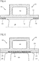
- the figure 4 shows a housing 128 and a tank 146 according to a second embodiment of the invention. This figure 4 repeats the numbering of the previous figures for identical or similar elements, the numbering being however incremented by 100.
- the second embodiment is identical to the first embodiment, it differs from it, however, in that the tank 146, and in particular its chamber 148, are inscribed in the axial length of the stator vane 126, for example between its leading edge and its trailing edge, and/or in the axial length of the platform 136.
- the chamber 148, and possibly the tank 246 as a whole, are at a distance axially from the seals 142; for example upstream and downstream of the blade 126.
- the platform 136 forms a shield which protects the chamber 148, forming a laminate with the wall 130. This configuration also improves thermal conduction.
- the figure 5 shows a housing 228 and a tank 246 according to a third embodiment of the invention. This figure 5 repeats the numbering of the previous figures for identical or similar elements, the numbering being however incremented by 200.
- the third embodiment is identical to the first embodiment, it differs however in that the reservoir 246, and in particular its chamber 248, are inscribed in the axial length of a seal 242, which surrounds for example a annular row of rotor blades 224. Seal 242 can then participate in sealing tank 246, and possibly protect it.
- the stator vanes 226 can be fixed using pins passing through the wall 230 of the casing 228, the reservoir 246 being at an axial distance from said pins. Reservoir 246 may be at a distance axially from the blades of the stator vanes 226. It may also be at a distance from the platforms 236. This arrangement promotes the fixing of the vanes 226 by their platforms 236, example when the latter are welded to the wall 230.
- the wall 230 may comprise openings closed by the platforms.
- the characteristics described for a blade can apply to all the blades of the corresponding row, as to all the rows of blades mentioned above.
Landscapes
- Engineering & Computer Science (AREA)
- Mechanical Engineering (AREA)
- General Engineering & Computer Science (AREA)
- Chemical & Material Sciences (AREA)
- Combustion & Propulsion (AREA)
- Structures Of Non-Positive Displacement Pumps (AREA)
Description
- L'invention concerne l'architecture d'une turbomachine incluant un réservoir circulaire et un compresseur. L'invention a également trait à une turbomachine axiale, notamment un turboréacteur d'avion ou un turbopropulseur d'aéronef.
- Le fonctionnement d'un turboréacteur nécessite la présence d'un réservoir d'huile propre. Ce réservoir peut être intégré dans la nacelle de la turbomachine, ou dans le corps primaire ; c'est-à-dire entre le flux primaire et le flux secondaire. Puisque la compacité reste une contrainte principale dans un turboréacteur, le réservoir d'huile doit être courbé afin de s'insérer entre deux parois annulaires délimitant les flux. La courbure s'accentue à mesure que le volume interne du réservoir augmente.
- Le document
US 8 627 667 B2 divulgue un turboréacteur double-flux avec une soufflante, un compresseur et une conduite bypass. La conduite bypass est délimitée par une paroi interne et par une paroi externe qui sont réalisées en un matériau composite avec du carbone. La conduite bypass renferme un réservoir, ce réservoir étant circulaire. Or, la capacité du réservoir reste limitée. Par ailleurs, un tel turboréacteur présente une trainée importante. - Le document
GB 1,018,538 - L'invention a pour objectif de résoudre au moins un des problèmes posés par l'art antérieur. Plus précisément, l'invention a pour objectif d'optimiser la compacité d'une turbomachine et la contenance d'un réservoir. L'invention a également pour objectif de proposer une solution simple, résistante chimiquement et mécaniquement, légère, économique, fiable, facile à produire, commode d'entretien, d'inspection aisée, et améliorant le rendement.
- L'invention a pour objet un ensemble pour turbomachine selon la revendication 1.
- Selon des modes avantageux de l'invention, l'ensemble peut comprendre une ou plusieurs des caractéristiques suivantes, prises isolément ou selon toutes les combinaisons techniques possibles :
- Le compresseur comprend au moins une rangée annulaire d'aubes en amont de la bride.
- L'ensemble comprend une rangée d'aubes statoriques s'étendant radialement depuis la surface interne.
- Les aubes sont disposées axialement au niveau de la chambre interne.
- Les aubes sont en contact thermique de la chambre interne et de la veine primaire.
- Chaque aube comprend une plateforme de fixation traversant axialement la chambre interne du réservoir.
- Le réservoir comprend une extrémité amont et une extrémité aval entre lesquelles sont disposées les aubes statoriques.
- Le réservoir comprend une cloison annulaire amont et une cloison annulaire aval, l'une desdites cloisons annulaires étant au niveau axialement d'une aube statorique.
- La distance axiale entre la bride et la cloison annulaire aval recouvre au moins quatre rangées annulaires d'aubes.
- La paroi annulaire est réalisée en matériau composite à matrice organique.
- Le carter, notamment la paroi composite, est monobloc ou formé de demi-coquilles.
- Le réservoir est formé de deux demi-tores.
- L'ensemble comprend un joint annulaire apte à coopérer par abrasion avec un rotor du compresseur, ledit joint étant disposé axialement au niveau de la chambre annulaire.
- La paroi est pleine au niveau de la chambre.
- La paroi est monobloc entre la surface interne et la surface externe et/ou au niveau axialement de la chambre, notamment sur un tronçon angulaire.
- L'ensemble comprend un compresseur avec un rotor, notamment basse-pression, le carter externe étant le carter dudit compresseur et le réservoir entourant le rotor du compresseur.
- Le rotor comporte un tambour monobloc comportant plusieurs rangées annulaires d'aubes rotoriques au niveau axialement de la chambre interne.
- La surface interne et la surface externe sont opposées selon l'épaisseur de la paroi et/ou au même niveau axialement, par exemple au niveau de la chambre.
- Le réservoir comprend une extrémité amont et une extrémité aval entre lesquelles est placé le joint.
- L'extrémité amont et l'extrémité aval sont axialement à distance des aubes.
- L'extrémité amont et l'extrémité aval sont axialement à distance du joint.
- Le joint est un joint abradable, notamment avec du silicone, ou avec une composition aluminium nickel polymère.
- L'épaisseur de la paroi est inférieure ou égale à : 10mm, ou 5mm, ou 2mm.
- Le volume de la chambre est supérieur ou égal à : 10L, ou 20L, ou 50L, ou 70L.
- La plateforme est en contact de la paroi.
- L'invention a également pour objet une turbomachine, notamment un turboréacteur d'aéronef, comprenant un ensemble, remarquable en ce que l'ensemble est conforme à l'invention, éventuellement le réservoir est un réservoir d'huile.
- Selon un mode avantageux de l'invention, la turbomachine comprend un bec de séparation annulaire avec un dispositif de dégivrage par huile, le dispositif de dégivrage étant connecté hydrauliquement au réservoir d'huile.
- Selon un mode avantageux de l'invention, la turbomachine comprend un collecteur annulaire d'huile, ledit collecteur étant connecté hydrauliquement au réservoir d'huile.
- De manière générale, les modes avantageux de chaque objet de l'invention sont également applicables aux autres objets de l'invention. Chaque objet de l'invention est combinable aux autres objets, et les objets de l'invention sont également combinables aux modes de réalisation de la description, qui en plus sont combinables entre eux, selon toutes les combinaisons techniques possibles, à moins que le contraire ne soit explicitement mentionné.
- L'invention améliore la compacité de la turbomachine car elle rapproche et fusionne le réservoir du compresseur. La chambre de ce dernier est intégrée dans la paroi annulaire. Une économie substantielle est acquise par la mutualisation de la paroi.
- En complément, un rapprochement entre le réservoir et les aubes est assuré. Par ce biais, il devient possible d'exploiter les surfaces d'échange thermique des aubes baignant dans la source froide, en l'occurrence le flux primaire. L'échange thermique s'effectue au travers de la paroi, il peut être amélioré grâce aux cloisons qui sont elles-mêmes en contact thermiques des aubes.
- La jonction du réservoir au carter permet de renforcer ce dernier. En effet, le réservoir forme un profilé rigide qui augmente le moment quadratique du réservoir.
-
- La
figure 1 représente une turbomachine axiale selon l'invention. - La
figure 2 est un schéma d'un compresseur de turbomachine selon un premier mode de réalisation de l'invention. - La
figure 3 illustre une coupe de turbomachine suivant l'axe 3-3 tracé sur lafigure 2 . - La
figure 4 représente un carter et un réservoir selon un deuxième mode de réalisation de l'invention. - La
figure 5 représente un carter et un réservoir selon un troisième mode de réalisation de l'invention. - Dans la description qui va suivre, les termes « interne » et « externe » renvoient à un positionnement par rapport à l'axe de rotation d'une turbomachine axiale. La direction axiale correspond à la direction le long de l'axe de rotation de la turbomachine. La direction radiale est perpendiculaire à l'axe de rotation. L'amont et l'aval sont en référence au sens d'écoulement principal du flux dans la turbomachine.
- La
figure 1 représente de manière simplifiée une turbomachine axiale. Il s'agit dans ce cas précis d'un turboréacteur double-flux. Le turboréacteur 2 comprend un premier niveau de compression, dit compresseur basse-pression 4, un deuxième niveau de compression, dit compresseur haute-pression 6, une chambre de combustion 8 et un ou plusieurs niveaux de turbines 10. En fonctionnement, la puissance mécanique de la turbine 10 transmise via l'arbre central jusqu'au rotor 12 met en mouvement les deux compresseurs 4 et 6. Ces derniers comportent plusieurs rangées d'aubes de rotor associées à des rangées d'aubes de stator. La rotation du rotor autour de son axe de rotation 14 permet ainsi de générer un débit d'air et de comprimer progressivement ce dernier jusqu'à l'entrée de la chambre de combustion 8. - Un ventilateur d'entrée communément désigné fan ou soufflante 16 est couplé au rotor 12 et génère un flux d'air qui se divise en un flux primaire 18 traversant les différents niveaux susmentionnés de la turbomachine, et en un flux secondaire 20 traversant un conduit annulaire (partiellement représenté) le long de la machine pour ensuite rejoindre le flux primaire en sortie de turbine.
- Des moyens de démultiplication 22, tel un ou plusieurs réducteurs épicycloïdaux, peuvent réduire la vitesse de rotation de la soufflante. Les moyens de démultiplication 22 peuvent augmenter ou réduire la vitesse de rotation du compresseur basse-pression 4 par rapport à la turbine et/ou à la soufflante 12. Le flux secondaire 20 peut être accéléré de sorte à générer une réaction de poussée nécessaire au vol d'un avion. Les flux primaire 18 et secondaire 20 sont des flux annulaires coaxiaux et emmanchés l'un dans l'autre.
- La turbomachine 2 peut comprendre un circuit hydraulique, notamment relié à un réservoir. Le circuit peut être branché à un échangeur de chaleur permettant de refroidir l'huile issue de paliers de la turbomachine et des moyens de démultiplication 22.
- La
figure 2 est une vue en coupe d'un compresseur d'une turbomachine axiale telle que celle de lafigure 1 . Le compresseur peut être un compresseur basse-pression 4. Le rotor 12 comprend plusieurs rangées d'aubes rotoriques 24, en l'occurrence trois. Il peut être un tambour monobloc aubagé, ou comprendre des aubes à fixation par queue d'aronde dans une gorge périmétrique. L'axe de rotation 14 est tracé. - Le compresseur basse-pression 4 comprend plusieurs redresseurs, en l'occurrence quatre, qui contiennent chacun une rangée d'aubes statoriques 26. Les redresseurs sont associés au fan 16 ou à une rangée d'aubes rotoriques pour redresser le flux d'air, de sorte à convertir la vitesse du flux en pression, notamment en pression statique. Les aubes (24 ; 26) présentent des surfaces concaves et convexes, configurées pour comprimer le flux.
- Les aubes statoriques 26 s'étendent essentiellement radialement depuis un carter externe 28. Elles peuvent être vissées, collées ou soudées à la paroi annulaire 30. Grâce à des brides annulaires 32, le carter 28 peut être relié au support de soufflante de la turbomachine, ou au bec de séparation 34 partageant le flux primaire 18 et le flux secondaire 20 en aval de la soufflante 16. La paroi 30 peut être réalisée en matériau composite à matrice organique et à fibres de carbone, ou en métal tel du titane. Son épaisseur, mesurée radialement, peut être comprise entre 3mm et 5mm inclus.
- Les aubes statoriques 26 peuvent être munies de plateformes de fixation 36. Celles-ci sont plaquées contre la surface circulaire interne 38 de la paroi 30. La bride 32 s'étend radialement depuis la surface circulaire externe 40 qui est opposée à la surface interne 38 selon l'épaisseur de la paroi 30.
- La paroi 30 peut recevoir un ou plusieurs joints annulaires 42, par exemple au contact de la surface interne 38 et/ou des plateformes 36. Les joints 42 peuvent être du type abradable, en ce sens qu'ils sont aptes à s'effriter au contact du rotor 12. Ils peuvent assurer des étanchéités avec les rangées d'aubes rotoriques 24. Des viroles internes 44 suspendues aux aubes statoriques 26 peuvent assurer des étanchéités avec des léchettes du rotor 12.
- Un réservoir 46, notamment d'huile, est associé au compresseur 4. Ils partagent la paroi 30. Celle-là peut délimiter la chambre interne 48 du réservoir 46. Cette dernière peut être circulaire et entourer l'axe de rotation du rotor 12. Ainsi, la chambre 48 est entre le flux primaire 18 et le flux secondaire 20. Le carter peut être formé de plusieurs viroles externes, chacune étant une boucle fermée, le réservoir étant formé sur une des viroles. Alternativement, le réservoir peut être formé de demi-coquilles.
- Le réservoir s'étend axialement d'une certaine valeur, préférentiellement apte à recouvrir au moins une rangée d'aube, voir au moins deux ou au moins trois rangées d'aubes.
- La bride 32 est à une distance du réservoir 46 qui est d'au moins la dimension axiale du réservoir 46. Ceci permet une versatilité du système, limitant l'encombrement du réservoir et facilitant le montage du carter d'une part et potentiellement d'autres éléments autour du carter.
- La chambre 48 peut être à cheval sur une ou plusieurs rangées d'aubes statoriques 26, et peut éventuellement traverser axialement un joint 42 et/ou des aubes rotoriques 24. Elle peut être axialement au niveau d'une ou de plusieurs rangées de plateformes 36. Les aubes statoriques 26 peuvent comprendre des pales s'étendant radialement depuis les plateformes 36 dans la veine primaire, qui est notamment traversée par le flux primaire 18. La chambre 48 peut être axialement au niveau d'au moins une ou plusieurs rangées de pales.
- Le réservoir 46 peut être cloisonné à l'aide de plusieurs parties annulaires. Il peut inclure une cloison annulaire amont 50 et une cloison annulaire aval 52. Il peut inclure une cloison annulaire externe 54 entourant la surface externe 40, et/ou reliant les cloisons amont 50 et aval 52. La paroi 30 et les cloisons 50, 52 et 54 renferment la chambre 48, notamment de manière étanche.
- La cloison amont 50 et aval 52 peuvent être au niveau de deux rangées d'aubes statoriques 26. La chambre peut être en contact thermique des aubes statoriques 26 via la paroi 30. Par exemple, la cloison amont 50 peut être en contact thermique d'une rangée d'aubes 26, et/ou la cloison aval 52 peut être en contact thermique d'une rangée d'aubes 26, éventuellement d'une autre rangée. Ainsi, les cloisons 50 et 52 peuvent également être refroidies grâce au flux primaire 18, puis refroidir à leur tour l'huile.
- Les cloisons (50-54) et la paroi 30 peuvent former un ensemble monobloc et éventuellement venu de matière.
- Eventuellement, les cloisons (50-54) et la paroi 30 peuvent être formées de tronçons angulaires monoblocs et venus de matière. Chaque tronçon peut comprendre une pluralité d'aubes 26, par exemple de dix à vingt. Les tronçons peuvent être produits par fabrication additive, puis être reliés les uns aux autres bout-à-bout angulariement, par exemple pour soudage ou par collage. Des joints peuvent être ajoutés aux interfaces angulaires des tronçons, par exemple dans l'épaisseur des cloisons et de la paroi. Ainsi, le carter 28 et le réservoir 46 se renforcent mutuellement.
- La chambre 48 peut être connectée à un dispositif de dégivrage du bec de séparation 34 et/ou des aubes statoriques 26. Des conduites (non représentés) peuvent être branchées à la chambre pour canaliser un débit d'huile depuis et vers la chambre 48. Cette configuration simplifie l'adduction de fluide caloporteur, et optimise le dégivrage.
- La
figure 3 est une coupe de la turbomachine suivant l'axe 3-3 tracé sur lafigure 2 . La rangée annulaire d'aubes statoriques 26 et la virole interne 44 sont représentées autour de l'axe de rotation 14 du compresseur 4. Le nombre d'aubes 26 est ici purement figuratif, et peut être supérieur ou égal à 50 ou à 100. - De l'huile 56 remplit partiellement la chambre 48. Le réservoir convient pour d'autres fluides ou liquides, éventuellement grâce à des adaptations. La forme annulaire du réservoir 46 en augmente la hauteur, ce qui y améliore le dégazage et la décantation des particules solides issues de l'usure. L'augmentation de la surface d'enveloppe en contact de la chambre 48 favorise l'échange thermique.
- En fonctionnement, l'huile 56 peut atteindre les 200°C. Elle peut également inclure des additifs rendant l'huile d'avantage corrosive. La présence de ces additifs peut découler du domaine des turbomachines et/ou des turboréacteurs. La cloison 30 peut former une séparation étanche et/ou une jonction structurelle entre les aubes 26 et la chambre 48. La cloison externe 54 peut l'entourer.
- La
figure 4 représente un carter 128 et un réservoir 146 selon un deuxième mode de réalisation de l'invention. Cettefigure 4 reprend la numérotation des figures précédentes pour les éléments identiques ou similaires, la numération étant toutefois incrémentée de 100. - Le deuxième de mode de réalisation est identique au premier mode de réalisation, il s'en distingue toutefois en ce que le réservoir 146, et notamment sa chambre 148, sont inscrits dans la longueur axiale de l'aube statorique 126, par exemple entre son bord d'attaque et son bord de fuite, et/ou dans la longueur axiale de la plateforme 136. La chambre 148, et éventuellement le réservoir 246 dans son ensemble, sont à distance axialement des joints 142 ; par exemple en amont et en aval de l'aube 126.
- Via cette disposition, la plateforme 136 forme un blindage qui protège la chambre 148, en formant un laminé avec la paroi 130. Cette configuration améliore également la conduction thermique.
- La
figure 5 représente un carter 228 et un réservoir 246 selon un troisième mode de réalisation de l'invention. Cettefigure 5 reprend la numérotation des figures précédentes pour les éléments identiques ou similaires, la numération étant toutefois incrémentée de 200. - Le troisième de mode de réalisation est identique au premier mode de réalisation, il s'en distingue toutefois en ce que le réservoir 246, et notamment sa chambre 248, sont inscrits dans la longueur axiale d'un joint 242, qui entoure par exemple une rangée annulaire d'aubes rotoriques 224. Le joint 242 peut alors participer à l'étanchéité du réservoir 246, et éventuellement le protéger. Les aubes statoriques 226 peuvent être fixées à l'aide d'axes traversant la paroi 230 du carter 228, le réservoir 246 étant à distance axialement desdits axes. Le réservoir 246 peut être à distance axialement des pales des aubes statoriques 226. Il peut également être à distance des plateformes 236. Cet agencement favorise la fixation des aubes 226 par leurs plateformes 236, par exemple lorsque ces dernières sont soudées à la paroi 230. La paroi 230 peut comprendre des ouvertures fermées par les plateformes.
- Cela éloigne les fixations du réservoir, ce qui préserve la chambre tout en simplifiant ces mêmes fixations, qu'il s'agisse de collage, de soudures ou de vis, ou de tout autre moyen équivalent.
- Si ces plateformes avaient été au niveau axialement de la chambre, elles la délimiteraient en combinaison avec la paroi.
- Selon l'invention, il est possible de pourvoir un carter de compresseur de plusieurs réservoirs répartis axialement, chaque réservoir étant selon un des différents modes de réalisation de l'invention.
- Dans toute description, les caractéristiques décrites pour une aube peuvent s'appliquer à toutes les aubes de la rangée correspondante, comme à toutes les rangées d'aubes évoquées précédemment.
Claims (15)
- Ensemble pour turbomachine (2), l'ensemble comprenant: un axe de rotation (14) de la turbomachine (2), un carter externe (28 ; 128 ; 228) de compresseur (4 ; 6) avec une paroi annulaire (30 ; 130 ; 230) présentant une surface circulaire interne (38) délimitant une veine primaire du compresseur (4 ; 6), et un réservoir (46 ; 146 ; 246) pour liquide avec une chambre interne circulaire (48 ; 148 ; 248) autour de l'axe de rotation (14), la paroi (30 ; 130 ; 230) comprenant, une surface circulaire externe (40) qui délimite la chambre interne (48 ; 148 ; 248) du réservoir (46 ; 146 ; 246), caractérisé en ce que le carter (28; 128; 228) comprend une bride annulaire de fixation (32) en amont, et axialement à distance, du réservoir (46 ; 146 ; 246), la bride (32) s'étendant radialement depuis la paroi annulaire (30 ; 130 ; 230), et la bride (32) et le réservoir (46; 146; 246) étant séparés axialement d'une distance au moins égale à la dimension axiale du réservoir (46 ; 146 ; 246).
- Ensemble selon la revendication 1, caractérisé en ce qu'il comprend au moins une rangée annulaire d'aubes (24 ; 26) en amont de la bride (32).
- Ensemble selon la revendication 1 ou 2, caractérisé en ce qu'il comprend une rangée d'aubes statoriques (26; 126; 226) s'étendant radialement depuis la surface interne (38) et disposées axialement au niveau de la chambre interne (48 ; 148), les aubes (26 ; 126) étant préférentiellement en contact thermique de la chambre interne (48 ; 148) et de la veine primaire.
- Ensemble selon la revendication 3, caractérisé en ce que chaque aube (126) comprend une plateforme de fixation (136) s'étendant sur toute la longueur axiale la chambre interne (148) du réservoir (146).
- Ensemble selon l'une des revendications 3 ou 4, caractérisé en ce que le réservoir comprend une extrémité amont et une extrémité aval entre lesquelles sont disposées les aubes statoriques.
- Ensemble selon l'une des revendications 3 à 5, caractérisé en ce que le réservoir (46 ; 146) comprend une cloison annulaire amont (50) et une cloison annulaire aval (52), l'une desdites cloisons annulaires (50 ; 52) étant au niveau axialement d'une aube statorique (26 ; 126).
- Ensemble selon la revendication 6, caractérisé en ce que la distance axiale entre la bride (32) et la cloison annulaire aval (52) recouvre au moins quatre rangées annulaires d'aubes (24 ; 26).
- Ensemble selon l'une des revendications 1 à 7, caractérisé en ce que le réservoir (46 ; 146 ; 246) est formé de deux demi-tores.
- Ensemble selon l'une des revendications 1 à 8, caractérisé en ce qu'il comprend un joint annulaire (42 ; 242) apte à coopérer par abrasion avec un rotor (12) du compresseur (4 ; 6), ledit joint étant disposé axialement au niveau de la chambre annulaire (26 ; 226).
- Ensemble selon l'une des revendications 1 à 9, caractérisé en ce que la paroi (30 ; 130 ; 230) est pleine au niveau de la chambre (48 ; 148 ; 248).
- Ensemble selon l'une des revendications 1 à 10, caractérisé en ce qu'il comprend un compresseur (4 ; 6) avec un rotor (12), notamment un compresseur basse-pression, le carter externe (28; 128; 228) étant le carter dudit compresseur et le réservoir (46 ; 146 ; 246) entourant le rotor (12) du compresseur (4 ; 6).
- Ensemble selon la revendication 11, caractérisé en ce que le rotor (12) comporte un tambour monobloc comportant plusieurs rangées annulaires d'aubes rotoriques (24) au niveau axialement de la chambre interne (48 ; 248).
- Turbomachine (2), notamment un turboréacteur d'aéronef, comprenant un ensemble, caractérisée en ce que l'ensemble est conforme à l'une des revendications 1 à 12, éventuellement le réservoir (46 ; 146 ; 246) est un réservoir d'huile.
- Turbomachine (2) selon la revendication 13, caractérisée en ce qu'elle comprend un bec de séparation annulaire (34) avec un dispositif de dégivrage par huile, le dispositif de dégivrage étant connecté hydrauliquement au réservoir d'huile (46 ; 146 ; 246).
- Turbomachine (2) selon l'une des revendications 13 à 14, caractérisée en ce qu'elle comprend un collecteur annulaire d'huile, ledit collecteur étant connecté hydrauliquement au réservoir d'huile (46 ; 146 ; 246).
Applications Claiming Priority (2)
| Application Number | Priority Date | Filing Date | Title |
|---|---|---|---|
| BE2017/5735A BE1025642B1 (fr) | 2017-10-16 | 2017-10-16 | Carter de compresseur avec reservoir d'huile pour turbomachine |
| PCT/EP2018/073559 WO2019076519A1 (fr) | 2017-10-16 | 2018-09-03 | Carter extérieur de turbo-compresseur avec réservoir d'huile intégré |
Publications (2)
| Publication Number | Publication Date |
|---|---|
| EP3698050A1 EP3698050A1 (fr) | 2020-08-26 |
| EP3698050B1 true EP3698050B1 (fr) | 2022-06-08 |
Family
ID=60320590
Family Applications (1)
| Application Number | Title | Priority Date | Filing Date |
|---|---|---|---|
| EP18765092.4A Active EP3698050B1 (fr) | 2017-10-16 | 2018-09-03 | Carter extérieur de turbo-compresseur avec réservoir d'huile intégré |
Country Status (4)
| Country | Link |
|---|---|
| US (1) | US11506068B2 (fr) |
| EP (1) | EP3698050B1 (fr) |
| BE (1) | BE1025642B1 (fr) |
| WO (1) | WO2019076519A1 (fr) |
Families Citing this family (5)
| Publication number | Priority date | Publication date | Assignee | Title |
|---|---|---|---|---|
| BE1026218B1 (fr) * | 2018-04-19 | 2019-11-21 | Safran Aero Boosters S.A. | Dispositif de mesure de niveau pour réservoir d'huile de turbomachine |
| JP7445452B2 (ja) * | 2020-02-14 | 2024-03-07 | 川崎重工業株式会社 | ガスタービンエンジン |
| US11788549B2 (en) * | 2021-10-04 | 2023-10-17 | General Electric Company | Turbofan blade blocking apparatus |
| FR3142503A1 (fr) * | 2022-11-30 | 2024-05-31 | Safran Aircraft Engines | Ensemble de tubomachine muni d’une virole monobloc |
| CN119145956B (zh) * | 2024-11-18 | 2025-02-14 | 中国航发湖南动力机械研究所 | 涡轴发动机集成机匣 |
Family Cites Families (12)
| Publication number | Priority date | Publication date | Assignee | Title |
|---|---|---|---|---|
| GB1018538A (en) * | 1964-07-06 | 1966-01-26 | Rolls Royce | Gas turbine engine |
| GB1322405A (en) * | 1970-10-02 | 1973-07-04 | Secr Defence | Oil systems for gas turbine engines |
| US4592204A (en) * | 1978-10-26 | 1986-06-03 | Rice Ivan G | Compression intercooled high cycle pressure ratio gas generator for combined cycles |
| IT1219194B (it) * | 1988-04-11 | 1990-05-03 | Aris Spa | Turboreattore leggero modulare |
| US8627667B2 (en) | 2008-12-29 | 2014-01-14 | Roll-Royce Corporation | Gas turbine engine duct having a coupled fluid volume |
| EP2883688B1 (fr) * | 2013-12-13 | 2021-09-22 | Safran Aero Boosters SA | Carter annulaire composite de compresseur de turbomachine et procédé d'obtention de celui-ci |
| FR3046201B1 (fr) * | 2015-12-24 | 2018-01-19 | Safran Aircraft Engines | Turboreacteur avec un moyen de reprise de poussee sur le carter inter-compresseurs |
| US10695704B2 (en) * | 2016-07-20 | 2020-06-30 | General Electric Company | Multi-station debris separation system |
| US10787920B2 (en) * | 2016-10-12 | 2020-09-29 | General Electric Company | Turbine engine inducer assembly |
| US10851712B2 (en) * | 2017-06-27 | 2020-12-01 | General Electric Company | Clearance control device |
| FR3087226B1 (fr) * | 2018-10-10 | 2020-10-23 | Safran Aircraft Engines | Turbomachine d'aeronef a reducteur mecanique et a turbine contrarotative |
| FR3087857B1 (fr) * | 2018-10-30 | 2021-02-12 | Safran Aircraft Engines | Module de soufflante a pales a calage variable |
-
2017
- 2017-10-16 BE BE2017/5735A patent/BE1025642B1/fr active IP Right Grant
-
2018
- 2018-09-03 EP EP18765092.4A patent/EP3698050B1/fr active Active
- 2018-09-03 WO PCT/EP2018/073559 patent/WO2019076519A1/fr not_active Ceased
- 2018-09-03 US US16/627,632 patent/US11506068B2/en active Active
Also Published As
| Publication number | Publication date |
|---|---|
| WO2019076519A1 (fr) | 2019-04-25 |
| BE1025642B1 (fr) | 2019-05-15 |
| US11506068B2 (en) | 2022-11-22 |
| US20210164357A1 (en) | 2021-06-03 |
| BE1025642A1 (fr) | 2019-05-10 |
| EP3698050A1 (fr) | 2020-08-26 |
Similar Documents
| Publication | Publication Date | Title |
|---|---|---|
| EP3698050B1 (fr) | Carter extérieur de turbo-compresseur avec réservoir d'huile intégré | |
| BE1023531B1 (fr) | Dispositif degivrant de bec de separation de compresseur de turbomachine axiale | |
| EP3377732B1 (fr) | Partie avant de turbomachine d'aéronef | |
| EP2821597B1 (fr) | Bec de séparation avec tôle formant une surface de guidage du flux et un canal de dégivrage | |
| BE1024941B1 (fr) | Controle actif de jeu pour compresseur de turbomachine | |
| WO2019122657A1 (fr) | Aube fixe de redresseur d'une soufflante de turbomachine | |
| BE1024935A1 (fr) | Compresseur avec virole interne segmentee pour turbomachine axiale | |
| EP2803822B1 (fr) | Système de prélèvement d'air de turbomachine axiale | |
| FR3016956A1 (fr) | Echangeur de chaleur d'une turbomachine | |
| EP4168658B1 (fr) | Turbomachine d'aeronef a cycle recupere | |
| FR3054263A1 (fr) | Carter intermediaire de turbomachine d'aeronef realise d'une seule piece de fonderie avec une canalisation de lubrifiant | |
| FR3064682A1 (fr) | Carter intermediaire de turbomachine d'aeronef comprenant un embout de passage de lubrifiant connecte a une aube de carter par une piece de raccord | |
| BE1023619A1 (fr) | Carter de compresseur de turbomachine axiale | |
| BE1025283B1 (fr) | Systeme d'etancheite pour compresseur de turbomachine | |
| BE1024524B1 (fr) | Virole interne et aube orientable de compresseur de turbomachine axiale | |
| FR3119199A1 (fr) | Conduit de decharge a etancheite perfectionnee | |
| FR2999249A1 (fr) | Compresseur pour turbomachine dote de moyens de refroidissement d'un joint tournant assurant l'etancheite entre un redresseur et un rotor | |
| EP4055259A1 (fr) | Echangeur de chaleur comportant une paroi perturbatrice à générateurs de turbulence creux | |
| EP3673154B1 (fr) | Conduit de décharge d'un moyeu de carter intermédiaire pour turboréacteur d'aéronef comportant des canaux de refroidissement | |
| BE1024605B1 (fr) | Carter avec bras aspirant pour turbomachine axiale | |
| FR3065483A1 (fr) | Dispositif d'etancheite entre rotor et stator de turbomachine | |
| EP4314491B1 (fr) | Dispositif d'etancheite et de reinjection d'un flux de contournement pour distributeur de turbine | |
| FR3009583A1 (fr) | Turbomachine a organe de deviation d’objets etrangers | |
| EP3382155B1 (fr) | Système d'étanchéité pour turbomachine et turbomachine associée | |
| FR3064295B1 (fr) | Carter intermediaire de turbomachine d'aeronef comprenant un embout de passage de lubrifiant solidaire d'une plateforme |
Legal Events
| Date | Code | Title | Description |
|---|---|---|---|
| STAA | Information on the status of an ep patent application or granted ep patent |
Free format text: STATUS: UNKNOWN |
|
| STAA | Information on the status of an ep patent application or granted ep patent |
Free format text: STATUS: THE INTERNATIONAL PUBLICATION HAS BEEN MADE |
|
| PUAI | Public reference made under article 153(3) epc to a published international application that has entered the european phase |
Free format text: ORIGINAL CODE: 0009012 |
|
| STAA | Information on the status of an ep patent application or granted ep patent |
Free format text: STATUS: REQUEST FOR EXAMINATION WAS MADE |
|
| 17P | Request for examination filed |
Effective date: 20191119 |
|
| AK | Designated contracting states |
Kind code of ref document: A1 Designated state(s): AL AT BE BG CH CY CZ DE DK EE ES FI FR GB GR HR HU IE IS IT LI LT LU LV MC MK MT NL NO PL PT RO RS SE SI SK SM TR |
|
| AX | Request for extension of the european patent |
Extension state: BA ME |
|
| DAV | Request for validation of the european patent (deleted) | ||
| DAX | Request for extension of the european patent (deleted) | ||
| GRAP | Despatch of communication of intention to grant a patent |
Free format text: ORIGINAL CODE: EPIDOSNIGR1 |
|
| STAA | Information on the status of an ep patent application or granted ep patent |
Free format text: STATUS: GRANT OF PATENT IS INTENDED |
|
| INTG | Intention to grant announced |
Effective date: 20211221 |
|
| GRAS | Grant fee paid |
Free format text: ORIGINAL CODE: EPIDOSNIGR3 |
|
| GRAA | (expected) grant |
Free format text: ORIGINAL CODE: 0009210 |
|
| STAA | Information on the status of an ep patent application or granted ep patent |
Free format text: STATUS: THE PATENT HAS BEEN GRANTED |
|
| AK | Designated contracting states |
Kind code of ref document: B1 Designated state(s): AL AT BE BG CH CY CZ DE DK EE ES FI FR GB GR HR HU IE IS IT LI LT LU LV MC MK MT NL NO PL PT RO RS SE SI SK SM TR |
|
| REG | Reference to a national code |
Ref country code: AT Ref legal event code: REF Ref document number: 1497109 Country of ref document: AT Kind code of ref document: T Effective date: 20220615 Ref country code: CH Ref legal event code: EP |
|
| REG | Reference to a national code |
Ref country code: DE Ref legal event code: R096 Ref document number: 602018036538 Country of ref document: DE |
|
| REG | Reference to a national code |
Ref country code: IE Ref legal event code: FG4D Free format text: LANGUAGE OF EP DOCUMENT: FRENCH |
|
| REG | Reference to a national code |
Ref country code: LT Ref legal event code: MG9D |
|
| REG | Reference to a national code |
Ref country code: NL Ref legal event code: MP Effective date: 20220608 |
|
| PG25 | Lapsed in a contracting state [announced via postgrant information from national office to epo] |
Ref country code: SE Free format text: LAPSE BECAUSE OF FAILURE TO SUBMIT A TRANSLATION OF THE DESCRIPTION OR TO PAY THE FEE WITHIN THE PRESCRIBED TIME-LIMIT Effective date: 20220608 Ref country code: NO Free format text: LAPSE BECAUSE OF FAILURE TO SUBMIT A TRANSLATION OF THE DESCRIPTION OR TO PAY THE FEE WITHIN THE PRESCRIBED TIME-LIMIT Effective date: 20220908 Ref country code: LT Free format text: LAPSE BECAUSE OF FAILURE TO SUBMIT A TRANSLATION OF THE DESCRIPTION OR TO PAY THE FEE WITHIN THE PRESCRIBED TIME-LIMIT Effective date: 20220608 Ref country code: HR Free format text: LAPSE BECAUSE OF FAILURE TO SUBMIT A TRANSLATION OF THE DESCRIPTION OR TO PAY THE FEE WITHIN THE PRESCRIBED TIME-LIMIT Effective date: 20220608 Ref country code: GR Free format text: LAPSE BECAUSE OF FAILURE TO SUBMIT A TRANSLATION OF THE DESCRIPTION OR TO PAY THE FEE WITHIN THE PRESCRIBED TIME-LIMIT Effective date: 20220909 Ref country code: FI Free format text: LAPSE BECAUSE OF FAILURE TO SUBMIT A TRANSLATION OF THE DESCRIPTION OR TO PAY THE FEE WITHIN THE PRESCRIBED TIME-LIMIT Effective date: 20220608 Ref country code: ES Free format text: LAPSE BECAUSE OF FAILURE TO SUBMIT A TRANSLATION OF THE DESCRIPTION OR TO PAY THE FEE WITHIN THE PRESCRIBED TIME-LIMIT Effective date: 20220608 Ref country code: BG Free format text: LAPSE BECAUSE OF FAILURE TO SUBMIT A TRANSLATION OF THE DESCRIPTION OR TO PAY THE FEE WITHIN THE PRESCRIBED TIME-LIMIT Effective date: 20220908 |
|
| REG | Reference to a national code |
Ref country code: AT Ref legal event code: MK05 Ref document number: 1497109 Country of ref document: AT Kind code of ref document: T Effective date: 20220608 |
|
| PG25 | Lapsed in a contracting state [announced via postgrant information from national office to epo] |
Ref country code: RS Free format text: LAPSE BECAUSE OF FAILURE TO SUBMIT A TRANSLATION OF THE DESCRIPTION OR TO PAY THE FEE WITHIN THE PRESCRIBED TIME-LIMIT Effective date: 20220608 Ref country code: LV Free format text: LAPSE BECAUSE OF FAILURE TO SUBMIT A TRANSLATION OF THE DESCRIPTION OR TO PAY THE FEE WITHIN THE PRESCRIBED TIME-LIMIT Effective date: 20220608 |
|
| PG25 | Lapsed in a contracting state [announced via postgrant information from national office to epo] |
Ref country code: NL Free format text: LAPSE BECAUSE OF FAILURE TO SUBMIT A TRANSLATION OF THE DESCRIPTION OR TO PAY THE FEE WITHIN THE PRESCRIBED TIME-LIMIT Effective date: 20220608 |
|
| PG25 | Lapsed in a contracting state [announced via postgrant information from national office to epo] |
Ref country code: SM Free format text: LAPSE BECAUSE OF FAILURE TO SUBMIT A TRANSLATION OF THE DESCRIPTION OR TO PAY THE FEE WITHIN THE PRESCRIBED TIME-LIMIT Effective date: 20220608 Ref country code: SK Free format text: LAPSE BECAUSE OF FAILURE TO SUBMIT A TRANSLATION OF THE DESCRIPTION OR TO PAY THE FEE WITHIN THE PRESCRIBED TIME-LIMIT Effective date: 20220608 Ref country code: RO Free format text: LAPSE BECAUSE OF FAILURE TO SUBMIT A TRANSLATION OF THE DESCRIPTION OR TO PAY THE FEE WITHIN THE PRESCRIBED TIME-LIMIT Effective date: 20220608 Ref country code: PT Free format text: LAPSE BECAUSE OF FAILURE TO SUBMIT A TRANSLATION OF THE DESCRIPTION OR TO PAY THE FEE WITHIN THE PRESCRIBED TIME-LIMIT Effective date: 20221010 Ref country code: EE Free format text: LAPSE BECAUSE OF FAILURE TO SUBMIT A TRANSLATION OF THE DESCRIPTION OR TO PAY THE FEE WITHIN THE PRESCRIBED TIME-LIMIT Effective date: 20220608 Ref country code: CZ Free format text: LAPSE BECAUSE OF FAILURE TO SUBMIT A TRANSLATION OF THE DESCRIPTION OR TO PAY THE FEE WITHIN THE PRESCRIBED TIME-LIMIT Effective date: 20220608 Ref country code: AT Free format text: LAPSE BECAUSE OF FAILURE TO SUBMIT A TRANSLATION OF THE DESCRIPTION OR TO PAY THE FEE WITHIN THE PRESCRIBED TIME-LIMIT Effective date: 20220608 |
|
| PG25 | Lapsed in a contracting state [announced via postgrant information from national office to epo] |
Ref country code: PL Free format text: LAPSE BECAUSE OF FAILURE TO SUBMIT A TRANSLATION OF THE DESCRIPTION OR TO PAY THE FEE WITHIN THE PRESCRIBED TIME-LIMIT Effective date: 20220608 Ref country code: IS Free format text: LAPSE BECAUSE OF FAILURE TO SUBMIT A TRANSLATION OF THE DESCRIPTION OR TO PAY THE FEE WITHIN THE PRESCRIBED TIME-LIMIT Effective date: 20221008 |
|
| REG | Reference to a national code |
Ref country code: DE Ref legal event code: R097 Ref document number: 602018036538 Country of ref document: DE |
|
| PG25 | Lapsed in a contracting state [announced via postgrant information from national office to epo] |
Ref country code: AL Free format text: LAPSE BECAUSE OF FAILURE TO SUBMIT A TRANSLATION OF THE DESCRIPTION OR TO PAY THE FEE WITHIN THE PRESCRIBED TIME-LIMIT Effective date: 20220608 |
|
| PLBE | No opposition filed within time limit |
Free format text: ORIGINAL CODE: 0009261 |
|
| STAA | Information on the status of an ep patent application or granted ep patent |
Free format text: STATUS: NO OPPOSITION FILED WITHIN TIME LIMIT |
|
| PG25 | Lapsed in a contracting state [announced via postgrant information from national office to epo] |
Ref country code: MC Free format text: LAPSE BECAUSE OF FAILURE TO SUBMIT A TRANSLATION OF THE DESCRIPTION OR TO PAY THE FEE WITHIN THE PRESCRIBED TIME-LIMIT Effective date: 20220608 Ref country code: DK Free format text: LAPSE BECAUSE OF FAILURE TO SUBMIT A TRANSLATION OF THE DESCRIPTION OR TO PAY THE FEE WITHIN THE PRESCRIBED TIME-LIMIT Effective date: 20220608 |
|
| REG | Reference to a national code |
Ref country code: CH Ref legal event code: PL |
|
| 26N | No opposition filed |
Effective date: 20230310 |
|
| PG25 | Lapsed in a contracting state [announced via postgrant information from national office to epo] |
Ref country code: SI Free format text: LAPSE BECAUSE OF FAILURE TO SUBMIT A TRANSLATION OF THE DESCRIPTION OR TO PAY THE FEE WITHIN THE PRESCRIBED TIME-LIMIT Effective date: 20220608 |
|
| PG25 | Lapsed in a contracting state [announced via postgrant information from national office to epo] |
Ref country code: LU Free format text: LAPSE BECAUSE OF NON-PAYMENT OF DUE FEES Effective date: 20220903 |
|
| PG25 | Lapsed in a contracting state [announced via postgrant information from national office to epo] |
Ref country code: LI Free format text: LAPSE BECAUSE OF NON-PAYMENT OF DUE FEES Effective date: 20220930 Ref country code: IE Free format text: LAPSE BECAUSE OF NON-PAYMENT OF DUE FEES Effective date: 20220903 Ref country code: CH Free format text: LAPSE BECAUSE OF NON-PAYMENT OF DUE FEES Effective date: 20220930 |
|
| PG25 | Lapsed in a contracting state [announced via postgrant information from national office to epo] |
Ref country code: IT Free format text: LAPSE BECAUSE OF FAILURE TO SUBMIT A TRANSLATION OF THE DESCRIPTION OR TO PAY THE FEE WITHIN THE PRESCRIBED TIME-LIMIT Effective date: 20220608 |
|
| PG25 | Lapsed in a contracting state [announced via postgrant information from national office to epo] |
Ref country code: CY Free format text: LAPSE BECAUSE OF FAILURE TO SUBMIT A TRANSLATION OF THE DESCRIPTION OR TO PAY THE FEE WITHIN THE PRESCRIBED TIME-LIMIT Effective date: 20220608 |
|
| PG25 | Lapsed in a contracting state [announced via postgrant information from national office to epo] |
Ref country code: MK Free format text: LAPSE BECAUSE OF FAILURE TO SUBMIT A TRANSLATION OF THE DESCRIPTION OR TO PAY THE FEE WITHIN THE PRESCRIBED TIME-LIMIT Effective date: 20220608 Ref country code: HU Free format text: LAPSE BECAUSE OF FAILURE TO SUBMIT A TRANSLATION OF THE DESCRIPTION OR TO PAY THE FEE WITHIN THE PRESCRIBED TIME-LIMIT; INVALID AB INITIO Effective date: 20180903 |
|
| PG25 | Lapsed in a contracting state [announced via postgrant information from national office to epo] |
Ref country code: TR Free format text: LAPSE BECAUSE OF FAILURE TO SUBMIT A TRANSLATION OF THE DESCRIPTION OR TO PAY THE FEE WITHIN THE PRESCRIBED TIME-LIMIT Effective date: 20220608 |
|
| PG25 | Lapsed in a contracting state [announced via postgrant information from national office to epo] |
Ref country code: MT Free format text: LAPSE BECAUSE OF FAILURE TO SUBMIT A TRANSLATION OF THE DESCRIPTION OR TO PAY THE FEE WITHIN THE PRESCRIBED TIME-LIMIT Effective date: 20220608 |
|
| PG25 | Lapsed in a contracting state [announced via postgrant information from national office to epo] |
Ref country code: BG Free format text: LAPSE BECAUSE OF FAILURE TO SUBMIT A TRANSLATION OF THE DESCRIPTION OR TO PAY THE FEE WITHIN THE PRESCRIBED TIME-LIMIT Effective date: 20220608 |
|
| PG25 | Lapsed in a contracting state [announced via postgrant information from national office to epo] |
Ref country code: BG Free format text: LAPSE BECAUSE OF FAILURE TO SUBMIT A TRANSLATION OF THE DESCRIPTION OR TO PAY THE FEE WITHIN THE PRESCRIBED TIME-LIMIT Effective date: 20220608 |
|
| PGFP | Annual fee paid to national office [announced via postgrant information from national office to epo] |
Ref country code: DE Payment date: 20250919 Year of fee payment: 8 |
|
| PGFP | Annual fee paid to national office [announced via postgrant information from national office to epo] |
Ref country code: BE Payment date: 20250919 Year of fee payment: 8 Ref country code: GB Payment date: 20250923 Year of fee payment: 8 |
|
| PGFP | Annual fee paid to national office [announced via postgrant information from national office to epo] |
Ref country code: FR Payment date: 20250924 Year of fee payment: 8 |